


Brocade Communications Systems FCX Series, FCX 624S, FCX 648S, FCX 624S-F, FCX 624S-HPOE Hardware Installation Manual
...Page 1

53-1002977-01
30 September 2013
Brocade FCX Series
Hardware Installation Guide
Supporting FastIron Software Release 08.0.01
Page 2

Copyright © 2013, Brocade Communication Systems, Inc. All Rights Reserved.
ADX, AnyIO, Brocade, Brocade Assurance, the B-wing symbol, DCX, Fabric OS, FastIron , ICX, MLX, MyBrocade, NetIron, OpenScript,
ServerIron, VCS, VDX, and Vyatta are registered trademarks, and HyperEdge, The Effortless Network, and The On-Demand Data Center
are trademarks of Brocade Communications Systems, Inc., in the United States and/or in other countries. Other brands, products, or service
names mentioned may be trademarks of their respective owners.
Notice: This document is for informational purposes only and does not set forth any warranty, expressed or implied, concerning any
equipment, equipment feature, or service offered or to be offered by Brocade. Brocade reserves the right to make changes to this document
at any time, without notice, and assumes no responsibility for its use. This informational document describes features that may not be
currently available. Contact a Brocade sales office for information on feature and product availability. Export of technical data contained in
this document may require an export license from the United States government.
The authors and Brocade Communication Systems, Inc. shall have no liability or responsibility to any person or entity with respect to any
loss, cost, liability, or damages arising from the information contained in this book or the computer programs that accompany it.
The product described by this document may contain “open source” software covered by the GNU General Public License or other open
source license agreements. To find out which open source software is included in Brocade products, view the licensing terms applicable to
the open source software, and obtain a copy of the programming source code, please visit http://www.brocade.com/support/oscd.
Page 3

Contents
Preface.....................................................................................................................................5
Document conventions......................................................................................5
Brocade Resources...........................................................................................7
Getting technical help........................................................................................7
Document feedback.......................................................................................... 8
About This Document................................................................................................................ 9
Introduction....................................................................................................... 9
Supported Software.............................................................................. 9
What’s new in this document ........................................................................... 9
Product Overview.................................................................................................................... 11
Hardware features...........................................................................................11
Control features...................................................................................15
Power supplies....................................................................................32
Installing the FCX Switch.........................................................................................................33
Unpacking the device......................................................................................33
Package contents................................................................................33
General requirements......................................................................... 33
Installation tasks..............................................................................................34
Installation precautions................................................................................... 35
General precautions............................................................................35
Lifting precautions............................................................................... 35
Power precautions.............................................................................. 35
Preparing the installation site.......................................................................... 36
Cabling infrastructure.......................................................................... 36
Installation location..............................................................................36
Installing the device.............................................................................37
Desktop installation............................................................................. 37
Rack mount installation....................................................................... 38
Connecting devices in a traditional stack........................................................ 41
Stacking ports..................................................................................... 41
Stacking configuration requirements...................................................44
Stacking cables................................................................................... 44
Stack size............................................................................................44
Stacking topologies............................................................................. 44
Extended distance stacking................................................................ 48
Powering on the system..................................................................................48
Attaching a PC or terminal.............................................................................. 49
Wiring map for serial cable..................................................................50
Installing and replacing a power supply unit................................................... 50
Installing or replacing fan trays....................................................................... 52
Installing an optional module ..........................................................................53
Optional 2-port 10 Gbps SFP+ uplink module.....................................55
Brocade FCX Series Hardware Installation Guide
53-1002977-01
1
Page 4

Checking Network Devices and Testing Connectivity...............................................................59
Assigning permanent passwords.................................................................. 59
Setting passwords.............................................................................60
Recovering from a lost password......................................................60
Configuring IP addresses..............................................................................61
Devices running Layer 2 software.....................................................61
Devices running Layer 3 software.....................................................62
Connecting network devices............................................................. 65
Connectors........................................................................................65
Cable specifications.......................................................................... 65
Connecting to Ethernet or fast Ethernet hubs...................................65
Connecting to workstations, servers, or routers................................66
Connecting a network device to a fiber port......................................67
Testing connectivity.......................................................................................71
Pinging an IP address.......................................................................71
Observing LEDs................................................................................71
Tracing a route..................................................................................73
Troubleshooting network connections.......................................................... 74
Using Virtual Cable Testing to diagnose a cable.............................. 74
Digital optical monitoring...................................................................75
Managing the FCX Hardware................................................................................................. 77
Managing temperature settings.................................................................... 77
Using the temperature sensor...........................................................77
Removing MAC address entries....................................................... 80
Displaying FCX CPU usage..........................................................................81
Hardware maintenance schedule................................................................. 81
Replacing a copper or fiber optic module..................................................... 81
Removing a copper or fiber optic module......................................... 82
Cabling a fiber optic module..............................................................83
Cleaning the fiber optic connectors...................................................83
Hardware Specifications....................................................................................................... 85
Troubleshooting ................................................................................................................... 95
Regulatory Statements..........................................................................................................97
2
Hardware specifications................................................................................85
Physical dimensions and weight....................................................... 85
Environmental considerations...........................................................85
Cooling system and fans...................................................................86
Pinouts and signalling....................................................................... 89
Cable specifications.......................................................................... 91
Power cords...................................................................................... 92
AC power supply specifications........................................................ 93
Diagnosing switch indicators ........................................................................95
Power and cooling problems.............................................................95
Installation.........................................................................................95
In-band access..................................................................................95
USA (FCC CFR 47 Part 15 Warning)............................................................97
Industry Canada statement...........................................................................97
Brocade FCX Series Hardware Installation Guide
53-1002977-01
Page 5

Europe and Australia (CISPR 22 Class A Warning)....................................... 98
Germany (Noise Warning).............................................................................. 98
Japan (VCCI).................................................................................................. 98
Japan power cord............................................................................................98
Korea...............................................................................................................99
China.............................................................................................................100
BSMI statement (Taiwan)..............................................................................100
Regulatory compliance..................................................................................101
Cautions and Danger Notices................................................................................................103
Cautions........................................................................................................ 103
Danger notices.............................................................................................. 107
Index.................................................................................................................................... 111
Brocade FCX Series Hardware Installation Guide 3
53-1002977-01
Page 6

4 Brocade FCX Series Hardware Installation Guide
53-1002977-01
Page 7

Preface
● Document conventions......................................................................................................5
● Brocade Resources...........................................................................................................7
● Getting technical help........................................................................................................7
● Document feedback.......................................................................................................... 8
Document conventions
Text formatting conventions
The following text formatting conventions may be used in the flow of the text to highlight specific words
or phrases.
Format Description
bold text
italic text
code
Identifies command names
Identifies keywords and operands
Identifies the names of user-manipulated GUI elements
Identifies text to enter at the GUI
Identifies emphasis
Identifies variables and modifiers
Identifies paths and Internet addresses
Identifies document titles
Identifies CLI output
Identifies command syntax examples
Command syntax conventions
The following text formatting conventions identify command syntax components.
Convention Description
bold text Identifies command names, keywords, and command options.
italic text Identifies a variable.
value In Fibre Channel products, a fixed value provided as input to a command
Brocade FCX Series Hardware Installation Guide 5
53-1002977-01
option is printed in plain text, for example, --show WWN
Page 8

Preface
Convention Description
[ ]
{x|y|z}
x|y
< >
...
\
italic text Identifies a variable.
bold text Identifies command names, keywords, and command options.
Syntax components displayed within square brackets are optional.
Default responses to system prompts are enclosed in square brackets.
A choice of required parameters is enclosed in curly brackets separated by
vertical bars. You must select one.
In Fibre Channel products, square brackets may be used instead for this
purpose.
A vertical bar separates mutually exclusive elements.
Nonprinting characters, for example, passwords, are enclosed in angle
brackets.
Repeat the previous element. For example, member[member...]
Indicates a “soft” line break in command examples. If a backslash separates
two lines of a command input enter the entire command at the prompt without
the backslash
Notes, cautions, and warnings
The following notices and statements may be used in this document. They are listed below in order of
increasing severity of potential hazards.
NOTE
A note provides a tip, guidance, or advice, emphasizes important information, or provides a reference
to related information.
ATTENTION
An Attention statement indicates potential damage to hardware or data.
CAUTION
A Caution statement alerts you to situations that can be potentially hazardous to you or cause
damage to hardware, firmware, software, or data.
DANGER
A Danger statement indicates conditions or situations that can be potentially lethal or
extremely hazardous to you. Safety labels are also attached directly to products to warn of
these conditions or situations
6 Brocade FCX Series Hardware Installation Guide
53-1002977-01
Page 9

Brocade Resources
Related publications
You can download additional publications supporting your product from the Brocade website at
www.brocade.com.
• Adapter documentation is available on the Downloads and Documentation for Brocade Adapters
page. Select your platform and scroll down to the documentation section.
• For all other products, select the Brocade product to open the individual product page, click the
Brocade product name or image to open the individual product page. The user manuals are
available in the resources module at the bottom of the page under the Documentation category.
Additional Brocade resources
To get up-to-the-minute information, go to MyBrocade. You can register at no cost to obtain a user ID
and password.
Release Notes are available on MyBrocade under Product Downloads.
White papers, online demonstrations, and data sheets are available through the Brocade website.
Brocade Resources
Getting technical help
For product support information and the latest information on contacting the Technical Assistance
Center, go to http://www.brocade.com/services-support/index.html
Contact Brocade Support 24x7
Use one of the following methods to contact the Brocade Technical Assistance Center.
Online Telephone Email
Preferred method of contact for nonurgent issues:
• My Cases through MyBrocade
• Software downloads & licensing
tools
• Knowledge Base
Required for Sev 1-Critical and Sev
2-High issues:
• Continental US:
1-800-752-8061
• Europe, Middle East, Africa,
and Asia Pacific: +800-AT
FIBREE (+800 28 34 27 33)
• For areas unable to access toll
free number: +1-408-333-6061
• Toll-free numbers are available
in many countries.
support@brocade.com
Please include:
• Problem summary
• Serial number
• Installation details
• Environment description
Brocade FCX Series Hardware Installation Guide 7
53-1002977-01
Page 10

Document feedback
Document feedback
Quality is our first concern at Brocade and we have made every effort to ensure the accuracy and
completeness of this document. However, if you find an error or an omission, or you think that a topic
needs further development, we want to hear from you. You can provide feedback in two ways:
• Through the online feedback form in the HTML documents posted on www.brocade.com.
• By sending your feedback to documentation@brocade.com.
Provide the publication title, part number, and as much detail as possible, including the topic
heading and page number if applicable, as well as your suggestions for improvement.
8 Brocade FCX Series Hardware Installation Guide
53-1002977-01
Page 11

About This Document
● Introduction....................................................................................................................... 9
● What’s new in this document ........................................................................................... 9
Introduction
This guide includes procedures for installing and maintaining the hardware. The hardware procedures
show how to install or assemble the various hardware components with the necessary precautions,
warnings, and regulatory statements. This guide also describes the required device specifications for
running the hardware.
Supported Software
For information about the features supported on a hardware platform, refer to the appropriate
configuration guide.
What’s new in this document
This section lists the enhancements for FastIron release 08.0.01.
Summary of Enhancements in FastIron release 08.0.01TABLE 1
Feature Description Described in
2-port 10 Gbps SFP+ uplink
module
The two-port 10 Gbps SPF+ uplink module
operates at 10 Gbps full duplex.
Optional 2-port 10 Gbps SPF+
uplink module
Brocade FCX Series Hardware Installation Guide 9
53-1002977-01
Page 12

10 Brocade FCX Series Hardware Installation Guide
53-1002977-01
Page 13

Product Overview
● Hardware features...........................................................................................................11
Hardware features
The following hardware platforms are supported by this release of this guide:
• The Brocade FCX 624S stackable switch has twenty 10/100/1000 Mbps ports plus four Combo
ports, which include four 10/100/1000 Mbps RJ45 ports and four 100/1000 Mbps SFP ports. The
switch has two management interfaces, a DB9 serial port (Console) on the front panel and an RJ45
port (Out-of-band Management Interface) on the rear panel. Two rear-panel power supply
receptacles allow for up to two power supply units. Two dedicated 16 GbE CX4 ports on the rear
panel allow stacking for up to eight units. The front panel also has a module slot for an optional
two-port 10 Gbps XFP module.
• The Brocade FCX 648S stackable switch has forty four 10/100/1000 Mbps RJ45 ports plus four
Combo ports, which include four 10/100/1000 Mbps RJ45 ports and four 100/1000 Mbps SFP
ports. The switch has two management interfaces, a DB9 serial port (Console) on the front panel
and an RJ45 port (Out-of-band Management Interface) on the rear panel. Two rear-panel power
supply receptacles allow for up to two power supply units. Two dedicated 16 Gbps Ethernet CX4
ports on the rear panel allow stacking for up to eight units. The front panel also has a module slot
for an optional two-port 10 Gbps Ethernet XFP module.
• The Brocade FCX 624S-F stackable switch has two management interfaces, a DB9 serial port
(Console) on the front panel and an RJ45 port (Out-of-band Management Interface) on the rear
panel. Two rear-panel power supply receptacles allow for up to two power supply units. Two
dedicated 16 Gbps Ethernet CX4 ports on the rear panel allow stacking for up to eight units. The
front panel also has a module slot for an optional two-port 10 Gbps Ethernet XFP module.
• The Brocade FCX 624S-HPOE stackable switch has twenty 100/1000 Mbps ports plus four Combo
ports, which include four 10/100/1000 Mbps RJ45 ports and four 100/1000 Mbps SFP ports. The
switch has two management interfaces, a DB9 serial port (Console) on the front panel and an RJ45
port (Out-of-band Management Interface) on the rear panel. Two rear-panel power supply
receptacles allow for up to two power supply units. Two dedicated 16 Gbps Ethernet CX4 ports on
the rear panel allow stacking for up to eight units. The front panel also has a module slot for an
optional two-port 10 Gbps Ethernet XFP module.
• The Brocade FCX 648S-HPOE has is a stackable switch with forty four 10/100/1000 Mbps ports
plus four Combo ports, which include four 10/100/1000 Mbps RJ45 ports and four 100/1000 Mbps
SFP ports. The switch has two management interfaces, a DB9 serial port (Console) on the front
panel and an RJ45 port (Out-of-band Management Interface) on the rear panel. Two rear-panel
power supply receptacles allow for up to two power supply units. Two dedicated 16 Gbps Ethernet
CX4 ports on the rear panel allow stacking for up to eight units. The front panel also has a module
slot for an optional two-port 10 Gbps Ethernet XFP module.
• The Brocade FCX 624-E switch has twenty four 10/100/1000 Mbps ports. The device has two
management interfaces on the front panel, a DB9 serial port (Console) and an RJ45 port (Out-ofband Management Interface). The front panel has a slot for an optional four-port 1GbE SFP module
(works as Combo port) or four-port 10 Gbps SFP+ module. On the rear panel a removable fan tray
provides a cooling airflow from the front to the rear of the device. Two rear-panel power supply
receptacles accommodate up to two power supply units that also support a front-to-rear cooling
airflow.
Brocade FCX Series Hardware Installation Guide
53-1002977-01
11
Page 14

Product Overview
• The Brocade FCX 624-I switch has twenty four 10/100/1000 Mbps ports. The device has two
management interfaces on the front panel, a serial port (Console) and an RJ45 port (Out-of-band
Management Interface). The front panel has a slot for an optional four-port 1GbE SFP module
(works as Combo port) or four-port 10 Gbps SFP+ module. On the rear panel a removable fan
tray provides a cooling airflow from the rear to the front of the device. Two rear-panel power
supply receptacles accommodate up to two power supply units that also support a rear-to-front
cooling airflow.
• The Brocade FCX 648-E switch has forty four 10/100/1000 Mbps ports. The device has two
management interfaces on the front panel, a serial port (Console) and an RJ45 port (Out-of-band
Management Interface). The front panel has a slot for an optional four-port 1GbE SFP module
(works as Combo port) or four-port 10 Gbps SFP+ module. On the rear panel a removable fan
tray provides a cooling airflow from the front to the rear of the device. Two rear-panel power
supply receptacles accommodate up to two power supply units that also support a front-to-rear
cooling airflow..
• The Brocade FCX 648-I switch has forty four 10/100/1000 Mbps ports. The device has two
management interfaces on the front panel, a serial port (Console) and an RJ45 port (Out-of-band
Management Interface). The front panel has a slot for an optional four-port 1GbE SFP module,
(works as Combo port) or four-port 10 Gbps SFP+ module. On the rear panel a removable fan
tray provides a cooling airflow from the rear to the front of the device. Two rear-panel power
supply receptacles accommodate up to two power supply units that also support a rear-to-front
cooling airflow.
NOTE
All FCX models support Layer 2 and Enterprise Layer 3 protocols (RIP, OSPF, PIM). FCX models can
be ordered from the factory as -ADV (Advanded Layer 3) models, which adds support for the Layer 3
BGP routing protocol and GRE.
The following sections describe the physical characteristics of the FastIron CX models. For more
details about physical dimensions, power supply specifications, and pinouts, refer to the "Hardware
Specifications" section.
The following figures show the front panels of the FastIron CX models. For more information about
Combo ports, see Network interfaces for Brocade FCX 624-E, FCX 624-I, FCX 648-E, and FCX 648-I
12 Brocade FCX Series Hardware Installation Guide
53-1002977-01
Page 15
Product Overview
on page 15. For more information about control features in general, see Control features on page
15.
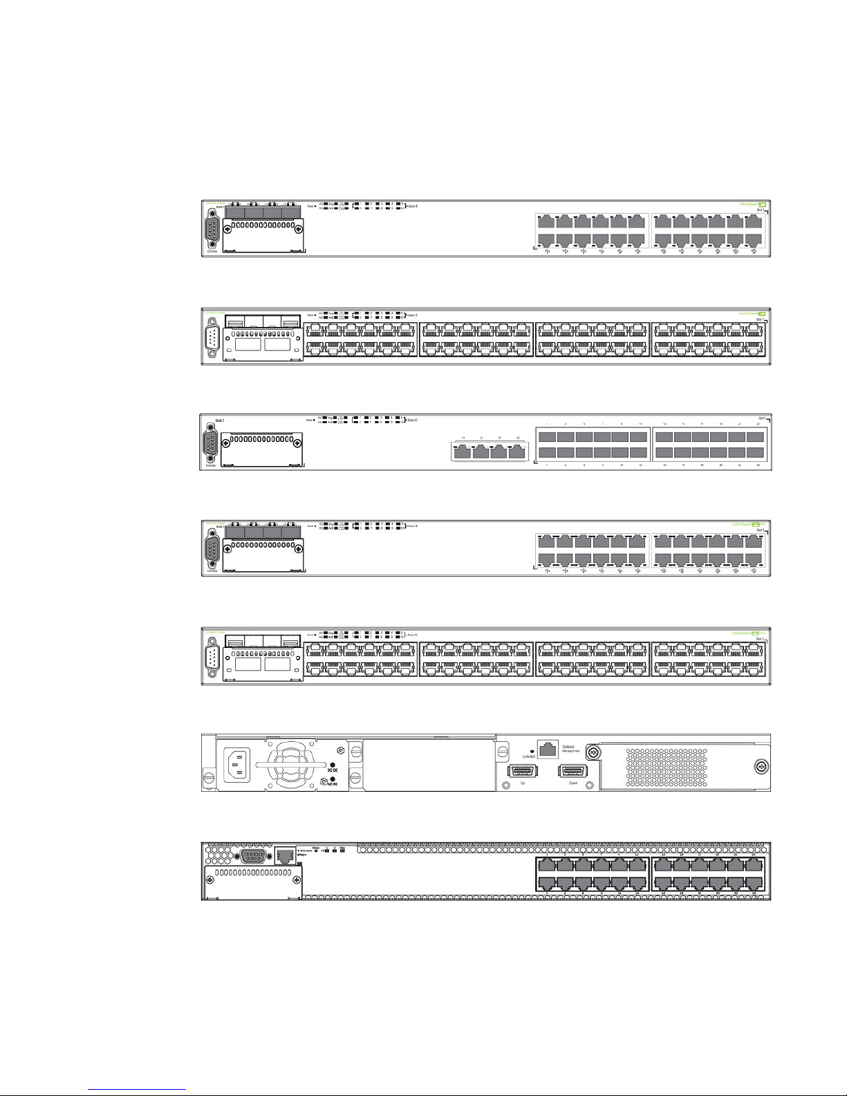
FIGURE 1 Brocade FCX 624S front panel
FIGURE 2 Brocade FCX 648S front panel
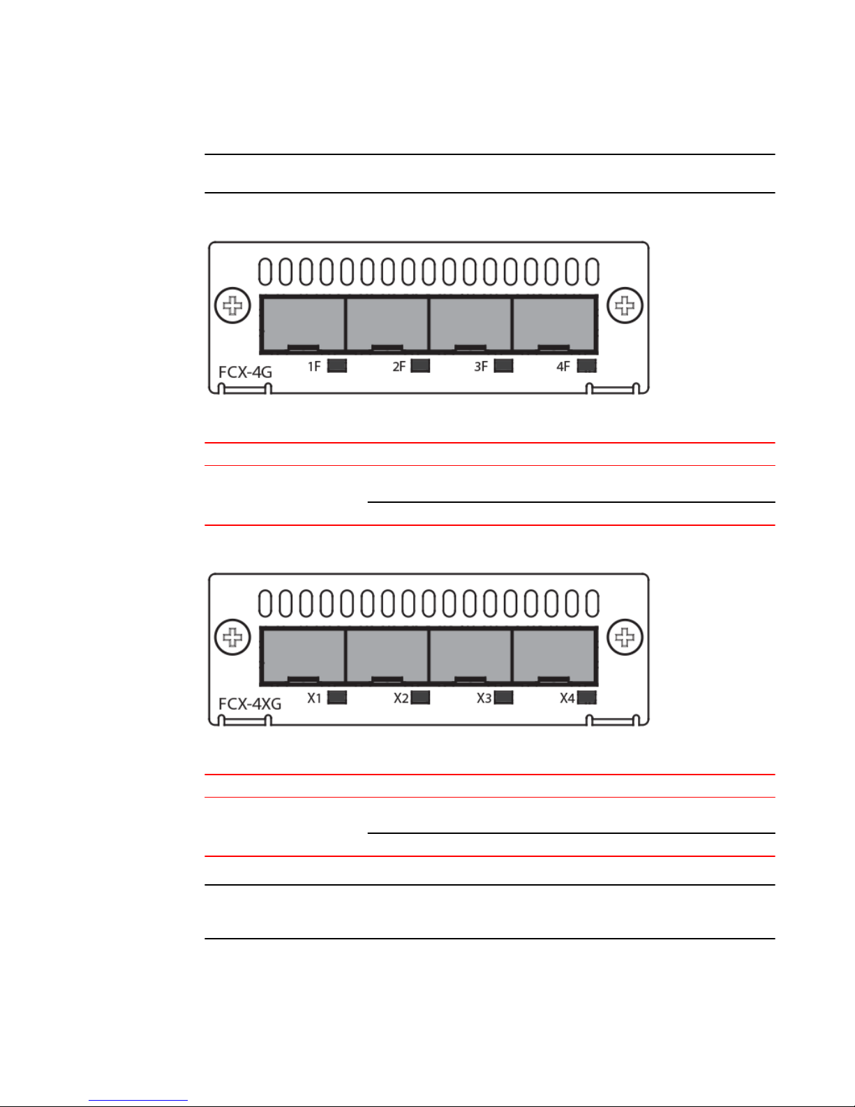
FIGURE 3 Brocade FCX 624S-F front panel
FIGURE 4 Brocade FCX 624S-HPOE front panel
FIGURE 5 Brocade FCX 648S-HPOE front panel
FIGURE 6 Brocade FCX 648S-HPOE rear panel
FIGURE 7 Brocade FCX 624-E front panel
FIGURE 8 Brocade FCX 624-I front panel
Brocade FCX Series Hardware Installation Guide 13
53-1002977-01
Page 16
Product Overview
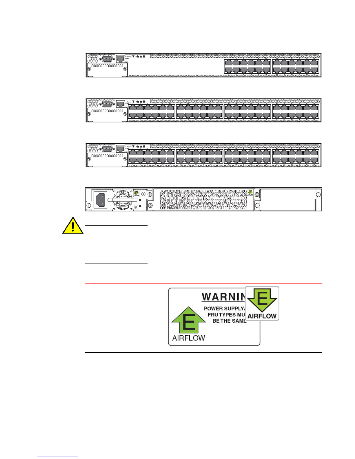
FIGURE 9 Brocade FCX 648-E front panel
FIGURE 10 Brocade FCX 648-I front panel
FIGURE 11 Brocade FCX 624-E, FCX 624-I, FCX 648-E, and FCX 648-I rear panels
CAUTION
For the Brocade FCX 624-E, FCX 624-I, FCX 648-E, and FCX 648-I devices, be sure that the
airflow direction of the power supply unit matches that of the installed resiliant quad-fan fan
tray. The power supplies and fan trays are clearly labeled with either a green arrow with an "E",
or an orange arrow with an "I".
Device Label on required power supply Label on required fan tray
Brocade FCX 624-E and Brocade
FCX 648-E
14 Brocade FCX Series Hardware Installation Guide
53-1002977-01
Page 17

Control features
Device Label on required power supply Label on required fan tray
Brocade FCX 624-I and Brocade
FCX 648-I
Control features
Each device front panel includes the following control features:
• Serial management interface (the DB9 port labeled Console )
• Out-of-band RJ45 management Interface
Serial management interface (DB9 Console port)
The serial management interface allows you to configure and manage the device using a third-party
terminal emulation application on a directly-connected PC. A straight-through EIA or TIA DB9 serial
cable (M or F) ships with the device. The serial management interface (the DB9 Console port) is located
in the left corner of the front panel.
Out-of-band RJ45 management interface
The out-of-band RJ45 management interface enables you to configure and manage the device using a
third-party terminal emulation application on a directly-connected PC.
Network interfaces for Brocade FCX 624S, FCX 648S, FCX 624S-F, FCX 624S-HPOE, and FCX
648S-HPOE
FCX devices contain the following interfaces:
• 10/100/1000 Mbps ports with RJ45 copper connectors
• 100/1000 Mbps ports with mini-GBIC slots for SFP MSA-compliant fiber transceivers
• Optional 2-port 10Gbps Ethernet XFP module
• CX4 stacking ports
NOTE
Brocade recommends that you refer to Cable specifications before connecting a cable to any of the
ports.
Network interfaces for Brocade FCX 624-E, FCX 624-I, FCX 648-E, and FCX 648-I
FastIron CX devices contain the following interfaces:
Brocade FCX Series Hardware Installation Guide 15
53-1002977-01
Page 18

Product Overview
• 10/100/1000 ports with RJ45 copper connectors
• 100/1000 ports with mini-GBIC slots for MSA-compliant SFP transceivers
• Optional 4-port 1Gbps Ethernet SFP module
• Optional 4-port 10Gbps Ethernet SFP+ module
NOTE
Brocade recommends that you refer to Cable specifications before connecting a cable to any of the
ports.
FastIron CX 10/100/1000 BASE-T ports
All FastIron CX devices except for the fiber models contain 24 or 48 RJ45 ports that operate at 10
Mbps or 100 Mbps, half or full duplex, or at 1000 Mbps, full duplex. FCX fiber models contain 24 SFP
ports. Because all ports support automatic MDI or MDI-X operation, you can use straight-through
cables for all network connections to PCs or servers, or to other switches or hubs. In addition, it is
ideal and preferred to use straight-through cable for switch-to-switch connections.
Each of these ports supports auto-negotiation, so the optimum transmission mode (half or full duplex),
and the data rate (10, 100, or 1000 Mbps) can be selected automatically. If a device connected to one
of these ports does not support auto-negotiation, the communication mode of the port can be
configured manually.
Combination ports
FCX devices contain four combination ports, which are four Small Form Factor Pluggable (SFP)
network interfaces (1F~4F) that are shared with four of the RJ45 ports (ports 1~4). In the default
configuration, if an SFP transceiver is installed in a slot and has a valid link on its port, the associated
RJ45 port is disabled and cannot be used. The switch can also be configured to force the use of a
combination RJ45 port or SFP slot, as required.
NOTE
Brocade FCX 624-E, FCX 624-I, FCX 648-E, and FCX 648-I devices do not ship with SFP ports. You
must install the optional SFP module for SFP support.
Slot locations
There are three slot locations on Brocade FCX Series devices: slots 3 and 1 on the front panel and
slot 2 on the rear panel.
FIGURE 12 Slot locations on the front panel of Brocade FCX Series devices
16 Brocade FCX Series Hardware Installation Guide
53-1002977-01
Page 19
1. Slot 3
2. Slot 1
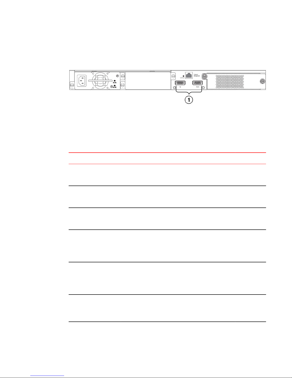
FIGURE 13 Slot location on the rear panel of Brocade FCX Series devices
1. Slot 2 (default stacking ports)
Slot designations
The slot designations for FCX models:
Stack unit slots for FCX stackable devices TABLE 2
Product Overview
Device Slot 1 Slot 2 Slot 3
Brocade FCX 624S 20 10/100/1000 Mbps ports plus 4
Combo ports (RJ45 ports 1-4, or SFP
ports 1F-4F)
Brocade FCX 648S 44 20 10/100/1000 Mbps ports plus 4
Combo ports (RJ45 ports 1-4, or SFP
ports 1F-4F)
Brocade FCX 624S-F 20 100/1000 Mbps SFP ports plus 4
Combo ports 10/100/1000 Mbps RJ45
on front panel
Brocade FCX 624-E and
Brocade FCX 624-I devices
with optional 4-port 1 Gbps
SFP module
Brocade FCX 648-E and
Brocade FCX 648-I devices
with optional 4-port 1 Gbps
SFP module
20 10/100/1000 Mbps RJ45 ports, plus
4-port 1 Gbps SFP module (optional
module) combined with the first four
10/100/1000 Mbps RJ45 copper ports
(acting as a Combo port).
44 10/100/1000 Mbps RJ45 ports, plus
4-port 1 Gbps SFP module (optional)
combined with the first four
10/100/1000 Mbps RJ45 copper ports
(acting as a Combo port).
2-port 16 Gbps CX4
stacking module on rear
panel
2-port 16 Gbps CX4
stacking module on rear
panel
2-port 16 Gbps CX4
stacking module on rear
panel
N/A N/A
N/A N/A
2-port 10 Gbps
XFP module
2-port 10 Gbps
XFP module
2-port 10 Gbps
XFP module
Brocade FCX 624-E and
Brocade FCX 624-I devices
with optional 4-port 10 Gbps
SFP+ module
Brocade FCX Series Hardware Installation Guide 17
53-1002977-01
24 10/100/1000 Mbps RJ45 ports 4-port 10 Gbps SFP+
module on front panel
(optional module)
N/A
Page 20

SFP interfaces
Stack unit slots for FCX stackable devices (Continued)TABLE 2
Device Slot 1 Slot 2 Slot 3
Brocade FCX 648-E and
Brocade FCX 648-I devices
with optional 4r-port 10 Gbps
SFP+ module
48 10/100/1000 Mbps RJ45 ports 4-port 10 Gbps SFP+
module on front panel
(optional module)
N/A
SFP interfaces
This section describes the network interfaces supported on FCX devices. For information about
supported SFP and SFP+ transceivers, refer to the following Brocade website:
http://www.brocade.com/downloads/documents/data_sheets/product_data_sheets/Optics_DS.pdf
SFP network interfacesTABLE 3
Interface Show Media Description
1000Base-BX-D M-GBXD
1000Base-BX-U M-GBXU
1000Base-LHA M-LHA
1000Base-LHB M-LHB
1000Base-LX M-LX
1000Base-LH M-LH
1000Base-SX M-SX
1000Base-T C
100Base-T C**
10Base-T C**
100Base-FX M-FX
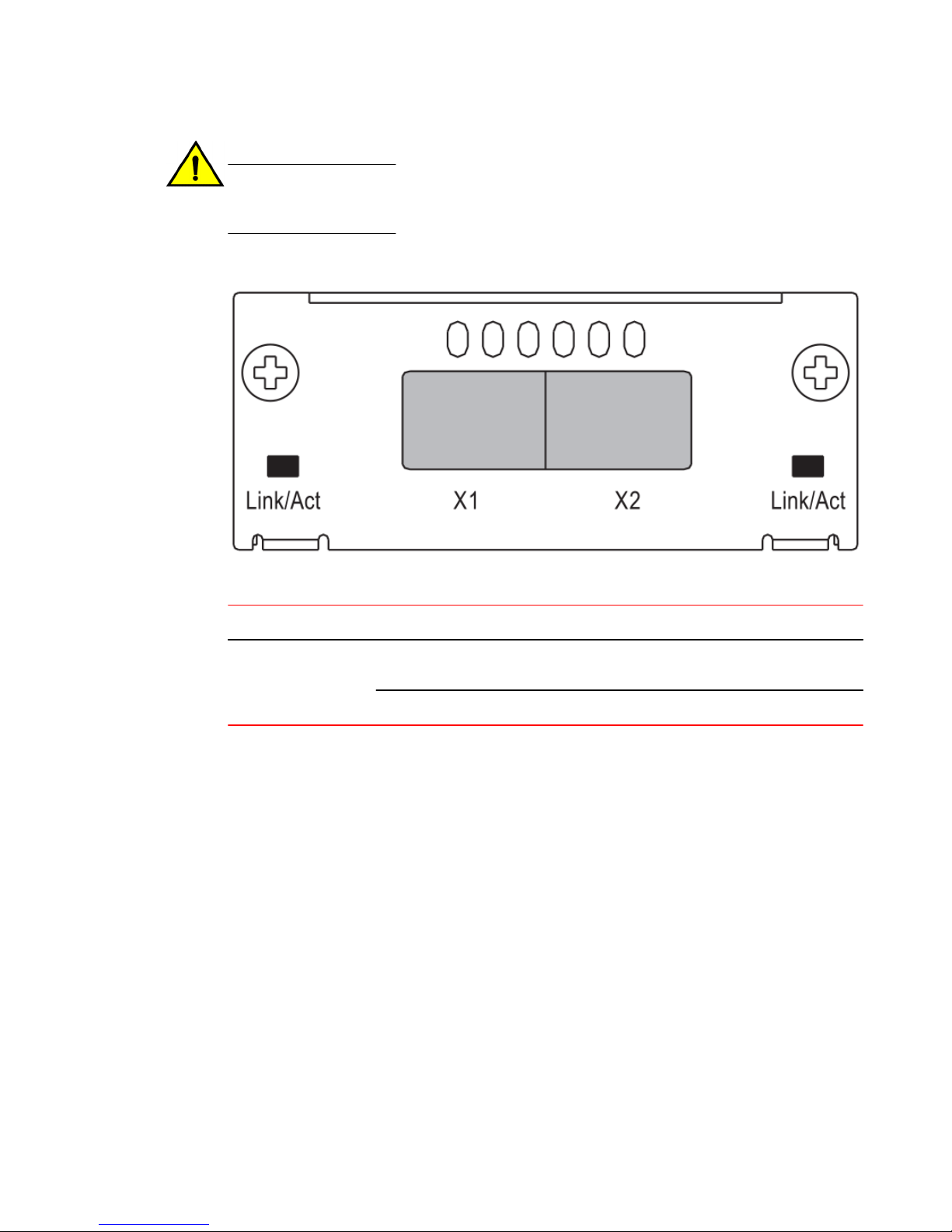
Optional two-port 10 Gbps XFP uplink module
The Brocade FCX 624S, FCX 648S, FCX 624S-F, FCX 624S-HPOE, and FCX 648S-HPOE devices
include a slot on the front panel for a two-port 10 Gbps XFP uplink module. This module operates at
10 Gbps full duplex.
18 Brocade FCX Series Hardware Installation Guide
53-1002977-01
Page 21
NOTE
The 10 Gbps XFP module is not hot-swappable.
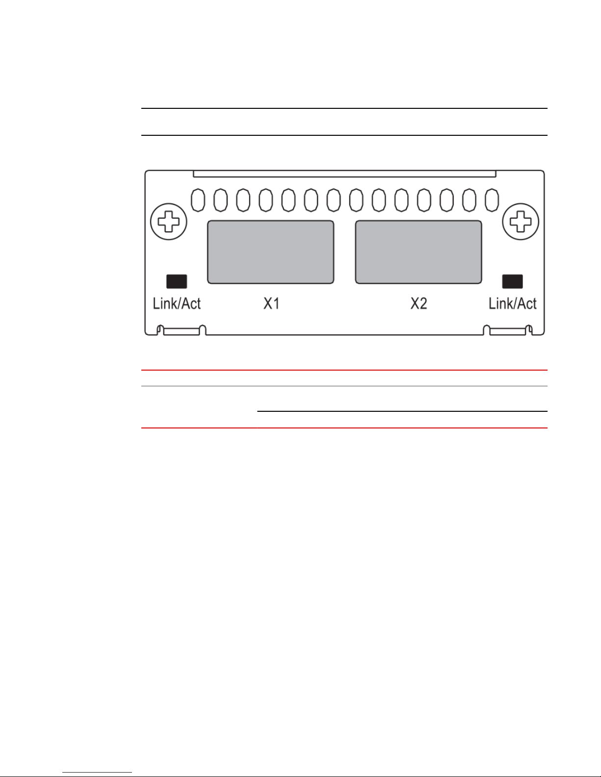
FIGURE 14 Two-port 10 Gbps XFP module
Optional 4x1G SFP+ and 4x10G SFP+ modules
Two-port 10 Gbps XFP module port status LEDsTABLE 4
LED Condition Status
Link or Act LED (Link or
Activity)
On or flashing Green Port has a valid link at 10 Gbps. Flashing
indicates activity.
Off The link is down.
Optional 4x1G SFP+ and 4x10G SFP+ modules
The Brocade FCX 624-E, FCX 624-I, FCX 648-E, and FCX 648-I devices include a slot on the front
panel for a four-port 1 Gbps SFP module, or a four-port 10 Gbps SFP+ module. The 1 Gbps SFP
module operates at 1 Gbps full duplex, and the 10 Gbps SFP+ module operates at 10 Gbps full duplex.
FCX-I and FCX-E devices can be used in a homogeneous stack by installing the optional 4-port 10
Gbps SFP+ module, and connecting devices using standard duplex LC cables. These devices cannot
be combined in a stack with non-FCX devices. For detailed information about how to configure FCX
devices in a homogeneous stack, see the FastIron Ethernet Switch Stacking Configuration Guide .
Brocade FCX Series Hardware Installation Guide 19
53-1002977-01
Page 22
Product Overview
NOTE
The 1 Gbps SFP and 10 Gbps SFP+ modules are not hot-swappable.
FIGURE 15 Four-port 1 Gbps SFP module
Four-port 1 Gbps SFP module status LEDs TABLE 5
LED Condition Status
Link or Act LED (Link or
Activity)
On or flashing Green Port has a valid link at 1 Gbps. Flashing
indicates activity.
Off The link is down.
FIGURE 16 Four-port 10 Gbps SFP+ module
Four-port 10 Gbps SFP+ module status LEDs TABLE 6
LED Condition Status
Link or Act LED (Link or
Activity)
On or flashing Green Port has a valid link at 10 Gbps. Flashing
indicates activity.
Off The link is down.
NOTE
The two left ports on the SFP+ module do not pass regular Ethernet traffic by default. The stack
disable CLI command must be configured on these two ports in order for them to pass regular traffic.
20 Brocade FCX Series Hardware Installation Guide
53-1002977-01
Page 23

16/10 Gbps Ethernet CX4 stacking module
16/10 Gbps Ethernet CX4 stacking module
The Brocade FCX 624S, FCX 648S, FCX 624S-F, FCX 624S-HPOE, and FCX 648S-HPOE devices
include two 16/10 Gbps Ethernet CX4 ports on the rear panel (the stacking ports). The device can
perform data transmission directly through copper links of up to 3 meters.
The Up Link and Down Link LEDs on the front panel indicate operational status. If the Up Link or Down
Link LED is on, the port is connected. If the Up Link or Down Link LED is off, no connection exists, or
the link is down.
Cable specifications for CX4 stacking ports
The following cable specifications apply to the CX4 stacking ports:
• Support for 802.3ak or 10 Gbps Ethernet CX4 standard and 16 Gbps inter-unit stacking (up to 8
units in a stack)
• Support for cables up to 3 meters in length
• Requires latch-style receptacle or SFF-8470 plug
NOTE
Brocade FCX 624-E, FCX 624-I, FCX 648-E, and FCX 648-I devices can be added to a stack using the
first two ports on a four-port 10 Gbps SFP+ module (optional) using standard duplex LC cables.
Optional 2-port 10 Gbps SFP+ uplink module
The following Brocade FCX devices include a slot on the front panel for a two-port 10 Gbps SPF+ uplink
module. This module operates at 10 Gbps full duplex.
• Brocade FCX 624S
• Brocade FCX 648S
• Brocade FCX 624S-F
• Brocade FCX 624S-HPOE
• Brocade FCX 648S-HPOE
The 2-port 10 Gbps SPF+ uplink module can replace the 2-port XFP module in the fixed slot 3. Port
mapping is the same as for the 2x10 XFP with slot 3 and port 1 or 2, for example, 1/3/1 and 1/3/2.
Stacking is supported using the stack default-port command with the 1/3/1 and 1/3/2 options.
The module is named FCX-2SFPP 2-port 10G Module (2-SFP+) in configuration and output.
NOTE
Reload the device whenever you install or replace the module because the 2x10 SFP+ module is not
hot swappable.
Brocade FCX Series Hardware Installation Guide 21
53-1002977-01
Page 24
Product Overview
CAUTION
Power-down your device before you install or replace a module for safety purposes and to
avoid instability due to a delay in power cycling.
FIGURE 17 Two-port 10 Gbps SFP+ module
10 Gbps SFP+ module port status LEDs TABLE 7
LED Condition Status
Link or Act LED (Link or
Activity
On or flashing green Port has a valid link at 10 Gbps.
Flashing indicates activity.
Off The port is down.
22 Brocade FCX Series Hardware Installation Guide
53-1002977-01
Page 25

Modified CLI examples for the 2-port 10 Gbps SFP+ module
The following sample output from the show module command displays an entry
for the 2-port 10G SFP+ module.
device# show module
Module
Status Ports Starting MAC
U1:M1 FCX-48GS POE 48-port Management Module
OK 48 0024.38c9.4d00
U1:M2 FCX-2XGC 2-port 16G Module (2-CX4)
OK 2 0024.38c9.4d31
U1:M3 FCX-2SFPP 2-port 10G Module (2-SFP+)
OK 2 0024.38c9.4d33
The following sample output from the show version command shows that the 2port 10G SFP+ module is in slot 3.
device# show version
Copyright (c) 1996-2011 Brocade Communications Systems,
Inc.
UNIT 1: compiled on Oct 18 2012 at 16:01:04 labeled as
FCXS07300b1
(5373912 bytes) from Primary
FCXS07300b1.bin
SW: Version 07.3.00b1T7f1
Boot-Monitor Image size = 370663, Version:07.3.00T7f5
(grz07300b1)
HW: Stackable FCX648S-HPOE-PREM (PROM-TYPE FCX-ADV-U)
===========================================================
===============
UNIT 1: SL 1: FCX-48GS POE 48-port Management Module
Serial #: BCYXXXXXXXX
License: BASE_SOFT_PACKAGE (LID: deaHHJIhFNb)
P-ENGINE 0: type DB90, rev 01
P-ENGINE 1: type DB90, rev 01
PROM-TYPE: FCX-ADV-U
===========================================================
===============
UNIT 1: SL 2: FCX-2XGC 2-port 16G Module (2-CX4)
===========================================================
===============
UNIT 1: SL 3: FCX-2SFPP 2-port 10G Module (2-SFP+)
===========================================================
===============
800 MHz Power PC processor 8544E (version 0021/0022) 400
MHz bus
65536 KB flash memory
256 MB DRAM
STACKID 1 system uptime is 2 days 10 minutes 24 seconds
The system : started=warm start reloaded=by "reload"
The following is sample output of the show running-config command.
Product Overview
device# show running-config
!
Startup-config data location is flash memory
!
Startup configuration:
!
ver 07.3.00a001T7f1
!
stack unit 1
module 1 fcx-48-poe-port-management-module
module 2 fcx-cx4-2-port-16g-module
module 3 fcx-sfpp-2-port-10g-module
!
Brocade FCX Series Hardware Installation Guide 23
53-1002977-01
Page 26

Specifying a port address
The following is sample output of the show media and show optic commands
with some configuration.
device# show media
1/1/1:C 1/1/2:C 1/1/3:C 1/1/4:C 1/1/5:C
1/1/6:C 1/1/7:C 1/1/8:C
1/1/9:C 1/1/10:C 1/1/11:C 1/1/12:C 1/1/13:C
1/1/14:C 1/1/15:C 1/1/16:C
1/1/17:C 1/1/18:C 1/1/19:C 1/1/20:C 1/1/21:C
1/1/22:C 1/1/23:C 1/1/24:C
1/1/25:C 1/1/26:C 1/1/27:C 1/1/28:C 1/1/29:C
1/1/30:C 1/1/31:C 1/1/32:C
1/1/33:C 1/1/34:C 1/1/35:C 1/1/36:C 1/1/37:C
1/1/38:C 1/1/39:C 1/1/40:C
1/1/41:C 1/1/42:C 1/1/43:C 1/1/44:C 1/1/45:C
1/1/46:C 1/1/47:C 1/1/48:C
1/2/1:XG-CX4 1/2/2:XG-CX4
1/3/1:XG-SR 1/3/2:XG-SR
device# show media e 1/3/1
Port 1/3/1: Type : 10G XG-SR(SFP +)
Vendor: Brocade Version: 1
Part# : PLRXPLSCS4371 Serial#:
CXXXXXXXX
device(config)# op 1
Enable optical monitoring and set alarm/warn interval to
1 minute(s)
device(config)# show optic 1/3/1
Port Temperature Tx Power Rx Power Tx Bias
Current
+----+-----------+--------------+-------------+---------------+
1/3/1 32.7421 C -002.3195 dBm -002.5947 dBm 6.212 mA
Normal Normal Normal
Normal
device# show media e 1/3/1
Port 1/3/1: Type : 10G XG-ER(SFP +)
Vendor: BROCADE Version: A
Part# : 57-0000085-01 Serial#:
XXXXXXXXXXXXXXX
device# show media e 1/3/2
Port 1/3/2: Type : 10G XG-USR (SFP +)
Vendor: BROCADE Version: A
Part# : 57-1000130-01 Serial#:
XXXXXXXXXXXXXXX
device# show media
1/1/1:C 1/1/2:C 1/1/3:C 1/1/4:C 1/1/5:C
1/1/6:C 1/1/7:C 1/1/8:C
1/1/9:C 1/1/10:C 1/1/11:C 1/1/12:C 1/1/13:C
1/1/14:C 1/1/15:C 1/1/16:C
1/1/17:C 1/1/18:C 1/1/19:C 1/1/20:C 1/1/21:C
1/1/22:C 1/1/23:C 1/1/24:C
1/1/25:C 1/1/26:C 1/1/27:C 1/1/28:C 1/1/29:C
1/1/30:C 1/1/31:C 1/1/32:C
1/1/33:C 1/1/34:C 1/1/35:C 1/1/36:C 1/1/37:C
1/1/38:C 1/1/39:C 1/1/40:C
1/1/41:C 1/1/42:C 1/1/43:C 1/1/44:C 1/1/45:C
1/1/46:C 1/1/47:C 1/1/48:C
1/2/1:XG-CX4 1/2/2:XG-CX4
1/3/1:XG-ER 1/3/2:XG-USR
Specifying a port address
You can specify a port address for a data port, stacking port, or a management port.
24 Brocade FCX Series Hardware Installation Guide
53-1002977-01
Page 27
Port, system, and power status LEDs for Brocade FCX 624S, FCX 648S, FCX 624S-F, FCX 624S-HPOE, and FCX 648S-HPOE
Specifying a data port
The port address format is stack unit/slot/port, where:
• stack unit--Specifies the stack unit ID. Range is from 1 to 8. If the device is not part of a stack, the
stack unit ID is 1.
• slot--Specifies the slot number. Can be 1 or 3.
• port--Specifies the port number in the slot. Range is from 1 to 24 (24-port models) or 1 to 48 (48port models).
This example indicates it is Stack Unit 1:
Brocade(config)# interface ethernet 1/1/2
Specifying a stacking port
The port address format is stack unit/slot/port, where:
• stack unit--Specifies the stack unit ID. Range is from 1 to 8.
• slot--Specifies the slot number. Default stacking ports are in slot 2 (FCX S/S-F).
• port--Specifies the port number in the slot. Default stacking ports in slot 2 are ports 1 and 2.
This example shows how to specify port 2 in slot 2 of unit 3 in a stack:
Brocade(config)# interface ethernet 3/2/2
Specifying a management port
The management port number is always 1. This example shows how to specify the management port:
Brocade(config)# interface management 1
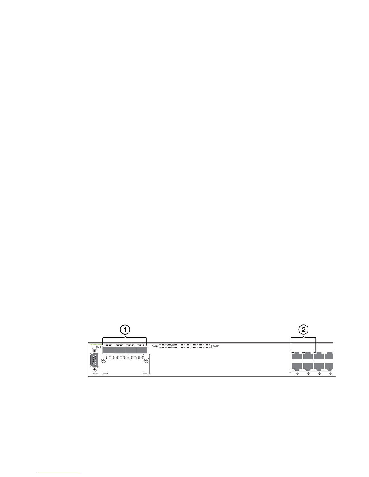
Port, system, and power status LEDs for Brocade FCX 624S, FCX 648S, FCX 624S-F, FCX
624S-HPOE, and FCX 648S-HPOE
FCX switches include a display panel for key system and port indicators that simplifies installation and
network troubleshooting. The LEDs are located on the front panel for easy viewing.
FIGURE 18 Port status LEDs
1. Port status LEDs
2. Port status LEDs
Brocade FCX Series Hardware Installation Guide 25
53-1002977-01
Page 28
Product Overview
Port status LEDs TABLE 8
LED Condition Status
Ethernet(1~24/48)
Link or Activity or Speed
HPOE(1~24/48) On Green The port is providing HPOE power to a connected device.
SFP(1F~4F)
Link or Activity
SFP(1F~4F)
Speed
On/Flashing Green The port has established a valid link at 1000 Mbps. Flashing
indicates the port is transmitting and receiving user packets.
On/Flashing Amber The port has established a valid link at 10 or 100 Mbps. Flashing
indicates the port is transmitting and receiving user packets.
Off A link is not established with a remote port.
Off The port is not providing HPOE power.
On/Flashing Green The SFP port has established a valid link. Flashing indicates the
port is transmitting and receiving user packets.
Off A link is not established with a remote port.
On Green The SFP port is operating at 1000 Mbps.
On Amber The SFP port is operating at 100 Mbps.
Off A link is not established with a remote port.
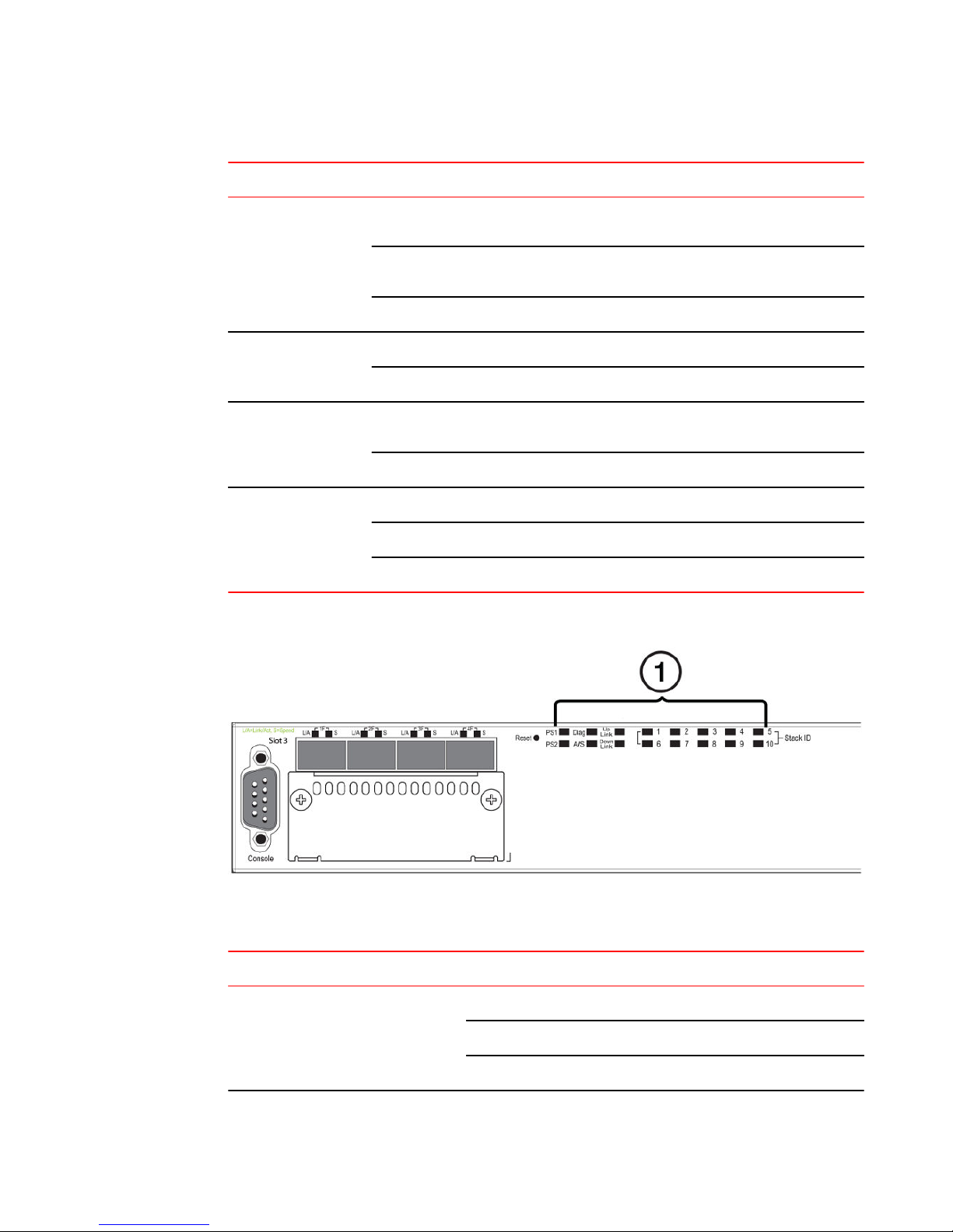
FIGURE 19 System status LEDs
1. System status LEDs
System status LEDs TABLE 9
LED Condition Status
PS1
PS2
(Power Supply Status)
26 Brocade FCX Series Hardware Installation Guide
Green Power supply is operating normally.
Amber Power supply fault.
Off Power off or failure.
53-1002977-01
Page 29
System status LEDs (Continued)TABLE 9
LED Condition Status
Product Overview
Diag
(Diagnostic)
A or S
(Active or Standby)
Up Link or Down Link (Stacking uplink or
downlink port status)
Stack ID (1-8) Green Indicates the device stack ID.
Flashing Green System self-diagnostic test in progress.
Green System self-diagnostic test successfully completed.
Amber System self-diagnostic test has detected a fault.
(Blower, thermal or any interface fault.)
Green The device is the Active controller. If this LED is
flashing green, the system is initializing.
Amber Indicates the device is the Standby controller.
Off Device is operating as a stack member, or is in
standalone mode.
Green Uplink is operating normally.
Off Uplink has failed or there is no link.
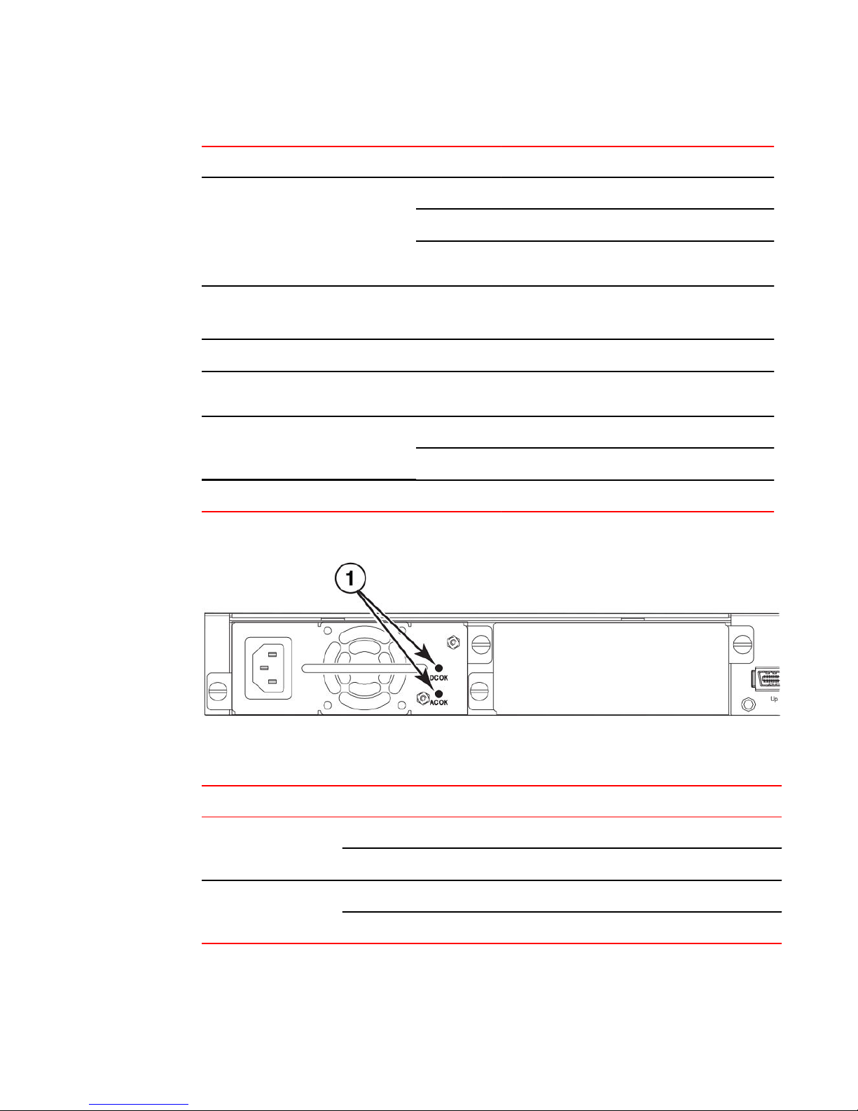
FIGURE 20 Power status LEDs
1. Power status LEDs
Power status LEDs TABLE 10
LED Condition Status
DC OK Green DC output ok
AC OK Green AC input ok
Brocade FCX Series Hardware Installation Guide 27
53-1002977-01
Red DC output fail
Off AC input fail
Page 30

Product Overview
NOTE
Both "AC OK" and "DC OK" LEDs must be green for the device to function normally.
Switch status for two installed power supply units TABLE 11
State LED PSU1 PSU2 Switch Status Load Sharing HPOE Budget(HPOE
Four Green PSU LEDs AC OK Green Green Running Yes 820W
DC OK Green Green
Single Red ‘DC OK’ LED AC OK Green Green Running No 410W
DC OK Green Red
Both ‘DC OK’ LEDs Red AC OK Green Green Failure No None
DC OK Red Red
One PSU with both ‘AC
OK’ ‘DC OK’ LEDs Off
‘DC OK’ LEDs Red and
Off
All ‘AC OK’ LEDs Off AC OK Off Off Power Off or
AC OK Green Off Running No 410W
DC OK Green Off
AC OK Green Off Failure No None
DC OK Red Off
No None
Failure
DC OK Off Off
models only)
NOTE
When two 620W power supplies are installed in an HPOE system that has no load or light load on the
POE function, one of two power supplies may have its "DC OK" LED light red. There is no fault in the
power supply or the system and the switch is functioning normally. The LED will turn to green
automatically once the load is increased over the minimum load requirement. In configurations with a
single power supply installed the "DC OK" LED will light green in a no-load or light-load condition.
28 Brocade FCX Series Hardware Installation Guide
53-1002977-01
Page 31

Port, system, and power status LEDs for Brocade FCX 624-E, FCX 624-I, FCX 648-E, and FCX 648-I
Port, system, and power status LEDs for Brocade FCX 624-E, FCX 624-I, FCX 648-E, and FCX
648-I
FCX switches include a display panel for key system and port indicators that simplifies installation and
network troubleshooting. The LEDs are located on the front panel for easy viewing.
FIGURE 21 Port status LEDs
1. Port status LEDs
2. SFP or SFP+ port status LEDs
Port status LEDs TABLE 12
LED Condition Status
Ethernet(1~24/48)
Link or Activity or Speed
SFP(1F~4F)
Link or Activity
SFP+(1F~4F)
Link or Activity
On/Flashing Green The port has established a valid link at 10/100/1000 Mbps. Flashing
indicates the port is transmitting and receiving user packets.
Off A link is not established with a remote port.
On/Flashing Green The SFP port has established a valid 100/1000 Mbps link. Flashing
indicates the port is transmitting and receiving user packets.
Off A link is not established with a remote port.
On/Flashing Green The SFP+ port has established a valid 10 Gbps link. Flashing
indicates the port is transmitting and receiving user packets.
Brocade FCX Series Hardware Installation Guide 29
53-1002977-01
Page 32

Product Overview
Port status LEDs TABLE 12
LED Condition Status
Off A link is not established with a remote port.
FIGURE 22 System status LEDs
1. System status LEDs
System status LEDs TABLE 13
LED Condition Status
PS1
PS2
(Power Supply Status)
Diag
(Diagnostic)
Out-of-band ManagementLink or
Activity
Green Power supply is operating normally. It is installed
properly and the power cord is attached to a power
source.
Amber Power supply fault. The power supply may not be
installed properly.
Off Power off or failure.
Flashing Green System self-diagnostic test in progress.
Green System self-diagnostic test successfully completed.
Amber System self-diagnostic test has detected a fault.
(Blower, thermal or any interface fault.)
On/Flashing Green The port has established a valid link at 10/100/1000
Mbps. Flashing indicates the port is transmitting and
receiving user packets.
Off A link is not established with a remote port.
FIGURE 23 Power status LEDs
30 Brocade FCX Series Hardware Installation Guide
53-1002977-01
Page 33

1. Power status LEDs
Power status LEDs TABLE 14
LED Condition Status
DC OK Green DC output ok
Red DC output fail
Product Overview
AC OK Green AC input ok
Off AC input fail
NOTE
Both "AC OK" and "DC OK" LEDs must be green for the device to function normally.
Switch status for two installed power supply units TABLE 15
State LED PSU1 PSU2 Switch Status Redundancy
Four Green PSU LEDs AC OK Green Green Running Yes
DC OK Green Green
Single Red ‘DC OK’ LED AC OK Green Green Running No
DC OK Green Red
Both ‘DC OK’ LEDs Red AC OK Green Green Failure No
DC OK Red Red
One PSU with both ‘AC OK’ ‘DC OK’ LEDs Off AC OK Green Off Running No
‘DC OK’ LEDs Red and Off AC OK Green Off Failure No
All ‘AC OK’ LEDs Off AC OK Off Off Power Off or Failure No
Brocade FCX Series Hardware Installation Guide 31
53-1002977-01
DC OK Green Off
DC OK Red Off
Page 34

Power supplies
Switch status for two installed power supply units (Continued)TABLE 15
State LED PSU1 PSU2 Switch Status Redundancy
DC OK Off Off
Power supplies
The device has two power receptacles on the rear panel. Each device ships with one power supply
installed. Brocade FCX 624S, FCX 648S, FCX 624S-F, FCX 624-E, FCX 624-I, FCX 648-E and FCX
648-I devices use a 210W PSU. Brocade FCX 624S-HPOE and Brocade FCX 648S-HPOE devices
use a 620W PSU.
Each power supply has one standard power receptacle for the AC power cable, and AC and DC status
LEDs for easy monitoring and troubleshooting.
A secondary power supply can be installed to provide backup power in case of a failure and for loadbalancing when both power suppies are operational.Load-balancing gives the power supplies a longer
life span. Both 210W and 620W PSUs are hot-swappable.
For instructions on installing and replacing a power supply refer to Installing and replacing a power
supply unit.
FIGURE 24 Brocade FCX 624-E, FCX 624-I, FCX 648-E, and FCX 648-I AC power supply receptacle
1. AC power receptacle
Power supply unit operation
When only one PSU is installed, both "AC OK" and "DC OK" LEDs on the installed PSU must be green
for the FCX device to function normally.
When two PSUs are installed, both "AC OK" and "DC OK" LEDs for one of the installed PSUs must be
green for the FCX device to function normally.
HPOE and HPOE + power supplies
Brocade FCX 624S-HPOE and Brocade FCX 648S-HPOE devices use a 620W PSU. When one PSU
is powering the switch, the HPOE budget is 410W. If both PSUs are installed and powering the switch,
each PSU provides 410W to the switch, increasing the HPOE budget to 820W.
32 Brocade FCX Series Hardware Installation Guide
53-1002977-01
Page 35

Installing the FCX Switch
● Unpacking the device......................................................................................................33
● Installation tasks..............................................................................................................34
● Installation precautions................................................................................................... 35
● Preparing the installation site.......................................................................................... 36
● Connecting devices in a traditional stack........................................................................ 41
● Powering on the system..................................................................................................48
● Attaching a PC or terminal.............................................................................................. 49
● Installing and replacing a power supply unit................................................................... 50
● Installing or replacing fan trays....................................................................................... 52
● Installing an optional module ..........................................................................................53
CAUTION
The procedures in this manual are intended for qualified service personnel.
CAUTION
Before beginning the installation, see the precautions in Power precautions on page 35.
Unpacking the device
FCX devices ship with all of the items listed below. Verify the contents of your shipping container. If any
items are missing, please contact the place of purchase.
Package contents
The following items are included in your shipping carton:
• FCX device
• 115V AC power cable (for AC sourced devices)
• FCX-S and FCX-F devices ship with a .5M CX-4 stacking cable
• Rack mount brackets
• Warranty card
• A straight-through EIA or TIA DB-9 serial cable (F/F). The serial cable can be ordered separately
from Brocade Communication Systems, Inc. If you prefer to build your own cable, see the pinout
information in Attaching a PC or terminal on page 49.
General requirements
To manage the system, you need a management station, such as a PC running a terminal emulation
application. Connect the management station to the Console serial port on the switch.
Brocade FCX Series Hardware Installation Guide
53-1002977-01
33
Page 36

Installation tasks
Use the serial connection to perform basic configuration tasks, including assigning an IP address and
network mask to the system. This information is required to manage the system using the Brocade
Network Advisor or using the CLI through Telnet.
Installation tasks
Follow the steps listed in this section to install your device. Details for each of these steps are provided
on the pages indicated.
Installation tasks TABLE 16
Task Number Task Where to Find More
1 Ensure that the physical environment that will host the device
has the proper cabling and ventilation.
2 Install any required optional modules into the switch. Powering on the system on
3 Install the Brocade device on a desktop, in an equipment rack. Installing the device on page
4 Once the device is physically installed, plug the device into a
nearby power source that adheres to the regulatory
requirements outlined in this manual.
5 Attach a terminal or PC to the Brocade device. This will enable
you to configure the device through the Command Line
Interface (CLI).
6 No default password is assigned to the CLI. For additional
access security, assign a password.
7 Before attaching equipment to the device, you need to
configure an interface IP address to the subnet on which it will
be located. Initial IP address configuration is performed using
the CLI with a direct serial connection.
Information
Preparing the installation site on
page 36
page 48
37
Powering on the system on
page 48
Attaching a PC or terminal on
page 49
Assigning permanent
passwords
Configuring IP addresses
8 Once you power on the device and assign IP addresses, the
9 Test IP connectivity to other devices by pinging them and
10 Continue configuring the device using the CLI. You can also
11 Secure access to the device. FastIron Ethernet Swich Secuity
34 Brocade FCX Series Hardware Installation Guide
system is ready to accept network equipment.
tracing routes.
use Brocade Network Advisor to manage the device.
Installing the device on page
37
Testing connectivity
Brocade Network Advisor
Guide
53-1002977-01
Page 37

Installation precautions
Follow all precautions when installing a Brocade device.
General precautions
CAUTION
All fiber-optic interfaces use Class 1 lasers.
CAUTION
Do not install the device in an environment where the operating ambient temperature might
exceed 40 ο C (104 ο F).
Installation precautions
CAUTION
Make sure the air flow around the front and sides of the device is not restricted.
CAUTION
Never leave tools inside the device.
Lifting precautions
CAUTION
Make sure the rack or cabinet housing the device is adequately secured to prevent it from
becoming unstable or falling over.
Power precautions
CAUTION
Use a separate branch circuit for each AC power cord, which provides redundancy in case one
of the circuits fails.
CAUTION
To avoid high voltage shock, do not open the device while the power is on.
Brocade FCX Series Hardware Installation Guide 35
53-1002977-01
Page 38

Preparing the installation site
CAUTION
Ensure that the device does not overload the power circuits, wiring, and over-current
protection. To determine the possibility of overloading the supply circuits, add the ampere
(amp) ratings of all devices installed on the same circuit as the device. Compare this total with
the rating limit for the circuit. The maximum ampere ratings are usually printed on the devices
near the input power connectors.
CAUTION
Disconnect the power cord from all power sources to completely remove power from the
device.
CAUTION
Before plugging a cable to any port, be sure to discharge any static charge stored on the cable
by touching the electrical contacts to ground surface.
CAUTION
If the installation requires a different power cord than the one supplied with the device, make
sure you use a power cord displaying the mark of the safety agency that defines the
regulations for power cords in your country. The mark is your assurance that the power cord
can be used safely with the device.
Preparing the installation site
Cabling infrastructure
Ensure that the proper cabling is installed at the site. Refer to Hardware specifications or
www.brocade.com for a summary of supported cabling types and their specifications.
Installation location
Before installing the device, plan its location and orientation relative to other devices and equipment.
Switches can be mounted in a standard 19-inch equipment rack that meets EIA-310D standards, or on
a flat surface. Be sure to follow the guidelines below when choosing a location.
The site should meet the following requirements:
• Maintain temperatures within 0 to 40 ο C (32 to 104 ο F) and humidity levels within 5% to 95%,
non-condensing.
• Allow a minimum of 3 in. of space between the sides and the back of the device and walls or other
obstructions for proper air flow.
36 Brocade FCX Series Hardware Installation Guide
53-1002977-01
Page 39

Installing the device
• Allow at least 3 in. of space at the front and back of the device for the twisted-pair, fiber-optic, and
power cabling.
• Be accessible for installing, cabling and maintaining the devices.
• Allow the status LEDs to be clearly visible.
• Allow for twisted-pair cable to be always routed away from power lines, fluorescent lighting fixtures
and other sources of electrical interference, such as radios and transmitters.
• Allow for the unit to be connected to a separate grounded power outlet that provides 110 to 240
VAC, 50 to 60 Hz, is within 2 m (6.6 feet) of each device and is powered from an independent
circuit breaker. As with any equipment, a filter or surge suppressor is recommended.
Installing the device
You can install Brocade devices on a desktop or in an equipment rack.
CAUTION
Make sure the rack or cabinet housing the device is adequately secured to prevent it from
becoming unstable or falling over.
Desktop installation
FIGURE 25 Attaching the adhesive feet
1. Attach the four adhesive feet to the bottom of the first switch.
2. Set the device on a flat desktop, table, or shelf near an AC power source. Make sure that adequate
ventilation is provided for the system. A 3 inch clearance is recommended on each side.
3. If installing a single switch only, refer to Powering on the system on page 48.
4. If installing multiple switches, attach the adhesive feet to each one. Place each device squarely on
top of the one below, in any order.
Brocade FCX Series Hardware Installation Guide 37
53-1002977-01
Page 40

Rack mount installation
Rack mount installation
NOTE
You need a #2 Phillips screwdriver for installation.
Before mounting the switch in a rack, pay particular attention to the following factors:
• Temperature: Since the temperature within a rack assembly may be higher than the ambient room
temperature, check that the rack-environment temperature is within the specified operating
temperature range.
• Mechanical loading: Do not place any equipment on top of a rack-mounted unit.
• Circuit overloading: Be sure that the supply circuit to the rack assembly is not overloaded.
• Grounding: Rack-mounted equipment should be properly grounded. Particular attention should be
given to supply connections other than direct connections to the mains.
Use the following setps to mount devices in rack.
1. Remove the rack mount kit from the shipping carton. The kit contains two L-shaped mounting
brackets and mounting screws.
2. Attach the mounting brackets to the sides of the device.
38 Brocade FCX Series Hardware Installation Guide
53-1002977-01
Page 41

Installing the FCX Switch
NOTE
FCX624-E, FCX624-I, FCX648-E, and FCX648-I device brackets are mounted using three screws.
FIGURE 26 Attaching the brackets for the Brocade FCX 624S, FCX 648S, FCX 624S-F, FCX
624S-HPOE, and FCX 648S-HPOE devices
FIGURE 27 Attaching the brackets for the FCX624-E, FCX624-I, FCX648-E, and FCX648-Idevices
Brocade FCX Series Hardware Installation Guide 39
53-1002977-01
Page 42

Installing the FCX Switch
40 Brocade FCX Series Hardware Installation Guide
53-1002977-01
Page 43

3. Attach the device in the rack.
FIGURE 28 Installing the device in a rack
Connecting devices in a traditional stack
4. If installing a single switch only, proceed to Powering on the system on page 48.
5. If installing multiple switches, mount them in the rack, one below the other, in any order.
Connecting devices in a traditional stack
Brocade FCX Series devices can operate as standalone devices and also as members of traditional
stacks. A stack is a group of devices--Brocade stackable units and their connected stacking links--that
are connected so that the stack is managed as a single entity.
A traditional stack contains devices from only one model in a product family. A traditional stack can
contain FCX S, FCX S-F, FCS E, and FCX I devices.
Stacking ports
This section summarizes the default stacking ports and the ports that can be used as stacking ports on
Brocade FCX Series devices. Default stacking ports have the capability to accept special stacking
packets during a CLI-initiated command sequence of the Secure Setup utility. Stacking ports can also
be used as data ports.
Brocade FCX Series Hardware Installation Guide 41
53-1002977-01
Page 44

Installing the FCX Switch
The default stacking ports on FCX S/S-F devices are the ports in the 16/10 Gbps CX4 stacking
module on the rear panel. The default stacking ports on the FCX E/I devices are the first two ports in
the four-port 10 Gbps SFP+ module on the front panel.
Refer to the table below for the list of supported XFP transceivers (for stacking and non-stacking FCX
models) and supported SFP and SFP+ transceivers.
FCX S/S-F
16/10 Gbps
CX4 stacking
module
2-port 10
Gbps XFP
module
FCX E/I
Stacking ports on Brocade FCX Series devicesTABLE 17
Stacking ports Data ports
Panel/slot Ports Default
stacking
Rear/2 1,2 Yes: 1, 2 Yes
Front/3 1,2 Yes: 1, 2 Yes: 1, 2
Can be data
ports
Default data Can be
stacking
ports
42 Brocade FCX Series Hardware Installation Guide
53-1002977-01
Page 45
Installing the FCX Switch
Stacking ports on Brocade FCX Series devicesTABLE 17
Stacking ports Data ports
4-port 10
Gbps SFP+
module
Panel/slot Ports Default
Front/2 1-4 Yes: 1, 2 Yes Yes: 3, 4 Yes
stacking
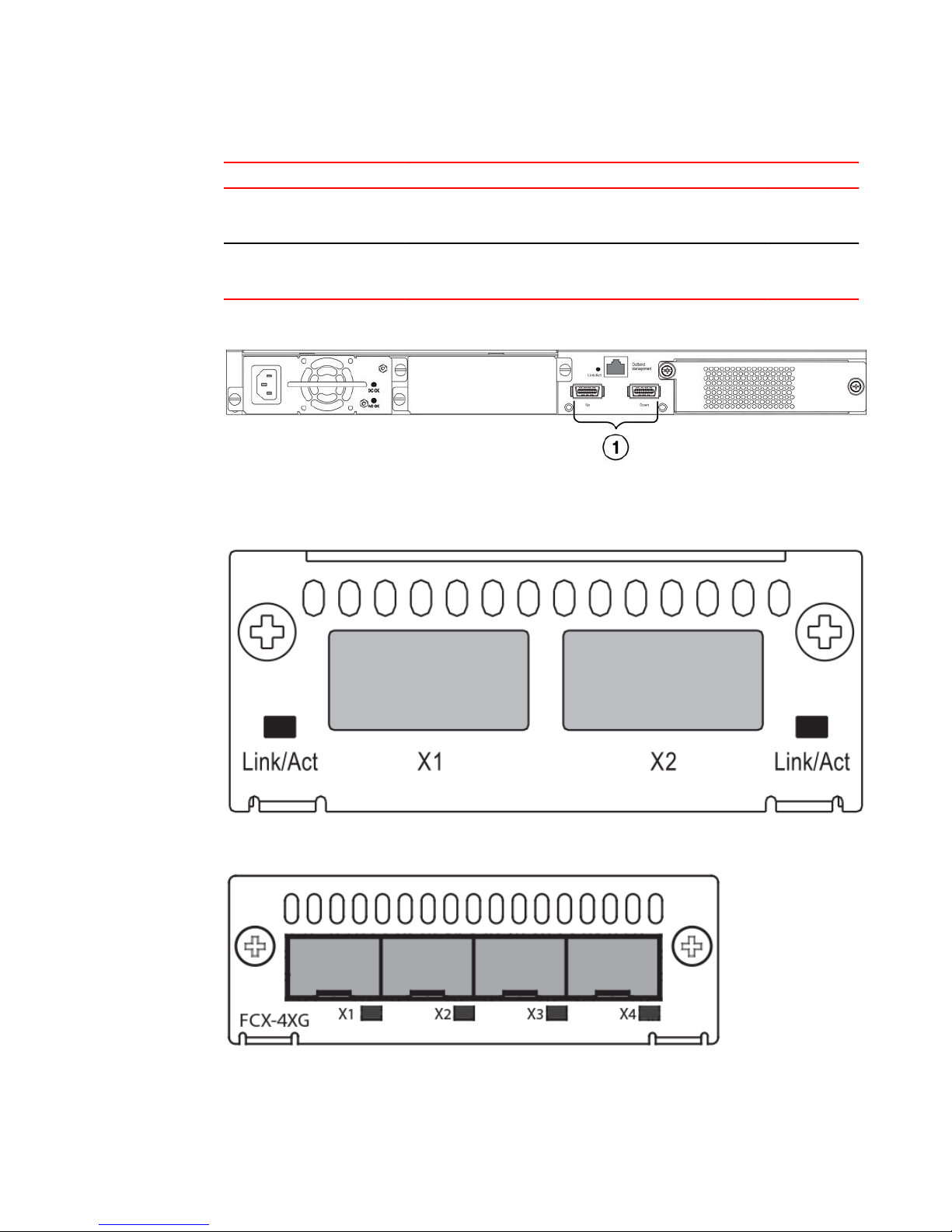
FIGURE 29 16/10 Gbps CX4 stacking module on the rear panel of FCX S/S-F devices
1. 16/10 Gbps CX4 stacking ports
Can be data
ports
Default data Can be
stacking
ports
FIGURE 30 Two-port 10 Gbps XFP module on the front panel of FCX S/S-F devices
FIGURE 31 Four-port 10 Gbps SFP+ module on the front panel of FCX E/I devices
To connect FCX E/I devices and FCX S/S-F devices in a stack, you connect a 10 Gbps module on one
device to a 10 Gbps module on anther device. You cannot connect the 4-port 10 Gbps SFP+ module
(FCX E/I) to the 16/10 Gbps CX4 stacking module (FCX S/S-F).
Brocade FCX Series Hardware Installation Guide 43
53-1002977-01
Page 46

Stacking configuration requirements
Modules that connect FCX E/I and FCX S/S-F devices in a stackTABLE 18
This FCX E/I module connects to These FCX S/S-F modules
4-port 10 Gbps SFP+ module
NOTE
Trunking is not supported on the Brocade FCX Series.
Stacking configuration requirements
• Before configuring the stack using the CLI, physically connect the devices using stacking cables.
• To connect FCX S/S-F, and FCX E/I devices in a stack, you must reconfigure the default stacking
ports on the FCX S/S-F devices to be the ports on the two-port 10 Gbps XFP module on the front
panel using the default-port command.
• To use the ports in the 16/10 Gbps CX4 stacking module as data ports, you must reconfigure the
stacking ports using the longpreamble command.
• To change the default stacking ports on the 4-port 10 Gbps SFP+ module from ports 1 and 2 to
ports 3 and 4, you must reconfigure the default ports using the default-port command.
For information about configuring a stack, see the FastIron Ethernet Switch Stacking Configuration
Guide.
2-port 10 Gbps XFP module
Stacking cables
To connect Brocade FCX Series devices in a stack, you need to use specific cables.
Cables used to connect Brocade FCX Series devicesTABLE 19
To connect this FCX device To this FCX device Use this cable type
FCX S/S-F FCX S/S-F CX4 stacking cable
FCX E/I FCX E/I LC-LC MM fiber cables
FCX S/S-F FCX E/I LC-LC MM fiber cables
Stack size
A traditional stack can contain a combined maximum of eight FCX S, FCX S-F, FCS-E, and FCX-I
devices.
Stacking topologies
Both linear and ring topologies are supported. In a linear stack topology there is a connection between
each switch that carries two-way communications across the stack. This connection can use one port
or two ports per trunk.
For example, in a four-unit stack using a linear topology, unit 1 connects to unit 2, unit 2 to unit 3, and
unit 3 to unit 4.
44 Brocade FCX Series Hardware Installation Guide
53-1002977-01
Page 47

Installing the FCX Switch
In ring stack topology, there is an extra connection between the logical first and last devices forming
a"ring" or "closed-loop." The closed-loop connection provides a redundant path for the stack link, so if
one link fails, stack communications can be maintained.
Brocade FCX Series Hardware Installation Guide 45
53-1002977-01
Page 48

Installing the FCX Switch
For example, in a four-unit stack using a ring topology, unit 1 connects to unit 2, unit 2 to unit 3, unit 3
to unit 4, and unit 4 connects to unit 1.
FIGURE 32 FCX S devices in linear (top) and ring (bottom) stacking topologies
FIGURE 33 FCX E devices in a linear stacking topology
46 Brocade FCX Series Hardware Installation Guide
53-1002977-01
Page 49

FIGURE 34 FCX E devices in a ring stacking topology
Installing the FCX Switch
FIGURE 35 FCX S (top) and FCX E devices (bottom two devices) in a linear stacking topology
Brocade FCX Series Hardware Installation Guide 47
53-1002977-01
Page 50

Extended distance stacking
Extended distance stacking
Extended distance stacking allows stacking of devices in a distributed network environment. You can
form a stack of co-located devices or devices located over an extended distance to form a distributed
stack. Extended distance stacking provides resiliency, scalability, and ease of management whether
the location of switches is in the same equipment rack or distributed across a network.
Currently we support stacking via CX4 up to 3M each, 10G Twinax fixed Copper up to 5M each and
via Optical Stacking with the 10G-SR or 10G-MMF. The stacking range is SR:300M, MMF: 220M, and
10G-USR-SFP+: 100M. LR,ER,ZR,ZRD optics are not supported for stacking.
To set up extended distance stacking, use fiber optic cables to connect the devices in a stack. Contact
your Brocade representative for information about supported fiber optic cables and distances.
Powering on the system
After you complete the physical installation, you can power on the system.
1. Remove the power cable from the shipping package.
2. Attach the AC power cable to the AC connector on the rear panel.
3. Insert the power cable plug into a 115V, 120V, or 240V outlet.
NOTE
To turn the system off, simply unplug the power cable or cables.
NOTE
The socket should be installed near the equipment and should be easily accessible.
NOTE
If the outlet is not rated 115/120V, stop and get the appropriate cable for the outlet.
48 Brocade FCX Series Hardware Installation Guide
53-1002977-01
Page 51

Attaching a PC or terminal
To assign an IP address, you must have access to the Command Line Interface (CLI) . The CLI is a
text-based interface that can be accessed through a direct serial connection to the device and through
Telnet connections.
Access the CLI by attaching a serial cable to the Console port. After you assign an IP address, you can
access the system through Telnet or Brocade Network Advisor.
Use the following steps to attach a management station to the serial port.
1. Connect a PC or terminal to the serial port of the system using a straight-through cable. The serial
port has a male DB-9 connector.
NOTE
You need to run a terminal emulation program on the PC.
2. Launch the terminal emulation program and set the following session parameters:
• ‐ Baud: 9600 bps
‐ Data bits: 8
‐ Parity: None
‐ Stop bits: 1
‐ Flow control: None
The EIA or TIA 232 serial communication port serves as a connection point for management by a
PC or SNMP workstation. Brocade devices come with a standard male DB-9 connector.
Attaching a PC or terminal
FIGURE 36 Serial Port (DB-9 DTE) Pin-Out
Most PC serial ports also require a cable with a female DB-9 connector. Terminal connections will
vary, requiring either a DB-9 or DB-25 connector, male or female. For more information about serial
cable options between a Brocade device and a PC or terminal, see Wiring map for serial cable.
Brocade FCX Series Hardware Installation Guide 49
53-1002977-01
Page 52

Wiring map for serial cable
Wiring map for serial cable
Switch 9-Pin Serial Port Null Modem PC 9-Pin DTE Port
2 TXD (transmit data) ----------------------------> 2 RXD (receive data)
3 RXD (receive data) <---------------------------- 3 TXD (transmit data)
5 SGND (signal ground) <--------------------------> 5 SGND (signal ground)
No other pins are used.
NOTE
As indicated in the table above, some of the wires should not be connected.
Serial cable wiring TABLE 20
Installing and replacing a power supply unit
CAUTION
For FCX624-E, FCX624-I, FCX648-E, and FCX648-I devices, be sure that the airflow direction of
the power supply unit matches that of the installed fan tray. The power supplies and fan trays
are clearly labeled with either a green arrow with an "E", or an orange arrow with an "I".
FIGURE 37 Installing a power supply unit
Use the following steps to install a power supply unit in the switch.
1. Remove the blank metal plate (or a previously installed PSU) from the appropriate slot by
removing the two screws with a flat-head screwdriver.
2. Before opening the package that contains the PSU, touch the bag to the switch casing to
discharge any potential static electricity. Brocade recommends using an ESD wrist strap during
installation.
3. Remove the PSU from the anti-static shielded bag.
50 Brocade FCX Series Hardware Installation Guide
53-1002977-01
Page 53

Installing the FCX Switch
4. Holding the PSU level, guide it into the carrier rails on each side and gently push it all the way into
the slot, ensuring that it firmly engages with the connector.
5. When you are sure the PSU has properly engaged the connector, tighten the retainer screws to
secure the in PSU the slot.
When the device is powered on, the PSU AC and DC LEDs on the PSU back panel should turn
green to confirm that the PSU is correctly installed and supplying power.
CAUTION
If you do not install a PSU in a slot, you must keep the slot panel in place. If you run the
device with an uncovered slot, the system will overheat.
Brocade FCX Series Hardware Installation Guide 51
53-1002977-01
Page 54

Installing or replacing fan trays
Installing or replacing fan trays
CAUTION
For FCX624-E, FCX624-I, FCX648-E, and FCX648-I devices, be sure that the airflow direction of
the power supply unit matches that of the installed fan tray. The power supplies and fan trays
are clearly labeled with either a green arrow with an "E", or an orange arrow with an "I". On
these devices, the fan trays are hot-swappable.
FIGURE 38 Installing a fan tray on FCX624-E, FCX624-I, FCX648-E, and FCX648-I devices
FIGURE 39 Installing a fan tray on Brocade FCX 624S, FCX 648S, FCX 624S-F, FCX 624S-HPOE,
and FCX 648S-HPOE devices
Perform the following steps to install a fan tray in the switch.
1. Remove the installed fan tray from the slot by removing the two screws with a crosshead or
Philips screwdriver.
2. Before opening the package that contains the new fan tray, touch the bag to the switch casing to
discharge any potential static electricity. It is recommended that you wear an ESD wrist strap
during installation.
52 Brocade FCX Series Hardware Installation Guide
53-1002977-01
Page 55

3. Remove the fan tray from the anti-static shielded bag.
4. Holding the fan tray level, guide it into the carrier rails on each side and gently push it all the way
into the slot, ensuring that it firmly engages with the connector.
5. When you are sure the fan tray has properly engaged the connector, tighten the retainer screws to
secure the fan tray in the slot.
NOTE
The fans are controlled by software, and their speed is set according to the environmental
temperature surrounding the switch.
Installing an optional module
FIGURE 40 Installing an optional module on Brocade FCX 624S, FCX 648S, FCX 624S-F, FCX 624SHPOE, and FCX 648S-HPOE devices
Installing an optional module
Brocade FCX Series Hardware Installation Guide 53
53-1002977-01
Page 56

Installing the FCX Switch
Brocade FCX 624S, FCX 648S, FCX 624S-F, FCX 624S-HPOE, and FCX 648S-HPOE switches
support an optional two-port 10 Gbps Ethernet XFP module. Brocade recommends that the system is
powered down for installation as the 2x10 XFP module is not hot swapable.
FIGURE 41 Installing an optional module in FCX624-E, FCX624-I, FCX648-E, and FCX648-I devices
FCX624-E, FCX624-I, FCX648-E, and FCX648-I switches support an optional four-port 1 Gbps SFP
module or four-port 10 Gbps SFP+ module. The 10 Gbps SFP+ module allows you to use your device
in a stack.
CAUTION
On FCX624-E, FCX624-I, FCX648-E, and FCX648-I switches, optional SFP and SFP+ modules
are not hot-swappable. Be sure to power-down your device before you install or replace a
module.
Perform these steps to install an optional module.
1. Remove the blank metal plate (or an installed module) from the slot by removing the two screws
with a Phillips screwdriver.
2. Before opening the package that contains the module, touch the bag to the switch casing to
discharge any potential static electricity. It is recommended that you wear an ESD wrist strap
during installation.
3. Remove the module from the anti-static shielded bag.
4. Holding the module level, guide it into the carrier rails on each side and gently push it all the way
into the slot, ensuring that it firmly engages with the connector.
54 Brocade FCX Series Hardware Installation Guide
53-1002977-01
Page 57

Optional 2-port 10 Gbps SFP+ uplink module
5. When you are sure the module has properly engaged the connector, tighten the retainer screws to
secure the module in the slot.
6. When the switch is powered on, the LEDs will function as described in Port system and power
status LEDs for Brocade FCX 624S FCX 648S FCX 624S-F FCX 624S-HPOE and FCX 648SHPOE.
CAUTION
If you do not install a module in a slot, you must keep the slot panel in place. If you run the
device with an uncovered slot, the system will overheat.
Optional 2-port 10 Gbps SFP+ uplink module
The following Brocade FCX devices include a slot on the front panel for a two-port 10 Gbps SPF+ uplink
module. This module operates at 10 Gbps full duplex.
• Brocade FCX 624S
• Brocade FCX 648S
• Brocade FCX 624S-F
• Brocade FCX 624S-HPOE
• Brocade FCX 648S-HPOE
The 2-port 10 Gbps SPF+ uplink module can replace the 2-port XFP module in the fixed slot 3. Port
mapping is the same as for the 2x10 XFP with slot 3 and port 1 or 2, for example, 1/3/1 and 1/3/2.
Stacking is supported using the stack default-port command with the 1/3/1 and 1/3/2 options.
The module is named FCX-2SFPP 2-port 10G Module (2-SFP+) in configuration and output.
NOTE
Reload the device whenever you install or replace the module because the 2x10 SFP+ module is not
hot swappable.
Brocade FCX Series Hardware Installation Guide 55
53-1002977-01
Page 58

Installing the FCX Switch
CAUTION
Power-down your device before you install or replace a module for safety purposes and to
avoid instability due to a delay in power cycling.
FIGURE 42 Two-port 10 Gbps SFP+ module
10 Gbps SFP+ module port status LEDs TABLE 21
LED Condition Status
Link or Act LED (Link or
Activity
On or flashing green Port has a valid link at 10 Gbps.
Flashing indicates activity.
Off The port is down.
56 Brocade FCX Series Hardware Installation Guide
53-1002977-01
Page 59

Installing the FCX Switch
Modified CLI examples for the 2-port 10 Gbps SFP+ module
The following sample output from the show module command displays an entry
for the 2-port 10G SFP+ module.
device# show module
Module
Status Ports Starting MAC
U1:M1 FCX-48GS POE 48-port Management Module
OK 48 0024.38c9.4d00
U1:M2 FCX-2XGC 2-port 16G Module (2-CX4)
OK 2 0024.38c9.4d31
U1:M3 FCX-2SFPP 2-port 10G Module (2-SFP+)
OK 2 0024.38c9.4d33
The following sample output from the show version command shows that the 2port 10G SFP+ module is in slot 3.
device# show version
Copyright (c) 1996-2011 Brocade Communications Systems,
Inc.
UNIT 1: compiled on Oct 18 2012 at 16:01:04 labeled as
FCXS07300b1
(5373912 bytes) from Primary
FCXS07300b1.bin
SW: Version 07.3.00b1T7f1
Boot-Monitor Image size = 370663, Version:07.3.00T7f5
(grz07300b1)
HW: Stackable FCX648S-HPOE-PREM (PROM-TYPE FCX-ADV-U)
===========================================================
===============
UNIT 1: SL 1: FCX-48GS POE 48-port Management Module
Serial #: BCYXXXXXXXX
License: BASE_SOFT_PACKAGE (LID: deaHHJIhFNb)
P-ENGINE 0: type DB90, rev 01
P-ENGINE 1: type DB90, rev 01
PROM-TYPE: FCX-ADV-U
===========================================================
===============
UNIT 1: SL 2: FCX-2XGC 2-port 16G Module (2-CX4)
===========================================================
===============
UNIT 1: SL 3: FCX-2SFPP 2-port 10G Module (2-SFP+)
===========================================================
===============
800 MHz Power PC processor 8544E (version 0021/0022) 400
MHz bus
65536 KB flash memory
256 MB DRAM
STACKID 1 system uptime is 2 days 10 minutes 24 seconds
The system : started=warm start reloaded=by "reload"
The following is sample output of the show running-config command.
device# show running-config
!
Startup-config data location is flash memory
!
Startup configuration:
!
ver 07.3.00a001T7f1
!
stack unit 1
module 1 fcx-48-poe-port-management-module
module 2 fcx-cx4-2-port-16g-module
module 3 fcx-sfpp-2-port-10g-module
!
Brocade FCX Series Hardware Installation Guide 57
53-1002977-01
Page 60

Installing the FCX Switch
The following is sample output of the show media and show optic commands
with some configuration.
device# show media
1/1/1:C 1/1/2:C 1/1/3:C 1/1/4:C 1/1/5:C
1/1/6:C 1/1/7:C 1/1/8:C
1/1/9:C 1/1/10:C 1/1/11:C 1/1/12:C 1/1/13:C
1/1/14:C 1/1/15:C 1/1/16:C
1/1/17:C 1/1/18:C 1/1/19:C 1/1/20:C 1/1/21:C
1/1/22:C 1/1/23:C 1/1/24:C
1/1/25:C 1/1/26:C 1/1/27:C 1/1/28:C 1/1/29:C
1/1/30:C 1/1/31:C 1/1/32:C
1/1/33:C 1/1/34:C 1/1/35:C 1/1/36:C 1/1/37:C
1/1/38:C 1/1/39:C 1/1/40:C
1/1/41:C 1/1/42:C 1/1/43:C 1/1/44:C 1/1/45:C
1/1/46:C 1/1/47:C 1/1/48:C
1/2/1:XG-CX4 1/2/2:XG-CX4
1/3/1:XG-SR 1/3/2:XG-SR
device# show media e 1/3/1
Port 1/3/1: Type : 10G XG-SR(SFP +)
Vendor: Brocade Version: 1
Part# : PLRXPLSCS4371 Serial#:
CXXXXXXXX
device(config)# op 1
Enable optical monitoring and set alarm/warn interval to
1 minute(s)
device(config)# show optic 1/3/1
Port Temperature Tx Power Rx Power Tx Bias
Current
+----+-----------+--------------+-------------+---------------+
1/3/1 32.7421 C -002.3195 dBm -002.5947 dBm 6.212 mA
Normal Normal Normal
Normal
device# show media e 1/3/1
Port 1/3/1: Type : 10G XG-ER(SFP +)
Vendor: BROCADE Version: A
Part# : 57-0000085-01 Serial#:
XXXXXXXXXXXXXXX
device# show media e 1/3/2
Port 1/3/2: Type : 10G XG-USR (SFP +)
Vendor: BROCADE Version: A
Part# : 57-1000130-01 Serial#:
XXXXXXXXXXXXXXX
device# show media
1/1/1:C 1/1/2:C 1/1/3:C 1/1/4:C 1/1/5:C
1/1/6:C 1/1/7:C 1/1/8:C
1/1/9:C 1/1/10:C 1/1/11:C 1/1/12:C 1/1/13:C
1/1/14:C 1/1/15:C 1/1/16:C
1/1/17:C 1/1/18:C 1/1/19:C 1/1/20:C 1/1/21:C
1/1/22:C 1/1/23:C 1/1/24:C
1/1/25:C 1/1/26:C 1/1/27:C 1/1/28:C 1/1/29:C
1/1/30:C 1/1/31:C 1/1/32:C
1/1/33:C 1/1/34:C 1/1/35:C 1/1/36:C 1/1/37:C
1/1/38:C 1/1/39:C 1/1/40:C
1/1/41:C 1/1/42:C 1/1/43:C 1/1/44:C 1/1/45:C
1/1/46:C 1/1/47:C 1/1/48:C
1/2/1:XG-CX4 1/2/2:XG-CX4
1/3/1:XG-ER 1/3/2:XG-USR
58 Brocade FCX Series Hardware Installation Guide
53-1002977-01
Page 61

Checking Network Devices and Testing Connectivity
● Assigning permanent passwords.................................................................................... 59
● Configuring IP addresses................................................................................................61
● Testing connectivity.........................................................................................................71
● Troubleshooting network connections.............................................................................74
CAUTION
The procedures in this manual are for qualified service personnel.
Assigning permanent passwords
By default, the CLI is not protected by passwords. To secure CLI access, Brocade strongly
recommends assigning passwords. See the FastIron Ethernet Switch Administration Guide.
NOTE
You can assign passwords using Brocade Network Advisor if an enable password for a Super User has
been configured on the device.
The CLI contains the following access levels:
• User EXEC - The level you enter when you first start a CLI session. At this level, you can view
some system information but you cannot configure system or port parameters.
• Privileged EXEC - This level is also called the Enable level and can be secured by a password.
You can perform tasks such as manage files on the flash module, save the system configuration to
flash, and clear caches at this level.
• CONFIG - The configuration level. This level lets you configure the system IP address and
configure switching and routing features. To access the CONFIG mode, you must already be
logged into the Privileged level of the EXEC mode.
You can set the following levels of Enable passwords:
• Super User - Allows complete read-and-write access to the system. This is generally for system
administrators and is the only password level that allows you to configure passwords.
NOTE
You must set a super user password before you can set other types of passwords.
• Port Configuration - Allows read-and-write access for specific ports but not for global (system-
wide) parameters.
• Read Only - Allows access to the Privileged EXEC mode and CONFIG mode but only with read
access.
Brocade FCX Series Hardware Installation Guide
53-1002977-01
59
Page 62

Setting passwords
Setting passwords
1. At the opening CLI prompt, enter the following command to change to the Privileged level of the
EXEC mode:
device> enable
2. Access the CONFIG level of the CLI by entering the following command:
device# configure terminal
device(config)#
3. Enter the following command to set the super user password:
device(config)# enable super-user-password
text
NOTE
You must set the super user password before you can set other types of passwords.
4. Enter the following commands to set the port configuration and read-only passwords:
device(config)# enable port-config-password
text
device(config)# enable read-only-password
text
NOTE
If you forget your super user password, refer to Recovering from a lost password on page 60.
Syntax: enable super-user-password | read-only-password | port-config-password text
Passwords can be up to 32 characters long.
Recovering from a lost password
By default, the CLI does not require passwords. However, if someone has configured a password for
the device but the password has been lost, you can regain super user access to the device using the
following procedure.
NOTE
Recovery from a lost password requires direct access to the serial port and a system reset.
Use the following procedure to recover from a lost password.
1. Start a CLI session over the serial interface to the Brocade device.
2. Reboot the device.
3. While the system is booting, before the initial system prompt appears, enter b to enter the boot
monitor mode.
4. Enter no password at the prompt. (You cannot abbreviate this command.)
5. Enter boot system flash primary at the prompt. This command causes the device to bypass the
system password check.
After the console prompt reappears, assign a new password.
60 Brocade FCX Series Hardware Installation Guide
53-1002977-01
Page 63

Configuring IP addresses
You must configure at least one IP address using the serial connection to the CLI before you can
manage the system using the other management interfaces.
Brocade devices support both classical IP network masks (Class A, B, and C subnet masks, and so on)
and Classless Interdomain Routing (CIDR) network prefix masks.
• To enter a classical network mask, enter the mask in IP address format. For example, enter
"10.157.22.99 255.255.255.0" for an IP address with a Class-C subnet mask.
• To enter a prefix number for a network mask, enter a forward slash ( / ) and the number of bits in
the mask immediately after the IP address. For example, enter "209.157.22.99/24" for an IP
address that has a network mask with 24 significant ("mask") bits.
By default, the CLI displays network masks in classical IP address format (example: 255.255.255.0).
You can change the display to the prefix format. See the FastIron Ethernet Switch Administration Guide.
Devices running Layer 2 software
Use the following procedure to configure an IP Address on a device running Layer 2 software.
1. At the opening CLI prompt, enter enable .
Configuring IP addresses
device> enable
2. Enter the following command at the Privileged EXEC level prompt (for example, Brocade# ), then
press Enter . This command erases the factory test configuration if still present:
device# erase startup-config
CAUTION
Use the erase startup-config command only for new systems. If you enter this command on
a system you have already configured, the command erases the configuration. If you
accidentally do erase the configuration on a configured system, enter the write memory
command to save the running configuration to the startup-config file.
Access the configuration level of the CLI by entering the following command:
3.
device# configure terminal
(Privileged EXEC Level)
device(config)# (Global CONFIG Level)
4. Configure the IP address and mask for the switch.
device(config)# ip address 10.22.3.44 255.255.255.0
5. Set a default gateway address for the switch.
device(config)# ip default-gateway 10.22.3.1
NOTE
You do not need to assign a default gateway address for single subnet networks.
Syntax: enable [ password ]
Syntax: configure terminal
Syntax: [no] ip address ip-addr ip-mask
Brocade FCX Series Hardware Installation Guide 61
53-1002977-01
Page 64

Devices running Layer 3 software
or
Syntax: [no] ip address ip-addr/mask-bits
Syntax: ip default-gateway ip-addr
Devices running Layer 3 software
Before attaching equipment to a Brocade Layer 3 Switch, you must assign an interface IP address to
the subnet on which the router will be located. You must use the serial connection to assign the first IP
address. For subsequent addresses, you also can use the CLI through Telnet.
By default, you can configure up to 24 IP interfaces on each port, virtual interface, and loopback
interface. You can increase this amount to up to 64 IP subnet addresses per port by increasing the
size of the subnet-per-interface table.
The following procedure shows how to add an IP address and mask to a router port.
1. At the opening CLI prompt, enter enable .
device> enable
2. Enter the following command at the CLI Privileged EXEC level prompt, then press Enter. This
command erases the factory test configuration if still present:
device# erase startup-config
CAUTION
Use the erase startup-config command only for new systems. If you enter this command
on a system you have already configured, the command erases the configuration. If you
accidentally do erase the configuration on a configured system, enter the write memory
command to save the running configuration to the startup-config file.
Access the configuration level of the CLI by entering the following command:
3.
device# configure terminal
(Privileged EXEC Leve)l
device(config)# (Global CONFIG Level)
4. Configure the IP addresses and mask addresses for the interfaces on the router.
device(config)# int e 1/1/2
device(config-if-e1000-1/1/2)# ip address 10.22.3.44
255.255.255.0
NOTE
You can use the syntax ip addressip-addr /mask-bits if you know the subnet mask length. In the
above example, you could enter ip address 10.22.3.44 /24 .
Syntax: enable [ password ]
Syntax: configure terminal
Syntax: [no] ip address ip-addr ip-mask [ secondary ]
or
Syntax: [no] ip address ip-addr/mask-bits [ secondary ]
Use the secondary parameter if you have already configured an IP address within the same
subnet on the interface.
62 Brocade FCX Series Hardware Installation Guide
53-1002977-01
Page 65

Configuring IP parameters for devices running Layer 3 software
Configuring IP parameters for devices running Layer 3 software
This section describes how to configure IP parameters for devices running Layer 3 software.
Configuring IP addresses
You can configure an IP address on the following types of Layer 3 switch interfaces:
• Ethernet port
• Virtual routing interface (also called a Virtual Ethernet or "VE")
• Loopback interface
By default, you can have up to 24 IP addresses on each interface, but you can increase this number to
128 IP addresses.
NOTE
Once you configure a virtual routing interface on a VLAN, you cannot configure Layer 3 interface
parameters on individual ports in the VLAN. Instead, you must configure the parameters on the virtual
routing interface itself.
Brocade devices support both classical IP network masks (Class A, B, and C subnet masks, and so on)
and Classless Interdomain Routing (CIDR) network prefix masks.
• To enter a classical network mask, enter the mask in IP address format. For example, enter
"10.157.22.99 255.255.255.0" for an IP address with a Class-C subnet mask.
• To enter a prefix network mask, enter a forward slash ( / ) and the number of bits in the mask
immediately after the IP address. For example, enter "10.157.22.99/24" for an IP address that has
a network mask with 24 significant bits (ones).
By default, the CLI displays network masks in classical IP address format (for example: 255.255.255.0).
You can change the display to prefix format.
Assigning an IP address to an Ethernet port
Enter the following commands to assign an IP address to port 1/1/1.
device(config)# interface ethernet 1/1/1
device(confi-if-1/1/1)#FLS Router ip address 10.45.6.1 255.255.255.0
NOTE
You also can enter the IP address and mask in CIDR format, as follows:
device(confi-if-1/1/1)# ip address 10.45.6.1/24
Syntax: [no] ip address ip-addr ip-mask
or
Syntax: [no] ip address ip-addr/mask-bits
Assigning an IP address to a loopback interface
Loopback interfaces are always up, regardless of the states of physical interfaces. They can add
stability to the network because they are not subject to route flap problems that can occur due to
Brocade FCX Series Hardware Installation Guide 63
53-1002977-01
Page 66

Checking Network Devices and Testing Connectivity
unstable links between a Layer 3 Switch and other devices. You can configure up to four loopback
interfaces on a Layer 3 switch.
You can add up to 24 IP addresses to each loopback interface.
NOTE
If you configure the Brocade switch to use a loopback interface to communicate with a BGP4
neighbor, you must also configure a loopback interface on the neighbor and configure the neighbor to
use that loopback interface to communicate with theBrocade switch.
To add a loopback interface, enter commands such as those shown in the following example:
device(config)# exit
device(config)# int loopback 1
device(config)# ip address 10.0.0.1/24
Syntax: interface loopback num
The num parameter specifies the virtual interface number. You can specify from 1 to the maximum
number of virtual interfaces supported on the device. To display the maximum number of virtual
interfaces supported on the device, enter the show default values command. The maximum is listed
in the System Parameters section, in the Current column of the virtual-interface row.
Assigning an IP address to a virtual routing interface
A virtual interface is a logical port associated with a Layer 3 Virtual LAN (VLAN) configured on a Layer
3 switch. You can configure routing parameters on the virtual interface to enable the Layer 3 switch to
route protocol traffic from one Layer 3 VLAN to the other, without using an external router.
This section describes how to configure an IP address on a virtual interface.
NOTE
The switch uses the lowest MAC address on the device (the MAC address of port 1 or 1/1/1) as the
MAC address for all ports within all virtual interfaces you configure on the device.
Enter commands similar to the following to add a virtual interface to a VLAN and configure an IP
address on the interface.
device(config)# vlan 2 name IP-Subnet_10.1.2.1/24
device(config)# untag 1/1/1 to 1/1/4
device(config)# router-interface ve1
device(config)# interface ve1
device(config)# ip address 10.1.2.1/24
The first two commands in this example create a Layer 3 protocol-based VLAN name "IPSubnet_10.1.2.1/24 " and add a range of untagged ports to the VLAN. The router-interface command
creates virtual interface 1 as the routing interface for the VLAN. The last two commands change to the
interface configuration level for the virtual interface and assign an IP address to the interface.
Syntax: router-interface ve num
Syntax: interface ve num
64 Brocade FCX Series Hardware Installation Guide
53-1002977-01
Page 67

Deleting an IP address
Deleting an IP address
Enter a command similar to the following to delete an IP address.
device(config-if-1/1/1)# no ip address 10.1.2.1
This command deletes IP address 10.1.2.1. You do not need to enter the subnet mask.
To delete all IP addresses from an interface, enter the following command:
device(config-if-1/1/1)# no ip address *
Syntax: [no] ip address ip-addr | *
Connecting network devices
Brocade devices support connections to other vendors’ routers, switches, and hubs, as well other
Brocade devices.
Connectors
For port pinouts, refer to Pinouts and signalling.
Cable specifications
CAUTION
Before plugging a cable to any port, be sure to discharge the voltage stored on the cable by
touching the electrical contacts to ground surface.
Refer to “Cable specifications” for cable lengths and types.
Connecting to Ethernet or fast Ethernet hubs
For copper connections to Ethernet hubs, a 10/100BaseTX or 1000BaseT switch, or another Brocade
device, a crossover cable is required. If the hub is equipped with an uplink port, it will require a straightthrough cable instead of a crossover cable.
NOTE
The 802.3ab standard (automatic MDI or MDIX detection) calls for automatic negotiation of the
connection between two 1000Base-T ports. In this case a straight-through cable may work just as well
Brocade FCX Series Hardware Installation Guide 65
53-1002977-01
Page 68

Connecting to workstations, servers, or routers
as a crossover cable. For more information about this feature, see the FastIron Ethernet Switch
Security Configuration Guide.
FIGURE 43 UTP crossover cable
FIGURE 44 Straight-through cable
Connecting to workstations, servers, or routers
Straight-through UTP cabling is required for direct UTP attachment to workstations, servers, or routers
using network interface cards (NICs).
Fiber cabling is required for direct attachment to Gigabit NICs or switches and routers through fiber
ports. Refer to Connecting a network device to a fiber port on page 67.
66 Brocade FCX Series Hardware Installation Guide
53-1002977-01
Page 69

Automatic MDI or MDIX detection
Automatic MDI or MDIX detection
All 10/100 and Gbps Ethernet Copper ports on the devices support automatic Media Dependent
Interface (MDI) and Media Dependent Interface Crossover (MDIX) detection. This feature is enabled on
all 10/100 and Gigabit copper ports by default. For each port, you can disable auto MDI or MDIX,
designate the port as an MDI port, or designate the port as an MDIX port.
For more information about this feature and how configure it, refer to FastIron Ethernet Switch Security
Configuration Guide.
Connecting a network device to a fiber port
For direct attachment from the device to a Gbps NIC, switch, or router, using a fiber optic transceiver,
you will need fiber cabling with an LC connector.
To connect the device to another network device using a fiber port, you must do the following tasks:
• Install a fiber optic transceiver (XFP, SFP, or SFP+)
• Cable the fiber optic transceiver
The following sections describe these tasks.
Fiber Optic transceivers
The following table lists supported XFP transceivers (for stacking and non-stacking FCX models) and
supported SFP and SFP+ transceivers.
TABLE 22
10 Gigabit Optic Distance Supported for stacking
10GBase-SR 300m Yes
10GBase-LR 10km No
10GBase-ER 40km No
10GBase-LRM (1310-MMF) 200m No
10G-ZR 80km No
10GBase-ZRD 80km No
10 Gigabit Optic Distance Supported for stacking
Supported XFP transceivers for Brocade FCX 624S, FCX 648S, FCX 624S-F, FCX 624SHPOE, and FCX 648S-HPOE devices
Supported SFP transceivers for FCX624-E, FCX624-I, FCX648-E, and FCX648-I devicesTABLE 23
10GSFPP-SR 300m Yes
10GSFPP-LR 10km No
Brocade FCX Series Hardware Installation Guide 67
53-1002977-01
Page 70

Installing a transceiver
Installing a transceiver
You can install a new transceiver in an XFP, SFP, or SFP+ slot while the device is powered on and
running.
While installing a transceiver, wear an ESD wrist strap with a plug for connection to a metal surface.
NOTE
For safety reasons, the ESD wrist strap should contain a series 1 meg ohm resistor.
CAUTION
All fiber optic interfaces use Class 1 lasers.
Use the following setps to install a transceiver.
68 Brocade FCX Series Hardware Installation Guide
53-1002977-01
Page 71

Checking Network Devices and Testing Connectivity
1. Put on the ESD wrist strap and ground yourself by attaching the clip end to a metal surface (such
as an equipment rack) to act as ground.
2. Remove the new transceiver from the protective packaging.
3. Gently insert the transceiver into the slot until it clicks into place. Transceivers are keyed to prevent
incorrect insertion.
FIGURE 45 Installing a transceiver into FCX-624S, FCX-648S, FCX-624S, FCX-624S-HPOE, and
FCX-648S-HPOE devices
FIGURE 46 Installing a transceiver into Brocade FCX 624-E, FCX 624-I, FCX 648-E, and FCX 648I devices
Brocade FCX Series Hardware Installation Guide 69
53-1002977-01
Page 72

Cabling a fiber optic transceiver
Cabling a fiber optic transceiver
Use the following steps to cable a fiber optic transceiver.
1. Remove the protective covering from the fiber-optic port connectors and store the covering for
future use.
2. Before cabling a fiber optic transceiver, Brocade strongly recommends cleaning the cable
connectors and the port connectors. For more information, refer to Cleaning the fiber optic
connectors on page 70.
3. Gently insert the cable connector (a tab on each connector should face upward) into the
transceiver connector until the tabs lock into place.
4. Observe the link and active LEDs to determine if the network connections are functioning
properly. For more information about the LED indicators, refer to Observing LEDs on page 71.
Cleaning the fiber optic connectors
To avoid problems with the connection between the fiber optic transceiver (SFP, SFP+, or mini-GBIC)
and the fiber cable connectors, Brocade strongly recommends cleaning both connectors each time
you disconnect and reconnect them. Dust can accumulate in the connectors and cause problems such
as reducing the optic launch power.
To clean the fiber cable connectors, Brocade recommends using a fiber optic reel-type cleaner. You
can purchase this type of cleaner from the following Website:
http://www.fisfiber.com/Home_Page.asp
When not using an SFP connector, make sure to keep the protective covering in place.
70 Brocade FCX Series Hardware Installation Guide
53-1002977-01
Page 73

Testing connectivity
Test for connectivity by observing the LEDs related to network connection.
Pinging an IP address
To verify that a FastIron CX device can reach another device through the network, enter a command
similar to the following at any level of the CLI.
device> ping 10.33.4.7
Syntax: ping ip-addr [ source ip-addr ] [ countnum ] [ timeout msec ] [ ttl num ] [ verify ] [ nofragment ] [ quiet ] [ data 1-to-4-byte-hex# ] [ numeric ] [ size byte ] [ brief [ max-print-per-sec
num-0-2047 ] ]
NOTE
If you address the ping to the IP broadcast address, the device lists the first four responses.
Testing connectivity
Observing LEDs
After you install the network cables, you can observe certain LEDs to determine if the network
connections are functioning properly. The following table outlines the LEDs related to the network
connections, the desired state of each LED, possible abnormal states of each LED, and what to do if an
LED indicates an abnormal state.
Network connection-related LED states TABLE 24
LED Desired
Ethernet(1-24/48)
Link or Activity or
Speed
State
On or
Blinking
(Green or
Amber)
Meaning Abnormal
A link is
established
with the remote
port and user
packets are
being
transmitted or
received.
State
Off A link is not established with the remote port.
Meaning or Action
You can do the following:
• Verify that the connection to the other
network device has been properly made.
Also, make certain that the other network
device is powered on and operating
correctly.
• Verify that the port has not been disabled
through a configuration change. You can
use the CLI. If you have configured an IP
address on the device, you also can use the
Brocade Network Advisor.
• For the combination ports (ports 1~4),
check that the shared SFP port (1F~4F) is
not being used.
• If the other actions don’t resolve the
problem, try using a different port or a
different cable.
Brocade FCX Series Hardware Installation Guide 71
53-1002977-01
Page 74

Checking Network Devices and Testing Connectivity
Network connection-related LED states (Continued)TABLE 24
LED Desired
HPOE
(1-24/48)
NOTE
Note: FCX-E and
FCX-I devices do
not support HPOE
SFP(1F~4F)
Link or Activity
State
On Green The port is
On Green A link is
Meaning Abnormal
State
Off A link is not established with the HPOE device.
providing
HPOE power.
Off A link is not established with the remote port.
established
with the remote
port.
Meaning or Action
You can do the following:
• Verify that the connection to the other
network device has been properly made.
• If the other actions don’t resolve the
problem, try using a different port or a
different cable.
You can do the following:
• Verify that the connection to the other
network device has been properly made.
Also, make certain that the other network
device is powered on and operating
correctly.
• Verify that the transmit port on the Brocade
device is connected to the receive port on
the other network device, and that the
receive port on the Brocade device is
connected to the transmit port on the other
network device. If you are not certain,
remove the two cable connectors from the
port connector and reinsert them in the port
connector, reversing their order.
• Dust may have accumulated in the cable
connector or port connector. For information
about cleaning the connectors, refer to
Cleaning the fiber optic connectors on page
70.
• Verify that the port has not been disabled
through a configuration change.
• Check that the configuration has not forced
the use of the RJ45 port shared with the
SFP port.
• If the other actions don’t resolve the
problem, try using a different port or a
different cable.
SFP(1F~4F)
Speed
72 Brocade FCX Series Hardware Installation Guide
On
(Green or
Amber)
A link is
established
with the remote
port.
Off A link is not established with the remote port.
You can do the following:
• Check the Link LED to make sure the link is
still established with the remote port. If not,
take the actions described in the Meaning
or Action column for the Link LED.
53-1002977-01
Page 75

Tracing a route
Network connection-related LED states (Continued)TABLE 24
LED Desired
SFP+(1F~4F)
Link or Activity
State
On Green A link is
Meaning Abnormal
State
Off A link is not established with the remote port.
established
with the remote
port.
Meaning or Action
You can do the following:
• Verify that the connection to the other
network device has been properly made.
Also, make certain that the other network
device is powered on and operating
correctly.
• Verify that the transmit port on the Brocade
device is connected to the receive port on
the other network device, and that the
receive port on the Brocade device is
connected to the transmit port on the other
network device. If you are not certain,
remove the two cable connectors from the
port connector and reinsert them in the port
connector, reversing their order.
• Dust may have accumulated in the cable
connector or port connector. For information
about cleaning the connectors, refer to
Cleaning the fiber optic connectors on page
70.
• Verify that the port has not been disabled
through a configuration change.
• Check that the configuration has not forced
the use of the RJ45 port shared with the
SFP port.
• If the other actions don’t resolve the
problem, try using a different port or a
different cable.
SFP+(1F~4F)
Speed
On
(Green or
Amber)
A link is
established
with the remote
port.
Off A link is not established with the remote port.
You can do the following:
• Check the Link LED to make sure the link is
still established with the remote port. If not,
take the actions described in the Meaning
or Action column for the Link LED.
If a problem persists after taking these actions, contact Brocade Technical Support.
Tracing a route
To determine the path through which a Brocade device can reach another device, enter a command
similar to the following at any level of the CLI on the device.
device> traceroute 10.33.4.7
Syntax: traceroute host-ip-addr [ maxttlvalue ] [ minttl value ] [ numeric ] [ timeout value ] [ sourceip ip-addr ]
The CLI displays trace route information for each hop as soon as the information is received.
Traceroute requests display all responses to a given TTL. In addition, if there are multiple equal-cost
routes to the destination, the Brocade device displays up to two responses by default.
Brocade FCX Series Hardware Installation Guide 73
53-1002977-01
Page 76

Troubleshooting network connections
Troubleshooting network connections
• For the indicated port, verify that both ends of the cabling (at the device and the connected
device) are snug.
• Verify that the device and the connected device are both powered on and operating correctly.
• Verify that you have used the correct cable type for the connection:
‐ For twisted-pair connections to an end node, use straight-through cabling.
‐ For fiber optic connections, verify that the transmit port on the device is connected to the
receive port on the connected device, and that the receive port on the device is
connected to the transmit port on the connected device.
• Use the CLI to verify that the port has not been disabled through a configuration change. If you
have configured an IP address on the device, you also can use the Brocade Network Advisor.
• If the other procedures don’t resolve the problem, try using a different port or a different cable.
Using Virtual Cable Testing to diagnose a cable
These devices support Virtual Cable Test (VCT) technology. VCT technology enables you to diagnose
a conductor (wire or cable) by sending a pulsed signal into the conductor, then examining the
reflection of that pulse. This method of cable analysis is referred to as Time Domain Reflectometry
(TDR). By examining the reflection, the device can detect and report cable statistics such as local and
remote link pair, cable length, and link status.
Configuration notes
• This feature is supported on copper ports only. It is not supported on fiber ports.
• The port to which the cable is connected must be enabled when you issue the command to
diagnose the cable. If the port is disabled, the command is rejected.
• If the port is operating at 100 Mbps half-duplex, the TDR test on one pair will fail.
• If the remote pair is set to forced 100 Mbps, any change in MDI or MDIX may cause the device to
interpret the Multilevel Threshold-3 (MLT-3) as a reflected pulse, in which case, the device will
report a faulty condition. In this case, Brocade recommends that you run the TDR test a few times
for accurate results.
Command syntax
To diagnose a cable using TDR, enter a command such as the following at the Privileged EXEC level
of the CLI.
device# phy cable-diag tdr
1/1/1
This command diagnoses the cable attached to port 1/1/1.
Syntax: phy cable-diag tdrport-num
Viewing the results of the cable analysis
To display the results of the cable analysis, enter a command similar to the following at the Privileged
EXEC level of the CLI.
device# show cable-diag tdr 1/1/1
74 Brocade FCX Series Hardware Installation Guide
53-1002977-01
Page 77

Digital optical monitoring
The output from this command appears below.
device# show cable-diag tdr 1/1/1
Port Speed Local pair Pair Length Remote pair Pair status
--------- ----- ---------- ----------- ----------- ----------1/1/1 1000M Pair A <50M Pair B Terminated
Pair B <50M Pair A Terminated
Pair C <50M Pair D Terminated
Pair D <50M Pair C Terminated
Syntax: show cable-diag tdrport-num
Cable statistics TABLE 25
This Line... Displays...
Port The port that was tested.
Speed The current line speed of the port.
Local pair The local link name.
Pair Length The cable length when terminated, or the distance to the point of fault when the line is not up.
Remote pair The remote link name.
Pair status The status of the link. This field displays one of the following:
• Terminated: The link is up.
• Shorted: A short is detected in the cable.
• Open: An opening is detected in the cable.
• ImpedMis: The impedance is mismatched.
• Failed: The TDR test failed.
Digital optical monitoring
You can configure your device to monitor optical transceivers in the system, either globally or by
specified port. When this feature is enabled, the system monitors the temperature and signal power
levels for the optical transceivers in the specified ports. Console messages and syslog messages are
sent when optical operating conditions fall below or rise above the XFP, SFP, and SFP+ manufacturer’s
recommended thresholds. For more information about digital optical monitoring, refer to FastIron
Ethernet Switch Administration Guide.
Brocade FCX Series Hardware Installation Guide 75
53-1002977-01
Page 78

76 Brocade FCX Series Hardware Installation Guide
53-1002977-01
Page 79

Managing the FCX Hardware
● Managing temperature settings.......................................................................................77
● Displaying FCX CPU usage............................................................................................ 81
● Hardware maintenance schedule....................................................................................81
● Replacing a copper or fiber optic module........................................................................81
CAUTION
The procedures in this manual are for qualified service personnel.
Managing temperature settings
This section describes how to display temperature settings on the device and how to change the
temperature warning and shutdown levels.
Using the temperature sensor
The device ships with three built-in temperature sensors that cause the device to generate a Syslog
message and SNMP trap if the temperature exceeds a specified warning level or shutdown level. If the
device temperature exceeds the safe threshold (shutdown level), the device will reboot.
The software reads the temperature sensors based on the device poll time, which is by default 60
seconds. If the temperature equals or exceeds the shutdown temperature for five consecutive polls by
the software, the software will reboot the device to prevent damage.
You can use the CLI to perform the following tasks:
• Display the temperature of the device
• Change the warning and shutdown temperature levels
• Change the device poll time
Displaying the temperature
By default, the software polls the temperature sensor every 60 seconds to get the current temperature.
This poll rate is controlled by the device poll time, which also controls how often the software polls other
system components.
To display the temperature of a device, enter the show chassis command at any level of the CLI.
device# show chassis
The stack unit 1 chassis info:
Power supply 1 (NA - AC - Regular) present, status ok
Power supply 2 not present
Fan ok, speed (auto):