

Page 1

ENTERPRISE & MOBILITY
Deploying Brocade Mobility Products with the Brocade FastIron CX Series
Step-by-step guide from unpacking Brocade Mobility controllers and access
points to configuring devices and setting up wireless connectivity.
Page 2

ENTERPRISE & MOBILITY DEPLOYMENT GUIDE
CONTENTS
Brocade Products Overview ......................................................................................................................................................................................................... 3
Design Example ............................................................................................................................................................................................................................... 6
Server Requirements ..................................................................................................................................................................................................................... 6
What’s in the Box ............................................................................................................................................................................................................................. 7
Configuring Windows Services ................................................................................................................................................................................................... 8
Step 1: Set up DNS ................................................................................................................................................ 8
Step 2: Set up DHCP .............................................................................................................................................. 8
Step 3: Configure IE for RFS7000 and AP Web wervers ...................................................................................... 8
Configuring the Brocade FCX 624S-HPOE Switch ............................................................................................................................................................... 8
Step 1: Provide power to the switch ...................................................................................................................... 8
Step 2: Connect to the console port interface ...................................................................................................... 8
Step 3: Basic switch configuration ........................................................................................................................ 8
Step 4: Configure VLANs ........................................................................................................................................ 9
Step 5: Configure Interfaces for POE .................................................................................................................. 10
Configuring the Brocade RFS7000 Controller..................................................................................................................................................................... 10
Step 1: Provide power to the controller............................................................................................................... 10
Step 2: Set up the controller console port .......................................................................................................... 10
Step 3: Set the IP address for the controller ...................................................................................................... 10
Step 4: Basic controller configuration ................................................................................................................. 11
Configuring Access Points .......................................................................................................................................................................................................... 13
Brocade AP300 ............................................................................................................................................................ 13
Step 1: Find the AP300 MAC address ................................................................................................................. 13
Step 2: Provide power to the AP300 ................................................................................................................... 13
Step 3: Adopt AP300 in RFS7000 ....................................................................................................................... 14
Brocade AP7131/AP5181 .......................................................................................................................................... 14
Step 1: Provide power to the access point ......................................................................................................... 14
Step 2: Connect to the console using these console terminal settings ............................................................ 14
Step 3: Set the IP address ................................................................................................................................... 14
Step 4: Configuring controller pairing (DHCP not used) ..................................................................................... 15
Step 5: Adopt AP7131 in the RFS7000 .............................................................................................................. 16
Deploying Brocade Mobility Products with the Brocade FastIron CX Series Page 2 of 16
Page 3
ENTERPRISE & MOBILITY DEPLOYMENT GUIDE
BROCADE PRODUCTS OVERVIEW
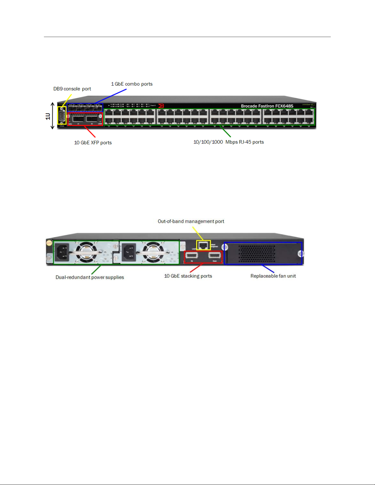
Brocade FastIron CX Series: FCX624S-HPOE
• Compact 1U form factor
• 24 or 48 10/100/1000 Mbps RJ-45 ports, with or without PoE/PoE+
• Four GbE SFP combo ports
• Two optional 10 GbE XFP ports
• DB9 console port for management
• LEDs for port status, stack member ID, and more
• 16 dedicated GbE stacking ports
• Optional second hot-swappable, redundant power supply
• Replaceable fan unit providing side-to-rear airflow
• 10/100/1000 out-of-band management port
RFS6000 Controller
• Mid to large enterprises
• 48 Access Points (APs) per switch
• 256 Adptive Access Points (AAPs) per switch
• 576 APs per cluster
• 3,072 AAPs per cluster
• Expansion slots for 3G/4G wireless backhaul and voice
• 2,000 – 20,000 users
Deploying Brocade Mobility Products with the Brocade FastIron CX Series Page 3 of 16
Page 4
ENTERPRISE & MOBILITY DEPLOYMENT GUIDE
RFS7000 Controller
• Large enterprises and data centers
• 256 Access Points (APs) per switch
• 1,024 AAPs per switch
• 3,072 APs per cluster
• 12,280,072 AAPs per cluster
• 8,000 – 96,000 users
For both controllers, clustering provides:
• Seamless Layer 2/3 mobility between RF switches
• Smart license sharing
• Dynamic AP load balancing
• AP steering
• High Availability (HA) during RF switch/network failure (manual or automatic reversion)
• Increased aggregate throughput/scaling
Centralized configuration is performed via a cluster Command-Line Interface (CLI) and Web interface
State information exchange is provided for:
• AP and MU distribution
• Identify unauthorized APs
• Smart RF
• Integrated DHCP
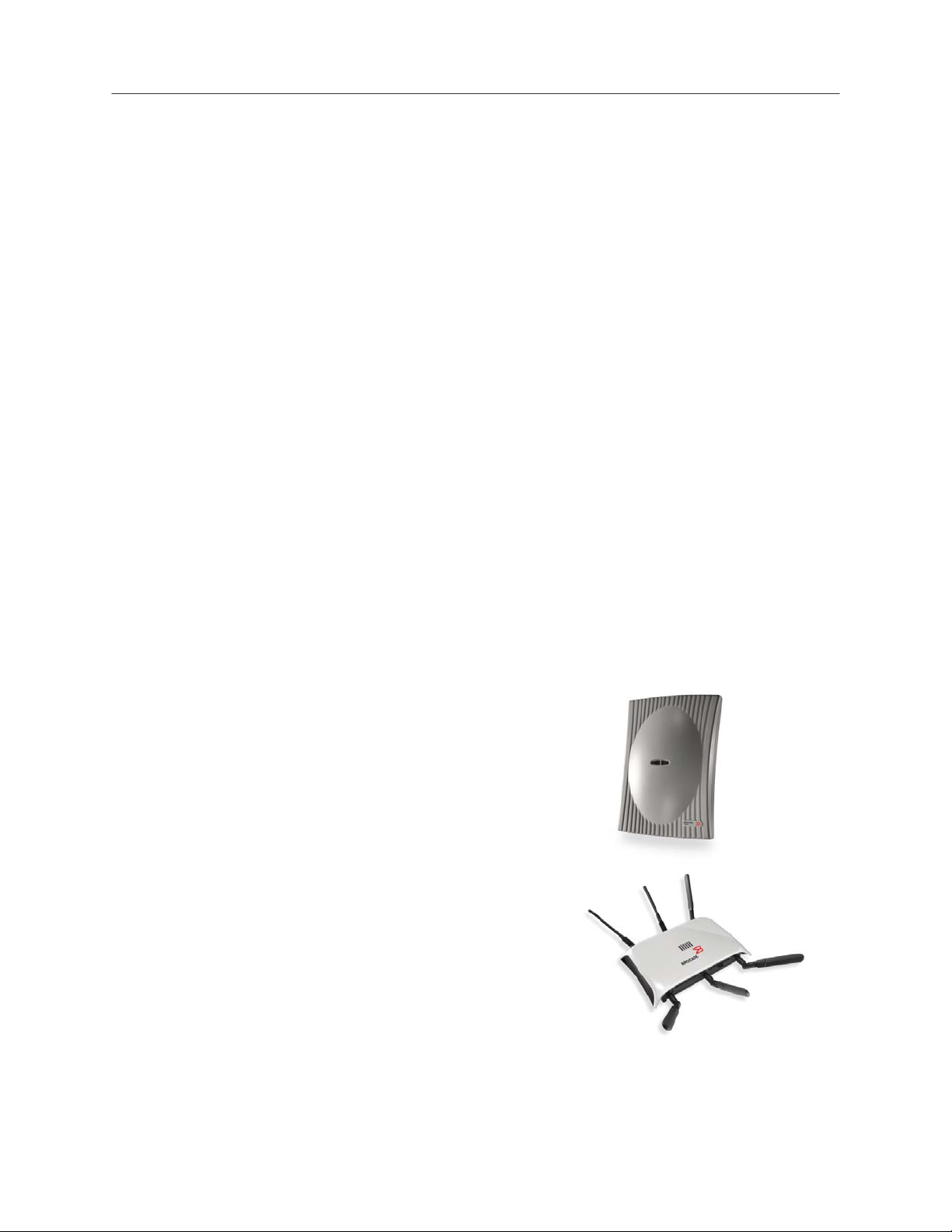
Brocade Mobility AP300
• Thin indoor access point
• Single 802.11b/g or dual-band 802.11a/b/g radios
• External antenna support
• Deployed with a centralized wireless controller
• WIPS sensor mode
Brocade Mobility AP7131
• Full-feature indoor access point
• Dual-band 802.11a/b/g/n radios
• Standalone or distributed with a centralized wireless controller
• Wireless mesh support
• WIPS sensor mode
Deploying Brocade Mobility Products with the Brocade FastIron CX Series Page 4 of 16
Page 5

ENTERPRISE & MOBILITY DEPLOYMENT GUIDE
Corporate Office
Dedicated
sensor
Central
appliance
Field Office
Integrated
AP/Sensor
Network
Brocade Mobility AP5181
• Full-feature, hardened access point
• Designed for harsh environments
• Dual-band 802.11a/b/g radios
• External antenna support
• Standalone or distributed with a centralized wireless controller
• Wireless mesh support
• WIPS sensor mode
Motorola AirDefense
• Centralized, hardened appliance
• Protection for WLAN infrastructure and devices
• Secure Layer 3 connections between sensors and appliance
• Minimal WAN bandwidth needed by sensors: less than 3 Kbps
• Two types of sensors
• All sensors provide 24x7 protection for gap-free security
NOTE: In the illustration, red is used to flag a rogue AP.
- Dedicated sensors are separate devices; use one for
every 3 to 5 APs
- Integrated sensors are built into Brocade Mobility
access points
Deploying Brocade Mobility Products with the Brocade FastIron CX Series Page 5 of 16
Page 6

ENTERPRISE & MOBILITY DEPLOYMENT GUIDE
DESIGN EXAMPLE
ERVER REQUIREMENTS
S
Hardware:
• Windows Server 2003, 2008, or XP
• Intel Dual CPU Core2 duo 2.4GHz or equivalent
• 4 GB memory
• 40 GB disk space
System Services:
• DHCP Server
• Domain Name Server (DNS)
• Microsoft Explorer
• Mozilla Firefox
• Console Port
• Ethernet connectivity
Deploying Brocade Mobility Products with the Brocade FastIron CX Series Page 6 of 16
Page 7

ENTERPRISE & MOBILITY DEPLOYMENT GUIDE
WHAT’S IN THE BOX
Brocade FCX 624S-HPOE
• Brocade FastIron CX device
• 115V AC power cable (for AC sourced devices)
• Rack-mount brackets
• Warranty card
• A straight-through EIA or TIA DB-9 serial cable (F/F).
Brocade RFS7000
• Mobility RFS7000 Controller with rack brackets installed
• Console cable
• Deploying Brocade Mobility Products with the Brocade FastIron CX Series (this document)
• China RoHS compliance document
Brocade AP300 (internal antenna)
• Brocade Mobility 300 antenna
• 2 x screws
• 2 x wall anchors
• Quick Installation Guide (hardware only, no configuration)
Brocade AP7131
• Mobility 7131 model access point (accessories depend on SKU ordered)
• Deploying Brocade Mobility Products with the Brocade FastIron CX Series (this document)
• Wall mount screw and anchor kit
• Accessories Bag (4 x rubber feet, LED light pipe, badge with label for above-the-ceiling installation)
• China RoHS compliance addendum
Brocade AP5181
• Mobility 5181 802.11 a+bg dual-radio access point
• Deploying Brocade Mobility Products with the Brocade FastIron CX Series (this document)
• Set of cable connectors
• 3 x antenna connector dust covers
• 2 x connector cover AP67 jacks, plus chain_LTW-M9/14-SB
• Waste Electrical and Equipment (WEEE) addendum
Deploying Brocade Mobility Products with the Brocade FastIron CX Series Page 7 of 16
Page 8

ENTERPRISE & MOBILITY DEPLOYMENT GUIDE
CONFIGURING WINDOWS SERVICES
Step 1: Set up DNS
1. Go to the Windows Configure Your Server wizard.
2. Enable DNS Server.
3. Create the domain.
4. Add RFS7000 to the forward lookup table.
Step 2: Set up DHCP
1. Go to the Windows Configure Your Server wizard.
2. Enable DHCP Server.
3. Create reservations for RFS7000 and APs.
Step 3: Configure IE for RFS7000 and AP Web servers
1. Open an IE browser window.
2. Go to Tools > Internet Options > Advanced.
3. Deselect Use HTTP 1.1.
CONFIGURING THE BROCADE FCX 624S-HPOE SWITCH
Step 1: Provide power to the switch
Step 2: Connect to the console port interface
1. Connect a PC or terminal to the serial port of the system using a straight-through cable. The serial port has
a male DB-9 connector. NOTE: You need to run a terminal emulation program on the PC.
2. Launch the terminal emulation program and set the following session parameters:
- Baud: 9600 bps
- Data bits: 8
- Parity: None
- Stop bits: 1
- Flow control: None
NOTE: The EIA or TIA 232 serial communication port serves as a connection point for management by a PC
or SNMP workstation. Brocade devices come with a standard male DB-9 connector
Step 3: Basic switch configuration
1. Enter Privileged Mode:
FCX _SW>
FCX _SW#
2. Enter configuration mode:
FCX _SW#conf t
FCX _SW(config)#
Deploying Brocade Mobility Products with the Brocade FastIron CX Series Page 8 of 16
Page 9

ENTERPRISE & MOBILITY DEPLOYMENT GUIDE
3. Configure the basics.
a. Hostname:
CX_SW(config)#hostname RSL_RACK_1_SW
b. Banner:
RSL_RACK_1_SW(config)#banner Wireless Lab
4. Set the management VLAN IP address for Telnet.
a. Set VLAN 1:
RSL_RACK_1_SW(config)#vlan 1
RSL_RACK_1_SW(config-vlan-1)#
b. Enable management VLAN:
RSL_RACK_1_SW(config-vlan-1)#management-vlan
c. Enable telnet on management VLAN1:
RSL_RACK_1_SW(config)#telnet server enable vlan 1
d. Set the Telnet password:
RSL_RACK_1_SW(config)#enable telnet password password
5. Set the default gateway:
RSL_RACK_1_SW(config)#vlan 1
RSL_RACK_1_SW(config-vlan-1)#default-gateway 10.1.1.1 1
Step 4: Configure VLANs
1. Create a wireless VLAN:
RSL_RACK_1_SW(config)#vlan 20
RSL_RACK_1_SW(config-vlan-20)#
2. Tag wireless VLAN ports:
RSL_RACK_1_SW(config-vlan-20)#tagged ethernet 1/1/20
Deploying Brocade Mobility Products with the Brocade FastIron CX Series Page 9 of 16
Page 10

ENTERPRISE & MOBILITY DEPLOYMENT GUIDE
Step 5: Configure Interfaces for POE
1. Enter the interface connected to the AP:
RSL_RACK_1_SW(config)#int eth 1/1/20
RSL_RACK_1_SW(config-if-e1000-1/1/20)#
2. Provide a port name description for what is connected:
RSL_RACK_1_SW(config-if-e1000-1/1/20)#port-name Connected to BR-AP7131
3. Enable the port POE:
RSL_RACK_1_SW(config-if-e1000-1/1/20)#inline power
CONFIGURING THE BROCADE RFS7000 CONTROLLER
Step 1: Provide power to the controller
Step 2: Set up the controller console port
To add the Brocade Mobility RFS7000 Controller to the network and prepare it for initial configuration:
1. Using the console cable provided, connect the Mobility RFS7000 Controller serial port to an RS-232 (DB-9)
serial port on a separate computer (the “configuration computer”).
2. On the configuration computer, configure a terminal emulation application (such as HyperTerminal):
- 19200bps transfer rate
- 8 data bits
- No parity
- 1 stop bit
- No flow control
- No hardware compression
Step 3: Set the IP address for the controller
1. Connect to the RFS7000 console port.
2. Initial login:
- login: cli
- User Access Verification
- Username: admin
- Password: admin123
- Brocade WLAN Controller
- BR-RFS7000>
3. Enter Privileged Mode
BR-RFS7000>enable
BR-RFS7000#
Deploying Brocade Mobility Products with the Brocade FastIron CX Series Page 10 of 16
Page 11

ENTERPRISE & MOBILITY DEPLOYMENT GUIDE
4. Enter Configuration Mode:
BR-RFS7000#conf t
Enter configuration commands, one per line. End with CNTL/Z.
BR-RFS7000(config)#
5. Change the host name:
BR-RFS7000(config)#hostname RSL_BR-RFS7000
RSL_BR-RFS7000(config)#
6. Add the management IP address to VLAN 1:
RSL_BR-RFS7000(config)#int vlan 1
RSL_BR-RFS7000(config-if)#management
- For DHCP (default): RSL_BR-RFS7000(config-if)#ip address dhcp
- For Static IP: ip address 10.1.1.2/24
Step 4: Basic controller configuration
1. Connect to the RFS7000 with HTTP.
a. Open IE Explorer (HTTP 1.1 disabled) with the IP address learned from DHCP or set it statically
(http://10.1.1.2/).
b. Enter a user name (admin) and password (admin123).
Deploying Brocade Mobility Products with the Brocade FastIron CX Series Page 11 of 16
 Loading...