

Brocade Communications Systems FastIron SuperX, FastIron SX 1600, FSX 1600, FastIron SX 1600 Acoustic Noise-Reduced, FSX 1600-ANR Hardware Installation Manual
...
53-1001723-02
®
18 March 10
Brocade FastIron X Series
Chassis
Hardware Installation Guide
Supporting Release 07.0.01b
Copyright © 2010 Brocade Communications Systems, Inc. All Rights Reserved.
Brocade, the B-wing symbol, BigIron, DCX, Fabric OS, FastIron, IronPoint, IronShield, IronView, IronWare, JetCore, NetIron,
SecureIron, ServerIron, StorageX, and TurboIron are registered trademarks, and DCFM, Extraordinary Networks, and SAN Health
are trademarks of Brocade Communications Systems, Inc., in the United States and/or in other countries. All other brands,
products, or service names are or may be trademarks or service marks of, and are used to identify, products or services of their
respective owners.
Notice: This document is for informational purposes only and does not set forth any warranty, expressed or implied, concerning
any equipment, equipment feature, or service offered or to be offered by Brocade. Brocade reserves the right to make changes to
this document at any time, without notice, and assumes no responsibility for its use. This informational document describes
features that may not be currently available. Contact a Brocade sales office for information on feature and product availability.
Export of technical data contained in this document may require an export license from the United States government.
The authors and Brocade Communications Systems, Inc. shall have no liability or responsibility to any person or entity with
respect to any loss, cost, liability, or damages arising from the information contained in this book or the computer programs that
accompany it.
The product described by this document may contain “open source” software covered by the GNU General Public License or other
open source license agreements. To find-out which open source software is included in Brocade products, view the licensing
terms applicable to the open source software, and obtain a copy of the programming source code, please visit
http://www.brocade.com/support/oscd.
Brocade Communications Systems, Incorporated
Corporate and Latin American Headquarters
Brocade Communications Systems, Inc.
1745 Technology Drive
San Jose, CA 95110
Tel: 1-408-333-8000
Fax: 1-408-333-8101
E-mail: info@brocade.com
European Headquarters
Brocade Communications Switzerland Sàrl
Centre Swissair
Tour B - 4ème étage
29, Route de l'Aéroport
Case Postale 105
CH-1215 Genève 15
Switzerland
Tel: +41 22 799 5640
Fax: +41 22 799 5641
E-mail: emea-info@brocade.com
Asia-Pacific Headquarters
Brocade Communications Systems China HK, Ltd.
No. 1 Guanghua Road
Chao Yang District
Units 2718 and 2818
Beijing 100020, China
Tel: +8610 6588 8888
Fax: +8610 6588 9999
E-mail: china-info@brocade.com
Asia-Pacific Headquarters
Brocade Communications Systems Co., Ltd. (Shenzhen WFOE)
Citic Plaza
No. 233 Tian He Road North
Unit 1308 – 13th Floor
Guangzhou, China
Tel: +8620 3891 2000
Fax: +8620 3891 2111
E-mail: china-info@brocade.com
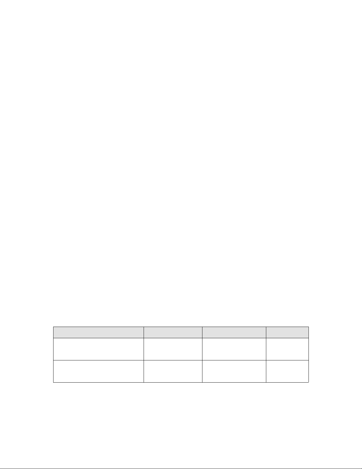
Document History
Title Publication number Summary of changes Date
Brocade FastIron X Series Chassis
Hardware Installation Guide supporting
release 07.0.01b
Brocade FastIron X Series Chassis
Hardware Installation Guide supporting
release 07.0.01a
53-1001723-02 Updated release version Mar 2010
53-1001723-01 New document Feb 2010

Contents
About This Document
Audience . . . . . . . . . . . . . . . . . . . . . . . . . . . . . . . . . . . . . . . . . . . . . . . . ix
Supported hardware and software . . . . . . . . . . . . . . . . . . . . . . . . . . . ix
Document conventions. . . . . . . . . . . . . . . . . . . . . . . . . . . . . . . . . . . . . ix
Text formatting . . . . . . . . . . . . . . . . . . . . . . . . . . . . . . . . . . . . . . . . x
Command syntax conventions . . . . . . . . . . . . . . . . . . . . . . . . . . . x
Notes, cautions, and danger notices . . . . . . . . . . . . . . . . . . . . . . x
Notice to the reader . . . . . . . . . . . . . . . . . . . . . . . . . . . . . . . . . . . . . . . xi
Related publications . . . . . . . . . . . . . . . . . . . . . . . . . . . . . . . . . . . . . . . xi
Getting technical help or reporting errors . . . . . . . . . . . . . . . . . . . . . . xi
Web access . . . . . . . . . . . . . . . . . . . . . . . . . . . . . . . . . . . . . . . . . xii
E-mail access . . . . . . . . . . . . . . . . . . . . . . . . . . . . . . . . . . . . . . . . xii
Telephone access . . . . . . . . . . . . . . . . . . . . . . . . . . . . . . . . . . . . xii
Chapter 1 Product Overview
Product overview. . . . . . . . . . . . . . . . . . . . . . . . . . . . . . . . . . . . . . . . . .1
Hardware benefits . . . . . . . . . . . . . . . . . . . . . . . . . . . . . . . . . . . . . 1
POE port density. . . . . . . . . . . . . . . . . . . . . . . . . . . . . . . . . . . . . . . 2
Supported configurations . . . . . . . . . . . . . . . . . . . . . . . . . . . . . . .2
Software features . . . . . . . . . . . . . . . . . . . . . . . . . . . . . . . . . . . . . . . . . 3
POE applications . . . . . . . . . . . . . . . . . . . . . . . . . . . . . . . . . . . . . . . . . . 3
Support for IPv6 modules. . . . . . . . . . . . . . . . . . . . . . . . . . . . . . . . . . . 3
IPv6 hardware support guidelines . . . . . . . . . . . . . . . . . . . . . . . .3
Hardware features . . . . . . . . . . . . . . . . . . . . . . . . . . . . . . . . . . . . . . . . 4
FSX chassis . . . . . . . . . . . . . . . . . . . . . . . . . . . . . . . . . . . . . . . . . . 4
FSX 800 chassis . . . . . . . . . . . . . . . . . . . . . . . . . . . . . . . . . . . . . . 7
FSX 1600 chassis . . . . . . . . . . . . . . . . . . . . . . . . . . . . . . . . . . . . . 9
FSX 1600-ANR chassis . . . . . . . . . . . . . . . . . . . . . . . . . . . . . . . . 12
Management modules . . . . . . . . . . . . . . . . . . . . . . . . . . . . . . . .14
Switch fabric modules (FSX 800 and FSX 1600 only) . . . . . . .22
Interface modules . . . . . . . . . . . . . . . . . . . . . . . . . . . . . . . . . . . .23
Network interfaces. . . . . . . . . . . . . . . . . . . . . . . . . . . . . . . . . . . .30
Power supplies. . . . . . . . . . . . . . . . . . . . . . . . . . . . . . . . . . . . . . . 31
Cooling system. . . . . . . . . . . . . . . . . . . . . . . . . . . . . . . . . . . . . . .38
Built-in mounting brackets . . . . . . . . . . . . . . . . . . . . . . . . . . . . .39
Layer 3 routing protocol table sizes. . . . . . . . . . . . . . . . . . . . . . . . . .39
Brocade FastIron X Series Chassis Hardware Installation Guide iii
53-1001723-02

Chapter 2 Installing the Chassis
Overview . . . . . . . . . . . . . . . . . . . . . . . . . . . . . . . . . . . . . . . . . . . . . . . 41
Summary of installation tasks . . . . . . . . . . . . . . . . . . . . . . . . . . . . . . 41
Unpacking a system . . . . . . . . . . . . . . . . . . . . . . . . . . . . . . . . . . . . . .42
Installation precautions . . . . . . . . . . . . . . . . . . . . . . . . . . . . . . . . . . .43
General precautions . . . . . . . . . . . . . . . . . . . . . . . . . . . . . . . . . .43
Lifting precautions . . . . . . . . . . . . . . . . . . . . . . . . . . . . . . . . . . . .44
Power precautions and warnings . . . . . . . . . . . . . . . . . . . . . . . .44
Preparing the installation site . . . . . . . . . . . . . . . . . . . . . . . . . . . . . . 47
Cabling infrastructure . . . . . . . . . . . . . . . . . . . . . . . . . . . . . . . . . 47
Installation location . . . . . . . . . . . . . . . . . . . . . . . . . . . . . . . . . . . 47
Removing extra shipment screws (FSX and FSX 800 only) . . . . . . . 47
Installing a chassis in a rack . . . . . . . . . . . . . . . . . . . . . . . . . . . . . . .48
Installing mounting brackets on the FSX 1600 chassis . . . . . .50
Removing the slot panels . . . . . . . . . . . . . . . . . . . . . . . . . . . . . . . . . . 50
Installing the management and interface modules . . . . . . . . . . . . .51
Attaching a management station. . . . . . . . . . . . . . . . . . . . . . . . . . . . 56
Attaching a PC or terminal to the console port or 10/100/1000
copper port. . . . . . . . . . . . . . . . . . . . . . . . . . . . . . . . . . . . . . . . . . 57
Attaching a switch to an Ethernet port. . . . . . . . . . . . . . . . . . . .57
Powering on the system . . . . . . . . . . . . . . . . . . . . . . . . . . . . . . . . . . .58
Connecting AC power to the chassis. . . . . . . . . . . . . . . . . . . . . .58
Connecting DC power to the chassis . . . . . . . . . . . . . . . . . . . . .60
Verifying proper operation . . . . . . . . . . . . . . . . . . . . . . . . . . . . . . . . . 63
Observing the LEDs . . . . . . . . . . . . . . . . . . . . . . . . . . . . . . . . . . .64
Displaying the module status . . . . . . . . . . . . . . . . . . . . . . . . . . .66
Chapter 3 Connecting Network Devices and Checking Connectivity
Overview . . . . . . . . . . . . . . . . . . . . . . . . . . . . . . . . . . . . . . . . . . . . . . .69
Assigning permanent passwords . . . . . . . . . . . . . . . . . . . . . . . . . . . .69
Recovering from a lost password . . . . . . . . . . . . . . . . . . . . . . . .70
Configuring IP addresses . . . . . . . . . . . . . . . . . . . . . . . . . . . . . . . . . . 71
IPv4 devices . . . . . . . . . . . . . . . . . . . . . . . . . . . . . . . . . . . . . . . . . 71
IPv6 devices . . . . . . . . . . . . . . . . . . . . . . . . . . . . . . . . . . . . . . . . .73
Connecting network devices. . . . . . . . . . . . . . . . . . . . . . . . . . . . . . . . 76
Cable specifications. . . . . . . . . . . . . . . . . . . . . . . . . . . . . . . . . . . 76
Connecting to Ethernet or fast Ethernet hubs . . . . . . . . . . . . . .76
Connecting to workstations, servers, or routers . . . . . . . . . . . .78
Connecting a network device to a fiber port on the Brocade device
78
Automatic MDI or MDIX detection. . . . . . . . . . . . . . . . . . . . . . . .80
Using a CX4 transceiver. . . . . . . . . . . . . . . . . . . . . . . . . . . . . . . .80
Testing network connectivity . . . . . . . . . . . . . . . . . . . . . . . . . . . . . . . 81
Observing LEDs . . . . . . . . . . . . . . . . . . . . . . . . . . . . . . . . . . . . . . 81
iv Brocade FastIron X Series Chassis Hardware Installation Guide
53-1001723-02

Troubleshooting network connections. . . . . . . . . . . . . . . . . . . . . . . .82
Support for digital optical monitoring. . . . . . . . . . . . . . . . . . . . .83
Chapter 4 Managing the Chassis and Modules
Overview . . . . . . . . . . . . . . . . . . . . . . . . . . . . . . . . . . . . . . . . . . . . . . .85
Displaying chassis status and temperature readings . . . . . . . . . . .85
Managing the cooling system. . . . . . . . . . . . . . . . . . . . . . . . . . . . . . .90
Configuring the cooling system. . . . . . . . . . . . . . . . . . . . . . . . . .90
Monitoring the cooling system . . . . . . . . . . . . . . . . . . . . . . . . . .96
Displaying the Syslog configuration and static and dynamic buffers98
Syslog messages for PCI (hardware) errors. . . . . . . . . . . . . . . . . . . .99
Managing the switch fabric modules (FSX 800 and FSX 1600 only)99
Displaying management module CPU usage . . . . . . . . . . . . . . . . .100
Removing MAC address entries . . . . . . . . . . . . . . . . . . . . . . . . . . . .101
Chapter 5 Using a Redundant Management Module
Overview . . . . . . . . . . . . . . . . . . . . . . . . . . . . . . . . . . . . . . . . . . . . . .103
How Management module redundancy works . . . . . . . . . . . . . . . .103
Management module redundancy overview . . . . . . . . . . . . . .103
Management module switchover . . . . . . . . . . . . . . . . . . . . . . .104
Switchover implications. . . . . . . . . . . . . . . . . . . . . . . . . . . . . . .105
Management module redundancy configuration . . . . . . . . . . . . . .106
Changing the default active chassis slot . . . . . . . . . . . . . . . . .106
Managing management module redundancy. . . . . . . . . . . . . . . . .107
File synchronization between the active and standby management
modules . . . . . . . . . . . . . . . . . . . . . . . . . . . . . . . . . . . . . . . . . . .107
Manually switching over to the standby management module108
Rebooting the active and standby management modules . . .109
Hitless management support. . . . . . . . . . . . . . . . . . . . . . . . . . . . . .109
What happens during a Hitless OS upgrade and Hitless switchover
110
How a Hitless OS upgrade and Hitless switchover impacts system
functions. . . . . . . . . . . . . . . . . . . . . . . . . . . . . . . . . . . . . . . . . . .110
Syslog message for Hitless OS upgrade and Hitless switchover111
Layer 2 Hitless switchover. . . . . . . . . . . . . . . . . . . . . . . . . . . . .111
Monitoring management module redundancy . . . . . . . . . . . . . . . .114
Determining management module status . . . . . . . . . . . . . . . .114
Displaying temperature information . . . . . . . . . . . . . . . . . . . . .115
Displaying switchover information . . . . . . . . . . . . . . . . . . . . . .116
Chapter 6 Maintaining the Hardware
Overview . . . . . . . . . . . . . . . . . . . . . . . . . . . . . . . . . . . . . . . . . . . . . .117
Hardware maintenance schedule . . . . . . . . . . . . . . . . . . . . . . . . . .117
Cleaning the fiber optic connectors. . . . . . . . . . . . . . . . . . . . . . . . .117
Brocade FastIron X Series Chassis Hardware Installation Guide v
53-1001723-02

Replacing a management module. . . . . . . . . . . . . . . . . . . . . . . . . .118
Installation precautions. . . . . . . . . . . . . . . . . . . . . . . . . . . . . . .118
Removing a management module . . . . . . . . . . . . . . . . . . . . . .118
Installing a new management module. . . . . . . . . . . . . . . . . . .119
Replacing a switch fabric module (FSX 800 and FSX 1600 only) .121
Removing a switch fabric module. . . . . . . . . . . . . . . . . . . . . . .122
Installing a new switch fabric module . . . . . . . . . . . . . . . . . . .122
Replacing an interface module . . . . . . . . . . . . . . . . . . . . . . . . . . . .124
Precautions . . . . . . . . . . . . . . . . . . . . . . . . . . . . . . . . . . . . . . . .125
Before removing an interface module . . . . . . . . . . . . . . . . . . .125
Removing an interface module . . . . . . . . . . . . . . . . . . . . . . . . .126
Installing a new interface module. . . . . . . . . . . . . . . . . . . . . . .126
Configuring a LAN or WAN Phy interface module . . . . . . . . . .129
Disabling and re-enabling an interface module. . . . . . . . . . . .130
Installing or replacing a POE daughter card . . . . . . . . . . . . . . . . . .131
Replacing a copper or fiber optic module . . . . . . . . . . . . . . . . . . . .134
Removing a copper or fiber optic module . . . . . . . . . . . . . . . .134
Installing a new copper or fiber optic module . . . . . . . . . . . . .135
Cabling a fiber optic module . . . . . . . . . . . . . . . . . . . . . . . . . . .135
Installing or replacing a power supply . . . . . . . . . . . . . . . . . . . . . . .136
Determining which power supply failed . . . . . . . . . . . . . . . . . .136
Removing an AC power supply . . . . . . . . . . . . . . . . . . . . . . . . .137
Removing a DC power supply . . . . . . . . . . . . . . . . . . . . . . . . . .139
Installing a new power supply. . . . . . . . . . . . . . . . . . . . . . . . . .141
Connecting AC power to the chassis. . . . . . . . . . . . . . . . . . . . .145
Connecting DC power to the chassis . . . . . . . . . . . . . . . . . . . . 147
Verifying proper operation . . . . . . . . . . . . . . . . . . . . . . . . . . . . .149
Displaying the status of the power supplies . . . . . . . . . . . . . .151
Replacing the FSX and FSX 800 fan tray. . . . . . . . . . . . . . . . . . . . .151
Replacing the FSX 1600 fan assemblies . . . . . . . . . . . . . . . . . . . .154
Replacing the FSX 1600-ANR fan assemblies . . . . . . . . . . . . . . . .155
Replacing the air filter in the FastIron SX-1600 . . . . . . . . . . . . . . .157
Upgrading the device to run Layer 3 software . . . . . . . . . . . . . . . .158
Chapter 7 Hardware Specifications
Overview . . . . . . . . . . . . . . . . . . . . . . . . . . . . . . . . . . . . . . . . . . . . . .159
Chassis specifications . . . . . . . . . . . . . . . . . . . . . . . . . . . . . . . . . . .159
Physical dimensions . . . . . . . . . . . . . . . . . . . . . . . . . . . . . . . . .159
Environmental considerations . . . . . . . . . . . . . . . . . . . . . . . . .159
Cooling . . . . . . . . . . . . . . . . . . . . . . . . . . . . . . . . . . . . . . . . . . . .160
Regulatory compliance . . . . . . . . . . . . . . . . . . . . . . . . . . . . . . .163
Maximum power consumption . . . . . . . . . . . . . . . . . . . . . . . . .164
Power source interruptions . . . . . . . . . . . . . . . . . . . . . . . . . . . .165
Pinouts and signalling . . . . . . . . . . . . . . . . . . . . . . . . . . . . . . . .165
Cable specifications. . . . . . . . . . . . . . . . . . . . . . . . . . . . . . . . . .168
Power cords . . . . . . . . . . . . . . . . . . . . . . . . . . . . . . . . . . . . . . . .169
vi Brocade FastIron X Series Chassis Hardware Installation Guide
53-1001723-02

Power supply specifications . . . . . . . . . . . . . . . . . . . . . . . . . . . . . . .170
Physical dimensions and weight. . . . . . . . . . . . . . . . . . . . . . . .170
Environmental considerations . . . . . . . . . . . . . . . . . . . . . . . . .170
Electrical specifications. . . . . . . . . . . . . . . . . . . . . . . . . . . . . . .171
Input connector and plug . . . . . . . . . . . . . . . . . . . . . . . . . . . . .172
Regulatory compliance . . . . . . . . . . . . . . . . . . . . . . . . . . . . . . .174
Safety warnings . . . . . . . . . . . . . . . . . . . . . . . . . . . . . . . . . . . . . 174
Appendix A Layer 3 Upgrade Procedures
Overview . . . . . . . . . . . . . . . . . . . . . . . . . . . . . . . . . . . . . . . . . . . . . .175
Upgrade kit contents. . . . . . . . . . . . . . . . . . . . . . . . . . . . . . . . . . . . .175
Installation overview . . . . . . . . . . . . . . . . . . . . . . . . . . . . . . . . . . . . .183
Detailed procedure . . . . . . . . . . . . . . . . . . . . . . . . . . . . . . . . . . . . . .184
Hardware installation. . . . . . . . . . . . . . . . . . . . . . . . . . . . . . . . .184
Software installation . . . . . . . . . . . . . . . . . . . . . . . . . . . . . . . . .186
Appendix B Regulatory Statements
U.S.A. . . . . . . . . . . . . . . . . . . . . . . . . . . . . . . . . . . . . . . . . . . . . . . . . .189
Industry Canada statement . . . . . . . . . . . . . . . . . . . . . . . . . . . . . . .189
Europe and Australia. . . . . . . . . . . . . . . . . . . . . . . . . . . . . . . . . . . . .189
Japan VCCI statement. . . . . . . . . . . . . . . . . . . . . . . . . . . . . . . . . . . .189
Japan Denan power cord statement . . . . . . . . . . . . . . . . . . . . . . . .190
Korea . . . . . . . . . . . . . . . . . . . . . . . . . . . . . . . . . . . . . . . . . . . . . . . . .190
Russia . . . . . . . . . . . . . . . . . . . . . . . . . . . . . . . . . . . . . . . . . . . . . . . .190
Appendix C Caution and Danger Notices
Cautions. . . . . . . . . . . . . . . . . . . . . . . . . . . . . . . . . . . . . . . . . . . . . . .193
Dangers . . . . . . . . . . . . . . . . . . . . . . . . . . . . . . . . . . . . . . . . . . . . . . .200
Brocade FastIron X Series Chassis Hardware Installation Guide vii
53-1001723-02

viii Brocade FastIron X Series Chassis Hardware Installation Guide
53-1001723-02

About This Document
NOTE
Audience
This document is designed for system administrators with a working knowledge of Layer 2 and
Layer 3 switching and routing.
If you are using a Brocade Layer 3 Switch, you should be familiar with the following protocols if
applicable to your network – IP, RIP, OSPF, BGP, IGMP, PIM, DVMRP, and VRRP.
Supported hardware and software
The following hardware platforms are supported by this release of this guide:
• FastIron SuperX® (FSX)
• FastIron SX 800® (FSX 800)
• FastIron SX 1600® (FSX 1600)
• FastIron SX 1600-ANR® (FSX 1600-ANR) Layer 2 or Layer 3 switches
This document describes software release 07.0.01b only. Refer to earlier releases of this guide for
information about software releases prior to 07.0.01b.
Document conventions
This section describes text formatting conventions and important notice formats used in this
document.
Brocade FastIron X Series Chassis Hardware Installation Guide ix
53-1001723-02

Text formatting
NOTE
The following narrative-text formatting conventions are used in this guide.
bold text Identifies command names
Identifies the names of user-manipulated GUI elements
Identifies keywords
Identifies text to enter at the GUI or CLI
italic text Provides emphasis
Identifies variables
Identifies document titles
code text Identifies CLI output
For readability, command names in the narrative portions of this guide are presented in bold: for
example, show version.
Command syntax conventions
The following conventions for command syntax are used in this guide.
command and
parameters
[ ] Optional parameter.
variable Variables are printed in italics enclosed in angled brackets < >.
... Repeat the previous element, for example “member[;member...]”
| Choose from one of the parameters.
Commands and parameters are printed in bold.
Notes, cautions, and danger notices
The following notices and statements are used in this manual. They are listed below in order of
increasing severity of potential hazards.
A note provides a tip, guidance or advice, emphasizes important information, or provides a reference
to related information.
x Brocade FastIron X Series Chassis Hardware Installation Guide
53-1001723-02
CAUTION
A Caution statement alerts you to situations that can be potentially hazardous to you or cause
DANGER
NOTE
damage to hardware, firmware, software, or data.
A Danger statement indicates conditions or situations that can be potentially lethal or extremely
hazardous to you. Safety labels are also attached directly to products to warn of these conditions
or situations.
Notice to the reader
This document may contain references to the trademarks of the following corporations. These
trademarks are the properties of their respective companies and corporations.
These references are made for informational purposes only.
Corporation Referenced Trademarks and Products
Phillips Screw Company Inc. Phillips
Related publications
The following Brocade documents supplement the information in this guide.
• FastIron Configuration Guide
• Brocade FastIron Compact Switch Hardware Installation Guide
• IronWare MIB Reference
For the latest edition of this document, which contains the most up-to-date information, refer to
Product Manuals at kp.foundrynet.com.
Getting technical help or reporting errors
Brocade is committed to ensuring that your investment in our products remains cost-effective. If
you need assistance, or find errors in the manuals, contact Brocade using one of the following
options.
Brocade FastIron X Series Chassis Hardware Installation Guide xi
53-1001723-02

Web access
Go to myBrocade.com, click the Product Documentation tab, then click on the link to the
Knowledge Portal (KP) to obtain more information about a product, or to report documentation
errors. To report errors, click on Cases > Create a New Ticket in the KP. Make sure you specify the
document title in the ticket description.
E-mail access
Send an e-mail to IPsupport@brocade.com
Telephone access
United States and Canada: 800-752-8061
International: +800-AT FIBREE (+800 28 34 27 33)
Refer to the Services & Support page on www.brocade.com for additional toll-free numbers that
may be available within your country.
Areas unable to access 800 numbers: +1-408-333-6061
xii Brocade FastIron X Series Chassis Hardware Installation Guide
53-1001723-02

Chapter
NOTE
Product Overview
Product overview
This chapter contains an overview of the following FastIron X Series® Layer 2 or Layer 3 switches:
• FastIron SuperX (FSX)
• FastIron SX 800 (FSX 800)
• FastIron SX 1600 (FSX 1600)
• FastIron SX 1600 Acoustic Noise-Reduced (FSX 1600-ANR)
Except for the ANR kit and fan modules in the FSX 1600-ANR chassis, the FSX 1600 and FSX
1600-ANR are similar devices and use the same switch fabric, management and interface modules,
and power supplies. Therefore, the FSX 1600 and FSX 1600-ANR are collectively referred to as the
FSX 1600 chassis throughout this manual, except where explicitly noted.
Designed for medium to large enterprise backbones, the FastIron X Series chassis devices are
modular switches that provide the enterprise network with a complete end-to-end Enterprise LAN
solution, ranging from the wiring closet to the LAN backbone.
1
Hardware benefits
The FastIron X Series chassis devices provide the following benefits:
• The FSX management module is non-blocking, with a built-in switch fabric module and twelve
combination Gigabit Ethernet (GbE) copper or fiber ports that provide connectivity to your
existing management network.
• The FSX 800 and FSX 1600 management modules have a console port and a 10/100/1000
port that provide connectivity to your existing management network. The management
modules optionally support 2-port 10-GbE ports or 8-port GbE fiber and copper ports.
• The FSX 800 and FSX 1600 management modules are interchangeable between devices.
However, you cannot mix IPv4 and IPv6 modules together in the same chassis.
• Optional dual management modules on the FSX 800 and FSX 1600 provide 100% redundancy.
• The crossbar (xbar) architecture enables the management module to switch 30 Gigabits per
second between each interface module and within the management module.
• The interface modules and power supplies are interchangeable among all FastIron X Series
chassis devices. However, you cannot mix IPv4 and IPv6 modules together in the same
chassis.
• The FSX 800 and FSX 1600 management, switch fabric, and interface modules are hot
swappable, which means you can remove and replace them while the chassis is powered on
and running.
• All FastIron X Series chassis devices have a passive backplane.
Brocade FastIron X Series Chassis Hardware Installation Guide 1
53-1001723-02

Product overview
1
• Completely separate data and control planes, which results in uncompromised switching
performance, increased reliability of both planes, and increased security of the control plane in
the event of a Denial of Service (DoS) attack on the data plane.
• Distributed data and control planes, which results in uncompromised wire-speed performance
for the data plane and faster and more efficient performance of management functions for the
control plane.
POE port density
Tab le 1 shows the maximum POE port density for the FastIron X Series chassis devices.
TABLE 1 Maximum number of POE class 3 (15.4W) ports per power supply
Power Supply Number of Power
Supplies
FSX FSX 800 FSX 1600
SX-ACPWR-POE and
SX-DCPWR-POE
SX-ACPWR-POE and
SX-DCPWR-POE
SX-ACPWR-POE and
SX-DCPWR-POE
SX-ACPWR-POE and
SX-DCPWR-POE
SX-ACPWR2500-POE 1 140 140 140
SX-ACPWR2500-POE 2 280
SX-ACPWR2500-POE 3 N/A N/A 420
SX-ACPWR2500-POE 4 N/A N/A 560
1. The FSX and FSX 800 support a maximum of 192 POE ports. The FSX 1600 supports a maximum of 384 POE
ports.
1707070
2 140 140 140
3 N/A N/A 210
4 N/A N/A 280
1
280
1
280
1
1
Supported configurations
Premium FastIron X Series chassis devices support Layer 2 switching and full Layer 3 multiprotocol
routing. Standard devices support Layer 2 and base Layer 3 switching. All standard FastIron X
Series chassis devices can be upgraded to full Layer 3 multiprotocol routing, at which time they are
considered to be premium devices.
Depending on the type of management module installed in the device, IPv6 premium devices
support either IPv4 multiprotocol routing and IPv6 host and management features, or IPv6 and
IPv4 multiprotocol routing and IPv6 host and management features. For more information, refer to
“FSX management modules” on page 14 and “FSX 800 and FSX 1600 management modules” on
page 18.
All FastIron X Series chassis devices optionally support Power over Ethernet (POE), providing the
means for integrating data, voice, and video over existing Ethernet cables.
Tab le 3 lists the configurations supported on the FastIron X Series chassis devices.
2 Brocade FastIron X Series Chassis Hardware Installation Guide
53-1001723-02

TABLE 3 FastIron product family support configurations
Device Standard Premium (PREM) Power over Ethernet
FSX Yes Yes Yes
FSX 800 Yes Yes Yes
FSX 1600 Yes Yes Yes
Software features
Software features differ depending on the software version that is loaded on the device and the
type of management module that is installed in the chassis. Refer to the FastIron Configuration
Guide for a complete list of software features supported on your device.
POE applications
Brocade’s FastIron X Series chassis devices with POE provide Power over Ethernet, compliant with
the standards described in the IEEE 802.3af specification for delivering in-line power. The 802.3af
specification defines the standard for delivering power over existing network cabling infrastructure,
enabling multicast-enabled full streaming audio and video applications for converged services,
such as, Voice over IP (VoIP), WLAN access points, IP surveillance cameras, and other IP technology
devices.
Software features
(POE)
1
POE technology eliminates the need for an electrical outlet and dedicated UPS near IP powered
devices. With power sourcing devices, such as Brocade’s FastIron X Series chassis devices with
POE, power is consolidated and centralized in the wiring closets, improving the reliability and
resiliency of the network. Because POE can provide power over Ethernet cable, power is
continuous, even in the event of a power failure.
For POE port density, refer to “POE port density” on page 2.
For more information about POE and how to configure it, refer to the FastIron Configuration Guide.
Support for IPv6 modules
The FastIron X Series chassis devices support IPv6 management and interface modules.
For details about IPv6 modules, refer to the following sections in this chapter:
• “IPv6 hardware support guidelines”
• “FSX management modules” on page 14
• “FSX 800 and FSX 1600 management modules” on page 18
• “Interface modules” on page 23
IPv6 hardware support guidelines
Note the following guidelines and restrictions with IPv6 Management and Interface modules:
Brocade FastIron X Series Chassis Hardware Installation Guide 3
53-1001723-02

Hardware features
1
• You cannot mix IPv4 and IPv6 modules together in the same FastIron chassis.
• If you install dual IPv6 management modules, the modules must be identical. For example, you
cannot install one 2-port management module and one 8-port management module together
in the same chassis. The modules must be of like-kind.
Hardware features
The FastIron X Series chassis devices are composed of the following major hardware components:
• Chassis
• Management module
• The FSX management module has a built-in switch fabric module.
• The FSX 800 and FSX 1600 optionally support dual management modules which provide
• Separate switch fabric modules (FSX 800 and FSX 1600 only)
• Interface modules
• Power supplies
• The fan tray in the FSX and FSX 800 is composed of six fans and a fan control module.
• The FSX 1600 has an air filter in the bottom front of the chassis and two fan trays at the rear of
the chassis.
• Built-in mounting brackets
The following sections provide more information about these components.
100% redundancy.
For details about physical dimensions, power supply specifications, and pinouts, refer to Chapter 7,
“Hardware Specifications”.
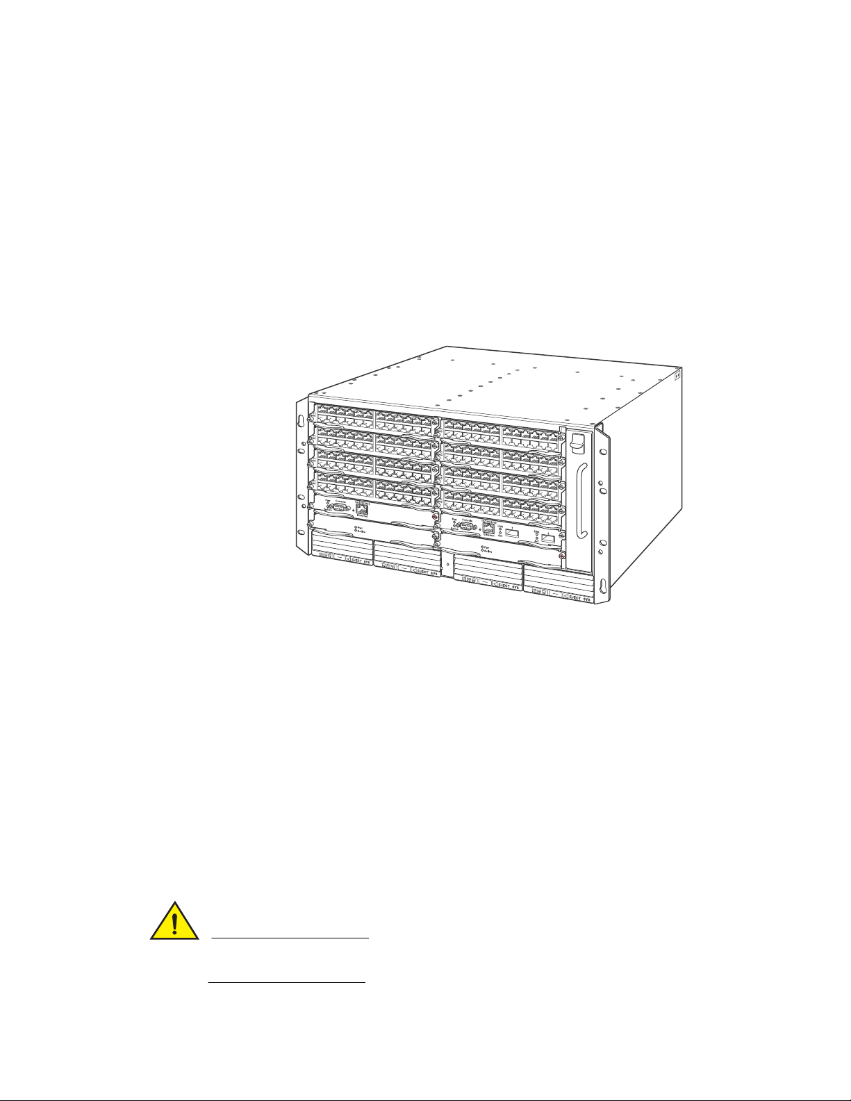
FSX chassis
The FSX chassis is 6 rack units (RUs) in height and consists of the following:
• One full slot for the management module
• Eight half slots for the interface modules
• Four slots for power supplies along the bottom of the card shelf. The power supply slots add an
additional RU to the height of the chassis.
4 Brocade FastIron X Series Chassis Hardware Installation Guide
53-1001723-02
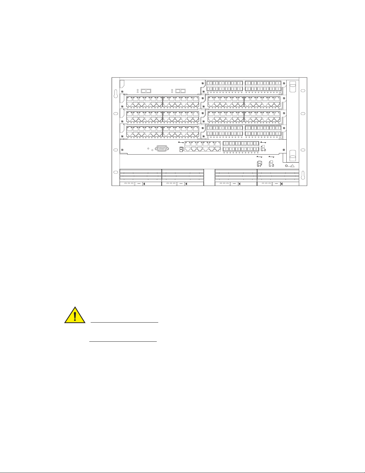
Figure 1 shows the FSX chassis.
CAUTION
DC OK ALMAC OK DC OK ALMAC OK DC OK ALMAC OK DC OK ALMAC OK
8X-12GM-4
Console
Pwr
Lnk
Odd
Even
Odd
Even
Lnk
424F
424C
42XG
424C
424C424C
424F
424C
Odd
Even
Lnk
Lnk
Odd
Even
POE
424C
424F
SYSEJECTSYSEJECTSYSEJECTSYSEJECT
Lnk
Act
Lnk
Act
12
FastIron SuperX
FIGURE 1 FSX chassis
Hardware features
1
Upon shipment from the factory, the following components are installed in the FSX chassis:
• A slot panel in each interface module slot and power supply slot that does not currently have a
module or power supply installed in it. The slot panel ensures proper airflow within the chassis.
• One or two AC or DC power supplies
• A fan tray assembly which contains the cooling system for the chassis
In the FSX slots, you can install the following:
• One management module
• Up to eight interface modules
• Up to four AC and DC power supplies: two system (12-volt) power supplies and two POE (48- or
220-volt) power supplies
Before installing any modules or power supplies, you must remove the slot panel.
If you do not install a module in a slot, you must keep the slot panel in place. If you run the
chassis with an uncovered slot, the system will overheat.
Brocade FastIron X Series Chassis Hardware Installation Guide 5
53-1001723-02
Hardware features
DANGER
DC OK ALMAC OK
SYSEJECT
Odd
Even
Lnk
Lnk
Odd
Even
POE
424C
424F
8X-12GM-4
Console
Pwr
Lnk
Odd
Even
Odd
Even
Lnk
7
5
3
1 2 11
4
6
8
9
10
FastIron SuperX
1
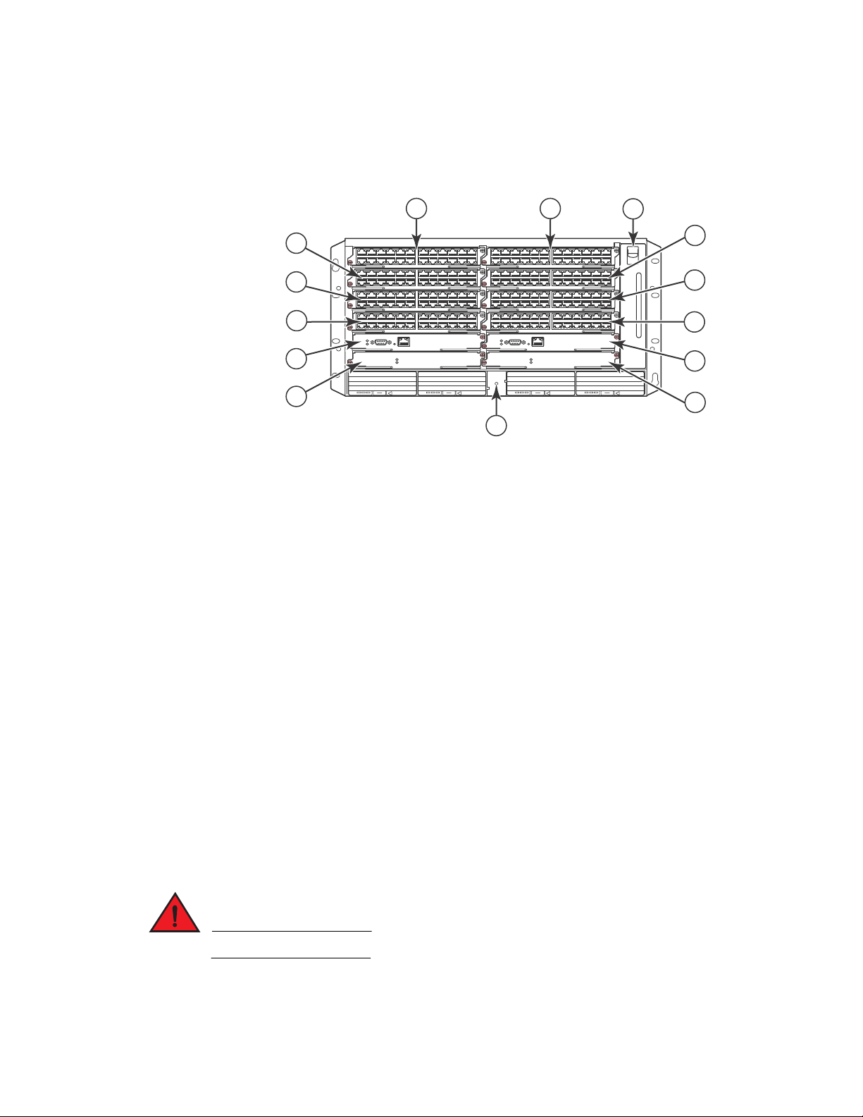
Figure 2 shows the FSX chassis and the slots into which you can install the various modules and
power supplies.
FIGURE 2 FSX chassis slots
1Slot 1
2Slot 2
3Slot 3
4Slot 4
5Slot 5
6Slot 6
7Slot 7
8Slot 8
9Slot 9
10 ESD connector
11 Fan tray
Figure 2 also shows an electrostatic discharge (ESD) connector, into which you can plug an ESD
wrist strap to ground yourself while handling and installing modules.
For safety reasons, the ESD wrist strap should contain a series 1 meg ohm resistor.
6 Brocade FastIron X Series Chassis Hardware Installation Guide
53-1001723-02
Hardware features
CAUTION
1
FSX 800 chassis
The FSX 800 chassis is 6 rack units in height and consists of the following:
• Two half slots for the management modules
• Two half slots for the switch fabric modules
• Eight half slots for the interface modules
• Four slots for power supplies along the bottom of the card shelf. The power supply slots add an
additional rack unit (RU) to the height of the chassis.
Figure 3 shows the FSX 800 chassis.
FIGURE 3 FSX 800 chassis
The FSX 800 chassis ships from the factory with the following components installed:
• Two switch fabric modules
• A slot panel in each interface module slot and power supply slot that does not currently have a
module or power supply installed in it. The slot panel ensures proper airflow within the chassis.
• One AC power supply
• A fan tray assembly which contains the cooling system for the chassis
In the FSX 800 slots, you can install the following:
• Up to two management modules
• Up to 8 interface modules
• Up to four AC and DC power supplies: two system (12-volt) power supplies and two POE (48- or
220-volt) power supplies
Before installing any modules or power supplies, you must remove the slot panel.
If you do not install a module in a slot, you must keep the slot panel in place. If you run the
chassis with an uncovered slot, the system will overheat.
Brocade FastIron X Series Chassis Hardware Installation Guide 7
53-1001723-02
Hardware features
DANGER
1
Figure 4 shows the FSX 800 Chassis and the slots into which you can install the various modules
and power supplies.
FIGURE 4 FSX 800 chassis slots
3
5
7
9
11
1Slot 1
2Slot 2
3Slot 3
4Slot 4
5Slot 5
6Slot 6
7Slot 7
8Slot 8
9Slot 9
10 Slot 10
11 Switch Fabric Slot 1
12 Switch Fabric Slot 2
13 Fan tray
14 ESD connector
1
2
13
4
EJECT POE
F1
424C
F1
424C
F1
424C
F1
424C
10/100/1000
Console
Pwr
Active
Ethernet
Pwr
Active
AC OKDC OKALM
EJECT SYS
AC OKDC OKALM
EJECT SYS
6
8
10
F1
424C
F1
424C
F1
424C
F1
424C
AC OKDC OKALM
10/100/1000
Console
Pwr
Active
Ethernet
Pwr
Active
EJECT POE
AC OKDC OKALM
12
14
Figure 4 also shows an electrostatic discharge (ESD) connector, into which you can plug an ESD
wrist strap to ground yourself while handling and installing modules.
For safety reasons, the ESD wrist strap should contain a series 1 meg ohm resistor.
8 Brocade FastIron X Series Chassis Hardware Installation Guide
53-1001723-02

Hardware features
NOTE
1
FSX 1600 chassis
There are two versions of the FSX 1600 chassis:
• FSX 1600 – Part numbers for chassis and bundles begin with FI-SX-1600-xxx.
• FSX 1600 Acoustic Noise-Reduced (ANR) – An enhanced version of the FSX 1600 chassis, part
numbers for chassis and bundles begin with FI-SX-1600-ANR-xxx.
This section describes the similarities between these models. For details about how these models
differ, refer to “FSX 1600-ANR chassis” on page 12.
Except where explicitly noted throughout this manual, the FSX 1600 and FSX 1600-ANR chassis are
collectively referred to as the FSX 1600 chassis.
The FSX 1600 and FSX 1600-ANR chassis are 14 rack units in height and consist of the following:
• Two half slots for the management modules
• Two half slots for the switch fabric modules
• Sixteen half slots for the interface modules
• Eight slots for power supplies along the bottom of the card shelf
Figure 5 shows the front of the FSX 1600 chassis. The front of the FSX 1600-ANR chassis is
identical to the front of the FSX 1600 chassis.
FIGURE 5 FSX 1600 chassis front
Upon shipment from the factory, the following components are installed in the chassis:
Brocade FastIron X Series Chassis Hardware Installation Guide 9
53-1001723-02

Hardware features
CAUTION
1
• Two switch fabric modules
• A slot panel in each interface module slot and power supply slot that does not currently have a
module or power supply installed in it. The slot panel ensures proper airflow within the chassis.
• Two AC power supplies
• A fan tray assembly which contains the cooling system for the chassis
• The FSX 1600-ANR chassis has an ANR kit attached to the rear of the chassis
In the chassis slots, you can install the following:
• Up to two management modules
• Up to 16 interface modules
• Up to eight AC or DC power supplies (four system (SYS) power supplies and four POE power
supplies)
Before installing any modules or power supplies, you must remove the slot panel.
If you do not install a module in a slot, you must keep the slot panel in place. If you run the
chassis with an uncovered slot, the system will overheat.
10 Brocade FastIron X Series Chassis Hardware Installation Guide
53-1001723-02
Hardware features
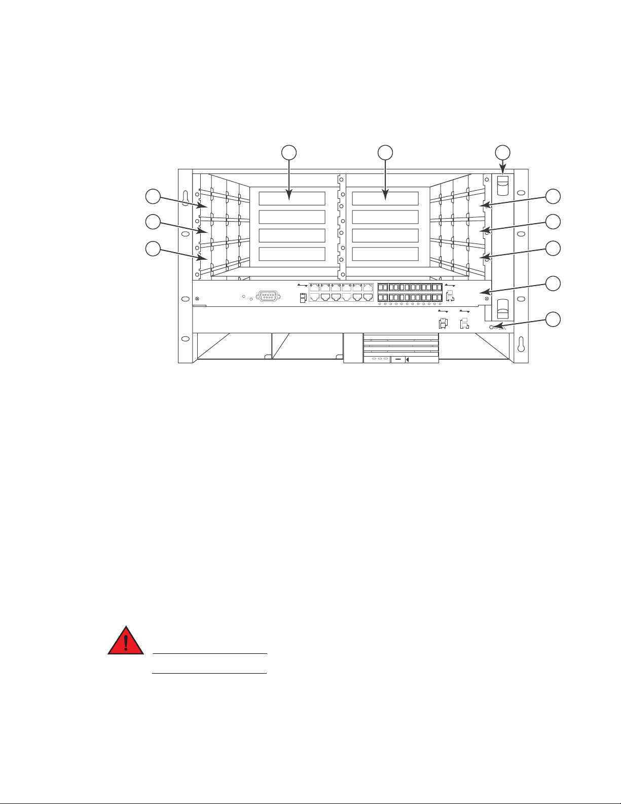
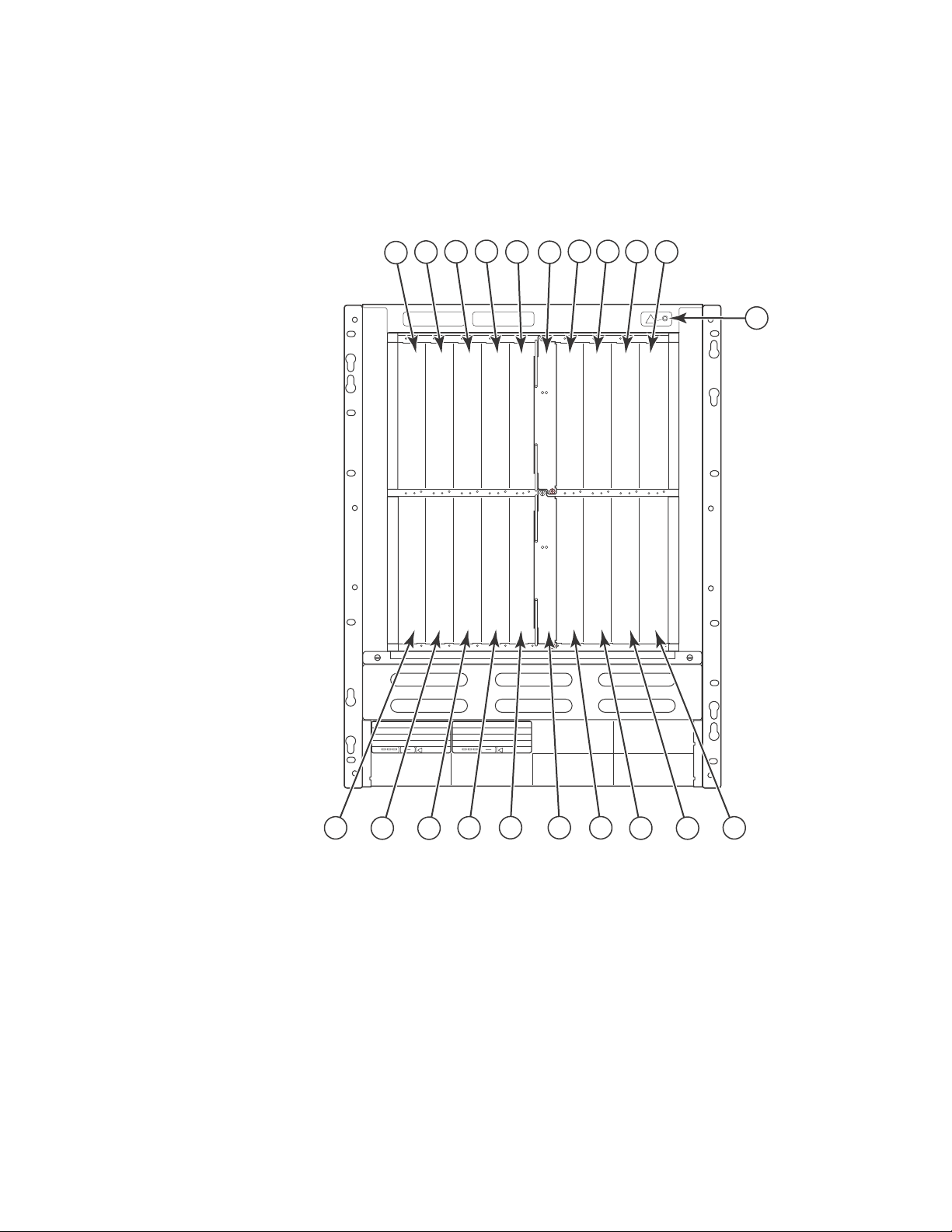
Figure 6 shows the chassis slots into which you can install the various modules and power
supplies.
FIGURE 6 FSX 1600 chassis slots
13579 1119 13 15 17
21
Active
Pwr
1
246810
1Interface slot 1
2Interface slot 2
3Interface slot 3
4Interface slot 4
5Interface slot 5
6Interface slot 6
7Interface slot 7
AC OKDC OK ALM
EJECT SYS
AC OKDC OK ALM
EJECT SYS
Active
Pwr
122014 16 18
Brocade FastIron X Series Chassis Hardware Installation Guide 11
53-1001723-02

Hardware features
DANGER
NOTE
NOTE
NOTE
1
8Interface slot 8
9 Management slot 9
10 Management slot 10
11 Interface slot 11
12 Interface slot 12
13 Interface slot 13
14 Interface slot 14
15 Interface slot 15
16 Interface slot 16
17 Interface slot 17
18 Interface slot 18
19 Switch fabric slot 1
20 Switch fabric slot 2
21 ESD connector
Figure 6 also shows an electrostatic discharge (ESD) connector, into which you can plug an ESD
wrist strap to ground yourself while handling and installing modules.
For safety reasons, the ESD wrist strap should contain a series 1 meg ohm resistor.
FSX 1600-ANR chassis
This section describes the differences between the FSX 1600-ANR chassis and the FSX 1600
chassis. For details about the similarities, refer to “FSX 1600-ANR chassis” on page 12.
The FSX 1600 Acoustic Noise-Reduced (ANR) chassis is an enhanced version of the FSX 1600
chassis. Part numbers for the FSX 1600-ANR chassis and bundles begin with FI-SX-1600-ANR-xxx
Except where explicitly noted throughout this manual, the FSX 1600 and FSX 1600-ANR chassis are
collectively referred to as the FSX 1600 chassis.
If you want to upgrade your existing FSX 1600 to an FSX 1600-ANR chassis, you must ship it to
Brocade, where an ANR kit will be installed, then the chassis will be shipped back to you. For more
information, contact Brocade
12 Brocade FastIron X Series Chassis Hardware Installation Guide
53-1001723-02
Hardware features
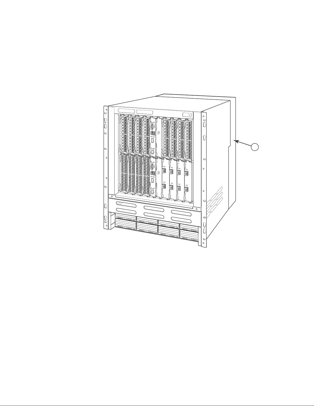
Compared to the FSX 1600, the FSX 1600-ANR has improved, redirected airflow, better thermal
dissipation, and reduced acoustic noise. The front of the FSX 1600-ANR chassis is identical to the
FSX 1600 and both chassis use the same switch fabric, management and interface modules, and
power supplies. Figure 7 shows the front of the chassis, including a partial view of the ANR kit,
which is behind the chassis.
1
FIGURE 7 FSX 1600-ANR chassis front
1
1 ANR kit on rear of chassis
Brocade FastIron X Series Chassis Hardware Installation Guide 13
53-1001723-02

Hardware features
1
The back of the FSX 1600-ANR chassis differs from the FSX 1600 chassis in that the FSX
1600-ANR has an extra sheet metal assembly (ANR kit) and different fan modules. The ANR kit
protrudes from the rear of the chassis, making the depth of the FSX 1600-ANR chassis four inches
longer than the FSX 1600 chassis. Figure 8 shows a side-by-side comparison of the FSX 1600 and
the FSX 1600-ANR.
FIGURE 8 Side-by-side comparison of the FSX 1600-ANR and FSX 1600 chassis
FSX 1600-ANR Chassis Rear View
The ANR chassis supports the same software release versions supported on the FSX 1600. The
display output for the CLI commands show chassis and show version identify the chassis as an
ANR chassis. Also, the SNMP object snChasType returns the chassis type ANR-Chassis. For details
about the show chassis command, refer to “Overview” on page 85. For details about the show
version command, refer to the section “Viewing System Information” in the FastIron Configuration
Guide.
FSX 1600 Chassis Rear View
Management modules
This section describes the management modules for the FastIron X Series chassis devices:
• The FSX chassis requires one management module. The management module occupies one
full slot.
• The FSX 800 and FSX 1600 chassis each require one management module and optionally
support two management modules for 100% redundancy. Each management module occupies
one half slot.
FSX management modules
The FSX management module has a built-in switch fabric module and comes with 12 combination
GbE Copper and Fiber ports.
14 Brocade FastIron X Series Chassis Hardware Installation Guide
53-1001723-02

Hardware features
NOTE
NOTE
NOTE
1
The FSX management module is dedicated, which means that it can be installed in the FSX chassis
only. If you attempt to install the FSX management module in the FSX 800, FSX 1600, or other
Brocade chassis, the chassis and module will not function properly.
Tab le 4 lists the management modules supported on the FSX chassis.
TABLE 4 FSX management modules
Part Number Microprocessor
Speed (MHz)
IPv4 Management Modules
SX-FI12GM-4 400 256
SX-FI12GM-4-PREM
SX-FI12GM2-4 466 512
SX-FI12GM2-4-PREM
IPv6 Management Modules
SX-FI12GM-6 400 256
SX-FI12GM-6-PREM
SX-FI12GM-6-PREM6
SX-FI12GM2-6 466 512
SX-FI12GM2-6-PREM
SX-FI12GM2-6-PREM6
MB SDRAM
The management modules with 512 MB SDRAM enable support for larger routing tables (1,000,000
BGP routes) with the full Layer 3 code.
The IPv6 management modules ending with -PREM provide additional support for full Layer 3 IPv4
routing protocols. The IPv6 management modules ending with -PREM6 provide additional support
for full Layer 3 IPv4 and IPv6 routing protocols.
The FSX management module does the following:
• Controls the FSX hardware components
• Houses and controls the switch fabric module
• Runs the networking protocols
• Provides the real time operating system
The management module is located in slot 9, just above the power supply slots (refer to Figure 2).
Brocade FastIron X Series Chassis Hardware Installation Guide 15
53-1001723-02
Hardware features
NOTE
NOTE
1
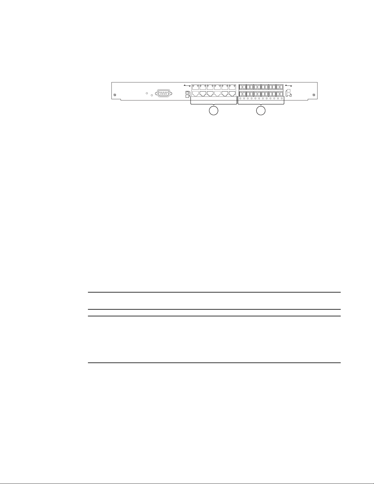
Figure 9 shows the management module’s front panel.
FIGURE 9 FSX management module front panel
8X-12GM-4
Odd
Pwr
Console
Even
Lnk
Odd
Even
Lnk
1 2
1 10/100/1000 Ethernet copper
2 Gigabit Ethernet fiber
The front panel includes the following control features:
• A Console port
• 12 combination GbE Copper and Fiber ports
• 25 LEDs – One LED for power, 12 LEDs for the copper ports, and 12 LEDs for the fiber ports
• A recessed reset button
Gigabit Ethernet ports on the FSX management module
The FSX management module’s front panel includes 12 combination copper and fiber Gigabit
Ethernet ports.
• RJ-45 copper interfaces for 1000Base-T, Cat5 copper cabling – The copper ports support
automatic MDI or MDIX detection, and use auto-sensing and auto-negotiating to determine the
speed (10, 100, or 1000 Mbps) and duplex mode (full-duplex or half-duplex) of the port at the
other end of the link, and adjust the port accordingly. Note that ports operating at 1000 Mbps
operate in the full-duplex mode only and cannot be modified.
• Mini-GBIC slots for the types of fiber cabling listed in Table 32 on page 168.
The Management Module does not support copper mini-GBICs.
Some older SFP modules (mini-GBICs for Gigabit Ethernet ports) have latching mechanisms which
are larger than the newer parts. These latches could interfere with one another when inserted side
by side into a module. Avoid using these mini-GBICs side by side in the same module. These older
modules are identified by the number PL-XPL-00-S13-22 or PL-XPL-00-L13-23 above the Serial
Number. All newer mini-GBICs do not have this limitation.
The Gigabit Ethernet fiber ports operate at a fixed speed of 1000 Mbps (they do not support 10
Mbps or 100 Mbps connections), and use auto-negotiation to automatically configure the highest
performance mode of inter-operation with the connected device.
One port out of each pair of copper and fiber ports can be active at a time. For example, you can
use either copper port 2 or fiber port 2, but not both at the same time. You can use a combination
of fiber and copper ports or all copper or all fiber ports, as needed.
16 Brocade FastIron X Series Chassis Hardware Installation Guide
53-1001723-02
Hardware features
NOTE
1
If you attach both the copper and fiber connectors for a port to the network, the fiber connector
takes precedence over the copper connector. These ports support true media automatic detection,
meaning the device selects the fiber or copper connector based on link availability. If a fiber link
cannot be established, the device selects the copper media.
Typical uses of these ports include but are not limited to the following:
• Connecting a PC through which you can access the system directly or through a Telnet
connection and configure, monitor, and manage the FSX system.
• Connecting a Gigabit Ethernet switch, which will provide connectivity to your existing
management network. You can then access the FSX system and configure, monitor, and
manage the system from a management station.
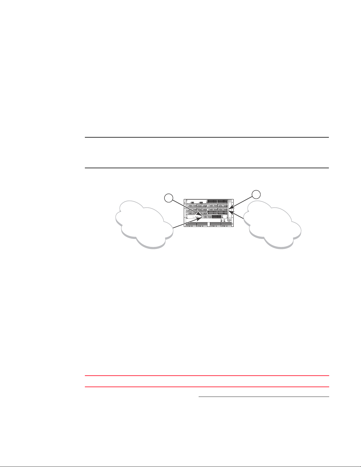
The existing management networks into which you can connect the Gigabit Ethernet ports must be
separate and isolated from the network over which user packets are switched and routed as shown
in Figure 10.
FIGURE 10 Separate management and switching or routing networks
Management
Network
1 Management port
2Interface port
FastIron Super X
1
d
FastIron SuperX
SYSEJECTSYSEJECTSYSEJECTSYSEJECT
2
t
Switching and
Routing Network
LEDs on the FSX management module
The FSX management module provides status information using the LEDs listed in Table 5. The
location of the LEDs is as follows:
• The fiber connectors use the LEDs located beneath the mini-GBIC slots.
• The copper connectors use square LEDs located in the upper right and left corners of the
upper Gigabit copper connectors. The LED on the left side is for the upper copper connector.
The LED on the right side is for the lower copper connector.
Tab le 5 describes the LEDs on the FSX management module.
TABLE 5 FSX management module LEDs
LED Description and Position State Meaning
Pwr Round LED located to the left
of the console port
Brocade FastIron X Series Chassis Hardware Installation Guide 17
53-1001723-02
On (Green) The module is receiving power.
Off The module is not receiving power.

Hardware features
NOTE
NOTE
NOTE
1
TABLE 5 FSX management module LEDs (Continued)
LED Description and Position State Meaning
10/100/1000
Mbps Copper
Ports (
1000 Mbps Fiber
Ports
Square LED located on upper
left corner of upper copper
connector for upper copper
connector
Square LED located on upper
right corner of upper copper
connector for lower copper
connector
Round LED located beneath
the fiber connectors
On (Green) A link is established with the remote
port.
Blinking The port is transmitting and receiving
traffic.
Off A link is not established with the
remote port.
On (Green) A link is established with the remote
port.
Blinking The port is transmitting and receiving
packets.
Off A link is not established with the
remote port.
Built-in switch fabric module
The switch fabric module switches user packets from one interface module installed in the chassis
to another. On the FSX, the switch fabric module is built into the management module.
Console port
The Console port on the management module is a standard DB-9 serial connector through which
you can attach a PC or terminal to configure the system using the command line interface (CLI).
The Console port interfaces the control plane only and not the data plane.
Reset button
The reset button on the management module allows you to restart the system. The reset button is
recessed to prevent it from being pushed accidentally.
The reset button is located next to the console port on the management module.
FSX 800 and FSX 1600 management modules
The management modules for the FSX 800 and FSX 1600 are interchangeable between devices.
Standard management modules provide Layer 2 and base Layer 3 functionality only. Premium
management modules support full Layer 3 functionality.
The FSX 800 and FSX 1600 management modules are dedicated, which means that you must
install them in the FSX 800 or FSX 1600 chassis only. If you attempt to install these management
modules in the FSX or other Brocade chassis, the chassis and modules will not function properly.
You cannot intermix different management modules in the same FSX 800 or FSX 1600 chassis. The
management modules must be of like-kind.
You cannot intermix IPv6 and IPv4 modules in the same FSX 800 or FSX 1600 chassis.
18 Brocade FastIron X Series Chassis Hardware Installation Guide
53-1001723-02
 Loading...