


Page 1

HARDWARE INSTALLATION GUIDE
Brocade FastIron SX Series Chassis
Hardware Installation Guide
Part Number: 53-1003613-04
Publication Date: 15 June 2017
Page 2

©
2017, Brocade Communications Systems, Inc. All Rights Reserved.
Brocade, the B-wing symbol, and MyBrocade are registered trademarks of Brocade Communications Systems, Inc., in the United States and in other
countries. Other brands, product names, or service names mentioned of Brocade Communications Systems, Inc. are listed at www.brocade.com/en/legal/
brocade-Legal-intellectual-property/brocade-legal-trademarks.html. Other marks may belong to third parties.
Notice: This document is for informational purposes only and does not set forth any warranty, expressed or implied, concerning any equipment,
equipment feature, or service oered or to be oered by Brocade. Brocade reserves the right to make changes to this document at any time, without
notice, and assumes no responsibility for its use. This informational document describes features that may not be currently available. Contact a Brocade
sales oce for information on feature and product availability. Export of technical data contained in this document may require an export license from the
United States government.
The authors and Brocade Communications Systems, Inc. assume no liability or responsibility to any person or entity with respect to the accuracy of this
document or any loss, cost, liability, or damages arising from the information contained herein or the computer programs that accompany it.
The product described by this document may contain open source software covered by the GNU General Public License or other open source license
agreements. To nd out which open source software is included in Brocade products, view the licensing terms applicable to the open source software, and
obtain a copy of the programming source code, please visit http://www.brocade.com/support/oscd.
2 Part Number: 53-1003613-04
Brocade FastIron SX Series Chassis Hardware Installation Guide
Page 3

Contents
Preface...................................................................................................................................................................................................................................7
Document conventions............................................................................................................................................................................................................................7
Notes, cautions, and warnings.....................................................................................................................................................................................................7
Text formatting conventions.........................................................................................................................................................................................................7
Command syntax conventions....................................................................................................................................................................................................8
Brocade resources.....................................................................................................................................................................................................................................8
Document feedback..................................................................................................................................................................................................................................8
Contacting Brocade Technical Support............................................................................................................................................................................................ 9
Brocade customers..........................................................................................................................................................................................................................9
Brocade OEM customers.............................................................................................................................................................................................................9
About This Document..................................................................................................................................................................................................... 11
Supported Software...............................................................................................................................................................................................................................11
What’s new in this document ............................................................................................................................................................................................................11
Overview.............................................................................................................................................................................................................................13
Hardware benets...................................................................................................................................................................................................................................13
Software features.....................................................................................................................................................................................................................................13
Supported congurations....................................................................................................................................................................................................................14
PoE and PoE+ applications....................................................................................................................................................................................................... 14
Hardware components..........................................................................................................................................................................................................................14
FSX 800 chassis........................................................................................................................................................................................................................... 15
FSX 1600 chassis........................................................................................................................................................................................................................ 17
Management modules................................................................................................................................................................................................................ 20
Switch fabric modules ................................................................................................................................................................................................................ 24
Interface modules..........................................................................................................................................................................................................................24
Network interfaces.........................................................................................................................................................................................................................34
Power supplies................................................................................................................................................................................................................................35
Cooling system...............................................................................................................................................................................................................................43
Built-in mounting brackets........................................................................................................................................................................................................ 44
FSX 1600 slot identication.....................................................................................................................................................................................................44
Installing FastIron SX Devices....................................................................................................................................................................................... 47
Unpacking the system.......................................................................................................................................................................................................................... 47
Installation precautions......................................................................................................................................................................................................................... 48
General precautions......................................................................................................................................................................................................................48
Lifting precautions.........................................................................................................................................................................................................................48
Power precautions and warnings............................................................................................................................................................................................48
Preparing the installation site..............................................................................................................................................................................................................50
Cabling infrastructure...................................................................................................................................................................................................................50
Installation location........................................................................................................................................................................................................................50
Removing extra shipment screws (FSX 800 only)....................................................................................................................................................................50
Installing the chassis in a rack............................................................................................................................................................................................................51
Installing mounting brackets on the FSX 1600 chassis...............................................................................................................................................53
Removing the slot panels....................................................................................................................................................................................................................55
Installing management and interface modules...........................................................................................................................................................................55
Attaching a management station......................................................................................................................................................................................................62
Attaching a PC or terminal to the console port or 10/100/1000 copper port................................................................................................. 63
Brocade FastIron SX Series Chassis Hardware Installation Guide
Part Number: 53-1003613-04 3
Page 4

Attaching a switch to an Ethernet port..................................................................................................................................................................................63
Powering on the system.......................................................................................................................................................................................................................63
Power cords.....................................................................................................................................................................................................................................64
Power source interruptions........................................................................................................................................................................................................66
Connecting AC power to the chassis.....................................................................................................................................................................................67
Connecting DC power to the chassis....................................................................................................................................................................................70
Verifying proper operation...................................................................................................................................................................................................................75
Observing the LEDs.....................................................................................................................................................................................................................75
Displaying the module status................................................................................................................................................................................................... 78
Connecting Network Devices and Checking Connectivity...................................................................................................................................... 81
Overview.....................................................................................................................................................................................................................................................81
Assigning permanent passwords.....................................................................................................................................................................................................81
Recovering from a lost password............................................................................................................................................................................................82
Conguring IP addresses.................................................................................................................................................................................................................... 83
IPv4 devices.................................................................................................................................................................................................................................... 83
IPv6 devices.................................................................................................................................................................................................................................... 85
Connecting network devices.............................................................................................................................................................................................................. 87
Cable specications......................................................................................................................................................................................................................87
Connecting to Ethernet or fast Ethernet hubs...................................................................................................................................................................87
Connecting to workstations, servers, or routers................................................................................................................................................................88
Connecting a network device to a ber port on the Brocade device....................................................................................................................... 89
Automatic MDI or MDIX detection.........................................................................................................................................................................................90
Using a CX4 transceiver.............................................................................................................................................................................................................90
Testing network connectivity.............................................................................................................................................................................................................. 92
Observing LEDs............................................................................................................................................................................................................................ 92
Troubleshooting network connections........................................................................................................................................................................................... 93
Support for digital optical monitoring....................................................................................................................................................................................94
Managing the Chassis and Modules.............................................................................................................................................................................95
Overview.....................................................................................................................................................................................................................................................95
Displaying chassis status and temperature readings...............................................................................................................................................................95
Managing the cooling system............................................................................................................................................................................................................99
Conguring the cooling system...............................................................................................................................................................................................99
Monitoring the cooling system..............................................................................................................................................................................................103
Displaying the Syslog conguration and static and dynamic buers.............................................................................................................................105
Static and dynamic buers.....................................................................................................................................................................................................106
Syslog messages for PCI (hardware) errors..............................................................................................................................................................................106
Managing the switch fabric modules (FSX 800 and FSX 1600 only)..........................................................................................................................107
Displaying management module CPU usage.........................................................................................................................................................................107
Removing MAC address entries....................................................................................................................................................................................................107
Using a Redundant Management Module................................................................................................................................................................109
Overview..................................................................................................................................................................................................................................................109
How Management module redundancy works....................................................................................................................................................................... 109
Management module redundancy overview...................................................................................................................................................................109
Management module switchover.........................................................................................................................................................................................110
Switchover implications............................................................................................................................................................................................................111
Management module redundancy conguration................................................................................................................................................................... 112
Changing the default active chassis slot...........................................................................................................................................................................112
Managing management module redundancy..........................................................................................................................................................................112
File synchronization between the active and standby management modules................................................................................................. 112
4 Part Number: 53-1003613-04
Brocade FastIron SX Series Chassis Hardware Installation Guide
Page 5

Manually switching over to the standby management module...............................................................................................................................115
Rebooting the active and standby management modules.......................................................................................................................................115
Monitoring management module redundancy........................................................................................................................................................................115
Determining management module status....................................................................................................................................................................... 116
Displaying temperature information....................................................................................................................................................................................117
Displaying switchover information.......................................................................................................................................................................................117
Maintaining the Hardware............................................................................................................................................................................................119
Overview..................................................................................................................................................................................................................................................119
Hardware maintenance schedule.................................................................................................................................................................................................. 119
Cleaning the ber optic connectors..............................................................................................................................................................................................119
Replacing a management module................................................................................................................................................................................................120
Installation precautions.............................................................................................................................................................................................................120
Removing a management module......................................................................................................................................................................................120
Installing a new management module...............................................................................................................................................................................121
Replacing a switch fabric module (FSX 800 and FSX 1600 only)................................................................................................................................ 124
Removing a switch fabric module....................................................................................................................................................................................... 124
Installing a new switch fabric module.................................................................................................................................................................................124
Replacing an interface module.......................................................................................................................................................................................................128
Precautions....................................................................................................................................................................................................................................128
Before removing an interface module............................................................................................................................................................................... 128
Removing an interface module.............................................................................................................................................................................................129
Installing a new interface module.........................................................................................................................................................................................129
Disabling and re-enabling an interface module.............................................................................................................................................................131
Replacing a copper or ber optic module..................................................................................................................................................................................132
Removing a copper or ber optic module.......................................................................................................................................................................132
Installing a new copper or ber optic module.................................................................................................................................................................133
Cabling a ber optic module..................................................................................................................................................................................................134
Installing or replacing a power supply......................................................................................................................................................................................... 134
Determining which power supply failed............................................................................................................................................................................134
Removing an AC power supply............................................................................................................................................................................................135
Removing a DC power supply..............................................................................................................................................................................................137
Installing a new power supply................................................................................................................................................................................................139
Connecting AC power to the chassis.................................................................................................................................................................................143
Connecting DC power to the chassis.................................................................................................................................................................................144
Verifying proper operation...................................................................................................................................................................................................... 148
Displaying the status of the power supplies....................................................................................................................................................................149
Replacing the FSX 800 fan tray....................................................................................................................................................................................................149
Replacing the FSX 1600 fan assemblies..................................................................................................................................................................................152
Replacing the air lter in the FastIron SX-1600..................................................................................................................................................................... 154
Mean time between failure...............................................................................................................................................................................................................155
Brocade FastIron SX Series Technical Specications............................................................................................................................................159
System specications.........................................................................................................................................................................................................................159
Ethernet....................................................................................................................................................................................................................................................159
LEDs..........................................................................................................................................................................................................................................................159
Other......................................................................................................................................................................................................................................................... 160
Weight and physical dimensions................................................................................................................................................................................................... 160
Environmental requirements........................................................................................................................................................................................................... 160
Power supply specications (per PSU).......................................................................................................................................................................................161
Power consumption (maximum conguration)........................................................................................................................................................................161
Brocade FastIron SX Series Chassis Hardware Installation Guide
Part Number: 53-1003613-04 5
Page 6

Serial port specications (DB9)..................................................................................................................................................................................................... 162
Serial port specications (pinout RJ-45)....................................................................................................................................................................................162
Serial port specications (protocol)...............................................................................................................................................................................................162
Memory specications.......................................................................................................................................................................................................................162
Regulatory compliance (EMC)........................................................................................................................................................................................................163
Regulatory compliance (safety)...................................................................................................................................................................................................... 163
Regulatory compliance (environmental)..................................................................................................................................................................................... 163
Additional pinout and signaling information............................................................................................................................................................165
Console (serial RJ45) management port pinouts.................................................................................................................................................................. 165
10/100 and gigabit port pinouts..................................................................................................................................................................................................166
Cable specications...................................................................................................................................................................................................... 167
Regulatory Statements.................................................................................................................................................................................................169
CE Statement.........................................................................................................................................................................................................................................169
China ROHS.......................................................................................................................................................................................................................................... 169
BSMI statement (Taiwan).................................................................................................................................................................................................................. 169
Canadian requirements......................................................................................................................................................................................................................170
China CC statement............................................................................................................................................................................................................................170
Europe and Australia (CISPR 22 Class A Warning)...............................................................................................................................................................171
FCC warning (US only)...................................................................................................................................................................................................................... 171
Germany..................................................................................................................................................................................................................................................171
KCC statement (Republic of Korea)..............................................................................................................................................................................................171
VCCI statement.....................................................................................................................................................................................................................................171
Caution and Danger Notices....................................................................................................................................................................................... 173
Cautions...................................................................................................................................................................................................................................................173
General cautions......................................................................................................................................................................................................................... 173
Electrical cautions.......................................................................................................................................................................................................................174
Danger Notices.....................................................................................................................................................................................................................................178
General dangers..........................................................................................................................................................................................................................179
Electrical dangers........................................................................................................................................................................................................................179
Dangers related to equipment weight................................................................................................................................................................................181
Laser dangers.............................................................................................................................................................................................................................. 182
6 Part Number: 53-1003613-04
Brocade FastIron SX Series Chassis Hardware Installation Guide
Page 7
Preface
• Document conventions......................................................................................................................................................................................7
• Brocade resources............................................................................................................................................................................................... 8
• Document feedback............................................................................................................................................................................................8
• Contacting Brocade Technical Support.......................................................................................................................................................9
Document conventions
The document conventions describe text formatting conventions, command syntax conventions, and important notice formats used in
Brocade technical documentation.
Notes, cautions, and warnings
Notes, cautions, and warning statements may be used in this document. They are listed in the order of increasing severity of potential
hazards.
NOTE
A Note provides a tip, guidance, or advice, emphasizes important information, or provides a reference to related information.
ATTENTION
An Attention statement indicates a stronger note, for example, to alert you when trac might be interrupted or the device might
reboot.
CAUTION
A Caution statement alerts you to situations that can be potentially hazardous to you or cause damage to hardware,
rmware, software, or data.
DANGER
A Danger statement indicates conditions or situations that can be potentially lethal or extremely hazardous to you. Safety
labels are also attached directly to products to warn of these conditions or situations.
Text formatting conventions
Text formatting conventions such as boldface, italic, or Courier font may be used to highlight specic words or phrases.
Format Description
bold text Identies command names.
Identies keywords and operands.
Identies the names of GUI elements.
Identies text to enter in the GUI.
italic text Identies emphasis.
Identies variables.
Identies document titles.
Courier font
Identies CLI output.
Brocade FastIron SX Series Chassis Hardware Installation Guide
Part Number: 53-1003613-04 7
Page 8

Brocade resources
Format Description
Identies command syntax examples.
Command syntax conventions
Bold and italic text identify command syntax components. Delimiters and operators
relationships.
Convention Description
bold text Identies command names, keywords, and command options.
italic text Identies a variable.
value In Fibre Channel products, a xed value provided as input to a command option is printed in plain text, for
example, --show WWN.
[ ] Syntax components displayed within square brackets are optional.
Default responses to system prompts are enclosed in square brackets.
{ x | y | z } A choice of required parameters is enclosed in curly brackets separated by vertical bars. You must select
one of the options.
In Fibre Channel products, square brackets may be used instead for this purpose.
x | y A vertical bar separates mutually exclusive elements.
< > Nonprinting characters, for example, passwords, are enclosed in angle brackets.
... Repeat the previous element, for example, member[member...].
\ Indicates a “soft” line break in command examples. If a backslash separates two lines of a command
input, enter the entire command at the prompt without the backslash.
dene groupings of parameters and their logical
Brocade resources
Visit the Brocade website to locate related documentation for your product and additional Brocade resources.
White papers, data sheets, and the most recent versions of Brocade software and hardware manuals are available at www.brocade.com.
Product documentation for all supported releases is available to registered users at MyBrocade.
Click the Support tab and select Document Library to access product documentation on MyBrocade or www.brocade.com. You can
locate documentation by product or by operating system.
Release notes are bundled with software downloads on MyBrocade. Links to software downloads are available on the MyBrocade landing
page and in the Document Library.
Document feedback
Quality is our
However, if you nd an error or an omission, or you think that a topic needs further development, we want to hear from you. You can
provide feedback in two ways:
• Through the online feedback form in the HTML documents posted on www.brocade.com
• By sending your feedback to documentation@brocade.com
Provide the publication title, part number, and as much detail as possible, including the topic heading and page number if applicable, as
well as your suggestions for improvement.
8 Part Number: 53-1003613-04
rst concern at Brocade, and we have made every eort to ensure the accuracy and completeness of this document.
Brocade FastIron SX Series Chassis Hardware Installation Guide
Page 9

Contacting Brocade Technical Support
Contacting Brocade Technical Support
As a Brocade customer, you can contact Brocade Technical Support 24x7 online or by telephone. Brocade OEM customers should
contact their OEM/solution provider.
Brocade customers
For product support information and the latest information on contacting the Technical Assistance Center, go to www.brocade.com and
select Support.
If you have purchased Brocade product support directly from Brocade, use one of the following methods to contact the Brocade
Technical Assistance Center 24x7.
Online Telephone
Preferred method of contact for non-urgent issues:
• Case management through the MyBrocade portal.
• Quick Access links to Knowledge Base, Community, Document
Library, Software Downloads and Licensing tools
Required for Sev 1-Critical and Sev 2-High issues:
• Continental US: 1-800-752-8061
• Europe, Middle East, Africa, and Asia Pacic: +800-AT FIBREE
(+800 28 34 27 33)
• Toll-free numbers are available in many countries.
• For areas unable to access a toll-free number:
+1-408-333-6061
Brocade OEM customers
If you have purchased Brocade product support from a Brocade OEM/solution provider, contact your OEM/solution provider for all of
your product support needs.
• OEM/solution providers are trained and
• Brocade provides backline support for issues that cannot be resolved by the OEM/solution provider.
• Brocade Supplemental Support augments your existing OEM support contract, providing direct access to Brocade expertise.
For more information, contact Brocade or your OEM.
• For questions regarding service levels and response times, contact your OEM/solution provider.
certied by Brocade to support Brocade® products.
Brocade FastIron SX Series Chassis Hardware Installation Guide
Part Number: 53-1003613-04 9
Page 10

10 Part Number: 53-1003613-04
Brocade FastIron SX Series Chassis Hardware Installation Guide
Page 11

About This Document
• Supported Software..........................................................................................................................................................................................11
• What’s new in this document .......................................................................................................................................................................11
Supported Software
For information about the features supported on a hardware platform, refer to the appropriate Features and Standards Support Matrix
document.
What’s new in this document
There are no enhancements in this edition.
Brocade FastIron SX Series Chassis Hardware Installation Guide
Part Number: 53-1003613-04 11
Page 12

12 Part Number: 53-1003613-04
Brocade FastIron SX Series Chassis Hardware Installation Guide
Page 13

Overview
• Hardware benets..............................................................................................................................................................................................13
• Software features............................................................................................................................................................................................... 13
• Supported congurations...............................................................................................................................................................................14
• Hardware components....................................................................................................................................................................................14
This chapter contains an overview of the following FastIron X Series® Layer 2 or Layer 3 switches:
• FastIron SX 800 (FSX 800)
• FastIron SX 1600 (FSX 1600)
Designed for medium to large enterprise backbones, FastIron X Series chassis devices are modular switches that provide the enterprise
network with a complete end-to-end Enterprise LAN solution, from the wiring closet to the LAN backbone.
Hardware benets
FastIron X Series chassis devices provide the following benets:
• The FSX 800 and FSX 1600 management modules have a console port and a 10/100/1000 port that provide connectivity
to your existing management network.
• The FSX 800 and FSX 1600 management modules are interchangeable between devices. However, you cannot mix Second
Generation and Third Generation modules in the same device.
• Optional dual management modules on the FSX 800 and FSX 1600 provide full redundancy.
• The crossbar (xbar) architecture enables the management module to switch 30 Gigabits per second between each interface
module and within the management module to each of the fabrics.
• The interface modules and power supplies are interchangeable among all FastIron X Series chassis devices. However, you
cannot mix Second Generation and Third Generation modules in the same device.
• The FSX 800 and FSX 1600 management, switch fabric, and interface modules are hot swappable, which means you can
remove and replace them while the device is powered on and running.
• All FastIron X Series chassis devices have a passive backplane.
• FastIron X Series chassis devices have completely separate data and control planes for uncompromised switching performance,
increased reliability of both planes, and increased security of the control plane in the event of a Denial of Service (DoS) attack on
the data plane.
• FastIron X Series chassis devices have distributed data and control planes, which results in uncompromised wire-speed
performance for the data plane and faster and more ecient performance of management functions for the control plane.
• The SX-FI-ZMR modules will work with systems with all second generation packet processor modules or all third generation
packet processor modules. The SX-FI-2XMR modules will only work with all third generation packet processor modules.
Software features
Software features
installed in the device. Refer to the appropriate conguration guide for a complete list of software features supported on your device.
Brocade FastIron SX Series Chassis Hardware Installation Guide
Part Number: 53-1003613-04 13
dier depending on the software version that is loaded on the device and the type of management module that is
Page 14

Supported congurations
Supported congurations
Premium FastIron X Series chassis devices support Layer 2 switching and full Layer 3 multiprotocol routing. Standard devices support
Layer 2 and base Layer 3 switching. All standard FastIron X Series chassis devices can be upgraded to full Layer 3 multi-protocol
routing, at which time they are considered to be premium devices.
For a list of supported modules and management modules refer to the “Management Modules” section.
All FastIron X Series chassis devices optionally support Power over Ethernet (PoE), providing the means for integrating data, voice, and
video over existing Ethernet cables.
TABLE 1 FastIron X Series supported congurations
Device Standard Premium (PREM) Power over Ethernet (PoE and PoE
+)
FSX 800 Yes Yes Yes (FI-SX-24-GPP and FI-
SX48GPP modules only)
FSX 1600 Yes Yes Yes (FI-SX-24-GPP and FI-
SX48GPP modules only)
PoE and PoE+ applications
Brocade FastIron X Series chassis devices with PoE and PoE+ provide Power over Ethernet, compliant with the standards described in
the IEEE 802.3af and 802.3at
existing network cabling infrastructure, enabling multicast-enabled full streaming audio and video applications for converged services,
such as, Voice over IP (VoIP), WLAN access points, IP surveillance cameras, and other IP technology devices.
PoE technology eliminates the need for an electrical outlet and dedicated UPS near IP powered devices. With power sourcing devices,
such as Brocade’s FastIron X Series chassis devices with PoE and PoE+, power is consolidated and centralized in the wiring closets,
improving the reliability and resiliency of the network. Because PoE can provide power over Ethernet cable, power is continuous, even in
the event of a power failure.
For PoE port density, refer to PoE port density on page 43. For PoE+ port density, refer to PoE+ port density on page 43.
specication for delivering in-line power. The specications dene the standard for delivering power over
Hardware components
FastIron X Series chassis devices are composed of the following major hardware components:
• Chassis
• Management module, with optional dual management modules for full redundancy
• Separate switch fabric modules (FSX 800 and FSX 1600 only)
• Interface modules
• Power supplies
• In the FSX 800, a fan tray comprised of six fans and a fan control module
• In the FSX 1600, two fan trays at the rear of the chassis and an air
• Built-in mounting brackets
lter in the bottom front of the chassis
The following sections provide more information about these components.
For details about physical dimensions, power supply specications, and pinouts, refer to the “Hardware Specications” section.
14 Part Number: 53-1003613-04
Brocade FastIron SX Series Chassis Hardware Installation Guide
Page 15
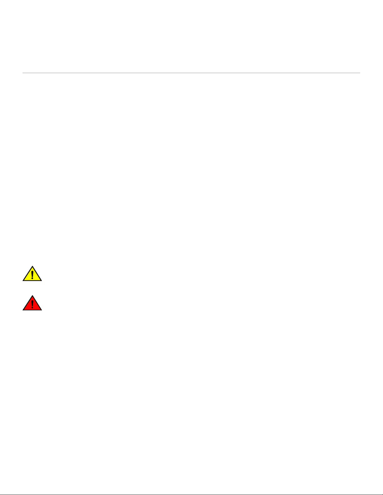
Hardware components
FSX 800 chassis
The FSX 800 chassis is six rack units in height and contains the following component slots:
• Two half slots for management modules
• Two half slots for switch fabric modules
• Eight half slots for interface modules
• Four slots for power supplies along the bottom of the card shelf. The power supply slots add a rack unit (RU) to the height of the
chassis.
FIGURE 1 FSX 800 chassis and component slots
The FSX 800 chassis ships from the factory with the following components installed:
• Two switch fabric modules
• A slot panel in each empty interface module slot and power supply slot. The slot panels ensure proper airow within the chassis.
• One AC power supply
• A fan tray assembly, which contains the cooling system for the chassis
Brocade FastIron SX Series Chassis Hardware Installation Guide
Part Number: 53-1003613-04 15
Page 16
Hardware components
You can install the following components in the FSX 800 slots:
• Up to two management modules
• Up to eight single slot and up to 4 double slot interface modules
• Up to four AC or DC power supplies: two system (12-volt) power supplies and two PoE (52- 54-volt) power supplies
Before installing any modules or power supplies, you must remove the slot panel.
CAUTION
If you do not install a module or a power supply in a slot, you must keep the slot ller panel in place. If you run the chassis
with an uncovered slot, the system will overheat.
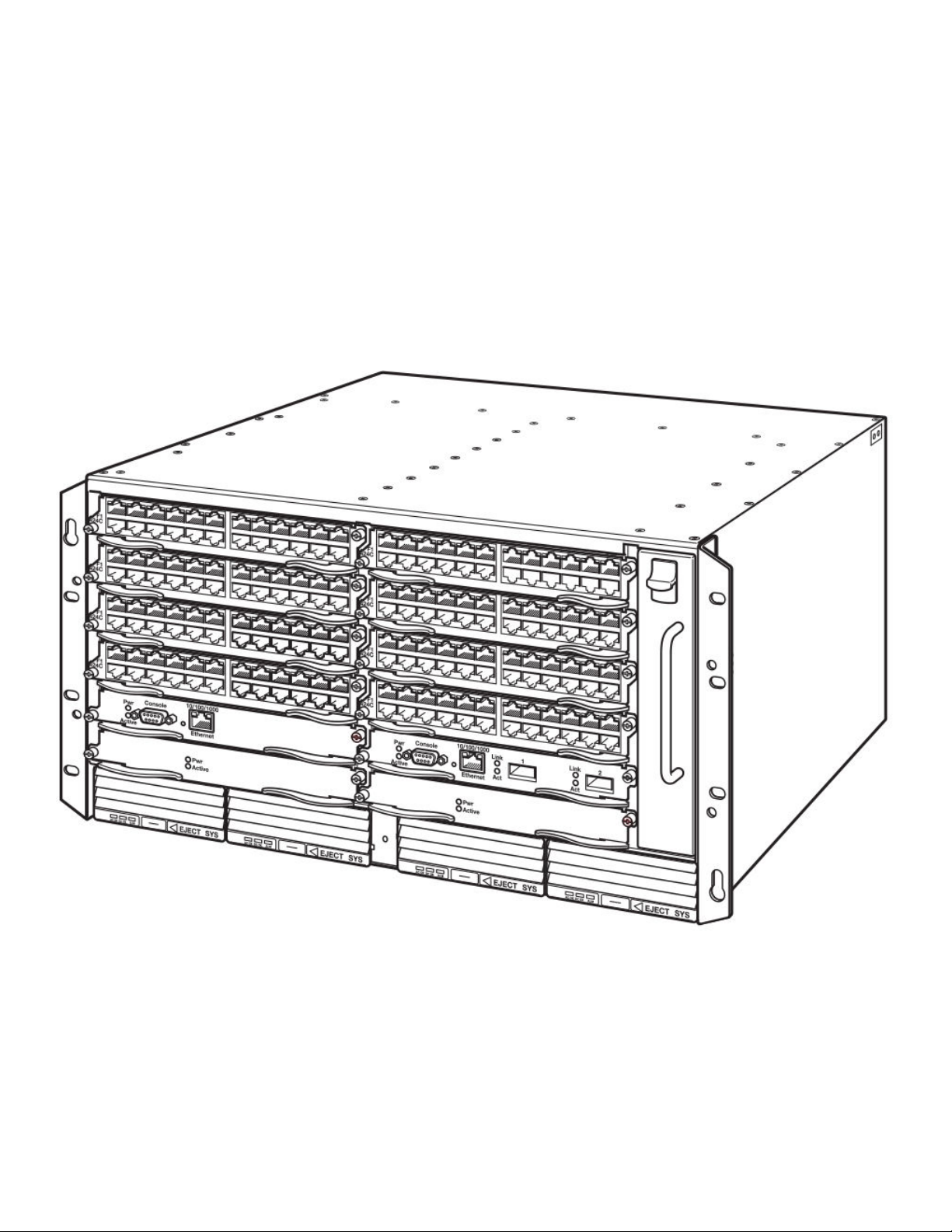
The gure below shows the FSX 800 slots where you install modules and power supplies, and the electrostatic discharge (ESD)
connector, into which you can plug an ESD wrist strap to ground yourself while handling and installing modules.
FIGURE 2 FSX 800 module slots
1. Slot 1
2. Slot 2
3. Slot 3
4. Slot 4
5. Slot 5
6. Slot 6
7. Slot 7
16 Part Number: 53-1003613-04
8. Slot 8
9. Slot 9
10. Slot 10
11. Switch Fabric Slot 1
12. Switch Fabric Slot 2
13. Fan tray
14. ESD connector
Brocade FastIron SX Series Chassis Hardware Installation Guide
Page 17

DANGER
For safety reasons, the ESD wrist strap should contain a series 1 megaohm resistor.
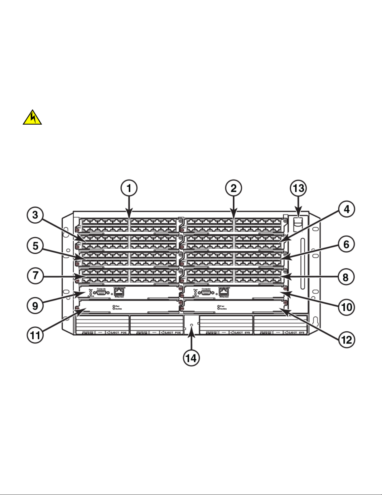
FSX 1600 chassis
Part numbers for the FSX 1600 chassis and bundles begin with FI-SX-1600-xxx.
The FSX 1600 chassis is 14 rack units in height and contains the following component slots:
• Two half slots for management modules
• Two half slots for switch fabric modules
• Sixteen half slots for interface modules
• Eight slots for power supplies along the bottom of the card shelf
The following gure shows the front of the FSX 1600 device.
Hardware components
Brocade FastIron SX Series Chassis Hardware Installation Guide
Part Number: 53-1003613-04 17
Page 18
Hardware components
FIGURE 3 FSX 1600 device
18 Part Number: 53-1003613-04
Brocade FastIron SX Series Chassis Hardware Installation Guide
Page 19
Hardware components
FSX 1600 devices ship from the factory with the following components installed:
• Two switch fabric modules
• A slot panel in each empty interface module slot and power supply slot. The slot panel ensures proper airow within the chassis.
• Two AC power supplies
• A fan tray assembly, which contains the cooling system for the chassis
You can install the following components in the slots:
• Up to two management modules
• Up to 16 single slot and up to 8 double slot interface modules
• Up to eight AC or DC power supplies (four system (SYS) power supplies and four PoE power supplies)
Before installing any modules or power supplies, you must remove the slot panel.
CAUTION
If you do not install a module or a power supply in a slot, you must keep the slot ller panel in place. If you run the chassis
with an uncovered slot, the system will overheat.
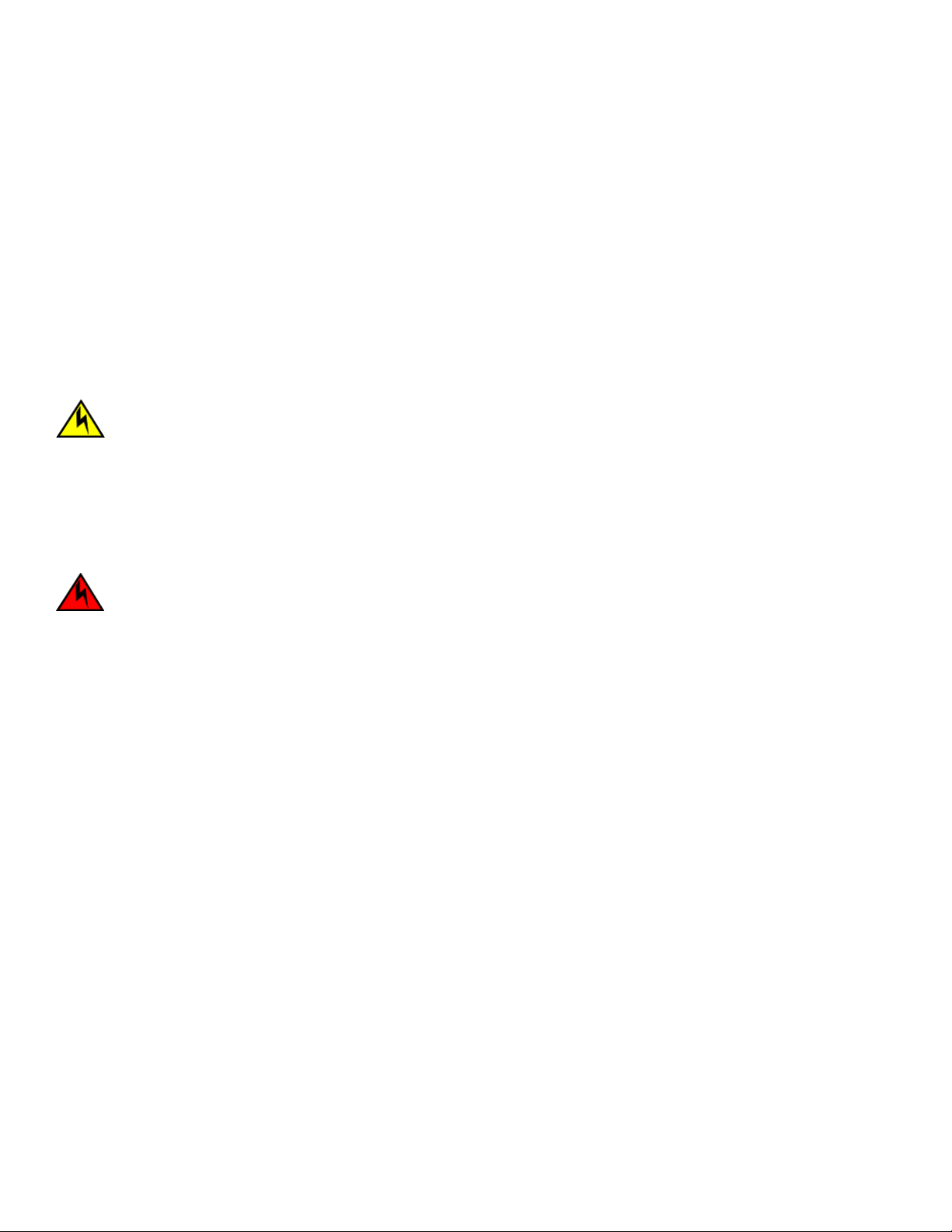
FSX 1600 slot identication
The following gure identies the slots where you can install modules and power supplies as well as the electrostatic discharge (ESD)
connector, into which you can plug an ESD wrist strap to ground yourself while handling and installing modules.
DANGER
For safety reasons, the ESD wrist strap should contain a series 1 megaohm resistor.
Brocade FastIron SX Series Chassis Hardware Installation Guide
Part Number: 53-1003613-04 19
Page 20
Hardware components
FIGURE 4 FSX 1600 slots
1. Interface slot 1
2. Interface slot 2
3. Interface slot 3
4. Interface slot 4
5. interface slot 5
6. Interface slot 6
7. Interface slot 7
8. Interface slot 8
9. Interface slot 9
10. Interface slot 10
11. Interface slot 11
12. Interface slot 12
13. Interface slot 13
14. Interface slot 14
15. Interface slot 15
16. Interface slot 16
17. Management slot 17
18. Management slot 18
19. Switch fabric slot 1
20. Switch fabric slot 2
21. ESD ground connector
Management modules
Each FSX 800 and FSX 1600 device requires one management module and as an option supports two management modules for full
redundancy. Each management module occupies one half slot.
20 Part Number: 53-1003613-04
Brocade FastIron SX Series Chassis Hardware Installation Guide
Page 21

Hardware components
FSX 800 and FSX 1600 management modules
Management modules for the FSX 800 and FSX 1600 are interchangeable between devices. Standard management modules provide
Layer 2 and base Layer 3 functionality only. Premium management modules support full Layer 3 functionality.
NOTE
FSX 800 and FSX 1600 management modules are dedicated, which means that you must install them in FSX 800 or FSX
1600 devices only. If you attempt to install these management modules in any other Brocade device, the device and modules
will not function properly.
NOTE
You cannot mix dierent management modules in the same FSX 800 or FSX 1600 device. The management module models
must be identical.
NOTE
You cannot mix Second Generation and Third Generation modules in the same FSX 800 or FSX 1600 device.
Table 2 lists the management modules for FSX 800 and FSX 1600 devices.
TABLE 2 Information about FSX 800 and FSX 1600 management modules
Part Number Description Microprocessor Speed (MHz) MB SDRAM
XL management modules
SX-FI-ZMR-XL no ports 1500 (quad-core) 4096
SX-FI-ZMR-XL-PREM6
SX-FI-2XGMR-XL 2 ports
SX-FI-2XGMR-XL-PREM
NOTE
XL management modules ending with -PREM6 support full Layer 3 IPv4 and IPv6 routing protocols.
FSX 800 and FSX 1600 management modules perform the following tasks:
• Control the hardware components
• Control the separate switch fabric modules
• Run the networking protocols
• Provide the real time operating system
FSX 800 management modules are located in slots 9 and 10, just above the switch module slots (refer to FSX 800 chassis on page
15).
FSX 1600 management modules are located in slots 17 and 18 along the edge of the device (refer to FSX 1600 chassis on page 17).
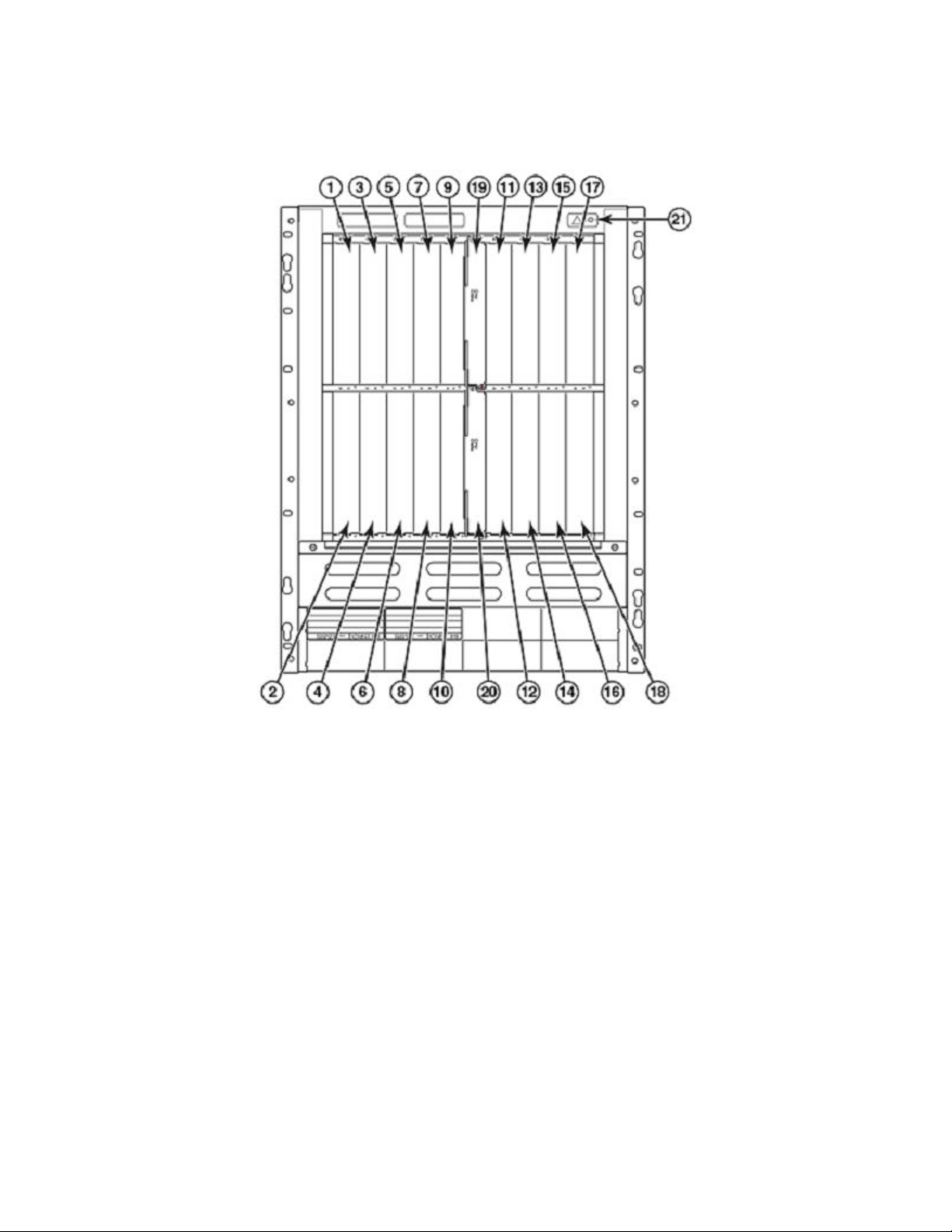
The gure below shows the front panel of the IPv6 SX-FI-ZMR-XL and SX-FI-ZMR-XL-PREM6 management modules with no ports.
Brocade FastIron SX Series Chassis Hardware Installation Guide
Part Number: 53-1003613-04 21
Page 22
Hardware components
FIGURE 5 SX-FI-ZMR-XL and SX-FI-ZMR-XL-PREM6 management modules with no ports
The gure below shows the front panel of the IPv6 SX-FI-2XGMR-XL and SX-FI-2XGMR-XL-PREM management modules with 2
ports.
FIGURE 6 SX-FI-2XGMR-XL and SX-FI-2XGMR-XL-PREM management modules with 2 ports
Management module front panels include the following control features:
• A Console port and 10/100/1000 RJ-45 copper port allow you to access the command line interface (CLI) directly from a PC
or terminal or through a Telnet connection.
• LEDs for power and active or standby status.
• The SX-FI-ZMR-XL and SX-FI-ZMR-PREM6 management modules and the SX-FI-2XGMR-XL and SX-FI-2XGMR-XLPREM management modules have a USB port on the front panel for externally accessible customer Flash Memory.
10/100/1000 GbE copper port on the FSX 800 and FSX 1600 management modules
The 10/100/1000 RJ45 copper port on the management module enables you to attach a PC or terminal and access the system CLI
directly or through a Telnet connection.
LEDs on the FSX 800 and FSX 1600 management modules
The management modules provide status information through the LEDs listed in the table below.
TABLE 3 FSX 800 and FSX 1600 management module LEDs
LED Description and Position State Meaning
Pwr Round LED located to the left of
the console port
Active Round LED located to the left of
the console port
10/100/1000 Copper Port LEDs on SX-FI-ZMR-XL and SX-FI-ZMR-XL-PREM6 modules only
MGMT-Link Right-most LED above the port On (Green) 10/100/1000
On (Green) The module is receiving power.
O The module is not receiving power.
On (Green) The module is the active
management module.
O The module is not the active
management module.
22 Part Number: 53-1003613-04
Brocade FastIron SX Series Chassis Hardware Installation Guide
Page 23

Hardware components
TABLE 3 FSX 800 and FSX 1600 management module LEDs (continued)
LED Description and Position State Meaning
Blinking The port is transmitting and
receiving trac.
O No port connection exists.
Sync-Link Left-most LED above the port On (Green) Two management modules are
present.
Blinking Active and Standby modules are
syncing.
O No port connection exists.
SFP+ port LEDs on SX-FI-2XGMR-XL and SX-FI-2XGMR-XL-PREM management modules only
Port 1 Left SFP+ On (Green) The SFP+ port is linked.
Blinking The SFP+ port has TX/RX activity.
O The SFP+ port is not linked.
Port 2 Right SFP+ On (Green) The SFP+ port is linked.
Blinking The SFP+ port has TX/RX activity.
O The SFP+ port is not linked.
Console port
The Console port on SX-FI-ZMR-XL and SX-FI-ZMR-XL-PREM6 management modules and the SX-FI-2XGMR-XL and SXFI-2XGMR-XL-PREM management modules has an RJ45 connector.
The Console port interfaces with the control plane only and does not interface with the data plane.
Reset button
The SX-FI-ZMR-XL and SX-FI-ZMR-XL-PREM6 management modules and the SX-FI-2XGMR-XL and SX-FI-2XGMR-XL-PREM
management modules do not have a reset button.
Specifying a port address
You can specify a port address for a data port or a management port.
Specifying a management port
The management port number is always 1. This example shows how to specify the management port:
Brocade (config) # interface management 1
Specifying a data port
The port address format is slot /port.
• Slot species the interface slot number. Range is from 1 to 8 (FSX 800) or 1 to 16 (FSX 1600).
• Port species the port number in the slot. Range is from 1 to 48 depending on the interface module.
This example shows how to specify port 2 in slot 1:
Brocade (config) # interface ethernet 1/2
Brocade FastIron SX Series Chassis Hardware Installation Guide
Part Number: 53-1003613-04 23
Page 24
Hardware components
Switch fabric modules
Switch fabric modules switch user packets from one interface module to another. Switch fabric modules in the FSX 800 and FSX 1600
devices are separate and are located next to the management modules in the device.
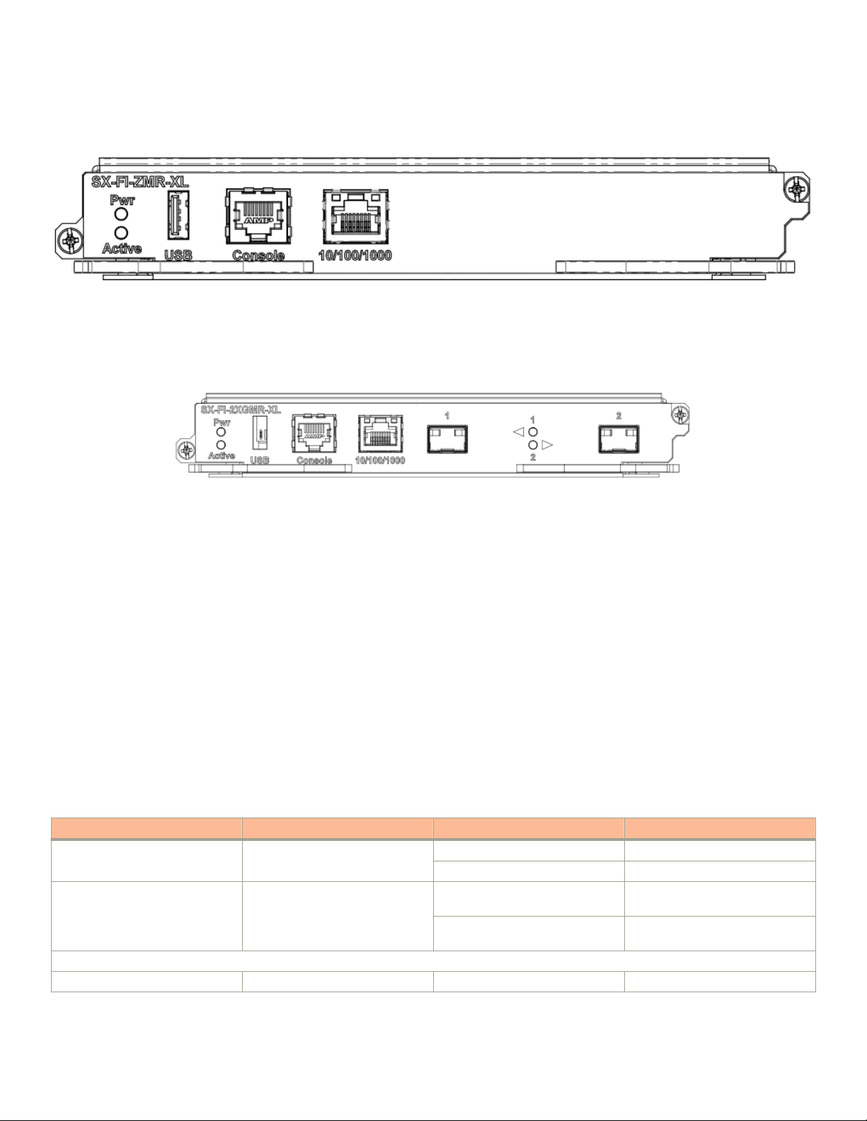
Switch fabric modules shows an FSX 800 and FSX 1600 switch fabric module front panel.
FIGURE 7 FSX 800 and FSX 1600 switch fabric module front panel
Switch fabric module LEDs
The front panel provides status information through the LEDs listed in the table below.
TABLE 4 Switch fabric module LEDs
LED Description and Position State Meaning
Pwr Top LED On (Green) The module is receiving power.
O The module is not receiving power.
Active Bottom LED On (Green) The module is functioning properly.
O The module is not functioning
properly.
Interface modules
This section describes interface modules for the FastIron X Series chassis devices. The following installation rules apply:
• In the FSX 800 device, you can install up to eight single slot and four double interface modules in the slots shown in FSX 800
chassis on page 15.
• In the FSX 1600 device, you can install up to 16 single slot and eight double slot interface modules in the slots shown in FSX
1600 chassis on page 17.
NOTE
You cannot mix Second Generation and Third Generation modules in the same device.
The table below lists the supported interface modules for each FastIron X Series chassis device type.
TABLE 5 Interface modules
Interface Module Part Number FSX 800 FSX 1600
Second Generation Interface Modules
24-port Gigabit Ethernet copper
without PoE
24-port Gigabit Ethernet copper
with PoE
SX-FI624C X X
SX-FI624P X X
24 Part Number: 53-1003613-04
Brocade FastIron SX Series Chassis Hardware Installation Guide
Page 25

TABLE 5 Interface modules (continued)
Interface Module Part Number FSX 800 FSX 1600
24-port 100/1000 Hybrid Fiber SX-FI624HF X X
2-port 10-Gigabit Ethernet LAN
module
Third Generation Interface Modules
24-port Gigabit Ethernet copper
interface module with PoE+
24-port Gigabit Ethernet ber
interface module
2-port 10-Gigabit Ethernet
interface module
8-port 10-Gigabit Ethernet
interface module
48-port 10/100/1000 Mbps
RJ45 Ethernet module with PoE+
48-port 10/100/1000 Gigabit
Ethernet copper without POE
48-port 10/100/1000 Gigabit
Ethernet copper with POE
SX-FI62XG X X
SX-FI-24GPP X X
SX-FI-24HF X X
SX-FI-2XG X X
SX-FI-8XG X X
SX-FI48GPP X X
SX-FI648C X X
SX-FI648PP X X
Hardware components
Hot swap support
• Interface modules are hot swappable, which means you can remove and replace them without powering down the system;
however, you must issue the disable module command before you remove the modules from the device.
• Issuing the disable module command before removing the module is not required on the FSX 800 and FSX 1600 device. This
is referred to as "Enhanced Hot Swap".
• Do not perform both hot swap removal and hot swap insertion of another line module while hot swap of a line module is taking
place. Wait until the current hot swap of the line module is completed. The following message indicates that the hot swap
insertion of a module is completed:
Module 1 is up and running
The following console message indicates that the hot swap removal of a module is completed:
Powering off the module in slot 1
NOTE
It is recommended that modules be disabled through the CLI before removal from the device. If the operator wishes to remove
the module without rst disabling the module, the Enhanced Hot Swap capability in software Release 03.2.00 and later
supports this procedure for the FastIron SX 800 and FastIron SX 1600 device. Enhanced Hot Swap (that is, no CLI disable )
should be performed during a maintenance window. On rare occasions, an Enhanced Hot Swap may result in a software reload
of the system. The likelihood of this event is very low.
NOTE
It is important to wait a minimum of 10 seconds between the removal and insertion of a line module. Re-insertion of a line
module less than 10 seconds after the removal of a line module may result in the line module not being properly recognized.
Refer to Replacing an interface module on page 128 for instructions.
Brocade FastIron SX Series Chassis Hardware Installation Guide
Part Number: 53-1003613-04 25
Page 26
Hardware components
48-port 10/100/1000 Mbps (RJ45) Ethernet PoE interface module
The 48-port 10/100/1000 Mbps Ethernet PoE interface module (SX-FI48GPP) uses two vertical half-slots in the FastIron SX 800 or
1600 device and is supported in IPv4-only and IPv6-capable systems. The ports support automatic MDI or MDIX detection, and use
auto-sensing and auto-negotiating to determine the speed (10, 100, or 1000 Mbps) and duplex mode (full-duplex or half-duplex) of the
port at the other end of the link, and adjust the local port accordingly. Ports running at 1000 Mbps operate in full-duplex mode only and
cannot be modied.
The module is 2:1 oversubscribed with an intelligent queue in front of the module packet processor. Trac on each port can be classied
as high or low priority, and can be scheduled from a queue using these priority settings ensuring QoS from the port of entry into the
network.
2:1 oversubscription
Interface oversubscription is the use of a single physical ingress port to handle incoming trac from multiple devices, and is usually
expressed as a ratio; the ratio shows the proportion of incoming connections to physical ports carrying trac to the backplane of the
device. The FastIron supports 2:1 oversubscription, allowing two devices to pass trac through a single internal physical port to take
advantage of bandwidth which might otherwise go unused.
Oversubscription is achieved on the SX-FI48GPP by connecting 48 external ports to 24 internal physical ports, providing 2:1
oversubscription. No CLI command is required to enable oversubscription, but because two external ports are funneling trac into each
physical link, the FastIron uses virtual interfaces (VEs) to divide each physical link into two logical ports. These VEs can then be
individually
congured at the interface level.
NOTE
This interface module is supported only on the FSX-800 and FSX-1600.
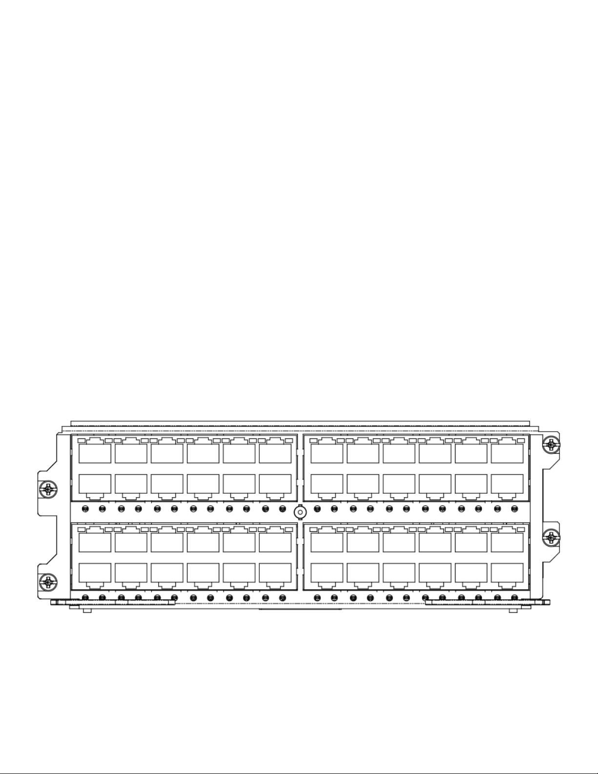
FIGURE 8 48-port 10/100/1000 Mbps Ethernet PoE interface module front panel
LEDs for the 48-port 10/100/1000 Mbps Ethernet PoE interface module
The front panel of the 48-port 10/100/1000 Mbps Ethernet interface module includes 48 LEDs that indicate the status of each port,
and 48 LEDs that indicate the status of PoE+. The
located below the remaining 24 ports.
26 Part Number: 53-1003613-04
rst 24 LEDs are located below the rst 24 ports and the remaining 24 LEDs are
Brocade FastIron SX Series Chassis Hardware Installation Guide
Page 27

Hardware components
NOTE
The PoE LEDs work only when PoE is enabled on your device.
The 48-port 10/100/1000 Mpbs Ethernet PoE interface module supports Power over Ethernet (PoE+). To run PoE+ on your system,
you must also install at least one 48-volt to 54-volt power supply.
The module ports provide status information through the LEDs described in the table below.
TABLE 6 LEDs for the 48-port 10/100/1000 Mbps Ethernet PoE interface module
LED Position State Meaning
Link or Activity Square LED located at upper left
corner of top port (for top port)
Square LED located at upper right
corner of top port (for bottom port)
PoE (if applicable) Round LED located beneath the
ports. The rst (left-most) LED is
for port 1, the second LED is for
port 2, the third LED is for port 3,
etc.
On (Green) A link is established with the remote
port.
Blinking The port is transmitting and
receiving trac.
O No link exists with the remote port.
On (Green) The port is enabled, a power-
consuming device has been
detected, and the module is
supplying power to the device.
O The port is not providing in-line
power.
NOTE
This module occupies two slot spaces, and can be installed in certain slots only. For details refer to Installing management and
interface modules on page 55.
48-port 10/100/1000 Mbps Ethernet PoE+ interface module limitations
The following limitations apply to this module:
• Q-in-Q and SAV (VLAN stacking) are not supported on this module
Second Generation 24-port Gigabit Ethernet copper interface module
The Second Generation 24-port Gigabit Ethernet copper interface module has 24 10/100/1000 ports with RJ45 connectors for Cat5
cabling. The copper ports support automatic MDI or MDIX detection, and use auto-sensing and auto-negotiating to determine the speed
(10, 100, or 1000 Mbps) and duplex mode (full-duplex or half-duplex) of the port at the other end of the link, and adjust the port
accordingly. Ports running at 1000 Mbps operate in full-duplex mode only and cannot be
The 24-port Gigabit Ethernet copper interface module supports Power over Ethernet (PoE). You can either order the interface module
with PoE capability, or upgrade your existing 24-port Gigabit Ethernet Copper module by installing a PoE daughter card. To run PoE on
your system, you must also install at least one 48-volt power supply.
modied.
Brocade FastIron SX Series Chassis Hardware Installation Guide
Part Number: 53-1003613-04 27
Page 28
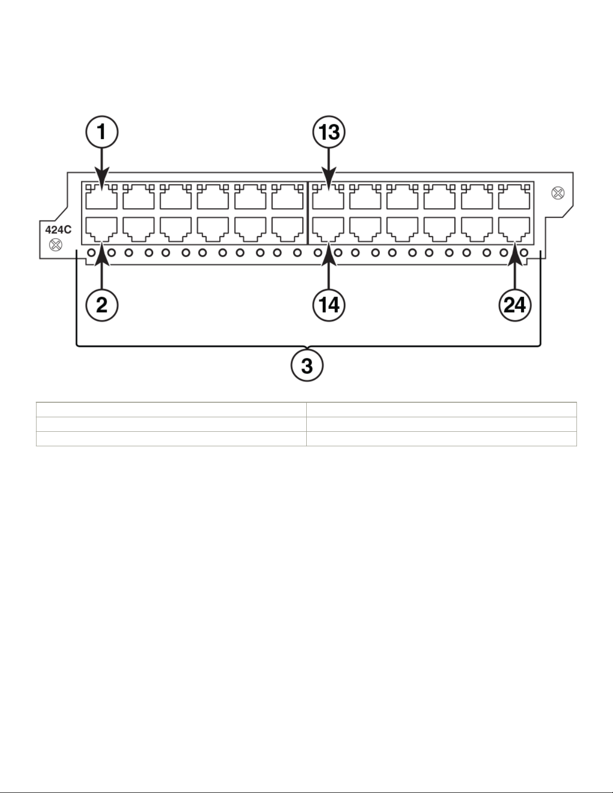
Hardware components
FIGURE 9 Second Generation 24-port Gigabit Ethernet copper module front panel
1. Port 1 13. Port 13
2. Port 2 14. Port 14
3. Location of LEDs 24. Port 24
The front panel includes the following control features:
• 24 10/100/1000 copper ports
• 24 LEDs for port status
• 24 LEDs for PoE status
NOTE
The PoE LEDs work only when PoE is enabled on your device.
LEDs for 24-port copper module
The front panel of the 24-port Gigabit Ethernet copper module includes 24 LEDs (top) that indicate the status of each port, and 24
LEDs (bottom) that indicate the PoE status.
NOTE
The PoE LEDs work only when PoE is enabled on your device.
28 Part Number: 53-1003613-04
Brocade FastIron SX Series Chassis Hardware Installation Guide
Page 29
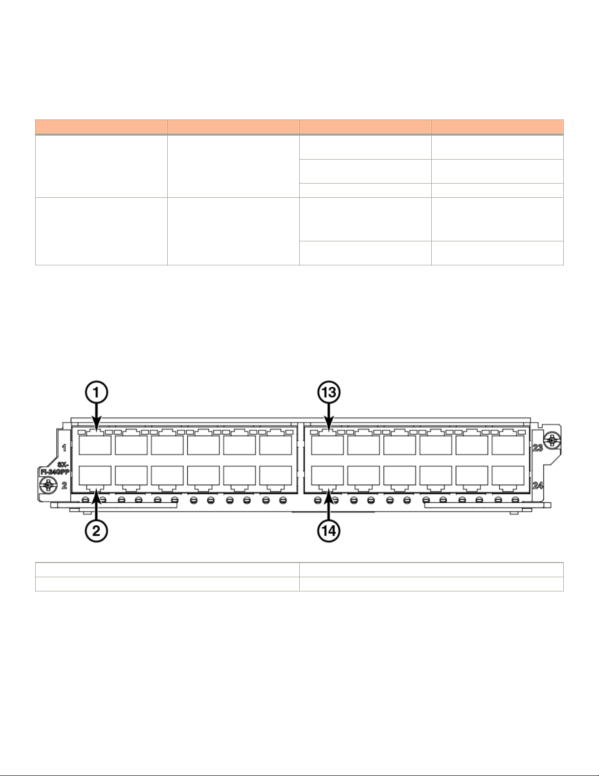
Hardware components
The copper ports provide status information using the LEDs described in the table below.
TABLE 7 LEDs for 10/100/1000 copper ports
LED Position State Meaning
Link or Activity Square LED located at upper left
corner of to port (for top port)
Square LED located at upper right
corner of top port (for bottom port)
PoE (if applicable) Round LED located beneath the
ports. The rst (left-most) LED is
for port 1, the second LED is for
port 2, the third LED is for port 3,
etc.
On (Green) A link is established with the remote
port.
Blinking The port is transmitting and
receiving trac.
O No link exists with the remote port.
On (Green) The port is enabled, a power-
consuming device has been
detected, and the module is
supplying power to the device.
O The port is not providing in-line
power.
Third Generation 24-port Gigabit Ethernet copper module with PoE+
The 24-port Gigabit Ethernet copper interface module with PoE+ supports both IPv4 and IPv6. The gure below shows the front panel
of the IPv4 and IPv6 24-port Gigabit Ethernet copper interface module with PoE+. The module requires Ironware 7.3 or later for
FastIron series.
FIGURE 10 24-port Gigabit Ethernet copper module with PoE+ front panel
1. Port 1 13. Port 13
2. Port 2 14. Port 14
The front panel includes the following control features:
• 24 10/100/1000 copper ports
• 24 LEDs for port status
• 24 LEDs for PoE status
Brocade FastIron SX Series Chassis Hardware Installation Guide
Part Number: 53-1003613-04 29
Page 30

Hardware components
LEDs for 24-port copper module with PoE+
The front panel of the 24-port Gigabit Ethernet copper module includes 24 LEDs (top) that indicate the status of each port, and 24
LEDs (bottom) that indicate the PoE status.
The copper ports provide status information using the LEDs described in the table below.
TABLE 8 LEDs for 10/100/1000 copper ports
LED Position State Meaning
Link or Activity Square LED located at upper left
corner of to port (for top port)
Square LED located at upper right
corner of top port (for bottom port)
PoE or PoE+(if applicable) Round LED located beneath the
ports. The rst (left-most) LED is
for port 1, the second LED is for
port 2, the third LED is for port 3,
etc.
On (Green) A link is established with the remote
port.
Blinking The port is transmitting and
receiving trac.
O No link exists with the remote port.
On (Green) The port is enabled, a power-
consuming device has been
detected, and the module is
supplying power to the device.
O The port is not providing in-line
power.
24-port 100/1000 hybrid ber interface module
The 100/1000 hybrid ber module has 24 ports with connectors for mini-GBIC transceivers (also called Small Form Factor Pluggable
or SFP) Multisource Agreement (MSA)-compliant transceivers. The ports support 100 and 1000 ber mini-GBICs. There are dierent
part numbers available for the second (SX-FI624HF) and third generation (SX-FI-24HF) modules and they cannot be intermixed in
release 08.0.00 and higher.
30 Part Number: 53-1003613-04
Brocade FastIron SX Series Chassis Hardware Installation Guide
Page 31

FIGURE 11 IPv6 100/1000 hybrid ber interface module front panel
Hardware components
1. Port 1 13. Port 13
2. Port 2 24. Port 24
3. Location of LEDs
The front panel contains the following control features:
• 24 Gigabit Ethernet ber ports
• 24 LEDs
The ports on the 24-port 100/1000 Gigabit Ethernet hybrid ber module operate at a xed speed of 100 or 1000 Mbps (they do not
support 10 Mbps connections), and use auto-negotiation to automatically congure the highest performance mode with the connected
device.
The mini-GBIC slots support the 100Base and 1000Base ber cabling listed in Network interfaces on page 34.
Support for 100Base-FX on the 100/1000 interface module
The 24-port 100/1000 ber interface module supports the following types of SFPs for 100Base-FX:
• Multimode SFP - maximum distance is 2 kilometers
• Bidirectional single mode SFP - maximum distance is 10 kilometers
• Long Reach (LR) - maximum distance is 40 kilometers
• Intermediate Reach (IR) - maximum distance is 15 kilometers
To enable support for 100BaseFX, you must enter the CLI command 100-fx at the interface level of the CLI. For CLI command details,
refer to the section "Enabling and Disabling Support for 100BaseFX" in the FastIron Ethernet Switch Administration Guide.
Brocade FastIron SX Series Chassis Hardware Installation Guide
Part Number: 53-1003613-04 31
Page 32

Hardware components
2-port 10-Gigabit Ethernet interface modules
2-port 10-Gigabit Ethernet interface modules have two physical ports, through which you can connect the Brocade device to other
network devices at a speed of 10 Gigabits per second.
The modules have two optical interfaces with LC connectors for 10-Gigabit Small Form Factor Pluggable (SFP+) on the Third
Generation, or XFP on the Second Generation module supporting the applicable MSA-compliant transceivers. On Second Generation 2port 10-Gigabit Ethernet interface modules, the transceivers support 10GBase-SR, 10GBase-LR, and 10GBase-ER ber optic cabling
for LAN PHY. On Third Generation 2-port 10-Gigabit Ethernet interface modules, the transceivers support Twin-ax copper, 10GBaseSR, 10GBase-LR, and 10GBase-ER ber optic cabling for LAN.
FIGURE 12 Second Generation 2-port 10-Gigabit Ethernet interface module front panel
FIGURE 13 Third Generation 2-port 10-Gigabit Ethernet interface module front panel
LEDs for Second Generation 2-port 10-Gigabit Ethernet module
The 10 Gbps ports provide status information using the LEDs listed below.
TABLE 9 LEDs for 10 Gbps ports
LED Position State Meaning
Lnk Top left of connector On Fiber port is connected.
O No ber port connection exists.
Act Bottom left of connector On or Blinking The port is transmitting and
receiving trac.
O The port is not transmitting or
receiving trac.
LEDs for Third Generation 2-Port 10-Gigabit Ethernet module
The 10 Gbps ports provide status information using the LEDs listed below.
32 Part Number: 53-1003613-04
Brocade FastIron SX Series Chassis Hardware Installation Guide
Page 33

Hardware components
TABLE 10 LEDs for 10 Gbps ports
LED Position State Meaning
Link or Activity Triangle-shaped LEDs point either
upwards or downwards towards the
port they indicate
ON (Green) The port is connected, a link is
established with the remote port.
Blinking The port is transmitting or receiving
trac.
OFF The port is not connected, no link
exists with the remote port
Third Generation 8-port 10-Gigabit Ethernet interface modules
Third Generation 8-port 10-Gigabit Ethernet interface modules have eight physical ports, through which you can connect the Brocade
device to other network devices at a speed of 10 Gigabits per second.
The modules have two optical interfaces with LC connectors for 10-Gigabit Small Form Factor Pluggable (SFP+) MSA-compliant
transceivers. The transceivers support 10GBase-SR, 10GBase-LR, and 10GBase-ER ber optic cabling for LAN.
The module requires Ironware 7.3 or later for FastIron series.
4:1 oversubscription
Interface oversubscription is the use of a single physical ingress port to handle incoming trac from multiple devices, and is usually
expressed as a ratio; the ratio shows the proportion of incoming connections to physical ports carry trac to the backplane of the device.
An oversubscribed module allows aggregate bandwidth of user ports exceed the bandwidth of the Network Processor (NP). The SXFI-8XG has two separate NPs. The front-end NP provides basic trac classication and is used as a trac multiplexer. The back-end NP
is a trac aggregator and handles data forwarding.
The SX-FI-8XG module has eight 4:1 oversubscribed ports. Oversubscription is achieved on the SX-FI8-XG by connecting the eight 10
GE external ports to two internal 10GE ports, providing 4:1 oversubscription. The eight 10GE ports on the SX-FI8XG are divided into
two groups of internal physical ports, with ports 1-4 in one group and ports 5-8 in the other group. Each group shares 10GE bandwidth
internally. No CLI command is required to enable oversubscription, but because four external ports are funneling trac into each physical
link, the SX-FI8XG uses virtual interfaces (VEs) to divide each physical link into four logical ports. These VEs can be individually
congured at the interface level.
FIGURE 14 Third Generation 8-port 10-Gigabit Ethernet interface module
The 10 Gbps ports provide status information using the LEDs listed in the table below.
Brocade FastIron SX Series Chassis Hardware Installation Guide
Part Number: 53-1003613-04 33
Page 34

Hardware components
TABLE 11 LEDs for 10 Gbps ports
LED Position State Meaning
Link or Activity Triangle-shaped LEDs point either
upwards or downwards towards the
port it indicates
ON (Green) The port is connected, a link is
established with the remote port.
Blinking The port is transmitting or receiving
trac.
OFF The port is not connected, no link
exists with the remote port
Network interfaces
The table below lists the network interfaces supported on FastIron X Series chassis devices. For network interface and cabling
specications, refer to Cable specications on page 167.
The output of the show media command displays the type of media installed in the ports.
TABLE 12 Network interfaces
Interface Show Media Description
1000Base-BX-D M-GBXD
1000Base-BX-U M-GBXU
1000Base-CWDM Cxxxx (xxx denotes wavelength, for example, C1550
1000Base-LHA M-LHA
1000Base-LHB M-LHB
1000Base-LX M-LX
1000Base-SX M-SX
1000Base-SX2 M-XR or M-SX2
1000Base-T M-C
100Base-BX M-FBXD or M-FBXU
100Base-FX M-FX, M-FXB1, or M-FXB2
100Base-FX-IR M-FX-IR
100Base-FX-LR M-FX-LR
100Base-FX-SR M-FX-SR
100Base-TX (copper only) M-TX
10GBase-1310-MMF 1310-MMF
10GBase-CX4 XG-CX4
10GBase-ER XG-ER
10GBase-LR XG-LR
10GBase-SR XG-SR
34 Part Number: 53-1003613-04
Brocade FastIron SX Series Chassis Hardware Installation Guide
Page 35

Hardware components
Port regions
Ports on FastIron X Series chassis devices are grouped into regions. For a few features, such as port monitoring and unknown unicast
congurations, you will need to know the region to which a port belongs. However, for most features, a port region does not aect
conguration or operation of the feature. If a port region does aect conguration or operation of a feature, it is noted and described in
the appropriate feature section of this guide.
• 48-port 10/100/1000 Mpbs Ethernet PoE interface module (two port regions)
– Ports 1 - 24 belong to port region 0
– Ports 25 - 48 belong to port region 1
• 24-port Gigabit Ethernet copper interface module (two port regions)
– Ports 1 - 12 belong to port region 0
– Ports 13 - 24 belong to port region 1
• 48-port Gigabit Ethernet Copper Interface Module
– Ports 1 - 48
• 24-port Gigabit Ethernet ber interface module (two port regions)
– Ports 1 - 12 belong to port region 0
– Ports 13 - 24 belong to port region 1
• 2-port 10-Gigabit Ethernet ber interface module (two port regions)
– Port 1 belongs to port region 0
– Port 2 belongs to port region 1
• 8-port 10-Gigabit Ethernet interface module (two port regions)
– Ports 1 - 4 belong to port region 0
– Ports 5 - 8 belong to port region 1
Layer 3 routing protocol table sizes
Use the show default values command to display Layer 3 routing protocol table sizes. The command output shows the default,
maximum, and currently
congured values. Refer to the FastIron Ethernet Switch Layer 3 Conguration Guide for sample output.
Power supplies
FastIron X Series chassis devices ship with one or two power supplies, depending on how they are ordered from the factory.
• The FSX 800 comes with one 12-volt AC power supply. You can install up to four power supplies.
• The FSX 1600 comes with two 12-volt AC power supplies. You can install up to eight power supplies; four 12-volt AC or DC
supplies and four 52- 54 volt AC power supplies for PoE and PoE+.
You can use any combination of the supported AC and DC supplies in the same device.
The following information applies to PoE power supplies:
• The SX-ACPWR2500-PoE requires 220-volt input.
• Because the SX-ACPWR2500-PoE powers up to 146 class 3 PoE ports, the SX-ACPWR-PoE is not sucient as a backup
power supply.
Brocade FastIron SX Series Chassis Hardware Installation Guide
Part Number: 53-1003613-04 35
Page 36

Hardware components
TABLE 13 Power supplies supported for the FastIron X Series devices
Sales Model Number Description FSX 800 FSX 1600
SX-ACPWR-SYS 12-volt AC replacement power
supply, manufacturing part number
32014-xxx
12-volt AC original power supply,
manufacturing part number
30351-xxx 2
SX-ACPWR-PoE 52-54 -volt AC replacement power
supply, manufacturing part number
32016-xxx 2
52- 54-volt AC original power
supply, manufacturing part number
30352-xxx 2
SX-DCPWR-SYS 52- 54-volt DC Supported Supported
SX-DCPWR-PoE 52- 54-volt DC Supported Supported
SX-ACPWR2500-PoE 52- 54-volt AC
(220-volt input only)
Supported Supported
Supported Supported
Supported Supported
Supported Supported
Supported Supported
NOTE
For the dierences between replacement and original power supplies, refer to the "Replacement power supplies"
section.
NOTE
Manufacturing part numbers are inscribed on the labels on the top of the power supply.
NOTE
FSX 800 and FSX 1600 devices automatically perform a PoE power upgrade allowing 48-volt power supplies to support a
maximum 54-volts. Refer to the “Dynamic upgrade of PoE power supplies” in the FastIron Ethernet Switch Administration
Guide.
The following power supplies can be installed in the FastIron X Series chassis devices:
• Non-PoE devices:
– The 12-volt AC and DC power supplies (also called system (SYS) power supplies) provide power to one management
module and up to eight non-PoE interface modules. In the FSX 800, you can install a second 12-volt power supply for
redundancy. The FSX 1600 comes with and requires two 12-volt power supplies and supports up to four 12-volt power
supplies for redundancy.
• PoE devices:
NOTE
The Second Generation SX-FI624P modules continue to support only PoE and 802.3af applications. The Third Generation
PoE-compliant devices also support PoE+ and 802.3at applications.
• – The 12-volt AC and DC power supplies (also called system (SYS) power supplies) provide power to the management
module, all non-PoE interface modules (if applicable), and all ports on PoE modules that do not require PoE power or to
which no power-consuming devices are attached. In the FSX 800, you can install a second 12-volt power supply for
redundancy. The FSX 1600 comes with and requires two 12-volt power supplies and supports up to four 12-volt power
supplies for redundancy.
– The 52- 54-volt PoE power supplies provide power to the PoE daughter card, and ultimately to PoE power-consuming
devices. The number of PoE power-consuming devices that one 52- 54-volt power supply can support depends on the
36 Part Number: 53-1003613-04
Brocade FastIron SX Series Chassis Hardware Installation Guide
Page 37

Hardware components
number of watts required by each power-consuming device. Each 52- 54-volt power supply can provide a maximum of
1080 watts of PoE power, and each PoE port supports a maximum of 15.4 watts of power per PoE power-consuming
device. For example, if each PoE power-consuming device attached to the Brocade device consumes 15.4 watts of power,
one 52- 54-volt supply will power up to 70 PoE ports. You can install a second 52-54-volt supply for additional PoE
power.
– The 52- 54-volt (220-volt input only) PoE power supplies provide power to the PoE daughter card, and ultimately to PoE
power-consuming devices. The number of PoE power-consuming devices that one 220-volt power supply can support
depends on the number of watts required by each power-consuming device. Each 220-volt power supply can provide a
maximum of 2260 watts of PoE power, and each PoE port supports a maximum of 15.4 watts of power per PoE powerconsuming device. For example, if each PoE power-consuming device attached to the Brocade device consumes 15.4
watts of power, one 220-volt supply will power up to 146 PoE ports. You can install a second 220-volt supply for
additional PoE power.
NOTE
The system activates as many PoE ports as the 52- 54-volt PoE power supplies can handle. The system calculates the
maximum number of PoE ports it can support based on the number of PoE power supplies installed. PoE ports are enabled
based on their priority settings. The system reserves the maximum congured power per PoE-enabled port, even if the PoE
power-consuming device is drawing less power.
• PoE+ devices (SX-FI48GPP and SX-FI-24GPP):
NOTE
The SX-FI624P module does not support PoE+ and 802.3at applications.
• – The 12-volt AC and DC power supplies (also called system (SYS) power supplies) provide power to the management
module, all non-PoE interface modules (if applicable), and all ports on PoE+ modules that do not require PoE power or to
which no power-consuming devices are attached. In the FSX 800, you can install a second 12-volt power supply for
redundancy. The FSX 1600 comes with and requires two 12-volt power supplies and supports up to four 12-volt power
supplies for redundancy.
– The 52- 54-volt PoE+ power supplies provide power to the PoE+ daughter card, and ultimately to PoE+ power-consuming
devices. The number of PoE+ power-consuming devices that one 52- 54-volt power supply can support depends on the
number of watts required by each power-consuming device. Each 52- 54-volt power supply can provide a maximum of
1080 watts of PoE power, and each PoE+ port supports a maximum of 30 watts of power per PoE+ power-consuming
device. For example, if each PoE+ power-consuming device attached to the Brocade device consumes 30 watts of power,
one 52- 54-volt supply will power up to 36 PoE+ ports. You can install a second 52- 54-volt supply for additional PoE+
power.
– The 52- 54-volt (220-volt input only) PoE+ power supplies provide power to the PoE+ daughter card, and ultimately to
PoE+ power-consuming devices. The number of PoE+ power-consuming devices that one 220-volt power supply can
support depends on the number of watts required by each power-consuming device. Each 220-volt power supply can
provide a maximum of 2260 watts of PoE+ power, and each PoE+ port supports a maximum of 30 watts of power per
PoE+ power-consuming device. For example, if each PoE+ power-consuming device attached to the Brocade device
consumes 30 watts of power, one 220-volt supply will power up to 75 PoE+ ports. You can install a second 220-volt
supply for additional PoE+ power.
NOTE
The system activates as many PoE+ ports as the 52- 54-volt PoE power supplies can handle. The system calculates the
maximum number of PoE+ ports it can support based on the number of PoE+ power supplies installed. PoE+ ports are
enabled based on their priority settings. The system reserves the maximum congured power per PoE+ enabled port, even if
the PoE+ power-consuming device is drawing less power.
Brocade FastIron SX Series Chassis Hardware Installation Guide
Part Number: 53-1003613-04 37
Page 38

Hardware components
CAUTION
The POE power supply is designed exclusively for use with the FastIron X Series POE devices. The power supply produces
extensive power to support 802.3af applications. Installing the power supply in a device other than the FastIron X Series
POE will cause extensive damage to your equipment.
CAUTION
The POE+ power supply is designed exclusively for use with the FastIron X Series POE+ devices. The power supply
produces extensive power to support 802.3at applications. Installing the power supply in a device other than the FastIron X
Series POE+ will cause extensive damage to your equipment.
All power supplies are auto-sensing and auto-switching.
Power supplies are installed in the slots along the bottom of the device.
In FSX 800 devices, the 12-volt (system) power supplies occupy slot numbers 3 and 4 on the right, with the redundant supply in slot 4.
PoE power supplies occupy slot numbers 1 and 2 on the left.
FIGURE 15 Power supply placement in the FSX 800
In the FSX 1600 device, the system power supplies occupy slot numbers 1 - 4 in the top row with the redundant supplies in slot
numbers 3 and 4. The PoE power supplies occupy slot numbers 5 - 8 in the bottom row.
38 Part Number: 53-1003613-04
Brocade FastIron SX Series Chassis Hardware Installation Guide
Page 39

FIGURE 16 Power supply placement in the FSX 1600
Hardware components
Installed power supplies provide power to all device components, sharing the workload equally. If a power supply fails or overheats, the
workload for the failed power supply is redistributed to the redundant power supply, if one is present.
Power supplies are hot swappable, which means you can remove and replace them without powering down the system. You can remove
and insert a power supply without opening the device. If the device contains redundant 12-volt power supplies, you can remove one of
the power supplies without interrupting operation. The remaining power supply provides enough power for all the ports.
CAUTION
Remove the power cord from a power supply before you install it in or remove it from the device. Otherwise, the power
supply or the device could be damaged as a result. (The device can be running while a power supply is being installed or
removed, but the power supply itself should not be connected to a power source.)
Replacement power supplies
Replacement power supplies for the SX-ACPWR-SYS and SX-ACPWR-PoE are functionally equivalent to the original power supplies,
and can be used in combination with the original power supplies in the same device. Although the model numbers for both the newer
and older versions of the power supplies are identical, the front panels and the manufacturing part numbers are
The gure below shows a side-by-side comparison of the SX-ACPWR-SYS replacement power supply and the original power supply.
Brocade FastIron SX Series Chassis Hardware Installation Guide
Part Number: 53-1003613-04 39
dierent.
Page 40

Hardware components
FIGURE 17 SX-ACPWR-SYS replacement and original power supplies
The gure below shows a side-by-side comparison of the SX-ACPWR-PoE replacement power supply and the original power supply.
FIGURE 18 SX-ACPWR-PoE replacement and original power supplies
FIGURE 19 Replacement power supply side view
The latching mechanism on the front of the replacement power supplies dier from the latching mechanism on the original power
supplies. The latching mechanism protrudes slightly in front, making the power supplies slightly longer in depth.
Although the model numbers (SX-ACPWR-SYS and SX-ACPWR-PoE) for the replacement and original power supplies are identical, the
manufacturing part numbers are dierent. The manufacturing part numbers are inscribed on the labels axed to the top of the power
supplies. In addition, the manufacturing part numbers for all installed power supplies are displayed in the output of the show chassis
command.
40 Part Number: 53-1003613-04
Brocade FastIron SX Series Chassis Hardware Installation Guide
Page 41

Hardware components
Power supply LEDs
Each power supply has three LEDs on the faceplate.
TABLE 14 Power supply LEDs
LED Desired State Meaning Abnormal State Meaning or Action
AC OK (AC supply only) ON - Green (steady) The power supply is
receiving AC power from an
AC power source
DC IN (DC supply only) Green (steady) The power supply is
receiving DC power from a
DC power source
DC OUT ON - Green (steady) The power supply is
supplying DC output power
to the device
OFF The power supply is not
receiving power from an AC
power source. You can do
the following:
• Make sure that
the power supply
cord is connected
securely to the
wall outlet and the
power supply.
• Make sure that
the wall outlet is
rated for
115/120V and
20A. If it is not,
obtain a cable
that is compatibly
rated for the
outlet.
• Make sure that
the wall outlet has
power.
OFF The power supply is not
receiving power from a DC
power source. You can do
the following:
• Make sure that
the power supply
cables are
connected
securely to the
power source and
the power supply.
• Make sure that
the DC power
source is 48VDC
@ 37.0 A.
• Make sure that
the power source
has power.
OFF The power supply is not
supplying DC output power
to the device.
If this occurs and the AC
OK (AC power supply) or
DC IN (DC power supply)
LED is Green, then there is
a problem with the power
supply and it must be
replaced.
Brocade FastIron SX Series Chassis Hardware Installation Guide
Part Number: 53-1003613-04 41
Page 42

Hardware components
TABLE 14 Power supply LEDs (continued)
LED Desired State Meaning Abnormal State Meaning or Action
ALM OFF No alarms present and the
power supply is in normal
operating condition.
Amber There is an alarm present
and the power supply is
malfunctioning.
Verify the AC or DC input
and DC output voltages.
About redundant power supplies and power supply failure
A FastIron device with redundant power supplies can maintain full operation when one or more power supplies fail. Power supply failure
can be a failure of the supply itself or the oce power grid connected to the power supply.
A FastIron device can be either 1 + 1 redundant or N + 1 redundant. 1 + 1 redundancy implies that for every power supply, there is
another redundant (backup) power supply. In other words, half of the supplies in the system can fail, and the system will still operate
normally. N + 1 redundancy implies that there is one redundant power supply for N power supplies, where N is a number greater than
one. For example, 3 + 1 redundancy means that in a system with four power supplies, the system will continue to operate normally if one
power supply fails, but will not operate if more than one power supplies fail.
Power consumption is equally distributed (within a certain percentage depending on power load or power supply type) among all power
supplies in the system. When a power supply fails, the power load is redistributed equally among the remaining power supplies. Power
consumption between PoE and system power supplies is not shared, meaning loss of a system power supply does not impact a PoE
power supply, and vice versa.
When one or more system power supplies fail
If one or more system power supplies fail and the system is left with less than the minimum number of power supplies required for
normal operation, the power supplies will go into overload and the system will start to shut down. Several things can happen. The output
voltage of the remaining good power supplies will likely drop as they try unsuccessfully to generate more power than they are capable of.
The system will react to a drop in voltage by increasing the current draw. The hardware will shut down due to over-current protection or
under-voltage protection, whichever takes place rst. One by one, the interface modules will shut down until the power is within the power
budget of the remaining power supplies. There is no particular order in which the interface modules will shut down, as this will occur in
hardware and not in software. The management CPU requires power as well, and may also shut down during a power supply failure.
After a power loss, if the system is left with less than the minimum number of power supplies required for normal operation, the system
will be left in an unknown state. At this point, manual recovery is required (i.e., restore power and power cycle the device).
When one or more PoE power supplies fail
If one or more PoE power supplies fail and the system is left with less than the minimum number of PoE power supplies, the PoE power
supplies will go into overload. Non-PoE functions will not be impacted, provided the System power supplies are still up and running.
Several things can happen with a PoE power supply failure. The output voltage of the remaining good power supplies will likely drop as
they try unsuccessfully to generate more power than they are capable of. The system will react to a drop in voltage by increasing the
current draw. The hardware will shut down PoE function due to over-current protection or under-voltage protection, whichever occurs
rst. The interface modules will start to shut down its PoE ports one by one until the over-power is within the power budget of the
remaining power supplies. There is no particular order in which the PoE ports will shut down, as this occurs in hardware and not in
software.
After a power loss, if the system is left with less than the minimum number of power supplies required for normal operation, the system
will be left in an unknown state. At this point, manual recovery is required (i.e., restore power and power cycle the device).
42 Part Number: 53-1003613-04
Brocade FastIron SX Series Chassis Hardware Installation Guide
Page 43

PoE port density
The table below shows the maximum PoE port density for FastIron X Series chassis devices.
TABLE 15 Maximum number of PoE class 3 (15.4W) ports per power supply
Power Supply Number of Power Supplies FSX 800 FSX 1600
SX-ACPWR-PoE and SX-DCPWRPoE
SX-ACPWR-PoE and SX-DCPWRPoE
SX-ACPWR-PoE and SX-DCPWRPoE
SX-ACPWR-PoE and SX-DCPWRPoE
SX-ACPWR2500-PoE 1 146 140
SX-ACPWR2500-PoE 2 292 280
SX-ACPWR2500-PoE 3 N/A 4381
SX-ACPWR2500-PoE 4 N/A 5841
1 70 70
2 140 140
3 N/A 210
4 N/A 280
Hardware components
PoE+ port density
NOTE
PoE+ is supported on the FI-SX-24-GPP and FI-SX48GPP interface modules for FSX 800 and FSX 1600 devices only.
To determine the maximum number of PoE+ Class (30W) ports available per power supply, use the calculation: One power supply
(1080W) over power consumed by PoE+ port (30W)= 1080W/30W = 36 ports.
The table below shows the maximum PoE+ port density for the FI-SX-24-GPP and FI-SX48GPP interface modules.
TABLE 16 Maximum number of PoE+ class (30W) ports per power supply
Power Supply Number of Power Supplies FSX 800 FSX 1600
SX-ACPWR-PoE and SX-DCPWRPoE
SX-ACPWR-PoE and SX-DCPWRPoE
SX-ACPWR-PoE and SX-DCPWRPoE
SX-ACPWR-PoE and SX-DCPWRPoE
SX-ACPWR2500-PoE 1 75 75
SX-ACPWR2500-PoE 2 150 150
SX-ACPWR2500-PoE 3 N/A 225
SX-ACPWR2500-PoE 4 N/A 300
1 36 36
2 72 72
3 N/A 108
4 N/A 144
Cooling system
The cooling system is contained within the system fan tray assembly and modules. The following components comprise the cooling
system:
• The FSX and FSX 800 each have six four-speed fans.
Brocade FastIron SX Series Chassis Hardware Installation Guide
Part Number: 53-1003613-04 43
Page 44

Hardware components
• The FSX 1600 has two ve-speed fans in the rear of the device.
• One fan control module. The fan control module maintains the power to the fans, and controls the fan speed and the reporting
of the fan status to the management module.
• Two temperature sensors on each management module, and one temperature sensor on each interface module
• One temperature sensor on each switch fabric module.
The fan tray in the FSX and FSX 800 device is located in the right side of the chassis. The FSX 1600 has two fan trays which are located
in the top rear of the chassis.
Upon system startup, the fans operate at low speed, then adjust their speed based on the current temperature of the modules and the
congured temperature thresholds, or by the manually congured fan speed.
By default, the system polls the temperature sensor on each module every 60 seconds to get a temperature reading. For information
about changing the default temperature polling interval, refer to Changing the temperature polling interval on page 103. Depending on
the temperature readings for the modules, the system can do the following:
• Leave the fan speed as is
• Increase the fan speed
• Decrease the fan speed
If the device exceeds the highest temperature threshold or shutdown temperature for ve minutes, the system will shut down the device
to prevent damage
If the temperature of a module exceeds specied high temperature thresholds, the system generates a Syslog message. The system can
also power down the device if the temperature exceeds the highest threshold.
You can change default low and high temperature thresholds for modules and fan speeds. For more information, refer to Changing
temperature thresholds for thermal planes and fan speeds on page 100.
The device ships with all fan components fully installed in the fan tray. For information about replacing the fan tray, refer to one of the
following sections:
• Replacing the FSX 800 fan tray on page 149
• Replacing the FSX 1600 fan assemblies on page 152
Built-in mounting brackets
The front of each FSX and FSX 800 device has built-in mounting brackets that enable you to front-mount the device in a standard 19inch (EIA310-D) rack. For instructions about using the built-in mounting brackets to mount the device in a rack, refer to Installing the
chassis in a rack on page 51.
Alternatively, you can use a rack mount kit (ordered separately) to center-mount the FSX and FSX 800 using two L-shaped mounting
brackets. The rack mount kit comes with instructions for installing the mounting brackets and mounting the device in a rack.
The FSX 1600 does not have built-in mounting brackets. Two brackets ship with the FSX 1600 that enable you to front-mount or
center-mount the device in a rack.
Contact Brocade Communication Systems, Inc for information about rack mount kits.
FSX 1600 slot
The following gure identies the slots where you can install modules and power supplies as well as the electrostatic discharge (ESD)
connector, into which you can plug an ESD wrist strap to ground yourself while handling and installing modules.
44 Part Number: 53-1003613-04
identication
Brocade FastIron SX Series Chassis Hardware Installation Guide
Page 45

DANGER
For safety reasons, the ESD wrist strap should contain a series 1 megaohm resistor.
FIGURE 20 FSX 1600 slots
Hardware components
1. Interface slot 1
2. Interface slot 2
3. Interface slot 3
4. Interface slot 4
5. interface slot 5
6. Interface slot 6
7. Interface slot 7
8. Interface slot 8
9. Interface slot 9
10. Interface slot 10
11. Interface slot 11
Brocade FastIron SX Series Chassis Hardware Installation Guide
Part Number: 53-1003613-04 45
12. Interface slot 12
13. Interface slot 13
14. Interface slot 14
15. Interface slot 15
16. Interface slot 16
17. Management slot 17
18. Management slot 18
19. Switch fabric slot 1
20. Switch fabric slot 2
21. ESD ground connector
Page 46

46 Part Number: 53-1003613-04
Brocade FastIron SX Series Chassis Hardware Installation Guide
Page 47

Installing FastIron SX Devices
• Unpacking the system.....................................................................................................................................................................................47
• Installation precautions....................................................................................................................................................................................48
• Preparing the installation site........................................................................................................................................................................50
• Removing extra shipment screws (FSX 800 only).............................................................................................................................. 50
• Installing the chassis in a rack.......................................................................................................................................................................51
• Removing the slot panels...............................................................................................................................................................................55
• Installing management and interface modules.....................................................................................................................................55
• Attaching a management station................................................................................................................................................................ 62
• Powering on the system................................................................................................................................................................................. 63
• Verifying proper operation............................................................................................................................................................................. 75
This chapter describes how to install your FastIron SX devices.
DANGER
The procedures in this manual are for qualied service personnel.
NOTE
Information about conguring IP addresses and connecting a FastIron SX chassis device to other network devices is covered in
the “Connecting Network Devices and Checking Connectivity” section.
Unpacking the system
FastIron SX devices ship with the following items. Review this list and verify the contents:
NOTE
If any items are missing, contact the place of purchase.
• FastIron SX chassis with the following components installed:
– One or two 12-volt power supplies
– Fan tray assembly or assemblies
– Slot panels installed in all unoccupied slots
– Two switch fabric modules installed
• Rack Mount Kit (FSX 1600 models only)
• Management module or modules (packaged separately)
• Optional interface modules (packaged separately)
• Warranty card
• A 115V AC power cable for each AC power supply you purchase from Brocade
DANGER
If the installation requires a dierent power cord than the one supplied with the device, make sure you use a power cord
displaying the mark of the safety agency that denes the regulations for power cords in your country. The mark is your
assurance that the power cord can be used safely with the device.
Brocade FastIron SX Series Chassis Hardware Installation Guide
Part Number: 53-1003613-04 47
Page 48

Installation precautions
Installation precautions
Follow these precautions when installing the chassis.
General precautions
DANGER
All ber-optic interfaces use Class 1 lasers.
CAUTION
Do not install the device in an environment where the operating ambient temperature might exceed 40°C (104°F).
CAUTION
Make sure the airow around the front, sides, and back of the device is not
restricted.
CAUTION
If you do not install a module or a power supply in a slot, you must keep the slot ller panel in place. If you run the chassis
with an uncovered slot, the system will overheat.
CAUTION
Never leave tools inside the chassis.
Lifting precautions
DANGER
A fully populated chassis is heavy. TWO OR MORE PEOPLE ARE REQUIRED WHEN LIFTING, HANDLING, OR
MOUNTING THESE DEVICES.
DANGER
Mount the devices you install in a rack as low as possible. Place the heaviest device at the bottom and progressively place
lighter devices above.
Power precautions and warnings
NOTE
The power supplies are hot swappable, which means they can be removed and replaced while the chassis is powered on and
running.
CAUTION
Remove the power cord from a power supply before you install it in or remove it from the device. Otherwise, the power
supply or the device could be damaged as a result. (The device can be running while a power supply is being installed or
removed, but the power supply itself should not be connected to a power source.)
DANGER
If the installation requires a dierent power cord than the one supplied with the device, make sure you use a power cord
displaying the mark of the safety agency that denes the regulations for power cords in your country. The mark is your
assurance that the power cord can be used safely with the device.
48 Part Number: 53-1003613-04
Brocade FastIron SX Series Chassis Hardware Installation Guide
Page 49

Installation precautions
DANGER
Make sure to choose the appropriate circuit device depending on the number of AC power supplies installed in the chassis.
The minimum current draw for the system is one AC power supply.
DANGER
Disconnect the power cord from all power sources to completely remove power from the device.
CAUTION
Before plugging a cable into to any port, be sure to discharge the voltage stored on the cable by touching the electrical
contacts to ground surface.
CAUTION
Do not install the device in an environment where the operating ambient temperature might exceed 40°C (104°F).
CAUTION
All devices with DC power supplies are intended for installation in restricted access areas only. A restricted access area is
where access can be gained only by service personnel through the use of a special tool, lock and key, or other means of
security, and is controlled by the authority responsible for the location.
CAUTION
For a DC system, use a grounding wire of at least 6 American Wire Gauge (AWG). The 6 AWG wire should be attached to an
agency-approved crimp connector crimped with the proper tool. The crimp connector should allow for securement to both
ground screws on the enclosure. For the Ground lug, use UL listed Panduit crimp connector, P/N LCD6-10A, and two
10-32, PPH, screws to secure crimp connector to chassis. Grounding position is located on the side of the chassis
adjacent ground symbol.
CAUTION
For the DC input circuit to the system, make sure there is a 30 amp circuit breaker, minimum -48VDC, double pole, on the
input to the terminal block. The input wiring for connection to the product should be copper wire, 8 AWG, marked VW-1,
and rated a minimum of 90 degrees celsius.
CAUTION
All devices with AC power sources are intended for installation in restricted access areas only. A restricted access area is a
location where access can be gained only by service personnel through the use of a special tool, lock and key, or other
means of security.
CAUTION
For a Brocade AC system, use a ground wire of at least 6 American Wire Gauge (AWG). The ground wire should have an
agency-approved crimped connector (provided with the chassis) attached to one end, with the other end attached to
building ground. The connector must be crimped with the proper tool, allowing it to be connected to both ground screws on
the enclosure.
CAUTION
Use a separate branch circuit for each power cord, which provides redundancy in case one of the circuits fails.
CAUTION
The POE power supply is designed exclusively for use with the FastIron X Series POE devices. The power supply produces
extensive power to support 802.3af applications. Installing the power supply in a device other than the FastIron X Series
POE will cause extensive damage to your equipment.
Brocade FastIron SX Series Chassis Hardware Installation Guide
Part Number: 53-1003613-04 49
Page 50

Preparing the installation site
CAUTION
The POE+ power supply is designed exclusively for use with the FastIron X Series POE+ devices. The power supply
produces extensive power to support 802.3at applications. Installing the power supply in a device other than the FastIron X
Series POE+ will cause extensive damage to your equipment.
CAUTION
Ensure that the device does not overload the power circuits, wiring, and over-current protection. To determine the
possibility of overloading the supply circuits, add the ampere (amp) ratings of all devices installed on the same circuit as the
device. Compare this total with the rating limit for the circuit. The maximum ampere ratings are usually printed on the
devices near the input power connectors.
CAUTION
Carefully follow the mechanical guides on each side of the power supply slot and make sure the power supply is properly
inserted in the guides. Never insert the power supply upside down.
CAUTION
Do not attempt to install the power supply without rst releasing the latch on the front of the power supply. Attempting to
install the power supply with a closed latch will result in mechanical damage to the power supply and power supply slot.
DANGER
High Touch Current. Earth connection essential before connecting supply.
Preparing the installation site
Cabling infrastructure
NOTE
Ensure that the proper cabling is installed in the site. For information on cabling, refer to the following sections in this guide:
• Attaching a management station on page 62
• Connecting network devices on page 87
• Cable specications on page 87
Installation location
Before installing the device, plan the location and orientation relative to other devices and equipment. Allow at least three inches of space
at the front of the device for the
back of the device and walls or other obstructions.
ber-optic and power cabling. Also, allow a minimum of three inches of space between the sides and the
Removing extra shipment screws (FSX 800 only)
The FSX 800 ships with two extra screws installed in the right side of the chassis. These screws secure the fan tray, protecting it from
damage during shipment. You must remove these screws before installing the chassis. The
screws.
gure below shows the location of the
To perform this task, you need a #2 Phillips-head screwdriver.
50 Part Number: 53-1003613-04
Brocade FastIron SX Series Chassis Hardware Installation Guide
Page 51

FIGURE 21 Removing the extra screws used for shipment
1. Shipping screws
Installing the chassis in a rack
Installing the chassis in a rack
Because of the weight of a fully loaded chassis (97 lbs minimum), it is recommended that you mount your device in a rack before
installing the modules and power supplies.
In a standard 19-inch (EIA310-D) rack, you can install up to seven FSX 800 devices, or up to three FSX 1600 devices. You can ush-
mount the FSX 800 using the built-in mounting brackets on the front of the device. Alternatively, you can use the optional rack mount kit
to center-mount the chassis in a rack. The FSX 1600 does not have built-in mounting brackets. To mount the FSX 1600 in a rack, you
will need to install the brackets in the rack mount kit that ships with the chassis, see the “Installing mounting brackets on the FSX 1600
chassis” task.
Before performing this task, you should have an assembled rack and a #2 Phillips-head screwdriver.
Keep the following in mind when mounting a chassis in a rack.
DANGER
Make sure the rack housing the device is adequately secured to prevent it from becoming unstable or falling over.
DANGER
Mount the devices you install in a rack as low as possible. Place the heaviest device at the bottom and progressively place
lighter devices above.
DANGER
A fully populated chassis is heavy. TWO OR MORE PEOPLE ARE REQUIRED WHEN LIFTING, HANDLING, OR
MOUNTING THESE DEVICES.
For each FastIron X Series that you install in a rack, you must provide four mounting screws with which to secure the chassis.
To mount the chassis in a rack using the built-in mounting brackets, perform the following tasks.
1. Determine the position of each chassis in the rack.
Brocade FastIron SX Series Chassis Hardware Installation Guide
Part Number: 53-1003613-04 51
Page 52

Installing the chassis in a rack
2. Position two of the four mounting screws for each chassis that you plan to mount in the rack according to the spacings of the
keyhole slots on the brackets. Do not secure the screws completely; leave approximately 1/4 inch of clearance between the
back of the screw head and the rack.
FIGURE 22 Positioning two or four mounting screws in a rack.
1. Keyhole slots
52 Part Number: 53-1003613-04
Brocade FastIron SX Series Chassis Hardware Installation Guide
Page 53

Installing the chassis in a rack
3. Start by mounting the chassis that goes in the lowest position in the rack. With two or more people lifting the chassis, slip the
wide portion of each keyhole slot over the corresponding screw in the rack.
FIGURE 23 Mounting a chassis in a rack - front mount
4. Slide the chassis down so that the screw heads are in the narrow portion of the keyhole slots.
5. Install the remaining two mounting screws through the opposite corners of the brackets into the rack.
6. Tighten all screws to secure the chassis in place.
7. Repeat Step 2 through Step 6 to mount each subsequent chassis in the same rack.
Installing mounting brackets on the FSX 1600 chassis
The FSX 1600 chassis does not ship with mounting brackets installed. You will need to install the brackets, using a #2 Phillips or
athead screwdriver. Mount the brackets as shown in the gure below. Since the brackets are identical, you must rotate one bracket 90
degrees to t on the opposite side from the rst bracket.
Brocade FastIron SX Series Chassis Hardware Installation Guide
Part Number: 53-1003613-04 53
Page 54

Installing the chassis in a rack
FIGURE 24 Installing the mounting brackets on an FSX 1600 chassis.
Repeat Step 2 through Step 6 of the “Installing the chassis in a rack” task to install the FSX 1600 chassis in the rack.
54 Part Number: 53-1003613-04
Brocade FastIron SX Series Chassis Hardware Installation Guide
Page 55

Installing management and interface modules
Removing the slot panels
The chassis ships with a slot panel installed in each empty module slot, ensuring proper airow within the chassis. If you plan to install a
module in a particular slot, you must rst remove the slot panel.
CAUTION
If you do not install a module or a power supply in a slot, you must keep the slot ller panel in place. If you run the chassis
with an uncovered slot, the system will overheat.
Although the slot panels may dier in size, the procedure for removing them is the same. The procedure in this section applies to all
module slot panels.
You need a #2 Phillips-head or athead screwdriver to perform this task.
To remove a slot panel, complete the following tasks.
1. Loosen the screws on either end of the slot panel with a #2 Phillips-head or athead screwdriver.
2. Pull the slot panel out of the chassis and store it in a safe place for future use.
Installing management and interface modules
This section provides the procedures for installing management and interface modules. Although the modules may
function, the procedure for installing them in the chassis is the same. The procedure described in this section applies to all FastIron X
Series devices.
FSX 800 and FSX 1600 management modules are hot swappable, which means you can remove and insert them while the chassis is
powered on and running.
NOTE
Management modules are dedicated, which means you must install them in the appropriate device.
You cannot mix Second Generation and Third Generation 3 modules together in the same chassis.
Because 48-port 10/100/1000 Mbps Ethernet POE+ interface modules (SX-FI48GPP) occupy two vertical half-slots in the FastIron
SX 800 or 1600 device, they can be installed in certain slots only. The table below shows the slot numbers into which you must install
management and interface modules. The following gures show the chassis with slot numbers:
• FSX 800 - FSX 800 chassis on page 15
• FSX 1600 - FSX 1600 chassis on page 17
TABLE 17 Slot numbers for module installation
Module FSX 800 Slot Numbers FSX 1600 Slot Numbers
Management module 9 and 10 9 and 10
Interface modules (except for 48-port POE+) 1 - 8 1 - 8 and 11 - 18
48-port POE+ interface modules (SX-FI48GPP) Module lls 2 slots. Install as follows:
- Install in slot 3, lls slots 1 and 3
- Install in slot 4, lls slots 2 and 4
- Install in slot 7, lls slots 5 and 7
- Install in slot 8, lls slots 6 and 8
Module lls 2 slots. Install as follows:
- Install in slot 1, lls slots 1 and 3
- Install in slot 2, lls slots 2 and 4
- Install in slot 5, lls slots 5 and 7
- Install in slot 6, lls slots 6 and 8
- install in slot 11, lls slots 11 and 13
dier in size and
Brocade FastIron SX Series Chassis Hardware Installation Guide
Part Number: 53-1003613-04 55
Page 56

Installing management and interface modules
TABLE 17 Slot numbers for module installation (continued)
Module FSX 800 Slot Numbers FSX 1600 Slot Numbers
- install in slot 12, lls slots 12 and 14
- install in slot 15, lls slots 15 and 17
- install in slot 16, lls slots 16 and 18
CAUTION
If you do not install a module or a power supply in a slot, you must keep the slot ller panel in place. If you run the chassis
with an uncovered slot, the system will overheat.
Before installing a module in the chassis, have the following on hand:
• A # Phillips-head or athead screwdriver.
• An ESD wrist strap with a plug for connection to the ESD connector on the chassis.
DANGER
For safety reasons, the ESD wrist strap should contain a series 1 megaohm resistor.
To install a module in the chassis, complete the following tasks.
NOTE
You can install management modules in the FSX 800 and FSX 1600 chassis while it is powered on and running.
1. Put on the ESD wrist strap and ground yourself by inserting the plug into the ESD connector located on the chassis front panel.
2. Remove the module from the packaging.
3. Insert the management module or interface module into the appropriate slot and slide the card along the card guide until the
ejector levers rotate towards the module front panel.
NOTE
If you are installing SX-FI48GPP POE+ interface modules, refer to the table above for the slot numbers where these
modules may be installed. Each module occupies the equivalent of two slots, so plan your installation accordingly. See
the fth and sixth gure below.
4. Fold the ejectors towards the center of the module to fully seat the module in the backplane.
56 Part Number: 53-1003613-04
Brocade FastIron SX Series Chassis Hardware Installation Guide
Page 57

Installing management and interface modules
5. Use the #2 Phillips-head or athead screwdriver to tighten the screws on each side of the module faceplate.
The following illustrations show placement of management and interface modules in a FastIron X Series device.
FIGURE 25 Installing a management module in the FSX 800 chassis.
Brocade FastIron SX Series Chassis Hardware Installation Guide
Part Number: 53-1003613-04 57
Page 58

Installing management and interface modules
FIGURE 26 Installing a management module in the FSX 1600 chassis.
58 Part Number: 53-1003613-04
Brocade FastIron SX Series Chassis Hardware Installation Guide
Page 59

FIGURE 27 Installing an interface module in the FSX 800 chassis.
Installing management and interface modules
Brocade FastIron SX Series Chassis Hardware Installation Guide
Part Number: 53-1003613-04 59
Page 60

Installing management and interface modules
FIGURE 28 Installing an interface module in the FSX 1600 chassis.
60 Part Number: 53-1003613-04
Brocade FastIron SX Series Chassis Hardware Installation Guide
Page 61

FIGURE 29 Installing an SX-FI48GPP POE+ interface module in an FSX 800 device
Installing management and interface modules
Brocade FastIron SX Series Chassis Hardware Installation Guide
Part Number: 53-1003613-04 61
Page 62

Attaching a management station
FIGURE 30 Installing an SX-FI48GPP POE+ interface module in an FSX 1600 device
Attaching a management station
You can manage the FastIron X Series system in the following ways:
• Connect a PC or terminal to the serial (Console) port or 10/100/1000 Ethernet port on the management module and access
the system directly or through a Telnet connection to the PC or terminal. See the task below.
• Connect the FastIron X Series switch to your existing management network and manage the switch, along with other network
devices, from a management station. To do this, you can connect a switch to a Gigabit Ethernet port on the management
module. Refer to Attaching a switch to an Ethernet port on page 63.
NOTE
The management network into which you can connect a Gigabit Ethernet port must be separate and isolated from the network
over which user packets are switched and routed.
62 Part Number: 53-1003613-04
Brocade FastIron SX Series Chassis Hardware Installation Guide
Page 63

Powering on the system
Attaching a PC or terminal to the console port or 10/100/1000 copper port
The Console port on the management module has a male DB-9 serial connector, and 10/100/1000 Ethernet copper port or ports
have RJ45 UTP connectors, which allow you to attach a PC or terminal. From the Console port, you can access the system command
line interface (CLI) directly from the PC or terminal or through a Telnet connection. From the Ethernet port, you can access the CLI or
Web Management Interface directly or through a Telnet connection to the PC or terminal.
Before performing this task, you need the following items:
• A PC running a terminal emulation application or a terminal.
• To connect the PC or terminal to the console port (RJ45 serial port) of the device, you need an RJ45 to DB-9 adaptor. For the
pinout information, refer to Console (serial RJ45) management port pinouts on page 165.
• To connect the PC or terminal to a Gigabit Ethernet copper port, you need a category 5 UTP crossover cable, which you must
supply. For information about the port pin assignments, refer to 10/100 and gigabit port pinouts on page 166.
To attach a PC or terminal to the Console port or Gigabit Ethernet copper port, complete the following tasks.
1. Connect a PC or terminal to the Console port or a 10/100/1000 Ethernet port using the appropriate cable.
2. Open the terminal emulation program, and set the session parameters as follows:
• Baud: 9600 bps
• Parity: None
• Data bits: 8
• Stop bits: 1
• Flow control: None
Attaching a switch to an Ethernet port
The 10/100/1000 Ethernet copper ports on the FSX 800 and FSX 1600 management module and the combination Gigabit Ethernet
copper and
management network can then access the Brocade switch using the Brocade Network Advisor.
For more information, see the "Connecting network devices" task.
ber ports on the FSX management module allow you to attach a networking switch. A management station in your existing
Powering on the system
After you complete the hardware installation, you can power on the system. Verify that all modules and power supplies are fully and
properly installed and no module slots are uncovered.
Note the following precautions before powering on the system.
CAUTION
If you do not install a module or a power supply in a slot, you must keep the slot ller panel in place. If you run the chassis
with an uncovered slot, the system will overheat.
DANGER
If the installation requires a dierent power cord than the one supplied with the device, make sure you use a power cord
displaying the mark of the safety agency that denes the regulations for power cords in your country. The mark is your
assurance that the power cord can be used safely with the device.
Brocade FastIron SX Series Chassis Hardware Installation Guide
Part Number: 53-1003613-04 63
Page 64

Powering on the system
NOTE
If the wall outlet is not rated 115 or 120V and 20A, stop and get the appropriate cable for the outlet. Make sure you obtain a
power cord displaying the mark of the safety agency that denes the regulations for power cords in your country. The mark is
your assurance that the power cord can be used safely with the device.
NOTE
The wall outlet should be installed near the equipment and should be easily accessible.
NOTE
The FastIron X Series switch is designed to provide uninterrupted service even when you insert or remove the interface
modules. Therefore, the system does not have a separate on or o power switch. To turn the system o, simply unplug the
power cords.
DANGER
High Touch Current. Earth connection essential before connecting supply.
Power cords
All of the FastIron devices ship with US-compatible power cords unless otherwise
specied at the time of order. United Kingdom- and
European-compatible power cords are also available.
Input connector and plug
In AC deployments, the power cords plug into the rear of the chassis using C20 inputs. The AC power supplies are installed in the front
of the chassis and receive power from the inputs on the back.
In DC deployments, a two-position terminal block is located on the power supply itself, and DC power is wired on the front of the chassis.
TABLE 18 Input connectors for AC and DC power supplies
Power Supplies AC Input Connector Properties
SX-ACPWR-SYS
SX-ACPWR-POE
SX-ACPWR2500-POE
SX-DCPWR-SYS
SX-DCPWR-POE
The gure below shows the power plug conguration for the male and female end of the cable for the SX-ACPWR-SYS and SXACPWR-POE power supplies. The power cord is 2.5 meters in length.
Standard IEC type (IEC320)
C20 type: UL/CSA 20A/250V, VDE 16A/250V
Orientation: Ground pin down
2-position terminal block
The power supply is connected to Earth Ground through the power supply
chassis.
64 Part Number: 53-1003613-04
Brocade FastIron SX Series Chassis Hardware Installation Guide
Page 65

Powering on the system
FIGURE 31 AC power cable male plug and female input connector for SX-ACPWR-SYS and SX-ACPWR-POE power supplies
The gure below shows the power plug for the SX-ACPWR2500-POE power supply.
FIGURE 32 AC power cable plug for SX-ACPWR2500-POE power supply
The gure below shows the DC connector for the SX-DCPWR-SYS and SX-DCPWR-POE power supplies.
Brocade FastIron SX Series Chassis Hardware Installation Guide
Part Number: 53-1003613-04 65
Page 66

Powering on the system
FIGURE 33 DC power cables for SX-DCPWR-SYS and SX-DCPWR-POE power supplies
1. -48 VDC Lead
2. 48 RTN Lead
3. Positive Terminal Screw
4. Negative Terminal Screw
5. AWG Wire
6. Terminal Screw Cover
Power source interruptions
The table below shows how the FastIron chassis protects against power surges and power drops.
66 Part Number: 53-1003613-04
Brocade FastIron SX Series Chassis Hardware Installation Guide
Page 67

Powering on the system
TABLE 19 Chassis power surge and drop protection
Property Protection Mechanism
Power surge MOV and Spark Gap protection
Power drop An AC loss of >15ms will cause the power supply to shut down due to
input under-voltage
Connecting AC power to the chassis
AC power is supplied though an AC power cord that is connected to the back of the chassis. Perform the following tasks to connect AC
power to the chassis.
1. At the rear of the chassis, locate the power receptacles on the power supplies.
2. Lift the cord-retainer and connect a Brocade-supplied AC power cord to the power supply.
Brocade FastIron SX Series Chassis Hardware Installation Guide
Part Number: 53-1003613-04 67
Page 68

Powering on the system
3. Snap the cord-retainer over the power plug to hold it in place.
FIGURE 34 Connecting the AC power cord on an FSX 800 device
1. Cord retainer
68 Part Number: 53-1003613-04
Brocade FastIron SX Series Chassis Hardware Installation Guide
Page 69

FIGURE 35 Connecting the AC power cord on an FSX 1600 device.
Powering on the system
Brocade FastIron SX Series Chassis Hardware Installation Guide
Part Number: 53-1003613-04 69
Page 70

Powering on the system
1. Cord retainer
DANGER
If the installation requires a dierent power cord than the one supplied with the device, make sure you use a
power cord displaying the mark of the safety agency that denes the regulations for power cords in your country.
The mark is your assurance that the power cord can be used safely with the device.
4. Connect the power cord to the wall outlet.
5. Observe the LEDs on the power supply front panel. The AC OK and DC OK LEDs should be green (steady), which indicates the
power supply is providing power to the components. If it is amber or OFF, the power supply is not providing power to the
components. The ALM LED should be OFF.
Connecting DC power to the chassis
You can use a DC power source for the Brocade chassis using a DC-to-DC power supply. DC power must be supplied at 48 V and 30
A.
To perform this task, you need the following items:
• Flathead screwdriver
• Phillips-head screwdriver
• #6 AWG wire (grounding wire)
• #8 AWG wire (input wire)
• Crimping tool
70 Part Number: 53-1003613-04
Brocade FastIron SX Series Chassis Hardware Installation Guide
Page 71

Powering on the system
To connect a DC power source, complete the following tasks.
1. Crimp #6 AWG ground wire and connect it to the ground position on the chassis. The ground position is located on the side or
rear of the chassis next to the ground symbol.
FIGURE 36 Chassis ground on FXS 800 device.
1. Ground
Brocade FastIron SX Series Chassis Hardware Installation Guide
Part Number: 53-1003613-04 71
Page 72

Powering on the system
2. Use a athead screwdriver to remove the two screws holding the transparent cover over the power supply lugs.
FIGURE 37 Power lugs and cover screws
1. Screws holding power lugs 2. Screws holding transparent cover
3. Use a Phillips-head screwdriver to remove the power lugs. Refer to the second gure below.
72 Part Number: 53-1003613-04
Brocade FastIron SX Series Chassis Hardware Installation Guide
Page 73

Powering on the system
4. Crimp #8 AWG input wire into the power lugs and reconnect the lugs to the power supply unit. Refer to the two gures below.
FIGURE 38 Power supply wire
1. #8 AWG power supply wire
This equipment installation must meet NEC/CEC code requirements. Consult local authorities for regulations.
Brocade FastIron SX Series Chassis Hardware Installation Guide
Part Number: 53-1003613-04 73
Page 74

Powering on the system
FIGURE 39 Reconnect lugs to power supply.
1 Ground
2 DC power
5. Re-attach the transparent cover that you removed in Step 1.
6. Connect the positive and negative supply wires to the correct locations on your DC power source, as marked on the power
supply.
7. Observe the LEDs on the power supply front panel. The DC IN and DC OUT LEDs should be green (steady), which indicates
the power supply is providing power to the components. If it is amber or OFF, the power supply is not providing power to the
components. The ALM LED should be OFF.
74 Part Number: 53-1003613-04
Brocade FastIron SX Series Chassis Hardware Installation Guide
Page 75

Verifying proper operation
Verifying proper operation
To verify the proper operation of the chassis after the power is on, you can:
• Observe the LEDs
• Display the module (component) status using the CLI
Observing the LEDs
When the FastIron X Series device is receiving power, you can observe the LEDs to verify that the device initialized successfully. The
table below describes the LEDs, the desired state of each LED, possible abnormal states of each LED, and what to do if an LED
indicates an abnormal state.
TABLE 20 Desired and abnormal LED states after system power-on.
LED Desired State Meaning Abnormal State Meaning or Action
Management module
Active On The module is functioning
as the active management
module.
Pwr On The module is receiving
power.
10/100/1000 Ethernet
Port
On - Green A link is established with the
remote port.
O Neither management
module or is managing the
switch fabric and interface
modules.
A problem may have
occurred during
initialization. Check your PC
or terminal for possible
error messages.
O The module is not receiving
power. You can do the
following:
• Make certain that
the module is
installed properly.
For more
information, refer
to Installing
management and
interface modules
on page 55.
• If using AC power
supplies, refer to
the entry for the
AC power supply
LED in this table
for more
information.
O A link is not established with
the remote port. You can do
the following:
• Verify that the
connection to the
other device has
been properly
made. Also, make
certain that the
other device is
powered on and
Brocade FastIron SX Series Chassis Hardware Installation Guide
Part Number: 53-1003613-04 75
Page 76

Verifying proper operation
TABLE 20 Desired and abnormal LED states after system power-on. (continued)
LED Desired State Meaning Abnormal State Meaning or Action
operating
correctly.
• Try using a
dierent cable.
10/100/1000 Ethernet
Port
SFP+ Port 1 and Port 2 On - Green The SFP+ port is linked. O The SFP+ port is not linked.
SFP+ Port 2 and Port 2 On or blinking The SFP+ port has TX/RX
On or blinking - Yellow The port is transmitting and
receiving packets.
activity.
O for an extended period The port is not transmitting
or receiving packets.
You can check the other
10/100/1000 Ethernet
port LED to make sure a
link is established with the
remote port. If not, take the
actions described in the
Meaning or Action column
for the other
10/100/1000 Ethernet
port LED.
• Verify that the
connection to the
other device has
been properly
made. Also, make
certain that the
other device is
powered on and
operating
correctly.
• Try using a
dierent cable or
optic.
O for an extended period The SFP+ port is not linked.
• Check the Link
LED to make
sure the link is still
established with
the remote port. If
not, take the
actions described
in the Meaning or
Action column for
the Link LED.
• Verify that the
port has not been
disabled through
a conguration
change. You can
use the CLI. If
you have
congured an IP
address on the
device, you also
can use the Web
Management
Interface or
Brocade Network
Advisor.
76 Part Number: 53-1003613-04
Brocade FastIron SX Series Chassis Hardware Installation Guide
Page 77

Verifying proper operation
TABLE 20 Desired and abnormal LED states after system power-on. (continued)
LED Desired State Meaning Abnormal State Meaning or Action
Interface Module
Link or Activity On or blinking A link is established with the
remote port and the port is
transmitting and receiving
user packets.
POE (if applicable) On - Green The port is enabled, a
power-consuming device
has been detected, and the
module is supplying power
to the device.
AC and DC Power Supplies
AC OK (AC supply only) ON - Green (steady) The power supply is
receiving AC power from an
AC power source
DC IN (DC supply only) Green (steady) The power supply is
receiving DC power from a
DC power source
O At this stage of the
installation, you have not yet
cabled the Gigabit Ethernet
ports, so this LED will be
o.
After cabling this port, if this
LED is o, a link is not
established with the remote
port.
O The port is not providing in-
line power.
OFF The power supply is not
receiving power from an AC
power source. You can do
the following:
• Make sure that
the power supply
cord is connected
securely to the
wall outlet and the
power supply.
• Make sure that
the wall outlet is
rated for 115 or
120V and 20A. If
it is not, obtain a
cable that is
compatibly rated
for the outlet.
• Make sure that
the wall outlet has
power.
OFF The power supply is not
receiving power from a DC
power source. You can do
the following:
• Make sure that
the power supply
cables are
connected
securely to the
power source and
the power supply.
• Make sure that
the DC power
source is 48VDC
@ 30 A.
• Make sure that
the power source
has power.
Brocade FastIron SX Series Chassis Hardware Installation Guide
Part Number: 53-1003613-04 77
Page 78

Verifying proper operation
TABLE 20 Desired and abnormal LED states after system power-on. (continued)
LED Desired State Meaning Abnormal State Meaning or Action
DC OUT ON - Green (steady) The power supply is
supplying DC output power
to the chassis
ALM OFF No alarms present and the
power supply is in normal
operating condition.
OFF The power supply is not
supplying DC output power
to the chassis.
If this occurs and the AC
OK (AC power supply) or
DC IN (DC power supply)
LED is Green, then there is
a problem with the power
supply and it must be
replaced.
Amber There is an alarm present
and the power supply is
malfunctioning.
Verify the AC or DC input
and DC output voltages.
If a problem persists after taking action described in this table, contact Brocade’s technical support.
Displaying the module status
After you have attached a PC or terminal to the management module’s Console port or Ethernet port and the Brocade device has
initialized successfully, press Enter to display the following CLI prompt in the terminal emulation window.
FastIron>
If you do not see this prompt, complete the following steps.
1. Make sure the cable is securely connected to your PC or terminal and the Console port or Ethernet port.
78 Part Number: 53-1003613-04
Brocade FastIron SX Series Chassis Hardware Installation Guide
Page 79

Verifying proper operation
2. Check the settings in your terminal emulation program. In addition to the session settings listed in Attaching a PC or terminal to
the console port or 10/100/1000 copper port on page 63, make sure the terminal emulation session is running on the same
serial port you attached to the Console port.
If you view the prompt FastIron> or similar, you are connected to the system and can display the status of the modules using
the CLI. Enter the show module command at any CLI level.
The following shows the output of the show module command when entered on the FSX 800. The display output is similar on
the FSX 1600.
device# show module
Module Status Ports Starting MAC
F1: SX-FISF Switch Fabric active
F2: SX-FISF Switch Fabric active
S1: SX-FI-24GPP 24-port Gig Copper + PoE+ OK 24 0024.3821.7500
S2: SX-FI-8XG 8-port 10G Fiber OK 8 0024.3821.7518
S3: Reserved
S4: SX-FI-8XG 8-port 10G Fiber OK 8 0024.3821.7548
S5: SX-FI-48GPP 48-port Gig Copper + PoE+ OK 48 0024.3821.7500
S6:
S7:
S8:
S9: SX-FIZMRXL6 0-port Management Active 0
{ Status : OK }
S10: Standby 0
Syntax:show module
The Status column shows the module status. The status can be one of the following:
• OK - The module is up and running
• ACTIVE - This applies to the FSX 800 and FSX 1600 management and switch fabric modules only. This indicates that the
module is the active module as opposed to the standby module.
• UNACTIVE -- This status indicates a lost connection, failed initialization, or failed power. Take the module out and reinsert
to continue.
• STANDBY - This applies to the FSX 800 and FSX 1600 management and switch fabric modules only. This indicates that
the module is the standby module as opposed to the active module.
• FAILED - The management module was unable to bring up an interface module properly. If you observe this status, make
certain that the interface module is installed properly. For more information, refer to Installing management and interface
modules on page 55.
• DISABLED - The module is not up and running.
Brocade FastIron SX Series Chassis Hardware Installation Guide
Part Number: 53-1003613-04 79
Page 80

80 Part Number: 53-1003613-04
Brocade FastIron SX Series Chassis Hardware Installation Guide
Page 81

Connecting Network Devices and Checking Connectivity
• Overview................................................................................................................................................................................................................81
• Assigning permanent passwords................................................................................................................................................................81
• Conguring IP addresses...............................................................................................................................................................................83
• Connecting network devices.........................................................................................................................................................................87
• Testing network connectivity.........................................................................................................................................................................92
• Troubleshooting network connections......................................................................................................................................................93
Overview
This chapter provides the details for connecting network devices and checking network connectivity.
DANGER
The procedures in this manual are for qualied service personnel.
The table below lists the tasks you must perform to connect your Brocade device, and how to troubleshoot any problems that can arise.
TABLE 21 Network connectivity tasks
Step Task Page
1 Secure access to the CLI by assigning
passwords.
2 Congure IP addresses for the management,
Ethernet, virtual, and loopback interfaces.
3 Connect your device to another networking
device.
4 Observe certain LEDs to determine if the
network connections are functioning properly.
Also test a port for connectivity to other
networking devices using the ping and
traceroute commands.
5 Troubleshoot any problems that can arise. Troubleshooting network connections on page
Assigning permanent passwords on page 81
Conguring IP addresses on page 83
Connecting network devices on page 87
Testing network connectivity on page 92
93
Assigning permanent passwords
By default, the CLI is not protected by passwords. To secure CLI access, It is strongly recommended that you assign passwords.
NOTE
You can assign passwords using the Brocade Network Advisor software if an enable password for a Super User has been
congured on the device.
The CLI contains the following access levels:
• User EXEC - The level you enter when you rst start a CLI session. At this level, you can view some system information but you
cannot congure system or port parameters.
Brocade FastIron SX Series Chassis Hardware Installation Guide
Part Number: 53-1003613-04 81
Page 82

Assigning permanent passwords
• Privileged EXEC - This level is also called the Enable level and can be secured by a password. You can perform tasks such as
manage les on the ash module, save the system conguration to ash, and clear caches at this level.
• CONFIG - The conguration level. This level lets you congure the system’s IP address and congure switching and routing
features. To access the CONFIG mode, you must already be logged into the Privileged level of the EXEC mode.
You can set the following levels of Enable passwords:
• Super User - Allows complete read and write access to the system. This is generally for system administrators and is the only
password level that allows you to congure passwords.
NOTE
You must set a super user password before you can set other types of passwords.
• Port Conguration - Allows read and write access for specic ports but not for global (system-wide) parameters.
• Read Only - Allows access to the Privileged EXEC mode and CONFIG mode but only with read access.
To set passwords, complete the following steps.
1. At the opening CLI prompt, enter the following command to change to the Privileged level of the EXEC mode.
device> enable
2. Access the CONFIG level of the CLI by entering the following command.
device#
device(cong#
congure terminal
3. Enter the following command to set the super-user password.
device(cong)# enable super-user-password text
NOTE
You must set the super-user password before you can set other types of passwords.
4. Enter the following commands to set the port conguration and read-only passwords.
device(cong)# enable port-cong-password text
device(cong)# enable read-only-password text
If you forget your super-user password, refer to Recovering from a lost password on page 82.
Syntax: enable{ enable super-user-password text | read-only-password text | port-cong-password text }
Password text can be up to 32 characters long.
Recovering from a lost password
By default, the CLI does not require passwords. However, if someone has congured a password for the device but the password has
been lost, you can regain super-user access to the device using the following procedure.
NOTE
Recovery from a lost password requires direct access to the serial port and a system reset.
To recover from a lost password, complete the following steps.
1. Start a CLI session over the serial interface to the Brocade device.
2. Reboot the device.
3. While the system is booting, before the initial system prompt appears, enter b to enter the boot monitor mode.
82 Part Number: 53-1003613-04
Brocade FastIron SX Series Chassis Hardware Installation Guide
Page 83

Conguring IP addresses
4. Enter no password at the prompt. (You cannot abbreviate this command.)
5. Enter boot system ash primary at the prompt. This command causes the device to bypass the system password check.
6. After the console prompt reappears, assign a new password.
Conguring IP addresses
You must congure at least one IP address using the serial connection to the CLI before you can manage the system using the other
management interfaces. In addition, Brocade routers require an IP subnet address for the subnet in which you plan to place them in your
network.
IPv4 devices
Brocade IPv4 devices support both classical IP network masks (Class A, B, and C subnet masks, and so on) and Classless Interdomain
Routing (CIDR) network prex masks:
• To enter a classical network mask, enter the mask in IP address format. For example, enter "10.x.x.x 255.255.255.0" for an IP
address with a Class-C subnet mask.
• To enter a prex number for a network mask, enter a forward slash ( / ) and the number of bits in the mask immediately after the
IP address. For example, enter "10.x.x.x/24" for an IP address that has a network mask with 24
signicant ("mask") bits.
By default, the CLI displays network masks in classical IP address format (example: 255.255.255.0). You can change the display to the
prex format. Refer to the FastIron Ethernet Switch Layer 3 Conguration Guide for more information.
Conguring IPv4 management interface while running Layer 3 software
Before attaching equipment to a Brocade router, you must assign an interface IP address to the subnet on which the router will be
located. You must use the serial connection to assign the rst IP address. For subsequent addresses, you also can use the CLI through
Telnet.
By default, you can congure up to 24 IP interfaces on each port, virtual interface, and loopback interface. You can increase this amount
to up to 64 IP subnet addresses per port by increasing the size of the subnet-per-interface table. Refer to the FastIron Conguration
Guide for more information.
The following procedure shows how to add an IPv4 address and mask to a router port.
1. At the opening CLI prompt, enter enable .
device> enable
2. Enter the following command at the CLI Privileged EXEC level prompt, then press Enter . This command erases the factory test
conguration if still present.
device# erase startup-config
CAUTION
Use the erase startup-cong command only for new systems. If you enter this command on a system you have
already congured, the command erases the conguration. If you accidentally do erase the conguration on a
congured system, enter the write memory command to save the running conguration to the startup-cong le.
Brocade FastIron SX Series Chassis Hardware Installation Guide
Part Number: 53-1003613-04 83
Page 84

Conguring IP addresses
3. Access the conguration level of the CLI by entering the following command.
Privileged EXEC Level.
device# configure terminal
Global CONFIG Level.
device(config)#
Congure the IPv4 address and mask address for the interface.
4.
device(config)# int e 1/5
device(config)# ip address 10.x.x.x 255.255.255.0
NOTE
You can use the syntaxip address ip-addr/mask-bits if you know the subnet mask length. In the above example, you
could enter ip address 10.x.x.x/24 .
Syntax: enable [password]
Syntax: congure terminal
Syntax: [no] ip address ip-addr ip-mask [ secondary ]
or
Syntax: [no] ip address ip-addr/mask-bits [ secondary ]
Use the secondary parameter if you have already congured an IP address within the same subnet on the interface.
Conguring IPv4 management interface while running Layer 2 software
congure an IPv4 address to a device running Layer 2 software, complete the following tasks.
To
1. At the opening CLI prompt, enter enable .
device> enable
2. Enter the following command at the Privileged EXEC level prompt (for example, device# ), then press Enter . This command
erases the factory test conguration if still present.
device# erase startup-config
CAUTION
Use the erase startup-cong command only for new systems. If you enter this command on a system you have
already congured, the command erases the conguration. If you accidentally do erase the conguration on a
congured system, enter the write memory command to save the running conguration to the startup-cong le.
3. Access the conguration level of the CLI by entering the following command.
Privileged EXEC Level.
device# configure terminal
Global CONFIG Level.
device(config)#
84 Part Number: 53-1003613-04
Brocade FastIron SX Series Chassis Hardware Installation Guide
Page 85

4. Congure the IPv4 address and mask for the switch.
device(config)# ip address 10.x.x.x 255.255.255.0
5. Set a default gateway address for the switch.
device(config)# ip default-gateway 10.x.x.x
NOTE
You do not need to assign a default gateway address for single subnet networks.
Syntax: enable [ password ]
Syntax: congure terminal
Syntax:[no] ip address ip-addr ip-mask
or
Syntax: [no] ip address ip-addr/ip-mask
Syntax: ip default-gateway ip-addr
Conguring IP addresses
IPv6 devices
Brocade IPv6 devices support the 128-bit addressing format, composed of 8 elds of 16-bit hexadecimal values separated by colons
(:). For example, 2001:DB8:0000:0200:002D:D0FF:FE48:4672 is an IPv6 address, which can also be expressed as
2001:DB8:0:200:2D:D0FF:FE48:4672 after omitting the leading zeros.
Conguring IPv6 management interface while running Layer 3 software
Before attaching equipment to a Brocade router, you must assign an interface IP address to the subnet on which the router will be
located. You must use the serial connection to assign the
Telnet or the Web Management Interface.
By default, you can congure up to 24 IP interfaces on each port, virtual interface, and loopback interface. You can increase this amount
to up to 64 IP subnet addresses per port by increasing the size of the subnet-per-interface table. Refer to the FastIron Conguration
Guide for more information.
The following procedure shows how to add an IPv6 address and mask to a router port.
1. At the opening CLI prompt, enter enable.
device# enable
2. Enter the following command at the CLI Privileged EXEC level prompt, then press Enter . This command erases the factory test
conguration if still present.
device# erase startup-config
rst IP address. For subsequent addresses, you also can use the CLI through
CAUTION
Use the erase startup-cong command only for new systems. If you enter this command on a system you have
already congured, the command erases the conguration. If you accidentally do erase the conguration on a
congured system, enter the write memory command to save the running conguration to the startup-cong le.
Brocade FastIron SX Series Chassis Hardware Installation Guide
Part Number: 53-1003613-04 85
Page 86

Conguring IP addresses
3. Access the conguration level of the CLI by entering the following command.
Privileged EXEC Level
device# configure terminal
Global CONFIG Level
device(config)#
Congure the IPv6 address and mask address for the interface.
4.
device(config)# int e 1/5
device(config)# ipv6 address 2001:DB8:12D:1300:240:D0FF:FE48:4672:/64
These commands congure the global prex 2001:DB8:12d:1300:/64 and the interface ID::240:D0FF:FE48:4672, and
enable IPv6 on interface e 1/5.
NOTE
The above procedure shows how to congure an IPv6 address with a manually congured Interface ID as the address
for the interface. You could also congure an IPv6 address with an automatically computed EUI-64 Interface ID as the
address for the interface. Link-local IPv6 addresses are also supported. For details, refer to the FastIron Conguration
Guide.
Syntax: enable password
Syntax:
congure terminal
Syntax:[no] ipv6address ipv6-prex/prex-length
You must specify the ipv6-prex parameter in hexadecimal using 16-bit values between colons as documented in RFC 2373.
You must specify the prex-length parameter in decimal value. A slash mark (/) must follow the ipv6-prex parameter and
precede the prex-length parameter.
Conguring IPv6 management interface while running Layer 2 software
congure an IPv6 address to a device running Layer 2 software, complete the following tasks.
To
1. At the opening CLI prompt, enter enable .
device> enable
2. Enter the following command at the Privileged EXEC level prompt (for example, FastIron# ), then press Enter. This command
erases the factory test conguration if still present.
device# erase startup-config
CAUTION
Use the erase startup-cong command only for new systems. If you enter this command on a system you have
already congured, the command erases the conguration. If you accidentally do erase the conguration on a
congured system, enter the write memory command to save the running conguration to the startup-cong le.
86 Part Number: 53-1003613-04
Brocade FastIron SX Series Chassis Hardware Installation Guide
Page 87

3. Access the conguration level of the CLI by entering the following command.
Privileged EXEC Level.
device# configure terminal
Global CONFIG Level.
device(config)#
Congure the IP address and mask for the switch.
4.
device(config)# ipv6 address 2001:DB8:12D:1300:240:D0FF:FE48:4000:1/64
NOTE
The above procedure shows how to congure an IPv6 address with a manually congured interface ID as the systemwide address for the switch. You could also congure an IPv6 address with an automatically computed EUI-64
interface ID as the system-wide address for the switch. A link-local IPv6 address is also supported. For details, refer to
the FastIron Ethernet Switch Layer 3 Conguration Guide.
Syntax: enable password
Syntax: congure terminal
Connecting network devices
Syntax: [no] ipv6address ipv6-prex/prex-length
You must specify the ipv6-prex variable in hexadecimal using 16-bit values between colons as documented in RFC 2373.
You must specify the prex-length variable in decimal value. A slash mark (/) must follow the ipv6-prex variable and precede
the prex-length variable.
Connecting network devices
Brocade devices support connections to other vendors’ routers, switches, and hubs, as well as other Brocade devices.
Cable
Refer to Cable specications on page 167 for cable lengths and types.
Connecting to Ethernet or fast Ethernet hubs
For copper connections to Ethernet hubs, a 10/100Base-TX or 1000Base-T switch, or another Brocade device, a crossover cable is
required (see UTP and Cat-5 crossover cable diagrams below). If the hub is equipped with an uplink port, it will require a straight-through
cable instead of a crossover cable.
specications
NOTE
The 802.3ab standard (automatic MDI or MDIX detection) calls for automatic negotiation of the connection between two
1000Base-T ports. Therefore, a crossover cable may not be required; a straight-through cable may work as well. For more
information about this feature, refer to the FastIron Ethernet Switch Administration Conguration Guide.
Brocade FastIron SX Series Chassis Hardware Installation Guide
Part Number: 53-1003613-04 87
Page 88

Connecting network devices
FIGURE 40 UTP crossover cable
FIGURE 41 Cat-5 crossover cable for 1000Base-T
NOTE
The 802.3ab standard calls for automatic negotiation of the connection between two 1000Base-T ports. Consequently, a
crossover cable may not be required; a straight-through cable may work as well.
Connecting to workstations, servers, or routers
Straight-through UTP cabling is required for direct UTP attachment to workstations, servers, or routers using network interface cards
(NICs).
Fiber cabling with LC connectors is required for direct attachment to Gigabit NICs or switches and routers.
88 Part Number: 53-1003613-04
Brocade FastIron SX Series Chassis Hardware Installation Guide
Page 89

Connecting network devices
NOTE
The 802.3ab standard (automatic MDI or MDIX detection) calls for automatic negotiation of the connection between two
1000Base-T ports. Therefore, a crossover cable may not be required; a straight-through cable may work as well. For more
information about this feature, refer to the FastIron Ethernet Switch Administration Conguration Guide.
Connecting a network device to a ber port on the Brocade device
For direct attachment from the Brocade device to a Gigabit NIC, switch, or router,
NOTE
All physical IP interfaces on FastIron X Series Layer 3 devices share the same MAC address. For this reason, if more than one
connection is made between two devices, one of which is a FastIron X Series Layer 3 device, Brocade recommends the use of
virtual interfaces. It is not recommended to connect two or more physical IP interfaces between two routers.
To connect a Brocade device to another network device using a ber port, you must do the following:
• Install a ber optic module (SFP transceiver or mini-GBIC for Gigabit Ethernet ports, or XFP-MSA or SFP+ MSA transceiver for
10-Gigabit Ethernet ports)
• Cable the ber optic module
The following sections provide information about performing these tasks.
Installing a
You must install a ber optic module in each Gigabit Ethernet and 10-Gigabit Ethernet ber port you want to use.
ber optic module
DANGER
All ber-optic interfaces use Class 1 lasers.
NOTE
Refer to the “Installation precautions” section for other hardware installation precautions.
NOTE
Some older SFP modules (mini-GBICs for Gigabit Ethernet ports) have latching mechanisms which are larger than the newer
parts. These latches could interfere with one another when inserted side-by-side into a module. Avoid using these mini-GBICs
side-by-side in the same module. These modules are identied by the numbers PL-XPL-00-S13-22 or PL-XPL-00-L13-23
above the serial number. Newer mini-GBICs do not have this limitation.
ber cabling with an LC connector is required.
Before installing a ber optic module, have the following on hand:
• An ESD wrist strap with a plug for connection to the ESD connector on the chassis.
DANGER
For safety reasons, the ESD wrist strap should contain a series 1 megaohm resistor.
To install a ber optic module into a Gigabit Ethernet or 10-Gigabit Ethernet port, complete the following tasks.
1. Put on the ESD wrist strap and ground yourself by inserting the plug into the ESD connector located in the lower right corner of
the chassis front.
2. Remove the module from the protective packaging.
3. If necessary, remove the metal cover from the port on the interface module control panel.
Brocade FastIron SX Series Chassis Hardware Installation Guide
Part Number: 53-1003613-04 89
Page 90

Connecting network devices
4. Insert the ber-optic module into the port until the module clicks into place. Fiber-optic modules are keyed to prevent incorrect
insertion.
Cabling a ber optic module
To cable a ber-optic module, complete the following tasks.
1. Remove the protective covering from the ber optic module and store it for future use.
2. Before cabling a ber optic module, it is strongly recommended that you clean the cable connectors and the port connectors.
Refer to Cleaning ber optic modules on page 90.
3. Insert the cable connector (a tab on each connector should face up) into the port connector or until the tab locks into place.
Cleaning
To avoid problems with connections between ber optic modules (SFP (mini-GBIC), SFP+, or XFP) and the ber cable connectors, it is
strongly recommended that you clean both connectors each time you disconnect and reconnect them. Refer to Cleaning the ber optic
connectors on page 119.
ber optic modules
Automatic MDI or MDIX detection
All 10/100 and Gigabit Ethernet copper ports on FastIron devices support automatic Media Dependent Interface (MDI) and Media
Dependent Interface Crossover (MDIX) detection. This feature is enabled on all 10/100 and Gigabit copper ports by default. For each
port, you can disable auto MDI or MDIX, or designate the port as an MDI port, or an MDIX port.
For more information about this feature refer to the FastIron Ethernet Switch Administration Conguration Guide.
Using a CX4 transceiver
A twin-axial 10G copper CX4 XFP transceiver can be installed in any 10G port. For a link to operate properly, both sides must use
identical CX4 transceivers. See the rst gure below.
The CX4 transceiver requires a 15 meter CX4-grade cable with 24 or 26 American Wire Gauge (AWG). This cable can be purchased
from Brocade. Refer to part number CAB-CX4-0050 when ordering. See the second gure below.
NOTE
The CX4 transceiver is not hot-swappable.
90 Part Number: 53-1003613-04
Brocade FastIron SX Series Chassis Hardware Installation Guide
Page 91

FIGURE 42 CX4 transceiver
1. CX4 transceiver
Connecting network devices
FIGURE 43 CX4 transceiver cable
1 CX4 transceiver cable
Brocade FastIron SX Series Chassis Hardware Installation Guide
Part Number: 53-1003613-04 91
Page 92

Testing network connectivity
Testing network connectivity
After you install the network cables, you can test network connectivity to other devices by pinging those devices. You also can observe
the LEDs related to network connection and perform trace routes.
For more information about ping and traceroute commands, refer to the FastIron Ethernet Switch Layer 3 Conguration Guide.
Observing LEDs
After you install the network cables, you can observe certain LEDs to determine if the network connections are functioning properly. The
table below outlines the LEDs related to the network connections, the desired state of each LED, possible abnormal states of each LED,
and what to do if an LED indicates an abnormal state.
NOTE
Some modules use combined link and activity LEDs.
TABLE 22 Network connection-related LED states
LED Desired State Meaning Abnormal State Meaning or Action
Link On (Green) A link is established with the
remote port.
O No link exists with the
remote port. You can do the
following:
• Verify that the
connection to the
other network
device has been
properly made.
Also, make
certain that the
other network
device is powered
on and operating
correctly.
• Verify that the
transmit port on
the Brocade
device is
connected to the
receive port on
the other network
device, and that
the receive port
on the Brocade
device is
connected to the
transmit port on
the other network
device. If you are
not certain,
remove the two
cable connectors
from the port
connector and
reinsert them in
the port
connector,
reversing their
order.
92 Part Number: 53-1003613-04
Brocade FastIron SX Series Chassis Hardware Installation Guide
Page 93

Troubleshooting network connections
TABLE 22 Network connection-related LED states (continued)
LED Desired State Meaning Abnormal State Meaning or Action
• Dust may have
accumulated in
the cable
connector or port
connector. For
information about
cleaning the
connectors, refer
to Cleaning ber
optic modules on
page 90.
• If the other
actions do not
resolve the
problem, try
using a dierent
port or a dierent
cable.
Active On or blinking (Yellow) The port is transmitting and
receiving user packets.
O for an extended period. The port is not transmitting
or receiving user packets.
You can do the following:
• Check the Link
LED to make
sure the link is still
established with
the remote port. If
not, take the
actions described
in the Meaning or
Action column for
the Link LED.
• Verify that the
port has not been
disabled through
a conguration
change. You can
use the CLI. If
you have
congured an IP
address on the
device, you also
can use the Web
Management
Interface or
Brocade Network
Advisor.
If a problem persists after taking these actions, contact Brocade technical support.
Troubleshooting network connections
To resolve problems that may arise with network connections:
• For the indicated port, verify that both ends of the cabling (at the Brocade device and the connected device) are snug.
Brocade FastIron SX Series Chassis Hardware Installation Guide
Part Number: 53-1003613-04 93
Page 94

Troubleshooting network connections
• Verify that the Brocade device and the connected device are both powered on and operating correctly.
• Verify that the port has not been disabled by a conguration change. You can use the CLI. If you have congured an IP address
on the device, you also can use Brocade Network Advisor.
• Verify that you have used the correct cable type for the connection:
– For twisted-pair connections to an end node, use straight-through cabling.
– For ber-optic connections, verify that the transmit port on the device is connected to the receive port on the connected
device, and that the receive port on device is connected to the transmit port on the connected device.
• For copper ports, you can test the cable using Virtual Cable Testing. For more information, refer to the chapter Hardware
Component Monitoring in the FastIron Ethernet Switch Administration Conguration Guide.
• If the other procedures do not resolve the problem, try using a dierent port or a dierent cable.
Support for digital optical monitoring
You can
feature is enabled, the system monitors the temperature and signal power levels for the optical transceivers in the specied ports.
Console messages and syslog messages are sent when optical operating conditions fall below or rise above the XFP or SFP
manufacturer’s recommended thresholds. For details about this feature and how to congure it, refer to the FastIron Ethernet Switch
Administration Conguration Guide.
congure your Brocade device to monitor optical transceivers in the system, either globally or by specied ports. When this
94 Part Number: 53-1003613-04
Brocade FastIron SX Series Chassis Hardware Installation Guide
Page 95

Managing the Chassis and Modules
• Overview................................................................................................................................................................................................................95
• Displaying chassis status and temperature readings..........................................................................................................................95
• Managing the cooling system...................................................................................................................................................................... 99
• Displaying the Syslog conguration and static and dynamic buers....................................................................................... 105
• Syslog messages for PCI (hardware) errors........................................................................................................................................ 106
• Managing the switch fabric modules (FSX 800 and FSX 1600 only).................................................................................... 107
• Displaying management module CPU usage....................................................................................................................................107
• Removing MAC address entries.............................................................................................................................................................. 107
Overview
This chapter contains information about rening the conguration of, monitoring, and managing the hardware components.
Displaying chassis status and temperature readings
You can display the following information about your Brocade device:
• Status of the power supplies
• Status of the fans
• Temperature readings and thresholds of the management and interface modules
• Temperature readings and thresholds of the switch fabric modules (FSX 800 and FSX 1600 only)
• The MAC address of the chassis
The following shows an example of the show chassis command output on the FSX 800.
device# show chassis
Chassis Type: FastIron SX 800
Power supply 1 not present
Power supply 2 not present
Power supply 3 (H1250C - AC - Regular) present, status ok
Power supply 4 not present
Fan 1 ok, speed (auto): 1<->