


Page 1

®
DRAFT: BROCADE CONFIDENTIAL
53-1002187-01
18 February 2011
Brocade FastIron LS and
LS-STK
Hardware Installation Guide
Supporting Release 07.2.02
Page 2

DRAFT: BROCADE CONFIDENTIAL
Copyright © 2011 Brocade Communications Systems, Inc. All Rights Reserved.
Brocade, the B-wing symbol, BigIron, DCX, Fabric OS, FastIron, IronPoint, IronShield, IronView, IronWare, JetCore, NetIron,
SecureIron, ServerIron, StorageX, and TurboIron are registered trademarks, and DCFM, Extraordinary Networks, and SAN Health
are trademarks of Brocade Communications Systems, Inc., in the United States and/or in other countries. All other brands,
products, or service names are or may be trademarks or service marks of, and are used to identify, products or services of their
respective owners.
Notice: This document is for informational purposes only and does not set forth any warranty, expressed or implied, concerning
any equipment, equipment feature, or service offered or to be offered by Brocade. Brocade reserves the right to make changes to
this document at any time, without notice, and assumes no responsibility for its use. This informational document describes
features that may not be currently available. Contact a Brocade sales office for information on feature and product availability.
Export of technical data contained in this document may require an export license from the United States government.
The authors and Brocade Communications Systems, Inc. shall have no liability or responsibility to any person or entity with
respect to any loss, cost, liability, or damages arising from the information contained in this book or the computer programs that
accompany it.
The product described by this document may contain “open source” software covered by the GNU General Public License or other
open source license agreements. To find-out which open source software is included in Brocade products, view the licensing
terms applicable to the open source software, and obtain a copy of the programming source code, please visit
http://www.brocade.com/support/oscd.
Brocade Communications Systems, Incorporated
Corporate and Latin American Headquarters
Brocade Communications Systems, Inc.
130 Holger Way,
San Jose, CA 95134
Tel: 1-408-333-8000
Fax: 1-408-333-8101
E-mail: info@brocade.com
European Headquarters
Brocade Communications Switzerland Sàrl
Centre Swissair
Tour B - 4ème étage
29, Route de l'Aéroport
Case Postale 105
CH-1215 Genève 15
Switzerland
Tel: +41 22 799 5640
Fax: +41 22 799 5641
E-mail: emea-info@brocade.com
Asia-Pacific Headquarters
Brocade Communications Systems China HK, Ltd.
No. 1 Guanghua Road
Chao Yang District
Units 2718 and 2818
Beijing 100020, China
Tel: +8610 6588 8888
Fax: +8610 6588 9999
E-mail: china-info@brocade.com
Asia-Pacific Headquarters
Brocade Communications Systems Co., Ltd. (Shenzhen WFOE)
Citic Plaza
No. 233 Tian He Road North
Unit 1308 – 13th Floor
Guangzhou, China
Tel: +8620 3891 2000
Fax: +8620 3891 2111
E-mail: china-info@brocade.com
Document History
Title Publication number Summary of changes Date
Brocade FastIron LS and LS-STK
Hardware Installation Guide
53-1002187-01 New document February 2011
Page 3

Contents
DRAFT: BROCADE CONFIDENTIAL
About This Document
Audience . . . . . . . . . . . . . . . . . . . . . . . . . . . . . . . . . . . . . . . . . . . . . . . vii
Supported hardware and software . . . . . . . . . . . . . . . . . . . . . . . . . . vii
Document conventions. . . . . . . . . . . . . . . . . . . . . . . . . . . . . . . . . . . . vii
Text formatting . . . . . . . . . . . . . . . . . . . . . . . . . . . . . . . . . . . . . . . vii
Command syntax conventions . . . . . . . . . . . . . . . . . . . . . . . . . . viii
Notes, cautions, and danger notices . . . . . . . . . . . . . . . . . . . . .viii
Notice to the reader . . . . . . . . . . . . . . . . . . . . . . . . . . . . . . . . . . . . . . viii
Related publications . . . . . . . . . . . . . . . . . . . . . . . . . . . . . . . . . . . . . . . ix
Getting technical help or reporting errors . . . . . . . . . . . . . . . . . . . . . . ix
Web access . . . . . . . . . . . . . . . . . . . . . . . . . . . . . . . . . . . . . . . . . .ix
E-mail and telephone access . . . . . . . . . . . . . . . . . . . . . . . . . . . . ix
Chapter 1 Product Overview
Hardware features . . . . . . . . . . . . . . . . . . . . . . . . . . . . . . . . . . . . . . . . 1
FLS624, FLS648, FLS624-STK, FLS648-STK . . . . . . . . . . . . . . . 1
Control features . . . . . . . . . . . . . . . . . . . . . . . . . . . . . . . . . . . . . . . 2
Fiber optic modules . . . . . . . . . . . . . . . . . . . . . . . . . . . . . . . . . . . . 7
Power supplies. . . . . . . . . . . . . . . . . . . . . . . . . . . . . . . . . . . . . . . . 7
Chapter 2 Installing an FLS or FLS-STK device
Unpacking a system . . . . . . . . . . . . . . . . . . . . . . . . . . . . . . . . . . . . . . .9
Package contents for standalone FLS devices . . . . . . . . . . . . . . 9
Package contents for FLS-STK devices . . . . . . . . . . . . . . . . . . . . 9
General requirements . . . . . . . . . . . . . . . . . . . . . . . . . . . . . . . . .10
Summary of installation tasks . . . . . . . . . . . . . . . . . . . . . . . . . . . . . .10
Installation precautions . . . . . . . . . . . . . . . . . . . . . . . . . . . . . . . . . . .11
General precautions . . . . . . . . . . . . . . . . . . . . . . . . . . . . . . . . . .11
Lifting precautions . . . . . . . . . . . . . . . . . . . . . . . . . . . . . . . . . . . .12
Power precautions . . . . . . . . . . . . . . . . . . . . . . . . . . . . . . . . . . . .12
Preparing the installation site . . . . . . . . . . . . . . . . . . . . . . . . . . . . . .13
Cabling infrastructure . . . . . . . . . . . . . . . . . . . . . . . . . . . . . . . . .13
Installation location . . . . . . . . . . . . . . . . . . . . . . . . . . . . . . . . . . .13
Installing the device. . . . . . . . . . . . . . . . . . . . . . . . . . . . . . . . . . .13
Desktop installation. . . . . . . . . . . . . . . . . . . . . . . . . . . . . . . . . . .14
Rack mount installation . . . . . . . . . . . . . . . . . . . . . . . . . . . . . . .14
Connecting devices in a stack. . . . . . . . . . . . . . . . . . . . . . . . . . .15
Brocade FastIron LS and FastIron LS-STK Hardware Installation Guide iii
53-1002187-01
Page 4

DRAFT: BROCADE CONFIDENTIAL
Installing a redundant power supply . . . . . . . . . . . . . . . . . . . . . . . . . 17
About the RPS2-EIF redundant power supply . . . . . . . . . . . . . .17
Installing a redundant power supply . . . . . . . . . . . . . . . . . . . . . . . . .19
Installation . . . . . . . . . . . . . . . . . . . . . . . . . . . . . . . . . . . . . . . . . .19
Selecting a site. . . . . . . . . . . . . . . . . . . . . . . . . . . . . . . . . . . . . . .19
Equipment checklist . . . . . . . . . . . . . . . . . . . . . . . . . . . . . . . . . .20
Mounting. . . . . . . . . . . . . . . . . . . . . . . . . . . . . . . . . . . . . . . . . . . .20
Connecting devices to the redundant power supply . . . . . . . . .22
Ports pin-out (RPS2-EIF) . . . . . . . . . . . . . . . . . . . . . . . . . . . . . . .24
Installing an optional module in the device . . . . . . . . . . . . . . . . . . .25
Installing an SFP transceiver . . . . . . . . . . . . . . . . . . . . . . . . . . . . . . .26
Powering on the system . . . . . . . . . . . . . . . . . . . . . . . . . . . . . . . . . . .26
Verifying proper operation . . . . . . . . . . . . . . . . . . . . . . . . . . . . . . . . . 27
Attaching a PC or terminal . . . . . . . . . . . . . . . . . . . . . . . . . . . . . . . . . 27
Wiring map for serial cable . . . . . . . . . . . . . . . . . . . . . . . . . . . . .28
Chapter 3 Stacking EEPROM and Memory Upgrade for FastIron LS Series
Devices
Upgrade kit contents. . . . . . . . . . . . . . . . . . . . . . . . . . . . . . . . . . . . . .29
Upgrading hardware . . . . . . . . . . . . . . . . . . . . . . . . . . . . . . . . . . . . . .29
Upgrading software. . . . . . . . . . . . . . . . . . . . . . . . . . . . . . . . . . . . . . .35
Chapter 4 Connecting Network Devices and Checking Connectivity
Assigning permanent passwords . . . . . . . . . . . . . . . . . . . . . . . . . . . . 37
Recovering from a lost password . . . . . . . . . . . . . . . . . . . . . . . .38
Configuring IP addresses . . . . . . . . . . . . . . . . . . . . . . . . . . . . . . . . . .39
Devices running layer 2 software . . . . . . . . . . . . . . . . . . . . . . . .39
Devices running base layer 3 software . . . . . . . . . . . . . . . . . . .40
Assigning an IP address to an Ethernet port . . . . . . . . . . . . . . .40
Connecting network devices . . . . . . . . . . . . . . . . . . . . . . . . . . . .42
Connectors . . . . . . . . . . . . . . . . . . . . . . . . . . . . . . . . . . . . . . . . . .42
Cable specifications. . . . . . . . . . . . . . . . . . . . . . . . . . . . . . . . . . .42
Connecting to Ethernet or fast Ethernet hubs . . . . . . . . . . . . . .42
Connecting to workstations, servers, or routers . . . . . . . . . . . .43
Connecting a network device to a fiber port . . . . . . . . . . . . . . .44
Testing connectivity. . . . . . . . . . . . . . . . . . . . . . . . . . . . . . . . . . . . . . .46
Observing LEDs . . . . . . . . . . . . . . . . . . . . . . . . . . . . . . . . . . . . . .46
Troubleshooting network connections. . . . . . . . . . . . . . . . . . . . . . . .46
Chapter 5 Maintaining the FLS and FLS-STK Hardware
iv Brocade FastIron LS and FastIron LS-STK Hardware Installation Guide
Managing FastIron LS temperature settings. . . . . . . . . . . . . . . . . . .49
Using the temperature sensor . . . . . . . . . . . . . . . . . . . . . . . . . .49
Displaying the temperature . . . . . . . . . . . . . . . . . . . . . . . . . . . .49
Changing the temperature warning and shutdown levels . . . . 51
Changing the device temperature polling interval. . . . . . . . . . .52
53-1002187-01
Page 5

DRAFT: BROCADE CONFIDENTIAL
Displaying FastIron LS CPU usage . . . . . . . . . . . . . . . . . . . . . . . . . . .52
Hardware maintenance schedule . . . . . . . . . . . . . . . . . . . . . . . . . . .53
Installing or replacing a 10 Gbps Ethernet module . . . . . . . . . . . . .53
Installing an optional module in the device. . . . . . . . . . . . . . . .53
Removing a 10 Gbps Ethernet module . . . . . . . . . . . . . . . . . . .54
Replacing a fiber optic module . . . . . . . . . . . . . . . . . . . . . . . . . . . . .54
Installing a new fiber optic module. . . . . . . . . . . . . . . . . . . . . . .55
Cabling a fiber optic module . . . . . . . . . . . . . . . . . . . . . . . . . . . . . . .55
Cleaning the fiber optic connectors. . . . . . . . . . . . . . . . . . . . . . . . . .56
Digital optical monitoring . . . . . . . . . . . . . . . . . . . . . . . . . . . . . . . . . .56
Chapter 6 Troubleshooting
Diagnosing device indicators . . . . . . . . . . . . . . . . . . . . . . . . . . . . . . . 57
Power and cooling problems. . . . . . . . . . . . . . . . . . . . . . . . . . . .57
Installation . . . . . . . . . . . . . . . . . . . . . . . . . . . . . . . . . . . . . . . . . .57
In-band access . . . . . . . . . . . . . . . . . . . . . . . . . . . . . . . . . . . . . . .58
Chapter 7 Hardware Specifications
FastIron LS and LS-STK specifications . . . . . . . . . . . . . . . . . . . . . . .59
Physical dimensions . . . . . . . . . . . . . . . . . . . . . . . . . . . . . . . . . .59
Environmental considerations . . . . . . . . . . . . . . . . . . . . . . . . . .59
Cooling . . . . . . . . . . . . . . . . . . . . . . . . . . . . . . . . . . . . . . . . . . . . .61
Regulatory compliance . . . . . . . . . . . . . . . . . . . . . . . . . . . . . . . .62
Warranty . . . . . . . . . . . . . . . . . . . . . . . . . . . . . . . . . . . . . . . . . . . .63
Pinouts and signaling . . . . . . . . . . . . . . . . . . . . . . . . . . . . . . . . .63
Cable specifications. . . . . . . . . . . . . . . . . . . . . . . . . . . . . . . . . . .64
AC power supply. . . . . . . . . . . . . . . . . . . . . . . . . . . . . . . . . . . . . .66
Power cables . . . . . . . . . . . . . . . . . . . . . . . . . . . . . . . . . . . . . . . .66
Redundant power supply specifications . . . . . . . . . . . . . . . . . . . . . .66
Key features . . . . . . . . . . . . . . . . . . . . . . . . . . . . . . . . . . . . . . . . .67
Physical dimensions and weight. . . . . . . . . . . . . . . . . . . . . . . . .67
Input connector specifications . . . . . . . . . . . . . . . . . . . . . . . . . .67
Regulatory compliance . . . . . . . . . . . . . . . . . . . . . . . . . . . . . . . .67
Appendix A Regulatory Statements
USA (FCC CFR 47 Part 15 Warning) . . . . . . . . . . . . . . . . . . . . . . . . . . 71
Industry Canada statement . . . . . . . . . . . . . . . . . . . . . . . . . . . . . . . . 71
Europe and Australia (CISPR 22 Class A Warning) . . . . . . . . . . . . . . 71
Japan (VCCI). . . . . . . . . . . . . . . . . . . . . . . . . . . . . . . . . . . . . . . . . . . . . 71
Brocade FastIron LS and FastIron LS-STK Hardware Installation Guide v
53-1002187-01
Japan power cord . . . . . . . . . . . . . . . . . . . . . . . . . . . . . . . . . . . . . . . .72
Korea . . . . . . . . . . . . . . . . . . . . . . . . . . . . . . . . . . . . . . . . . . . . . . . . . .72
Russia . . . . . . . . . . . . . . . . . . . . . . . . . . . . . . . . . . . . . . . . . . . . . . . . .72
Regulatory compliance . . . . . . . . . . . . . . . . . . . . . . . . . . . . . . . . . . . .73
Page 6

DRAFT: BROCADE CONFIDENTIAL
Appendix B Caution and Danger Notices
Caution. . . . . . . . . . . . . . . . . . . . . . . . . . . . . . . . . . . . . . . . . . . . . . . . .75
Danger . . . . . . . . . . . . . . . . . . . . . . . . . . . . . . . . . . . . . . . . . . . . . . . . .81
vi Brocade FastIron LS and FastIron LS-STK Hardware Installation Guide
53-1002187-01
Page 7

DRAFT: BROCADE CONFIDENTIAL
About This Document
Audience
This document is designed for system administrators with a working knowledge of Layer 2 and
Layer 3 switching and routing.
If you are using a Brocade Layer 3 device, you should be familiar with the following protocols if
applicable to your network – IP, RIP, OSPF, BGP, ISIS, IGMP, PIM, DVMRP, and VRRP.
Supported hardware and software
Although many different software and hardware configurations are tested and supported by
Brocade Communications Systems, Inc., documenting all possible configurations and scenarios is
beyond the scope of this document.
The following hardware platforms are supported by this release of this guide:
• FLS 624 with option for up to three 1-port 10 Gbps Ethernet modules
• FLS 648 with option for up to two 1-port 10 Gbps Ethernet modules
• FLS 624-STK stackable device with option for up to three 1-port 10 Gbps Ethernet modules
• FLS 648-STK stackable device with option for up to two 1-port 10 Gbps Ethernet modules
Document conventions
Text formatting
The narrative-text formatting conventions that are used are listed below.
bold text Identifies command names
italic text Provides emphasis
Identifies the names of user-manipulated GUI elements
Identifies keywords
Identifies text to enter at the GUI or CLI
Identifies variables
Identifies document titles
code text Identifies CLI output
Command lettercase is usually all lowercase. This manual specifically notes cases where a
command is case sensitive.
Brocade FastIron LS and FastIron LS-STK Hardware Installation Guide vii
53-1002187-01
Page 8
DRAFT: BROCADE CONFIDENTIAL
NOTE
CAUTION
DANGER
. Command syntax conventions
Command syntax in this manual follows these conventions:
command and
parameters
[ ] Optional parameter.
variable Variables are printed in italics enclosed in angled brackets < >.
... Repeat the previous element, for example “member[;member...]”
| Choose from one of the parameters.
Commands and parameters are printed in bold.
Notes, cautions, and danger notices
The following notices and statements are used in this manual. They are listed below in order of
increasing severity of potential hazards.
A note provides a tip, guidance or advice, emphasizes important information, or provides a reference
to related information.
A Caution statement alerts you to situations that can be potentially hazardous to you or cause
damage to hardware, firmware, software, or data.
A Danger statement indicates conditions or situations that can be potentially lethal or extremely
hazardous to you. Safety labels are also attached directly to products to warn of these conditions
or situations.
Notice to the reader
This document may contain references to the trademarks of the following corporations. These
trademarks are the properties of their respective companies and corporations.
These references are made for informational purposes only.
Corporation Referenced Trademarks and Products
Phillips Screw Company, Inc Phillips
viii Brocade FastIron LS and FastIron LS-STK Hardware Installation Guide
53-1002187-01
Page 9

DRAFT: BROCADE CONFIDENTIAL
NOTE
Related publications
The following Brocade documents supplement the information in this guide:
• FastIron Configuration Guide
• IronWare MIB Reference
For the latest edition of these documents, which contain the most up-to-date information, see
Product Manuals at kp.foundrynet.com.
Getting technical help or reporting errors
Brocade is committed to ensuring that your investment in our products remains cost-effective. If
you need assistance or find errors in the manuals, contact Brocade using one of the following
options.
Web access
The Knowledge Portal (KP) contains the latest version of this guide and other user guides for the
product. You can also report errors on the KP.
Log in to my.Brocade.com, click the Product Documentation tab, then click on the link to the
Knowledge Portal (KP). Then click on Cases > Create a New Ticket to report an error. Make sure you
specify the document title in the ticket description.
E-mail and telephone access
Go to http://www.brocade.com/services-support/index.page for the latest e-mail and telephone
contact information.
Brocade FastIron LS and FastIron LS-STK Hardware Installation Guide ix
53-1002187-01
Page 10

DRAFT: BROCADE CONFIDENTIAL
x Brocade FastIron LS and FastIron LS-STK Hardware Installation Guide
53-1002187-01
Page 11

DRAFT: BROCADE CONFIDENTIAL
FLS 624
FastlronLS 624
Chapter
Product Overview
Hardware features
The FastIron LS and LS-STK Series includes the following models:
• FastIron LS 624 with option for up to three 1-port 10 Gbps Ethernet modules
• FastIron LS 648 with option for up to two 1-port 10 Gbps Ethernet modules
• FastIron LS 624-STK stackable device with option for up to three 1-port 10 Gbps Ethernet
modules
• FastIron LS 648-STK stackable device with option for up to two 1-port 10 Gbps Ethernet
modules
All models support an optional external redundant AC power supply that can power up to four units.
The following sections describe the physical characteristics of the FastIron LS and LS-STK models.
For more details about physical dimensions, power supply specifications, and pinouts, see Chapter
7, “Hardware Specifications”.
1
FLS624, FLS648, FLS624-STK, FLS648-STK
FastIron LS and LS-STK devices provide high 10/100/1000 Mbps RJ45 port density and 10 Gbps
Ethernet uplinks in a compact form factor:
• The FLS624 has 20 10/100/1000 Mbps RJ45 ports and four 100/1000 SFP slots, a front
panel slot for an optional 10 Gbps CX4 module, two rear-panel 10 Gbps uplink module slots,
and a redundant power socket.
• The FLS648 has 44 10/100/1000 Mbps RJ45 ports and four 100/1000 SFP slots, two
rear-panel 10 Gbps uplink module slots, and a redundant power socket.
• The FLS624-STK has 20 10/100/1000 Mbps RJ45 ports and four 100/1000 SFP slots, one
front-panel slot for an optional 10 Gbps CX4 module, two rear-panel 10 Gbps uplink modules
and a redundant power socket.
• The FLS648-STK has 44 10/100/1000 Mbps RJ45 ports and four Gbps SFP slots, two
rear-panel 10 Gbps uplink module slots, and a redundant power socket.
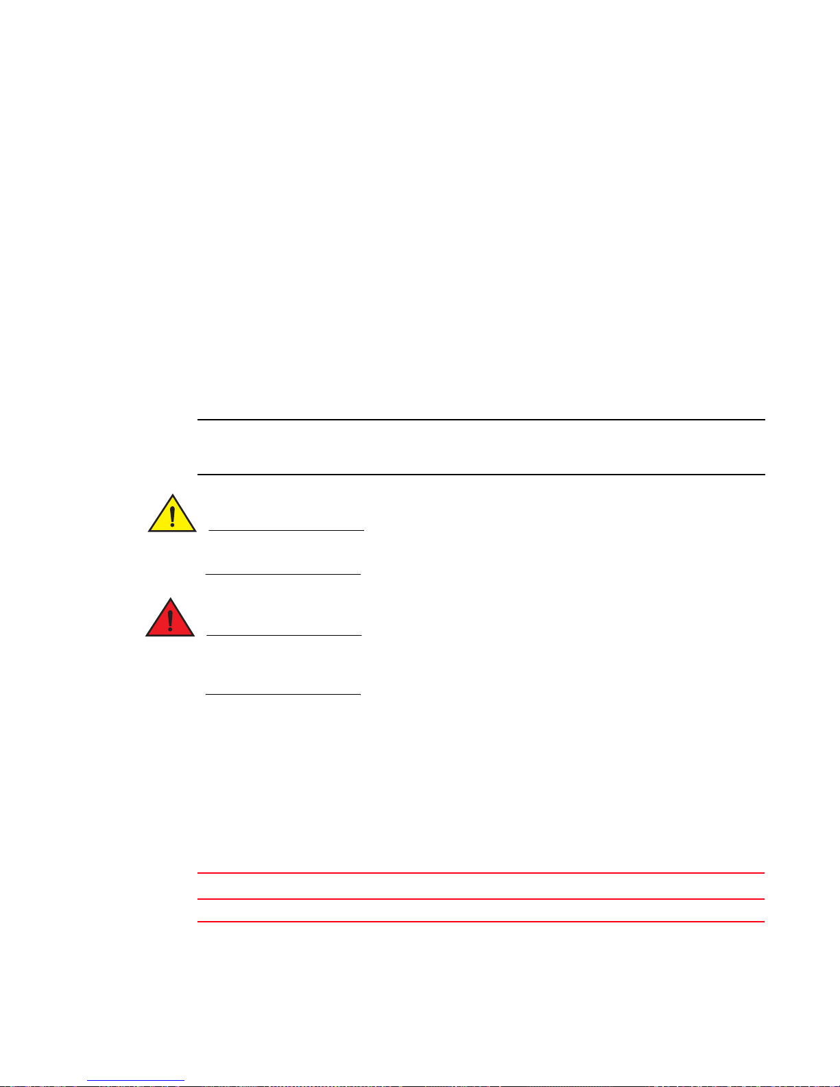
The following figures show the front and rear panels of the FastIron LS and LS -STK models.
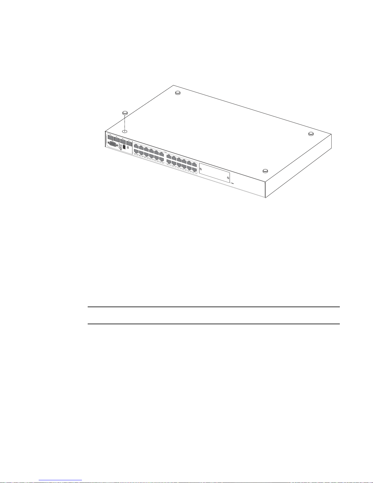
FIGURE 1 FastIron LS 624 and FastIron LS 624-STK front panel
Brocade FastIron LS and FastIron LS-STK Hardware Installation Guide 1
53-1002187-01
Page 12
Hardware features
45 484746
FastlronLS 648
FLS 648
RPSDCIn12V 13A
100-240V~
50-60Hz 2A
FLS 624
FastlronLS 624
RPSDCIn12V 13A
100-240V~
50-60Hz 2A
1
DRAFT: BROCADE CONFIDENTIAL
FIGURE 2 FastIron LS 648 and FastIron LS 648-STK front panel
FIGURE 3 FastIron LS 624 and 648 rear panel
FIGURE 4 FastIron LS 624 or FastIron LS 624-STK front panel with optional module installed
FIGURE 5 FastIron LS 624-STK and FastIron LS 648-STK rear panel
Control features
The front panel on each device includes the following control features:
• Serial management interface (the port labeled Console)
• Reset button
Serial management interface (Console port)
The serial management interface allows you to configure and manage the device using a
third-party terminal emulation application on a directly connected PC. A straight-through EIA or TIA
DB-9 serial cable (M or F) ships with the device. The serial management interface (the Console
port) is located in the right corner of the front panel.
Reset button
The reset button allows you to restart the system without removing power or using the CLI or Web
Management Interface. The button is located to the left of the serial management interface and is
recessed to prevent it from being pushed accidentally.
FastIron LS and LS-STK network interfaces
FLS and FLS-STK devices provide the following interfaces:
• 10/100/1000 Mbps ports with RJ45 copper connectors
• 100/1000 Mbps ports with mini-GBIC slots for SFP MSA-compliant fiber transceivers
2 Brocade FastIron LS and FastIron LS-STK Hardware Installation Guide
53-1002187-01
Page 13

DRAFT: BROCADE CONFIDENTIAL
Hardware features
1
• Optional 10 Gbps uplink modules (not available for FastIron LS 648-STK models)
For information about the type of fiber optic modules supported, see “Fiber optic modules” on
page 7.
FastIron LS and LS-STK 10/100/1000BASE-T ports
FLS and FLS-STK devicees contain 24 or 48 ports that operate at 10 Mbps or 100 Mbps, half or full
duplex, or at 1000 Mbps, full duplex. Because all ports on these devicees support automatic
MDI/MDI-X operation, you can use straight-through cables for all network connections to PCs or
servers, or to other devicees or hubs. (Refer to “Pinouts and signaling” on page 63.) It is best to use
MDIX cable for device-to-device connections.
Each of these ports support auto-negotiation, so the optimum transmission mode (half or full
duplex), and data rate (10, 100, or 1000 Mbps) can be selected automatically. If a device
connected to one of these ports does not support auto-negotiation, the communication mode of
that port can be configured manually.
Network interfaces
Tab le 1 describes the network interfaces supported on FastIron LS devices.
TABLE 1 Supported network interfaces
Interface Show media description
1000Base-BX-D M-GBXD
1000Base-BX-U M-GBXU
1000Base-LHA M-LHA
1000Base-LHB M-LHB
1000Base-LX M-LX
1000Base-SX M-SX
1000Base-SX2 M-SX2
1000Base-T C
100Base-BX M-FBX
100Base-FX M-FX
10GBase-CX4 XG-ER
10GBase-CX4 (XFP) XG-ER
10GBase-ER XG-ER
10GBase-LR XG-LR
10GBase-LRM XG-LRM
10GBase-SR XG-SR
10GBase-ZR XG-ZR
10GBase-ZRD XG-ZRD
1310-MMF 10GbE 1310-NM
Brocade FastIron LS and FastIron LS-STK Hardware Installation Guide 3
53-1002187-01
Page 14
Hardware features
NOTE
1
DRAFT: BROCADE CONFIDENTIAL
10 Gbps Ethernet module slots for standalone devices
FLS 624 and FLS 648 standalone devices include two slots on the rear panel for single-port
10GBASE uplink modules with XFP transceivers, and a single port CX4 module. The 10GBASE
transceivers operate at 10 Gbps full duplex with support for asymmetric flow control (that is, the
port honors incoming pause frames, but does not originate pause frames).
10 Gbps Ethernet module slots for stacking devices
FLS 624-STK and FLS 648-STK devices include two 10 Gbps Ethernet CX4 modules on the rear
panel (the stacking ports). The FLS 624-STK has an additional slot on the front panel that supports
an optional 10 Gbps CX4 module.
10 Gbps CX4 ports
The single-port CX4 module is installed in the FLS 624 and FLS 648 (shown in Figure 6). You can
order the FastIron LS with a single-port CX4 module pre-installed, or you can upgrade your device at
a later time. This module is a 10 GbE-CX4 Ethernet uplink card, capable of performing data
transmission directly through copper links to 15m (extended 30m) in length.
Single-port CX4 uplink for 10 Gbps is supported.
Link and Activity LEDs on the module faceplates indicate operational status:
• If the Link LED is on, the port is connected. If the Link LED is off, no connection exists, or the
link is down.
• If the Act LED is on or blinking, traffic is being transmitted and received on the port. If the Act
LED is off, no traffic is being transmitted or received on the port.
FIGURE 6 Single-port 10 Gbps Ethernet CX4 module
Cable specifications
The following cable specifications apply to the CX4 port in the 10GbE interface module (FLS-1XGC):
• Support for 802.3ak or 10 Gbps Ethernet CX4 standard
• Support for cables up to 15m in length
• Requires latch-style receptacle or SFF-8470 plug
• Recommended CX4 cable is manufactured by WL Gore, part number IBN6600-15, CX4
Assembly - 26AWG SPC 15.0m
The recommended CX4 cable can also be used with a Small Form Factor Pluggable (XFP)
MSA-compliant optical transceiver (part number FLS-1XGC).
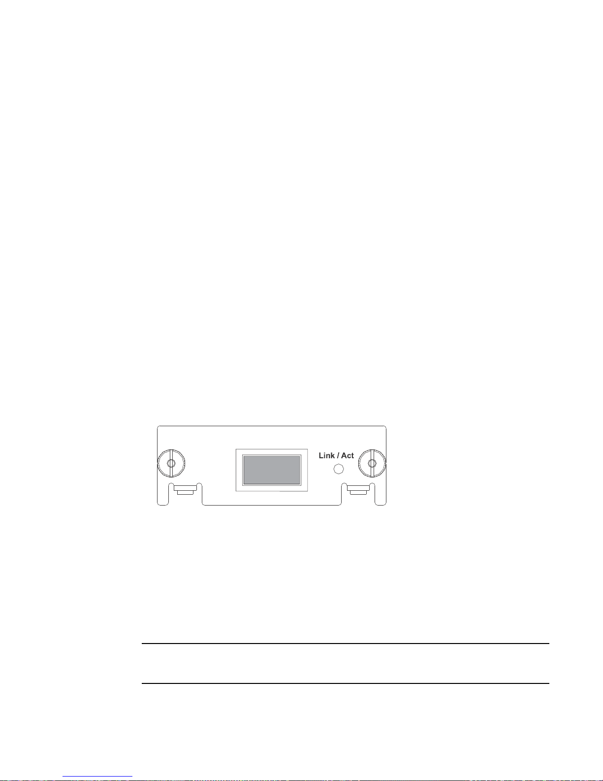
Figure 7 shows the CX4-grade cable.
4 Brocade FastIron LS and FastIron LS-STK Hardware Installation Guide
53-1002187-01
Page 15
DRAFT: BROCADE CONFIDENTIAL
1
FIGURE 7 CX4 transceiver cable
FIGURE 8 CX4 slide-in transceiver
Hardware features
1
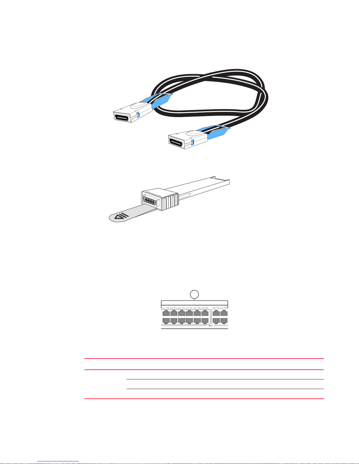
Port, system, and module status LEDs
FastIron LS and LS-STK devices include key system and port indicators to simplify installation and
network troubleshooting. These LEDs, located on the front panel for easy viewing, are shown in
Figure 9 and described in the following tables.
FIGURE 9 Port status LEDs
1 Port status LED
TABLE 2 Port status LEDs
LED Status Status
Link/
Activity or Speed
On or Flashing Amber Port has a valid link at 10 or 100 Mbps. Flashing indicates activity.
On or Flashing Green Port has a valid link at 1000 Mbps. Flashing indicates activity.
Off The link is down.
Brocade FastIron LS and FastIron LS-STK Hardware Installation Guide 5
53-1002187-01
Page 16

Hardware features
1
FLS 624
Fastlron LS 624
1
DRAFT: BROCADE CONFIDENTIAL
FIGURE 10 System status LEDs
1System status LED
TABLE 3 System status LEDs
LED Condition Status
Power Green Internal power is operating normally.
Amber Internal power supply failure.
Off Power off or failure.
Diag Green System self-diagnostic test successfully completed.
Amber System self-diagnostic test has detected a fault.
RPS Green Redundant power supply is providing power.
Amber Primary power supply is active, RPS is on standby.
Off Redundant power supply is off or not plugged in.
Stack Active
controller
Stack Link Green Uplink and downlink operating normally.
Module Green An expansion module is installed and operating normally.
Stack ID 1-8 Indicates the device stack ID.
Green Device is the Active Controller of the stack. State may include topology
discovery, IP assignment, or normal operations.
Flashing Green Device is the Active Controller of the stack, system is initializing.
Amber Device is operating as a Standby Controller in the stack.
Flashing Amber System in Active Controller arbitration or election state.
Off System in standalone mode.
Flashing Green Uplink has failed.
Flashing Amber Downlink has failed.
Off No stacking link present.
Amber An expansion module is installed but has failed.
Off There is no module installed.
The Active Controller is numbered 1. (Note that If the Active Controller
fails and a backup unit takes over, the stack IDs do not change.)
The Standby Controller is numbered 2. The remaining stack members
are numbered 3-8.
0 A standalone device. A device with a stack ID of 0 cannot act as part
of a stack.
6 Brocade FastIron LS and FastIron LS-STK Hardware Installation Guide
53-1002187-01
Page 17
DRAFT: BROCADE CONFIDENTIAL
NOTE
DANGER
1
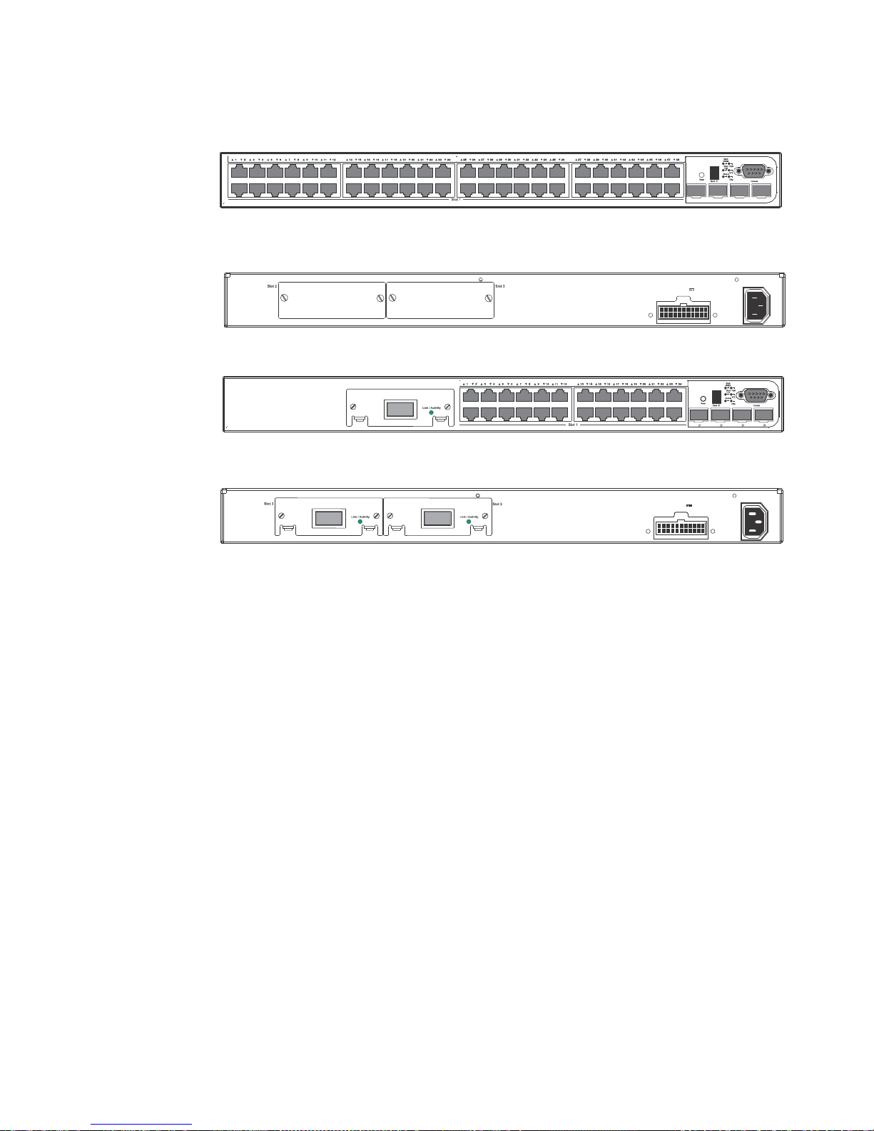
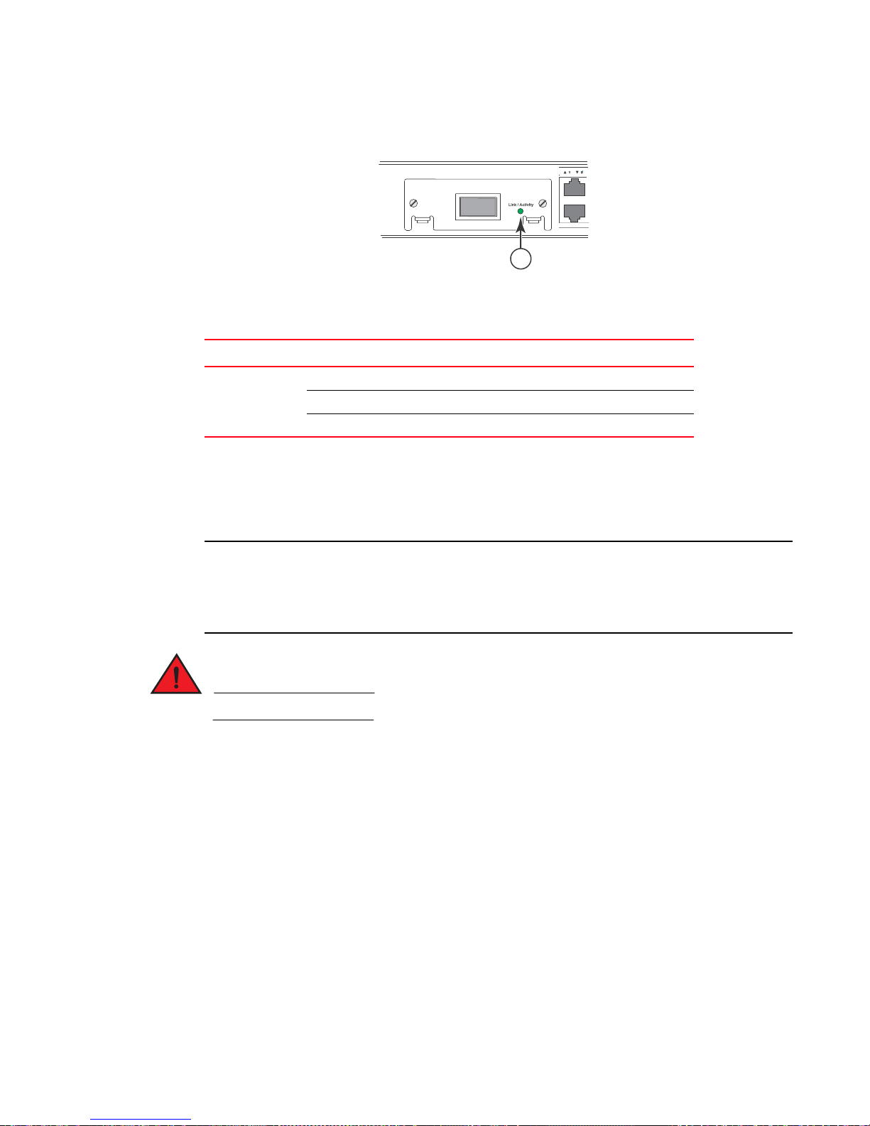
FIGURE 11 Module Link/Activity LED
1 Link/Activity LED
TABLE 4 Module Link/Activity LED
LED Condition Status
Link or Activity On Port has a valid link at 10 Gbps.
On or Flashing Green Flashing indicates activity.
Off The link is down.
Fiber optic modules
Hardware features
1
A list of the types of fiber optic modules supported on Layer 2 Compact devicees can be found in
“Cable specifications” on page 64
Some older SFP modules (mini-GBICs for Gbps Ethernet ports) have latching mechanisms that are
larger than the newer parts. These latches could interfere with one another when inserted side by
side in the same module. These older modules are identified by the number PL-XPL-00-S13-22 or
PL-XPL-00-L13-23 above the serial number. All newer mini-GBICs do not have this limitation.
All fiber optic interfaces use Class 1 lasers.
Power supplies
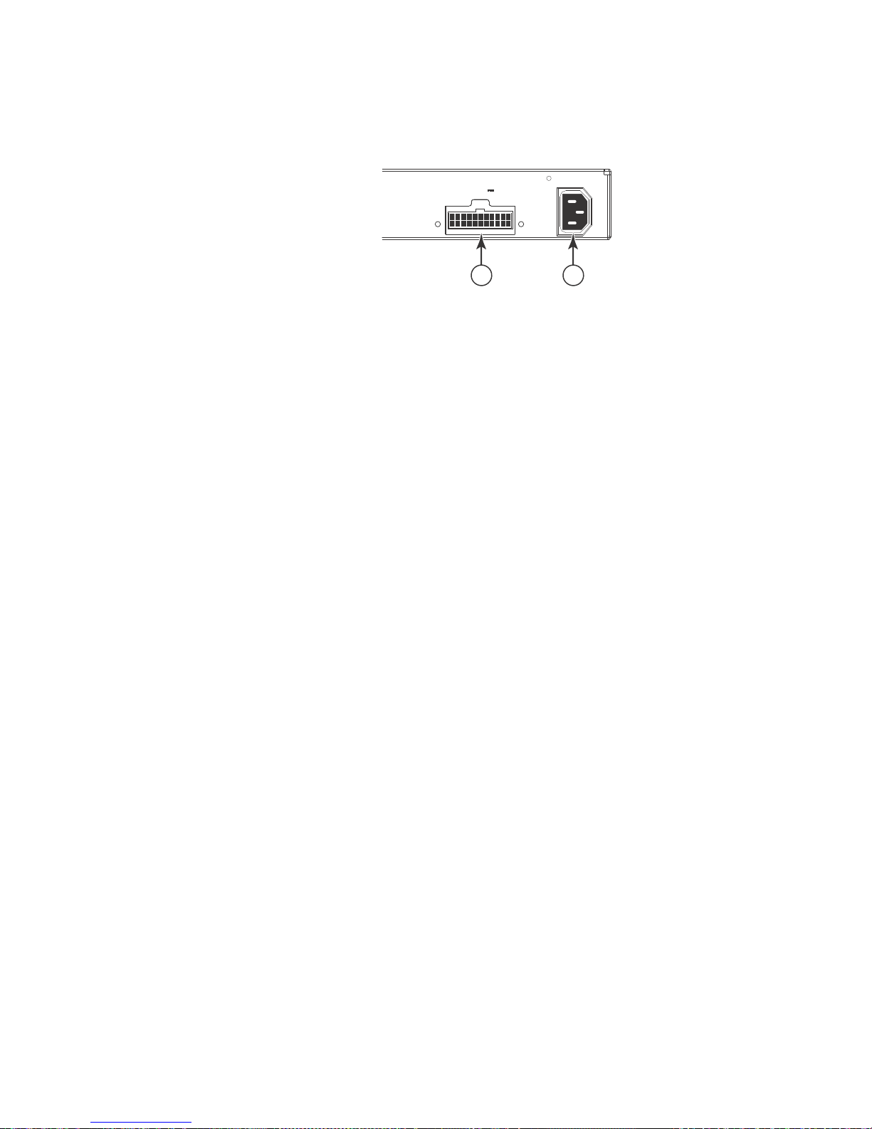
There are two power receptacles on the rear panel of each device. The standard power receptacle
is for the AC power cable. The receptacle labeled “RPS” is for the optional redundant power supply.
Optional redundant power supply
The device supports an optional redundant power supply (RPS), that can supply power in the event
the internal power supply fails.
Power supply receptacles
There are two power receptacles on the rear panel of each device. The standard power receptacle
is for the AC power cable. The receptacle labeled “RPS” is for the optional redundant power supply.
Brocade FastIron LS and FastIron LS-STK Hardware Installation Guide 7
53-1002187-01
Page 18
Hardware features
RPS DC In 1 2V 13A
100-240V~
50-60Hz 2A
1 2
1
DRAFT: BROCADE CONFIDENTIAL
FIGURE 12 Power supply receptacles
1 Redundant Power Socket
2 Power Socket
8 Brocade FastIron LS and FastIron LS-STK Hardware Installation Guide
53-1002187-01
Page 19

DRAFT: BROCADE CONFIDENTIAL
DANGER
Chapter
Installing an FLS or FLS-STK device
Unpacking a system
The procedures in this manual are intended for qualified service personnel.
This chapter describes how to physically install a FastIron LS or FastIron LS-STK device.
For information about configuring IP addresses and connecting network devices, see Chapter 4,
“Connecting Network Devices and Checking Connectivity”.
For information about configuring an IronStack using FLS624-STK and FLS648-STK devices, see
the FastIron Configuration Guide.
Brocade FLS and FLS-STK devices ship with all of the items listed below. Please review this list and
verify the contents of your shipping container. If any items are missing, please contact the place of
purchase.
2
FLS624-STK and FLS648-STK devices come with a 0.5 meter 10GBASE CX4 cable.
Package contents for standalone FLS devices
Package contents for standalone FLS devices include:
• FastIron LS device
• 115V AC power cable (for AC devices)
• Rack mount brackets
• Warranty card
Package contents for FLS-STK devices
Package contents for FLS-STK devices included:
• FastIron LS-STK device
• 115V AC power cable (for AC devices)
• Rack mount brackets
• Warranty card
• 10GBASE CX4 (FLS624-STK only)
• 0.5m CX4 cable
Brocade FastIron LS and FastIron LS-STK Hardware Installation Guide 9
53-1002187-01
Page 20

DRAFT: BROCADE CONFIDENTIAL
Summary of installation tasks
2
General requirements
To manage the system through a serial connection, you will need the following items:
• A management station, such as a PC running a terminal emulation application.
• A straight-through EIA or TIA DB-9 serial cable (F/F). The serial cable can be ordered separately
from Brocade. If you prefer build your own cable, see the pinout information in “Attaching a PC
or terminal” on page 27.
Use the serial connection to perform basic configuration tasks, including assigning an IP address
and network mask to the system. This information is required to manage the system using the Web
management interface or IronView or using the CLI through Telnet.
Summary of installation tasks
Follow the steps listed below to install your FastIron LS or LS-STK device. Details for each step are
provided in this chapter and in the following chapter.
TABLE 5 Installation tasks
Task
number
Task Where to find more information
1 Ensure that the physical environment that will host
the device has the proper cabling and ventilation.
2 Install any required optional modules into the device. “Installing an optional module in the device”
3 Install the Brocade device on a desktop, in an
equipment rack.
4 Connect stackable devices in an IronStack topology. “Connecting devices in a stack” on page 15
5 Once the device is physically installed, plug the
device into a nearby power source that adheres to
the regulatory requirements outlined in this manual.
6 Verify that the system LEDs are registering the proper
LED state after power-on of the system.
7 Attach a terminal or PC to the Brocade device. This
will enable you to configure the device through the
Command Line Interface (CLI).
8 No default password is assigned to the CLI. For
additional access security, assign a password.
9 Before attaching equipment to the device, you need
to configure an interface IP address to the subnet on
which it will be located. Initial IP address
configuration is performed using the CLI with a direct
serial connection. Subsequent IP address
configuration can be performed using the Web
management interface.
10 Once you power on the device and assign IP
addresses, the system is ready to accept network
equipment.
“Preparing the installation site” on page 13
on page 25
“Installing the device” on page 13
“Powering on the system” on page 26
“Verifying proper operation” on page 27
“Attaching a PC or terminal” on page 27
“Assigning permanent passwords” on
page 37
“Configuring IP addresses” on page 39
“Devices running base layer 3 software” on
page 40
10 Brocade FastIron LS and FastIron LS-STK Hardware Installation Guide
53-1002187-01
Page 21
DRAFT: BROCADE CONFIDENTIAL
DANGER
CAUTION
CAUTION
CAUTION
TABLE 5 Installation tasks (Continued)
Task
number
11 Test IP connectivity to other devices by pinging them
12 Continue configuring the device using the CLI or the
13 Secure access to the device. FastIron Configuration Guide
Task Where to find more information
and tracing routes.
Web management interface. You also can use
IronView to manage the device. Refer to the IronView
Network Manager User Guide for information.
Installation precautions
Follow these precautions when installing a Brocade device.
General precautions
Installation precautions
“Testing connectivity” on page 46
FastIron Configuration Guide
2
All fiber optic interfaces use Class 1 lasers.
Do not install the device in an environment where the operating ambient temperature might
exceed 50
C (121
F).
Make sure the air flow around the front and sides of the device is not restricted.
Never leave tools inside the device.
Brocade FastIron LS and FastIron LS-STK Hardware Installation Guide 11
53-1002187-01
Page 22
Installation precautions
DANGER
DANGER
CAUTION
CAUTION
CAUTION
DANGER
DANGER
2
DRAFT: BROCADE CONFIDENTIAL
Lifting precautions
Make sure the rack or cabinet housing the device is adequately secured to prevent it from
becoming unstable or falling over.
Mount the devices in the lowest possible slots in a rack or cabinet. Place the heaviest device at
the bottom and progressively place lighter devices above.
Power precautions
Use a separate branch circuit for each AC power cable, which provides redundancy in case one of
the circuits fails.
To avoid high voltage shock, do not open the device while the power is on.
Ensure that the device does not overload the power circuits, wiring, and over-current protection.
To determine the possibility of overloading the supply circuits, add the ampere (amp) ratings of all
devices installed on the same circuit as the device. Compare this total with the rating limit for the
circuit. The maximum ampere ratings are usually printed on the devices near the input power
connectors.
Disconnect the power cable from all power sources to completely remove power from the device.
If the installation requires a different power cable than the one supplied with the device, make
sure you use a power cable displaying the mark of the safety agency that defines the regulations
for power cords in your country. The mark is your assurance that the power cable can be used
safely with the device.
12 Brocade FastIron LS and FastIron LS-STK Hardware Installation Guide
53-1002187-01
Page 23

DRAFT: BROCADE CONFIDENTIAL
DANGER
DANGER
Preparing the installation site
Cabling infrastructure
Ensure that the proper cabling is installed at the site. Refer to Chapter 7, “Hardware Specifications”
or visit www.brocade.com for a summary of supported cabling types and their specifications.
Installation location
Before installing the device, plan the location and orientation relative to other devices and
equipment. Devices can be mounted in a standard 19-inch equipment rack or on a flat surface. Be
sure to follow the guidelines below when choosing a location.
The site should:
• Maintain temperatures within 0 to 50
non-condensing.
• Allow a minimum of 3 inches of space between the sides and the back of the device and walls
or other obstructions for proper air flow.
• Allow at least 3 inches of space at the front and back of the device for the twisted pair, fiber
optic, and power cables.
• Be accessible for installing, cabling, and maintaining the devices.
• Allow the status LEDs to be clearly visible.
• Allow twisted pair cable to always be routed away from power lines, fluorescent lighting fixtures,
and other sources of electrical interference, such as radios and transmitters.
• Allow the device to be connected to a separate grounded power outlet that provides 100 to
240 VAC, 50 to 60 Hz, is within 2 meters (6.6 feet) of each device and is powered from an
independent circuit breaker. As with any equipment, a filter or surge suppressor is
recommended.
Preparing the installation site
C (32 to 122F) and humidity levels within 5% to 95%,
2
Installing the device
You can install Brocade devices on a desktop or in an equipment rack.
Make sure the rack or cabinet housing the device is adequately secured to prevent it from
becoming unstable or falling over.
Mount the devices in the lowest possible slots in a rack or cabinet. Place the heaviest device at
the bottom and progressively place lighter devices above.
Brocade FastIron LS and FastIron LS-STK Hardware Installation Guide 13
53-1002187-01
Page 24
Preparing the installation site
NOTE
2
Desktop installation
FIGURE 13 Attaching the adhesive feet
DRAFT: BROCADE CONFIDENTIAL
4
2
6
S
L
n
o
r
l
t
s
a
F
624
S
L
F
1. Attach the four adhesive feet to the bottom of the first device.
2. Set the device on a flat desktop, table, or shelf near an AC power source. Make sure that
adequate ventilation is provided for the system – a 3 inch clearance is recommended on each
side.
3. If you are installing a single device, go to “Powering on the system” on page 26.
4. If you are installing multiple devicees, attach the adhesive feet to each device. Place each
device squarely on top of the one below, in any order.
5. If you are also installing a redundant power supply, place it close to the device.
Rack mount installation
You need a #2 Phillips screwdriver for installation.
Before mounting the device in a rack, pay particular attention to the following factors:
• Temperature: Since the temperature inside a rack assembly may be higher than the ambient
room temperature, make sure the rack-environment temperature is within the specified
operating temperature range. (Refer to “Operating environment” on page 60.)
• Mechanical loading: Do not place any equipment on top of a rack-mounted unit.
• Circuit overloading: Be sure that the supply circuit to the rack assembly is not overloaded.
• Grounding: Rack-mounted equipment should be properly grounded. Particular attention should
be given to supply connections other than direct connections to the mains.
Follow the steps below to mount devices in rack.
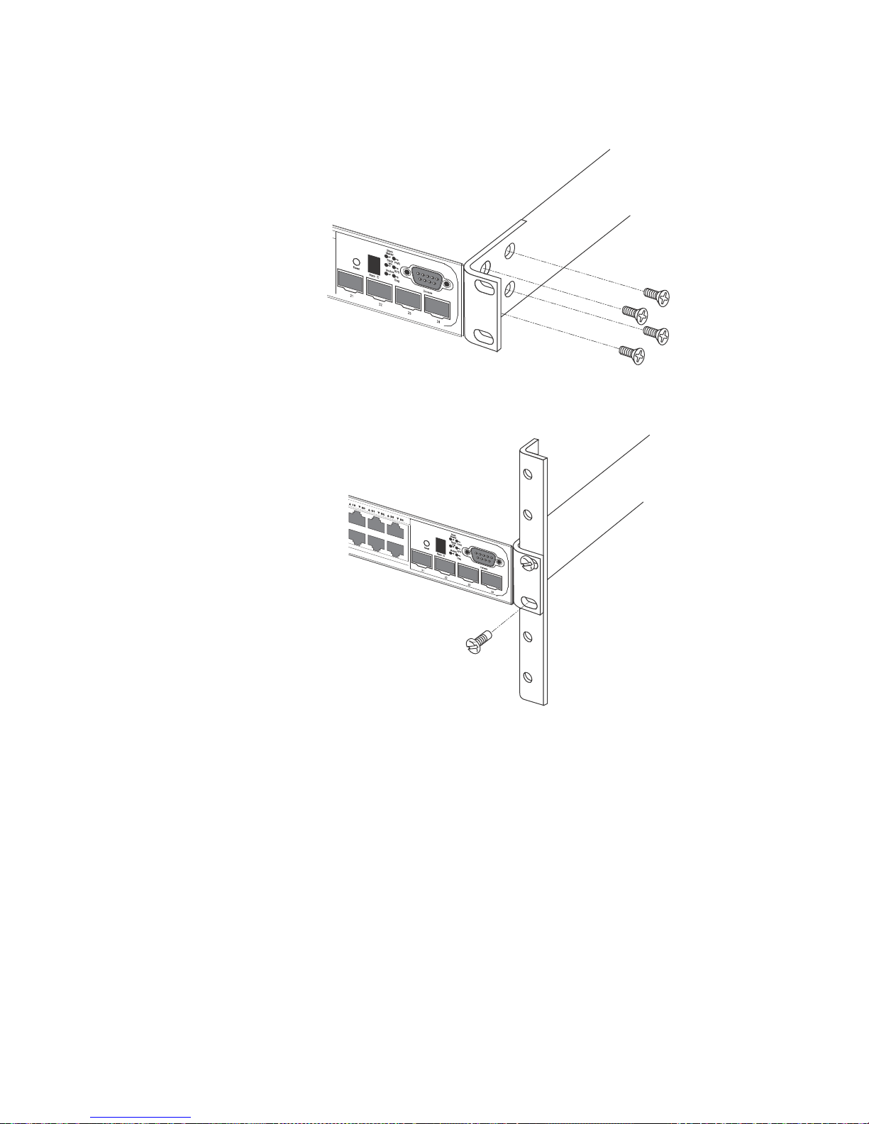
1. Remove the rack mount kit from the shipping carton. The kit contains two L-shaped mounting
brackets and mounting screws.
2. Attach the mounting brackets to the sides of the device as illustrated in Figure 14.
14 Brocade FastIron LS and FastIron LS-STK Hardware Installation Guide
53-1002187-01
Page 25
DRAFT: BROCADE CONFIDENTIAL
Fastlron
LS
624
FLS
624
624
Fastlron
LS
624
FLS
Preparing the installation site
FIGURE 14 Attaching the brackets
3. Attach the device in the rack as illustrated in Figure 15.
FIGURE 15 Installing the device in a rack
2
4. If you are installing a single device, proceed to “Powering on the system” on page 26.
5. If you are installing multiple devices, mount them in the rack, one below the other, in any order.
6. If you are also installing a redundant power supply, mount it in the rack below the other
devices.
Connecting devices in a stack
Figure 16 shows how the stack cables are connected between devices in a stack. The connection is
based on 10 Gbps Ethernet, using CX4 cables. FLS-STK devices support linear and ring stack
topologies, and can also operate as standalone devices. For detailed information about configuring
and managing an IronStack, see the FastIron Configuration Guide.
Brocade FastIron LS and FastIron LS-STK Hardware Installation Guide 15
53-1002187-01
Page 26

Preparing the installation site
NOTE
2
In a linear stack topology there is a single stack cable connection between each device that carries
two-way communications across the stack. In a ring stack topology, an extra cable is connected
between the top and bottom devices forming a “ring” or “closed-loop.” The closed-loop cable
provides a redundant path for the stack link, so if one link fails, stack communications can be
maintained.
You can build a stack containing up to 8 FastIron LS-STK units. Follow the steps below to connect
devices in a stack.
1. Plug one end of a stack cable into one of the CX4 stacking ports of the top unit.
2. Plug the other end of the stack cable into one of the stacking ports of the next unit.
3. Repeat steps 1 and 2 for each unit in the stack. Form a simple chain starting with a stacking
4. (Optional) To form a ring stack topology, plug one end of a stack cable into the remaining
DRAFT: BROCADE CONFIDENTIAL
port on the top unit and ending at a stacking port on the bottom unit (stacking up to 8 units).
stacking port on the bottom unit and the other end into the remaining stacking port on the top
unit.
Use the .5 meter CX4 cables that shipped with each FLS-STK device to connect a linear stack
topology. For a ring topology, you will need an additional, longer (3.0 meter) CX4 cable.
The total maximum stacking distance in linear and ring stack topologies is 1,000 meters
(3,281 feet). This length can consist of multiple inter-device stacking connections adding up to
1,000 meters. A single inter-device stacking connection should not exceed 1,000 meters.
Tab le 6 lists the recommended cable lengths for XFP cabling for various connection distances:
TABLE 6 XFP optical link cable distances
Data rate Fiber type Modal bandwidth @
850nm (Mhz-km)
62.5/125um MMF 160 2 - 26
9.95-10.3125
Gbps
NOTE: Average distance range is between 2 - 33 meters. Brocade recommends using the 2000 bandwidth
version for distances greater than 80 meters.
62.5/1.25um MMF 200 2 - 33
50/125um MMF 400 2 - 66
50/123um MMF 500 2 - 82
50/125um MMF 2000 2 - 300 >400
Worst case distance range
specified (m)
Typical range (m)
16 Brocade FastIron LS and FastIron LS-STK Hardware Installation Guide
53-1002187-01
Page 27

DRAFT: BROCADE CONFIDENTIAL
Installing a redundant power supply
FIGURE 16 Connecting devicees in a ring topology stack
One device in the stack operates as the Active Controller, one operates as the Standby Controller,
with the rest of the units operating as stack members. For information about how to configure your
stack, see the FastIron Configuration Guide.
2
Installing a redundant power supply
About the RPS2-EIF redundant power supply
The Brocade External Redundant Power Supply (RPS2-EIF) can supply a maximum of 150 Watts of
output power per port, a total of 600 Watts of backup power to four FastIron devices in the event of
an AC loss or failure of an internal power supply.
The RPS device operates as a backup to the internal power supply. If then internal power supply
fails, the RPS device will support the full load of the device without affecting network operation.
FastIron LS624 and FastIron LS648 devices support the RPS2-EIF power supply.
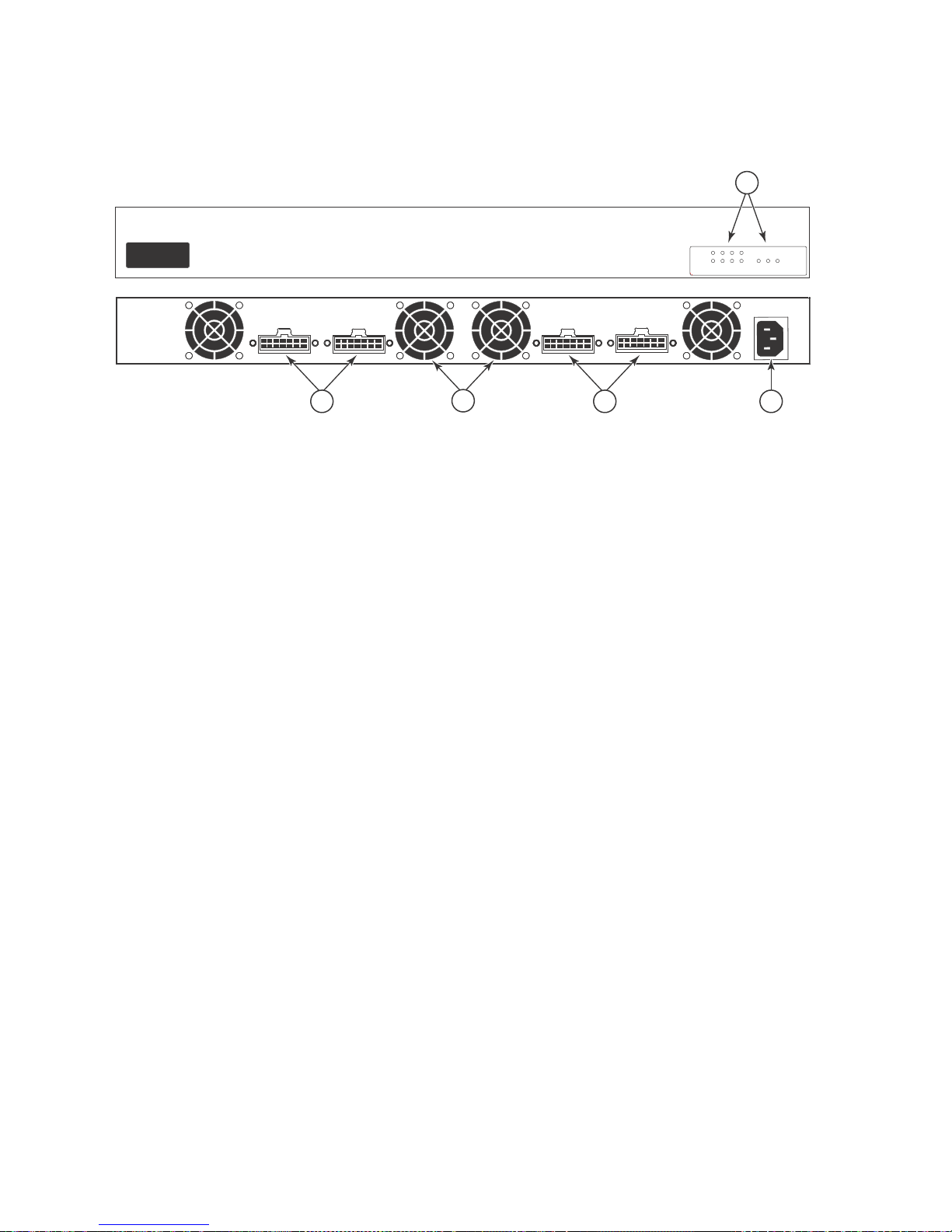
Fan and power indicators and receptacles
Four power indicators and one fan indicator are located on the front panel of the RPS device. The
AC supply and DC backup receptacles are located on the RPS device rear panel.
Brocade FastIron LS and FastIron LS-STK Hardware Installation Guide 17
53-1002187-01
Page 28
Installing a redundant power supply
Link
Activity
12
3
4
FanThermal Power
100-240V,50-60Hz 10A
RPS 1
RPS 2RPS 3RPS 4
4
3
2
1
5
2
FIGURE 17 Front and rear panels showing fan and power indicators and power receptacles
1 Redundant Power Sockets 4 Power Socket
2 Fans 5 Port and System Status Indicators
3Redundant Power Sockets
DRAFT: BROCADE CONFIDENTIAL
Package contents
The RPS shipping package contains:
• Redundant Power Supply device (RPS2-EIF)
• One AC power cable — US, Continental Europe or UK
• Four DC backup power cords with IEC connectors on both ends (length 152 cm each)
• Rack Mounting Kit containing brackets and screws
• Adhesive feet
• User Agreement envelope
• Registration card
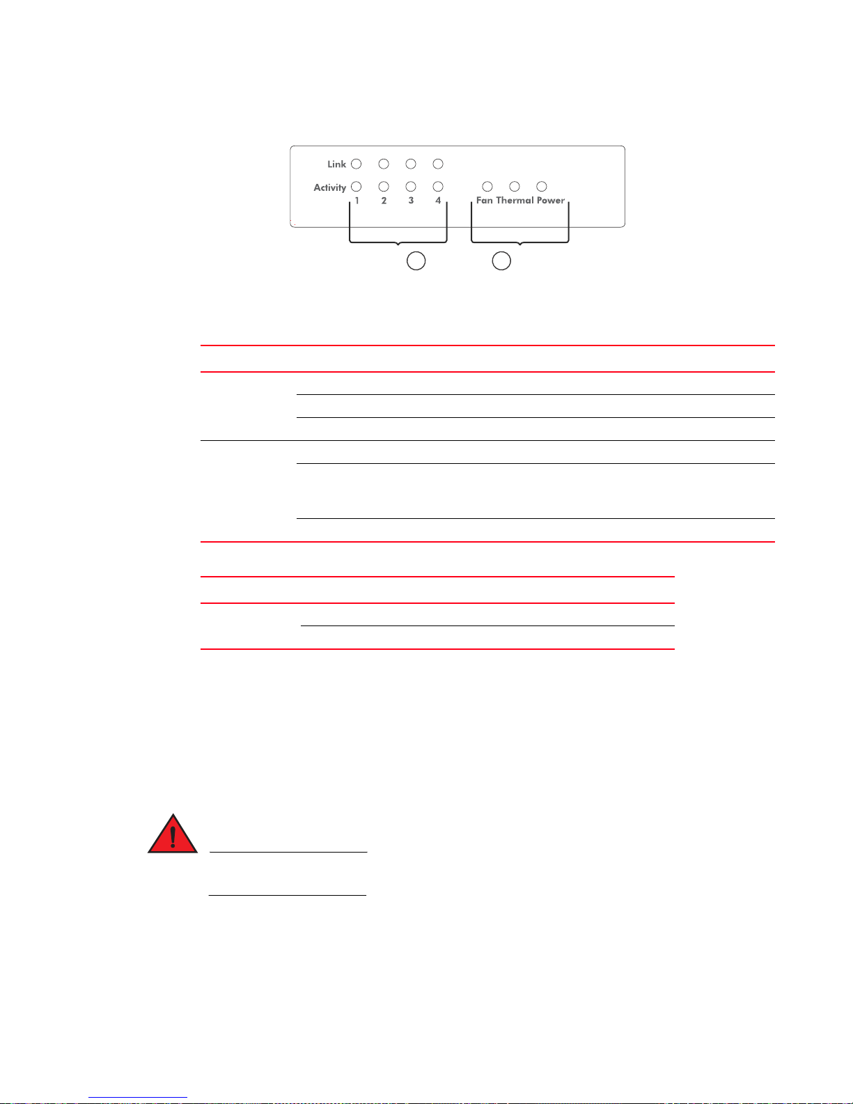
LEDs
Figure 18 and Table 7 and Table 8 describe the functions of the RPS2-EIF LEDs.
18 Brocade FastIron LS and FastIron LS-STK Hardware Installation Guide
53-1002187-01
Page 29
DRAFT: BROCADE CONFIDENTIAL
DANGER
21
Installing a redundant power supply
FIGURE 18 RPS2-EIF Status LEDs
1 Port Indicators 2 System Indicators
TABLE 7 RPS2-EIF status LEDs
LED (1~4) Condition Status
Link Off The port does not have a valid connection to a device.
On Yellow The port has a valid connection to a device.
Flashing Yellow There has been a RPS device internal power failure.
Activity Off The port is not providing power to the connected device.
Flashing Green The port has been shut down due to one of the following conditions:
• The system has detected an over-current condition.
• One or more of the fans have failed.
On Green The port is providing power to a connected device.
2
TABLE 8 RPS2-EIF power status LED
LED Condition Status
Power On Green AC power is being supplied to the RPS.
Off No AC power is being supplied to the RPS device.
Installing a redundant power supply
Installation
An RPS device may be placed on a desktop or mounted in a rack.
DO NOT place an RPS device on the floor as the case is not waterproof. It is recommended that
RPS devices be installed in a network equipment rack.
Selecting a site
RPS2-EIF units can be mounted in a standard 19 inch equipment rack or on a flat surface. When
choosing a location, follow the guidelines below:
Brocade FastIron LS and FastIron LS-STK Hardware Installation Guide 19
53-1002187-01
Page 30

Installing a redundant power supply
2
• The site should:
• Be at the center of all the devices you want to link and near a power outlet.
• Maintain temperatures within 0 to 50 °C (32 to 121 °F) and humidity levels within 5% to
• Provide adequate space (approximately two inches) on all sides for proper air flow
• Be accessible for installing, cabling, and maintaining the devices
• Allow the status LEDs to be clearly visible
• Allow twisted-pair cable to always be routed away from power lines, fluorescent lighting fixtures
and other sources of electrical interference, such as radios and transmitters.
• Provide a separate grounded power outlet that provides 100 to 240 VAC, 50-60 Hz, is within
2.44 m (8 feet) of each device and is powered from an independent circuit breaker. As with any
equipment, Brocade recommends a filter or surge suppressor.
Equipment checklist
After unpacking the FastIron RPS2-EIF device, check the contents to be sure you have received all
the components. (See “Package contents” on page 18.) Before beginning the installation, be sure
you have all other necessary installation equipment.
DRAFT: BROCADE CONFIDENTIAL
95%, non-condensing
Optional rack-mounting equipment
If you plan to rack-mount the RPS device, be sure to have the following equipment available:
• Four mounting screws for each device you plan to install in a rack, these are not included
• A screwdriver (Phillips or flathead, depending on the type of screws used)
Mounting
FastIron RPS devices can be mounted in a standard 19 inch equipment rack or on a desktop or
shelf. Mounting instructions for each type of site follow.
Rack mounting
Before mounting the unit in a rack, pay particular attention to the following factors:
• Temp eratu re: Since the temperature within a rack assembly may be higher than the ambient
room temperature, make sure the rack-environment temperature is within the specified
operating temperature range.
• Mechanical loading: Do not place any equipment on top of a rack-mounted unit.
• Circuit overloading: Make sure that the supply circuit to the rack assembly is not overloaded.
• Grounding: Rack-mounted equipment should be properly grounded. Particular attention should
be given to supply connections other than direct connections to the mains.
Follow the steps below to mount devices in a rack.
20 Brocade FastIron LS and FastIron LS-STK Hardware Installation Guide
53-1002187-01
Page 31

DRAFT: BROCADE CONFIDENTIAL
Lin
k
Ac
ti
vit
y
12
3
4
Fa
nThermal Power
Installing a redundant power supply
1. Attach the brackets to the device using the screws provided in the rack mounting kit.
FIGURE 19 Attaching the brackets
2. Mount the device in the rack, using four rack-mounting screws (not provided).
FIGURE 20 Installing the RPS device in a rack
2
3. If installing multiple RPS devices, mount them in the rack, one below the other, in any order.
Brocade FastIron LS and FastIron LS-STK Hardware Installation Guide 21
53-1002187-01
Page 32

Installing a redundant power supply
100-240V, 50-60Hz 10A
RPS 1
2
Desktop or shelf mounting
1. Attach the four adhesive feet to the bottom of the first RPS device.
FIGURE 21 Attaching the adhesive feet
DRAFT: BROCADE CONFIDENTIAL
2. Set the device on a flat surface near an AC power source, making sure there are at least two
inches of space on all sides for proper air flow.
Connecting devices to the redundant power supply
The RPS2-EIF unit can be used with all FastIron LS and FastIron LS-STK devices.
Follow the steps below to connect devices to the redundant power supply.
1. Connect one end of the AC cable to the AC receptacle on the supported device, and the other
end to a grounded power outlet.
FIGURE 22 Power receptacle
2. Connect one end of a DC cable to the redundant power receptacle on the supported device
and the other end to an available receptacle on the RPS device.
3. Repeat steps 1 and 2 for connecting up to four supported devices to the RPS device.
4. Connect one end of the AC cable to the AC receptacle on the RPS device, and the other end to
a grounded power outlet.
22 Brocade FastIron LS and FastIron LS-STK Hardware Installation Guide
53-1002187-01
Page 33

DRAFT: BROCADE CONFIDENTIAL
DANGER
NOTE
1
5
3
6
4
2
Installing a redundant power supply
5. To connect additional RPS devices, first disconnect the original RPS device from the AC power
supply, then follow steps 1, 2, 4 and 5.
Once the RPS device is disconnected from the AC power supply, the RPS device will no longer
provide redundant power until after the additional RPS devices are installed, the AC power is
reconnected, and the RPS device completes the self-test procedure.
6. Check the LEDs on the RPS device to ensure proper operation. The Power LED should light up.
If it does not light, see Chapter 6, “Troubleshooting” for more information.
2
1RPS Input Port 4 FLS Units
2 AC Power Supply Number 1 5 RPS Output Port
3 RPS Unit 6 AC Power Supply Number 2
For International use, you may need to change the AC power cable. You must use a power cable that
Brocade FastIron LS and FastIron LS-STK Hardware Installation Guide 23
53-1002187-01
has been approved for the receptacle type in your country.
Page 34

Installing a redundant power supply
GND
N.C.
N.C.
GND
12 V RPS Present
12 V Status 1
12 V Status 2
12 V Power Good
GND GND
18
29
310
411
512
613
714
2
Ports pin-out (RPS2-EIF)
DRAFT: BROCADE CONFIDENTIAL
TABLE 9 Port pin-outs - RPS2-EIF
Pin Name Description
1, 7, 8, 14 GND Ground connection
2, 9 N.C. No current
3, 4, 5, 6 12 V 12 volts current
10 RPS Present Indicates that an RPS device is attached and functioning
11, 12 Status 1, Status 2 Status indicator
13 Power Good Indicates that power is being supplied to the RPS device
24 Brocade FastIron LS and FastIron LS-STK Hardware Installation Guide
53-1002187-01
Page 35

DRAFT: BROCADE CONFIDENTIAL
CAUTION
Installing an optional module in the device
Installing an optional module in the device
FIGURE 23 Installing an optional module
Follow the steps below to install an optional module into the device.
1. Remove the two mounting screws on the blank metal plate (or a previously installed module)
with a flat-head screwdriver. Remove the old module, or blank plate.
2. Before opening the package that contains the new module, touch the bag to the device casing
to discharge any potential static electricity. Brocade recommends using an ESD wrist strap
during installation.
2
3. Remove the module from the anti-static shielded bag.
4. Holding the module level, guide it into the carrier rails on each side and push it into the slot,
until it firmly engages with the connector.
5. When the module has properly engaged the connector, tighten the retainer screws to secure
the module in the slot.
6. When the device is powered on, the module LED on the device front panel should turn green to
confirm that the module is correctly installed and ready to use.
If you do not install a module in a slot, you must keep the slot panel in place. If you run the device
with an uncovered slot, the system will overheat.
Brocade FastIron LS and FastIron LS-STK Hardware Installation Guide 25
53-1002187-01
Page 36

DRAFT: BROCADE CONFIDENTIAL
NOTE
NOTE
NOTE
NOTE
Installing an SFP transceiver
2
Installing an SFP transceiver
FIGURE 24 Inserting an SFP transceiver into a slot
FL
S
624
Fastlron
LS
624
Follow the steps below to install an SFP transceiver.
1. Consider network and cabling requirements to select an appropriate SFP transceiver type.
2. Insert the transceiver with the optical connector facing outward and the slot connector facing
down. SFP transceivers are keyed so they can only be installed in one orientation.
3. Slide the SFP transceiver into the slot until it clicks into place.
SFP transceivers are hot-swappable. The device does not need to be powered off before installing
or removing a transceiver. However, always first disconnect the network cable before removing a
transceiver.
SFP transceivers are not provided in the device package.
Powering on the system
After you complete the physical installation of the system, you can power on the system.
1. Remove the power cable from the shipping package.
2. Attach the AC power cable to the AC connector on the rear panel.
3. Insert the power cable plug into a 115V/120V outlet.
To turn the system off, simply unplug the power cable or cables.
The socket should be installed near the equipment and should be easily accessible.
If the outlet is not rated 115/120V, stop and get the appropriate cable for the outlet.
26 Brocade FastIron LS and FastIron LS-STK Hardware Installation Guide
53-1002187-01
Page 37

DRAFT: BROCADE CONFIDENTIAL
NOTE
NOTE
Verifying proper operation
After you have installed a redundant power supply, verify that the device is working properly by
plugging it into a power source and verifying that it passes the self test.
1. Connect the power cable supplied with the device to the power connector on the power supply
on the rear panel.
2. Insert the other end into a properly grounded electrical outlet.
The devices do not have power switches. They power on when you connect a power cable to the
device and to a power source.
If your installation requires a different power cable than that supplied with the device, make
sure you obtain a power cable displaying the mark of the safety agency that defines the
regulations for power cables in your country. The mark is your assurance that the power cable
can be used safely with the device.
3. Verify that the LED for the power supply is green.
4. Verify proper operation by observing the LEDs:
Verifying proper operation
2
All of the port LEDs should flash momentarily, usually in sequence, while the device performs
diagnostics. After the diagnostics are complete, the LEDs will be dark except for those that are
attached by cables to other devices. If the links on these cables are good and the device has
power, the link LEDs will light.
For more details on specific LED conditions after system start-up, see the section, “LEDs” on
page 18 and Chapter 7, “Hardware Specifications”.
Attaching a PC or terminal
You must assign an IP address using the Command Line Interface (CLI). You can access the CLI by
attaching a serial cable to the Console port. After you assign an IP address, you can access the
system through Telnet, the Web management interface, or IronView software. The CLI is described
in detail in the FastIron Configuration Guide.
Follow these steps to attach a management station using the serial port.
1. Connect a PC or terminal to the male DB9 connector on the system serial port using a
straight-through cable.
You must be able to run a terminal emulation program on the PC.
2. Open the terminal emulation program and set the following session parameters:
• Baud: 9600 bps
• Data bits: 8
• Parity: None
• Stop bits: 1
• Flow control: None
Brocade FastIron LS and FastIron LS-STK Hardware Installation Guide 27
53-1002187-01
Page 38

Attaching a PC or terminal
NOTE
6 9
15
2
DRAFT: BROCADE CONFIDENTIAL
The EIA or TIA 232 serial communication port serves as a connection point that allows
management through a PC or SNMP workstation. Brocade devices come with a standard male
DB-9 connector, shown in Figure 25.
FIGURE 25 Serial port (DB-9 DTE) pin-out
Most PC serial ports also require a cable with a female DB-9 connector.
Terminal connections will vary, requiring either a DB-9 or DB-25 connector, male or female.
Serial cable options between a Brocade device and a PC or terminal are shown in Table 10.
Wiring map for serial cable
TABLE 10 Serial cable wiring
device 9-Pin serial port Null modem PC 9-Pin DTE port
2 RXD (receive data) <---------------------------- 2 TXD (transmit data)
3 TXD (transmit data) ----------------------------> 3 RXD (receive data)
5 SGND (signal ground) ----------------------------- 5 SGND (signal ground)
No other pins are used.
As indicated in Tab le 10 , some of the wires should not be connected.
28 Brocade FastIron LS and FastIron LS-STK Hardware Installation Guide
53-1002187-01
Page 39

DRAFT: BROCADE CONFIDENTIAL
Chapter
Stacking EEPROM and Memory Upgrade for FastIron LS
Series Devices
These installation instructions describe how to upgrade your FastIron LS device to support
stacking.
To upgrade your device, you must replace the current 128 Mb memory with 256 Mb memory, and
install the stacking EEPROM. Two upgrade kits are available. One kit includes a CX4 module for
units that do not already have this module installed, and the other kit does not include a CX4
module. For more information about these kits, see Table 11.
Upgrade kit contents
Before beginning the upgrade, verify the contents of your upgrade kit. If any items are missing,
contact your place of purchase. The upgrade kits contain the following items:
TABLE 11 Upgrade kit contents
Kit with CX4 module:
FLS-624-STK-CXU, FLS648-STK-CXU
Kit without CX4 module:
FLS-624-STK-U, FLS648-STK-U
3
• Electrostatic Discharge (ESD) protection kit
• One 2-port 10GbE CX4 module
• 256 MB memory DIMM for FGS
• Stacking EEPROM
• One 0.5 m CX4 cable
• Upgrade installation instructions
• Software and documentation CD
• Upgrade label
Upgrading hardware
You need a Phillips screwdriver and an ESD wrist strap to perform this procedure. You also need a
static-free work area.
Follow the steps below to perform an upgrade.
DANGER Disconnect the power cable from all power sources to completely remove power from the
GEFAHR Ziehen Sie das Stromkabel aus allen Stromquellen, um sicherzustellen, dass dem Gerät
DANGER Débranchez le cordon d'alimentation de toutes les sources d'alimentation pour couper
PELIGRO Para desconectar completamente la corriente del instrumento, desconecte el cordón de
• Electrostatic Discharge (ESD) protection kit
• 256 MB memory DIMM for FGS
• Stacking EEPROM
• One 0.5 m CX4 cable
• Upgrade installation instructions
• Software and documentation CD
• Upgrade label
device.
kein Strom zugeführt wird.
complètement l'alimentation du dispositif.
corriente de todas las fuentes de corriente.
Brocade FastIron LS and FastIron LS-STK Hardware Installation Guide 29
53-1002187-01
Page 40

Upgrading hardware
1
FastlronLS
624
F
L
S
6
2
4
1. Remove any power cables from the device.
2. If the device is mounted in an equipment rack, remove it from the rack and place the device in
a static-free work area.
3. Put on the supplied ESD wrist strap and attach the clip end to a metal surface (such as an
equipment rack) to act as ground.
4. Disassemble the device as follows (see Figure 26 on page 30):
• Use a Phillips screwdriver to remove the two screws in the bottom corners of each side. If
• Turn the device so that the front (where the port connectors are) is facing you.
• Slide the cover backwards to free the lip edge of the cover from the front plate. Make sure
FIGURE 26 Removing cover screws on FLS devices.
DRAFT: BROCADE CONFIDENTIAL
rack mounting ears are installed, remove the four screws that hold each ear to the device.
the cover is completely free of the front panel.
624
LS
Fastlron
FLS624
5. Remove the cover by sliding slightly to the rear of the device and then lifting the cover off as
shown in Figure 27.
FIGURE 27 Removing the cover from FLS devices.
30 Brocade FastIron LS and FastIron LS-STK Hardware Installation Guide
53-1002187-01
Page 41

DRAFT: BROCADE CONFIDENTIAL
CAUTION
CAUTION
12
Upgrading hardware
6. Remove the EEPROM from the package and align the lead pins over the EEPROM socket
(socket U12 for FLS624 devices, socket U2 for FLS648 devices). Refer to Figure 29 on page 32
for the EEPROM socket and Memory DIMM locations on FLS devices.
The semicircular indentation on the EEPROM is located on the same end as pin 1.
FIGURE 28 Pin 1 on EEPROM
.
1 Pin 1 2 Semicircular indentation
7. Align the semicircular indentation on the EEPROM with the semicircular cut-out on the
EEPROM socket and gently push the EEPROM into the socket.
3
Make sure you insert the EEPROM so that lead pin 1 goes into the correct hole as shown in the
appropriate illustrations. If you accidentally insert the EEPROM backwards, the device will not
work and may be damaged when you apply power.
Do not push too hard. If the EEPROM does not readily go into the socket, stop pushing and verify
that the lead pins are straightened and properly aligned over the holes. Straighten any crooked
pins, then try again.
Brocade FastIron LS and FastIron LS-STK Hardware Installation Guide 31
53-1002187-01
Page 42

Upgrading hardware
5
4
6
1
2
3
FIGURE 29 EEPROM socket U12 and memory DIMM location on FLS 624 devices
DRAFT: BROCADE CONFIDENTIAL
1 FLS624 Front Panel 2 FLS Rear Panel
3 Memory DIMM 4 Socket U12
5Pin 1 6EEPROM
32 Brocade FastIron LS and FastIron LS-STK Hardware Installation Guide
53-1002187-01
Page 43

DRAFT: BROCADE CONFIDENTIAL
+
1
4
6
2
3
5
Upgrading hardware
FIGURE 30 EEPROM socket U2 and memory DIMM locations on FLS 648 devices
3
1 FLS648 Front Panel 2 FLS Rear Panel
3 Memory DIMM 4 Socket U2
5Pin 1 6EEPROM
8. To replace the memory DIMM, see Figure 31 on page 34. Open the DIMM holder by pushing
the tabs apart. Lift the old DIMM up and pull it out of the holder.
9. Slide the new DIMM into the holder at an angle (see Figure 31) and push the connector end
into the holder until it snaps into place.
10. Push straight down on the DIMM to lock it into place in the holder.
Brocade FastIron LS and FastIron LS-STK Hardware Installation Guide 33
53-1002187-01
Page 44

Upgrading hardware
2
1
3
4
5
FIGURE 31 Replacing the memory DIMM
DRAFT: BROCADE CONFIDENTIAL
11. Install the CX4 module in the slot in the rear panel, if necessary.
12. Replace the cover as follows:
• Hold the cover on each side at the center and align the front of the cover with the end of
the serial interface on the front panel, so that the cover extends slightly past the front
panel of the device.
• Slide the cover backwards until it is fully flush with the top of the device and slides into
place.
• Re-insert the cover screws.
13. If applicable, re-attach the rack mounting ears.
14. Reinstall the device in its equipment rack, if applicable.
15. Re-insert any power cables to power on the device.
Your memory and stacking EEPROM upgrade is now complete. Refer to the FastIron Configuration
Guide for information about how to operate your device in an IronStack.
34 Brocade FastIron LS and FastIron LS-STK Hardware Installation Guide
53-1002187-01
Page 45

DRAFT: BROCADE CONFIDENTIAL
Upgrading software
After you install your EEPROM and memory upgrade components, you will need to upgrade your
software. Refer to the software upgrade procedures in the release notes.
Upgrading software
3
Brocade FastIron LS and FastIron LS-STK Hardware Installation Guide 35
53-1002187-01
Page 46

Upgrading software
DRAFT: BROCADE CONFIDENTIAL
36 Brocade FastIron LS and FastIron LS-STK Hardware Installation Guide
53-1002187-01
Page 47

DRAFT: BROCADE CONFIDENTIAL
DANGER
NOTE
NOTE
Chapter
Connecting Network Devices and Checking Connectivity
Assigning permanent passwords
The procedures in this manual are for qualified service personnel.
Tab le 12 lists the tasks you must perform to connect your Brocade device, and shows you where to
get troubleshooting information for any problems you may encounter.
TABLE 12 Network connectivity tasks
Step Task Page
1 Assigning Permanent Passwords page 40
2 Configuring IP Addresses page 39
3 Connect your device to another networking device. page 40
4 Troubleshoot any problems that can arise. page 46
4
By default, the CLI is not protected by passwords. To secure CLI access, Brocade strongly
recommends assigning passwords. Refer to the FastIron Configuration Guide.
You cannot assign a password using the Web Management Interface. You can assign passwords
using IronView if an enable password for a Super User has been configured on the device.
The CLI contains the following access levels:
• User EXEC – The level you enter when you first start a CLI session. At this level, you can view
some system information but you cannot configure system or port parameters.
• Privileged EXEC – This level is also called the Enable level and can be secured by a password.
You can perform tasks such as manage files on the flash module, save the system
configuration to flash, and clear caches at this level.
• CONFIG – The configuration level. This level lets you configure the system IP address and
configure switching and routing features. To access the CONFIG mode, you must already be
logged into the Privileged level of the EXEC mode.
You can set the following levels of Enable passwords:
• Super User – Allows complete read-and-write access to the system. This is generally for system
administrators and is the only password level that allows you to configure passwords.
You must set a super user password before you can set other types of passwords.
Brocade FastIron LS and FastIron LS-STK Hardware Installation Guide 37
53-1002187-01
Page 48

Assigning permanent passwords
NOTE
NOTE
NOTE
4
• Port Configuration – Allows read-and-write access for specific ports but not for global
(system-wide) parameters.
• Read Only – Allows access to the Privileged EXEC mode and CONFIG mode but only with read
access.
Follow the steps below to set passwords:
1. At the opening CLI prompt, enter the following command to change to the Privileged level of the
EXEC mode:
FLS648 Switch> enable
2. Access the CONFIG level of the CLI by entering the following command:
FLS648 Switch# configure terminal
FLS648 Switch(config)#
3. Enter the following command to set the super-user password:
FLS648 Switch(config)# enable super-user-password <text>
You must set the super-user password before you can set other types of passwords.
DRAFT: BROCADE CONFIDENTIAL
4. Enter the following commands to set the port configuration and read-only passwords:
FLS648 Switch(config)# enable port-config-password <text>
FLS648 Switch(config)# enable read-only-password <text>
If you forget your super-user password, see “Recovering from a lost password” on page 38.
Syntax: enable super-user-password | read-only-password | port-config-password <text>
Passwords can be up to 32 characters long.
Recovering from a lost password
By default, the CLI does not require passwords. However, if someone has configured a password for
the device but the password has been lost, you can regain super-user access to the device using
the following procedure.
Recovery from a lost password requires direct access to the serial port and a system reset.
Follow the steps below to recover from a lost password.
1. Start a CLI session over the serial interface to the Brocade device.
2. Reboot the device.
3. While the system is booting, before the initial system prompt appears, enter b to enter the boot
monitor mode.
4. Enter no password at the prompt. (You cannot abbreviate this command.)
5. Enter boot system flash primary at the prompt. This command causes the device to bypass the
system password check.
After the console prompt reappears, assign a new password.
38 Brocade FastIron LS and FastIron LS-STK Hardware Installation Guide
53-1002187-01
Page 49

DRAFT: BROCADE CONFIDENTIAL
CAUTION
NOTE
Configuring IP addresses
You must configure at least one IP address using the serial connection to the CLI before you can
manage the system using the other management interfaces.
For devices in an IronStack, you will need to configure a common IP address for the entire stack.
For information about how to do this, see the FastIron Configuration Guide.
Brocade devices support both classical IP network masks (Class A, B, and C subnet masks, and so
on) and Classless Interdomain Routing (CIDR) network prefix masks.
Follow the steps below:
• To enter a classical network mask, enter the mask in IP address format. For example, enter
“209.157.22.99 255.255.255.0” for an IP address with a Class-C subnet mask.
• To enter a prefix number for a network mask, enter a forward slash (/) and the number of bits
in the mask immediately after the IP address. For example, enter “209.157.22.99/24” for an
IP address that has a network mask with 24 significant (“mask”) bits.
By default, the CLI displays network masks in classical IP address format (example:
255.255.255.0). You can change the display to the prefix format. See the FastIron Configuration
Guide.
Configuring IP addresses
4
Devices running layer 2 software
Follow the steps below to configure an IP address on a device running Layer 2 software.
1. At the opening CLI prompt, enter enable.
FLS648 Switch> enable
2. Enter the following command at the Privileged EXEC level prompt (for example, FLS648
Switch#), then press Enter. This command erases the factory test configuration if it is still
present:
FLS648 Switch# erase startup-config
Use the erase startup-config command only for new systems. If you enter this command on a
system you have already configured, the command erases the configuration. If you accidentally
do erase the configuration on a configured system, enter the write memory command to save the
running configuration to the startup-config file.
3. Access the configuration level of the CLI by entering the following command:
FLS648 Switch# configure terminal Privileged EXEC Level
FLS648 Switch(config)# Global config Level
4. Configure the IP address and mask for the device.
FLS648 Switch(config)# ip address 192.22.3.44 255.255.255.0
5. Set a default gateway address for the device.
FLS648 Switch(config)# ip default-gateway 192.22.3.1
You do not need to assign a default gateway address for single subnet networks.
Brocade FastIron LS and FastIron LS-STK Hardware Installation Guide 39
53-1002187-01
Page 50

Configuring IP addresses
NOTE
NOTE
4
DRAFT: BROCADE CONFIDENTIAL
Syntax: enable [<password>]
Syntax: configure terminal
Syntax: [no] ip address <ip-addr> <ip-mask>
or
Syntax: [no] ip address <ip-addr>/<mask-bits>
Syntax: ip default-gateway <ip-addr>
Devices running base layer 3 software
You can configure an IP address on the following types of Base Layer 3 device interfaces:
• Ethernet port
• Virtual routing interface (also called a Virtual Ethernet or “VE”)
• Loopback interface
By default, you can configure up to 24 IP addresses on each interface. On Base Layer 3 devicees,
you can increase this amount to up to 64 IP subnet addresses per port by increasing the size of the
subnet-per-interface table.
Once you configure a virtual routing interface on a VLAN, you cannot configure Base Layer 3
interface parameters on individual ports in the VLAN. Instead, you must configure the parameters
on the virtual routing interface itself.
Brocade devices support both classical IP network masks (Class A, B, and C subnet masks, and so
on) and Classless Interdomain Routing (CIDR) network prefix masks.
Follow the steps below:
• To enter a classical network mask, enter the mask in IP address format. For example, enter
“209.157.22.99 255.255.255.0” for an IP address with a Class-C subnet mask.
• To enter a prefix network mask, enter a forward slash (/) and the number of bits in the mask
immediately after the IP address. For example, enter “209.157.22.99/24” for an IP address
that has a network mask with 24 significant bits (ones).
By default, the CLI displays network masks in classical IP address format (example:
255.255.255.0). You can change the display to prefix format.
Assigning an IP address to an Ethernet port
To assign an IP address to port 0/1/1, enter the following commands:
FastIron(config)# interface ethernet 0/1/1
FastIron(config-if-0/1/1)# ip address 192.45.6.1 255.255.255.0
You also can enter the IP address and mask in CIDR format, as follows:
FastIron(config-if-0/1/1)# ip address 192.45.6.1/24
Syntax: [no] ip address <ip-addr> <ip-mask>
or
40 Brocade FastIron LS and FastIron LS-STK Hardware Installation Guide
53-1002187-01
Page 51

DRAFT: BROCADE CONFIDENTIAL
NOTE
NOTE
Configuring IP addresses
4
Syntax: [no] ip address <ip-addr>/<mask-bits>
Assigning an IP address to a loopback interface
Loopback interfaces are always up, regardless of the states of physical interfaces. They can add
stability to the network because they are not subject to port flap problems that can occur due to
unstable links between a Layer 3 Switch and other devices. You can configure up to four loopback
interfaces on each device, and you can add up to 24 IP addresses to each loopback interface.
If you configure the device to use a loopback interface to communicate with a BGP4 neighbor, you
must also configure a loopback interface on the neighbor and configure the neighbor to use that
loopback interface to communicate with the device.
To add a loopback interface, enter commands such as those shown in the following example:
FastIron(config-bgp-router)# exit
FastIron(config)# interface loopback 1
FastIron(config-lbif-1)# ip address 10.0.0.1/24
Syntax: interface loopback <num>
The <num> parameter specifies the virtual interface number. You can specify from 1 to the
maximum number of virtual interfaces supported on the device. To display the maximum number
of virtual interfaces supported on the device, enter the show default values command. The
maximum is listed in the System Parameters section, in the Current column of the virtual-interface
row.
Assigning an IP address to a virtual interface
This section describes how to configure an IP address on a virtual interface.
A virtual interface is a logical port associated with a Layer 3 Virtual LAN (VLAN) configured on a
Base Layer 3 device. You can configure routing parameters on the virtual interface to enable the
Layer 3 device to route protocol traffic from one Layer 3 VLAN to the other, without using an
external router.
The device uses the lowest MAC address on the device (the MAC address of port 0/1/1) as the MAC
address for all ports within all virtual interfaces you configure on the device.
To add a virtual interface to a VLAN and configure an IP address on the interface, enter commands
such as the following:
FastIron(config)# vlan 2 name IP-Subnet_1.1.2.0/24
FastIron(config-vlan-2)# untag e0/1/1 to 0/1/4
FastIron(config-vlan-2)# router-interface ve1
FastIron(config-vlan-2)# interface ve0/1/1
FastIron(config-vif-1)# ip address 1.1.2.1/24
The first two commands in this example create a Layer 3 protocol-based VLAN name
“IP-Subnet_1.1.2.0/24” and add a range of untagged ports to the VLAN. The router-interface
command creates virtual interface 1 as the routing interface for the VLAN. The last two commands
change to the interface configuration level for the virtual interface and assign an IP address to the
interface.
Syntax: router-interface ve <num>
Brocade FastIron LS and FastIron LS-STK Hardware Installation Guide 41
53-1002187-01
Page 52

Configuring IP addresses
NOTE
4
DRAFT: BROCADE CONFIDENTIAL
Syntax: interface ve <num>
Deleting an IP address
To delete an IP address, enter a command similar to the following:
FastIron(config-if-e1000-1)# no ip address 1.1.2.1
This command deletes IP address 1.1.2.1. You do not need to enter the subnet mask.
To delete all IP addresses from an interface, enter the following command:
FastIron(config-if-e1000-1)# no ip address *
Syntax: no ip address <ip-addr> | *
Connecting network devices
Brocade devices support connections to other vendors’ routers, devicees, and hubs, as well other
Brocade devices.
Connectors
For port pinouts, see the section “Pinouts and signaling” on page 63.
Cable specifications
Refer to “Cable specifications” on page 64 for cable lengths and types.
Connecting to Ethernet or fast Ethernet hubs
For copper connections to Ethernet hubs, a 10/100BaseTX or 1000BaseT device, or another
Brocade device, a crossover cable is required (Figure 32 and Figure 33). If the hub is equipped with
an uplink port, it will require a straight-through cable instead of a crossover cable.
The 802.3ab standard (automatic MDI or MDIX detection) calls for automatic negotiation of the
connection between two 1000Base-T ports. Therefore, a crossover cable may not be required; a
straight-through cable may work as well. For more information about this feature, see the FastIron
Configuration Guide.
42 Brocade FastIron LS and FastIron LS-STK Hardware Installation Guide
53-1002187-01
Page 53

DRAFT: BROCADE CONFIDENTIAL
Orange
1
2
3
4
5
6
7
8
1
2
3
4
5
6
7
8
Green
Brown
Blue
White/Orange Stripe
White/Green Stripe
White/Blue Stripe
White/Brown Stripe
End BEnd A
10/100BASE-TX Crossover Cable
Orange
1
2
3
4
5
6
7
8
1
2
3
4
5
6
7
8
Green
Brown
Blue
White/Orange Stripe
White/Green Stripe
White/Blue Stripe
White/Brown Stripe
End BEnd A
EIA/TIA 568B RJ-45 Wiring Standard
10/100BASE-TX Straight-through Cable
FIGURE 32 UTP crossover cable
EIA/TIA 568B RJ-45 Wiring Standard
FIGURE 33 Straight-through cable
Configuring IP addresses
4
Connecting to workstations, servers, or routers
Straight-through UTP cabling is required for direct UTP attachment to workstations, servers, or
routers using network interface cards (NICs).
Fiber cabling is required for direct attachment to Gbps NICs or devicees and routers through fiber
ports. See “Connecting a network device to a fiber port” on page 44.
Automatic MDI or MDIX detection
All 10/100 and Gbps Ethernet copper ports on the Brocade FastIron devices support automatic
Media Dependent Interface (MDI) and Media Dependent Interface Crossover (MDIX) detection. This
feature is enabled on all 10/100 and Gbps copper ports by default. For each port, you can disable
auto MDI or MDIX, designate the port as an MDI port, or designate the port as an MDIX port.
For more information about this feature and how configure it, see the FastIron Configuration Guide.
Brocade FastIron LS and FastIron LS-STK Hardware Installation Guide 43
53-1002187-01
Page 54

Configuring IP addresses
NOTE
4
DRAFT: BROCADE CONFIDENTIAL
Connecting a network device to a fiber port
For direct attachment from the Brocade device to a Gbps NIC, device, or router, fiber cabling with
an LC connector is required.
To connect the Brocade device to another network device using a fiber port, you must do the
following:
• Install a fiber optic module (SFP transceiver or mini-GBIC for Gbps Ethernet ports, or XFP-MSA
transceiver for 10 Gbps Ethernet ports)
• Cable the fiber optic module
The following sections provide information about performing these tasks.
Installing a fiber optic module
You must install a fiber optic module (SFP or XFP transceiver) in each Gbps Ethernet and 10 Gbps
Ethernet fiber port you want to use.
You can install a new fiber optic module in a port while the FastIron LS is powered on and running.
Before installing a module into the port, have an ESD wrist strap with a plug for connection to a
metal surface available.
For safety reasons, the ESD wrist strap should contain a series 1 meg ohm resistor.
Follow the steps below to Install a fiber optic module.
1. Put on the ESD wrist strap and ground yourself by attaching the clip end to a metal surface
(such as an equipment rack) to act as ground.
2. Remove the new module from the protective packaging.
3. Gently insert the fiber optic module into the port until the module clicks into place. The module
is keyed to prevent incorrect insertion.
44 Brocade FastIron LS and FastIron LS-STK Hardware Installation Guide
53-1002187-01
Page 55

DRAFT: BROCADE CONFIDENTIAL
1
Configuring IP addresses
4
FIGURE 34 Installing a fiber optic module
1CX4 fiber optic module
Cabling a fiber optic module
1. Remove the protective covering from the fiber optic port connectors and store it for future use.
2. Before cabling a fiber optic module, Brocade strongly recommends cleaning the cable
connectors and the port connectors. For more information, see “Cleaning the fiber-optic
connectors” on page 45.
3. Gently insert the cable connectors (a tab on each connector should face upward) into the port
connectors until the tabs lock into place.
4. Observe the link and active LEDs to determine if the network connections are functioning
properly. For more information about the LED indicators, see Table 13 on page 46.
Cleaning the fiber-optic connectors
To avoid problems with the connection between the fiber optic module (SFP (mini-GBIC) or XFP) and
the fiber cable connectors, Brocade strongly recommends cleaning both connectors each time you
disconnect and reconnect them. In particular, dust can accumulate in the connectors and cause
problems such as reducing the optic launch power.
To clean the fiber cable connectors, Brocade recommends using the fiber optic reel-type cleaner
that shipped with your FastIron LS. You can also purchase this type of cleaner from the following
Website:
http://www.fisfiber.com/Home_Page.asp
When not using an SFP or XFP connector, make sure to keep the protective covering on.
Brocade FastIron LS and FastIron LS-STK Hardware Installation Guide 45
53-1002187-01
Page 56

DRAFT: BROCADE CONFIDENTIAL
Testing connectivity
4
Testing connectivity
To test connectivity, observe the LEDs related to network connection.
Observing LEDs
After you install the network cables, you can observe LEDs to determine if the network connections
are functioning properly. Table 13 describes the LEDs related to the network connections, the
desired state of each LED, possible abnormal states of each LED, and what to do if an LED
indicates an abnormal state.
TABLE 13 Network connection-related LED states
LED Desired
state
Meaning Abnormal state Meaning or action
Link (Lnk) On (Green) A link is established with
the remote port.
Active (Act) On or
blinking
(Yellow)
The port is transmitting
and receiving user
packets.
Off A link is not established with the remote port. You can do the
following:
• Verify that the connection to the other network device has
been properly made. Also, make certain that the other
network device is powered on and operating correctly.
• Verify that the transmit port on the Brocade device is
connected to the receive port on the other network device,
and that the receive port on the Brocade device is
connected to the transmit port on the other network
device. If you are not certain, remove the two cable
connectors from the port connector and reinsert them in
the port connector, reversing their order.
• Dust may have accumulated in the cable connector or
port connector. For information about cleaning the
connectors, see “Cleaning the fiber-optic connectors” on
page 45.
• If the other actions do not resolve the problem, try using a
different port or a different cable.
Off for an
extended
period.
The port is not transmitting or receiving user packets. You can
do the following:
• Check the Link LED to make sure the link is still
established with the remote port. If not, take the actions
described in the Meaning or Action column for the Link
LED.
• Verify that the port has not been disabled through a
configuration change. You can use the CLI. If you have
configured an IP address on the device, you also can use
the Web management interface or IronView.
If a problem persists after taking these actions, contact Brocade Technical Support.
Troubleshooting network connections
To troubleshoot network connections, follow the steps given below:
• For the indicated port, verify that both ends of the cabling (at the Brocade device and the
connected device) are snug.
46 Brocade FastIron LS and FastIron LS-STK Hardware Installation Guide
53-1002187-01
Page 57

DRAFT: BROCADE CONFIDENTIAL
Troubleshooting network connections
4
• Verify that the Brocade device and the connected device are both powered on and operating
correctly.
• Verify that you have used the correct cable type for the connection:
• For twisted-pair connections to an end node, use straight-through cabling.
• For fiber optic connections, verify that the transmit port on the device is connected to the
receive port on the connected device, and that the receive port on the device is connected
to the transmit port on the connected device.
• You can use the CLI to verify that the port has not been disabled through a configuration
change. If you have configured an IP address on the device, you also can use the Web
Management Interface or IronView.
• If the other procedures do not resolve the problem, try using a different port or a different
cable.
Brocade FastIron LS and FastIron LS-STK Hardware Installation Guide 47
53-1002187-01
Page 58

Troubleshooting network connections
4
DRAFT: BROCADE CONFIDENTIAL
48 Brocade FastIron LS and FastIron LS-STK Hardware Installation Guide
53-1002187-01
Page 59

DRAFT: BROCADE CONFIDENTIAL
DANGER
NOTE
Chapter
Maintaining the FLS and FLS-STK Hardware
Managing FastIron LS temperature settings
The procedures in this manual are for qualified service personnel.
This section describes how to display temperature settings on FastIron LS devices, and how to
change the temperature warning and shutdown levels.
Maintenance functions for FLS-STK devices that are part of an IronStack are done through the
console connection on the Active Controller for the stack. You can display information about
individual stack units, or for the entire stack.
Using the temperature sensor
5
FastIron LS and LS-STK devices have two built-in temperature sensors that measure IC and board
temperatures. The temperature sensors cause the device to generate a Syslog message and SNMP
trap if the temperature exceeds a specified warning level or shutdown level. If the temperature
exceeds the safe threshold (shutdown level), the device will reboot.
The software reads the temperature sensors according to the device poll time, which is 60 seconds
by default. If the temperature equals or exceeds the shutdown temperature for five consecutive
polls, the software will reboot the device to prevent damage.
You can use the CLI or Web Management Interface to do the following tasks:
• Display the temperature of the device
• Change the warning and shutdown temperature levels
• Change the device poll time
Displaying the temperature
By default, the software polls the temperature sensor every 60 seconds to get the current
temperature. This poll rate is controlled by the device poll time, which also controls how often the
software polls other system components.
Brocade FastIron LS and FastIron LS-STK Hardware Installation Guide 49
53-1002187-01
Page 60

Managing FastIron LS temperature settings
FLS648 Switch> show chassis
Power supply 1 (NA - AC - Regular) present, status ok
Power supply 2 not present
Fan 1 ok, speed (auto):