

Page 1

HARDWARE INSTALLATION GUIDE
Brocade DCX Backbone
Hardware Installation Guide
53-1000685-24
28 February 2017
Page 2

©
2017, Brocade Communications Systems, Inc. All Rights Reserved.
Brocade, the B-wing symbol, and MyBrocade are registered trademarks of Brocade Communications Systems, Inc., in the United States and in other
countries. Other brands, product names, or service names mentioned of Brocade Communications Systems, Inc. are listed at www.brocade.com/en/legal/
brocade-Legal-intellectual-property/brocade-legal-trademarks.html. Other marks may belong to third parties.
Notice: This document is for informational purposes only and does not set forth any warranty, expressed or implied, concerning any equipment,
equipment feature, or service oered or to be oered by Brocade. Brocade reserves the right to make changes to this document at any time, without
notice, and assumes no responsibility for its use. This informational document describes features that may not be currently available. Contact a Brocade
sales oce for information on feature and product availability. Export of technical data contained in this document may require an export license from the
United States government.
The authors and Brocade Communications Systems, Inc. assume no liability or responsibility to any person or entity with respect to the accuracy of this
document or any loss, cost, liability, or damages arising from the information contained herein or the computer programs that accompany it.
The product described by this document may contain open source software covered by the GNU General Public License or other open source license
agreements. To nd out which open source software is included in Brocade products, view the licensing terms applicable to the open source software, and
obtain a copy of the programming source code, please visit http://www.brocade.com/support/oscd.
2 53-1000685-24
Brocade DCX Backbone Hardware Installation Guide
Page 3

Contents
Preface...................................................................................................................................................................................................................................9
Document conventions............................................................................................................................................................................................................................9
Notes, cautions, and warnings.....................................................................................................................................................................................................9
Text formatting conventions.........................................................................................................................................................................................................9
Command syntax conventions.................................................................................................................................................................................................10
Brocade resources..................................................................................................................................................................................................................................10
Document feedback.............................................................................................................................................................................................................................. 10
Contacting Brocade Technical Support......................................................................................................................................................................................... 11
Brocade customers.......................................................................................................................................................................................................................11
Brocade OEM customers..........................................................................................................................................................................................................11
About This Document..................................................................................................................................................................................................... 13
Supported hardware and software...................................................................................................................................................................................................13
What’s new in this document............................................................................................................................................................................................................. 13
Overview.............................................................................................................................................................................................................................15
Brocade DCX features.......................................................................................................................................................................................................................... 15
Hardware components..........................................................................................................................................................................................................................15
Port side of the Brocade DCX..................................................................................................................................................................................................17
Nonport side of the Brocade DCX......................................................................................................................................................................................... 18
Brocade DCX blades.............................................................................................................................................................................................................................18
Chassis slots............................................................................................................................................................................................................................................. 20
Port numbering........................................................................................................................................................................................................................................20
High availability........................................................................................................................................................................................................................................ 20
Reliability.....................................................................................................................................................................................................................................................21
Serviceability............................................................................................................................................................................................................................................. 21
Software features.....................................................................................................................................................................................................................................22
Security........................................................................................................................................................................................................................................................22
Network manageability.........................................................................................................................................................................................................................23
Preparing for the Installation..........................................................................................................................................................................................25
Installation and safety considerations.............................................................................................................................................................................................25
Time and items required for installation.........................................................................................................................................................................................26
Items included with the device...........................................................................................................................................................................................................27
Mounting the Device........................................................................................................................................................................................................29
Mounting precautions............................................................................................................................................................................................................................29
Mounting options....................................................................................................................................................................................................................................30
Unpacking, transporting, and installing the device....................................................................................................................................................................30
Installing the 14U Rack Mount Kit for Four-Post Racks (XBR-DCX-0120 and XBR-DCX-0152) ..................................................................31
Time and items required.............................................................................................................................................................................................................32
Parts list............................................................................................................................................................................................................................................. 32
Parts list – NEBS kit..................................................................................................................................................................................................................... 33
Assembling the rack hardware.................................................................................................................................................................................................34
Installing the device in the rack................................................................................................................................................................................................ 37
Installing the 14U Chassis Mid-Mount Rack Kit for Two-Post Racks (XBR-DCX-0121)...................................................................................... 39
Time and Items required.............................................................................................................................................................................................................40
Parts list............................................................................................................................................................................................................................................. 40
Brocade DCX Backbone Hardware Installation Guide
53-1000685-24 3
Page 4

Assembling the rack hardware.................................................................................................................................................................................................41
Installing the device in the rack................................................................................................................................................................................................ 43
Cable Management..........................................................................................................................................................................................................47
Requirements and precautions..........................................................................................................................................................................................................47
Qualied cables for the FC8-64 port blade................................................................................................................................................................................48
Installing ICL cables (optional)...........................................................................................................................................................................................................49
Logging In and Conguring the DCX Backbone....................................................................................................................................................... 51
Items required...........................................................................................................................................................................................................................................51
Providing power to the DCX Backbone.........................................................................................................................................................................................52
Conguring the Brocade DCX...........................................................................................................................................................................................................52
Establishing a serial connection and logging on to the Brocade DCX.............................................................................................................................53
Logging in to the serial console port...............................................................................................................................................................................................54
Conguring the IP addresses.............................................................................................................................................................................................................54
Logging o the serial console port and disconnecting the serial cable............................................................................................................................56
Connecting an Ethernet cable and opening a Telnet session...............................................................................................................................................56
Customizing a switch name................................................................................................................................................................................................................56
Customizing a chassis name..............................................................................................................................................................................................................57
Setting the domain ID........................................................................................................................................................................................................................... 57
Setting the date and time.....................................................................................................................................................................................................................57
Setting the date...............................................................................................................................................................................................................................57
Setting the time zone................................................................................................................................................................................................................... 58
Synchronizing local time.............................................................................................................................................................................................................59
Verifying the PID mode and connecting to the fabric..............................................................................................................................................................59
Software licenses.....................................................................................................................................................................................................................................59
Installing transceivers and attaching cables.................................................................................................................................................................................60
Managing cables..................................................................................................................................................................................................................................... 60
Verifying correct operation and backing up the conguration..............................................................................................................................................61
Powering o the Brocade DCX.........................................................................................................................................................................................................62
Monitoring System Components..................................................................................................................................................................................63
Monitoring overview...............................................................................................................................................................................................................................63
Determining the status of a port, application, or encryption blade.....................................................................................................................................63
Determining the status of a control processor blade (CP8)..................................................................................................................................................72
Determining the status of a core switch blade (CR8)...............................................................................................................................................................74
Determining the status of a power supply....................................................................................................................................................................................76
Determining the status of a blower assembly.............................................................................................................................................................................77
Determining the status of a WWN card.........................................................................................................................................................................................80
Removal and Replacement Procedures.......................................................................................................................................................................83
Introduction................................................................................................................................................................................................................................................83
Removal and replacement of the chassis door.......................................................................................................................................................................... 83
Time and items required.............................................................................................................................................................................................................83
Removing a chassis door...........................................................................................................................................................................................................83
Replacing a chassis door............................................................................................................................................................................................................84
Removal and replacement of the cable management comb................................................................................................................................................84
Time and items required.............................................................................................................................................................................................................85
Removing a cable management comb................................................................................................................................................................................85
Replacing a cable management comb.................................................................................................................................................................................86
Removal and replacement of the port, application, and encryption blades....................................................................................................................86
Time and items required.............................................................................................................................................................................................................86
4 53-1000685-24
Brocade DCX Backbone Hardware Installation Guide
Page 5

Removing a blade..........................................................................................................................................................................................................................87
Replacing a blade...........................................................................................................................................................................................................................88
Removal and replacement of the blade ller panel...................................................................................................................................................................89
Removing a ller panel................................................................................................................................................................................................................89
Replacing a ller panel.................................................................................................................................................................................................................90
Removal and replacement of the control processor blade (CP8).......................................................................................................................................91
Time and items required.............................................................................................................................................................................................................91
Verifying the necessity of replacement.................................................................................................................................................................................91
Recording critical Brocade DCX information..................................................................................................................................................................... 92
Power-up procedure.....................................................................................................................................................................................................................92
Power-down procedure...............................................................................................................................................................................................................94
Verifying operation of the new CP blade............................................................................................................................................................................. 95
Removal and replacement of the core switch blade (CR8)....................................................................................................................................................97
Time and items required.............................................................................................................................................................................................................97
Verifying the necessity of replacement.................................................................................................................................................................................97
Removing a core switch blade (CR8).................................................................................................................................................................................... 98
Replacing a core switch blade (CR8).....................................................................................................................................................................................99
Removal and replacement of the power supply......................................................................................................................................................................100
Time and items required..........................................................................................................................................................................................................100
Identifying power supplies...................................................................................................................................................................................................... 100
Power-cord notice......................................................................................................................................................................................................................101
Removing a power supply......................................................................................................................................................................................................101
Replacing a power supply.......................................................................................................................................................................................................102
Removal and replacement of the blower assembly...............................................................................................................................................................103
Time and items required..........................................................................................................................................................................................................103
Removing a blower assembly ..............................................................................................................................................................................................103
Replacing a blower assembly................................................................................................................................................................................................104
WWN card removal and replacement..........................................................................................................................................................................................105
Time and items required..........................................................................................................................................................................................................105
Using the wwnrecover utility...................................................................................................................................................................................................106
Verifying the need for replacement.....................................................................................................................................................................................106
Preparing for WWN card replacement...............................................................................................................................................................................107
Hot-swap replacement.............................................................................................................................................................................................................107
Power-down replacement.......................................................................................................................................................................................................108
Removing the WWN card and WWN bezel (logo plate).............................................................................................................................................110
Removal and replacement of the transceivers.........................................................................................................................................................................113
Time Required..............................................................................................................................................................................................................................113
Items Required.............................................................................................................................................................................................................................113
Removing and replacing an SFP, SFP+, or XFP optical transceiver.....................................................................................................................113
Removing and replacing an mSFP optical transceiver...............................................................................................................................................114
Removal and replacement of the inter-chassis link (ICL) cables......................................................................................................................................115
Time and items Required........................................................................................................................................................................................................116
Removing an ICL cable............................................................................................................................................................................................................116
Replacing an ICL cable.............................................................................................................................................................................................................117
Removal and replacement of the Brocade DCX chassis....................................................................................................................................................125
Time and items required..........................................................................................................................................................................................................125
Verifying need for replacement.............................................................................................................................................................................................125
Recording critical Brocade DCX and SAN information..............................................................................................................................................126
Disconnecting from network and fabric............................................................................................................................................................................129
Removing components from the chassis.........................................................................................................................................................................130
Brocade DCX Backbone Hardware Installation Guide
53-1000685-24 5
Page 6

Installing the replacement chassis.......................................................................................................................................................................................130
Installing components into the new chassis....................................................................................................................................................................131
Downloading the conguration.............................................................................................................................................................................................132
Verifying correct operation of system................................................................................................................................................................................ 132
Reconnecting the system to the network and fabric....................................................................................................................................................134
Verifying correct conguration of the fabric.....................................................................................................................................................................135
Cable routing table.....................................................................................................................................................................................................................135
Application and Encryption Blades............................................................................................................................................................................139
Introduction.............................................................................................................................................................................................................................................139
FS8-18 blade....................................................................................................................................................................................................................................... 139
FX8-24 blade....................................................................................................................................................................................................................................... 139
FCOE10-24 blade.............................................................................................................................................................................................................................141
Diagnostics and Troubleshooting...............................................................................................................................................................................143
Introduction.............................................................................................................................................................................................................................................143
Obtaining chassis and component status................................................................................................................................................................................. 143
Interpreting POST and boot results............................................................................................................................................................................................. 144
POST...............................................................................................................................................................................................................................................144
Boot..................................................................................................................................................................................................................................................144
Diagnostics.............................................................................................................................................................................................................................................145
Troubleshooting....................................................................................................................................................................................................................................145
Powering o the Brocade DCX......................................................................................................................................................................................................147
Port Numbering Template........................................................................................................................................................................................... 149
Regulatory Statements.................................................................................................................................................................................................157
BSMI statement (Taiwan)..................................................................................................................................................................................................................157
Canadian requirements......................................................................................................................................................................................................................157
CE statement.........................................................................................................................................................................................................................................157
China ROHS.......................................................................................................................................................................................................................................... 158
FCC warning (US only)...................................................................................................................................................................................................................... 158
KCC statement (Republic of Korea)..............................................................................................................................................................................................158
VCCI statement.....................................................................................................................................................................................................................................158
Brocade DCX Backbone Technical Specications................................................................................................................................................. 159
System specications.........................................................................................................................................................................................................................159
Fibre Channel.........................................................................................................................................................................................................................................159
LEDs..........................................................................................................................................................................................................................................................159
Other......................................................................................................................................................................................................................................................... 160
Weight and physical dimensions................................................................................................................................................................................................... 160
Environmental requirements........................................................................................................................................................................................................... 160
Power supply specications (per PSU).......................................................................................................................................................................................160
Power consumption (maximum conguration)........................................................................................................................................................................161
Data port specications (Fibre Channel).....................................................................................................................................................................................161
Fibre Channel data transmission ranges....................................................................................................................................................................................161
Serial port specications (DB9)..................................................................................................................................................................................................... 162
Serial port specications (pinout mini-USB)............................................................................................................................................................................ 162
Serial port specications (pinout RJ-45)....................................................................................................................................................................................162
Serial port specications (protocol)...............................................................................................................................................................................................163
Regulatory compliance (EMC)........................................................................................................................................................................................................163
Regulatory compliance (safety)...................................................................................................................................................................................................... 163
Regulatory compliance (environmental)..................................................................................................................................................................................... 163
6 53-1000685-24
Brocade DCX Backbone Hardware Installation Guide
Page 7

Caution and Danger Notices....................................................................................................................................................................................... 165
Cautions...................................................................................................................................................................................................................................................165
Danger notices......................................................................................................................................................................................................................................166
Brocade DCX Backbone Hardware Installation Guide
53-1000685-24 7
Page 8

8 53-1000685-24
Brocade DCX Backbone Hardware Installation Guide
Page 9

Preface
• Document conventions......................................................................................................................................................................................9
• Brocade resources............................................................................................................................................................................................ 10
• Document feedback.........................................................................................................................................................................................10
• Contacting Brocade Technical Support....................................................................................................................................................11
Document conventions
The document conventions describe text formatting conventions, command syntax conventions, and important notice formats used in
Brocade technical documentation.
Notes, cautions, and warnings
Notes, cautions, and warning statements may be used in this document. They are listed in the order of increasing severity of potential
hazards.
NOTE
A Note provides a tip, guidance, or advice, emphasizes important information, or provides a reference to related information.
ATTENTION
An Attention statement indicates a stronger note, for example, to alert you when trac might be interrupted or the device might
reboot.
CAUTION
A Caution statement alerts you to situations that can be potentially hazardous to you or cause damage to hardware,
rmware, software, or data.
DANGER
A Danger statement indicates conditions or situations that can be potentially lethal or extremely hazardous to you. Safety
labels are also attached directly to products to warn of these conditions or situations.
Text formatting conventions
Text formatting conventions such as boldface, italic, or Courier font may be used to highlight specic words or phrases.
Format Description
bold text Identies command names.
Identies keywords and operands.
Identies the names of GUI elements.
Identies text to enter in the GUI.
italic text Identies emphasis.
Identies variables.
Identies document titles.
Courier font
Identies CLI output.
Brocade DCX Backbone Hardware Installation Guide
53-1000685-24 9
Page 10

Brocade resources
Format Description
Identies command syntax examples.
Command syntax conventions
Bold and italic text identify command syntax components. Delimiters and operators
relationships.
Convention Description
bold text Identies command names, keywords, and command options.
italic text Identies a variable.
value In Fibre Channel products, a xed value provided as input to a command option is printed in plain text, for
example, --show WWN.
[ ] Syntax components displayed within square brackets are optional.
Default responses to system prompts are enclosed in square brackets.
{ x | y | z } A choice of required parameters is enclosed in curly brackets separated by vertical bars. You must select
one of the options.
In Fibre Channel products, square brackets may be used instead for this purpose.
x | y A vertical bar separates mutually exclusive elements.
< > Nonprinting characters, for example, passwords, are enclosed in angle brackets.
... Repeat the previous element, for example, member[member...].
\ Indicates a “soft” line break in command examples. If a backslash separates two lines of a command
input, enter the entire command at the prompt without the backslash.
dene groupings of parameters and their logical
Brocade resources
Visit the Brocade website to locate related documentation for your product and additional Brocade resources.
White papers, data sheets, and the most recent versions of Brocade software and hardware manuals are available at www.brocade.com.
Product documentation for all supported releases is available to registered users at MyBrocade.
Click the Support tab and select Document Library to access product documentation on MyBrocade or www.brocade.com. You can
locate documentation by product or by operating system.
Release notes are bundled with software downloads on MyBrocade. Links to software downloads are available on the MyBrocade landing
page and in the Document Library.
Document feedback
Quality is our
However, if you nd an error or an omission, or you think that a topic needs further development, we want to hear from you. You can
provide feedback in two ways:
• Through the online feedback form in the HTML documents posted on www.brocade.com
• By sending your feedback to documentation@brocade.com
Provide the publication title, part number, and as much detail as possible, including the topic heading and page number if applicable, as
well as your suggestions for improvement.
10 53-1000685-24
rst concern at Brocade, and we have made every eort to ensure the accuracy and completeness of this document.
Brocade DCX Backbone Hardware Installation Guide
Page 11

Contacting Brocade Technical Support
Contacting Brocade Technical Support
As a Brocade customer, you can contact Brocade Technical Support 24x7 online or by telephone. Brocade OEM customers should
contact their OEM/solution provider.
Brocade customers
For product support information and the latest information on contacting the Technical Assistance Center, go to www.brocade.com and
select Support.
If you have purchased Brocade product support directly from Brocade, use one of the following methods to contact the Brocade
Technical Assistance Center 24x7.
Online Telephone
Preferred method of contact for non-urgent issues:
• Case management through the MyBrocade portal.
• Quick Access links to Knowledge Base, Community, Document
Library, Software Downloads and Licensing tools
Required for Sev 1-Critical and Sev 2-High issues:
• Continental US: 1-800-752-8061
• Europe, Middle East, Africa, and Asia Pacic: +800-AT FIBREE
(+800 28 34 27 33)
• Toll-free numbers are available in many countries.
• For areas unable to access a toll-free number:
+1-408-333-6061
Brocade OEM customers
If you have purchased Brocade product support from a Brocade OEM/solution provider, contact your OEM/solution provider for all of
your product support needs.
• OEM/solution providers are trained and
• Brocade provides backline support for issues that cannot be resolved by the OEM/solution provider.
• Brocade Supplemental Support augments your existing OEM support contract, providing direct access to Brocade expertise.
For more information, contact Brocade or your OEM.
• For questions regarding service levels and response times, contact your OEM/solution provider.
certied by Brocade to support Brocade® products.
Brocade DCX Backbone Hardware Installation Guide
53-1000685-24 11
Page 12

12 53-1000685-24
Brocade DCX Backbone Hardware Installation Guide
Page 13

About This Document
• Supported hardware and software..............................................................................................................................................................13
• What’s new in this document........................................................................................................................................................................13
Supported hardware and software
This document includes information specic to the Brocade DCX running Brocade Fabric OS version 7.4.0. and later.
Initial support for this device was at Fabric OS version 6.2.0.
What’s new in this document
The following changes have been made in this document:
Modied the copyright statement.
•
• Added note about RTC/NVRAM batteries in Hardware components on page 15.
• Editorial changes to sections in GUID-25F4B3AC-7D35-4DBB-A847-68D335839B41.ditamap.
• Added notes to following sections directing users replacing a defective chassis to not replace WWN cards shipped preinstalled
in replacement chassis with existing WWN cards as this will cause licensing and RMA problems. Note also describes license
transfer process.
– Removing components from the chassis on page 130
– Installing components into the new chassis on page 131
• Editorial changes in rack mount kit procedures.
Brocade DCX Backbone Hardware Installation Guide
53-1000685-24 13
Page 14

14 53-1000685-24
Brocade DCX Backbone Hardware Installation Guide
Page 15

Overview
• Brocade DCX features.....................................................................................................................................................................................15
• Hardware components....................................................................................................................................................................................15
• Brocade DCX blades........................................................................................................................................................................................18
• Chassis slots........................................................................................................................................................................................................20
• Port numbering.................................................................................................................................................................................................. 20
• High availability...................................................................................................................................................................................................20
• Reliability................................................................................................................................................................................................................21
• Serviceability........................................................................................................................................................................................................21
• Software features............................................................................................................................................................................................... 22
• Security.................................................................................................................................................................................................................. 22
• Network manageability....................................................................................................................................................................................23
Brocade DCX features
The Brocade DCX represents the next generation of advanced Fibre Channel enterprise-class platforms used to intelligently interconnect
storage devices, hosts, and servers in a Storage Area Network (SAN). The Brocade DCX is the highest-performance and highestscalability enterprise-class platform oered by Brocade. It satises the most demanding Reliability, Availability, and Serviceability (RAS),
performance, and scalability requirements, while delivering investment protection, interoperability, and fabric-based intelligence
advantages found only in the Brocade product family.
Key features of the Brocade DCX include:
• Up to 512 external ports in a single chassis, enabling high density SAN congurations with reduced footprint.
• Support for 1-, 2-, 4-, and 8-Gbps auto-sensing Fibre Channel (FC) ports. Trunking technology groups up to eight ports to
create high performance 64-Gbps ISL trunks between switches. (10-Gbps ports (FC10-6) are 10 Gbps only.)
• Up to 1024 ports in the same rack can connect with the use of inter-chassis links (ICLs). Up 1536 ports can be connected via
ICLs in adjacent racks.
• Support for high-performance port blades running at 1, 2, 4, 8, or 10 Gbps, enabling exible system conguration.
• Redundant and hot-swappable CP8 and CR8 blades, power supplies, blower assemblies, and WWN cards that enable a high
availability platform and enable nondisruptive software upgrades for mission-critical SAN applications.
• Universal ports that self-congure as E_Ports, F_Ports, FL_Ports, Ex_Ports and M_Ports (mirror ports). (10-Gbps ports
(FC10-6) are E_Ports only.)
• Data cryptographic (encryption/decryption) and data compression capabilities through the Brocade FS8-18 Encryption Blade.
• Fibre Channel over IP (FCIP) functionality through the FX8-24 blade.
• Fibre Channel over Ethernet (FCoE) capability through the FCOE10-24 blade.
Hardware components
The Brocade DCX features a modular and scalable mechanical construction that allows a wide range of
design, and maintenance. The chassis can be mounted with the cables facing the front of the equipment rack or to the rear, and consists
of the following:
• Up to eight hot-swappable port blade assemblies that can be congured in a single chassis, delivering up to 512 Fibre Channel
ports.
Brocade DCX Backbone Hardware Installation Guide
53-1000685-24 15
exibility in installation, fabric
Page 16

Hardware components
• Two slots for control processor blades (CP8):
– A single active CP8 blade can control all 512 ports in the chassis.
– The standby CP8 blade assumes control of the Brocade DCX if the active CP fails.
NOTE
Device control processors and management modules contain batteries for RTC/NVRAM backup. Do not attempt to
replace these batteries. Dispose of hardware components containing these batteries as required by local ordinances
and regulations.
• Two slots for core switch blades (CR8):
– CR8 blade interconnects all port blades.
– Two inter-chassis link (ICL) connectors per blade to connect to another chassis.
– Both CR8 blades are active.
• Modular hot-swappable port blades:
– 16-port, 8-Gbps blades (FC8-16)
– 32-port, 8-Gbps blades (FC8-32)
– 48-port, 8-Gbps blades (FC8-48)
– 64-port, 8-Gbps blades (FC8-64)
• Modular hot-swappable application blades:
– FX8-24: 24-port (12 FC, 10 GbE, 2 10GbE) FCIP extension blade enabling long distance communication over existing
IP infrastructure.
– FCOE10-24: 24-port (24 10GbE) CEE-based FCoE blade enabling enhanced connectivity using existing Ethernet
infrastructure. This blade cannot be used in the same chassis as the high density port blade FC8-64 or any of the other
application blades (FX8-24 or FS8-18).
• Modular hot-swappable encryption blades:
– FS8-18: 16-port, up to 4 blades per chassis, supporting data cryptographic (encryption/decryption) and data-
compression capabilities.
• Modular hot-swappable eld-replaceable units (FRUs):
– Three blower assemblies.
– Up to four power supplies (100-240 VAC auto-sensing).
› At 240 VAC: A minimum of two power supplies is required, regardless of the number of port or application blades.
240 VAC is recommended for eciency and high availability.
› At 120 VAC: Four power supplies are required when using the FS8-18, FX8-24, or FCOE10-24 blades.
› Redundant AC primary power connections to ensure high availability. Each power supply has its own connector, so the
number of primary power connections varies from two (recommended minimum) to four (optimum eciency and
redundancy).
– Two WWN cards.
– Small Form-factor Pluggable (SFP, SFP+, and mSFP) optical transceivers. SFP transceivers support speeds of 1, 2, and 4
Gbps. SFP+ and mSFP transceivers support speeds of 2, 4, and 8 Gbps.
– Extended Form-factor Pluggable (XFP) optical transceivers (10 Gbps).
NOTE
The 8-Gbps SFPs and mSFPs auto-negotiate at 2, 4, and 8 Gbps. The 4-Gbps SFPs auto-negotiate at 1, 2, and 4 Gbps.
• Blades that are serviced from the port side of the Brocade DCX. Blowers, power supplies, and power cables that are serviced
from the nonport side.
16 53-1000685-24
Brocade DCX Backbone Hardware Installation Guide
Page 17
Hardware components
• World Wide Name (WWN) cards on the nonport side, to maintain chassis-specic information such as WWNs, IP addresses,
and summary status information of each port blade and power supply through LEDs.
• Redesigned cable management comb and chassis door.
• Constant intake and FRU temperature monitoring.
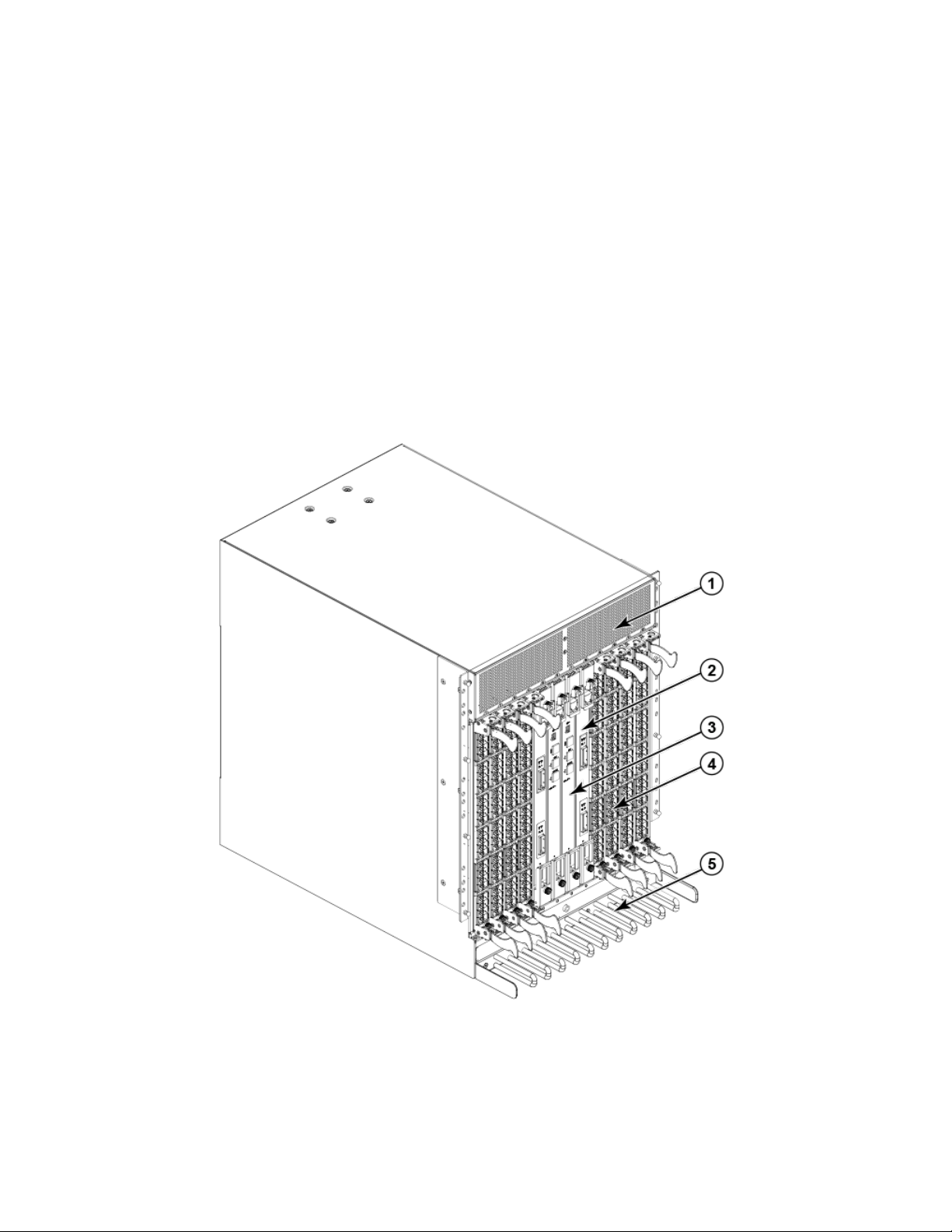
Port side of the Brocade DCX
NOTE
Airow in the Brocade DCX is from the nonport (noncable) side to the port (cable) side and out the exhaust
vent.
The following illustration displays a sample conguration of the port side of the Brocade DCX.
FIGURE 1 Port side of the Brocade DCX (sample conguration)
1. Exhaust Vent
2. Core switch blade (CR8)
3. Control processor blade (CP8)
Brocade DCX Backbone Hardware Installation Guide
53-1000685-24 17
Page 18
Brocade DCX blades
4. FC8-48 port blade
5. Cable management comb
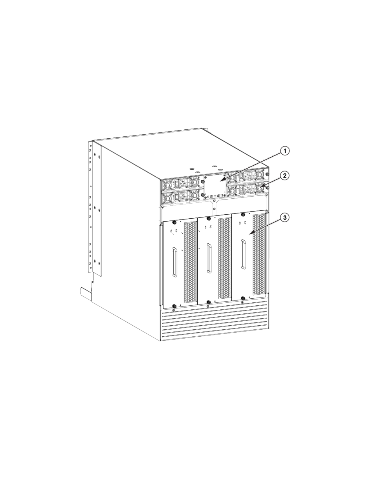
Nonport side of the Brocade DCX
The following illustration displays a sample conguration of the nonport side of the Brocade DCX.
FIGURE 2 Nonport side of the Brocade DCX (sample conguration)
1. WWN bezel (logo plate)
2. Power supply (4x)
3. Blower assembly (3x)
Brocade DCX blades
The following table summarizes the port, application, control processor, and core switch blades that are supported on the Brocade DCX.
18 53-1000685-24
Brocade DCX Backbone Hardware Installation Guide
Page 19

Brocade DCX blades
TABLE 1 Blades supported on Brocade DCX
Description Name Function
Brocade DCX control processor blade CP8 The CP8 blade contains the control plane for the
chassis. There are two CP8 blades for
redundancy. This control processor blade is
compatible with the Brocade DCX and Brocade
DCX-4S.
Brocade DCX core switch blade CR8 The CR8 blade contains the ASICs for switching
between port blades. Every port blade connects
to each core switch blade. There can be up to
512 total ports for port blades. Each core switch
blade connects to 128 backplane ports. Core
switch blades have additional front port
connectivity to connect multiple chassis and
backplane connections for the storage server
blade. This core switch blade is compatible only
with the Brocade DCX.
16-port 8-Gbps port blade FC8-16 A 16-port Brocade port blade supporting 1, 2,
4, and 8 Gbps port speeds. This port blade is
compatible with the Brocade 48000 Director,
Brocade DCX, and Brocade DCX-4S.
32-port 8-Gbps port blade FC8-32 A 32-port Brocade port blade supporting 1, 2,
4, and 8 Gbps port speeds. This port blade is
compatible with the Brocade 48000 Director,
Brocade DCX, and Brocade DCX-4S.
48-port 8-Gbps port blade FC8-48 A 48-port Brocade port blade supporting 1, 2,
4, and 8 Gbps port speeds. This port blade is
compatible with the Brocade 48000 Director,
Brocade DCX, and Brocade DCX-4S.
64-port 8-Gbps port blade FC8-64 A 64-port Brocade port blade supporting 2, 4,
and 8 Gbps port speeds. This port blade is
compatible with the Brocade DCX and Brocade
DCX-4S. This blade cannot be used in the same
chassis with an FCOE10-24 blade.
Storage encryption blade FS8-18 The FS8-18 blade enables data cryptographic
(encryption/decryption) and data-compression
capabilities. It has 16 Fibre Channel optical SFP
ports. This application blade is compatible with
the Brocade 48000 Director, Brocade DCX, and
Brocade DCX-4S.
FCIP extension blade FX8-24 The FX8-24 blade enables FCIP functionality
over existing IP infrastructure. It has 12 FC
ports, 10 GbE ports, and 2 10GbE ports
available. This application blade is compatible
with the Brocade DCX and Brocade DCX-4S.
Fibre Channel over Ethernet blade FCOE10-24 The FCOE10-24 blade enables FCoE
functionality over existing Ethernet infrastructure
utilizing CEE protocols. It has 24 10GbE ports
available. This application blade is compatible
with the Brocade DCX and Brocade
DCX-4S.This blade cannot be used in the same
chassis with an FC8-64 high density port blade
or any of the other application blades (FX8-24
or FS8-18).
Brocade DCX Backbone Hardware Installation Guide
53-1000685-24 19
Page 20

Chassis slots
Chassis slots
Chassis slots are numbered 1 through 12, from left to right when facing the port side of the Brocade DCX. Control processor blades
(CP8) can be installed only in slots 6 and 7. Core switch blades (CR8) can be installed only in slots 5 and 8. The rest of the slots ,1-4 and
9-12, can be lled with port, application, or encryption blades. Unused slots must be lled with blade ller panels to maintain adequate
cooling.
Port numbering
The Brocade DCX uses the following port numbering method (Port Numbering Template on page 149).
Port or application blade Port numbering Trunking port group numbering
FC8-16 port blade
FC8-32 port blade
FC8-48 port blade
FC8-64 port blade
FS8-18 blade
FX8-24 blade
FCOE10-24 blade
• 0 through 15 from bottom to top.
• 0 through 15 from bottom to top on the left set of
ports.
• 16 through 31 from bottom to top on the right set
of ports.
• 0 through 23 from bottom to top on the left set of
ports.
• 24 through 47 from bottom to top on the right set
of ports.
• 0 through 31 from bottom to top on the left set of
ports.
• 32 through 63 from bottom to top on the right set
of ports.
• FC ports: 0 through 15 from bottom to top.
• 10/100/1000 BaseT ports: GE0 and GE1 from
the bottom.
• FC ports: 0 through 11 in two vertical rows of six
ports starting from the bottom left and bottom right
in the lower group of 12 ports. Labeled as FC on
the front panel diagram.
• 10-GbE ports: 0 and 1 in the left-hand column just
above the FC ports. Labeled as 10GE on the front
panel diagram.
• 1-GbE ports: 0 through 9 in both columns above
the FC and 10GE ports. Labeled as GE on the
front panel diagram.
• 0 through 23 in two vertical rows from bottom left
to top right.
• 0-7, 8-15, 16-23, 24-31, 32-39, 40-47,
48-55, and 56-63.
Up to three FC trunking groups are permitted.
• Trunk group 0: FC ports 0, 1
• Trunk group 1: FC ports 6, 7
• Trunk group 2: FC ports 2, 3, 4, 5, 8, 9, 10,
11
High availability
The following features contribute to the Brocade DCX high-availability design:
• Redundant, hot-swappable blades and FRUs
• Enhanced data integrity on all data paths
• Fabric Shortest Path First (FSPF) rerouting around failed links
20 53-1000685-24
Brocade DCX Backbone Hardware Installation Guide
Page 21

Serviceability
• Integration with Simple Network Management Protocol (SNMP) managers
• Automatic control processor failover
• Nondisruptive "hot" software code loads and activation
• Easy conguration, save, and restore
• Hot-swappable World Wide Name (WWN) cards
The high-availability software architecture of the Brocade DCX provides a common framework for all applications that reside on the
system, allowing global and local states to be maintained through any component failure. High-availability elements consist of the High
Availability Manager, the heartbeat, the fault/health framework, the replicated database, initialization, and software upgrade.
The High Availability Manager controls access to the standby control processor, facilitates software upgrades, prevents extraneous
switchover activity, closes and ushes streams, provides ow control and message buering, and supports a centralized active and
standby state.
Reliability
The Brocade DCX uses the following error detection and correction mechanisms to ensure reliability of data:
• Error Detection and Fault Isolation (EDFI) mechanism, which checks for encoder errors and fault isolation, such as cyclic
redundancy checking (CRC), parity checking, checksum, and illegal address checking.
• Power-on self-test (POST).
• Dual control processors that enable hot, nondisruptive fast
• One serial port and two Ethernet ports (on each control processor) for management and for service. Oine control processor
diagnostics and remote diagnostics simplify troubleshooting. The standby control processor monitors diagnostics to ensure it is
operational, should a failover be necessary.
• Bus monitoring and control of blades and other eld-replaceable units (FRUs).
rmware upgrades.
Serviceability
The Brocade DCX provides the following features to enhance and ensure serviceability:
• Modular design with hot-swappable components
• Flash memory that stores two
• USB port on control processor blades for all tasks that formerly required an FTP/SCP server, including software and rmware
upgrades
• Nonvolatile random-access memory (NVRAM), containing the OEM serial number, Brocade serial number, revision information,
and part number information
• Background health-check daemon
• Memory scrubber, self test, and bus ping to determine if a bus is not functioning
• RASlog messages
• SMI-S compliant
• Watchdog timers
• Status LEDs
• Predictive diagnostics analysis through Fabric Watch
Brocade DCX Backbone Hardware Installation Guide
53-1000685-24 21
rmware images per control processor
Page 22

Software features
• SNMP (including version 3) integration with higher-layer managers
Software features
The Fabric OS allows any Fibre Channel-compliant device to attach to the switches as long as it conforms to the device login, name
service, and related Fibre Channel standards. Each operating environment requires that a Fibre Channel host bus adapter (HBA) be
available with a standards-compliant driver for correct interface to the fabric.
Fabric OS consists of a set of embedded applications running on top of an embedded Linux operating system kernel. These applications
include:
• Name server
• Alias server
• Zone server
• Simple Network Management Protocol (SNMP) agent
• SMI-S compliant API
• Syslog auditing
• RCS (Reliable Commit Service)
• NTP
• Tasks to manage address assignment, routing, link initialization, fabric initialization, link shutdown, Brocade DCX shutdown, and
the user interface
Security
The following table highlights some of the key security features available for the Brocade DCX and for other Brocade enterprise-class
products running Fabric OS 5.2.0 or later. For details, contact your Brocade DCX supplier and refer to the Brocade White Paper, "The
Growing Need for Security in Storage Area Networks".
TABLE 2 Brocade security features
Brocade Security Features Description
DH-CHAP Login banner
SSHv2 (using AES, 3DES, RSA) Monitoring of attempted security breaches (through audit logging)
HTTPS (using AES) Monitoring of attempted security breaches (through Fabric Watch Security
Class)
SNMPv3 Fibre Channel security policies: DCC and SCC
FC-SP Trusted Switch (FCS) for central security management
Secure RPC Management access controls (SNMPv3, Telnet, FTP, serial port, front
panel)
Secure le copy (SCP) Hardware-enforced zoning by WWN, domain/port ID, or both
Telnet disable Default zoning
Telnet timeout RSCN suppression and aggregation
IP lters (block listeners) Congurable RSCN suppression by port
Secure passwords (centralized control through RADIUS/CHAP) NTPv3 (to synchronize timestamps)
Up to 255 multiple user accounts (MUAs). Event auditing
Role-based access controls (RBACs) Change tracking
22 53-1000685-24
Brocade DCX Backbone Hardware Installation Guide
Page 23

Network manageability
TABLE 2 Brocade security features (continued)
Brocade Security Features Description
Administrative domains/Virtual fabrics Firmware change alerts in Fabric Manager
Boot PROM password reset Persistent port disable
Password hardening policies Persistent domain ID
Upfront login in Web Tools E_Port disable
Network manageability
The Brocade DCX has a single domain and is managed as a single element with the Data Center Fabric Manager (DCFM). The Brocade
DCX responds to its own IP address and appears as a separate entity to the Telnet protocol and SNMP.
All management interfaces, such as Telnet, Web Tools, standards-compliant SMI-S, and Management Server, support a "port N within
blade M" naming scheme.
The Brocade DCX supports SNMPv1 and SNMPv3. When SNMP devices send SNMP messages to a management console running
SAN management software, the information is stored in a management information base (MIB). Fabric OS v6.1.1_enc and later
supports the latest Fibre Alliance Fibre Channel Management (FCMGMT) and Storage Management Initiative (SMI) MIBs, which allow
common information necessary for management software to provide information to a SAN administrator. Refer to the Brocade Fabric
OS Administration Guide for additional MIB information.
Brocade DCX Backbone Hardware Installation Guide
53-1000685-24 23
Page 24

24 53-1000685-24
Brocade DCX Backbone Hardware Installation Guide
Page 25

Preparing for the Installation
• Installation and safety considerations........................................................................................................................................................25
• Time and items required for installation...................................................................................................................................................26
• Items included with the device.....................................................................................................................................................................27
Installation and safety considerations
NOTE
Read the safety notices before installation.
Read the following sections before preparing to install the device.
• Caution and Danger Notices on page 165.
• Brocade DCX Backbone Technical Specications on page 159, power supply specications section, and plan for meeting the
power supply standards based on your device conguration.
• Cable Management on page 47 and plan for cable management.
The following steps are required to ensure correct installation and operation:
1. Ensure that dedicated electrical branch circuits with the following characteristics are available:
• 200-240 VAC, 50-60 Hz (two branch circuits)
• 110-120 VAC, 50-60 Hz (up to four branch circuits)
• Two cables for 200-240 VAC service; up to four cables for 110-120 VAC service
• Power supply standards are met
• Protected by a circuit breaker in accordance with local electrical codes
• Supply circuit, line fusing, and wire size adequate to the electrical rating on the chassis nameplate
• Location close to the chassis and easily accessible
• Grounded outlets installed by a licensed electrician and compatible with the power cords
ATTENTION
To maximize fault tolerance, connect each power cord to a separate power source.
2. Plan for cable management before installing the chassis (Cable Management on page 47).
Cables can be managed in a variety of ways, such as by routing cables below the chassis, to either side of the chassis, through
cable channels on the sides of the cabinet, or by using patch panels.
Brocade DCX Backbone Hardware Installation Guide
53-1000685-24 25
Page 26

Time and items required for installation
3. Ensure that the following is available for conguration of the Brocade DCX:
• Workstation with an installed terminal emulator, such as HyperTerminal
• Serial cable (provided)
• Three Ethernet cables (including one spare)
• Access to an FTP server for backing up the switch conguration or collecting supportsave output data (optional)
• A Brocade USB stick for collecting supportsave output data (optional)
• SFPs and compatible cables
NOTE
For information about the SFP transceivers that are qualied for the Brocade Encryption Switch, go to http://
www.brocade.com/products/interop_and_compatibility.jsp.
4. Ensure that the air intake and exhaust vents have a minimum of 2 inches of airspace.
5. Ensure that the air temperature on the air intake side is less than 40 degrees Celsius (104 degrees Fahrenheit) during operation.
Time and items required for installation
The following table describes the main installation and setup tasks, the estimated time required for each, and the items required to
complete the task based on a fully populated Brocade DCX (512 Fibre Channel ports).
Congurations with fewer ports require less time.
These time estimates assume a prepared installation site and appropriate power and network connectivity.
TABLE 3 Installation tasks, time, and items required
Installation task Time estimate Items required
Site preparation and unpacking Brocade DCX 30 minutes 1/2-in. socket wrench (to remove pallet bolts).
#2 Phillips screwdriver(for cable management
comb).
Pallet jack.
Hydraulic lift or assisted lift, able to raise to a
minimum of 140 cm (55 in.), with a minimum
capacity of 113 kg (250 lb). The Brocade DCX
weighs 159.2 kg (351 lb) with eight FC8-64
port blades installed (512 ports).
Installing rack mount kit 30 minutes Refer to Mounting the Device on page 29 .
Mounting and securing Brocade DCX in rack 30 minutes
Installing power cables and powering on the
Brocade DCX
Establishing serial connection, logging on to
Brocade DCX, and conguring IP addresses
Installing an Ethernet cable, opening a Telnet
session, and conguring the Brocade DCX
domain ID, date and time, and additional system
parameters. Verify and back up conguration.
20 minutes Power cables.
20 minutes Serial cable (provided in the accessory kit).
Workstation computer with a serial port or
terminal server port and a terminal emulator
application (such as HyperTerminal).
Ethernet IP addresses for the Brocade DCX and
for both control processor blades: total three
addresses.
20 minutes Ethernet cabling (optional) for Telnet access.
Refer to the Brocade Fabric OS Administration
Guide.
26 53-1000685-24
Brocade DCX Backbone Hardware Installation Guide
Page 27

TABLE 3 Installation tasks, time, and items required (continued)
Installation task Time estimate Items required
Installing SFP, SFP+, mSFP, and XFP (10Gbps) optical transceivers as needed
Attaching ber optic cables, cable ties, and cable
guides
30 minutes SFP, SFP+, mSFP, and XFP (10-Gbps) optical
transceivers as needed.
2-3 hours Fiber optic cables, cable ties, and cable comb.
Items included with the device
The Brocade DCX ships with the following:
• Brocade DCX chassis, populated with:
– Control processor blades (CP8)
– Core switch blades (CR8)
– Port blades and application blades, and encryption blades (included based on customer specication)
– Blade slot ller panels (for slots not lled by a port, control processor, or core switch blade)
– WWN cards
– WWN bezel (logo plate)
– Power supplies
– Power supply ller panels (included if there are fewer than four power supplies)
– Blower assemblies
– Cable management comb
– Chassis door
• Accessory kit containing the following items:
– ESD grounding strap
– USB device
– RS-232 serial cable. The RS-232 cable has an adapter at one end that can be removed to provide an RJ-45-style
connector.
• 14U Rack Mount Kit with instructions (includes rear brackets and bottom support rails)
Items included with the device
Order the optical transceivers (SFP, SFP+, mSFP, and XFP) from Brocade. The Brocade DCX supports SWL, LWL, and ELWL
transceivers. The mSFPs are SWL transceivers only.
NOTE
For information about the SFP, SFP+, mSFP, and XFP transceivers that are qualied for the Brocade DCX, go to http://
www.brocade.com/products/interop_and_compatibility.jsp.
Brocade DCX Backbone Hardware Installation Guide
53-1000685-24 27
Page 28

28 53-1000685-24
Brocade DCX Backbone Hardware Installation Guide
Page 29

Mounting the Device
• Mounting precautions......................................................................................................................................................................................29
• Mounting options...............................................................................................................................................................................................30
• Unpacking, transporting, and installing the device.............................................................................................................................. 30
• Installing the 14U Rack Mount Kit for Four-Post Racks (XBR-DCX-0120 and XBR-DCX-0152) ............................ 31
• Installing the 14U Chassis Mid-Mount Rack Kit for Two-Post Racks (XBR-DCX-0121).................................................39
Mounting precautions
Ensure that the following amount of space is available in the rack.
NOTE
1U is equal to 4.45 cm (1.75 inches).
• 14 rack units (14U) high
• 61.29 cm (24.09 in.) deep
• 43.74 cm (17.22 in.) wide
The following general considerations for mounting the device.
• Review Installation and safety considerations on page 25 before mounting the device and ensure that all facility requirements
are met.
• The device can be installed facing either direction in a cabinet, if serviceability and cooling requirements are met.
• Plan to install the device with the nonport side facing the air-intake aisle. The device can be installed facing either direction, if
serviceability and cooling requirements are met.
• Ensure that the air intake and exhaust vents have a minimum of 5.1 cm (2 in.) of airspace.
• Ensure that the air temperature on the air intake side is less than 40°C (104°F) during operation.
• Use a hydraulic lift or assisted lift that can raise a minimum of 140 cm (55 in.), with a minimum capacity of 115 kg (254 lb).
Refer to Brocade DCX Backbone Technical Specications on page 159 for the weight of your device, fully populated with the
required blades.
CAUTION
Do not use the port cover tabs to lift the module. They are not designed to support the weight of the module, which can fall
and be damaged.
CAUTION
Make sure the airow around the front, and back of the device is not
restricted.
DANGER
Mount the devices you install in a rack as low as possible. Place the heaviest device at the bottom and progressively place
lighter devices above.
DANGER
Use safe lifting practices when moving the product.
Brocade DCX Backbone Hardware Installation Guide
53-1000685-24 29
Page 30

Mounting options
CAUTION
To prevent damage to the chassis and components, never attempt to lift the chassis using the fan or power supply handles.
These handles were not designed to support the weight of the chassis.
CAUTION
Never leave tools inside the chassis.
DANGER
Make sure the rack housing the device is adequately secured to prevent it from becoming unstable or falling over.
Mounting options
This device can be installed as a standalone unit on a
post telecommunications (TELCO)equipment rack.
• In a four-post 19 in. (48.3 cm) EIA rack:
– Use the 14U rack mount kit for four-post racks (XBR-DCX-0120), which contains shelf brackets that telescope from 27 in.
(68.58 cm) to 31 in. (78.74 cm) to t the majority of racks.
– Use the 14U rack mount kit for four-post racks (XBR-DCX-0152), which contains 22 in. (55.88 cm) xed shelf brackets
designed for specic racks.
– Refer to Installing the 14U Rack Mount Kit for Four-Post Racks (XBR-DCX-0120 and XBR-DCX-0152) on page 31 for
instructions.
• In a two-post Telco rack:
– Use the 14U mid-mount rack kit for two-post racks (XBR-DCX-0121).
– Refer to Installing the 14U Chassis Mid-Mount Rack Kit for Two-Post Racks (XBR-DCX-0121) on page 39 for
instructions.
NOTE
Review the Installation and safety considerations on page 25 before mounting the device and ensure that all facility
requirements are met.
NOTE
The preceding rack mount kits are supported for this device at the publication date of this Hardware Installation Guide. For
current support information, contact your Brocade representative.
at surface or mounted a 19-inch Electronic Industries Association (EIA) or two-
Unpacking, transporting, and installing the device
DANGER
Use safe lifting practices when moving the product.
DANGER
A fully populated Brocade DCX (eight FC8-64 port cards, 512 ports) weighs approximately 159.2 kg (351 lbs) and
requires a hydraulic or assisted lift to install it.
30 53-1000685-24
Brocade DCX Backbone Hardware Installation Guide
Page 31

Installing the 14U Rack Mount Kit for Four-Post Racks (XBR-DCX-0120 and XBR-DCX-0152)
Use the following steps to unpack, transport, and install the device.
1. Unpack and install the Brocade DCX.
a) Cut the bands that encircle the packaging.
b) Remove the lid and the kits and foam from the top of the chassis.
c) Lift the cardboard box o the chassis and remove the plastic bag from around the chassis. Save the packing materials for
use when returning the old chassis.
d) Leave the chassis on top of the plastic shipping tray if the chassis must be transported to the installation location.
NOTE
The Brocade DCX packaging does not incorporate a wood pallet and pallet brackets. The chassis sits on top of a
plastic shipping tray.
2. Use a pallet jack or other assisted lift to transport the new chassis to the installation area. Doorways must be wider than 91 cm
(36 in.) to accommodate the chassis.
3. Remove the 14U Rack Mount Kit, accessory kit, packing foam, and antistatic plastic from the chassis and set aside.
4. Install the rack mount kit in the rack using appropriate instructions in this Hardware Installation Guide.
5. Remove the chassis door from the Brocade DCX.
6. Remove the cable management comb.
7. Use a lift to raise the chassis to the correct level. Follow the instructions provided by the rack kit manufacturer.
8. If applicable, lock the wheels of the lift.
9. Gently slide the chassis onto the nal installation surface, ensuring that it remains supported during the transfer.
10. Ensure that the chassis is oriented so that the nonport side has access to intake air (cool).
11. Reinstall the cable management comb.
12. If ICL cables will not be used, ensure that the ICL sockets in the core switch blades have EMI plugs inserted.
13. Reinstall the chassis door.
Installing the 14U Rack Mount Kit for Four-Post
Racks (XBR-DCX-0120 and XBR-DCX-0152)
Use the following instructions to install a modular device in a 19-in. (48.3 cm) EIA rack using the 14U Rack Mount Kit for Four-Post
Racks (XBR-DCX-0120 and XBR-DCX-0152).
Two rack-mount kits are available.
• XBR-DCX-0120 - Contains shelf brackets that telescope from 27 in. (68.58 cm) to 31 in. (78.74 cm) to
racks.
• XBR-DCX-0152 - Contains 22 in. (55.88 cm) xed shelf brackets that adjust to 27 in. (68.58 cm).
Observe the following when mounting this device:
• Use Electronic Industries Association (EIA) standard racks. Ensure that the space in the 19-in. (48.3 cm) EIA rack is 14U high.
• Verify that the additional weight of the chassis does not exceed the weight limits of the rack.
• Before mounting your device, review any specic installation and facility requirements in this Hardware Installation Guide.
• Hardware devices illustrated in these procedures are only for reference and may not depict the device you are installing into the
rack.
Brocade DCX Backbone Hardware Installation Guide
53-1000685-24 31
t the majority of
Page 32

Installing the 14U Rack Mount Kit for Four-Post Racks (XBR-DCX-0120 and XBR-DCX-0152)
Time and items required
Allow approximately one hour to unpack and install a device in a rack.
The following tools are required when installing the 14U Rack Mount Kit for Four-Post Rack:
• Torque screwdriver with #2 Phillips screwdriver tip
• Slotted (at blade) screwdriver
• Hydraulic or assisted lift with a minimum raise of 140 cm (55 in.) and a minimum capacity of 113 kg (250 lb)
Parts list
The following table lists 14U Rack Mount Kit parts and quantities for dierent installations. Refer to the illustration following the table to
identify these parts.
TABLE 4 14U rack mount kit parts and quantities
Description Installation Quantity
Left rack mount shelf bracket (rail brackets may dier from ones shown in illustration) All 1
Right rack mount shelf bracket (rail brackets may dier from ones shown in illustration) All 1
10-32 x 5/8 in. (1.58 cm) panhead Phillips screw and washer (torque to 32 in-lb, [37 cm-
kg])
10-32 clip nut For rack rails with round holes 6
1/4-20 x 1/2 in. (1.27 cm) panhead Phillips screw with lock washer (torque to 80 in-lb [92
cm-kg])
10-32 retainer nut For rack rails with square holes 6
1/4-20 x 1/2 in. (1.27 cm) panhead Phillips screw with thread locker (torque to 80 in-lb [92
cm-kg])
3/8 in. (0.953 cm) alignment washer For rack rails with square holes 16
All 6
For rack rails with round holes 16
For rack rails with square holes 16
NOTE
Depending on the device and installation, not all the parts may be used on the device type.
32 53-1000685-24
Brocade DCX Backbone Hardware Installation Guide
Page 33

FIGURE 3 14U rack kit parts
Installing the 14U Rack Mount Kit for Four-Post Racks (XBR-DCX-0120 and XBR-DCX-0152)
1. Left rack mount shelf bracket
2. Right rack mount shelf bracket
3. 10-32 x 5/8 in. (1.58 cm) panhead Phillips screw and washer
4. 10-32 clip nut for cabinets that have rails with round holes
5. 1/4-20 x 1/2 in. (1.27 cm) panhead Phillips screw with lock washer for
cabinets that have rails with round holes
6. 10-32 retainer nut for cabinets that have rails with square holes
7. 1/4-20 x 1/2 in. (1.27 cm) panhead Phillips screw with thread locker for
cabinets that have rails with square holes
8. 3/8 in. (0.953 cm) alignment washer for cabinets that have rails with
square holes
Parts list – NEBS kit
The following table lists the parts supplied in the XBR-SLX9850-8-NEBS-KIT to help direct airow away from the rack area. This kit is
only supported for specic devices, and may not apply to the device that you are installing.
NOTE
Depending on the device and installation, not all of the parts may be used.
Verify that the items listed in the following gure are included in the NEBS kit.
Brocade DCX Backbone Hardware Installation Guide
53-1000685-24 33
Page 34

Installing the 14U Rack Mount Kit for Four-Post Racks (XBR-DCX-0120 and XBR-DCX-0152)
FIGURE 4 NEBS kit parts list
1. Left cable comb assembly (1)
2. Right cable comb assembly (1)
3. Air lter (1)
4. Chassis door (1)
5. Velcro strap (8)
6. Screw, 10-32 x .63-in., square cone washer (10)
7. Screw, 8-32 x .312 in., athead (20)
8. Nut retainer (6)
Assembling the rack hardware
Attach the left and right rack mount shelf brackets to the rack rails.
NOTE
If cables are to be routed down through the cable management comb, allow space below the brackets for cable management
1. Locate the shelf brackets in the device.
34 53-1000685-24
Brocade DCX Backbone Hardware Installation Guide
Page 35

Installing the 14U Rack Mount Kit for Four-Post Racks (XBR-DCX-0120 and XBR-DCX-0152)
2. Locate and loosen the screws on the adjustable ends of the brackets (see the following gure) to allow for adjustment to rack
depth.
FIGURE 5 Left and right shelf brackets installed on rails
1. Left rack mount shelf bracket
2. Right rack mount shelf bracket
3. 1/4-20 x 1/2 in. (1.27 cm) panhead Phillips screw with lock
washer for rails with round holes (4 on each end of each
bracket, 16 total)
4. 3/8 in. (0.953 cm) alignment washer for rails with square
holes (4 on each end of each bracket, 16 total)
5. 1/4-20 x 1/2 in. (1.27 cm) panhead Phillips screw with
thread locker for rails with square holes (4 on each end of each
bracket, 16 total)
6. Adjustable ends of shelf brackets
7. Intake air direction
8. Exhaust air direction
CAUTION
Use the screws specied in the procedure. Using longer screws can damage the
device.
Brocade DCX Backbone Hardware Installation Guide
53-1000685-24 35
Page 36

Installing the 14U Rack Mount Kit for Four-Post Racks (XBR-DCX-0120 and XBR-DCX-0152)
3. Position the shelf brackets with the adjustable ends on the intake air aisle side of the rack (see the previous gure).
• For rails with round holes:
– Position the left and right rack mount shelf brackets and attach them to the rack rails. Use eight screws with lock
washers per bracket (four on each end). Tighten the screws to a torque of 80 in-lb (92 cm-kg).
• For rails with square holes:
– Position the left and right rack mount shelf brackets and attach them to the rack rails. Use eight screws and alignment
washers per bracket (four on each end). Tighten the screws to a torque of 80 in-lb (92 cm-kg).
FIGURE 6 Nut and screw locations for mounting the device
1. 10-32 clip nuts (for round holes)
2. Rail
3. 10-32 retainer nut (for square holes)
4. Rail
5. Top screws in shelf bracket
6. Bottom screws in shelf bracket
7. Left rack mount shelf bracket
8. Right rack mount shelf bracket
9. Hole 1
NOTE
Standard EIA rails have holes in sets of three; spaces between the holes are 5/8 in., 5/8 in., and 1/2 in. (1.58 cm,
1.58 cm, and 1.27 cm).
4. Tighten the adjusting screws on the sliding portion of the rack mount shelf brackets to a torque of 32 in-lb (37 cm-kg).
36 53-1000685-24
Brocade DCX Backbone Hardware Installation Guide
Page 37

Installing the 14U Rack Mount Kit for Four-Post Racks (XBR-DCX-0120 and XBR-DCX-0152)
5. Attach the clip nuts (for rails with round holes) or retainer nuts (for rails with square holes) to the vertical rails on the exhaust aisle
side of the rack (see the previous gure). These clip nuts are used for securing the port side of the device to the rack rails using
10-32 x 5/8 inch screws. Use three clips on each rail. Place the clips in optimum locations for securing the device to the rails.
NOTE
Do not align the clip or retainer nuts with the top or bottom holes of the mounting bracket because the screw heads will
interfere with the door.
Installing the device in the rack
Use the following procedure to install the device in the rack.
DANGER
Use safe lifting practices when moving the product.
1. Ensure that the door, if installed, is removed from the port side of the device. For instructions, refer to instructions for removing
and replacing the device door in the device installation guide.
2. Use a lift to raise the device to the level of the shelf brackets.
3. Move the lift as close as possible to the rack, with the air-intake side of the device facing the front of the rack (see the following
gure).
4. If applicable, lock the wheels of the lift.
Brocade DCX Backbone Hardware Installation Guide
53-1000685-24 37
Page 38

Installing the 14U Rack Mount Kit for Four-Post Racks (XBR-DCX-0120 and XBR-DCX-0152)
5. Gently slide the device onto the shelf brackets, ensuring that it remains supported during the transfer.
FIGURE 7 Positioning the device for installation in a rack
1. Rack 2. Nonport side of device
38 53-1000685-24
Brocade DCX Backbone Hardware Installation Guide
Page 39

Installing the 14U Chassis Mid-Mount Rack Kit for Two-Post Racks (XBR-DCX-0121)
6. Fasten the port side of the device to the rack rails. Use three 10-32 x 5/8 inch (1.58 cm) screws per rail. Tighten the screws to
a torque of 32 in-lb (37 cm-kg). Refer to Figure 8.
NOTE
Do not use the top or bottom holes of the mounting bracket because the screw heads will interfere with the door.
FIGURE 8 Attaching port side of device to rack rails
1. 10-32 x 5/8 in. (1.58 cm) panhead Phillips screw with washer
7. Reinstall the device door if removed from your device. For instructions, refer to the door removal and replacement procedures in
your device installation guide.
Installing the 14U Chassis Mid-Mount Rack Kit for
Two-Post Racks (XBR-DCX-0121)
Use the following instructions to install a Brocade modular device in a telecommunications (Telco) rack, using the 14U Chassis MidMount Rack Kit for Two-Post Racks (XBR-DCX-0121).
Brocade DCX Backbone Hardware Installation Guide
53-1000685-24 39
Page 40

Installing the 14U Chassis Mid-Mount Rack Kit for Two-Post Racks (XBR-DCX-0121)
Observe the following when mounting this device:
• The kit is compatible with rack rails that are either 3 inches or 5 inches wide (adapters are provided for 3-in. rails).
• Before mounting your device, review any specic installation and facility requirements in this Hardware Installation Guide.
• Hardware devices illustrated in these procedures are only for reference and may not depict the device you are installing into the
rack.
Time and Items required
Allow approximately one hour to unpack and install a chassis in a rack.
The following tools are required when installing the 14U Chassis Mid-Mount Rack Kit for Two-Post Racks.
• Torque wrench with #2 Phillips screwdriver tip
• Flathead screwdriver
• Hydraulic or assisted lift with a minimum raise of 140 cm (55 in.) and a minimum capacity of 113 kg (250 lbs).
Parts list
The following parts are provided with the 14U Chassis Mid-Mount Rack Kit for Two-Post Racks (XBR-DCX-0121).
40 53-1000685-24
Brocade DCX Backbone Hardware Installation Guide
Page 41

FIGURE 9 Rack kit parts
Installing the 14U Chassis Mid-Mount Rack Kit for Two-Post Racks (XBR-DCX-0121)
1. Tray, front, mid-mount, chassis
2. Tray, rear, mid-mount, chassis
3. Adapter, rear, mid-mount, right
4. Adapter, rear, mid-mount, left
5. Screw, 10-32 x 3/8”, pan head Phillips, ST, zinc (requires a torque of 32
inch-pounds)
NOTE
Not all parts may be used with certain installations depending on the device type.
Assembling the rack hardware
Perform the following steps to assemble the rack hardware.
1. Attach the rear tray (with or without adapter, as required) to both rack rails. Orient the tray (refer the following
screws (Item E) for each rail.
2. Attach the front tray to both rack rails. Orient the tray (Figure 11) and use nine screws (Item E) for each rail.
Brocade DCX Backbone Hardware Installation Guide
53-1000685-24 41
gure) and use nine
Page 42

Installing the 14U Chassis Mid-Mount Rack Kit for Two-Post Racks (XBR-DCX-0121)
3. Verify that the rear edge of the front tray is seated into the front edge of the rear tray.
FIGURE 10 Attaching the rear tray to the rack rails
2. Tray, rear, mid-mount, chassis
3. Adapter, rear, mid-mount, right
4. Adapter, rear, mid-mount, left
5. Screws
42 53-1000685-24
Brocade DCX Backbone Hardware Installation Guide
Page 43

FIGURE 11 Attaching the front tray to the rack rails
Installing the 14U Chassis Mid-Mount Rack Kit for Two-Post Racks (XBR-DCX-0121)
1. Tray, front, mid-mount, chassis
5. Screws
Installing the device in the rack
DANGER
Use safe lifting practices when moving the product.
NOTE
A fully populated device requires a hydraulic or assisted lift to install into a rack.
Brocade DCX Backbone Hardware Installation Guide
53-1000685-24 43
Page 44

Installing the 14U Chassis Mid-Mount Rack Kit for Two-Post Racks (XBR-DCX-0121)
Perform the following steps to load the device into the mid-mount trays.
1. Ensure that the door is removed from the port side of the device. For instructions, refer to the door removal and replacement
procedures in your device installation guide.
2. Orient the device (refer the following gure) and use a hydraulic lift to raise it to the level of the trays.
3. If applicable, lock the wheels of the lift.
4. Slide the device into the trays until the front edge of the device is seated against the front tray.
FIGURE 12 Placing the device in the trays
1. Tray, front, mid-mount, chassis 2. Tray, rear, mid-mount, chassis
5. Use three screws (Item 5) to attach each side of the rear tray to the device (refer the following gure).
NOTE
The screw holes in the device walls have pem nuts on the inside surface.
44 53-1000685-24
Brocade DCX Backbone Hardware Installation Guide
Page 45

Installing the 14U Chassis Mid-Mount Rack Kit for Two-Post Racks (XBR-DCX-0121)
6. Use four screws (Item 5) to attach each side of the front tray to the device
7. Use six screws (Item 5) to attach the lip on each side of the front tray to the lip on the front of the device.
NOTE
Do not use the top or bottom holes of the Brocade mounting bracket because the door will interfere with the screw
heads.
FIGURE 13 Attaching trays to the device
8. Reinstall the device door. For instructions, refer to the door removal and installation instructions in your device installation guide.
Brocade DCX Backbone Hardware Installation Guide
53-1000685-24 45
Page 46

46 53-1000685-24
Brocade DCX Backbone Hardware Installation Guide
Page 47

Cable Management
• Requirements and precautions.................................................................................................................................................................... 47
• Qualied cables for the FC8-64 port blade.......................................................................................................................................... 48
• Installing ICL cables (optional)......................................................................................................................................................................49
Requirements and precautions
The cable management comb is attached to the chassis under the chassis door and allows for simple cable management. The comb can
be installed without service disruption.
Route the cables down in front of the blades to keep LEDs visible. Leave at least one meter of slack for each
room to remove and replace blades.
ATTENTION
Do not route the cables in front of the air exhaust vent, which is located at the top of the port side of the chassis.
CAUTION
Before plugging a cable into any port, be sure to discharge the voltage stored on the cable by touching the electrical
contacts to ground surface.
The FC8-64 high density port blade cannot use the standard LC cables because the pitch between optics in the new mSFP transceiver
is smaller than in standard SFPs. Patch cables and panels can be used to attach standard size cabling to the blade if necessary. The
following gure illustrates the mSFP to SFP patch cable. See "Best Practices Guide: High Density Cable Management Solutions"
(available at http://www.brocade.com ) for cable management guidelines for high-density port solutions, cable and patch panel part
numbers.
FIGURE 14 Cable design for the mSFP patch cables for the FC8-64 high density port blade
ber optic cable to provide
1. mini-SFP connector
2. Duplex clip (black)
3. 1.6 mm cable
4. SFP connector
Please note that the duplex clip on the mSFP end of the cable is black for easier recognition. See Qualied cables for the FC8-64 port
blade on page 48 for a listing of the qualied mSFP optical cables for the FC8-64 port blade.
If ISL Trunking is in use, group the cables by trunking group. The ports are color-coded to indicate which ports can be used in the same
ISL Trunking group: eight ports marked with solid black ovals alternate with eight ports marked with oval outlines.
Brocade DCX Backbone Hardware Installation Guide
53-1000685-24 47
Page 48

Qualied cables for the FC8-64 port blade
Qualied cables for the FC8-64 port blade
The following table lists the third party cables that have been qualied for use with the mSFP transceivers in the FC8-64 high density
port blade.
TABLE 5 Qualied cables for mSFP connections for the FC8-64 high density port blade
Description Length Corning part number Molex part number Amphenol part number
Patch cables - mSFP to LC S50502S5120XXXM (XXX
= length)
mSFP LC - standard LC,
duplex, multi-mode, OM3,
50/125
mSFP LC - standard LC,
duplex, multi-mode, OM3,
50/125
mSFP LC - standard LC,
duplex, multi-mode, OM3,
50/125
mSFP LC - standard LC,
duplex, multi-mode, OM3,
50/125
mSFP LC - standard LC,
duplex, multi-mode, OM3,
50/125
Patch cables - mSFP to
mSFP
mSFP LC - mSFP LC,
duplex, multi-mode, OM3,
50/125
mSFP LC - mSFP LC,
duplex, multi-mode, OM3,
50/125
mSFP LC - mSFP LC,
duplex, multi-mode, OM3,
50/125
mSFP LC - mSFP LC,
duplex, multi-mode, OM3,
50/125
mSFP LC - mSFP LC,
duplex, multi-mode, OM3,
50/125
1 m S50502S5120001M 106273-0525 943-99865-10001
2 m S50502S5120002M 106273-0526 943-99865-10002
3 m S50502S5120003M 106273-0527 943-99865-10003
5 m S50502S5120005M 106273-0528 943-99865-10005
10 m S50502S5120010M 106273-0529 943-99865-10010
S5S502S5120XXXM (XXX
= length)
1 m S5S502S5120001M 106273-0560 943-99866-10001
2 m S5S502S5120002M 106273-0561 943-99866-10002
3 m S5S502S5120003M 106273-0562 943-99866-10003
5 m S5S502S5120005M 106273-0563 943-99866-10005
10 m S5S502S5120010M 106273-0564 943-99866-10010
943-99865-1XXXX (XXXX
= length)
943-99866-1XXXX (XXXX
= length)
Trunk cables - mSFP to
MTP
mSFP LC - MTP-female,
12 ber, 12" breakout,
OM3, 50/125
mSFP LC - MTP-female,
12 ber, 6" breakout, OM3,
50/125
mSFP LC - MTP-female,
24 ber, 12" breakout,
OM3, 50/125
48 53-1000685-24
2m 106272-0327
2m 106272-0328
tbd
H93S5TE9-BMU-XXXM
(XXX = length)
943-99867-1XXXX (XXXX
= length)
Brocade DCX Backbone Hardware Installation Guide
Page 49

Installing ICL cables (optional)
TABLE 5 Qualied cables for mSFP connections for the FC8-64 high density port blade (continued)
Description Length Corning part number Molex part number Amphenol part number
Bag of clips (quantity 64) TRIGGER-BP-NP n/a n/a
Installing ICL cables (optional)
Go to Removal and replacement of the inter-chassis link (ICL) cables on page 115 for the procedure to install the ICL cables
Brocade DCX Backbone Hardware Installation Guide
53-1000685-24 49
Page 50

50 53-1000685-24
Brocade DCX Backbone Hardware Installation Guide
Page 51

Logging In and Conguring the DCX
Backbone
• Items required..................................................................................................................................................................................................... 51
• Providing power to the DCX Backbone...................................................................................................................................................52
• Conguring the Brocade DCX......................................................................................................................................................................52
• Establishing a serial connection and logging on to the Brocade DCX........................................................................................53
• Logging in to the serial console port.........................................................................................................................................................54
• Conguring the IP addresses.......................................................................................................................................................................54
• Logging o the serial console port and disconnecting the serial cable......................................................................................56
• Connecting an Ethernet cable and opening a Telnet session......................................................................................................... 56
• Customizing a switch name.......................................................................................................................................................................... 56
• Customizing a chassis name........................................................................................................................................................................57
• Setting the domain ID......................................................................................................................................................................................57
• Setting the date and time............................................................................................................................................................................... 57
• Verifying the PID mode and connecting to the fabric........................................................................................................................ 59
• Software licenses...............................................................................................................................................................................................59
• Installing transceivers and attaching cables............................................................................................................................................60
• Managing cables................................................................................................................................................................................................60
• Verifying correct operation and backing up the
• Powering o the Brocade DCX....................................................................................................................................................................62
conguration........................................................................................................ 61
Items required
The following items are required for initial setup and
• The device, mounted and installed with the required blades, FRUs, transceivers, and cables and is connected to a power source.
• A workstation computer with an installed terminal emulator application, such as HyperTerminal for Windows.
• Unused IP addresses with corresponding subnet mask and gateway addresses for the device and for both management
modules (total of three addresses).
• A serial cable (provided) with an RJ-45 connector.
• An RJ-45 to DB-9 adapter.
• Three Ethernet cables (including one spare)
• Access to an FTP server or USB device for backing up (uploading) or downloading the device conguration or collecting
supportsave output data (optional).
• A Brocade USB drive for collecting supportsave output data (optional)
verication of the device:
Brocade DCX Backbone Hardware Installation Guide
53-1000685-24 51
Page 52

Providing power to the DCX Backbone
Providing power to the DCX Backbone
ATTENTION
Use the supplied power cords. Ensure the facility power receptacle is the correct type, supplies the required voltage, and is
properly grounded. (D004)
1. Connect the AC power cords to the power supply assemblies. One to four power cords are required depending on electrical
service.
2. Connect the power cords to a power source with voltage of 200 to 240 VAC, 47 to 63 Hz (normally two power cords or as
many as four) or to a power source with voltage of 110 to 120 VAC, 47 to 63 Hz (two to four power cords).
ATTENTION
Use of the high-voltage line (200 to 240 VAC) is highly recommended because of better power-conversion
eciency.
3. Turn the AC power switches on the power supplies to ON. The AC power switches light green when switched on and power is
supplied.
4. The Brocade DCX performs a power-on self-test (POST) each time it is powered on. POST takes approximately 10 minutes
and is complete when the indicator light activity displays the operational state. For information about LED patterns, see
Monitoring System Components on page 63.
You can bypass POST by using the fastBoot command. You can also disable POST for successive reboots on the Brocade
DCX using the diagDisablePost command.
ATTENTION
Do not connect the switch to the network until the IP addresses are
congured.
Conguring the Brocade DCX
The Brocade DCX must be
through the active CP blade. The Brocade DCX conguration includes the following parameters:
• IP address and subnet mask for the chassis
• IP addresses, host names, subnet masks, and gateway addresses for both CP blades
• Switch name
• Domain ID for the Brocade DCX (optional)
• WWN for the Brocade DCX
The Brocade DCX WWN is initially set by the factory to match the license ID (which is based on the chassis serial number).
The conguration information is mirrored to the standby CP blade, which allows the current conguration to remain available even if the
active CP blade fails. The conguration information for the Brocade DCX is stored in the WWN cards and the ash memory of the CP
blades. The conguration can be backed up to a workstation (uploaded) and then downloaded to the active CP blade if necessary.
congured before it is connected to the fabric, and all of the conguration commands must be entered
NOTE
If the Brocade FS8-18 encryption blade is installed, refer to the Fabric OS Encryption Administrator’s Guide for the procedures
to congure the encryption functions
The following gure illustrates the ow of the basic conguration tasks.
52 53-1000685-24
Brocade DCX Backbone Hardware Installation Guide
Page 53

FIGURE 15 Conguration tasks
Establishing a serial connection and logging on to the Brocade DCX
Establishing a serial connection and logging on to the
Brocade DCX
1. Verify that the Brocade DCX is powered on and that POST is complete by verifying that all power LED indicators on the port,
control processor, and core switch blades display a steady green light.
2. Remove the shipping cap from the CONSOLE port on the active CP. Use the serial cable provided with the Brocade DCX to
connect the CONSOLE port on the active CP to a computer workstation. The active CP blade is indicated by an illuminated
(blue) LED.
ATTENTION
The CONSOLE port is intended primarily for the initial setting of the IP address and for service purposes.
3. Access the Brocade DCX using a terminal emulator application (such as HyperTerminal in a Windows environment or tip in a
UNIX environment).
4. Disable any serial communication programs running on the workstation (such as synchronization programs).
Brocade DCX Backbone Hardware Installation Guide
53-1000685-24 53
Page 54

Logging in to the serial console port
5. Open the terminal emulator application and congure as follows:
For most MS Windows systems:
Bits per second: 9600Databits: 8Parity: NoneStop bits: 1Flow control: None
NOTE
Flow control is not supported on the serial consoles when attached to remote terminal servers and must be disabled
on the customer-side remote terminal server and the host-side clients.
In a UNIX environment, type the following string at the prompt:
tip /dev/ttyb -9600
If ttyb is already in use, use ttya instead and enter the following string at the prompt:
tip /dev/ttya -9600
When the terminal emulator application stops reporting information, press Enter . You receive the following login prompt:
CP0 Console Login:
Logging in to the serial console port
To log in to the Brocade DCX through the serial connection, follow these steps.
1. Log in to the Brocade DCX as admin. The default password is password. You are prompted to change the default passwords at
initial login. Make sure to write down the new passwords and keep this information in a secure location.
Fabric OS (swDir)
swDir login: admin
Password:
Please change your passwords now.
Use Control-C to exit or press 'Enter' key to proceed.
Password was not changed. Will prompt again at next login
until password is changed.
swDir:admin>
2. (Optional) Modify passwords. To skip modifying the password, press Ctrl-C. For more information on passwords, refer to the
Brocade Fabric OS Administration Guide.
NOTE
Passwords can be 8 to 40 characters long. They must begin with an alphabetic character. They can include numeric
characters, the dot (.), and the underscore (_) only. Passwords are case-sensitive, and they are not displayed when you
enter them on the command line.
Conguring the IP addresses
The Brocade DCX requires three IP addresses, which are
CP blades (CP0 and CP1) and for the chassis management IP (shown as SWITCH under the ipAddrShow command) in the Brocade
DCX.
54 53-1000685-24
congured using the ipAddrSet command. IP addresses are required for both
Brocade DCX Backbone Hardware Installation Guide
Page 55

Conguring the IP addresses
NOTE
The default IP addresses and host names for the Brocade DCX are:- 10.77.77.75 / CP0 (the CP blade in slot 6 at the time of
conguration)- 10.77.77.74 / CP1 (the CP blade in slot 7 at the time of conguration)
ATTENTION
Resetting an IP address while the Brocade DCX has active IP trac or has management and monitoring tools running, such as
DCFM, Fabric Watch, and SNMP, can cause trac to be interrupted or stopped.
1. Log in to the active CP as admin using the serial cable connection.
2. Set up the Brocade DCX IP address by entering the ipaddrset -chassis command:
swDir:admin> ipAddrSet -chassis
Enter the information at the prompts. Specify the -chassis IP address. The -sw 0 IP address is no longer valid on this chassis.
NOTE
The addresses 10.0.0.0 through 10.0.0.255 are reserved and used internally by the Brocade DCX. External IP
addresses must not use these addresses.
3. Set up the CP0 IP address by entering the ipaddrset -cp 0 command:
swDir:admin> ipAddrSet -cp 0
Enter the information at the prompts.
4. Set up the CP1 IP address by entering the ipaddrset -cp 1 command:
swDir:admin> ipAddrSet -cp 1
Enter the information at the prompts.
This is a sample IP
swDir:admin> ipaddrset -chassis
Ethernet IP Address [0.0.0.0]: 123.123.123.120
Ethernet Subnetmask [0.0.0.0]: 123.123.123.123
Fibre Channel IP Address [0.0.0.0]:
Fibre Channel Subnetmask [0.0.0.0]:
Issuing gratuitous ARP...Done.
Committing configuration...Done.
swDir:admin>
ipaddrset -cp 0
Host Name [cp0]:
Ethernet IP Address [10.77.77.75]: 123.123.123.121
Ethernet Subnetmask [0.0.0.0
]: 123.123.123.123
Gateway IP Address [0.0.0.0
]: 123.123.123.124
IP address is being changed...Done.
Committing configuration...Done.
swDir:admin> ipaddrset -cp 1
Host Name [cp1]:
Ethernet IP Address [10.77.77.74]: 123.123.123.122
Ethernet Subnetmask [0.0.0.0]: 123.123.123.123
Gateway IP Address [0.0.0.0]: 123.123.123.124
IP address of remote CP is being changed...Done.
Committing configuration...Done.
conguration:
swDir:admin> reboot
5. Type reboot to reboot the Brocade DCX.
Brocade DCX Backbone Hardware Installation Guide
53-1000685-24 55
Page 56

Logging o the serial console port and disconnecting the serial cable
Logging o the serial console port and disconnecting
the serial cable
You can use the serial port to monitor error messages through the serial connection. If the serial port is no longer required, use the logout
command to log out of the serial console, remove the serial cable, and replace the plug in the serial port.
Connecting an Ethernet cable and opening a Telnet session
NOTE
Connecting the CP blades to a private network/VLAN is recommended.
After using a serial connection to congure the IP addresses for the Brocade DCX, you can connect the active CP blade to the local area
network (LAN).
By establishing an Ethernet connection, you can complete the Brocade DCX conguration using a serial session, Telnet, or management
applications, such as Web Tools or DCFM.To create an Ethernet connection to the Brocade DCX, follow these steps.
1. Remove the shipping plug from the Ethernet port on the active CP blade.
2. Insert one end of an Ethernet cable into the Ethernet port.
3. Connect the other end to an Ethernet 10/100/1000 BaseT LAN.
The Brocade DCX can be accessed through a remote connection using any of the management tools, such as Telnet, Web
Tools, or DCFM.
4. To complete any additional Brocade DCX
Telnet, using the admin login. The default password is password.
conguration procedures through a Telnet session, log in to the Brocade DCX by
Customizing a switch name
The switch name of the Brocade DCX can be up to 30 characters long as of Fabric OS release 6.3.0; can include letters, numbers, and
underscore characters; and must begin with a letter. Fabric OS releases earlier than 6.3.0 require switch names of 15 characters or less.
NOTE
Changing the name causes a domain address format RSCN to be issued.
1. Type switchName followed by the new name in double quotes.
swDir:admin> switchName "swModularSwitch5"
Committing configuration...
Done.
swModularSwitch5:admin>
2. Record the new name for reference.
56 53-1000685-24
Brocade DCX Backbone Hardware Installation Guide
Page 57

Setting the date and time
Customizing a chassis name
For FOS 6.2.0 and later, the chassis name of the Brocade DCX can be up to 15 characters long; can include letters, numbers, and
underscore characters; and must begin with a letter.
1. Type chassisName followed by the new name in double quotes.
switch:admin> chassisname
"DCX_chassis_1"
Committing configuration...
Done.
2. Record the new name for reference.
Setting the domain ID
Each switch in the fabric must have a unique domain ID. The domain ID can be manually set through the
automatically set. The default domain ID for the Brocade DCX is "1". Use the fabricShow command to view the already assigned domain
IDs.
1. Enter switchDisable to disable the Brocade DCX.
2. Enter congure .
3. Enter y at the "Fabric parameters" prompt:
Fabric parameters (yes, y, no, n): [no] y
4. Enter a unique domain ID:
Domain: (1.239) [1] 3
5. Complete the remaining prompts or press Ctrl+D to accept the settings and exit.
6. Enter switchEnable to re-enable the Brocade DCX.
congure command or can be
Setting the date and time
The date and time settings are used for logging events. Switch operation does not depend on the date and time; a switch with an
incorrect date and time value still functions properly. However, because the date and time are used for logging, error detection, and
troubleshooting, they should be set correctly.
Setting the date
To set the date, follow these steps.
1. If necessary, log on to the Brocade DCX by Telnet, using the admin account.
Brocade DCX Backbone Hardware Installation Guide
53-1000685-24 57
Page 58

Setting the date and time
2. Enter the date command, using the following syntax:
date "mmddHHMMyy"
Where:
• mm is the month; valid values are 01 through 12.
• dd is the date; valid values are 01 through 31.
• HH is the hour; valid values are 00 through 23.
• MM is minutes; valid values are 00 through 59.
• yy is the year; valid values are 00 through 99 (values greater than 69 are interpreted as 1970 through 1999, and values
less than 70 are interpreted as 2000-2069).
switch:admin> date
Fri Sep 26 17:01:48 UTC 2008
switch:admin> date "0926123008"
Fri Sep 26 12:30:00 UTC 2008
switch:admin>
Setting the time zone
To set the time zone, follow these steps.
1. If necessary, log on to the switch by Telnet, using the admin account.
2. Enter the tsTimeZone command as follows:
switch:admin> tstimezone [--interactive ]/ [, timezone_fmt
Use timezone_fmt to set the time zone by Country/City or by time zone ID, such as MST.
The following example shows how to change the time zone to US/Mountain.
switch:admin> tstimezone
Time Zone : US/Pacific
switch:admin> tstimezone US/Mountain
switch:admin> tstimezone
Time Zone : US/Mountain
The following procedure describes how to set the current time zone using interactive mode.
1. Type the tsTimeZone command as follows:
switch:admin> tstimezone --interactive
You are prompted to select a general location.
Please identify a location so that time zone rules can be set correctly.
2. Enter the appropriate number or Ctrl-D to quit.
3. At the prompt, select a country location.
4. At the prompt, enter the appropriate number to specify the time zone region or Ctrl-D to quit.
58 53-1000685-24
Brocade DCX Backbone Hardware Installation Guide
Page 59

Synchronizing local time
To synchronize the local time of the principal or primary switch with that of an external NTP server, follow these steps.
1. If necessary, log on to the switch by Telnet, using the admin account.
2. Enter the tsClockServer command:
switch:admin> tsclockserver
"<ntp1;ntp2>"
Software licenses
where ntp1 is the IP address or DNS name of the
the second NTP server and is optional. The operand "<ntp1;ntp2>" is optional; by default, this value is LOCL, which uses the
local clock of the principal or primary switch as the clock server.
The tsClockServer command accepts multiple server addresses in either IPv4, IPv6, or DNS name formats. When multiple
NTP server addresses are passed, tsclockserver sets the rst obtainable address as the active NTP server. The rest will be
stored as backup servers that can take over if the active NTP server fails. The principal or primary FCS switch synchronizes its
time with the NTP server every 64 seconds.
switch:admin> tsclockserver
LOCL
switch:admin> tsclockserver "132.163.135.131"
switch:admin> tsclockserver
132.163.135.131
switch:admin>
The following example shows how to set up more than one NTP server using a DNS name:
switch:admin> tsclockserver "10.32.170.1;10.32.170.2;ntp.localdomain.net"
Updating Clock Server configuration...done.
Updated with the NTP servers
Changes to the clock server value on the principal or primary FCS switch are propagated to all
switches in the fabric
rst NTP server, which the switch must be able to access. The variable ntp2 is
Verifying the PID mode and connecting to the fabric
Before connecting the Brocade DCX to the fabric, verify that the port
switches in the fabric. This parameter must be identical for all switches in the fabric and is set using the congure command.
identier (PID) mode on the Brocade DCX matches the other
Software licenses
Depending on the vendor agreement, certain licenses are factory installed on the Brocade DCX. To determine which licenses are
enabled, use the licenseShow command.
swDir:admin> licenseshow
AAbbccDDeeFFeeGG:
Web license
Zoning license
Extended Fabric license
Fabric Watch license
Performance Monitor license
Trunking license
Security license
In this example, the license key is AAbbccDDeeFFeeGG. Keep a copy of the license key for reference.
Brocade DCX Backbone Hardware Installation Guide
53-1000685-24 59
Page 60

Installing transceivers and attaching cables
The 64-bit chassis ID is required to obtain and activate licenses for the Brocade DCX. The chassis ID is available through the
licenseIdShow command. The licenseShow and licenseIdShow commands must be entered on the active CP blade. Refer to the
Brocade Fabric OS Administration Guide for more information.
Installing transceivers and attaching cables
Follow these steps to install SFPs, SFP+s, mSFPs (FC8-64 port card only), or XFPs (FC10-6 port card only) and cables to the Brocade
DCX.
NOTE
mSFP transceivers are compatible only with the FC8-64 port blade. While they will t in other blades, this conguration is
unsupported and will generate an error.
The ports are color-coded to indicate which can be used in the same port group for trunking (trunking port groups can be up to eight
ports). The ports and cables used in trunking groups must meet specic requirements. Refer to the Brocade Fabric OS Administration
Guide for more information.
1. Position one of the optical transceivers so that the key is oriented correctly to the port. Insert the transceiver into the port until it
is rmly seated and the latching mechanism clicks.
Transceivers are keyed so that they can only be inserted with the correct orientation. If a transceiver does not slide in easily,
ensure that it is correctly oriented.
2. Position a cable so that the key (the ridge on one side of the cable connector) is aligned with the slot in the transceiver. Insert the
cable into the transceiver until the latching mechanism clicks.
Cables are keyed so that they can be inserted in only one way. If a cable does not slide in easily, ensure that it is correctly
oriented.
3. Repeat the above steps for the remaining ports.
4. Organize the cables (see Managing cables on page 60).
5. Verify the Brocade DCX-4S and port status using the switchShow command.
6. Verify fabric connectivity using the fabricShow command.
Managing cables
ATTENTION
The minimum bend radius should be no smaller than 10x the cable radius.
Cables can be organized and managed in a variety of ways: for example, using cable channels on the port sides of the cabinet or patch
panels to minimize cable management. With the horizontal orientation of the blades in the DCX-4S, a pair of vertical cable management
nger assemblies have been provided to keep the cables from hanging down in front of other blades.
Following is a list of recommendations:
• Leave at least 1 m (3.28 ft) of slack for each port cable. This provides room to remove and replace the Brocade DCX, allows for
inadvertent movement of the rack, and helps prevent the cables from being bent to less than the minimum bend radius.
• If ISL Trunking is in use, group the cables by trunking group. The ports are color-coded to indicate which ports can be used in
the same ISL Trunking group: eight ports marked with solid black ovals alternate with eight ports marked with oval outlines.
• Generally, Velcro ® type cable restraints are recommended to avoid creating sharp bends in the cables.
60 53-1000685-24
Brocade DCX Backbone Hardware Installation Guide
Page 61

Verifying correct operation and backing up the conguration
• For easier maintenance, label the ber optic cables and record the devices to which they are connected.
• Route the cables to the bottom of the DCX through the cable comb.
• Keep LEDs visible by routing port cables and other cables away from the LEDs.
For the procedure to install the ICL cables see Removal and replacement of the inter-chassis link (ICL) cables on page 115
NOTE
See "Cabling Best Practices" (available at http://www.brocade.com ) for cable management guidelines.
Verifying correct operation and backing up the
conguration
To verify correct operation and back up the Brocade DCX conguration, follow these steps.
1. Check the LEDs to verify that all components are functional. For information about LED patterns, see Monitoring System
Components on page 63.
2. If necessary, log on to the switch by Telnet, using the admin account.
3. Verify the correct operation of the Brocade DCX by entering the switchShow command from the workstation. This command
provides information about switch and port status.
4. Verify the correct operation of the Brocade DCX in the fabric by entering the fabricShow command from the workstation. This
command provides general information about the fabric.
5. To back up the conguration, run the following two steps:
a) Enter the congupload -vf command. This command uploads the Brocade DCX virtual fabric data.
b) Enter the congupload command. This command uploads the Brocade DCX conguration.
6. You can run the following commands to see additional conguration information that you can copy to a le to save:
• congShow
• ipaddrShow
• licenseShow
• switchShow
7. Alternatively, you can save the conguration le to a Brocade USB device by using the usbstorage command.
NOTE
Passwords are not saved in the conguration le, and are not uploaded during a conguration
upload.
Brocade DCX Backbone Hardware Installation Guide
53-1000685-24 61
Page 62

Powering o the Brocade DCX
Powering o the Brocade DCX
1. Shut down the Brocade DCX using the sysShutdown command.
switch::admin> sysshutdown
This command will shutdown the operating systems on your switch.
You are required to power-cycle the switch in order to restore operation.
Are you sure you want to shutdown the switch [y/n]?y
HA is disabled
Stopping blade 1
Shutting down the blade....
Stopping blade 2
Shutting down the blade....
Stopping blade 8
Shutting down the blade....
Broadcast message from root (pts/1) Tue Aug 23 14:23:06 2008...
The system is going down for system halt NOW !!
2. Power
o the chassis by ipping the AC power switches on the power supplies to "0" (LEDs inside AC power switches should
turn o). To maintain the ground connections, leave power cords connected to the power supplies and to the electrical outlets.
62 53-1000685-24
Brocade DCX Backbone Hardware Installation Guide
Page 63

Monitoring System Components
• Monitoring overview.........................................................................................................................................................................................63
• Determining the status of a port, application, or encryption blade............................................................................................... 63
• Determining the status of a control processor blade (CP8).............................................................................................................72
• Determining the status of a core switch blade (CR8)......................................................................................................................... 74
• Determining the status of a power supply...............................................................................................................................................76
• Determining the status of a blower assembly........................................................................................................................................77
• Determining the status of a WWN card....................................................................................................................................................80
Monitoring overview
The Brocade DCX is engineered for reliability and requires no routine operational steps or maintenance. This chapter provides
information about determining the status of each component using LEDs and CLI commands. Refer to the Brocade Web Tools
Administration Guide and the Brocade Fabric OS Administration Guide for additional information.
Determining the status of a port, application, or encryption blade
1. Check the LEDs on the blade.
• Figure 16 illustrates the FC8-16 port blades.
• Figure 17 illustrates the FC8-32 port blades.
• Figure 18 illustrates the FC8-48 port blade.
• Figure 19 illustrates the FC8-64 port blade.
• Figure 20 illustrates the FS8-18 encryption blade.
• Figure 21 illustrates the FX8-24 extension blade.
• Figure 22 illustrates the FCOE10-24 FCOE blade.
The LED patterns may temporarily change during POST and other diagnostic tests. For information about how to interpret the
LED patterns, see the table after the illustrations.
Brocade DCX Backbone Hardware Installation Guide
53-1000685-24 63
Page 64

Determining the status of a port, application, or encryption blade
2. Check the blade status by entering slotShow .
FIGURE 16 FC8-16 Port blade
1. Power LED
2. Status LED
3. Fibre Channel port
4. Port Status LED
64 53-1000685-24
Brocade DCX Backbone Hardware Installation Guide
Page 65

FIGURE 17 FC8-32 Port blade
Determining the status of a port, application, or encryption blade
1. Power LED
2. Status LED
3. Fibre Channel port
4. Port Status LED
Brocade DCX Backbone Hardware Installation Guide
53-1000685-24 65
Page 66

Determining the status of a port, application, or encryption blade
FIGURE 18 FC8-48 Port blade
1. Power LED
2. Status LED
3. Fibre Channel port
4. Port Status LED
66 53-1000685-24
Brocade DCX Backbone Hardware Installation Guide
Page 67

FIGURE 19 FC8-64 Port blade
Determining the status of a port, application, or encryption blade
1. Status LED
2. Power LED
3. Fibre Channel port
4. Port Status LED
NOTE
The FC8-64 port blade requires narrower OM-3 LC cables oered by major manufacturers like Corning, Molex, and
Amphenol.
Brocade DCX Backbone Hardware Installation Guide
53-1000685-24 67
Page 68

Determining the status of a port, application, or encryption blade
FIGURE 20 FS8-18 Encryption blade
1. Power LED
2. Status LED
3. Fibre Channel port
4. Port Status LED
68 53-1000685-24
Brocade DCX Backbone Hardware Installation Guide
Page 69

FIGURE 21 FX8-24 Extension blade
Determining the status of a port, application, or encryption blade
1. Power LED
2. Status LED
3. GbE port 6
4. GbE port 6 LED
5. 10GbE port 0
6. 10GbE port 0 LED
7. Port map
Brocade DCX Backbone Hardware Installation Guide
53-1000685-24 69
Page 70

Determining the status of a port, application, or encryption blade
FIGURE 22 FCOE10-24 FCoE blade
1. Power LED10 GbE
2. Status LED
3. 10 GbE FCoE port 9
4. 10 GbE FCoE port 9 LED
5. 10 GbE FCoE port 19
6. 10 GbE FCoE port 19 LED
The following table describes the port and application blade LED patterns and the recommended actions for those patterns.
TABLE 6
LED purpose Color Status Recommended action
Power LED Steady green Blade is enabled. No action required.
70 53-1000685-24
Port and application blade LED descriptions
Brocade DCX Backbone Hardware Installation Guide
Page 71

Determining the status of a port, application, or encryption blade
TABLE 6 Port and application blade LED descriptions (continued)
LED purpose Color Status Recommended action
No light (LED is o) Blade is not powered on. Ensure that the blade is rmly
seated and either the
thumbscrew is fully engaged or
the slider is pushed up and the
ejectors are fully engaged.
Status LED No light (LED is o) Blade is either healthy or does
not have power.
Steady amber Blade is faulty. Ensure that the blade is rmly
Slow-ashing amber (on 2
seconds, then o 2 seconds)
Fast-ashing amber (on 1/2
Blade is not seated correctly or is
faulty.
Environmental range exceeded. Check for out-of-bounds
second, then o 1/2 second)
FC Port Status No light (LED is o) Port has no incoming power, or
there is no light or signal carrier
detected.
Polling is in progress. Allow 60 seconds for polling to
Connected device is congured
in an oine state.
Steady green Port is online (connected to an
external device) but has no trac.
Slow-ashing green (on 1
second, then o 1 second)
Port is online but segmented,
indicating a loopback plug or
cable or an incompatible switch.
Fast-ashing green (on 1/4
second, then o 1/4 second)
Port is in internal loopback
(diagnostic).
Flickering green Port is online, with trac owing
through port.
Steady amber Port is receiving light or signal
carrier, but it is not online yet.
Slow-ashing amber (on 2
seconds, then o 2 seconds)
Port is disabled due to diagnostic
tests or portDisable or
portCfgPersistentEnable
command.
Fast-ashing amber (on 1/2
Transceiver or port is faulty. Change the transceiver or reset
second, then o 1/2 second)
Alternating green/amber Port is bypassed. Reset the port from the
Green, amber, o (cycle is about
1 second)
Amber, amber, pause (cycle is
about 1 second)
Beaconing initiated on the local
switch.
Beaconing initiated on the HBA
and reected on the port.
Verify that the power LED is on.
seated and check the status by
entering the slotShow command.
If LED remains amber, consult
the Brocade DCX supplier.
Pull the blade out and reseat it. If
LED continues to ash, replace
the blade.
environmental condition and
correct it.
Verify that the power LED is on,
check the transceiver and cable.
complete.
Verify the status of the
connected device.
No action required.
Verify that the correct device is
attached to the Brocade DCX.
No action required.
No action required.
Reset the port from the
workstation using the portEnable
or portCfgPersistentEnable
command.
Reset the port from the
workstation using the portEnable
or portCfgPersistentEnable
command.
the switch from the workstation.
workstation using the portEnable
or portCfgPersistentEnable
command.
No action required. Beaconing
used to locate/identify port.
No action required. Beaconing
used to locate/identify port.
Brocade DCX Backbone Hardware Installation Guide
53-1000685-24 71
Page 72

Determining the status of a control processor blade (CP8)
TABLE 6 Port and application blade LED descriptions (continued)
LED purpose Color Status Recommended action
GbE Port Status (FX8-24) - both
GbE and 10GbE ports.
10GbE Port Status
(FCOE10-24)
No light (LED is o) Port has no incoming power, or
Steady green Port is online but has no trac. No action required.
Slow-ashing green (on 1
second, then o 1 second)
Flickering green Port is online, with trac owing
Fast-ashing amber (on 1/4
second, then o 1/4 second)
No light (LED is o) Port is oine. Verify that the power LED is on,
Steady green Port is online but has no trac. No action required.
Flickering green Port is online, with trac owing
Steady amber Port is receiving light but it is not
Slow-ashing amber (on 2
seconds, then o 2 seconds)
Fast-ashing amber (on 1/4
second, then o 1/4 second)
Verify that the power LED is on,
there is no light or signal carrier
detected.
Beacon. Used to identify specic
ports.
through port.
Transceiver or port is faulty. Change the transceiver or reset
through port.
online yet.
Port is disabled. Enable the port by using the no
Transceiver or port is faulty. Change the transceiver or reset
check the transceiver and cable.
No action required.
No action required.
the switch from the workstation.
check the transceiver and cable.
No action required.
Reset the port by doing a
shutdown and no shutdown
sequence from a cmsh session.
shutdown command from a
cmsh session.
the port by doing a shutdown
and no shutdown sequence from
a cmsh session.
For more information on the CEE Management Shell (cmsh), see the Fabric OS Command Reference Manual or the
Converged Enhanced Ethernet Command Reference .
Determining the status of a control processor blade
(CP8)
1. Check the LED indicators on the control processor (CP) blade. The LED patterns may temporarily change during POST and
other diagnostic tests. For information about how to interpret the LED patterns, see the next table.
72 53-1000685-24
Brocade DCX Backbone Hardware Installation Guide
Page 73

2. Check the port blade status by entering slotShow and haShow .
FIGURE 23 Control processor blade (CP8)
Determining the status of a control processor blade (CP8)
1. Power LED
2. Status LED
3. USB LED
4. USB port
5. Console port (10101)
6. Ethernet port (MGM IP)
7. Ethernet port (SERVICE IP)
8. Active CP LED
Brocade DCX Backbone Hardware Installation Guide
53-1000685-24 73
Page 74

Determining the status of a core switch blade (CR8)
The following table describes the CP blade LED patterns and the recommended actions for those patterns.
TABLE 7 CP blade LED descriptions
LED purpose Color Status Recommended action
Power Steady green CP blade is on. No action required.
No light (LED is o) CP blade is not on. Ensure that the blade is rmly
seated and has power.
Status No light (LED is o) CP blade is either healthy or
does not have power.
Steady amber CP blade is faulty or the switch is
still booting.
Slow-ashing amber (on 2
seconds, then o 2 seconds)
Fast-ashing amber (on 1/2
second, then o 1/2 second)
Ethernet Link Status No light (LED is o) Either an Ethernet link is not
Flickering green/amber Ethernet link is healthy and trac
Ethernet Link Speed No light (LED is o) Ethernet link speed is 10 Mb/s
Steady green Ethernet link speed is
USB Status Lamp on USB stick enabled. No action required.
Lamp o USB stick not present or
Active CP Steady blue Active CP blade. No action required.
No light (LED is o) Standby CP blade. No action required.
CP blade is not seated correctly
or is faulty.
Environmental range exceeded. Check for out-of-bounds
detected, or it does not have
incoming power.
is owing through port.
or CP blade does not have
incoming power.
100/1000 Mb/s.
disabled.
Verify that the power LED is on.
Ensure that the blade is rmly
seated and the switch has
completed booting. If LED
remains amber, consult the
Brocade DCX supplier.
Pull the blade out and reseat it. If
the LED continues to ash,
replace the blade.
environmental condition and
correct it.
Ensure that the blade has power,
the Ethernet cable is rmly
seated, and the connected device
is functioning.
No action required.
Ensure that the CP has power.
NOTE: To force a persistent
Ethernet link speed, enter the
ifModeSet command.
No action required.
No action required.
Determining the status of a core switch blade (CR8)
1. Check the LED indicators on the core switch (CR) blade. The LED patterns may temporarily change during POST and other
diagnostic tests. For information about how to interpret the LED patterns, see the next table.
74 53-1000685-24
Brocade DCX Backbone Hardware Installation Guide
Page 75

2. Check the core switch blade status by entering slotShow and haShow .
FIGURE 24 Core switch blade (CR8)
Determining the status of a core switch blade (CR8)
1. Power LED
2. Status LED
3. LINK LED
4. ATTN LED
5. ICL connector
The following table describes the core switch blade LED patterns and the recommended actions for those patterns.
Brocade DCX Backbone Hardware Installation Guide
53-1000685-24 75
Page 76

Determining the status of a power supply
TABLE 8 CR blade LED descriptions
LED purpose Color Status Recommended action
Power Steady green CP blade is on. No action required.
No light (LED is o) CP blade is not on. Ensure that the blade is rmly
seated and has power.
Status No light (LED is o) CP blade is either healthy or
does not have power.
Steady amber CP blade is faulty or the switch is
still booting.
Slow-ashing amber (on 2
seconds, then o 2 seconds)
Fast-ashing amber (on 1/2
second, then o 1/2 second)
LINK LED No light (LED is o) No ICL or ICL cable present, but
Steady green ICL connected. No action required.
ATTN LED No light (LED is o) ICL operational. No action required.
Blinking amber Attention required. Ensure that the ICL cable is
CP blade is not seated correctly
or is faulty.
Environmental range exceeded. Check for out-of-bounds
no connection.
Verify that the power LED is on.
Ensure that the blade is rmly
seated and the switch has
completed booting. Blade may
not be compatible with other
blades in the chassis. See the
FCOE10-24 blade section for
limitations. If the LED remains
amber, consult the Brocade DCX
supplier.
Pull the blade out and reseat it. If
the LED continues to ash,
replace the blade.
environmental condition and
correct it.
Ensure that the ICL cable is
correctly installed.
correctly installed.
Determining the status of a power supply
1. Check the LED indicator on the power supply. The LED patterns may temporarily change during POST and other diagnostic
tests. For information about how to interpret the LED patterns, see the next table.
76 53-1000685-24
Brocade DCX Backbone Hardware Installation Guide
Page 77

Determining the status of a blower assembly
2. Check the power supply status by entering psShow .
The power supply status displays OK, Absent, or Faulty. If a power supply is absent or faulty, contact the Brocade DCX supplier
to order replacement parts.
FIGURE 25 Power supply
1. Power LED
The following table describes the power supply LED patterns and the recommended actions for those patterns.
TABLE 9 Power supply LED descriptions
LED purpose Color Status Recommended action
Power No light (LED is o) Power supply does not have
incoming power and is not
providing power to the Brocade
DCX.
Steady green Power supply has incoming
power and is providing power to
the Brocade DCX.
Flashing green Power supply is about to fail. Replace the power supply.
Ensure that the power supply is
rmly seated, the Brocade DCX
has incoming power, both power
cables are connected, and AC
power switches are on.
No action required.
Determining the status of a blower assembly
1. Check the LED indicators on the blower assembly. The LED patterns may temporarily change during POST and other
diagnostic tests. For information about how to interpret the LED patterns, see the next table.
Brocade DCX Backbone Hardware Installation Guide
53-1000685-24 77
Page 78

Determining the status of a blower assembly
2. Check the blower assembly status using the fanShow command.
The status for each blower assembly displays OK, Absent, or Faulty. The RPM of each fan in the assembly is also provided. If a
blower assembly is absent or faulty, contact the Brocade DCX supplier to order replacement parts.
FIGURE 26 Blower assembly
1. Power LED
2. Fault LED
The following table describes the power supply LED patterns and the recommended actions for those patterns.
TABLE 10 Blower assembly LED descriptions
LED purpose Color Status Recommended action
Power No light (LED is o) Blower assembly does not have
power.
Steady green Blower assembly has power. No action required.
Fault No light (LED is o) Blower assembly is either healthy
or does not have power.
Steady amber Blower assembly has a failure
(full or partial).
Slow-ashing amber(on 2
seconds, then o 2 seconds)
78 53-1000685-24
Blower assembly is not seated
correctly or is faulty.
Brocade DCX Backbone Hardware Installation Guide
Ensure that the blower assembly
is rmly seated and has power.
Ensure that the blower assembly
has power.
Replace the blower assembly.
Pull the unit out and reseat it. If
the LED continues to ash,
replace the unit.
Page 79

Determining the status of a blower assembly
TABLE 10 Blower assembly LED descriptions (continued)
LED purpose Color Status Recommended action
Flashing amber(on 1/2 seconds,
then o 3.5 seconds)
Fast-ashing amber(on 1/2
seconds, then o 1/2 seconds)
Fan is disabled. Run the fanEnable command to
enable the fan.
Environmental range exceeded. Check for out-of-bounds
environmental condition, resolve
any problems, and reseat the
unit. If the LED continues to
ash, replace the unit.
Brocade DCX Backbone Hardware Installation Guide
53-1000685-24 79
Page 80

Determining the status of a WWN card
Determining the status of a WWN card
NOTE
The WWN bezel (logo plate) covers the WWN cards. The LEDs on the WWN cards are not visible unless the bezel is removed.
Enter the chassisShow command to display information about the WWN card. (WWN units correspond to information specic
to the WWN card.) Error messages that may indicate problems with a WWN card are summarized in the following table.
TABLE 11 Messages that may indicate WWN card failure
Type of message Sample error message
WWN unit fails its FRU header access.
0x24c (fabos): Switch: switchname, error EMI2C_TIMEOUT, 2, WWN 1 I2C timed out: state 0x4
WWN unit is being faulted.
WWN unit is not present or is not accessible.
Writing to the FRU history log (hilSetFruHistory ) has failed.
FIGURE 27 WWN bezel (logo plate)
0x24c (fabos): Switch: switchname, Critical EMWWN_UNKNOWN, 1, Unknown WWN #2 is being faulted
0x24c (fabos): Switch: switchname, Error EMWWN_ABSENT, 2, WWN #1 not present
0x24c (fabos): Switch: switchname, Error EMHIL_FAIL, 2, HIL Error: hilSetFruHistory
failed, rc=-3 for SLOT 3
1. CP blade Status (above) and Power (below) LEDs
2. CR blade Status (above) and Power (below) LEDs
3. Port blade Status (above) and Power (below) LEDs
4. Slot numbers
The following table describes the WWN card LED patterns and the recommended actions for those patterns.
80 53-1000685-24
Brocade DCX Backbone Hardware Installation Guide
Page 81

Determining the status of a WWN card
TABLE 12 WWN bezel LED descriptions
LED purpose Color Status Recommended action
Port blade/CP blade/CR blade
Power
Port blade/CP blade/CR
bladeStatus
Steady green Power is OK. No action required.
Steady amber Blade is faulty. Check the blade.
No light (LED is OFF) Blade is OK. No action required.
NOTE: If a blade slot or power supply bay has a ller panel installed, the corresponding LEDs on the WWN blade do not light
up.
Brocade DCX Backbone Hardware Installation Guide
53-1000685-24 81
Page 82

82 53-1000685-24
Brocade DCX Backbone Hardware Installation Guide
Page 83

Removal and Replacement Procedures
• Introduction.......................................................................................................................................................................................................... 83
• Removal and replacement of the chassis door.....................................................................................................................................83
• Removal and replacement of the cable management comb..........................................................................................................84
• Removal and replacement of the port, application, and encryption blades...............................................................................86
• Removal and replacement of the blade ller panel..............................................................................................................................89
• Removal and replacement of the control processor blade (CP8)..................................................................................................91
• Removal and replacement of the core switch blade (CR8).............................................................................................................. 97
• Removal and replacement of the power supply................................................................................................................................100
• Removal and replacement of the blower assembly.........................................................................................................................103
• WWN card removal and replacement....................................................................................................................................................105
• Removal and replacement of the transceivers...................................................................................................................................113
• Removal and replacement of the inter-chassis link (ICL) cables................................................................................................ 115
• Removal and replacement of the Brocade DCX chassis...............................................................................................................125
Introduction
NOTE
Read the safety notices before servicing.
The eld-replaceable units (FRUs) in the Brocade DCX can be removed and replaced without special tools. The Brocade DCX can
continue operating during many of the FRU replacements if the conditions specied in the procedures are followed.
The following sections contain FRU removal and replacement procedures (RRPs).
Removal and replacement of the chassis door
NOTE
The chassis door must be installed to ensure the Brocade DCX meets EMI and other regulatory certications. Additionally, if
ICL cables are not used, EMI plugs must be inserted in the ICL cable ports to meet certication standards.
Time and items required
The replacement procedure for the chassis door takes less than 5 minutes.
Removing a chassis door
Support the door to prevent it from falling. Pull and remove the door.
Brocade DCX Backbone Hardware Installation Guide
53-1000685-24 83
Page 84

Removal and replacement of the cable management comb
FIGURE 28 Removal and replacement of the chassis door
Replacing a chassis door
1. Align the holes in the door with the pins in the chassis
2. Push the door into place.
Removal and replacement of the cable management
comb
The Brocade DCX can continue to operate during the replacement of the cable management comb.
84 53-1000685-24
Brocade DCX Backbone Hardware Installation Guide
Page 85

Removal and replacement of the cable management comb
Time and items required
The replacement procedure for the cable management comb takes less than ve minutes. A #1 Phillips screwdriver is required.
Removing a cable management comb
1. Remove the chassis door (Removal and replacement of the chassis door on page 83).
2. Remove the cables from the cable management comb and rearrange the cables around the comb.
3. Unscrew and save the four (4) screws holding the comb to the chassis. Support the comb to prevent it from falling.
4. Remove the cable management comb.
FIGURE 29 Removal and replacement of the cable management comb
Brocade DCX Backbone Hardware Installation Guide
53-1000685-24 85
Page 86

Removal and replacement of the port, application, and encryption blades
Replacing a cable management comb
1. Position and tighten the four (4) screws to secure the cable management comb to the chassis.
2. Arrange the cables along the cable management comb.
3. Replace the chassis door (Removal and replacement of the chassis door on page 83).
Removal and replacement of the port, application, and
encryption blades
This section describes how to remove and replace port, application, and encryption blades.
ATTENTION
A blade should be removed only when being replaced with another port, application, or encryption blade, or a ller panel
(Removal and replacement of the blade ller panel on page 89). Any slot that is not occupied by a blade should be occupied
by a ller panel to ensure correct cooling of the chassis and protection from dust.
Slots are numbered from 1 through 12, from left to right when facing the port side of the Brocade DCX. Port, application, and encryption
blades can be installed in slots 1 through 4 and 9 through 12.
ATTENTION
The FCOE10-24 application blade is not compatible with the FC8-64 high-density port blade and the other application blades
(FX8-24 and FS8-18) in the same chassis.
Blade DCX DCX-4S DCX 8510-4 DCX 8510-8
FC8-32E port blade No No Supported Supported
FC8-48E port blade No No Supported Supported
FC8-64 port blade Supported Supported Supported Supported
FC16-32 port blade No No Supported Supported
FC16-48 port blade No No Supported Supported
FC16-64 port blade No No Supported Supported
FCOE10-24 application blade Supported Supported No Supported (only in slot 1)
Note: Not supported in the same chassis with FC8-48E, FC8-64, FC16-48, FC16-64, FS8-18, or FX8-24
blades.
FS8-18 encryption blade Supported Supported Supported Supported
FX8-24 extension blade Supported Supported Supported Supported
Time and items required
The replacement procedure for each blade takes less than 10 minutes. The following items are required for the blade and ller panel
replacement:
• Electrostatic discharge (ESD) grounding strap
• Workstation computer
• Replacement blade or ller panel
• #2 Phillips screwdriver
86 53-1000685-24
Brocade DCX Backbone Hardware Installation Guide
Page 87

Removal and replacement of the port, application, and encryption blades
• Small form-factor pluggable (SFP, SFP+, or mSFP (FC8-64 only)) or extended form-factor pluggable (XFP) (FC10-6 blade
only) transceivers (as needed)
• Optical cables (as needed)
Removing a blade
ATTENTION
Follow ESD precautions.
NOTE
The FC8-16, FC8-32, and FC8-48 blades are compatible with the Brocade DCX, Brocade DCX-4S, and the Brocade 48000.
The FC8-64 port blade, the FS8-18 encryption blade, and the FX8-24 and FCOE10-24 blades are compatible only with the
Brocade DCX and DCX-4S.
1. Remove the chassis door (Removal and replacement of the chassis door on page 83).
2. Check the power LED, status LED, and port status LED to identify any possible problems. A failed blade can be identied by
inspecting the LEDs on the front panel of each blade. See Monitoring System Components on page 63 for LED locations.
3. Establish a Telnet or console session.
Before replacing a blade, establish a Telnet or console connection to determine a failure and verify operation after replacement.
Use the slotShow command to view the status of blades.
4. Check for adequate cable slack. Ensure there is plenty of cable slack to remove a blade without cable obstruction.
5. Ensure that the part number on the unit being replaced matches the replacement part number. The chassisShow command
displays information about the blades, including part numbers (xx-xxxxxxx-xx), serial numbers, and additional status.
6. Ensure that trac is not owing through the blade (port status LED should be o) prior to disconnecting cables.
NOTE
Before removing any cables from a blade, note the cable order (identify each cable by its physical port). It is a good
practice to keep a table of cable to port mapping. See Cable routing table on page 135 at the end of this chapter for a
blank sample table.
NOTE
If multiple blades are being replaced, replace one blade at a time.
7. Disconnect all cables and the SFP, SFP+, or XFP transceivers from the blade. For mSFP transceivers(FC8-64 only), it is
recommended that you use the pull tab to remove the transceiver from the blade before removing the cable from the
transceiver.
8. If removing an FX8-24 extension blade, perform the following steps:
a) Delete all fciptunnel congurations via the portcfg fciptunnel slot / vePort command.
b) Delete all IP Routes dened on the blade to be removed via the portcfg iproute command.
c) Delete all IP interfaces (IPIFs) dened on the blade via the portcfg ipif slot/geX | xgeX command.
d) If logical switches are used on the switch, move all FX8-24 ports back to the default logical switch.
NOTE
If you are removing the FX8-24 blade to install in a dierent slot, you must remove conguration using the preceding
steps, then recongure the blade in the new slot. If you move the blade without performing these steps and the blade
faults, you must move the blade to the original slot and remove conguration.
Brocade DCX Backbone Hardware Installation Guide
53-1000685-24 87
Page 88

Removal and replacement of the port, application, and encryption blades
9. Unscrew the two thumbscrews from the top and bottom ejectors on the blade using the Phillips screwdriver. Unscrew the top
thumbscrew until it pops out. This initiates a hot-swap request.
10. Wait for the power LED to turn o in response to the hot-swap request before removing the blade.
11. Open the ejectors by pulling them toward the center of the blade face. Pull the blade out of the chassis using the ejectors.
12. If the blade is not being replaced by another blade, install a ller panel (Removal and replacement of the blade ller panel on
page 89).
FIGURE 30 Removal and replacement of the port, application, and encryption blades (FC8-48 port blade shown)
Replacing a blade
ATTENTION
Follow ESD precautions.
1. Orient the blade so that the ports are at the front of the chassis and the at side of the blade is on the left.
2. Adjust the ejectors to the open position, align the at side of the blade inside the upper and lower rail guides in the slot, and
slide the blade into the slot until it is rmly seated.
3. Adjust the ejectors to the closed position by pulling them away from the center of the blade.
4. Tighten the upper and lower thumbscrews using the Phillips screwdriver.
5. Verify that the power LED on the port blade is displaying a steady green light. If it does not turn on, ensure that the blade is
rmly seated.
88 53-1000685-24
Brocade DCX Backbone Hardware Installation Guide
Page 89

Removal and replacement of the blade ller panel
6. Install the SFP or SFP+ transceivers and cables in the blade. For mSFP (FC8-64 only) transceivers, it is recommended that you
install the cables in the transceivers before installing the transceivers in the blade.
7. Group and route the cables through the cable management comb.
8. Replace the chassis door (Removal and replacement of the chassis door on page 83).
Removal and replacement of the blade ller panel
This section describes how to remove and replace blade ller panels.
Removing a ller panel
ATTENTION
A ller panel should be removed only when being replaced with a port, application, or encryption blade, or another ller panel.
Any slot that is not occupied by a blade should be occupied by a ller panel to ensure correct cooling of the chassis and
protection from dust.
1. Remove the chassis door (Removal and replacement of the chassis door on page 83).
2. Unscrew the thumbscrew at the bottom of the panel using the Phillips screwdriver.
Brocade DCX Backbone Hardware Installation Guide
53-1000685-24 89
Page 90

Removal and replacement of the blade ller panel
3. Pull the ller panel out of the chassis.
FIGURE 31 Removal and replacement of the blade ller panel
Replacing a ller panel
1. Orient the
2. Slide the ller panel into the slot until it is rmly seated.
3. Tighten the thumbscrew at the bottom of the panel.
4. Replace the chassis door (Removal and replacement of the chassis door on page 83).
90 53-1000685-24
ller panel.
Brocade DCX Backbone Hardware Installation Guide
Page 91

Removal and replacement of the control processor blade (CP8)
Removal and replacement of the control processor
blade (CP8)
This section describes how to remove and replace a control processor (CP8) blade. Each Brocade DCX has two CP8 blades located in
slot 6 and slot 7.
NOTE
If the new CP blade does not have the same rmware as the active CP blade, the new blade must be upgraded to the same
rmware version. Refer to the Brocade Fabric OS Administration Guide for information.
Time and items required
The replacement procedure for the CP blade takes approximately 30 minutes. The following items are required for the CP blade
replacement:
• ESD grounding strap
• Workstation computer
• Serial cable
• IP address of an FTP server for backing up the Brocade DCX conguration
• #2 Phillips screwdriver
• Replacement Brocade DCX CP blade (CP8)
Verifying the necessity of replacement
Conrm that you need to replace the CP blade. The following events might indicate that a CP blade is faulty:
• The status LED on the CP blade is lit amber, or the power LED is not lit.
• The CP blade does not respond to Fabric OS commands, or the serial console is not available.
• The slotShow command does not show that the CP blade is enabled.
• The haShow command indicates an error.
• The clock is inaccurate, or the CP blade does not boot up or shut down normally.
• Any of the following messages display in the error log:
– "Slot unknown" message relating to a CP slot
– CP blade errors or I2C timeouts
– FRU: FRU_FAULTY messages for a CP blade
– Conguration loader messages or "Sys PCI cong" messages
– Generic system driver messages ("FABSYS")
– Platform system driver messages ("Platform")
– EM messages that indicate a problem with a CP blade
– Function fail messages for the CP master
For more information about error messages, refer to the Brocade Fabric OS Message Reference.
Brocade DCX Backbone Hardware Installation Guide
53-1000685-24 91
Page 92

Removal and replacement of the control processor blade (CP8)
Recording critical Brocade DCX information
Back up the Brocade DCX conguration before you replace a CP blade. Refer to the Brocade Fabric OS Administration Guide for
backup information.
1. Connect to the Brocade DCX and log in as admin, using either a Telnet or a serial console connection.
2. Enter haShow to determine which CP blade is active.
switch:admin> haShow
Local CP (Slot 7, CP1) : Active
Remote CP (Slot 6, CP0) : Standby, Healthy
HA Enabled, Heartbeat Up, HA State Synchronized
3. Enter all remaining commands from the serial console for the active CP blade, unless otherwise indicated. For more information
about commands, refer to the Brocade Fabric OS Command Reference.
4. If one CP blade is faulted,
to Step 7.
5. If both CP blades are healthy and you want to replace the standby CP blade, log in to the active CP blade and skip to Step 7.
6. If both CP blades are healthy and you want to replace the active CP blade, log in to the active CP blade and run the following
steps:
a) Run the hafailover command to make the standby CP blade the active blade. The currently active CP blade becomes the
standby blade. Wait until the status LED on the currently active CP blade is no longer lit.
b) Conrm the completion of the failover by running the hashow command.
c) Log in to the new active CP blade.
d) Run the rmwareshow command to conrm the rmware version of the active CP blade.
e) Run the hadisable command to prevent failover or communication between the CP blades during the replacement.
f) Continue with Step 7.
7. Enter rmwareShow to note the rmware version of the active CP blade.
8. Enter haDisable from the active CP blade to prevent failover or communication between the CP blades during the replacement.
9. Logged in to the active CP, run the following two steps to upload the Brocade DCX conguration to a specied FTP server.
Enter information at the prompts.
a) Enter the congupload -vf command. This command uploads the virtual fabric data.
b) Enter the congupload -all command. This command uploads the chassis and switch conguration for all logical
switches. .
c) Enter congupload --map to upload port-to-area mapping information.
With Fabric OS 7.4.0, you need to upload the conguration with -map option in a FICON-enabled DCX 8510 chassis if
port-bound addressing is used.
conrm that the other CP blade is now the active CP blade and log in to the active CP blade and skip
Power-up procedure
Use the procedures in this section to remove and replace a single control processor (CP) blade while chassis power is on. To replace both
CP blades, refer to the power-down replacement procedures.
Removing a control processor blade (CP8)
The Brocade DCX continues to operate while a CP blade is being replaced if the redundant CP blade is active and a failover does not
occur. You can prevent failover by entering the haDisable command.
92 53-1000685-24
Brocade DCX Backbone Hardware Installation Guide
Page 93

Removal and replacement of the control processor blade (CP8)
ATTENTION
Follow ESD precautions.
NOTE
The CP8 blade is compatible only with the Brocade DCX and DCX-4S.
1. Remove the chassis door (Removal and replacement of the chassis door on page 83).
2. Power o the blade you are replacing by sliding the slider switch in the top ejector down to the o position.
3. Disconnect all cables from the CP blade you are replacing.
4. Unscrew the thumbscrews from both ejectors using the Phillips screwdriver.
5. Open both ejectors simultaneously to approximately 45 degrees and pull the CP blade out of the chassis.
FIGURE 32 Removal and replacement of the control processor blade (CP8)
Brocade DCX Backbone Hardware Installation Guide
53-1000685-24 93
Page 94

Removal and replacement of the control processor blade (CP8)
Replacing a control processor blade (CP8)
ATTENTION
Follow ESD precautions.
1. Open the ejector handles to approximately 45 degrees. Orient the CP blade so that the handles are toward you and the at
metal side is on your left.
2. Align the at metal side of the CP blade inside the lower and upper blade guides in the slot. Slide the CP blade into the slot until
it is rmly seated.
3. Tighten the thumbscrews inside each handle using the Phillips screwdriver.
4. Turn the CP blade on by sliding the ON/OFF switch in the top handle up, to cover the thumbscrew.
5. Verify that the power LED is green. If not, ensure that the CP blade has power and is rmly seated and that the ejectors are in
the locked position.
6. Connect the cables to the new CP blade.
7. Remain logged in to the active CP and continue to Verifying operation of the new CP blade on page 95
Power-down procedure
Use the following procedure to power down the chassis and replace both CP blades. You can replace a single CP blade using the powerup procedures.
1. Remove the chassis door.
2. If you haven't already done so, enter
This saves all system conguration data including chassis and switch conguration for all logical switches to the le name
specied. For more information, refer to the Brocade Fabric OS Command Reference.
3. If you haven't already done so, enter congupload -vf, specifying a le name for saving conguration data.
This saves the backbone virtual fabric data to the le name specied. For more information, refer to the Brocade Fabric OS
Command Reference.
4. If you haven't already done so, enter congupload -map, specifying a folder name.
This command saves the port-to-area addressing mode conguration les to the folder specied. With Fabric OS 7.4.0, you
need to upload the conguration with -map option in a FICON-enabled DCX 8510 chassis if port-bound addressing is used.
For more information, refer to the Brocade Fabric OS Command Reference.
5. Power down the chassis.
6. Remove CP blades using the following steps:
a) Disconnect all cables from the blades.
b) Unscrew the thumbscrew from both ejectors for a blade using the Phillips screwdriver.
c) Lever open both ejector handles simultaneously to approximately 45 degrees and pull the CP blade out of the chassis.
7. Replace the blades using the following steps:
a) Open the ejector handles to approximately 45 degrees. Orient the CP blade so that the handles are toward you.
b) Align the at metal side of the CP blade inside the blade guides in the slot. Slide the CP blade into the slot until it is rmly
seated.
c) Tighten the thumbscrew inside each handle using the Phillips screwdriver.
d) Turn the CP blade on by sliding the ON/OFF switch in the left handle to the left to cover the thumbscrew.
8. Power up the chassis.
congupload - all, specifying a le name for saving conguration data.
94 53-1000685-24
Brocade DCX Backbone Hardware Installation Guide
Page 95

Removal and replacement of the control processor blade (CP8)
9. Verify that each blade's power LED is green. If not, ensure that the CP blade has power and is rmly seated and that the ejectors
are in the locked position.
10. Connect the cables to the new CP blade.
11. Enter chassisDisable.
12. Enter congDownload -vf to download backbone virtual fabric data to the local system.
The chassis reboots and partitions are restored.
13. Enter chassisDisable.
14. Enter congDownload -map to download port-to-area addressing mode conguration les to the local system.
15. Enter chassisReboot -m.
The system recovers.
16. Enter chassisDisable.
17. Enter congDownload -all to download system conguration data, including chassis and switch conguration for all logical
switches, to the local system.
All the licenses, congurations, and FCIP tunnels are restored.
18. Enter reboot.
The chassis becomes fully functional with the new CP blades.
Verifying operation of the new CP blade
To verify that boot and POST are complete on the new CP blade and that the CP blade has achieved failover redundancy, perform the
following steps.
1. Type slotShow. The command output shows the new CP blade as "enabled."
2. Log into each CP blade and enter the haShow command to display the CP status. Verify the CP state, status, health, and that
the HA state is synchronized. Remedy any issues before proceeding. For more information on haShow output, refer to the
Brocade Fabric OS Command Reference.
3. Determine the version by typing rmwareShow .
4. If the rmware versions for both CP blades are the same, skip to Downloading rmware from an FTP server on page 96
If the rmware version on the replacement blade does not match that on the active CP blade, the following warning message
appears with the results of the rmwareshow command:
WARNING: The local CP and remote CP have different versions
of firmware, please retry firmwaredownload command.
5. Bring the replacement blade
• Run the rmwaresync command on the active CP blade to copy all rmware from the active CP blade to the standby CP
blade.
NOTE
Using this command requires that existing telnet, secure telnet or SSH sessions to the standby CP blade to be
restarted.
rmware to the same rmware level as the active blade using one of the following procedures:
• Run the rmwareDownload -s command on the replacement blade to bring it up to the proper level.
Brocade DCX Backbone Hardware Installation Guide
53-1000685-24 95
Page 96

Removal and replacement of the control processor blade (CP8)
6. Perform one of the following tasks to download rmware:
• If you are using an FTP server to download the rmware, skip to Downloading rmware from an FTP server on page 96.
• If you are using a USB device to download the rmware, skip to Downloading rmware from a USB device on page 96. If
the rmware on the standby CP blade is more than one level down from the level on the active CP blade, you must have
formatted USB devices for each of the versions you will need to upgrade.
For details on supported upgrade paths and steps to upgrade through multiple versions of Fabric OS, refer to the Fabric OS
Release Notes, and the Fabric OS Upgrade Guide.
Downloading rmware from an FTP server
1. Log out of the active CP blade and log in to the standby CP blade.
2. Type
3. Type rmwareDownloadStatus to verify that the rmware has been updated.
4. Ensure that you are still logged in to the standby CP blade (the blade for which you just changed the rmware level) and type
5. Log back in to the standby CP blade and type rmwaredDownloadStatus on the standby CP blade to validate a successful
6. Log out of the standby CP blade and log in to the active CP blade.
7. Type haEnable to re-enable HA on the active CP blade.
rmwareDownload -s to download the rmware to the standby CP blade. The -s option also disables the autoreboot, so
you will have to manually issue a reboot after the download nishes to initiate rmwarecommit. Enter all requested information
(use default values).
reboot . The reboot of the standby CP will initiate a rmwarecommit to the secondary partition and log you out.
commit. This may take 10 minutes.
NOTE
For Fabric OS 6.3.0 and later, haEnable will cause the standby CP blade to reboot. Wait until the power cycles and the
POST completes before moving to the next step.
8. Type haShow and verify that the command output includes "HA Enabled Heartbeat Up". If not, re-enter the command until you
have veried that redundancy is achieved.
9. Type version or rmwareShow to verify that the rmware version has been updated.
10. Pack the faulty CP blade in the packaging provided with the new CP blade, and contact the Brocade DCX supplier to determine
the return procedure.
11. Replace the chassis door (Removal and replacement of the chassis door on page 83).
Downloading rmware from a USB device
The folder structure on the USB device must be as follows in order to allow the device to be enabled:
• brocade>
cong
–
– rmware
– rmwareKey
– support
The rmware folder contains the folder for the specic release you are installing.
1. Insert the USB device into the active CP blade.
2. Attach a serial cable from the PC to the active CP blade.
3. Log in to the active CP blade and type usbStorage - e to enable the USB device.
96 53-1000685-24
Brocade DCX Backbone Hardware Installation Guide
Page 97

Removal and replacement of the core switch blade (CR8)
4. Remove the serial cable from the active CP blade and attach it to the standby CP blade.
5. Type rmwareDownload -s -U vX.X.X (where X.X.X is the rmware version you are downloading) to download the rmware to
the standby CP blade.
The -s option also disables the autoreboot, so you must manually issue a reboot after the download nishes to initiate
rmwarecommit. Enter all requested information (use default values).
The -U option indicates that the download should come from the USB device. If you do not use this option, you are prompted
with Download from USB [No}: Type Y to download from the USB device.
6. When the download process nishes, type rmwareDownloadStatus to verify that the rmware has been updated.
7. Ensure that you are still logged in to the standby CP blade (the blade for which you just changed the rmware level) and type
reboot. The reboot of the standby CP will initiate a rmwarecommit to the secondary partition and log you out.
8. Log back in to the standby CP blade and type rmwareDownloadStatus on the standby CP blade to validate a successful
commit. This may take 10 minutes.
9. Log out of the standby CP blade and log in to the active CP blade.
10. Type haEnable to re-enable HA on the active CP blade.
11. Type haShow and verify that the command output includes "HA enabled, Heartbeat Up, HA State synchronized". If not, re-enter
the command until you have veried that redundancy is achieved.
12. Type rmwareShow to verify that the rmware version has been updated and that the versions are the same on the two CP
blades.
13. Pack the faulty CP blade in the packaging provided with the new CP blade, and contact the switch supplier to determine the
return procedure.
14. Replace the chassis door (Removal and replacement of the chassis door on page 83).
Removal and replacement of the core switch blade
(CR8)
This section describes how to remove and replace a core switch blade (CR8). The Brocade DCX has two core switch blades: one in slot 5
and one in slot 8. Note that the blade shown in the removal illustration (Removing a core switch blade (CR8) on page 98) is shown with
EMI plugs installed.
Time and items required
The replacement procedure for the core switch blade takes approximately 30 minutes. The following items are required for the core
switch blade replacement:
• ESD grounding strap
• #2 Phillips screwdriver
• Replacement Brocade DCX CR8 core switch blade
Verifying the necessity of replacement
Conrm that you need to replace the core switch blade. The following events might indicate that a core switch blade is faulty:
• The status LED on the core switch blade is lit amber, or the power LED is not lit.
• The slotShow command does not show that the core switch blade is enabled.
Brocade DCX Backbone Hardware Installation Guide
53-1000685-24 97
Page 98

Removal and replacement of the core switch blade (CR8)
• The haShow command indicates an error.
• Any of the following messages display in the error log:
– "Slot unknown" message relating to a core switch blade slot
– Core switch blade errors or I2C timeouts
– FRU: FRU_FAULTY messages for a core switch blade
– Conguration loader messages or "Sys PCI cong" messages
– Generic system driver messages ("FABSYS")
– Platform system driver messages ("Platform")
– Error messages that indicate a problem with a core switch blade
– Function fail messages for the core switch blade master
For more information about error messages, refer to the Brocade Fabric OS Message Reference.
Removing a core switch blade (CR8)
The Brocade DCX continues to operate while a core switch blade is being replaced.
ATTENTION
Follow ESD precautions.
NOTE
The CR8 blade is compatible only with the Brocade DCX.
1. Remove the chassis door (Removal and replacement of the chassis door on page 83).
2. Power o the blade by sliding the slider switch in the top ejector down to the o position. Do not eject the blade until the power
LED has gone o and you have completed the next two steps.
3. Disconnect cables from the faulty core switch blade.
4. Unscrew the thumbscrews from both ejectors using the Phillips screwdriver.
98 53-1000685-24
Brocade DCX Backbone Hardware Installation Guide
Page 99

Removal and replacement of the core switch blade (CR8)
5. Open both ejectors simultaneously to approximately 45 degrees and pull the core switch blade out of the chassis.
FIGURE 33 Removal and replacement of the core switch blade (CR8)
Replacing a core switch blade (CR8)
ATTENTION
Follow ESD precautions.
1. Open the ejector handles to approximately 45 degrees.Orient the CP blade so that the handles are toward you and the at
metal side is on your left.
2. Align the at metal side of the core switch blade inside the upper and lower blade guides in the slot. Slide the core switch blade
into the slot until it is rmly seated.
Brocade DCX Backbone Hardware Installation Guide
53-1000685-24 99
Page 100

Removal and replacement of the power supply
3. Close the ejector handles and then tighten the thumbscrews inside each handle using the Phillips screwdriver.
4. Turn the core switch blade on by sliding the ON/OFF switch in the top handle up, to cover the thumbscrew.
5. Verify that the power LED is green (might require a few seconds). If not, ensure that the core switch blade has power and is
rmly seated and that the ejectors are in the locked position.
6. Connect the cables to the new core switch blade. If ICL cables are not used, insert EMI plugs into the cable sockets.
7. Replace the chassis door (Removal and replacement of the chassis door on page 83).
8. Pack the faulty core switch blade in the packaging provided with the new core switch blade, and contact the Brocade DCX
supplier to determine the return procedure.
Removal and replacement of the power supply
Use this procedure to remove and replace a power supply.
NOTE
The Brocade DCX can continue operating during the replacement if at least one 220 VAC power supply is operating or at least
two 110 VAC power supplies are working. DCX power supplies are 100-240 VAC, auto-sensing.
NOTE
A chassis with slots for eight port blades can have up to four power supplies installed. If you are adding additional power
supplies, you can use the procedures in this section under "Replacing a power supply" to install the new power supplies. Be sure
to follow steps on those procedures to enable sending notications when the additional power supplies fail.
Time and items required
The replacement procedure for each power supply takes less than 5 minutes. A power supply unit or ller panel is required for the power
supply replacement.
Identifying power supplies
The following
FIGURE 34 Power supply
gure shows the location and identication of the power supplies.
identication
1. Power supply 1 (PS1)
2. Power supply 2 (PS2)
100 53-1000685-24
Brocade DCX Backbone Hardware Installation Guide
 Loading...