

Page 1

53-1000685-11
5
23 November 2009
Brocade DCX Backbone
Hardware Reference Manual
®
Page 2

Copyright © 2007-2009 Brocade Communications Systems, Inc. All Rights Reserved.
Brocade, the B-wing symbol, BigIron, DCX, Fabric OS, FastIron, IronPoint, IronShield, IronView, IronWare, JetCore, NetIron,
SecureIron, ServerIron, StorageX, and TurboIron are registered trademarks, and DCFM, Extraordinary Networks, and SAN Health
are trademarks of Brocade Communications Systems, Inc., in the United States and/or in other countries. All other brands,
products, or service names are or may be trademarks or service marks of, and are used to identify, products or services of their
respective owners.
Notice: This document is for informational purposes only and does not set forth any warranty, expressed or implied, concerning
any equipment, equipment feature, or service offered or to be offered by Brocade. Brocade reserves the right to make changes to
this document at any time, without notice, and assumes no responsibility for its use. This informational document describes
features that may not be currently available. Contact a Brocade sales office for information on feature and product availability.
Export of technical data contained in this document may require an export license from the United States government.
The authors and Brocade Communications Systems, Inc. shall have no liability or responsibility to any person or entity with
respect to any loss, cost, liability, or damages arising from the information contained in this book or the computer programs that
accompany it.
The product described by this document may contain “open source” software covered by the GNU General Public License or other
open source license agreements. To find out which open source software is included in Brocade products, view the licensing
terms applicable to the open source software, and obtain a copy of the programming source code, please visit
http://www.brocade.com/support/oscd.
Brocade Communications Systems, Incorporated
Corporate and Latin American Headquarters
Brocade Communications Systems, Inc.
1745 Technology Drive
San Jose, CA 95110
Tel: 1-408-333-8000
Fax: 1-408-333-8101
E-mail: info@brocade.com
European Headquarters
Brocade Communications Switzerland Sàrl
Centre Swissair
Tour B - 4ème étage
29, Route de l'Aéroport
Case Postale 105
CH-1215 Genève 15
Switzerland
Tel: +41 22 799 5640
Fax: +41 22 799 5641
E-mail: emea-info@brocade.com
Asia-Pacific Headquarters
Brocade Communications Systems China HK, Ltd.
No. 1 Guanghua Road
Chao Yang District
Units 2718 and 2818
Beijing 100020, China
Tel: +8610 6588 8888
Fax: +8610 6588 9999
E-mail: china-info@brocade.com
Asia-Pacific Headquarters
Brocade Communications Systems Co., Ltd. (Shenzhen WFOE)
Citic Plaza
No. 233 Tian He Road North
Unit 1308 – 13th Floor
Guangzhou, China
Tel: +8620 3891 2000
Fax: +8620 3891 2111
E-mail: china-info@brocade.com
Page 3

Document History
Title Publication Number Summary of Changes Date
Brocade DCX Data Center Backbone
Director Hardware Reference Manual
Brocade DCX Data Center Backbone
Director Hardware Reference Manual
Brocade DCX Backbone Hardware
Reference Manual
Brocade DCX Backbone Hardware
Reference Manual
Brocade DCX Backbone Hardware
Reference Manual
Brocade DCX Backbone Hardware
Reference Manual
Brocade DCX Backbone Hardware
Reference Manual
Brocade DCX Backbone Hardware
Reference Manual
Brocade DCX Backbone Hardware
Reference Manual
Brocade DCX Backbone Hardware
Reference Manual
Brocade DCX Backbone Hardware
Reference Manual
53-1000685-01 New document. Early
version.
53-1000685-02 Updated. Formal release of
product.
53-1000685-03 Updated for product name
change.
53-1000685-04 Updated for Fabric OS
6.1.0.
53-1000685-05 Updated for Fabric OS 6.1.1
and 6.1.1_enc
53-1000685-06 Updated. Blade
incompatibility.
53-1000685-07 Updated specification table. December 2008
53-1000685-08 Various updates. March 2009
53-1000685-09 Updated power cord table. May 2009
53-1000685-10 Updated to include new
blades.
53-1000685-11 Corrected CP swap
instructions and IPAddrSet
command. Added blade
power supply requirements.
September 2007
January 2008
January 2008
March 2008
August 2008
December 2008
July 2009
November 2009
Brocade DCX Hardware Reference Manual iii
53-1000685-11
Page 4

iv Brocade DCX Hardware Reference Manual
53-1000685-11
Page 5

Contents
About This Document
In this chapter . . . . . . . . . . . . . . . . . . . . . . . . . . . . . . . . . . . . . . . . . . . .ix
How this document is organized . . . . . . . . . . . . . . . . . . . . . . . . . . . . . ix
Supported hardware and software . . . . . . . . . . . . . . . . . . . . . . . . . . . x
What’s new in this document. . . . . . . . . . . . . . . . . . . . . . . . . . . . . . . . x
Document conventions. . . . . . . . . . . . . . . . . . . . . . . . . . . . . . . . . . . . . x
Text formatting . . . . . . . . . . . . . . . . . . . . . . . . . . . . . . . . . . . . . . . . x
Command syntax conventions . . . . . . . . . . . . . . . . . . . . . . . . . . . xi
Command examples . . . . . . . . . . . . . . . . . . . . . . . . . . . . . . . . . . .xi
Notes, cautions, and warnings . . . . . . . . . . . . . . . . . . . . . . . . . . .xi
Notice to the reader . . . . . . . . . . . . . . . . . . . . . . . . . . . . . . . . . . . . . . xii
Additional information. . . . . . . . . . . . . . . . . . . . . . . . . . . . . . . . . . . . . xii
Brocade resources. . . . . . . . . . . . . . . . . . . . . . . . . . . . . . . . . . . . xii
Other industry resources. . . . . . . . . . . . . . . . . . . . . . . . . . . . . . . xii
Getting technical help. . . . . . . . . . . . . . . . . . . . . . . . . . . . . . . . . . . . . xiii
ESD precautions . . . . . . . . . . . . . . . . . . . . . . . . . . . . . . . . . . . . . . . . . xiii
Safety notices . . . . . . . . . . . . . . . . . . . . . . . . . . . . . . . . . . . . . . . . . . . xiv
Document feedback . . . . . . . . . . . . . . . . . . . . . . . . . . . . . . . . . . . . . . xiv
Chapter 1 Overview
In this chapter . . . . . . . . . . . . . . . . . . . . . . . . . . . . . . . . . . . . . . . . . . . . 1
Brocade DCX features. . . . . . . . . . . . . . . . . . . . . . . . . . . . . . . . . . . . . . 1
Hardware components . . . . . . . . . . . . . . . . . . . . . . . . . . . . . . . . . . . . . 2
Port side of the Brocade DCX . . . . . . . . . . . . . . . . . . . . . . . . . . . . 4
Nonport side of the Brocade DCX. . . . . . . . . . . . . . . . . . . . . . . . . 5
Brocade DCX blades . . . . . . . . . . . . . . . . . . . . . . . . . . . . . . . . . . . . . . . 6
High availability . . . . . . . . . . . . . . . . . . . . . . . . . . . . . . . . . . . . . . . . . . . 8
Reliability . . . . . . . . . . . . . . . . . . . . . . . . . . . . . . . . . . . . . . . . . . . . . . . . 8
Serviceability . . . . . . . . . . . . . . . . . . . . . . . . . . . . . . . . . . . . . . . . . . . . . 8
Software features . . . . . . . . . . . . . . . . . . . . . . . . . . . . . . . . . . . . . . . . . 9
Security . . . . . . . . . . . . . . . . . . . . . . . . . . . . . . . . . . . . . . . . . . . . . . . . . 9
Network manageability . . . . . . . . . . . . . . . . . . . . . . . . . . . . . . . . . . . . 10
Brocade DCX Hardware Reference Manual v
53-1000685-11
Page 6

Chapter 2 Installation
In this chapter . . . . . . . . . . . . . . . . . . . . . . . . . . . . . . . . . . . . . . . . . . .11
Time and items required. . . . . . . . . . . . . . . . . . . . . . . . . . . . . . . . . . . 11
Site preparation, unpacking the Brocade DCX, and safety . . . . . . . 12
Items included with the Brocade DCX . . . . . . . . . . . . . . . . . . . . . . . .14
Providing power to the Brocade DCX . . . . . . . . . . . . . . . . . . . . . . . . .14
Port numbering . . . . . . . . . . . . . . . . . . . . . . . . . . . . . . . . . . . . . . . . . .15
Cable management. . . . . . . . . . . . . . . . . . . . . . . . . . . . . . . . . . . . . . .16
Installing ICL cables (optional) . . . . . . . . . . . . . . . . . . . . . . . . . . 16
Chapter 3 Log In and Configuration
In this chapter . . . . . . . . . . . . . . . . . . . . . . . . . . . . . . . . . . . . . . . . . . .17
Configuring the Brocade DCX. . . . . . . . . . . . . . . . . . . . . . . . . . . . . . . 17
Establishing a serial connection and logging on to the
Brocade DCX . . . . . . . . . . . . . . . . . . . . . . . . . . . . . . . . . . . . . . . . . . . .18
Configuring IP addresses . . . . . . . . . . . . . . . . . . . . . . . . . . . . . . . . . .19
Establishing an Ethernet connection. . . . . . . . . . . . . . . . . . . . . . . . .20
Customizing a switch name . . . . . . . . . . . . . . . . . . . . . . . . . . . . . . . .21
Customizing a chassis name . . . . . . . . . . . . . . . . . . . . . . . . . . . . . . . 21
Setting the domain ID . . . . . . . . . . . . . . . . . . . . . . . . . . . . . . . . . . . . . 21
Verifying the PID mode and connecting to the fabric . . . . . . . . . . . .22
Software licenses . . . . . . . . . . . . . . . . . . . . . . . . . . . . . . . . . . . . . . . .22
Backing up the configuration . . . . . . . . . . . . . . . . . . . . . . . . . . . . . . .23
Chapter 4 Monitor System Components
In this chapter . . . . . . . . . . . . . . . . . . . . . . . . . . . . . . . . . . . . . . . . . . .25
Monitoring overview . . . . . . . . . . . . . . . . . . . . . . . . . . . . . . . . . . . . . .25
Determining the status of a port or application blade . . . . . . . . . . .25
Determining the status of a control processor blade (CP8). . . . . . .38
Determining status of a core switch blade (CR8) . . . . . . . . . . . . . . .40
Determining the status of a power supply. . . . . . . . . . . . . . . . . . . . . 41
Determining the status of a blower assembly. . . . . . . . . . . . . . . . . .42
Determining the status of a WWN card. . . . . . . . . . . . . . . . . . . . . . .44
Chapter 5 Removal and Replacement Procedures (RRPs)
In this chapter . . . . . . . . . . . . . . . . . . . . . . . . . . . . . . . . . . . . . . . . . . .47
Introduction . . . . . . . . . . . . . . . . . . . . . . . . . . . . . . . . . . . . . . . . . . . . . 47
RRP: Chassis door. . . . . . . . . . . . . . . . . . . . . . . . . . . . . . . . . . . . . . . . 47
vi Brocade DCX Hardware Reference Manual
53-1000685-11
Page 7

RRP: Cable management comb . . . . . . . . . . . . . . . . . . . . . . . . . . . . .49
RRP: Port, application, and encryption blade . . . . . . . . . . . . . . . . . .50
RRP: Blade filler panel . . . . . . . . . . . . . . . . . . . . . . . . . . . . . . . . . . . .54
RRP: Control processor blade (CP8) . . . . . . . . . . . . . . . . . . . . . . . . .55
Verifying operation of the new CP blade. . . . . . . . . . . . . . . . . . .59
RRP: Core switch blade (CR8) . . . . . . . . . . . . . . . . . . . . . . . . . . . . . .61
RRP: Power supply . . . . . . . . . . . . . . . . . . . . . . . . . . . . . . . . . . . . . . .64
RRP: Blower assembly . . . . . . . . . . . . . . . . . . . . . . . . . . . . . . . . . . . .67
RRP: WWN bezel (logo plate) and WWN card . . . . . . . . . . . . . . . . . .69
RRP: SFPs and XFPs . . . . . . . . . . . . . . . . . . . . . . . . . . . . . . . . . . . . . .73
RRP: Inter-chassis link (ICL) cables . . . . . . . . . . . . . . . . . . . . . . . . . . 74
RRP: Brocade DCX chassis. . . . . . . . . . . . . . . . . . . . . . . . . . . . . . . . .82
Appendix A Specifications
In this appendix. . . . . . . . . . . . . . . . . . . . . . . . . . . . . . . . . . . . . . . . . .95
Introduction . . . . . . . . . . . . . . . . . . . . . . . . . . . . . . . . . . . . . . . . . . . . .95
System architecture . . . . . . . . . . . . . . . . . . . . . . . . . . . . . . . . . . . . . .95
System size and weight . . . . . . . . . . . . . . . . . . . . . . . . . . . . . . . . . . .97
System blade and FRU weights . . . . . . . . . . . . . . . . . . . . . . . . . . . . . 97
Facility requirements . . . . . . . . . . . . . . . . . . . . . . . . . . . . . . . . . . . . .98
Power specifications . . . . . . . . . . . . . . . . . . . . . . . . . . . . . . . . . . . . . .98
Power cords . . . . . . . . . . . . . . . . . . . . . . . . . . . . . . . . . . . . . . . . . . . . .99
Power-cord notice. . . . . . . . . . . . . . . . . . . . . . . . . . . . . . . . . . . .102
Power-cord notice (Japan, Denan) . . . . . . . . . . . . . . . . . . . . . .102
Environmental requirements . . . . . . . . . . . . . . . . . . . . . . . . . . . . . .102
Fibre Channel port specifications . . . . . . . . . . . . . . . . . . . . . . . . . .103
Data transmission ranges . . . . . . . . . . . . . . . . . . . . . . . . . . . . . . . .103
General specifications . . . . . . . . . . . . . . . . . . . . . . . . . . . . . . . . . . .104
Regulatory compliance . . . . . . . . . . . . . . . . . . . . . . . . . . . . . . . . . . .104
FCC warning (US only) . . . . . . . . . . . . . . . . . . . . . . . . . . . . . . . .105
KCC statement (Republic of Korea) . . . . . . . . . . . . . . . . . . . . .105
VCCI statement (Japan) . . . . . . . . . . . . . . . . . . . . . . . . . . . . . . .105
CE statement . . . . . . . . . . . . . . . . . . . . . . . . . . . . . . . . . . . . . . .105
Canadian requirements. . . . . . . . . . . . . . . . . . . . . . . . . . . . . . .106
Laser compliance. . . . . . . . . . . . . . . . . . . . . . . . . . . . . . . . . . . .106
Regulatory compliance standards . . . . . . . . . . . . . . . . . . . . . .106
Environmental regulation compliance. . . . . . . . . . . . . . . . . . . . . . .107
China RoHS . . . . . . . . . . . . . . . . . . . . . . . . . . . . . . . . . . . . . . . .107
Chapter B Application and Encryption Blades
In this appendix. . . . . . . . . . . . . . . . . . . . . . . . . . . . . . . . . . . . . . . . .111
Brocade DCX Hardware Reference Manual vii
53-1000685-11
Page 8

Introduction . . . . . . . . . . . . . . . . . . . . . . . . . . . . . . . . . . . . . . . . . . . .111
FA4-18 blade. . . . . . . . . . . . . . . . . . . . . . . . . . . . . . . . . . . . . . . . . . .111
FR4-18i blade . . . . . . . . . . . . . . . . . . . . . . . . . . . . . . . . . . . . . . . . . .111
FS8-18 blade. . . . . . . . . . . . . . . . . . . . . . . . . . . . . . . . . . . . . . . . . . .112
FX8-24 blade . . . . . . . . . . . . . . . . . . . . . . . . . . . . . . . . . . . . . . . . . . .112
FCOE10-24 blade . . . . . . . . . . . . . . . . . . . . . . . . . . . . . . . . . . . . . . .114
Appendix C Diagnostics and Troubleshooting
In this appendix. . . . . . . . . . . . . . . . . . . . . . . . . . . . . . . . . . . . . . . . .115
Introduction . . . . . . . . . . . . . . . . . . . . . . . . . . . . . . . . . . . . . . . . . . . .115
Obtaining chassis and component status. . . . . . . . . . . . . . . . . . . .116
Interpreting POST and boot results . . . . . . . . . . . . . . . . . . . . . . . . .116
POST . . . . . . . . . . . . . . . . . . . . . . . . . . . . . . . . . . . . . . . . . . . . . .116
Boot. . . . . . . . . . . . . . . . . . . . . . . . . . . . . . . . . . . . . . . . . . . . . . .117
Diagnostics . . . . . . . . . . . . . . . . . . . . . . . . . . . . . . . . . . . . . . . . . . . .117
Troubleshooting. . . . . . . . . . . . . . . . . . . . . . . . . . . . . . . . . . . . . . . . .118
Powering off the Brocade DCX . . . . . . . . . . . . . . . . . . . . . . . . . . . . .120
Chapter D Port Numbering Template
Index
viii Brocade DCX Hardware Reference Manual
53-1000685-11
Page 9

About This Document
In this chapter
•How this document is organized . . . . . . . . . . . . . . . . . . . . . . . . . . . . . . . . . . . ix
•Supported hardware and software. . . . . . . . . . . . . . . . . . . . . . . . . . . . . . . . . . x
•What’s new in this document . . . . . . . . . . . . . . . . . . . . . . . . . . . . . . . . . . . . . . x
•Document conventions . . . . . . . . . . . . . . . . . . . . . . . . . . . . . . . . . . . . . . . . . . . x
•Notice to the reader . . . . . . . . . . . . . . . . . . . . . . . . . . . . . . . . . . . . . . . . . . . . xii
•Additional information. . . . . . . . . . . . . . . . . . . . . . . . . . . . . . . . . . . . . . . . . . . xii
•Getting technical help . . . . . . . . . . . . . . . . . . . . . . . . . . . . . . . . . . . . . . . . . . . xiii
•ESD precautions . . . . . . . . . . . . . . . . . . . . . . . . . . . . . . . . . . . . . . . . . . . . . . . xiii
•Safety notices . . . . . . . . . . . . . . . . . . . . . . . . . . . . . . . . . . . . . . . . . . . . . . . . . xiv
•Document feedback . . . . . . . . . . . . . . . . . . . . . . . . . . . . . . . . . . . . . . . . . . . . xiv
In this chapter
How this document is organized
This document is a hardware reference manual written for system administrators and technicians
experienced with networking, Fibre Channel, and SAN technologies to help them install, set up,
configure, operate, maintain, and troubleshoot the Brocade DCX Backbone (“Brocade DCX”).
This document presents information on setting-up and operating the Brocade DCX. It is organized
in a loosely chronological order, beginning with an overview of the Brocade DCX and ending with
removal and replacement procedures of field replaceable components.
The document contains the following sections:
• Chapter 1, “Overview,” identifies the components of the Brocade DCX and provides a brief
description of its features.
• Chapter 2, “Installation,” describes how to install, set up, and power on the Brocade DCX.
• Chapter 3, “Log In and Configuration,” provides the initial configuration information required to
get the Brocade DCX established in a fabric.
• Chapter 4, “Monitor System Components,” provides descriptions of the LEDs and their
functions, and also lists Fabric OS commands required for monitoring.
• Chapter 5, “Removal and Replacement Procedures (RRPs),” describes how to remove and
replace each of the FRUs in the Brocade DCX.
• Appendix A, “Specifications,” provides information on the physical characteristics,
environmental requirements, and regulatory certifications for the Brocade DCX.
• Appendix B, “Application and Encryption Blades” provides information about application
blades that are optionally available for the Brocade DCX.
Brocade DCX Hardware Reference Manual ix
53-1000685-11
Page 10

In this chapter
• Appendix C, “Diagnostics and Troubleshooting,” provides methods for receiving system-wide or
component-level status, interpreting POST and boot activities and diagnostic tests; it also
includes troubleshooting tips.
• Appendix D, “Port Numbering Template,” contains templates where you can record the port
numbering sequence for the port blades.
Supported hardware and software
This document includes information specific to the Brocade DCX running Brocade Fabric OS
version 6.3.
What’s new in this document
The control blade replacement instructions have been updated.
The Setting IP Addresses procedure has been updated.
Added power supply requirements for blades.
Document conventions
This section describes text formatting conventions and important notices formats.
Text formatting
The narrative-text formatting conventions that are used in this document are as follows:
bold text Identifies command names
italic text Provides emphasis
code text Identifies CLI output
For readability, command names in the narrative portions of this guide are presented in mixed
lettercase: for example, switchShow. In actual examples, command lettercase is often all
lowercase. Otherwise, this manual specifically notes those cases in which a command is case
sensitive.
Identifies GUI elements
Identifies keywords and operands
Identifies text to enter at the GUI or CLI
Identifies variables
Identifies paths and Internet addresses
Identifies document titles
Identifies syntax examples
x Brocade DCX Hardware Reference Manual
53-1000685-11
Page 11

Command syntax conventions
Command syntax in this manual follows these conventions:
command Commands are printed in bold.
--option, option Command options are printed in bold.
-argument, arg Arguments.
[ ] Optional element.
In this chapter
variable Variables are printed in italics. In the help pages, values are underlined
enclosed in angled brackets < >.
... Repeat the previous element, for example “member[;member...]”
value Fixed values following arguments are printed in plain font. For example,
--show WWN
| Boolean. Elements are exclusive. Example:
--show -mode egress | ingress
or
Command examples
This book describes how to perform configuration tasks using the Fabric OS command line
interface, but does not describe the commands in detail. For complete descriptions of all Fabric OS
commands, including syntax, operand description, and sample output, see the Fabric OS
Command Reference.
Notes, cautions, and warnings
The following notices and statements are used in this manual. They are listed below in order of
increasing severity of potential hazards.
NOTE
A note provides a tip, guidance or advice, emphasizes important information, or provides a reference
to related information.
ATTENTION
An Attention statement indicates potential damage to hardware or data.
CAUTION
A Caution statement alerts you to situations that can be potentially hazardous to you or cause
damage to hardware, firmware, software, or data.
DANGER
A Danger statement indicates conditions or situations that can be potentially lethal or extremely
hazardous to you. Safety labels are also attached directly to products to warn of these conditions
or situations.
Brocade DCX Hardware Reference Manual xi
53-1000685-11
Page 12

In this chapter
Notice to the reader
This document may contain references to the trademarks of the following corporations. These
trademarks are the properties of their respective companies and corporations.
These references are made for informational purposes only.
Corporation Referenced Trademarks and Products
Brocade Communications Systems, Inc. Web Tools, Extended Fabrics, Enhanced Group Management,
Microsoft Corporation Windows, Windows NT, Internet Explorer
Additional information
This section lists additional Brocade and industry-specific documentation that you might find
helpful.
Brocade Zoning, Fabric Watch
Brocade resources
To get up-to-the-minute information, go to http://my.brocade.com to register at no cost for a user ID
and password.
For practical discussions about SAN design, implementation, and maintenance, you can obtain
Building SANs with Brocade Fabric Switches through:
http://www.amazon.com
White papers, online demos, and data sheets are available through the Brocade Web site at:
http://www.brocade.com/products-solutions/products/index.page
For additional Brocade documentation, visit the Brocade Web site:
http://www.brocade.com
Release notes are available on the MyBrocade web site and are also bundled with the Fabric OS
firmware.
Other industry resources
For additional resource information, visit the Technical Committee T11 Web site. This Web site
provides interface standards for high-performance and mass storage applications for Fibre
Channel, storage management, and other applications:
http://www.t11.org
For information about the Fibre Channel industry, visit the Fibre Channel Industry Association Web
site:
http://www.fibrechannel.org
xii Brocade DCX Hardware Reference Manual
53-1000685-11
Page 13

Getting technical help
Contact your Brocade DCX supplier for hardware, firmware, and software support, including
product repairs and part ordering. To expedite your call, have the following information available:
1. General information
• Technical Support contract number, if applicable
• Brocade DCX model
• Brocade DCX operating system version
• Error numbers and messages received
• supportSave command output
• Detailed description of the problem and specific questions
• Description of any troubleshooting steps already performed and results
• Serial console and Telnet session logs
• syslog message logs
2. Brocade DCX serial number
In this chapter
The Brocade DCX serial number (Switch Serial No.) and corresponding bar code are provided
on the serial number label, as shown here:
The serial number label is located on the port side of the chassis, on the lower right side and
directly above the cable management comb.
In addition, the chassisShow command displays the Brocade DCX serial number, as well as
information about the port and application blades, and other field-replaceable units (FRUs).
3. License ID
Use the licenseIdShow command to display the license ID.
ESD precautions
The Brocade DCX contains electrostatic discharge (ESD) sensitive FRUs. When working with
any Brocade DCX FRU, use correct ESD procedures.
• Wear a wrist grounding strap connected to chassis ground (if the Brocade DCX is plugged
• Store ESD-sensitive components in antistatic packaging.
*FT00X0054E9*
FT00X0054E9
in) or a bench ground.
Brocade DCX Hardware Reference Manual xiii
53-1000685-11
Page 14

In this chapter
Safety notices
NOTE
Translated safety notices are in the Brocade Product Safety Notices publication, which is on the
CD-ROM that accompanies this product.
When using this product, observe the danger, caution, and attention notices in this manual. The
notices are accompanied by symbols that represent the severity of the safety condition.
The danger and caution notices are listed in numerical order based on their IDs, which are
displayed in parentheses, for example (D004), at the end of each notice. Use this ID to locate the
translations of these danger and caution notices in the Brocade Product Safety Notices.
Document feedback
Because quality is our first concern at Brocade, we have made every effort to ensure the accuracy
and completeness of this document. However, if you find an error or an omission, or you think that
a topic needs further development, we want to hear from you. Forward your feedback to:
documentation@brocade.com
Provide the title and version number and as much detail as possible about your comment,
including the topic heading and page number and your suggestions for improvement.
xiv Brocade DCX Hardware Reference Manual
53-1000685-11
Page 15

Chapter
Overview
In this chapter
•Brocade DCX features . . . . . . . . . . . . . . . . . . . . . . . . . . . . . . . . . . . . . . . . . . . . 1
•Hardware components . . . . . . . . . . . . . . . . . . . . . . . . . . . . . . . . . . . . . . . . . . . 2
•Brocade DCX blades . . . . . . . . . . . . . . . . . . . . . . . . . . . . . . . . . . . . . . . . . . . . . 6
•High availability . . . . . . . . . . . . . . . . . . . . . . . . . . . . . . . . . . . . . . . . . . . . . . . . . 8
•Reliability . . . . . . . . . . . . . . . . . . . . . . . . . . . . . . . . . . . . . . . . . . . . . . . . . . . . . . 8
•Serviceability . . . . . . . . . . . . . . . . . . . . . . . . . . . . . . . . . . . . . . . . . . . . . . . . . . . 8
•Software features . . . . . . . . . . . . . . . . . . . . . . . . . . . . . . . . . . . . . . . . . . . . . . . 9
•Security. . . . . . . . . . . . . . . . . . . . . . . . . . . . . . . . . . . . . . . . . . . . . . . . . . . . . . . . 9
•Network manageability . . . . . . . . . . . . . . . . . . . . . . . . . . . . . . . . . . . . . . . . . . 10
Brocade DCX features
1
The Brocade DCX represents the next generation of advanced Fibre Channel enterprise-class
platforms used to intelligently interconnect storage devices, hosts, and servers in a Storage Area
Network (SAN). The Brocade DCX is the highest-performance and highest-scalability
enterprise-class platform offered by Brocade. It satisfies the most demanding Reliability,
Availability, and Serviceability (RAS), performance, and scalability requirements, while delivering
investment protection, interoperability, and fabric-based intelligence advantages found only in the
Brocade product family.
Key features of the Brocade DCX include:
• Up to 384 ports in a single chassis, providing high port density for a scalable solution to drive
high-port-count SAN configurations.
• Support for high-performance port blades running at 1-, 2-, 4-, 8-, or 10-Gbps, enabling flexible
system configuration.
• Support for 1-, 2-, 4-, and 8-Gbps auto-sensing Fibre Channel ports. Trunking technology
groups up to eight ports to create high performance 64-Gbps ISL trunks between switches. (10
Gbps ports (FC10-6) are 10 Gbps only.)
• Dual-redundant control processor blades (CP8) and core switch blades (CR8) that provide high
availability and enable nondisruptive software upgrades.
• Redundant and hot-swappable CP8 and CR8 blades, power supplies, blower assemblies, and
WWN cards that enable a high availability platform for mission-critical SAN applications.
• Universal ports that self-configure as E_Ports, F_Ports, FL_Ports, Ex_Ports and M_Ports (mirror
ports). (10 Gbps ports (FC10-6) are E-Ports only.)
• Inter-chassis linking (ICL) through the CR8 blades.
Brocade DCX Hardware Reference Manual 1
53-1000685-11
Page 16

Hardware components
1
• Data cryptographic (encryption/decryption) and data compression capabilities through the
Brocade FS8-18 Encryption Blade.
• Fibre Channel over IP (FCIP) functionality through the FX8-24 blade.
• Fibre Channel over Ethernet (FCoE) capability through the FCOE10-24 blade.
Hardware components
The Brocade DCX features a modular and scalable mechanical construction that allows a wide
range of flexibility in installation, fabric design, and maintenance. The chassis may be mounted
with the cables facing the front of the equipment rack or to the rear, and consists of the following:
• Up to eight hot-swappable port blade assemblies that can be configured in a single chassis,
delivering up to 384 Fibre Channel ports.
• Two slots for control processor blades (CP8):
• A single active CP8 blade can control all 384 ports in the chassis.
• The standby CP8 blade assumes control of the Brocade DCX if the active CP fails.
• Two slots for core switch blades (CR8):
• CR8 blade interconnects all port blades.
• Two inter-chassis link (ICL) connectors per blade to connect to another chassis.
• Both CR8 blades are active.
• Modular hot-swappable port blades:
• 16-port, 8-Gbps blades (FC8-16)
• 32-port, 8-Gbps blades (FC8-32)
• 48-port, 8-Gbps blades (FC8-48)
• 6-port, 10-Gbps blades (FC10-6)
• Modular hot-swappable application blades:
• FA4-18: 18-port (16 FC + 2 10/100/1000 BaseT Ethernet copper interfaces), up to 4
blades per chassis, supporting Fibre Channel Application Services and blade
management.
• FR4-18i: 18-port (16 FC + 2 GbE), up to 4 blades per chassis, supporting Fibre Channel
Routing Services and FCIP.
• FX8-24: 24-port (12 FC, 10 GbE, 2 10GbE) FCIP extension blade enabling long distance
communication over existing IP infrastructure.
• FCOE10-24: 24-port (24 10GbE) CEE-based FCoE blade enabling enhanced connectiveity
using existing Ethernet infrastructure.
• Modular hot-swappable encryption blades:
• FS8-18: 16-port, up to 4 blades per chassis, supporting data cryptographic
(encryption/decryption) and data-compression capabilities.
• Modular hot-swappable field replaceable units (FRUs):
• Three blower assemblies.
• Up to 4 power supplies (100-240 VAC auto-sensing).
2 Brocade DCX Hardware Reference Manual
53-1000685-11
Page 17

Hardware components
1
• At 240 VAC: a minimum of two power supplies is required, regardless of the number of
port or application blades. 240 VAC is recommended for efficiency and high
availability.
• At 120 VAC: four power supplies are required when using the FA4-18, FR4-18i,
FS8-18, FX8-24, or FCOE10-24 blades.
• Two WWN cards.
• Small Form-factor Pluggable (SFP) optical transceivers (1-, 2-, 4-, and 8-Gbps).
• Extended Form-factor Pluggable (XFP) optical transceivers (10-Gbps).
NOTE
The 8-Gbps SFPs auto-negotiate at 2, 4, and 8 Gbps. The 4-Gbps SFPs auto-negotiate at 1, 2,
and 4 Gbps.
• Blades that are serviced from the port side of the Brocade DCX. Blowers, power supplies, and
power cables that are serviced from the nonport side.
• Improved cable management using a redesigned cable management comb and chassis door.
• Constant intake and FRU temperature monitoring.
• World Wide Name (WWN) cards on the nonport side, to maintain chassis-specific information
such as WWNs, IP addresses, and summary status information of each port blade and power
supply through LEDs.
• Redundant AC primary power connections to ensure high availability. Each power supply has its
own connector, so the number of primary power connections varies from two (240 VAC, two
power supplies) to four (120 VAC, four power supplies).
Brocade DCX Hardware Reference Manual 3
53-1000685-11
Page 18

Hardware components
1
Port side of the Brocade DCX
NOTE
Airflow in the Brocade DCX is from the nonport (noncable) side to the port (cable) side and out the
exhaust vent.
Figure 1 displays a sample configuration of the port side of the Brocade DCX.
1
2
1Exhaust Vent 4FC8-48 port blade
2 Core switch blade (CR8) 5 Cable management comb
3 Control processor blade (CP8)
FIGURE 1 Port side of the Brocade DCX (sample configuration)
3
4
5
4 Brocade DCX Hardware Reference Manual
53-1000685-11
Page 19
Hardware components
Nonport side of the Brocade DCX
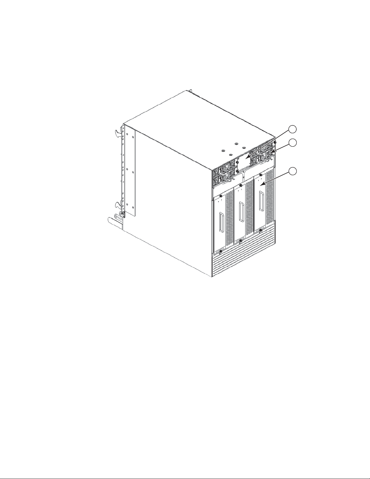
Figure 2 displays a sample configuration of the nonport side view of the Brocade DCX.
1
2
3
1
1 WWN bezel (logo plate) 3 Blower assembly
2Power supply
FIGURE 2 Nonport side of the Brocade DCX (sample configuration)
Brocade DCX Hardware Reference Manual 5
53-1000685-11
Page 20

Brocade DCX blades
1
Brocade DCX blades
Tab le 1 summarizes the port, application, control processor, and core switch blades that are
available for the Brocade DCX.
TABLE 1 Blades available for the Brocade DCX
Description Name Function
Brocade DCX control
processor blade
Brocade DCX core
switch blade
16-port 8-Gbps port
blade
32-port 8-Gbps port
blade
48-port 8-Gbps port
blade
6-port 10-Gbps port
blade
Fibre Channel
application blade
CP8 The CP8 blade contains the control plane for the chassis. There
are two CP8 blades for redundancy. This control processor blade
is compatible with the Brocade DCX and Brocade DCX-4S.
CR8 The CR8 blade contains the ASICs for switching between port
blades. Every port blade connects to every core switch blade.
There are 384 total ports for port blades. Each core switch blade
connects to 128 backplane ports. Core switch blades have
additional front port connectivity to connect multiple chassis and
backplane connections for the storage server blade. This core
switch blade is compatible only with the Brocade DCX.
FC8-16 A 16-port Brocade port blade supporting 1, 2, 4, and 8 Gbps port
speeds. This port blade is compatible with the Brocade 48000
Director, Brocade DCX and Brocade DCX-4S.
FC8-32 A 32-port Brocade port blade supporting 1, 2, 4, and 8 Gbps port
speeds. This port blade is compatible with the Brocade 48000
Director, Brocade DCX and Brocade DCX-4S.
FC8-48 A 48-port Brocade port blade supporting 1, 2, 4, and 8 Gbps port
speeds. This port blade is compatible with the Brocade 48000
Director, Brocade DCX and Brocade DCX-4S.
FC10-6 A 6-port Brocade port blade supporting 10 Gbps port speed.
Blade provides 10-Gbps ISLs. This port blade is compatible with
the Brocade 48000 Director, Brocade DCX and Brocade DCX-4S.
FA4-18 The FR4-18 blade has 16 (1-, 2-, and 4-Gbps) physical ports
supporting Fibre Channel Application Services and 2
10/100/1000 BaseT Ethernet copper interfaces supporting blade
management. This application blade is compatible with the
Brocade 48000 Director, Brocade DCX and Brocade DCX-4S..
6 Brocade DCX Hardware Reference Manual
53-1000685-11
Page 21

Description Name Function
Brocade DCX blades
1
Fibre Channel router
blade
Storage encryption
blade
FCIP extension blade FX8-24 The FX8-24 blade enables FCIP functionality over existing IP
Fibre Channel over
Enthernet blade
FR4-18i The FR4-18i blade has 16 physical Fibre Channel SFP ports
supporting Fibre Channel Routing Services and 2 physical Gigabit
Ethernet (GbE) SFP ports supporting Fibre Channel Over IP (FCIP).
The two physical GbE ports can support up to 16 virtual E_Ports.
This application blade is compatible with the Brocade 48000
Director, Brocade DCX and Brocade DCX-4S.
FS8-18 The FS8-18 blade enables data cryptographic
(encryption/decryption) and data-compression capabilities. It has
16 Fibre Channel optical SFP ports. This application blade is
compatible with the Brocade 48000 Director, Brocade DCX and
Brocade DCX-4S.
infrastructure. It has 12 FC ports, 10 1 GbE ports, and 2 10 GbE
ports available. This application blade is compatible with the
Brocade DCX and Brocade DCX-4S.
FCOE10-24 The FCOE10-24 blade enables FCoE functionality over existing
Ethernet infrastructure utilizing CEE protocols. It has 24 10 GbE
ports available. This application blade is compatible with the
Brocade DCX and Brocade DCX-4S.
Brocade DCX Hardware Reference Manual 7
53-1000685-11
Page 22

High availability
1
High availability
The following features contribute to the Brocade DCX high-availability design:
• Redundant, hot-swappable blades and FRUs.
• Enhanced data integrity on all data paths.
• Fabric Shortest Path First (FSPF) rerouting around failed links.
• Integration with Simple Network Management Protocol (SNMP) managers.
• Automatic control processor failover.
• Nondisruptive “hot” software code loads and activation.
• Easy configuration, save, and restore.
• Hot-swappable World Wide Name (WWN) cards.
The high-availability software architecture of the Brocade DCX provides a common framework for all
applications that reside on the system, allowing global and local states to be maintained through
any component failure. High-availability elements consist of the High Availability Manager, the
heartbeat, the fault/health framework, the replicated database, initialization, and software
upgrade.
The High Availability Manager controls access to the standby control processor, facilitates software
upgrades, prevents extraneous switchover activity, closes and flushes streams, provides flow
control and message buffering, and supports a centralized active and standby state.
Reliability
Serviceability
The Brocade DCX uses the following error detection and correction mechanisms to ensure
reliability of data:
• Error Detection and Correction mechanism, which checks for encoder errors and fault isolation
(EDFI), such as cyclic redundancy checking (CRC), parity checking, checksum, and illegal
address checking.
• Power-on self-test (POST).
• Dual control processors that enable hot, nondisruptive fast firmware upgrades.
• One serial port and two Ethernet ports (on each control processor) for management and for
service. Offline control processor diagnostics and remote diagnostics simplify troubleshooting.
The standby control processor monitors diagnostics to ensure it is operational, should a
failover be necessary.
• Bus monitoring and control of blades and other field-replaceable units (FRUs).
The Brocade DCX provides the following features to enhance and ensure serviceability:
• Modular design with hot-swappable components.
• Flash memory that stores two firmware images per control processor.
• USB port on control processor blades for all tasks that formerly required an FTP/SCP server,
including software and firmware upgrades.
8 Brocade DCX Hardware Reference Manual
53-1000685-11
Page 23

• Nonvolatile random-access memory (NVRAM), containing the OEM serial number, Brocade
serial number, revision information, and part number information.
• Background health-check daemon.
• Memory scrubber, self test, and bus ping to determine if a bus is not functioning.
• RASlog messages.
• SMI-S compliant.
• Watchdog timers.
• Status LEDs.
• Predictive diagnostics analysis through Fabric Watch.
• SNMP (including version 3) integration with higher-layer managers.
Software features
The Fabric OS allows any Fibre Channel-compliant device to attach to the switches as long as it
conforms to the device login, name service, and related Fibre Channel standards. Each operating
environment requires that a Fibre Channel host bus adapter (HBA) be available with a
standards-compliant driver for correct interface to the fabric.
Software features
1
Security
Fabric OS consists of a set of embedded applications running on top of an embedded Linux
operating system kernel. These applications include:
• Name server.
• Alias server.
• Zone server
• Simple Network Management Protocol (SNMP) agent.
• SMI-S compliant API.
• Syslog auditing.
• RCS (Reliable Commit Service).
• NTP.
• Tasks to manage address assignment, routing, link initialization, fabric initialization, link
shutdown, Brocade DCX shutdown, and the user interface.
Tab le 2 highlights some of the key security features available for the Brocade DCX and for other
Brocade enterprise-class products running Fabric OS 5.2.0 or later. For details, contact your
Brocade DCX supplier and refer to the Brocade White Paper, “The Growing Need for Security in
Storage Area Networks”.
Brocade DCX Hardware Reference Manual 9
53-1000685-11
Page 24

Network manageability
1
TABLE 2 Brocade security features
Brocade Security Features
DH-CHAP Login banner
SSHv2 (using AES, 3DES, RSA) Monitoring of attempted security breaches
(through audit logging)
HTTPS (using AES) Monitoring of attempted security breaches
(through Fabric Watch Security Class)
SNPMv3 Fibre Channel security policies: DCC and SCC
FC-SP Trusted Switch (FCS) for central security
management
Secure RPC Management access controls (SNMPv3,
Telnet, FTP, serial port, front panel)
Secure file copy (SCP) Hardware-enforced zoning by WWN,
domain/port ID, or both
Telnet disable Default zoning
Telnet timeout RSCN suppression and aggregation
IP filters (block listeners) Configurable RSCN suppression by port
Secure passwords (centralized control
through RADIUS/CHAP)
Multiple user accounts (MUAs). Up to 255. Event auditing
Role-based access controls (RBACs) Change tracking
Administrative domains/Virtual fabrics Firmware change alerts in Fabric Manager
Boot PROM password reset Persistent port disable
Password hardening policies Persistent domain ID
Upfront login in Web Tools E_Port disable
NTPv3 (to synchronize timestamps)
Network manageability
The Brocade DCX has a single domain and is managed as a single element with the Enterprise
Fabric Connectivity Manager (EFCM)/Fabric Manager (FM). The Brocade DCX responds to its own IP
address and appears as a separate entity to the Telnet protocol and SNMP.
All management interfaces, such as Telnet, Web Tools, standards-compliant SMI-S, and
Management Server, support a “port N within blade M” naming scheme.
The Brocade DCX supports SNMPv1 and SNPMv3. When SNMP devices send SNMP messages to a
management console running SAN management software, the information is stored in a
management information base (MIB). Fabric OS v6.1.1_enc supports the latest Fibre Alliance Fibre
Channel Management (FCMGMT) and Storage Management Initiative (SMI) MIBs, which allow
common information necessary for management software to provide information to a SAN
administrator. Refer to the Fabric OS MIB Reference for additional MIB information.
10 Brocade DCX Hardware Reference Manual
53-1000685-11
Page 25

Chapter
Installation
In this chapter
•Time and items required . . . . . . . . . . . . . . . . . . . . . . . . . . . . . . . . . . . . . . . . . 11
•Site preparation, unpacking the Brocade DCX, and safety. . . . . . . . . . . . . . 12
•Items included with the Brocade DCX . . . . . . . . . . . . . . . . . . . . . . . . . . . . . . 14
•Providing power to the Brocade DCX . . . . . . . . . . . . . . . . . . . . . . . . . . . . . . . 14
•Port numbering . . . . . . . . . . . . . . . . . . . . . . . . . . . . . . . . . . . . . . . . . . . . . . . . 15
•Cable management . . . . . . . . . . . . . . . . . . . . . . . . . . . . . . . . . . . . . . . . . . . . . 16
Time and items required
You can set up and install the Brocade DCX in the following ways:
• As a standalone unit on a flat surface.
• In a 19-in. Electronic Industries Association (EIA) cabinet, using the 14U Rack Mount Kit
(provided).
• In a mid-mount telecommunications (Telco) rack, using the Mid-Mount Rack Kit available from
your Brocade DCX supplier.
This chapter describes how to set up the Brocade DCX as a standalone unit. For rack-mount
installation instructions, refer to the 14U Rack Mount Kit Installation Procedure or the Mid-Mount
Rack Kit Installation Procedure.
2
Tab le 3 describes the main installation and setup tasks and the estimated time required for each,
based on a fully populated Brocade DCX (384 Fibre Channel ports). Configurations with fewer ports
require less time. These time estimates assume a prepared installation site and appropriate power
and network connectivity.
TABLE 3 Installation tasks, time, and items required
Installation task Time estimate Items required
Site preparation and unpacking Brocade
DCX
Brocade DCX Hardware Reference Manual 11
53-1000685-11
30 minutes 1/2-in. socket wrench (to remove pallet bolts).
#2 Phillips screwdriver.
(for cable management comb).
Pallet jack.
Hydraulic lift or assisted lift, able to raise to a
minimum of 55 in. (140 cm), with a minimum
capacity of 113 kg (250 lb). The Brocade DCX
weighs 104 kg (228 lb) with eight FC8-48 port
cards installed (384 ports).
Page 26

Site preparation, unpacking the Brocade DCX, and safety
2
TABLE 3 Installation tasks, time, and items required (Continued)
Installation task Time estimate Items required
Installing rack mount kit 30 minutes Refer to the 14U Rack Mount Kit Installation
Mounting and securing Brocade DCX in
rack
Installing power cables and powering on
the Brocade DCX
Installing SFP and XFP (10-Gbps) optical
transceivers
Attaching fiber optic cables, cable ties, and
cable guides
Establishing serial connection, logging on
to Brocade DCX, and configuring IP
addresses
Installing Ethernet cable(s) and configuring
the Brocade DCX name, policies, domain
ID, PIDs, or additional system parameters
30 minutes
20 minutes Power cables.
30 minutes SFP and XFP (10-Gbps) optical transceivers.
60 minutes Fiber optic cables, cable ties, and pillars.
10 minutes Serial cable (provided in the Brocade DCX
20 minutes Ethernet cabling (optional) for Telnet access.
Procedure or the Mid-Mount Rack Kit
Installation Procedure.
accessory kit).
Workstation computer with a serial port or
terminal server port and a terminal emulator
application (such as HyperTerminal).
Ethernet IP addresses for the Brocade DCX
and for both control processor blades: total
three addresses.
All other configuration parameters optional.
Refer to the Fabric OS Administrator’s Guide
for PID information.
Site preparation, unpacking the Brocade DCX, and safety
NOTE
Read the safety notices before installation (“Safety notices”).
The following steps are required to ensure correct installation and operation.
1. Provide a space that is 14 rack units (14U) high, 61.29 cm (24.09 in.) deep, and 43.74 cm
(17.22 in.). 1U is equal to 4.45 cm (1.75 in.).
2. Plan to install the Brocade DCX with the nonport side facing the air-intake aisle. The Brocade
DCX can be installed facing either direction, if serviceability and cooling requirements are met.
3. Plan for cable management before installing the chassis (“Cable management”).
Cables can be managed in a variety of ways, such as by routing cables below the chassis, to
either side of the chassis, through cable channels on the sides of the cabinet, or by using
patch panels.
4. Ensure that dedicated electrical branch circuits with the following characteristics are available:
• 200 – 240 VAC, 50–60 Hz (two branch circuits)
• 110 - 120 VAC, 50-60 Hz (up to four branch circuits)
• Two cables for 200 - 240 VAC service; up to four cables for 110 - 120 VAC service
• Protected by a circuit breaker in accordance with local electrical codes
12 Brocade DCX Hardware Reference Manual
53-1000685-11
Page 27

Site preparation, unpacking the Brocade DCX, and safety
• Supply circuit, line fusing, and wire size adequate to the electrical rating on the chassis
nameplate
• Location close to the chassis and easily accessible
• Grounded outlets installed by a licensed electrician and compatible with the power cords
ATTENTION
To maximize fault tolerance, connect each power cord to a separate power source.
5. Ensure that the air intake and exhaust vents have a minimum of 2 inches of airspace.
6. Ensure that the air temperature on the air intake side is less than 40 degrees Celsius (104
degrees Fahrenheit) during operation.
CAUTION
Use safe lifting practices when moving the product. (C015)
NOTE
A fully populated Brocade DCX (eight FC8-48 port cards, 384 ports) weighs approximately 104
kg (228 lbs) and requires a hydraulic or assisted lift to install it.
2
7. Unpack and install the Brocade DCX.
a. Cut the bands that encircle the packaging.
b. Remove the lid and the kits and foam from the top of the chassis.
c. Lift the cardboard box off the chassis and remove the plastic bag from around the chassis.
Save the packing materials for use when returning the old chassis.
d. Leave the chassis on top of the plastic shipping tray if the chassis must be transported to
the installation location.
NOTE
The Brocade DCX packaging does not incorporate a wood pallet and pallet brackets. The
chassis sits on top of a plastic shipping tray.
8. Use a pallet jack or other assisted lift to transport the new chassis to the installation area.
Doorways must be wider than 36 in. (91 cm) to accommodate the chassis.
9. Remove the 14U rack mount kit, accessory kit, packing foam, and antistatic plastic from the
chassis and set aside.
10. Remove the chassis door from the Brocade DCX.
11. Remove the cable management comb (Figure 1).
12. Use a lift to raise the chassis to the correct level. If installing the chassis in a cabinet, follow the
instructions provided by the rack kit manufacturer.
13. If applicable, lock the wheels of the lift.
14. Gently slide the chassis onto the final installation surface, ensuring that it remains supported
during the transfer.
15. Ensure that the chassis is oriented so that the nonport side has access to intake air (cool).
Brocade DCX Hardware Reference Manual 13
53-1000685-11
Page 28

Items included with the Brocade DCX
2
16. Reinstall the cable management comb.
17. Reinstall the door.
Items included with the Brocade DCX
The Brocade DCX ships with the following:
• Brocade DCX chassis, populated with:
• Control processor blades (CP8)
• Core switch blades (CR8)
• Port blades and application blades (included based on customer specification)
• Blade slot filler panels (for slots not filled by a port, control processor, or core switch blade)
• WWN cards
• WWN bezel (logo plate)
• Power supplies
• Power supply filler panels (included if there are fewer than four power supplies)
• Blower assemblies
• Cable management comb
• Chassis door
• Accessory kit containing the following items:
• Brocade DCX Backbone QuickStart Guide
• Brocade Documentation CD (contains documents related to the Brocade DCX)
• ESD grounding strap
• RS-232 serial cable. The RS-232 cable has an adapter at one end that can be removed to
provide an RJ-45-style connector.
• 14U rack mount kit with instructions (includes rear brackets and bottom support rails)
Order the optical transceivers (SFP and XFP) from Brocade. The Brocade DCX supports SWL, LWL,
and ELWL transceivers.
NOTE
For information about the SFP and XFP transceivers that are qualified for the Brocade DCX, go to
http://www.brocade.com/products/interop_and_compatibility.jsp.
Providing power to the Brocade DCX
DANGER
Use the supplied power cords. Ensure the facility power receptacle is the correct type, supplies
the required voltage, and is properly grounded. (D004)
14 Brocade DCX Hardware Reference Manual
53-1000685-11
Page 29

Port numbering
1. Connect the AC power cords to the power supply assemblies. One to four power cords are
required depending on electrical service.
2. Connect the power cords to a power source with voltage of 200 to 240 VAC, 47 to 63 Hz
(normally two power cords) or to a power source with voltage of 110 to 120 VAC, 47 to 63 Hz
(two to four power cords).
ATTENTION
Use of the high-voltage line (200 to 240 VAC) is highly recommended because of better
power-conversion efficiency.
3. Turn the AC power switches on the power supplies to ON. The AC power switches light green
when switched on and power is supplied.
4. The Brocade DCX performs a power-on self-test (POST) each time it is powered on. POST takes
approximately 10 minutes and is complete when the indicator light activity displays the
operational state. For information about LED patterns, see Chapter 4, “Monitor System
Components”.
You can bypass POST by using the fastBoot command. You can also disable POST for
successive reboots on the Brocade DCX using the diagDisablePost command.
ATTENTION
To prevent a potential IP address conflict, do not connect the Brocade DCX to the network until
the IP addresses are configured (Chapter 3, “Log In and Configuration”).
2
Port numbering
The Brocade DCX uses the following port numbering method (Appendix D, “Port Numbering
Temp late”).
• FC8-16 port blade—ports are numbered from 0 through 15 from bottom to top.
• FC8-32 port blade—ports are numbered from 0 through 15 from bottom to top on the left set of
• FC8-48 port blade—ports are numbered from 0 through 23 from bottom to top on the left set of
• FC10-6 port blade—ports are numbered from 0 through 5 from bottom to top.
• FA4-18 blade—the 16 physical Fibre Channel ports on this blade are numbered 0 through 15
• FR4-18i blade—the 16 physical Fibre Channel ports on this blade are numbered 0 through 15
• FS8-18 blade—ports are numbered from 0 through 15 from bottom to top.
NOTE
To power off the Brocade DCX, go to “Powering off the Brocade DCX”.
ports and 16 through 31 from bottom to top on the right set of ports.
ports and 24 through 47 from bottom to top on the right set of ports.
from bottom to top. The two 10/100/1000 BaseT ports are numbered from the bottom as A0
and A1.
from bottom to top. The two GbE ports are numbered from the bottom as Ge0 and Ge1. These
ports, when fully configured, enable 16 VE_Ports or VEX _Ports and appear in the switchShow
command as ports 16 through 31.
Brocade DCX Hardware Reference Manual 15
53-1000685-11
Page 30

Cable management
2
• FX8-24 blade—ports are numbered in groups. FC ports from 0 through 11 in two vertical rows
of six ports starting from the bottom left and bottom right in the lower group of 12 ports. They
are labeled FC on the front panel diagram. The two 10 GbE ports are 0 and 1 and are in the
left-hand column just above the FC ports. They are labeled 10GE on the front panel diagram.
The 1 GbE ports are 0 through 9 and are in both columns above the FC and 10GE ports. They
are labeled GE on the front panel diagram. See Figure 42 on page 129. Up to three FC trunking
groups. The three groups are defined as:
• Trunk group 0: FC ports 0,1
• Trunk group 1: FC ports 6,7
• Trunk group 2: FC ports 2,3,4,5,8,9,10,11
• FCOE10-24 blade—ports are numbered from 0 through 23 in two vertical rows from bottom left
to top right. See Figure 43 on page 130.
Slots are numbered 1 through 12, from left to right when facing the port side of the Brocade DCX.
Control processor blades (CP8) can be installed only in slots 6 and 7. Core switch blades (CR8) can
be installed only in slots 5 and 8.
Cable management
The cable management comb (Figure 1) is attached to the chassis under the chassis door and
allows for simple cable management. The comb can be installed without service disruption.
Route the cables down in front of the blades to keep LEDs visible. Leave at least one meter of slack
for each fiber optic cable to provide room to remove and replace blades.
ATTENTION
Do not route the cables in front of the air exhaust vent, which is located at the top of the port side
of the chassis.
If ISL Trunking is in use, group the cables by trunking group. The ports are color-coded to indicate
which ports can be used in the same ISL Trunking group: eight ports marked with solid black ovals
alternate with eight ports marked with oval outlines. See Table 24 for a listing of supported cable
speeds and distances.
Installing ICL cables (optional)
Go to “RRP: Inter-chassis link (ICL) cables” for the procedure to install the ICL cables
16 Brocade DCX Hardware Reference Manual
53-1000685-11
Page 31

Chapter
Log In and Configuration
In this chapter
•Configuring the Brocade DCX . . . . . . . . . . . . . . . . . . . . . . . . . . . . . . . . . . . . . 17
•Establishing a serial connection and logging on to the Brocade DCX . . . . . 18
•Configuring IP addresses . . . . . . . . . . . . . . . . . . . . . . . . . . . . . . . . . . . . . . . . 19
•Establishing an Ethernet connection . . . . . . . . . . . . . . . . . . . . . . . . . . . . . . . 20
•Customizing a switch name . . . . . . . . . . . . . . . . . . . . . . . . . . . . . . . . . . . . . . 21
•Customizing a chassis name . . . . . . . . . . . . . . . . . . . . . . . . . . . . . . . . . . . . . 21
•Setting the domain ID . . . . . . . . . . . . . . . . . . . . . . . . . . . . . . . . . . . . . . . . . . . 21
•Verifying the PID mode and connecting to the fabric . . . . . . . . . . . . . . . . . . 22
•Software licenses . . . . . . . . . . . . . . . . . . . . . . . . . . . . . . . . . . . . . . . . . . . . . . 22
•Backing up the configuration . . . . . . . . . . . . . . . . . . . . . . . . . . . . . . . . . . . . . 23
3
Configuring the Brocade DCX
The Brocade DCX must be configured before it is connected to the fabric, and all of the
configuration commands must be entered through the active CP blade. The Brocade DCX
configuration includes the following parameters:
• IP address and subnet mask for the chassis
• IP addresses, host names, subnet masks, and gateway addresses for both CP blades
• Switch name
• Domain ID for the Brocade DCX (optional)
• WWN for the Brocade DCX
The Brocade DCX WWN is initially set by the factory to match the license ID (which is based on the
chassis serial number). The WWN can be changed but the license ID cannot be modified.
The configuration information is mirrored to the standby CP blade, which allows the current
configuration to remain available even if the active CP blade fails. The configuration information for
the Brocade DCX is stored in the WWN cards and the flash memory of the CP blades. The
configuration can be backed up to a workstation (uploaded) and then downloaded to the active CP
blade if necessary.
The basic steps required for the initial configuration are:
1. Establish a serial connection and log on to the Brocade DCX.
2. Set up IP addresses.
3. Establish an Ethernet connection.
4. Specify a switch name.
Brocade DCX Hardware Reference Manual 17
53-1000685-11
Page 32

Establishing a serial connection and logging on to the Brocade DCX
3
5. Specify a domain ID for the Brocade DCX.
6. Verify the PID mode and connect the Brocade DCX to the fabric.
7. Enable software licenses.
8. Back up the configuration.
Establishing a serial connection and logging on to the Brocade DCX
1. Verify that the Brocade DCX is powered on and that POST is complete by verifying that all power
LED indicators on the port, control processor, and core switch blades display a steady green
light.
2. Remove the shipping cap from the CONSOLE port on the active CP. Use the serial cable
provided with the Brocade DCX to connect the CONSOLE port on the active CP to a computer
workstation. The active CP blade is indicated by an illuminated (blue) LED.
ATTENTION
The CONSOLE port is intended primarily for the initial setting of the IP address and for service
purposes.
3. Access the Brocade DCX using a terminal emulator application (such as HyperTerminal in a
Windows environment or tip in a UNIX environment).
4. Disable any serial communication programs running on the workstation (such as
synchronization programs).
5. Open the terminal emulator application and configure as follows:
For most MS Windows systems:
Bits per second: 9600
Databits: 8
Parity: None
Stop bits: 1
Flow control: None
In a UNIX environment, type the following string at the prompt:
tip /dev/ttyb -9600
If ttyb is already in use, use ttya instead and enter the following string at the prompt:
tip /dev/ttya -9600
When the terminal emulator application stops reporting information, press Enter. You receive
the following login prompt:
CP0 Console Login:
6. Log in to the Brocade DCX as admin. The default password is “password”. At the initial login,
you are prompted to enter new admin and user passwords. Make sure to write down the new
passwords and keep this information in a secure location.
Fabric OS (swDir)
swDir login: admin
Password:
18 Brocade DCX Hardware Reference Manual
53-1000685-11
Page 33

Please change your passwords now.
Use Control-C to exit or press 'Enter' key to proceed.
Password was not changed. Will prompt again at next login
until password is changed.
swDir:admin>
7. (Optional) Modify passwords. Passwords can be 8 to 40 characters long. They must begin with
an alphabetic character. They can include numeric characters, the dot (.), and the underscore
(_). Passwords are case-sensitive, and they are not displayed when you enter them on the
command line.
passwords, refer to the Fabric OS Administrator’s Guide.
To skip modifying the password, press Ctrl-C. For more information on
Configuring IP addresses
The Brocade DCX requires three IP addresses, which are configured using the ipAddrSet command.
IP addresses are required for both CP blades (CP0 and CP1) and for the chassis management IP
(shown as SWITCH under the ipAddrShow command) in the Brocade DCX.
NOTE
The default IP addresses and host names for the Brocade DCX are:
– 10.77.77.75 / CP0 (the CP blade in slot 6 at the time of configuration)
– 10.77.77.74 / CP1 (the CP blade in slot 7 at the time of configuration)
Configuring IP addresses
3
ATTENTION
Resetting an IP address while the Brocade DCX has active IP traffic or has management and
monitoring tools running, such as DCFM, Fabric Watch, and SNMP, can cause traffic to be
interrupted or stopped.
1. Log in to the active CP as admin using the serial cable connection.
2. Set up the Brocade DCX IP address by entering the ipaddrset -chassis command:
swDir:admin> ipAddrSet -chassis
Enter the information at the prompts. Specify the -chassis IP address. The -sw 0 IP address is
no longer valid on this chassis.
NOTE
The addresses 10.0.0.0 through 10.0.0.255 are reserved and used internally by the Brocade
DCX. External IPs must not use these addresses.
3. Set up the CP0 IP address by entering the ipaddrset -cp 0 command:
swDir:admin> ipAddrSet -cp 0
Enter the information at the prompts.
4. Set up the CP1 IP address by entering the ipaddrset -cp 1 command:
swDir:admin> ipAddrSet -cp 1
Enter the information at the prompts.
Brocade DCX Hardware Reference Manual 19
53-1000685-11
Page 34

Establishing an Ethernet connection
3
This is a sample IP configuration:
swDir:admin> ipaddrset -chassis
Ethernet IP Address [0.0.0.0]: 123.123.123.120
Ethernet Subnetmask [0.0.0.0]: 123.123.123.123
Fibre Channel IP Address [0.0.0.0]:
Fibre Channel Subnetmask [0.0.0.0]:
Issuing gratuitous ARP...Done.
Committing configuration...Done.
swDir:admin> ipaddrset -cp 0
Host Name [cp0]:
Ethernet IP Address [10.77.77.75]: 123.123.123.121
Ethernet Subnetmask [0.0.0.0]: 123.123.123.123
Gateway IP Address [0.0.0.0]: 123.123.123.124
IP address is being changed...Done.
Committing configuration...Done.
swDir:admin> ipaddrset -cp 1
Host Name [cp1]:
Ethernet IP Address [10.77.77.74]: 123.123.123.122
Ethernet Subnetmask [0.0.0.0]: 123.123.123.123
Gateway IP Address [0.0.0.0]: 123.123.123.124
IP address of remote CP is being changed...Done.
Committing configuration...Done.
swDir:admin> reboot
5. Type reboot to reboot the Brocade DCX.
6. You can use the serial port to monitor error messages through the serial connection. After
using the port, remove the serial cable and replace the shipping cap on the CONSOLE port.
Establishing an Ethernet connection
NOTE
Connecting the CP blades to a private network/VLAN is recommended.
After using a serial connection to configure the IP addresses for the Brocade DCX (“Configuring IP
addresses”), you can connect the active CP blade to the local area network (LAN).
By establishing an Ethernet connection, you can complete the Brocade DCX configuration using
either a serial session, Telnet, or management applications, such as Web Tools or Fabric Manager.
1. Remove the shipping plug from the Ethernet port on the active CP blade.
2. Insert one end of an Ethernet cable into the Ethernet port.
3. Connect the other end to an Ethernet 10/100/1000 BaseT LAN.
The Brocade DCX can be accessed through a remote connection using any of the management
tools, such as Telnet, Web Tools, or Fabric Manager.
4. To complete any additional Brocade DCX configuration procedures through a Telnet session,
log in to the Brocade DCX by Telnet, using the admin login. The default password is “password”.
20 Brocade DCX Hardware Reference Manual
53-1000685-11
Page 35

Customizing a switch name
The switch name of the Brocade DCX can be up to 15 characters long; can include alpha, numeric,
and underscore characters; and must begin with an alpha character.
NOTE
Changing the name causes a domain address format RSCN to be issued.
1. Type switchName followed by the new name in double quotes.
swDir:admin> switchName "swModularSwitch5"
Committing configuration...
Done.
swModularSwitch5:admin>
2. Record the new name for reference.
Customizing a chassis name
Customizing a switch name
3
For FOS 6.2.0 and later, the chassis name of the Brocade DCX can be up to 15 characters long; can
include alpha, numeric, and underscore characters; and must begin with an alpha character.
1. Type chassisName followed by the new name in double quotes.
switch:admin> chassisname "DCX_chassis_1"
Committing configuration...
Done.
2. Record the new name for reference.
switch:admin> chassisname
DCX_chassis_1
3. Record the new name for reference.
Setting the domain ID
Each switch in the fabric must have a unique domain ID. The domain ID can be manually set
through the configure command or can be automatically set. The default domain ID for the Brocade
DCX is “1”. Use the fabricShow command to view the already assigned domain IDs.
1. Enter switchDisable to disable the Brocade DCX.
2. Enter configure.
3. Enter y at the “Fabric parameters” prompt:
Fabric parameters (yes, y, no, n): [no] y
4. Enter a unique domain ID:
Domain: (1.239) [1] 3
Brocade DCX Hardware Reference Manual 21
53-1000685-11
Page 36

Verifying the PID mode and connecting to the fabric
3
5. Complete the remaining prompts or press Ctrl+D to accept the settings and exit.
6. Enter switchEnable to reenable the Brocade DCX.
Verifying the PID mode and connecting to the fabric
Before connecting the Brocade DCX to the fabric, verify that the port identifier (PID) mode on the
Brocade DCX matches the other switches in the fabric. This parameter must be identical for all
switches in the fabric and is set using the configure command.
1. Add SFP optical transceivers (or XFP optical transceivers with FC10-6 port card installed) and
cables to the Fibre Channel ports.
The ports are color-coded to indicate which can be used in the same port group for trunking
(trunking port groups can be up to 8 ports). The ports and cables used in trunking groups must
meet specific requirements. Refer to the Fabric OS Administrator’s Guide.
2. Position one of the optical transceivers so that the key is oriented correctly to the port. Insert
the transceiver into the port until it is firmly seated and the latching mechanism clicks.
Transceivers are keyed so that they can only be inserted with the correct orientation. If a
transceiver does not slide in easily, ensure that it is correctly oriented.
3. Position a cable so that the key (the ridge on one side of the cable connector) is aligned with
the slot in the transceiver. Insert the cable into the transceiver until the latching mechanism
clicks.
Cables are keyed so that they can be inserted in only one way. If a cable does not slide in
easily, ensure that it is correctly oriented.
4. Repeat step 1 through step 3 for the remaining ports.
5. Organize the cables (“Cable management”).
6. Verify the Brocade DCX and port status using the switchShow command.
7. Verify fabric connectivity using the fabricShow command.
Software licenses
Depending on the vendor agreement, certain licenses are factory installed on the Brocade DCX. To
determine which licenses are enabled, use the licenseShow command.
swDir:admin> licenseshow
AAbbccDDeeFFeeGG:
Web license
Zoning license
Extended Fabric license
Fabric Watch license
Performance Monitor license
Trunking license
Security license
In this example, the license key is AAbbccDDeeFFeeGG. Keep a copy of the license key for
reference.
22 Brocade DCX Hardware Reference Manual
53-1000685-11
Page 37

The 64-bit chassis ID is required to obtain and activate licenses for the Brocade DCX. The chassis
ID is available through the licenseIdShow command. The licenseShow and licenseIdShow
commands must be entered on the active CP blade. Refer to the Fabric OS Administrator’s Guide.
Backing up the configuration
To backup the configuration:
1. Enter the configupload command. This command uploads the Brocade DCX configuration to
the server so that it is available for downloading to a replacement Brocade DCX.
2. You can run the following commands to save the configuration to a file on a secure host.
• configShow
• ipaddrShow
• licenseShow
• switchShow
3. Alternatively, you can save the configuration file to a Brocade USB.
Backing up the configuration
3
NOTE
Passwords are not saved in the configuration file, and are not uploaded during a configUpload.
Brocade DCX Hardware Reference Manual 23
53-1000685-11
Page 38

Backing up the configuration
3
24 Brocade DCX Hardware Reference Manual
53-1000685-11
Page 39

Chapter
Monitor System Components
In this chapter
•Monitoring overview . . . . . . . . . . . . . . . . . . . . . . . . . . . . . . . . . . . . . . . . . . . . 25
•Determining the status of a port or application blade . . . . . . . . . . . . . . . . . 25
•Determining the status of a control processor blade (CP8) . . . . . . . . . . . . . 38
•Determining status of a core switch blade (CR8) . . . . . . . . . . . . . . . . . . . . . 40
•Determining the status of a power supply. . . . . . . . . . . . . . . . . . . . . . . . . . . 41
•Determining the status of a blower assembly. . . . . . . . . . . . . . . . . . . . . . . . 42
•Determining the status of a WWN card . . . . . . . . . . . . . . . . . . . . . . . . . . . . . 44
Monitoring overview
The Brocade DCX is engineered for reliability and requires no routine operational steps or
maintenance. This chapter provides information about determining the status of each component
using LEDs and CLI commands. Refer to the Web Tools Administrator’s Guide and the Fabric OS
Administrator’s Guide for additional information.
4
Determining the status of a port or application blade
1. Check the LEDs on the blade.
• Figure 3 illustrates the FC8-16 port blades.
• Figure 4 illustrates the FC8-32 port blades.
• Figure 5 illustrates the FC8-48 port blade.
• Figure 6 illustrates the FC10-6 port blade.
• Figure 7 illustrates the FR4-18i application blade
• Figure 8 illustrates the FA4-18 application blade.
• Figure 9 illustrates the FS8-18 application blade.
• Figure 10 illustrates the FX8-24 extension blade.
• Figure 11 illustrates the FCOE10-24 FCOE blade.
The LED patterns may temporarily change during POST and other diagnostic tests. For
information about how to interpret the LED patterns, see Table 4.
2. Check the blade status by entering slotShow.
Brocade DCX Hardware Reference Manual 25
53-1000685-11
Page 40

Determining the status of a port or application blade
4
1
2
3
4
1 Power LED 3 Fibre Channel port
2 Status LED 4 Port Status LED
FIGURE 3 FC8-16 Port blade
26 Brocade DCX Hardware Reference Manual
53-1000685-11
Page 41

Determining the status of a port or application blade
4
1
2
3
4
1 Power LED 3 Fibre Channel port
2 Status LED 4 Port Status LED
FIGURE 4 FC8-32 Port blade
Brocade DCX Hardware Reference Manual 27
53-1000685-11
Page 42

Determining the status of a port or application blade
4
!
!
47
23
46
22
45
21
44
20
43
19
42
18
41
17
40
16
39
15
38
14
37
13
36
12
35
11
34
10
33
9
32
8
31
7
30
6
29
5
28
4
27
3
26
2
25
1
24
0
1
47
2
35
11
3
34
10
4
33
9
32
8
1 Power LED 3 Fibre Channel port
2 Status LED 4 Port Status LED
FIGURE 5 FC8-48 Port blade
28 Brocade DCX Hardware Reference Manual
53-1000685-11
Page 43

Determining the status of a port or application blade
4
1
2
3
4
1 Power LED 3 Fibre Channel port
2 Status LED 4 Port Status LED
FIGURE 6 FC10-6 Port blade
Brocade DCX Hardware Reference Manual 29
53-1000685-11
Page 44

Determining the status of a port or application blade
4
!
!
15
14
13
12
11
10
9
8
7
6
5
4
1
7
6
5
2
3
4
4
3
2
1
0
GE0
GE1
FR4
18i
1 Power LED 3 Fibre Channel port
2 Status LED 4 Port Status LED
FIGURE 7 FR4-18i Application blade
30 Brocade DCX Hardware Reference Manual
53-1000685-11
Page 45

Determining the status of a port or application blade
!
!
15
14
13
12
11
10
9
8
7
6
5
4
3
2
1
0
1
2
7
3
6
4
5
4
4
A0
A1
FA4
18
1 Power LED 3 Fibre Channel port
2 Status LED 4 Port Status LED
FIGURE 8 FA4-18 Application blade
Brocade DCX Hardware Reference Manual 31
53-1000685-11
Page 46

Determining the status of a port or application blade
4
1 Power LED 3 Fibre Channel port
2 Status LED 4 Port Status LED
FIGURE 9 FS8-18 Application blade
32 Brocade DCX Hardware Reference Manual
53-1000685-11
Page 47

Determining the status of a port or application blade
76
2
3
1
4
5
1 10 GbE ports 0-1 5 FC ports 0-5
21 GbE ports 0-3 6Power LED
31 GbE ports 4-9 7Status LED
4FC ports 6-11
4
FIGURE 10 FX8-24 Extension blade
See “FX8-24 blade” for information about trunking groups on this blade.
Brocade DCX Hardware Reference Manual 33
53-1000685-11
Page 48

Determining the status of a port or application blade
2
1
43
4
1 10 GbE FCoE ports 12-23 3 Power LED
2 10 GbE FCoE ports 0-11 4 Status LED
FIGURE 11 FCOE10-24 FCoE blade
34 Brocade DCX Hardware Reference Manual
53-1000685-11
Page 49

Determining the status of a port or application blade
4
Tab le 4 describes the port and application blade LED patterns and the recommended actions for
those patterns.
TABLE 4 Port and application blade LED descriptions
LED purpose Color Status Recommended action
Power LED Steady green Blade is enabled. No action required.
No light (LED is off) Blade is not powered on. Ensure that the blade is firmly
seated and either the
thumbscrew is fully engaged or
the slider is pushed up and the
ejectors are fully engaged..
Status LED No light (LED is off) Blade is either healthy or does
not have power.
Steady amber Blade is faulty. Ensure that the blade is firmly
Slow-flashing amber (on 2
seconds, then off 2
seconds)
Fast-flashing amber (on
1/2 second, then off 1/2
second)
Blade is not seated correctly or
is faulty.
Environmental range exceeded. Check for out-of-bounds
Verify that the power LED is on.
seated and check the status by
entering the slotShow
command. If LED remains
amber, consult the Brocade
DCX supplier.
Pull the blade out and reseat it.
If LED continues to flash,
replace the blade.
environmental condition and
correct it.
Brocade DCX Hardware Reference Manual 35
53-1000685-11
Page 50

Determining the status of a port or application blade
4
TABLE 4 Port and application blade LED descriptions (Continued)
LED purpose Color Status Recommended action
FC Port Status No light (LED is off) Port has no incoming power, or
there is no light or signal carrier
detected.
Polling is in progress. Allow 60 seconds for polling to
Connected device is configured
in an offline state.
Steady green Port is online (connected to an
external device) but has no
traffic.
GbE Port Status
(FX8-24) - both
1 GbE and 10
GbE ports
Slow-flashing green (on 1
second, then off 1 second)
Fast-flashing green (on
1/4 second, then off
1/4 second
Flickering green Port is online, with traffic
Steady amber Port is receiving light or signal
Slow-flashing amber (on 2
seconds, then off 2
seconds)
Fast-flashing amber
(on 1/2 second, then
off 1/2 second)
Alternating green/amber Port is bypassed. Reset the port from the
No light (LED is off) Port has no incoming power, or
Steady green Port is online but has no traffic. No action required.
Slow-flashing green (on 1
second, then off 1 second)
Flickering green Port is online, with traffic
Fast-flashing amber
(on 1/4 second, then
off 1/4 second)
Port is online but segmented,
indicating a loopback plug or
cable or an incompatible switch.
Port is in internal loopback
(diagnostic).
flowing through port.
carrier, but it is not online yet.
Port is disabled due to
diagnostic tests or portDisable
or portCfgPersistentEnable
command.
Transceiver or port is faulty. Change the transceiver or reset
there is no light or signal carrier
detected.
Beacon. Used to identify
specific ports.
flowing through port.
Transceiver or port is faulty. Change the transceiver or reset
Verify that the power LED is on,
check the transceiver and
cable.
complete.
Verify the status of the
connected device.
No action required.
Verify that the correct device is
attached to the Brocade DCX.
No action required.
No action required.
Reset the port from the
workstation using the
portEnable or
portCfgPersistentEnable
command.
Reset the port from the
workstation using the
portEnable or
portCfgPersistentEnable
command.
the switch from the workstation.
workstation using the
portEnable or
portCfgPersistentEnable
command.
Verify that the power LED is on,
check the transceiver and
cable.
No action required.
No action required.
the switch from the workstation.
36 Brocade DCX Hardware Reference Manual
53-1000685-11
Page 51

Determining the status of a port or application blade
TABLE 4 Port and application blade LED descriptions (Continued)
LED purpose Color Status Recommended action
4
10GbE Port
Status
(FCOE10-24)
No light (LED is off) Port is offline. Verify that the power LED is on,
check the transceiver and
cable.
Steady green Port is online but has no traffic. No action required.
Flickering green Port is online, with traffic
flowing through port.
Steady amber Port is receiving light but it is
not online yet.
Slow-flashing amber (on 2
seconds, then off 2
seconds)
Fast-flashing amber
(on 1/4 second, then
off 1/4 second)
Port is disabled. Enable the port by using the “no
Transceiver or port is faulty. Change the transceiver or reset
No action required.
Reset the port by doing a
“shutdown” and “no shutdown”
sequence from a cmsh session.
shutdown” command from a
cmsh session.
the port by doing a “shutdown”
and “no shutdown” sequence
from a cmsh session.
For more information on the CEE Management Shell (cmsh), see the Fabric OS Command
Reference Manual or the Converged Enhanced Ethernet Command Reference.
Brocade DCX Hardware Reference Manual 37
53-1000685-11
Page 52

Determining the status of a control processor blade (CP8)
4
Determining the status of a control processor blade (CP8)
1. Check the LED indicators on the CP blade (Figure 12). The LED patterns may temporarily
change during POST and other diagnostic tests. For information about how to interpret the LED
patterns, see Table 5.
2. Check the port blade status by entering slotShow and haShow.
Figure 12 identifies the CP8 blade.
1
3
4
5
6
7
8
2
1 Status LED 5 Console port (10101)
2 Power LED 6 Ethernet port (MGM IP)
3 USB LED 7 Ethernet port (SERVICE IP)
4USB port 8Active CP LED
FIGURE 12 Control processor blade (CP8)
38 Brocade DCX Hardware Reference Manual
53-1000685-11
Page 53

Determining the status of a control processor blade (CP8)
Tab le 5 describes the CP blade LED patterns and the recommended actions for those patterns.
TABLE 5 CP blade LED descriptions
LED purpose Color Status Recommended action
Power Steady green CP blade is on. No action required.
No light (LED is off) CP blade is not on. Ensure that the blade is firmly
seated and has power.
4
Status No light (LED is off) CP blade is either healthy
or does not have power.
Steady amber CP blade is faulty or the
switch is still booting.
Slow-flashing amber (on 2
seconds; then off 2 seconds)
Fast-flashing amber (on 1/2
second; then off 1/2 second)
Ethernet Link
Status
Ethernet Link
Speed
USB Status Lamp on USB stick enabled. No action required.
Active CP Steady blue Active CP blade. No action required.
No light (LED is off) Either an Ethernet link is
Flickering green/amber Ethernet link is healthy
No light (LED is off) Ethernet link speed is 10
Steady green Ethernet link speed is
Lamp off USB stick not present or
No light (LED is off) Standby CP blade. No action required.
CP blade is not seated
correctly or is faulty.
Environmental range
exceeded.
not detected, or it does not
have incoming power.
and traffic is flowing
through port.
Mb/s or CP blade does not
have incoming power.
100/1000 Mb/s.
disabled.
Verify that the power LED is on.
Ensure that the blade is firmly
seated and the switch has
completed booting. If LED remains
yellow, consult the Brocade DCX
supplier.
Pull the blade out and reseat it. If
the LED continues to flash, replace
the blade.
Check for out-of-bounds
environmental condition and
correct it.
Ensure that the blade has power,
the Ethernet cable is firmly seated,
and the connected device is
functioning.
No action required.
Ensure that the CP has power.
NOTE: To force a persistent Ethernet
link speed, enter the ifModeSet
command.
No action required.
No action required.
Brocade DCX Hardware Reference Manual 39
53-1000685-11
Page 54

Determining status of a core switch blade (CR8)
4
Determining status of a core switch blade (CR8)
1. Check the LED indicators on the core switch blade (Figure 12). The LED patterns may
temporarily change during POST and other diagnostic tests; for information about how to
interpret the LED patterns, see Table 5.
2. Check the core switch blade status by entering slotShow and haShow.
Figure 13 identifies the core switch blade.
LINK ATTN
ICL 1
LINK ATTN
ICL 0
1
LINK ATTN
ICL 0
2
3
4
5
1 Status LED 4 ATTN LED
2 Power LED 5 ICL connector
3LINK LED
FIGURE 13 Core switch blade (CR8)
40 Brocade DCX Hardware Reference Manual
53-1000685-11
Page 55

Determining the status of a power supply
Tab le 6 describes the core switch blade LED patterns and the recommended actions for those
patterns.
TABLE 6 CR blade LED descriptions
LED purpose Color Status Recommended action
Power Steady green CP blade is on. No action required.
No light (LED is off) CP blade is not on. Ensure that the blade is firmly
seated and has power.
4
Status No light (LED is off) CP blade is either healthy
or does not have power.
Steady amber CP blade is faulty or the
switch is still booting.
Slow-flashing amber (on 2
seconds; then off 2 seconds)
Fast-flashing amber (on 1/2
second; then off 1/2 second)
LINK LED No light (LED is off) No ICL or ICL cable
Steady green ICL connected. No action required.
ATTN LED No light (LED is off) ICL operational. No action required.
Blinking amber Attention required. Ensure that the ICL cable is
CP blade is not seated
correctly or is faulty.
Environmental range
exceeded.
present, but no
connection.
Determining the status of a power supply
Verify that the power LED is on.
Ensure that the blade is firmly
seated and the switch has
completed booting. If the LED
remains yellow, consult the Brocade
DCX supplier.
Pull the blade out and reseat it. If
the LED continues to flash, replace
the blade.
Check for out-of-bounds
environmental condition and
correct it.
Ensure that the ICL cable is
correctly installed.
correctly installed.
1. Check the LED indicator on the power supply (Figure 14). The LED patterns may temporarily
change during POST and other diagnostic tests; for information about how to interpret the LED
patterns, see Table 7 .
2. Check the power supply status by entering psShow.
The power supply status displays OK, Absent, or Faulty. If a power supply is absent or faulty,
contact the Brocade DCX supplier to order replacement parts.
Figure 14 displays the power supply.
Brocade DCX Hardware Reference Manual 41
53-1000685-11
Page 56

Determining the status of a blower assembly
4
1Power LED
FIGURE 14 Power supply
Tab le 7 describes the power supply LED patterns and the recommended actions for those patterns.
TABLE 7 Power supply LED descriptions
LED purpose Color Status Recommended action
1
Power No light
(LED is off)
Steady green Power supply has incoming
Flashing green Power supply is about to fail. Replace the power supply.
Power supply does not have
incoming power and is not
providing power to the Brocade
DCX.
power and is providing power to
the Brocade DCX.
Determining the status of a blower assembly
1. Check the LED indicators on the blower assembly (Figure 15). The LED patterns may
temporarily change during POST and other diagnostic tests; for information about how to
interpret the LED patterns, see Table 8 .
2. Check the blower assembly status using the fanShow command.
The status for each blower assembly displays OK, Absent, or Faulty. The RPM of each fan in the
assembly is also provided. If a blower assembly is absent or faulty, contact the Brocade DCX
supplier to order replacement parts.
Figure 15 displays the blower assembly.
Ensure that the power supply is
firmly seated, the Brocade DCX has
incoming power, both power cables
are connected, and AC power
switches are on.
No action required.
42 Brocade DCX Hardware Reference Manual
53-1000685-11
Page 57

Determining the status of a blower assembly
12
4
1Power LED 2Fault LED
FIGURE 15 Blower assembly
TABLE 8 Blower assembly LED descriptions
LED purpose Color Status Recommended action
Power No light
(LED is off)
Steady green Blower assembly has
Fault No light
(LED is off)
Steady amber Blower assembly has a
Slow-flashing amber
(on 2 sec, then off 2 sec)
Flashing amber
(on 1/2 sec, then off 3.5 sec)
Fast-flashing amber
(on 1/2 sec, then off 1/2 sec)
Blower assembly does not
have power.
power.
Blower assembly is either
healthy or does not have
power.
failure (full or partial).
Blower assembly is not
seated correctly or is
faulty.
Fan is disabled. Run the fanEnable command to
Environmental range
exceeded.
Ensure that the blower assembly
is firmly seated and has power.
No action required.
Ensure that the blower assembly
has power.
Replace the blower assembly.
Pull the unit out and reseat it. If
the LED continues to flash,
replace the unit.
enable the fan.
Check for out-of-bounds
environmental condition, resolve
any problems, and reseat the
unit. If the LED continues to flash,
replace the unit.
Brocade DCX Hardware Reference Manual 43
53-1000685-11
Page 58

Determining the status of a WWN card
4
Determining the status of a WWN card
NOTE
The WWN bezel (logo plate) covers the WWN cards. The LEDs on the WWN cards are not visible
unless the bezel is removed.
1. Enter the chassisShow command to display information about the WWN card. (WWN units
correspond to information specific to the WWN card.) Error messages that may indicate
problems with a WWN card are summarized in Table 9.
TABLE 9 Messages that may indicate WWN card failure
Type of message Sample error message
WWN unit fails its FRU (field
replaceable unit) header access.
WWN unit is being faulted. 0x24c (fabos): Switch: switchname, Critical
WWN unit is not present or is not
accessible.
Writing to the FRU history log
(hilSetFruHistory) has failed.
0x24c (fabos): Switch: switchname, error
EM-I2C_TIMEOUT, 2, WWN 1 I2C timed out: state 0x4
EM-WWN_UNKNOWN, 1, Unknown WWN #2 is being
faulted
0x24c (fabos): Switch: switchname, Error
EM-WWN_ABSENT, 2, WWN #1 not present
0x24c (fabos): Switch: switchname, Error
EM-HIL_FAIL, 2, HIL Error: hilSetFruHistory
failed, rc=-3 for SLOT 3
Figure 16 displays the WWN bezel (logo plate).
1
2
3
4
1 CP blade Status (above) and Power (below) LEDs 3 Port blade Status (above) and Power (below) LEDs
2 CR blade Status (above) and Power (below) LEDs 4 Slot numbers
FIGURE 16 WWN bezel (logo plate)
Tab le 10 describes the WWN card LED patterns and the recommended actions for those patterns.
44 Brocade DCX Hardware Reference Manual
53-1000685-11
Page 59

Determining the status of a WWN card
TABLE 10 WWN bezel LED descriptions
LED purpose Color Status Recommended action
4
Port blade/CP blade/
CR blade
Power
Port blade/CP blade/
CR blade
Status
NOTE: If a blade slot or power supply bay has a filler panel installed, the corresponding LEDs on the WWN blade do
not light up.
Steady green Power is OK. No action required.
Steady amber Blade is faulty. Check the blade.
No light (LED is OFF) Blade is OK. No action required.
Brocade DCX Hardware Reference Manual 45
53-1000685-11
Page 60

Determining the status of a WWN card
4
46 Brocade DCX Hardware Reference Manual
53-1000685-11
Page 61

Chapter
Removal and Replacement Procedures (RRPs)
In this chapter
•RRP: Chassis door . . . . . . . . . . . . . . . . . . . . . . . . . . . . . . . . . . . . . . . . . . . . . . 47
•RRP: Cable management comb . . . . . . . . . . . . . . . . . . . . . . . . . . . . . . . . . . . 49
•RRP: Port, application, and encryption blade . . . . . . . . . . . . . . . . . . . . . . . . 50
•RRP: Blade filler panel . . . . . . . . . . . . . . . . . . . . . . . . . . . . . . . . . . . . . . . . . . 54
•RRP: Control processor blade (CP8). . . . . . . . . . . . . . . . . . . . . . . . . . . . . . . . 55
•RRP: Core switch blade (CR8). . . . . . . . . . . . . . . . . . . . . . . . . . . . . . . . . . . . . 61
•RRP: Power supply. . . . . . . . . . . . . . . . . . . . . . . . . . . . . . . . . . . . . . . . . . . . . . 64
•RRP: Blower assembly. . . . . . . . . . . . . . . . . . . . . . . . . . . . . . . . . . . . . . . . . . . 67
•RRP: WWN bezel (logo plate) and WWN card . . . . . . . . . . . . . . . . . . . . . . . . 69
•RRP: SFPs and XFPs . . . . . . . . . . . . . . . . . . . . . . . . . . . . . . . . . . . . . . . . . . . . 73
•RRP: Inter-chassis link (ICL) cables . . . . . . . . . . . . . . . . . . . . . . . . . . . . . . . . 74
•RRP: Brocade DCX chassis . . . . . . . . . . . . . . . . . . . . . . . . . . . . . . . . . . . . . . . 82
5
Introduction
NOTE
Read the safety notices before servicing (“Safety notices”).
The field replaceable units (FRUs) in the Brocade DCX can be removed and replaced without
special tools. The Brocade DCX can continue operating during many of the FRU replacements if the
conditions specified in the procedure are followed.
The following sections contain FRU removal and replacement procedures (RRPs).
RRP: Chassis door
NOTE
The chassis door must be installed to ensure the Brocade DCX meets EMI and other regulatory
certifications.
Time and items required
The replacement procedure for the chassis door takes less than 5 minutes.
Brocade DCX Hardware Reference Manual 47
53-1000685-11
Page 62

RRP: Chassis door
5
Removing a chassis door
• Support the door to prevent it from falling. Pull and remove the door.
FIGURE 17 RRP: Chassis door
Replacing a chassis door
1. Align the holes in the door with the pins in the chassis
2. Push the door into place.
48 Brocade DCX Hardware Reference Manual
53-1000685-11
Page 63

RRP: Cable management comb
The Brocade DCX can continue to operate during the replacement of the cable management comb.
Time and items required
The replacement procedure for the cable management comb takes less than 5 minutes. A #1
Phillips screwdriver is required.
Removing a cable management comb
1. Rearrange the cables around the cable management comb.
2. Unscrew and save the four screws holding the comb to the chassis (Figure 18). Support the
comb to prevent it from falling
3. Remove the cable management comb.
RRP: Cable management comb
5
FIGURE 18 RRP: Cable management comb
Replacing a cable management comb
1. Position and tighten the four screws to secure the cable management comb to the chassis.
2. Arrange the cables along the cable management comb.
Brocade DCX Hardware Reference Manual 49
53-1000685-11
Page 64

RRP: Port, application, and encryption blade
5
RRP: Port, application, and encryption blade
This section describes how to remove and replace port, application, and encryption blades.
ATTENTION
A filler panel should be removed only when being replaced with a port, application, or encryption
blade, or a filler panel (“RRP: Blade filler panel”). Any slot that is not occupied by a blade should be
occupied by a filler panel to ensure correct cooling of the chassis and protection from dust.
Slots are numbered from 1 through 12, from left to right when facing the port side of the Brocade
DCX. Port, application, and encryption blades can be installed in slots 1 through 4 and 9 through
12.
Time and items required
The replacement procedure for each blade takes less than 10 minutes. The following items are
required for the blade and filler panel replacement:
• ESD (electrostatic discharge) grounding strap
• Workstation computer
• Replacement blade or filler panel
• Phillips screwdriver
• Small form-factor pluggable (SFP) or extended form-factor pluggable (XFP, FC10-6 blade only)
transceivers (as needed)
• Optical cables (as needed)
Removing a blade
ATTENTION
Follow ESD precautions (“ESD precautions”).
NOTE
The FC8-16, FC8-32, FC-48, FC10-6, FR4-18i, and FA4-18 blades are compatible with the Brocade
DCX, Brocade DCX-4S, and the Brocade 48000. The FS8-18 encryption blade and the FX8-24 and
FCOE10-24 blades are compatible only with the Brocade DCX and DCX-4S.
1. Remove the chassis door (“RRP: Chassis door”).
2. Check the power LED, status LED, and port status LED to identify any possible problems. A
failed blade can be identified by inspecting the LEDs on the front panel of each blade. See
Figure 3 to Figure 9 for LED locations.
3. Establish a Telnet or console session.
Before replacing a blade, establish a Telnet or console connection to determine a failure and
verify operation after replacement. Use the switchShow command to view the status of blades.
4. Check for adequate cable slack. Ensure there is plenty of cable slack to remove a blade
without cable obstruction.
50 Brocade DCX Hardware Reference Manual
53-1000685-11
Page 65

RRP: Port, application, and encryption blade
5. Ensure that the part number on the unit being replaced matches the replacement part
number. The chassisShow command displays information about the blades, including part
numbers (xx-000xxxx-xx), serial numbers, and additional status.
6. Ensure that traffic is not flowing through the blade (port status LED should be off) prior to
disconnecting cables.
NOTE
Before removing any cables from a blade, note the cable order (identify each cable by its
physical port). If multiple blades are being replaced, replace one blade at a time.
7. Ensure that traffic is not flowing through the blade.
8. Disconnect all cables and SFP or XFP transceivers from the blade.
9. Perform the appropriate following action based on the type of blade:
• For FC8-16, FC8-32, FC8-48 port blades, FX8-24, FCOE10-24 application blades, and
FS8-18 encryption blade: Unscrew the two thumb screws from the top and bottom ejectors
on the blade using the Phillips screwdriver. Unscrew the top thumb screw until it pops out.
This initiates a hot-swap request. Adjust the ejectors to the open position (Figure 19).
• For FC10-6 port blade, and FA4-18, and FR4-18i application blades: Turn the blade off by
sliding the slider switch in the top ejector down, to the off position. This initiates a
hot-swap request.
5
10. Wait for the power LED to turn off in response to the hot-swap request before removing the
blade.
11. Perform the appropriate following action based on the type of blade:
• For FC8-16, FC8-32, and FC8-48 port blades, FX8-24, FCOE10-24 application blades, and
FS8-18 encryption blade: Open the ejectors. Pull the blade out of the chassis using the
ejectors (Figure 19).
• For FC10-6 port blade, and FA4-18, and FR4-18i application blades: Unscrew the two
thumb screws from the top and bottom ejectors on the blade using the Phillips
screwdriver. Lever both ejectors open simultaneously to approximately 45 degrees and
pull the blade out of the chassis.
12. If the blade is not being replaced by another blade, install a filler panel (“RRP: Blade filler
panel”).
Brocade DCX Hardware Reference Manual 51
53-1000685-11
Page 66

RRP: Port, application, and encryption blade
5
FIGURE 19 RRP: Port, application, and encryption blade (FC8-48 port blade shown)
Replacing a blade
ATTENTION
Follow ESD precautions (“ESD precautions”).
NOTE
A FA4-18i application blade and the Brocade DCX must have the same version of firmware. To
upgrade firmware versions, refer to the Fabric OS Administrator’s Guide.
52 Brocade DCX Hardware Reference Manual
53-1000685-11
Page 67

RRP: Port, application, and encryption blade
1. Orient the blade so that the ports are at the front of the chassis and the flat side of the blade is
on the left.
2. Perform the appropriate following action based on the type of blade:
5
• For FC8-16, FC8-32, FC8-48 port blades, FX8-24, FCOE10-24 application blades, and
FS8-18 encryption blade: Adjust the ejectors to the open position, align the flat side of the
blade inside the upper and lower rail guides in the slot, and slide the blade into the slot
until it is firmly seated.
• For FC10-6 port blade, and FA4-18, and FR4-18i application blades: Open the ejectors to
approximately 45 degrees, align the flat side of the port blade inside the upper and lower
rail guides in the slot, and slide the blade into the slot, with slight pressure to the left, until
it is firmly seated.
3. Perform the appropriate following action based on the type of blade:
• For FC8-16, FC8-32, FC8-48 port blades, FX8-24, FCOE10-24 application blades, and
FS8-18 encryption blade: Adjust the ejectors to the closed position by pulling them away
from the center of the blade.
• For FC10-6 port blade, and FA4-18, and FR4-18i application blades: Close the ejectors by
pushing the handles toward the center of the blade until the ejectors lock. The levering
action of the handles seats the blade in the slot.
4. Perform the appropriate following action based on the type of blade:
• For FC8-16, FC8-32, FC8-48 port blades, FX8-24, FCOE10-24 application blades, and
FS8-18 encryption blade: Tighten the upper and lower thumb screws using the Phillips
screwdriver.
• For FC10-6 port blade, and FA4-18, and FR4-18i application blades: Tighten the thumb
screw inside each handle using the Phillips screwdriver.
5. Perform the appropriate following action based on the type of blade:
• For FC8-16, FC8-32, FC8-48 port blades, FX8-24, FCOE10-24 application blades, and
FS8-18 encryption blade: Skip to step 6.
• For FC10-6 port blade, and FA4-18, and FR4-18i application blades: Turn the blade on by
sliding the slider switch in the top ejector up, covering the thumb screw.
6. Verify that the power LED on the port blade is displaying a steady green light. If it does not turn
on, ensure that the blade is firmly seated.
7. Install the SFP or XFP (FC10-6 only) transceivers and cables in the port blade.
8. Group and route the cables.
9. Replace the chassis door (“RRP: Chassis door”).
Brocade DCX Hardware Reference Manual 53
53-1000685-11
Page 68

RRP: Blade filler panel
5
RRP: Blade filler panel
This section describes how to remove and replace blade filler panels.
Removing a filler panel
ATTENTION
A filler panel should be removed only when being replaced with a port, application, or encryption
bl ade, or new filler panel. Any slot t hat is not occupied by a blade should be occupied by a filler panel
to ensure correct cooling of the chassis and protection from dust.
1. Remove the chassis door (“RRP: Chassis door”).
2. Unscrew the thumb screw at the bottom of the panel using the Phillips screwdriver.
3. Pull the filler panel out of the chassis (Figure 20).
FIGURE 20 RRP: Port and application blade filler panel
54 Brocade DCX Hardware Reference Manual
53-1000685-11
Page 69

Replacing a filler panel
1. Orient the filler panel (Figure 20).
2. Slide the filler panel into the slot until it is firmly seated.
3. Tighten the thumb screw at the bottom of the panel.
4. Replace the chassis door (“RRP: Chassis door”).
RRP: Control processor blade (CP8)
This section describes how to remove and replace a control processor (CP8) blade. Each Brocade
DCX has two CP8 blades located in slot 6 and slot 7.
NOTE
If the new CP blade does not have the same firmware as the active CP blade, the new blade must
be upgraded to the same firmware version. Refer to the Fabric OS Administrator’s Guide for
information.
RRP: Control processor blade (CP8)
5
Time and items required
The replacement procedure for the CP blade takes approximately 30 minutes. The following items
are required for the CP blade replacement:
• ESD (electrostatic discharge) grounding strap
• Workstation computer
• Serial cable
• IP address of an FTP server for backing up the Brocade DCX configuration
• Phillips #2 screwdriver
• Replacement CP blade. Requires the Brocade DCX CP blade (CP8)
Verifying the necessity of replacement
Confirm that you need to replace the CP blade. The following events might indicate that a CP blade
is faulty:
• The status LED on the CP blade is lit amber, or the power LED is not lit.
• The CP blade does not respond to Fabric OS commands, or the serial console is not available.
• The slotShow command does not show that the CP blade is enabled.
• The haShow command indicates an error.
• The clock is inaccurate, or the CP blade does not boot up or shut down normally.
• Any of the following messages display in the error log:
• “Slot unknown” message relating to a CP slot
• CP blade errors or I
• FRU: FRU_FAULTY messages for a CP blade
• Configuration loader messages or “Sys PCI config” messages
2
C timeouts
Brocade DCX Hardware Reference Manual 55
53-1000685-11
Page 70

RRP: Control processor blade (CP8)
5
• Generic system driver messages (“FABSYS”)
• Platform system driver messages (“Platform”)
• EM messages that indicate a problem with a CP blade
• Function fail messages for the CP master
For more information about error messages, refer to the Fabric OS Message Reference.
Recording critical Brocade DCX information
Back up the Brocade DCX configuration before you replace a CP blade. Refer to the Fabric OS
Administrator’s Guide for backup information.
1. Connect to the Brocade DCX and log in as admin, using either a Telnet or a serial console
connection.
2. Enter haShow to determine which CP blade is active:
switch:admin> haShow
Local CP (Slot 7, CP1) : Active
Remote CP (Slot 6, CP0) : Standby, Healthy
HA Enabled, Heartbeat Up, HA State Synchronized
3. Enter all remaining commands from the serial console for the active CP blade, unless
otherwise indicated. For more information about commands, refer to the Fabric OS Command
Reference.
4. If the functioning CP blade is performing as the active CP blade, go to step 5. If the faulty CP
blade is performing as the active CP blade, failover the blades:
a. Log in to the faulty CP blade as admin, using either a Telnet or a serial console connection.
If you connect successfully to the faulty CP, continue to step b.
If you cannot connect to the faulty CP, remove the faulty CP blade for repair as follows:
• Turn the CP blade off and notify the Brocade DCX of a hot swap request by sliding the
slider switch in the top ejector down to the off position (Figure 21).
• Wait until the active CP LED on the functioning CP blade is lit. Remove the CP blade.
b. Enter haFailover. The functioning CP blade becomes the active CP blade.
c. Wait until the status LED on the functioning CP blade is no longer lit.
d. Enter haShow from the functioning CP blade (the new active CP blade) to verify the failover.
This is an example of failing over a CP blade:
Fabric OS (cp1)
cp1 login: admin
Password:
switch:admin> hashow
Local CP (Slot 7, CP1): Active
Remote CP (Slot 6, CP0): Standby, Healthy
HA enabled, Heartbeat Up, HA State synchronized
switch:admin> hafailover
Local CP (Slot 7, CP1): Active
Remote CP (Slot 6, CP0): Standby, Healthy
HA enabled, Heartbeat Up, HA State synchronized
56 Brocade DCX Hardware Reference Manual
53-1000685-11
Page 71

RRP: Control processor blade (CP8)
Warning: This command is being run on a redundant control
processor(CP) system. If the above status does not indicate
'HA State synchronized', then the CPs are not synchronized
and this operation will cause the active CP to reset. This
will cause disruption to devices attached to both switch 0
and switch 1 and will require that existing Telnet sessions
be restarted. To reboot a single logical switch on this
system, use the switchreboot command while logged in to
that logical switch.
Are you sure you want to fail over to the standby CP [y/n]?
switch:admin> haShow
Local CP (Slot 7, CP1) : Standby, Healthy
Remote CP (Slot 6, CP0) : Active
HA Enabled, Heartbeat Up, HA State Synchronized
5
5. Enter firmwareShow to note the firmware version of the active CP blade.
6. Enter haDisable from the active CP blade to prevent failover or communication between the CP
blades during the replacement.
7. Logged into the active CP, use the configUpload command to upload the Brocade DCX
configuration to a specified FTP server. Enter information at the prompts.
This is a sample of backing up the configuration files:
switch:admin> configUpload
Protocol (scp or ftp) [ftp]: ftp
Server Name or IP Address [host]: 123.456.78.90
User Name [None]: user
File Name [config.txt]: config.txt
Password: xxxxxxxx
upload complete
Removing a control processor blade (CP8)
The Brocade DCX continues to operate while a CP blade is being replaced if the redundant CP
blade is active and a failover does not occur. You can prevent failover by entering the haDisable
command.
ATTENTION
Follow ESD precautions (“ESD precautions”).
NOTE
The CP8 blade is compatible only with the Brocade DCX.
1. Remove the chassis door (“RRP: Chassis door”).
2. Log in to the active CP as the admin user. You can use a serial cable or Telnet, Web Tools, or
Fabric Manger. Determine which CP is active using the haShow command or view the active
LED on the front of the CP.
3. If the faulty CP is the active CP, issue the haFailover command. Wait until the failover has
completed. Use the haShow command to verify the CPs are synchronized and the failover is
complete.
Brocade DCX Hardware Reference Manual 57
53-1000685-11
Page 72

RRP: Control processor blade (CP8)
5
4. Power off the blade by sliding the slider switch in the top ejector down to the off position
(Figure 21).
5. Disconnect all cables from the faulty (standby) CP.
6. Unscrew the thumb screw from both ejectors using the Phillips screwdriver.
7. Lever open both ejector handles simultaneously to approximately 45 degrees and pull the CP
blade out of the chassis (Figure 21).
FIGURE 21 RRP: Control processor blade (CP8)
Replacing a control processor blade (CP8)
ATTENTION
Follow ESD precautions (“ESD precautions”).
1. Open the ejector handles to approximately 45 degrees. Orient the CP blade so that the handles
are toward you and the flat metal side is on your left.
2. Align the flat metal side of the CP blade inside the lower and upper blade guides in the slot.
Slide the CP blade into the slot until it is firmly seated.
3. Tighten the thumb screw inside each handle using the Phillips screwdriver.
58 Brocade DCX Hardware Reference Manual
53-1000685-11
Page 73

RRP: Control processor blade (CP8)
5
4. Turn the CP blade on by sliding the ON/OFF switch in the top handle up, to cover the thumb
screw.
5. Verify that the power LED is green. If not, ensure that the CP blade has power and is firmly
seated and that the ejectors are in the locked position.
6. Connect the cables to the new CP blade.
7. Remain logged in to the active CP and continue to “Verifying operation of the new CP blade.”
Verifying operation of the new CP blade
To verify that boot and POST are complete on the new CP blade and that the CP blade has achieved
failover redundancy, perform the following steps.
1. Type slotShow. The command output shows the new CP blade as “enabled”:
rsl8-st03-dcx-1:admin> slotShow
Slot Blade Type ID Status
---------------------------------
1 SW BLADE 16 ENABLED
2 SW BLADE 16 ENABLED
3 SW BLADE 16 ENABLED
4 SW BLADE 16 ENABLED
5 CR BLADE 17 ENABLED
6 CP BLADE 18 ENABLED
7 CP BLADE 18 ENABLED
8 CR BLADE 17 ENABLED
9 SW BLADE 16 ENABLED
10 SW BLADE 16 ENABLED
11 SW BLADE 16 ENABLED
12 SW BLADE 16 ENABLED
rsl8-st03-dcx-1:admin>
2. Determine the version by typing firmwareShow.
This example shows sample output for the firmwareShow command:
rsl8-st03-dcx-1:admin> firmwareShow
Slot Name Appl Primary/Secondary Versions Status
------------------------------------------------------------------------- 2 FS8-18 FOS v6.1.0
v6.1.0
4 FR4-18i FOS v6.1.0
v6.1.0
6 CP0 FOS v6.1.0 ACTIVE *
v6.1.0
Co-FOS v6.1.0
v6.1.0
7 CP1 FOS v6.1.0 STANDBY
v6.1.0
Co-FOS v6.1.0
v6.1.0
10 FA4-18 FOS v6.1.0
v6.1.0
Brocade DCX Hardware Reference Manual 59
53-1000685-11
Page 74

RRP: Control processor blade (CP8)
5
SAS v3.1.1
v3.1.1
12 FR4-18i FOS v6.1.0
v6.1.0
rsl8-st03-dcx-1:admin>
3. If the firmware versions for both CP blades are the same, skip to step 11.
4. If the firmware version on the replacement blade does not match that on the active CP blade a
warning message appears with the results of the firmwareshow command. You must bring the
replacement blade to the same firmware level as the active blade using the firmwareDownload
-s command to bring it up to the proper level. Complete the following steps beginning with
step 5.
5. Log out of the active CP blade and log in to the standby CP blade.
6. Type firmwareDownload -s to download the firmware to the standby CP blade. The -s option
also disables the autoreboot, so you will have to manually issue a reboot after the download
finishes in order to initiate firmwarecommit. Enter all requested information (use default
values).
rsl8-st03-dcx-1:admin> firmwaredownload -s
Server Name or IP Address: 192.168.100.1
User Name: user
File Name: /software/v6.1.0/release.plist
Password: ********
Do Auto-Commit after Reboot [Y]:
Reboot system after download [N]:
Firmwaredownload has started.
2007/07/03-14:59:21, [SULB-1001], 923,, WARNING, Brocade DCX, Firmwaredownload
command has started.
Start to install packages......
dir ##################################################
ldconfig ##################################################
glibc ##################################################
bash ##################################################
readline ##################################################
terminfo ##################################################
termcap ##################################################
setup ##################################################
<output truncated>
tz ##################################################
mtracer-tool ##################################################
lkcd ##################################################
sysstat ##################################################
Removing unneeded files, please wait ...
Finished removing unneeded files.
All packages have been downloaded successfully.
Firmwaredownload has completed successfully.
2007/07/03-15:05:56, [SULB-1002], 924,, INFO, Brocade DCX, Firmwaredownload
command has completed successfully.
7. Ty p e firmwareDownloadStatus to verify that the firmware has been updated.
60 Brocade DCX Hardware Reference Manual
53-1000685-11
Page 75

RRP: Core switch blade (CR8)
8. Ensure that you are still logged in to the standby CP blade (the blade for which you just
changed the firmware level) and type reboot. The reboot of the standby CP will initiate a
firmwarecommit to the secondary partition and log you out.
9. Log back in to standby CP blade and type firmwaredDownloadStatus on the standby CP blade
to validate a successful commit. This may take 10 minutes.
10. Log out of the standby CP blade and log in to the active CP blade.
11. Type haEnable to reenable HA on the active CP blade.
NOTE
For FOS 6.3.0 and later, haEnable will cause the standby CP blade to reboot. Wait until the
power cycles and the POST completes before moving to the next step.
12. Type haShow and verify that the command output includes “HA Enabled Heartbeat Up”. If not,
reenter the command until you have verified that redundancy is achieved.
13. Type version or firmwareShow to verify that the firmware version has been updated.
14. Pack the faulty CP blade in the packaging provided with the new CP blade, and contact the
switch supplier to determine the return procedure.
15. Replace the chassis door (“RRP: Chassis door”)
5
RRP: Core switch blade (CR8)
This section describes how to remove and replace a core switch blade. The Brocade DCX has two
core switch blades: one in slot 5 and one in slot 8.
Time and items required
The replacement procedure for the core switch blade takes approximately 30 minutes. The
following items are required for the core switch blade replacement:
• ESD (electrostatic discharge) grounding strap.
• Phillips #2 screwdriver.
• Replacement core switch blade (Brocade DCX requires the Brocade DCX core switch blade
(CR8)).
Verifying the necessity of replacement
Confirm that you need to replace the core switch blade before continuing. The following events
might indicate that a core switch blade is faulty:
• The status LED on the core switch blade is lit amber, or the power LED is not lit.
• The slotShow command does not show that the core switch blade is enabled.
• The haShow command indicates an error.
• Any of the following messages display in the error log:
• “Slot unknown” message relating to a core switch blade slot.
• Core switch blade errors or I
• FRU: FRU_FAULTY messages for a core switch blade.
2
C timeouts.
Brocade DCX Hardware Reference Manual 61
53-1000685-11
Page 76

RRP: Core switch blade (CR8)
5
For more information about error messages, refer to the Fabric OS Message Reference.
Removing a core switch blade (CR8)
The Brocade DCX continues to operate while a core switch blade is being replaced.
ATTENTION
Follow ESD precautions (“ESD precautions”).
NOTE
The CR8 blade is compatible only with the Brocade DCX.
1. Remove the chassis door (“RRP: Chassis door”).
• Configuration loader messages or “Sys PCI config” messages.
• Generic system driver messages (“FABSYS”).
• Platform system driver messages (“Platform”).
• EM messages that indicate a problem with a core switch blade.
• Function fail messages for the core switch blade master.
2. Power off the blade by sliding the slider switch in the top ejector down to the off position
(Figure 22).
3. Disconnect cables from the faulty core switch blade.
4. Unscrew the thumb screw from both ejectors using the Phillips screwdriver.
5. Lever open both ejector handles simultaneously to approximately 45 degrees and pull the core
switch blade out of the chassis (Figure 22).
62 Brocade DCX Hardware Reference Manual
53-1000685-11
Page 77

RRP: Core switch blade (CR8)
5
FIGURE 22 RRP: Core switch blade (CR8)
Brocade DCX Hardware Reference Manual 63
53-1000685-11
Page 78

RRP: Power supply
5
Replacing a core switch blade (CR8)
ATTENTION
Follow ESD precautions (“ESD precautions”).
1. Open the ejector handles to approximately 45 degrees; then, orient the CP blade so that the
handles are toward you and the flat metal side is on your left.
2. Align the flat metal side of the core switch blade inside the lower and upper blade guides in the
slot; then, slide the core switch blade into the slot until it is firmly seated.
3. Tighten the thumb screw inside each handle using the Phillips screwdriver.
4. Turn the core switch blade on by sliding the ON/OFF switch in the top handle up, to cover the
thumb screw.
5. Verify that the power LED is green (might require a few seconds). If not, ensure that the core
switch blade has power and is firmly seated and that the ejectors are in the locked position.
6. Connect to the new core switch blade.
7. Pack the faulty core switch blade in the packaging provided with the new core switch blade,
and contact the Brocade DCX supplier to determine the return procedure.
8. Replace the chassis door (“RRP: Chassis door”).
RRP: Power supply
Use this procedure to remove and replace a power supply.
NOTE
The Brocade DCX can continue operating during the replacement if:
- At least one 220 VAC power supply is operating,
- At least two 110 VAC power supplies are working.
DCX power supplies are 100-240 VAC, auto-sensing.
Time and items required
The replacement procedure for each power supply takes less than 5 minutes. A power supply unit
or filler panel is required for the power supply replacement.
Identification
Figure 23 shows the location and identification of the power supplies.
64 Brocade DCX Hardware Reference Manual
53-1000685-11
Page 79

RRP: Power supply
1 Power supply 1 (PS1) 3 Power supply 3 (PS3)
2 Power supply 2 (PS2) 4 Power supply 4 (PS4)
FIGURE 23 Power supply identification
Removing a power supply
1. Perform the appropriate following action based on whether the Brocade DCX is operating:
• If the Brocade DCX is not operating during the replacement procedure, go to step 2.
• If the Brocade DCX is operating and will continue to operate during the replacement, check
the power LEDs to verify that the minimum number of power supplies is functioning. A fully
populated Brocade DCX requires a minimum of one power supply slot at all times.
5
2. Turn off the power switch.
3. Remove the power cord.
4. Loosen the thumb screw (Figure 24).
5. Support the power supply from beneath. Use the handle to remove the power supply out of the
chassis.
6. If you are not replacing the power supply, insert a filler panel into the slot.
Brocade DCX Hardware Reference Manual 65
53-1000685-11
Page 80

RRP: Power supply
5
FIGURE 24 RRP: Power supply
Replacing a power supply
1. Remove any filler panel.
2. Insert the power supply into the slot. Verify that the power supply is seated by gently pulling on
the handle.
3. Tighten the thumb screw.
4. Replace the power cord.
5. Turn on the power switch.
6. Verify that the power LED on the power supply displays a steady green light.
66 Brocade DCX Hardware Reference Manual
53-1000685-11
Page 81

RRP: Blower assembly
This procedure provides instructions for removing and replacing a blower assembly.
ATTENTION
To ensure continuous adequate cooling, maintain three operating blower assemblies at all times
except for the brief period when replacing a blower assembly.
‘
Time and items required
The replacement procedure for each blower assembly takes less than 5 minutes. The following
items are required for the blower assembly replacement:
• Replacement blower assembly
• Phillips #2 screwdriver
Removing a blower assembly
1. Before removing a blower assembly, verify that the other blower assemblies are functioning
correctly. The power LEDs should be steady green.
RRP: Blower assembly
5
2. Use the screwdriver to loosen the captive screws at the top and bottom of blower assembly
(Figure 25).
3. Support the blower assembly from beneath. Use the handle to remove the blower assembly.
Brocade DCX Hardware Reference Manual 67
53-1000685-11
Page 82

RRP: Blower assembly
5
FIGURE 25 RRP: Blower assembly
‘
Replacing a blower assembly
1. Orient the blower assembly and slide it into the chassis, pushing firmly to ensure that it is
seated.
2. Verify that the power LED displays a green light.
3. Use the screwdriver or your fingers to tighten the captive screws.
68 Brocade DCX Hardware Reference Manual
53-1000685-11
Page 83

RRP: WWN bezel (logo plate) and WWN card
RRP: WWN bezel (logo plate) and WWN card
NOTE
The World Wide Name (WWN) cards contain fully redundant circuits and normally do not require
replacement. Two WWN cards are located beneath the WWN bezel (logo plate).
Time and items required
Allow approximately 20 minutes to replace a WWN card. The following items are needed to replace
a WWN card:
• Electrostatic discharge (ESD) grounding strap
• #2 Phillips screwdriver (required only for some versions of the WWN card)
• If a serial console session is used: serial cable and a workstation computer with a terminal
emulator application (such as HyperTerminal for Windows systems or TIP for Solaris systems)
Verifying necessity of replacement
Before replacing a WWN card, verify that the replacement is necessary. Any of the following events
can indicate that the card requires replacement:
5
• Status LEDs on the WWN bezel not reflecting the actual status of the components
• Power or Status LEDs on WWN card (beneath logo plate) indicate a problem
• Problems viewing or modifying the data stored on the WWN card
• Error messages regarding WWN units #1 or #2
Determining the status of a WWN card
1. Check the LED indicators on the WWN bezel (Figure 1) and verify that they reflect the actual
status of the components. The WWN bezel covers the WWN cards and allows its LEDs to shine
through. The LEDs on the WWN bezel provide a consolidated view of the port, CP, and CR blade
status (Tabl e 11).
TABLE 11 WWN LED patterns
LED location/purpose Color Status Recommended action
Port blade/CP/CR blade
power
Port blade/CP/CR blade
status
NOTE: If a blade slot has a filler panel installed, the corresponding LEDs on the WWN card do not light up.
NOTE: If a status LED on the WWN bezel flashes, the power LED on the WWN bezel also flashes, for increased
visibility.
Steady green Power is okay. No action required.
Steady amber Card is faulty. Check card.
No light (LED is off) Card is okay. No action required.
2. Check the WWN card status using the commands listed in Table 1 2. Difficulty retrieving or
modifying this data could indicate a WWN card failure.
Brocade DCX Hardware Reference Manual 69
53-1000685-11
Page 84

RRP: WWN bezel (logo plate) and WWN card
5
TABLE 12 Commands identifying the WWN card status
Data Related commands
WWN values wwn, chassisShow
Data about the chassis and WWN card chassisShow
Ethernet and Fibre Channel IP address information for the CP blades ipAddrShow, ipAddrSet
History log information historyShow, historyLastShow
Name of switch switchName
Name of chassis chassisName
3. Enter the chassisShow command to display information about the WWN card. WWN units
correspond to information specific to the WWN card. An error message is logged that indicates
the status of the WWN unit (Table 13).
TABLE 13 WWN card related system log messages
Type of message System message (errshow or errdump)
WWN unit removal was
detected
WWN unit insertion was
detected
WWN unit fails to power on <timestamp>, [EM-1004], <sequence-number>,, CRITICAL,
WWN unit is being faulted <timestamp>, [EM-1034], <sequence-number>,, ERROR,
<timestamp>, [EM-1050], <sequence-number>,, INFO,
<system-name>, FRU WWN # removal detected.
<timestamp>, [EM-1049], <sequence-number>,, INFO,
<system-name>, FRU WWN # insertion detected.
<system-name>, WWN # failed to power on
<system-name>, WWN # set to faulty, rc=<return code>
Removing the WWN bezel (logo plate) and WWN card
ATTENTION
Follow ESD precautions (“ESD precautions”).
1. Open a Telnet session to the Brocade DCX and log in to the active CP as admin. The default
password is “password”.
2. Verify that you are logged into the active CP. Run the haShow command to determine the active
CP.
3. Enter fruReplace wwn from the active CP blade and wait for the phrase “Do you wish to
continue [y/n]?” to display; then enter y.
4. Wait until the WWN card data is backed up. Do not enter continue until the mechanical
replacement is complete (“Replacing the WWN bezel (logo plate) and WWN card”).
switch:admin> frureplace wwn
This is the WWN card hot swap interface.
Continuing from this point will require
the whole process to be completed.
If this process is not complete due to a
power cycle, or CP failover, please follow
the recovery procedure in
Core Switch WWN Card Removal and
70 Brocade DCX Hardware Reference Manual
53-1000685-11
Page 85

RRP: WWN bezel (logo plate) and WWN card
Replacement document.
Do you wish to continue [y/n]?
Backing up WWN card data, please wait about 25 seconds for further
instruction.
Please install the new FRU now.
If this session lost for any reason, please re-enter the frureplace command
and
follow the instructions to complete the operation.
Please enter the word `continue' after the new WWN card has been installed:
5
5. Wait until all the LEDs on the WWN bezel turn off.
6. Remove the four screws from the WWN bezel (Figure 26). Pull the bezel away from chassis and
set it aside. The WWN cards are visible.
7. Use a Phillips screwdriver to unscrew the two screws that secure the WWN card to the chassis.
Hold the card by the edges and remove it.
8. Disconnect the WWN cable by depressing the cable connector latch and pulling the connector
from the WWN module.
9. Set the WWN card on a static-free surface, such as a grounding pad.
FIGURE 26 RRP: WWN bezel (logo plate) and WWN card
‘
Brocade DCX Hardware Reference Manual 71
53-1000685-11
Page 86

RRP: WWN bezel (logo plate) and WWN card
5
Replacing the WWN bezel (logo plate) and WWN card
ATTENTION
Follow ESD precautions (“ESD precautions”).
1. Unpack the new WWN card and save the packaging for the faulty WWN card.
2. Hold the card by the edges and insert the WWN cable onto the WWN module until it is fully
seated. Use the Phillips screwdriver and the two screws to attach the WWN card to the chassis.
3. Install the WWN bezel. Orient the bezel on the chassis (Figure 26). Insert and tighten the four
screws.
NOTE
If a serial console session is active, several “removal detected” and “insertion detected”
messages display on the console because of the replacement.
4. In the CLI session, enter continue to indicate that the replacement has been completed.
Please enter the word `continue' after the new WWN card has been installed:
continue
Restoring the information to the replacement FRU now, please wait about 20
seconds to complete
Verifying the replacement FRU now...
WWN card hot swap is now complete.
FRU replacement completed successfully!
5. Verify that the WWN card is correctly connected by checking the LEDs on the WWN card to see
if they reflect the status of the components.
NOTE
The LEDs might take up to 2 minutes after WWN card installation to begin functioning.
6. Pack the faulty WWN card in the packaging provided with the new card and return it to the
Brocade DCX supplier.
72 Brocade DCX Hardware Reference Manual
53-1000685-11
Page 87

RRP: SFPs and XFPs
NOTE
The 8-Gbps SFPs auto-negotiate at 2, 4, and 8 Gbps. The 4-Gbps SFPs auto-negotiate at 1, 2,
and 4 Gbps.
To remove an SFP or XFP (FC6-10 blade only) transceiver, pull the bale down and out, sliding the
transceiver out of the port or application blade.
To install an SFP or XFP, position one of the transceivers so that the key is oriented correctly to the
port. Insert the transceiver into the port until it is firmly seated and the latching mechanism clicks.
Transceivers are keyed so that they can only be inserted with the correct orientation. If a
transceiver does not slide in easily, ensure that it is correctly oriented.
The Brocade DCX comes with a transceiver extraction tool (Figure 27) and holster. The extraction
tool is designed to remove transceivers from blades where the space is limited. To use the
extraction tool, slide the tool on to the bale of the transceiver and pull it out.
RRP: SFPs and XFPs
5
FIGURE 27 Optical transceiver (SFP and XFP) extraction tool
Brocade DCX Hardware Reference Manual 73
53-1000685-11
Page 88

RRP: Inter-chassis link (ICL) cables
5
RRP: Inter-chassis link (ICL) cables
NOTE
ICL ports can be used only with an ICL license. After the addition or removal of a license, the license
enforcement is performed on the ICL ports only when the portdisable and portenable commands
are issued on the ports. An ICL license must be installed on all Brocade Backbones forming the ICL
connection.
ATTENTION
If ICL cables are not in use, the ports must have EMI plugs installed to meet EMI and other regulatory
certifications.
Tab le 14 describes the ICL connector port LED patterns and the recommended actions for those
patterns.
TABLE 14 ICL connector port LEDs
LED purpose Color Status Recommended action
LINK LED No light (LED is off) No ICL or ICL cable
present, but no
connection.
Steady green ICL connected. No action required.
ATTN LED No light (LED is off) ICL operational. No action required.
Blinking amber Attention required. Ensure that the ICL cable is
Follow this procedure to install the ICL cables. Refer to the Fabric OS Administrator’s Guide for the
configuration procedure and requirements.
Figure 28 shows an ICL cable. The ICL cables (2 meters long) and the ICL connectors (Figure 13)
are color-coded and labeled for ease of installation.Figure 29 through Figure 34 show the
acceptable cabling configurations for the inter-chassis link (ICL) feature. Connect the ICL cables in
one of the configurations shown.
Ensure that the ICL cable is
correctly installed.
correctly installed.
ATTENTION
To prevent the latch mechanism from wear, use the color-coded (green) latch-release tab for cable
removal. Pull the tab to disengage the retention latch before cable removal.
ATTENTION
Connect the cables from the top connectors (ICL 1) of the CR8 blades in one chassis to the bottom
connectors (ICL 0) of the CR8 blades in another chassis.
Similarly, connect the cables from the bottom connectors (ICL 0) of the CR8 blades in one chassis
to the top connectors (ICL 1) of the CR8 blades in another chassis.
Pay special attention to this configuration when creating a 3-way connection between three chassis.
The ports and cable connectors are color-keyed to help keep the orientation correct.
NOTE
The cables can cross between the slot 5 CR8 blade and the slot 8 CR8 blade as long as the
top-to-bottom rule is followed.
74 Brocade DCX Hardware Reference Manual
53-1000685-11
Page 89

FIGURE 28 ICL cable
ICL 1
ICL 0
RRP: Inter-chassis link (ICL) cables
1
2
5
3
4
5
6
7
8
Brocade DCX Hardware Reference Manual 75
53-1000685-11
Page 90

RRP: Inter-chassis link (ICL) cables
5
1 Chassis 1 5 ICL connector (ICL 1)
2 Core switch blades (CR8) 6 ICL connector (ICL 0)
3 Control processor blades (CP8) 7 ICL cables
4Port blades 8Chassis 2
FIGURE 29 ICL cable connections – Configuration 1
1
2
3
4
5
6
7
8
1 Chassis 1 5 ICL connector (ICL 1)
2 Core switch blades (CR8) 6 ICL connector (ICL 0)
3 Control processor blades (CP8) 7 ICL cables
4Port blades 8Chassis 2
FIGURE 30 ICL cable connections – Configuration 2
76 Brocade DCX Hardware Reference Manual
53-1000685-11
Page 91

RRP: Inter-chassis link (ICL) cables
1
2
3
4
5
6
7
8
5
1 Chassis 1 5 ICL connector (ICL 1)
2 Core switch blades (CR8) 6 ICL connector (ICL 0)
3 Control processor blades (CP8) 7 ICL cables
4Port blades 8Chassis 2
FIGURE 31 ICL cable connections – Configuration 3
Brocade DCX Hardware Reference Manual 77
53-1000685-11
Page 92

RRP: Inter-chassis link (ICL) cables
5
1
2
3
4
5
6
7
8
1 Chassis 1 5 ICL connector (ICL 1)
2 Core switch blades (CR8) 6 ICL connector (ICL 0)
3 Control processor blades (CP8) 7 ICL cables
4Port blades 8Chassis 2
FIGURE 32 ICL cable connections – Configuration 4
78 Brocade DCX Hardware Reference Manual
53-1000685-11
Page 93

RRP: Inter-chassis link (ICL) cables
2
5
6
2
2
6
3
5
6
5
4
1
5
1 Chassis 1 4 Chassis 3
2 Core switch blades 5 ICL connector (ICL 1)
3 Chassis 2 6 ICL connector (ICL 0)
FIGURE 33 3-way ICL cable connections
Brocade DCX Hardware Reference Manual 79
53-1000685-11
Page 94

RRP: Inter-chassis link (ICL) cables
5
1
2
6
5
5
6
2
3
6
2
4
5
1 Chassis 1 4 Chassis 3
2 Core switch blades 5 ICL connector (ICL 1)
3 Chassis 2 6 ICL connector (ICL 0)
FIGURE 34 3-way ICL cable connections
The same general configuration applies regardless of which backbone chassis are used. To keep
all three chassis in the same rack, any combination of DCX and DCX-4S backbones can be used
except three DCX chassis.
80 Brocade DCX Hardware Reference Manual
53-1000685-11
Page 95

RRP: Inter-chassis link (ICL) cables
5
NOTE
For clarity, the two “sets” of cables are drawn differently in Figure 33 and Figure 34. Also note that
one set is connected to only the blades in the “low order” slots (slot 3 in the DCX-4S and slot 5 in
the DCX) and the other set is connected to the blades in the “high order” slots (slot 5 in the DCX-4S
and slot 8 in the DCX). Keeping the sets apart in this manner minimizes the cable confusion.
Brocade DCX Hardware Reference Manual 81
53-1000685-11
Page 96

RRP: Brocade DCX chassis
5
RRP: Brocade DCX chassis
This section describes how to remove and replace the Brocade DCX chassis (with its backplane).
The basic steps are:
1. Verifying need for replacement
2. Recording critical Brocade DCX and SAN information
3. Disconnecting from network and fabric
4. Removing components from the chassis
5. Installing the replacement chassis
6. Installing components into the new chassis
7. Verifying correct operation of system
8. Reconnecting the system to the network and fabric
9. Verifying correct configuration of the fabric
NOTE
The Brocade DCX must be removed from the fabric and powered off to perform this procedure.
Contact your support provider if you have any questions about whether the chassis requires
replacement.
Time required
The chassis replacement takes approximately 3 hours.
Items required
The following items are required for the chassis replacement:
• Electrostatic discharge (ESD) grounding strap
• ESD grounding pads for protecting all blades and WWN cards
• Serial cable and workstation computer with a terminal emulator application (such as
HyperTerminal for Windows systems or TIP for Solaris systems), required only if serial console
session used
• Pallet jack or hydraulic or assisted lift that raises a minimum of 55 in. (140 cm) and carries a
minimum of 250 lb (113 kg)
• A surface to place the old chassis on, such as a second lift or the pallet originally provided with
the old chassis
• #2 Phillips screwdriver
Verifying need for replacement
Verify that replacement of the chassis is necessary. Ensure that the components are firmly seated
when troubleshooting, and contact your support provider with any questions about whether the
chassis should be replaced.
Any of the following events might indicate the need to replace the chassis:
82 Brocade DCX Hardware Reference Manual
53-1000685-11
Page 97

RRP: Brocade DCX chassis
5
• Visible mechanical damage to the chassis, including damage to sheet metal or card guides
that prevents correct installation of a blade.
• Bent or damaged connectors on the backplane (the surface inside the chassis to which the
blades connect).
• One or more components (such as a power supply, blower assembly, port blade, control
processor blade (CP8), core switch blade (CR8), or WWN card) do not function properly even
after the component was replaced.
• The psShow or fanShow commands continue to show a faulty component even though the
component was replaced.
• The slotShow command continues to show a faulty control processor (CP8), core switch (CR8),
or port blade even though the blade was replaced.
Recording critical Brocade DCX and SAN information
All commands must be entered from a CLI session (Telnet or serial) to the active CP blade unless
otherwise indicated.
NOTE
Run supportShow which includes most of the information in Table 1 5 and more. The customer
should record the location of the .txt files, which are created by the customer in this procedure and
are not called out in the supportShow results.
For detailed information about Fabric OS commands, refer to the Fabric OS Command Reference
Manual. Use a checklist (Tab le 1 5) to ensure that all required information is recorded.
TABLE 15 Critical information checklist
Configuration information
Location of “config-switch.txt” file
Location of “config-miscinfo.txt” file
IP address, subnet mask
WWN for Brocade DCX
SAN profile
Location of “SANbefor.txt” file
Notes regarding nsshow output
Notes regarding nsallshow output
Notes regarding switchshow output
Notes regarding fabricshow output
Output from supportshow command
Location of “spptshow.txt” file
Notes regarding supportshow output
Information about the new chassis
New Factory Serial Num
New Serial Num (if available)
Brocade DCX Hardware Reference Manual 83
53-1000685-11
Page 98

RRP: Brocade DCX chassis
5
1. Open a Telnet session and log in to the Brocade DCX as admin. The default password is
“password”. Enable the logging function on your Telnet or serial console connection.
2. Back up the current configuration.
NOTE
If you are using the virtual fabric feature, you should run configupload -vf before running the
configupload command in order to save the logical switch configuration.
• Enter configUpload -all; then enter the requested information at the prompts.
This command uploads the Brocade DCX configuration to the customer-defined FTP server,
making it available for downloading. For more information about this command, refer to the
Fabric OS Command Reference.
switch:admin> configupload
Protocol (scp or ftp) [ftp]: ftp
Server Name or IP Address [host]: 123.123.123.123
User Name [user]: Admin24
File Name [config.txt]: config-switch0.txt
Password:
Upload complete
switch:admin>
• Alternatively, you can save the configuration file to a Brocade USB.
3. Record the Brocade DCX values on a workstation (step 4 through step 9).
4. Record the WWN value: Enter wwn; then, copy the command output into a file named
“config-miscinfo.txt”.
switch:admin> wwn
10:00:00:60:69:00:00:0a
5. Record the IP address information.
Enter ipAddrShow -sw; then, copy the command output into the “config-miscinfo.txt” file.
switch:admin> ipaddrshow
SWITCH
Ethernet IP Address: 10.32.50.12
Ethernet Subnetmask: 255.55.0.0
Fibre Channel IP Address: 1.2.3.4
Fibre Channel Subnetmask: 255.255.255.0
CP0
Ethernet IP Address: 10.32.50.10
Ethernet Subnetmask: 255.55.0.0
HostName : cp0
Gateway Address: 10.32.40.1
CP1
Ethernet IP Address: 10.32.50.11
Ethernet Subnetmask: 255.55.0.0
HostName : cp1
Gateway Address: 10.32.40.1
Backplane IP address of CP0 : 10.0.0.6
84 Brocade DCX Hardware Reference Manual
53-1000685-11
Page 99

RRP: Brocade DCX chassis
Backplane IP address of CP1 : 10.0.0.7
switch:admin>switch:admin>
6. Display and record the manufacturer serial numbers.
Enter chassisShow; then, copy the command output into the “config-miscinfo.txt” file.
“Factory Serial Num” and “Serial Num” are listed under “Chassis/WWN Unit 1.” If the current
WWN cards are the original cards, the factory serial number listed is the same as the chassis
serial number.
switch:admin> chassisshow
Chassis Backplane Revision: 1F
SW BLADE Slot: 1
Header Version: 2
Power Consume Factor: -50
Factory Part Num: 60-0001532-03
Factory Serial Num: KP000000195
Manufacture: Day: 1 Month: 1 Year: 2007
Update: Day: 14 Month: 3 Year: 2012
Time Alive: 187 days
Time Awake: 3 days
5
<output truncated>
CHASSIS/WWN Unit: 1 (in same assembly as WWN Unit: 2)
Header Version: 2
Power Consume Factor: -3
Factory Part Num: 60-0001501-07
Factory Serial Num: FT02X805BE2
Manufacture: Day: 26 Month: 3 Year: 2007
Update: Day: 14 Month: 3 Year: 2009
Time Alive: 207 days
Time Awake: 3 days
<output truncated>
switch:admin>
7. Create a SAN “profile” by entering and recording the information provided by the following
commands:
• nsShow
• nsAllShow
• switchShow
• fabricShow
Copy the command output into a text file named “SANbefor.txt”. After the Brocade DCX is
restored to the fabric, this information can be used to verify that no unintentional changes
have occurred to the fabric.
switch:admin> nsshow
Enter Pid COS PortName NodeName TTL
<output truncated>
switch:admin> nsallshow
Brocade DCX Hardware Reference Manual 85
53-1000685-11
Page 100

RRP: Brocade DCX chassis
5
12 Nx_Ports in the Fabric
<output truncated>
switch:admin> switchshow
switchName: switch
<output truncated>
switch:admin> fabricshow
Switch ID Worldwide Name Enet IP Addr FC IP Addr Name
<output truncated>
switch:admin>
8. Enter supportShow; then, copy the command output into a text file named “spptshow.txt”.
NOTE
The supportShow command has a very long output and time for completion. It may last 20
minutes or longer depending on the size of the SAN.
This file provides a backup of all the information that might be required by Technical Support.
The information can be used after the Brocade DCX is restored to the fabric, to verify that no
unintentional changes have occurred to the fabric.
switch:admin> supportshow
version: 6.0.0
<output truncated>
switch:admin>
9. Record the cable connections between the Brocade DCX and the target device and ports
(Table 16).
Disconnecting from network and fabric
1. Shut down the Brocade DCX using the sysShutdown command.
switch:admin> sysshutdown
This command will shutdown the operating systems on your switch.
You are required to power-cycle the switch in order to restore operation.
Are you sure you want to shutdown the switch [y/n]?y
HA is disabled
Stopping blade 1
Shutting down the blade....
Stopping blade 4
Shutting down the blade....
Stopping blade 10
Shutting down the blade....
Broadcast message from root (pts/1) Tue Jul 18 14:23:06 2006...
The system is going down for system halt NOW !!
DANGER
Turn off the power switches and disconnect the power cords (D006)
86 Brocade DCX Hardware Reference Manual
53-1000685-11
 Loading...