

Brocade Communications Systems StorageWorks 1606 - Extension SAN Switch, DCFM Installation Manual
Page 1

53-1001360-01
28 July 2009
DCFM
Installation, Migration, and Transition
Guide
®
Supporting DCFM 10.3.X
Page 2

Copyright © 2006-2009 Brocade Communications Systems, Inc. All Rights Reserved.
Brocade, the B-wing symbol, BigIron, DCX, Fabric OS, FastIron, IronPoint, IronShield, IronView, IronWare, JetCore, NetIron,
SecureIron, ServerIron, StorageX, and TurboIron are registered trademarks, and DCFM, Extraordinary Networks, and SAN Health
are trademarks of Brocade Communications Systems, Inc., in the United States and/or in other countries. All other brands,
products, or service names are or may be trademarks or service marks of, and are used to identify, products or services of their
respective owners.
Notice: This document is for informational purposes only and does not set forth any warranty, expressed or implied, concerning
any equipment, equipment feature, or service offered or to be offered by Brocade. Brocade reserves the right to make changes to
this document at any time, without notice, and assumes no responsibility for its use. This informational document describes
features that may not be currently available. Contact a Brocade sales office for information on feature and product availability.
Export of technical data contained in this document may require an export license from the United States government.
The authors and Brocade Communications Systems, Inc. shall have no liability or responsibility to any person or entity with
respect to any loss, cost, liability, or damages arising from the information contained in this book or the computer programs that
accompany it.
The product described by this document may contain “open source” software covered by the GNU General Public License or other
open source license agreements. To find out which open source software is included in Brocade products, view the licensing
terms applicable to the open source software, and obtain a copy of the programming source code, please visit
http://www.brocade.com/support/oscd.
Brocade Communications Systems, Incorporated
Corporate and Latin American Headquarters
Brocade Communications Systems, Inc.
1745 Technology Drive
San Jose, CA 95110
Tel: 1-408-333-8000
Fax: 1-408-333-8101
E-mail: info@brocade.com
European Headquarters
Brocade Communications Switzerland Sàrl
Centre Swissair
Tour B - 4ème étage
29, Route de l'Aéroport
Case Postale 105
CH-1215 Genève 15
Switzerland
Tel: +41 22 799 5640
Fax: +41 22 799 5641
E-mail: emea-info@brocade.com
Asia-Pacific Headquarters
Brocade Communications Systems China HK, Ltd.
No. 1 Guanghua Road
Chao Yang District
Units 2718 and 2818
Beijing 100020, China
Tel: +8610 6588 8888
Fax: +8610 6588 9999
E-mail: china-info@brocade.com
Asia-Pacific Headquarters
Brocade Communications Systems Co., Ltd. (Shenzhen WFOE)
Citic Plaza
No. 233 Tian He Road North
Unit 1308 – 13th Floor
Guangzhou, China
Tel: +8620 3891 2000
Fax: +8620 3891 2111
E-mail: china-info@brocade.com
Document History
Title Publication number Summary of changes Date
DCFM Installation, Migration, and
Tra nsit i on Gu i de
DCFM Installation, Migration, and
Tra nsit i on Gu i de
DCFM Installation, Migration, and
Tra nsit i on Gu i de
DCFM Installation, Migration, and
Tra nsit i on Gu i de
53-1001074-01 New document August 2008
53-1001197-01 Updated for 10.1.X release December 2008
53-1001261-01 Updated for 10.2.X release April 2009
53-1001360-01 Updated for 10.3.X release July 2009
Page 3

Contents
About This Document
In this chapter . . . . . . . . . . . . . . . . . . . . . . . . . . . . . . . . . . . . . . . . . . . . ix
How this document is organized . . . . . . . . . . . . . . . . . . . . . . . . . . . . . ix
Supported hardware and software . . . . . . . . . . . . . . . . . . . . . . . . . . . x
What’s new in this document. . . . . . . . . . . . . . . . . . . . . . . . . . . . . . . xii
Document conventions. . . . . . . . . . . . . . . . . . . . . . . . . . . . . . . . . . . . xiii
Text formatting . . . . . . . . . . . . . . . . . . . . . . . . . . . . . . . . . . . . . . . xiii
Notes, cautions, and warnings . . . . . . . . . . . . . . . . . . . . . . . . . . xiii
Key terms . . . . . . . . . . . . . . . . . . . . . . . . . . . . . . . . . . . . . . . . . . . xiii
Notice to the reader . . . . . . . . . . . . . . . . . . . . . . . . . . . . . . . . . . . . . . xiv
Additional information. . . . . . . . . . . . . . . . . . . . . . . . . . . . . . . . . . . . . xiv
Brocade resources. . . . . . . . . . . . . . . . . . . . . . . . . . . . . . . . . . . . xiv
Other industry resources. . . . . . . . . . . . . . . . . . . . . . . . . . . . . . . xv
Getting technical help. . . . . . . . . . . . . . . . . . . . . . . . . . . . . . . . . . . . . xv
Document feedback . . . . . . . . . . . . . . . . . . . . . . . . . . . . . . . . . . . . . . xvi
Chapter 1 Installation
In this chapter . . . . . . . . . . . . . . . . . . . . . . . . . . . . . . . . . . . . . . . . . . . . 1
Headless installation information . . . . . . . . . . . . . . . . . . . . . . . . . . . . 1
Professional, Professional Plus, and Enterprise edition
feature support . . . . . . . . . . . . . . . . . . . . . . . . . . . . . . . . . . . . . . . . . . . 2
Requirements . . . . . . . . . . . . . . . . . . . . . . . . . . . . . . . . . . . . . . . . . . . . 5
Operating system requirements . . . . . . . . . . . . . . . . . . . . . . . . . 5
Memory requirements . . . . . . . . . . . . . . . . . . . . . . . . . . . . . . . . . . 6
Disc space requirements. . . . . . . . . . . . . . . . . . . . . . . . . . . . . . . . 7
Browser requirements . . . . . . . . . . . . . . . . . . . . . . . . . . . . . . . . . . 7
Client and Server system requirements. . . . . . . . . . . . . . . . . . . . 7
Scalability requirements . . . . . . . . . . . . . . . . . . . . . . . . . . . . . . . . 8
Professional edition installation. . . . . . . . . . . . . . . . . . . . . . . . . . . . . . 9
Installing Professional edition on Windows systems. . . . . . . . . . 9
Professional edition pre-installation requirements on
UNIX systems . . . . . . . . . . . . . . . . . . . . . . . . . . . . . . . . . . . . . . . . 13
Installing Professional edition on UNIX systems . . . . . . . . . . . .14
Professional edition pre-installation requirements on
UNIX systems (headless). . . . . . . . . . . . . . . . . . . . . . . . . . . . . . . 17
Installing Professional edition on UNIX systems (headless) . . .18
Troubleshooting the Linux installation . . . . . . . . . . . . . . . . . . . .18
DCFM Installation, Migration, and Transition Guide iii
53-1001360-01
Page 4

Contents
Professional Plus trial installation . . . . . . . . . . . . . . . . . . . . . . . . . . .19
Professional Plus trial requirements. . . . . . . . . . . . . . . . . . . . . .19
Installing Professional Plus trial on Windows systems . . . . . . . 19
Professional Plus trial pre-installation requirements on
UNIX systems . . . . . . . . . . . . . . . . . . . . . . . . . . . . . . . . . . . . . . . . 23
Installing Professional Plus trial on UNIX systems. . . . . . . . . . . 24
Professional Plus trial pre-installation requirements on
UNIX systems (headless). . . . . . . . . . . . . . . . . . . . . . . . . . . . . . . 27
Installing Professional Plus trial on UNIX systems (headless) . 28
Professional Plus edition installation. . . . . . . . . . . . . . . . . . . . . . . . .29
Installing Professional Plus edition on Windows systems. . . . . 29
Professional Plus edition pre-installation requirements on
UNIX systems . . . . . . . . . . . . . . . . . . . . . . . . . . . . . . . . . . . . . . . . 33
Installing Professional Plus edition on UNIX systems . . . . . . . . 34
Professional Plus edition pre-installation requirements on UNIX
systems (headless) . . . . . . . . . . . . . . . . . . . . . . . . . . . . . . . . . . . 37
Installing Professional Plus edition on
UNIX systems (headless). . . . . . . . . . . . . . . . . . . . . . . . . . . . . . .38
Enterprise trial installation . . . . . . . . . . . . . . . . . . . . . . . . . . . . . . . . .39
Enterprise trial requirements . . . . . . . . . . . . . . . . . . . . . . . . . . . 39
Installing Enterprise trial on Windows systems . . . . . . . . . . . . .39
Enterprise trial pre-installation requirements on UNIX systems43
Installing Enterprise trial on UNIX systems . . . . . . . . . . . . . . . .44
Enterprise trial pre-installation requirements on
UNIX systems (headless). . . . . . . . . . . . . . . . . . . . . . . . . . . . . . . 47
Installing Enterprise trial on UNIX systems (headless) . . . . . . .48
Enterprise edition installation . . . . . . . . . . . . . . . . . . . . . . . . . . . . . .49
Installing Enterprise edition on Windows systems . . . . . . . . . .49
Enterprise edition pre-installation requirements on
UNIX systems . . . . . . . . . . . . . . . . . . . . . . . . . . . . . . . . . . . . . . . . 53
Installing Enterprise edition on UNIX systems . . . . . . . . . . . . . . 54
Enterprise edition pre-installation requirements on
UNIX systems (headless). . . . . . . . . . . . . . . . . . . . . . . . . . . . . . .58
Installing Enterprise edition on UNIX systems (headless). . . . . 59
Installing the ODBC driver. . . . . . . . . . . . . . . . . . . . . . . . . . . . . . . . . .59
iv DCFM Installation, Migration, and Transition Guide
Configuring an explicit server IP address . . . . . . . . . . . . . . . . . . . . .60
Smart Card driver installation . . . . . . . . . . . . . . . . . . . . . . . . . . . . . . 60
Installing the Smart Card driver on the local client . . . . . . 60
Installing the Smart Card driver on the remote client . . . .62
Detecting and correcting a default Linux Smart
Card driver . . . . . . . . . . . . . . . . . . . . . . . . . . . . . . . . . . . . . .62
Uninstall . . . . . . . . . . . . . . . . . . . . . . . . . . . . . . . . . . . . . . . . . . . . . . .64
Uninstalling from Windows systems . . . . . . . . . . . . . . . . . . . . . 64
Uninstalling from UNIX systems . . . . . . . . . . . . . . . . . . . . . . . . .64
Uninstalling from UNIX systems (headless) . . . . . . . . . . . . . . . .65
53-1001360-01
Page 5

Chapter 2 Migration
In this chapter . . . . . . . . . . . . . . . . . . . . . . . . . . . . . . . . . . . . . . . . . . .67
Professional edition migration . . . . . . . . . . . . . . . . . . . . . . . . . . . . . .67
Professional edition pre-migration requirements on Windows
systems. . . . . . . . . . . . . . . . . . . . . . . . . . . . . . . . . . . . . . . . . . . . .72
Migrating from Professional edition 10.0.X to Professional
edition 10.3.X on Windows systems. . . . . . . . . . . . . . . . . . . . . .72
Professional edition pre-migration requirements on
UNIX systems . . . . . . . . . . . . . . . . . . . . . . . . . . . . . . . . . . . . . . . . 76
Migrating from Professional edition 10.0.X to Professional
edition 10.3.X on UNIX systems . . . . . . . . . . . . . . . . . . . . . . . . .77
Migrating from Professional edition 10.1.X to Professional
edition 10.3.X on Windows systems. . . . . . . . . . . . . . . . . . . . . .80
Migrating from Professional edition 10.1.X to Professional
edition 10.3.X on UNIX systems . . . . . . . . . . . . . . . . . . . . . . . . .84
Migrating from Professional edition 10.3.X to Professional Plus trial
10.3.X on Windows systems . . . . . . . . . . . . . . . . . . . . . . . . . . . .88
Migrating from Professional edition 10.3.X to Professional Plus trial
10.3.X on UNIX systems . . . . . . . . . . . . . . . . . . . . . . . . . . . . . . .92
Migrating from Professional edition 10.3.X to Professional Plus
edition 10.3.X on Windows systems. . . . . . . . . . . . . . . . . . . . . .96
Migrating from Professional edition 10.3.X to Professional Plus
edition 10.3.X on UNIX systems . . . . . . . . . . . . . . . . . . . . . . . .100
Migrating from Professional edition 10.3.X to Enterprise trial 10.3.X
on Windows systems . . . . . . . . . . . . . . . . . . . . . . . . . . . . . . . . .104
Migrating from Professional edition 10.3.X to Enterprise trial 10.3.X
on UNIX systems . . . . . . . . . . . . . . . . . . . . . . . . . . . . . . . . . . . .108
Migrating from Professional edition 10.3.X to Enterprise edition
10.3.X on Windows systems . . . . . . . . . . . . . . . . . . . . . . . . . . .112
Migrating from Professional edition 10.3.X to Enterprise edition
10.3.X on UNIX systems . . . . . . . . . . . . . . . . . . . . . . . . . . . . . .116
Professional Plus trial migration . . . . . . . . . . . . . . . . . . . . . . . . . . .120
Professional Plus trial requirements. . . . . . . . . . . . . . . . . . . . .120
Upgrading Professional Plus trial to Professional Plus edition121
Professional Plus trial pre-migration requirements on Windows
systems. . . . . . . . . . . . . . . . . . . . . . . . . . . . . . . . . . . . . . . . . . . .122
Migrating from Professional Plus trial to Professional Plus edition on
Windows systems. . . . . . . . . . . . . . . . . . . . . . . . . . . . . . . . . . . .122
Professional Plus trial pre-migration requirements on
UNIX systems . . . . . . . . . . . . . . . . . . . . . . . . . . . . . . . . . . . . . . .126
Migrating from Professional Plus trial to Professional Plus edition on
UNIX systems . . . . . . . . . . . . . . . . . . . . . . . . . . . . . . . . . . . . . . .127
Migrating from Professional Plus trial to Enterprise trial on
Windows systems. . . . . . . . . . . . . . . . . . . . . . . . . . . . . . . . . . . .131
Migrating from Professional Plus trial to Enterprise trial on
UNIX systems . . . . . . . . . . . . . . . . . . . . . . . . . . . . . . . . . . . . . . .135
Migrating from Professional Plus trial to Enterprise edition on
Windows systems. . . . . . . . . . . . . . . . . . . . . . . . . . . . . . . . . . . .139
Migrating from Professional Plus trial to Enterprise edition on
UNIX systems . . . . . . . . . . . . . . . . . . . . . . . . . . . . . . . . . . . . . . .143
Contents
DCFM Installation, Migration, and Transition Guide v
53-1001360-01
Page 6

Contents
Professional Plus edition migration . . . . . . . . . . . . . . . . . . . . . . . . .147
Upgrading Professional Plus edition to Enterprise edition . . . 147
Professional Plus edition pre-migration requirements on
Windows systems. . . . . . . . . . . . . . . . . . . . . . . . . . . . . . . . . . . .148
Migrating from Professional Plus edition to Enterprise edition on
Windows systems. . . . . . . . . . . . . . . . . . . . . . . . . . . . . . . . . . . .148
Professional Plus edition pre-migration requirements on
UNIX systems . . . . . . . . . . . . . . . . . . . . . . . . . . . . . . . . . . . . . . .152
Migrating from Professional Plus edition to Enterprise edition on
UNIX systems . . . . . . . . . . . . . . . . . . . . . . . . . . . . . . . . . . . . . . .153
Enterprise trial migration . . . . . . . . . . . . . . . . . . . . . . . . . . . . . . . . .157
Enterprise trial requirements . . . . . . . . . . . . . . . . . . . . . . . . . .157
Upgrading Enterprise trial to Enterprise edition. . . . . . . . . . . .158
Enterprise pre-migration requirements on Windows systems 159
Migrating from Enterprise trial to Enterprise trial on
Windows systems. . . . . . . . . . . . . . . . . . . . . . . . . . . . . . . . . . . .159
Migrating from Enterprise trial to Enterprise edition on
Windows systems. . . . . . . . . . . . . . . . . . . . . . . . . . . . . . . . . . . .163
Enterprise pre-migration requirements on UNIX systems . . . .167
Migrating from Enterprise trial to Enterprise trial on
UNIX systems . . . . . . . . . . . . . . . . . . . . . . . . . . . . . . . . . . . . . . .168
Migrating from Enterprise trial to Enterprise edition on
UNIX systems . . . . . . . . . . . . . . . . . . . . . . . . . . . . . . . . . . . . . . . 172
Troubleshooti n g L inux installation . . . . . . . . . . . . . . . . . . . . . . 176
Enterprise edition migration. . . . . . . . . . . . . . . . . . . . . . . . . . . . . . .177
Enterprise edition pre-migration requirements on
Windows systems. . . . . . . . . . . . . . . . . . . . . . . . . . . . . . . . . . . .177
Migrating from Enterprise edition 10.0.X on
Windows systems. . . . . . . . . . . . . . . . . . . . . . . . . . . . . . . . . . . .178
Enterprise edition pre-migration requirements on
UNIX systems . . . . . . . . . . . . . . . . . . . . . . . . . . . . . . . . . . . . . . .181
Migrating from Enterprise edition 10.0.X on UNIX systems . .182
Migrating from Enterprise edition 10.1.X on
Windows systems. . . . . . . . . . . . . . . . . . . . . . . . . . . . . . . . . . . .185
Migrating from Enterprise edition 10.1.X on UNIX systems . .189
EFCM migration. . . . . . . . . . . . . . . . . . . . . . . . . . . . . . . . . . . . . . . . .193
Pre-migration requirements on Windows systems . . . . . . . . .199
Migrating from EFCM 9.6 or 9.7 on Windows systems . . . . . .199
Pre-migration requirements on UNIX systems. . . . . . . . . . . . .203
Migrating from EFCM 9.6 or 9.7 on UNIX systems . . . . . . . . .205
Importing names . . . . . . . . . . . . . . . . . . . . . . . . . . . . . . . . . . . . . . . .208
Editing a user account . . . . . . . . . . . . . . . . . . . . . . . . . . . . . . . . . . .209
Fabric Manager migration . . . . . . . . . . . . . . . . . . . . . . . . . . . . . . . .210
Pre-migration requirements on Windows systems . . . . . . . . .211
Migrating from Fabric Manager 5.4 or 5.5 on
Windows systems. . . . . . . . . . . . . . . . . . . . . . . . . . . . . . . . . . . .211
Post migration requirements on Windows systems. . . . . . . . .214
Pre-migration requirements on UNIX systems. . . . . . . . . . . . .214
Migrating from Fabric Manager 5.4 or 5.5 on UNIX systems . 214
Post migration requirements on UNIX systems . . . . . . . . . . . .218
vi DCFM Installation, Migration, and Transition Guide
53-1001360-01
Page 7

Chapter 3 Transition
In this chapter . . . . . . . . . . . . . . . . . . . . . . . . . . . . . . . . . . . . . . . . . .219
EFCM transition. . . . . . . . . . . . . . . . . . . . . . . . . . . . . . . . . . . . . . . . .219
Toolbar differences . . . . . . . . . . . . . . . . . . . . . . . . . . . . . . . . . .221
EFCM to DCFM command mapping . . . . . . . . . . . . . . . . . . . . .222
Fabric Manager transition . . . . . . . . . . . . . . . . . . . . . . . . . . . . . . . .227
Fabric Manager to DCFM command mapping . . . . . . . . . . . . .229
WebTools Functionality . . . . . . . . . . . . . . . . . . . . . . . . . . . . . . . . . . .232
Index
Contents
DCFM Installation, Migration, and Transition Guide vii
53-1001360-01
Page 8

Contents
viii DCFM Installation, Migration, and Transition Guide
53-1001360-01
Page 9

About This Document
In this chapter
•How this document is organized . . . . . . . . . . . . . . . . . . . . . . . . . . . . . . . . . . . ix
•Supported hardware and software. . . . . . . . . . . . . . . . . . . . . . . . . . . . . . . . . . x
•What’s new in this document . . . . . . . . . . . . . . . . . . . . . . . . . . . . . . . . . . . . . xii
•Document conventions . . . . . . . . . . . . . . . . . . . . . . . . . . . . . . . . . . . . . . . . . . xiii
•Notice to the reader . . . . . . . . . . . . . . . . . . . . . . . . . . . . . . . . . . . . . . . . . . . . xiv
•Additional information. . . . . . . . . . . . . . . . . . . . . . . . . . . . . . . . . . . . . . . . . . . xiv
•Getting technical help . . . . . . . . . . . . . . . . . . . . . . . . . . . . . . . . . . . . . . . . . . . xv
•Document feedback . . . . . . . . . . . . . . . . . . . . . . . . . . . . . . . . . . . . . . . . . . . . xvi
How this document is organized
This document is organized to help you find the information that you want as quickly and easily as
possible. This document supports DCFM 10.3.0 and later.
The document contains the following components:
• Chapter 1, “Installation,” provides installation instructions.
• Chapter 2, “Migration,” provides migration instructions for Professional edition, Professional
Plus trial, Professional Plus edtion, Enterprise trial, and Enterprise edition as well as EFCM and
Fabric Manager.
• Chapter 3, “Transition,” provides information about the differences between EFCM and Fabric
Manager and the DCFM interface, as well as detailing the Web Tools functionality moved to
DCFM.
DCFM Installation, Migration, and Transition Guide ix
53-1001360-01
Page 10

About This Document
Supported hardware and software
In those instances in which procedures or parts of procedures documented here apply to some
switches but not to others, this guide identifies exactly which switches are supported and which are
not.
Although many different software and hardware configurations are tested and supported by
Brocade Communications Systems, Inc. for DCFM 10.3.X, documenting all possible configurations
and scenarios is beyond the scope of this document.
The following firmware platforms are supported by this release of DCFM 10.3.X:
• Fabric OS 5.0 or later in a pure Fabric OS fabric
• Fabric OS 6.0 or later in a mixed Fabric OS and M-EOS fabric
For platform-specific Fabric OS requirements, refer to the Tab le 1 footnotes.
• M-EOS and M-EOSn 9.7 or later in a mixed Fabric OS and M-EOS fabric
• M-EOS and M-EOSn 9.9.2 or later in a pure M-EOS fabric
• M-EOS and M-EOSn 9.6.X or later in a mixed Fabric OS and M-EOS fabric
• M-EOS and M-EOSn 9.9.2 or later in a pure M-EOS fabric
The hardware platforms in the following table are supported by this release of DCFM 10.3.X.
TABLE 1 Supported Hardware
Device Name Terminology used in documentation
Brocade 200E switch 16-port, 4 Gbps FC Switch
Brocade 300 switch
Brocade 4012 switch Embedded 12-port, 4 Gbps FC Switch
Brocade 4016 switch Embedded 16-port, 4 Gbps FC Switch
Brocade 4018 switch Embedded 18-port, 4 Gbps FC Switch
Brocade 4020 switch Embedded 20-port, 4 Gbps FC Switch
Brocade 4024 switch
Brocade 4100 switch 32-port, 4 Gbps FC Switch
Brocade 4900 switch
Brocade 5000 switch
Brocade 5100 switch
Brocade 5300 switch
Brocade 5410 embedded switch
Brocade M5424 embedded switch 8 Gbps 24-port Embedded Switch
Brocade 5470 embedded switch 8 Gbps 16-port Embedded Switch
Brocade 5480 embedded switch
Brocade 7500 Extension switch
Brocade 7500E Extension switch
FR4-18i
Blade 4 Gbps Router, Extension blades
6
5
2
3
6
6
6
6
1
1
24-port, 8 Gbps FC Switch
Embedded 24-port, 4 Gbps FC Switch
64-port, 4 Gbps FC Switch
32-port, 4 Gbps FC Interop Switch
40-port, 8 Gbps FC Switch
80-port, 8 Gbps FC Switch
8 Gbps 12-port Embedded Switch
8 Gbps 24-port Embedded Switch
4 Gbps Router, Extension Switch
4 Gbps Extension Switch
x DCFM Installation, Migration, and Transition Guide
53-1001360-01
Page 11

About This Document
TABLE 1 Supported Hardware
Device Name Terminology used in documentation
Brocade AP7600 switch
Brocade 7800 Switch
Brocade 8000 switch
Brocade 415 Host Bus Adapter 4 Gbps 1-port HBA
Brocade 425 Host Bus Adapter 4 Gbps 2-port HBA
Brocade 815 Host Bus Adapter 8 Gbps 1-port HBA
Brocade 825 Host Bus Adapter 8 Gbps 2-port HBA
Brocade 48000 director Director Chassis
Brocade 48000 director with FC4-16, FC4-32, and FC4-48
Brocade 48000 director with FR4-18i
Brocade 48000 director with FC4-16IP
Brocade 48000 director with FC10-6
Brocade DCX
Brocade DCX
Brocade DCX
7, 12, 13
7
with FC8-16, FC8-32, and FC8-48 Blades 384-port Backbone Chassis with 8 Gbps 16-FC port, 8 Gbps 32-FC
7
with FR4-18i Blades 384-port Backbone Chassis with 4 Gbps Router, Extension blade
Brocade DCX with FC10-6 Blades 384-port Backbone Chassis with FC 10 - 6 ISL Blade
8
Brocade DCX
Brocade DCX
Brocade DCX
with FS8-18 Blades 384-port Backbone Chassis with Encryption Blade
11
with FX8-24 Blades 384-port Backbone Chassis with 8 Gbps 12-FC port, 10 GbE ports,
11
with FCoE10-24 Blades 384-port Backbone Chassis with 8 Gbps 24-port FCoE blade
Brocade DCX-4S
Brocade DCX-4S
Brocade DCX-4S
Brocade DCX-4S
Brocade DCX-4S
Brocade DCX-4S
Brocade DCX-4S
Brocade Encryption Switch
FS8-18 Encryption Blade Encryption Blade
FA4-18 Application Platform Blade Application Platform Blade
FC8-16 Blade FC 8 GB 16-port Blade
FC8-32 Blade FC 8 GB 32-port Blade
FC8-48 Blade FC 8 GB 48-port Blade
FC10-6 Blade FC 10 - 6 ISL Blade
6
11
10
2
Blades Director Chassis with 4 Gbps 16-FC port, 4 Gbps 32-FC port, and 4
4 Gbps 32-port Switch
8 Gbps 16-FC ports, 6-Gbit ports Extension Switch
8 Gbps 16-FC-ports, 10 GbE8-Ethernet Port Switch
Gbps 48-FC port
1
Blades Director Chassis with 4 Gbps router, extension blades
2
Blades Director Chassis with 4 Gbps 8-FC port and 8 GbE iSCSI blades
4
Blades Director Chassis with 10 Gbps 6-port ISL blades
384-port Backbone Chassis
port, and 8 Gbps 48-FC port blades
2-10 GbE ports blade
7, 12, 13
9
with FC8-16, FC8-32, and FC8-48 Blades 192-port Backbone Chassis with 8 Gbps 16-FC port, 8 Gbps 32-FC
192-port Backbone Chassis
port, and 8 Gbps 48-FC port blades
9
with FR4-18i Blades 192-port Backbone Chassis with 4 Gbps Router, Extension blade
9
with FC10-6 Blades 192-port Backbone Chassis with FC 10 - 6 ISL Blade
9
with FS8-18 Blades 192-port Backbone Chassis with Encryption Blade
11
with FX8-24 Blades 192-port Backbone Chassis with 8 Gbps 12-FC port, 10 GbE ports,
2-10 GbE ports blade
11
with FCoE10-24 Blades 192-port Backbone Chassis with 8 Gbps 24-port FCoE blade
8
8 Gbps Encryption Switch
DCFM Installation, Migration, and Transition Guide xi
53-1001360-01
Page 12

About This Document
TABLE 1 Supported Hardware
Device Name Terminology used in documentation
FCoE10-24 Blade 10 Gig FCoE port Blade
FX8-24 Blade
M4700F Fabric Switch
M6140 Director
Mi10K Director
12, 13
12
12
12
1 Platform requires Fabric OS v5.1.0 or later
2 Platform requires Fabric OS v5.2.0 or later
3 Platform requires Fabric OS v5.2.1 or later
4 Platform requires Fabric OS v5.3.0 or later
5 Platform requires Fabric OS v5.3.1 or later
6 Platform requires Fabric OS v6.1.0 or later
7 Platform requires Fabric OS v6.0.0 or later
8 Platform requires Fabric OS v6.1.1_enc or later
9 Platform requires Fabric OS v6.2.0
10 Platform requires Fabric OS v6.1.2_CEE
11 Platform requires Fabric OS v6.3.0 or later
12 Professional Edition can discover, but not manage this Device. Use the device’s Element Manager , which can be
launched from the Connectivity Map, to manage the device. This device cannot be used as a Seed switch.
13 Professional Plus Edition can discover, but not manage this Device. Use the device’s Element Manager, which
can be launched from the Connectivity Map, to manage the device. This device cannot be used as a Seed
switch.
8 Gbps 12-FC port, 10 GbE ports, 2-10 GbE ports Extension Blade
32-Port, 4 Gbps Switch
140-Port Director
256-Port Director
What’s new in this document
The following changes have been made since this document was last released:
• Information that was added:
- Professional Plus edition supported features
- Professional Plus trial edition installation
- Professional Plus trial edition migration
- Professional Plus edition installation
- Professional Plus edition migration
- Migration from 10.0.X to 10.3.X
- Migration from 10.1.X to 10.3.X
• Information that was changed:
- Installation folder location
• Information that was deleted:
- None
xii DCFM Installation, Migration, and Transition Guide
53-1001360-01
Page 13

Document conventions
This section describes text formatting conventions and important notice formats used in this
document.
Text formatting
The narrative-text formatting conventions that are used are as follows:
bold text Identifies command names
italic text Provides emphasis
code text Identifies CLI output
About This Document
Identifies the names of user-manipulated GUI elements
Identifies keywords and operands
Identifies text to enter at the GUI or CLI
Identifies variables
Identifies paths and Internet addresses
Identifies document titles
Identifies command syntax examples
For readability, command names in the narrative portions of this guide are presented in mixed
lettercase: for example, switchShow. In actual examples, command lettercase is often all
lowercase. Otherwise, this manual specifically notes those cases in which a command is case
sensitive.
Notes, cautions, and warnings
The following notices and statements are used in this manual. They are listed below in order of
increasing severity of potential hazards.
NOTE
A note provides a tip, guidance or advice, emphasizes important information, or provides a reference
to related information.
ATTENTION
An Attention statement indicates potential damage to hardware or data.
Key terms
For definitions specific to Brocade and Fibre Channel, see the Brocade Glossary.
For definitions of SAN-specific terms, visit the Storage Networking Industry Association online
dictionary at:
http://www.snia.org/education/dictionary
DCFM Installation, Migration, and Transition Guide xiii
53-1001360-01
Page 14

About This Document
Notice to the reader
This document may contain references to the trademarks of the following corporations. These
trademarks are the properties of their respective companies and corporations.
These references are made for informational purposes only.
Corporation Referenced Trademarks and Products
Linus Torvalds Linux
Microsoft Corporation Windows, Windows NT, Internet Explorer
Netscape Communications Corporation Netscape
Red Hat, Inc. Red Hat, Red Hat Network, Maximum RPM, Linux Undercover
Sun Microsystems, Inc. Sun, Solaris, Sun Fire, Sun Ultra, Java Plug-in
The Open Group UNIX
VMware, Inc. VMware
Additional information
This section lists additional Brocade and industry-specific documentation that you might find
helpful.
Brocade resources
To get up-to-the-minute information, go to http://my.brocade.com and register at no cost for a user
ID and password.
For practical discussions about SAN design, implementation, and maintenance, you can obtain
Building SANs with Brocade Fabric Switches through:
http://www.amazon.com
White papers, online demos, and data sheets are available through the Brocade Web site at:
http://www.brocade.com/products-solutions/products/index.page
For additional Brocade documentation, visit the Brocade Web site:
http://www.brocade.com
Release notes are available on the Brocade Connect Web site and are also bundled with the Fabric
OS firmware.
xiv DCFM Installation, Migration, and Transition Guide
53-1001360-01
Page 15

Other industry resources
For additional resource information, visit the Technical Committee T11 Web site. This Web site
provides interface standards for high-performance and mass storage applications for Fibre
Channel, storage management, and other applications:
http://www.t11.org
For information about the Fibre Channel industry, visit the Fibre Channel Industry Association Web
site:
http://www.fibrechannel.org
Getting technical help
Contact your switch support supplier for hardware, firmware, and software support, including
product repairs and part ordering. To expedite your call, have the following information available:
1. DCFM Serial Number
To obtain the DCFM serial number, select Help > License. The DCFM License dialog box
displays.
About This Document
2. General Information
• Switch model
• Switch operating system version
• Error numbers and messages received
• supportSave command output
• Detailed description of the problem, including the switch or fabric behavior immediately
following the problem, and specific questions
• Description of any troubleshooting steps already performed and the results
• Serial console and Telnet session logs
• syslog message logs
3. Switch Serial Number
The switch serial number and corresponding bar code are provided on the serial number label,
as illustrated below.:
*FT00X0054E9*
FT00X0054E9
The serial number label is located as follows:
• Brocade 200E—On the nonport side of the chassis
• Brocade 300, 4100, 4900, 5100, 5300, 7500, 8000, and Brocade Encryption Switch—On
the switch ID pull-out tab located inside the chassis on the port side on the left
• Brocade 5000—On the switch ID pull-out tab located on the bottom of the port side of the
switch
• Brocade 7600—On the bottom of the chassis
DCFM Installation, Migration, and Transition Guide xv
53-1001360-01
Page 16

About This Document
• Brocade 48000—Inside the chassis next to the power supply bays
• Brocade DCX—On the bottom right on the port side of the chassis
• Brocade DCX-4S—On the bottom right on the port side of the chassis, directly above the
cable management comb.
4. World Wide Name (WWN)
Use the wwn command to display the switch WWN.
If you cannot use the wwn command because the switch is inoperable, you can get the WWN
from the same place as the serial number, except for the Brocade DCX. For the Brocade DCX,
access the numbers on the WWN cards by removing the Brocade logo plate at the top of the
nonport side of the chassis.
Document feedback
Quality is our first concern at Brocade and we have made every effort to ensure the accuracy and
completeness of this document. However, if you find an error or an omission, or you think that a
topic needs further development, we want to hear from you. Forward your feedback to:
documentation@brocade.com
Provide the title and version number of the document and as much detail as possible about your
comment, including the topic heading and page number and your suggestions for improvement.
xvi DCFM Installation, Migration, and Transition Guide
53-1001360-01
Page 17

Chapter
Installation
In this chapter
1
•Headless installation information . . . . . . . . . . . . . . . . . . . . . . . . . . . . . . . . . . 1
•Professional, Professional Plus, and Enterprise edition feature support . . . 2
•Requirements . . . . . . . . . . . . . . . . . . . . . . . . . . . . . . . . . . . . . . . . . . . . . . . . . . 5
•Professional edition installation . . . . . . . . . . . . . . . . . . . . . . . . . . . . . . . . . . . . 9
•Professional Plus trial installation . . . . . . . . . . . . . . . . . . . . . . . . . . . . . . . . . 19
•Professional edition installation . . . . . . . . . . . . . . . . . . . . . . . . . . . . . . . . . . . . 9
•Enterprise trial installation . . . . . . . . . . . . . . . . . . . . . . . . . . . . . . . . . . . . . . . 39
•Enterprise edition installation. . . . . . . . . . . . . . . . . . . . . . . . . . . . . . . . . . . . . 49
•Installing the ODBC driver. . . . . . . . . . . . . . . . . . . . . . . . . . . . . . . . . . . . . . . . 59
•Configuring an explicit server IP address. . . . . . . . . . . . . . . . . . . . . . . . . . . . 60
•Smart Card driver installation. . . . . . . . . . . . . . . . . . . . . . . . . . . . . . . . . . . . . 60
•Uninstall . . . . . . . . . . . . . . . . . . . . . . . . . . . . . . . . . . . . . . . . . . . . . . . . . . . . . . 64
Headless installation information
Headless installation, also known as silent mode installation, is fully supported on all UNIX
platforms. Once initiated, the headless installation has minimal user interaction and runs based on
the default values provided. Silent installation completes the install wizard part, then you must
copy data and settings, configure the FTP or SCP server, configure IP, and configure server ports
using the Configuration wizard in the graphical user interface mode.
DCFM Installation, Migration, and Transition Guide 1
53-1001360-01
Page 18

Professional, Professional Plus, and Enterprise edition feature support
1
Professional, Professional Plus, and Enterprise edition feature
support
The following table details whether the features are supported in Professional edition, Professional
Plus, or Enterprise edition, or only through the device’s Element Manager.
TABLE 2 Features supported
Feature Description Professional
Edition
Access Gateway Management Access Gateway topology display
Firmware download
Supportsave
Performance statistics
Configuration file management
Call Home Support all Call center's
Supportsave for Fabric OS switches
Support last 100 events
Configuration Management Periodic configuration backup and persistence No Yes Yes
Manual backup
Save configuration
Configuration repository management No Yes Yes
Replicate switch configuration No Yes Yes
DCFM Client
Authentication
Authorization
Auditing
Encryption Layer 2 FC support Yes Yes Yes
Encryption configuration and monitoring No Yes Yes
Fabric Binding Fabric Binding No Yes Yes
Fabric Watch All Fabric Watch features Element
Fault Management Show switch events
FCIP Management FCIP configuration wizard
FICON/CUP Cascaded FICON configuration wizard No Yes Yes
DCFM user management No Yes Yes
Show fabric events
Syslog forwarding
SNMP trap registration and forwarding
Tro ubl eshoo ting
IP performance
IP ping
IP traceroute
Cascaded FICON Fabric merge wizard No No Yes
PDCM Matrix Element
Yes Yes Yes
No Yes Yes
Yes Yes Yes
Manager
Yes Yes Yes
Yes Yes Yes
Manager
Professional
Plus Edition
Element
Manager
Element
Manager
Enterprise
Edition
Element
Manager
Yes
2 DCFM Installation, Migration, and Transition Guide
53-1001360-01
Page 19

TABLE 2 Features supported
Professional, Professional Plus, and Enterprise edition feature support
1
Feature Description Professional
Edition
Firmware Management and Supportsave Firmware download Yes Yes Yes
Capture Supportsave Yes Yes Yes
HBA Server/Storage port mapping HBA Server/Storage port mapping No Yes Yes
High Integrity Fabric High Integrity Fabric No Yes Yes
IPv6 Server - Client support
Server - Server support
Server - Switch support
iSCSI Discovery Discovery Yes Yes Yes
License New License Key No Yes Yes
Limited M-EOS fabric support Features that support M-EOS switches
Mixed fabric support
Pure fabric support
Meta-SAN Routing configuration No Yes Yes
Domain ID configuration No Yes Yes
M-EOS Element Manager Switch configuration for M-EOS switches through
Element Manager
Migration Migration from legacy EFCM and Fabric Manager No No Yes
Name Server Collection and Views Yes Yes Yes
Open Trunking Support Display trunks on the topology Yes Yes Yes
Display trunks properties Yes Yes Yes
Displ ay marching ants Yes Yes Yes
Display connections properties Yes Yes Yes
Performance management Real Time Performance
Collection
Display
Reports
(5 second intervals on selected ports)
Historical Performance
Collection
Display
Reports
(5 minute intervals on selected ports)
Thresholds No Yes Yes
Top talkers No Yes Yes
Marching Ants No Yes Yes
Performance Aging No Yes Yes
End-to-End monitors No Yes Yes
Port Administration All Port Administration features Element
Yes Yes Yes
No Yes Yes
No Yes Yes
Yes Yes Yes
No Yes Yes
Manager
Professional
Plus Edition
Element
Manager
Enterprise
Edition
Element
Manager
DCFM Installation, Migration, and Transition Guide 3
53-1001360-01
Page 20

Professional, Professional Plus, and Enterprise edition feature support
1
TABLE 2 Features supported
Feature Description Professional
Edition
Port Fencing Port Fencing policy configuration for M-EOS
switches
RBAC User management No Yes Yes
Reports Generate Yes Yes Yes
View Yes Yes Ye s
Performance data report No Yes Yes
FCR Reports No Yes Yes
Scalability Up to 1000 port support Yes Yes Yes
Up to 2560 port support No Yes Yes
Up to 9000 port support No No Yes
Security management Replicate switch policy configuration No Yes Yes
SNMP configuration Yes Yes Yes
Switch configuration management Basic configurations through Element Manager Element
Switch port enable/disable Switch port enable/disable through right click
menu
Telnet Telnet Yes Yes Yes
Tool launcher Tool launcher (Setup tools) No Yes Yes
Troubleshooting and Diagnostics Device connectivity troubleshooting wizard Yes Yes Yes
Tra c e Ro u te
Ping
Fabric device sharing No Yes Yes
Zoning Member selection Yes Yes Yes
Zone editing Yes Yes Yes
Live fabric library scope Yes Yes Yes
Qo S su ppo r t Yes Ye s Ye s
Zone alias support Yes Yes Yes
Delete Zone database No Yes Yes
Impact analysis Yes Yes Yes
Remove offline devices No Yes Yes
TI Zones Yes Yes Yes
Device to Zone / zoneset participation analysis Yes Yes Yes
LSAN Zones No Yes Yes
Rolling back to an activated zone database No Yes Yes
Import or export a zone database No Yes Yes
No Yes Yes
Manager
Yes Yes Yes
Yes Yes Yes
Professional
Plus Edition
Yes Yes
Enterprise
Edition
4 DCFM Installation, Migration, and Transition Guide
53-1001360-01
Page 21

Requirements
Use the following to determine if you have met the requirements for this application.
Operating system requirements
The following table summarizes the minimum recommended Host requirements for running DCFM.
TABLE 3 System Requirements
Requirements
1
Operating
System
Windows®2003 Server
®
Linux
SuSE Linux ES10 Server plus
Version Installation
Type
Server plus
2008 Server
Vista
XP
AS5
ES4
1 local client
Remote
client only
Server plus
1 local client
Remote
client only
1 local client
Remote
client only
Enterprise Professional
Plus
Small Medium Large
Intel Core2
duo 2GHz or
equivalent
Intel Core2
duo 2GHz or
equivalent
Intel Core2
duo 2GHz or
equivalent
Intel Core2
duo 2GHz or
equivalent
Sun SPARC
Enterprise
T5xxx (T5120,
T5140, T5220,
T5240,
T5440)
Processor: 4
Core 1.2 GHz
UltraSPARC T2
or T2 Plus
or equivalent
Sun Fire/Sun
SPARC
Enterprise
T1000/T2000
Processor: 4
Core 1.0 GHz
UltraSPARC T1
or equivalent
Intel Dual CPU
Core2 duo 2.4
GHz or
equivalent
Intel Core2 duo
2GHz or
equivalent
Intel Dual CPU
Core2 duo 2.4
GHz or
equivalent
Intel Core2 duo
2GHz or
equivalent
Sun SPARC
Enterprise T5xxx
(T5120, T5140,
T5220, T5240,
T5440)
Processor: 4/6/8
Core 1.4 GHz
UltraSPARC T2 or
T2 Plus
or equivalent
Sun Fire/Sun
SPARC
Enterprise
T1000/T2000
Processor: 4
Core 1.0 GHz
UltraSPARC T1
or equivalent
Intel Dual CPU
Core2 duo 2.4
GHz or
equivalent
Intel Core2 duo
2GHz or
equivalent
Intel Dual CPU
Core2 duo 2.4
GHz or
equivalent
Intel Core2 duo
2GHz or
equivalent
Sun SPARC
Enterprise
T5xxx (T5120,
T5140, T5220,
T5240, T5440)
Processor:
4/6/8 Core 1.4
GHz UltraSPARC
T2 or T2 Plus
or equivalent
Sun Fire/Sun
SPARC
Enterprise
T1000/T2000
Processor: 4
Core 1.0 GHz
UltraSPARC T1
or equivalent
Intel Core2
duo 2GHz or
equivalent
N/A Intel Core2
Intel Core2
duo 2GHz or
equivalent
N/A Intel Core2
Sun Fire/Sun
SPARC
Enterprise
T1000/T2000
Processor: 4
Core 1.0 GHz
UltraSPARC T1
or equivalent
N/A Sun Fire/Sun
Professional
Intel Core2
duo 2GHz or
equivalent
duo 2GHz or
equivalent
Intel Core2
duo 2GHz or
equivalent
duo 2GHz or
equivalent
Sun SPARC
Enterprise
T5xxx (T5120,
T5140, T5220,
T5240,
T5440)
Processor: 4
Core 1.2 GHz
UltraSPARC T2
or T2 Plus
or equivalent
SPARC
Enterprise
T1000/T2000
Processor: 4
Core 1.0 GHz
UltraSPARC T1
or equivalent
DCFM Installation, Migration, and Transition Guide 5
53-1001360-01
Page 22

Memory requirements
1
TABLE 3 System Requirements
Enterprise Professional
Operating
System
Solaris Solaris 10 Server Sun SPARC
Solaris Solaris 10 Client Sun Fire/Sun
VMware
Version Installation
®
ESX Server 3i
Guest OS's
supported:
• Windows
2003 Server
Type
Server /
Client
Small Medium Large
Enterprise
T5xxx (T5120,
T5140, T5220,
T5240,
T5440)
Processor: 4
Core 1.2 GHz
UltraSPARC T2
or T2 Plus
or equivalent
SPARC
Enterprise
T1000/T2000
Processor: 4
Core 1.0 GHz
UltraSPARC T1
or equivalent
Requirements
same as that
of the Guest
OS from
above.
• RH AS5
• SuSE ES10
Sun SPARC
Enterprise T5xxx
(T5120, T5140,
T5220, T5240,
T5440)
Processor: 4/6/8
Core 1.4 GHz
UltraSPARC T2 or
T2 Plus
or equivalent
Sun Fire/Sun
SPARC
Enterprise
T1000/T2000
Processor: 4
Core 1.0 GHz
UltraSPARC T1
or equivalent
Requirements
same as that of
the Guest OS
from above.
Sun SPARC
Enterprise
T5xxx (T5120,
T5140, T5220,
T5240, T5440)
Processor:
4/6/8 Core 1.4
GHz UltraSPARC
T2 or T2 Plus
or equivalent
Sun Fire/Sun
SPARC
Enterprise
T1000/T2000
Processor: 4
Core 1.0 GHz
UltraSPARC T1
or equivalent
Requirements
same as that of
the Guest OS
from above.
Professional
Plus
Sun Fire/Sun
SPARC
Enterprise
T1000/T2000
Processor: 4
Core 1.0 GHz
UltraSPARC T1
or equivalent
N/A Sun Fire/Sun
Requirements
same as that
of the Guest
OS from
above.
Sun SPARC
Enterprise
T5xxx (T5120,
T5140, T5220,
T5240,
T5440)
Processor: 4
Core 1.2 GHz
UltraSPARC T2
or T2 Plus
or equivalent
SPARC
Enterprise
T1000/T2000
Processor: 4
Core 1.0 GHz
UltraSPARC T1
or equivalent
Requirements
same as that
of the Guest
OS from
above.
Memory requirements
The following table summarizes the minimum recommended system memory requirements for
running DCFM on for Windows, Linux and Solaris systems.
NOTE
These requirements are only applicable when no other applications are running on DCFM.
NOTE
Paging space should be equal to or exceed the physical memory size.
TABLE 4 Memory Requirements
Server/Client Enterprise
Small Medium Large
Server plus 1
local client
Remote client
only
6 DCFM Installation, Migration, and Transition Guide
3GB 4GB 4Gb 2GB 3GB
1GB 2GB 2GB N/A 1GB
Professional Professional Plus
53-1001360-01
Page 23

Disc space requirements
1
Disc space requirements
The following table summarizes the minimum recommended disc space requirements for running
DCFM on for Windows, Linux and Solaris systems.
TABLE 5 Disc Space Requirements
Server/Client Enterprise
Small Medium Large
Server plus 1 local client 7GB 7 GB 40 GB 2.5 GB 5 GB
Remote client only 500 MB 1 GB 2 GB N/A 500 MB
NOTE
If you enable periodic supportSave or configure the DCFM server as the Upload Failure Data Capture
location for monitored switches, then additional disc space will be required. Each switch
supportSave file is approximately 5 MB and each Upload Failure Data Capture file is approximately
500 KB. To determine the disc space requirement, multiply the frequency of scheduled supportSave
files by 5 MB and the expected Upload Failure Data Capture files by 500 KB, before the planned
periodic purge activity.
Professional Professional Plus
Browser requirements
The launch of DCFM and the launch of Element Manager (Web Tools) from the application are
supported from the following browsers with Java plug-in:
• Windows Internet Explorer under Windows
• Firefox under Windows, Solaris, Linux
• Java Plug-in: 1.6.0_13 for DCFM
• Java Plug-in: 1.5.0_06 (S) and 1.6.0_13 (FT) for WebTools
Client and Server system requirements
The Management application has the following client and server system requirements.
• Professional Edition — A single Server supports a single Client (local client only)
• Professional Plus Trial — A single Server supports a maximum of 25 Clients (local or remote)
• Professional Plus Edition — A single Server supports a maximum of 25 Clients (local or remote)
• Enterprise Trial — A single Server supports a maximum of 25 Clients (local or remote)
• Enterprise Edition — A single Server supports a maximum of 25 Clients (local or remote)
DCFM Installation, Migration, and Transition Guide 7
53-1001360-01
Page 24

Scalability requirements
1
Scalability requirements
The following tables summarize the scalability limits for support with DCFM.
TABLE 6 Enterprise Supported Limits by SAN size for Pure Fabric OS fabrics
Small Medium Large
Number of Fabrics 81624
Number of Domains 20 60 120
Number of Switch Ports 2000 5000 9000
Number of Device Ports 5000 10000 20000
Number of Access Gateways 20 30 40
PM Polling 5 min. 5 min. 10 min.
TABLE 7 Professional Plus Supported Limits by SAN size for Pure Fabric OS fabrics
Values Limits
Number of Fabrics 4
Number of Domains 10
Number of Switch Ports 1000
Number of Device Ports 2560
Number of Access Gateways 5
PM Polling N/A
TABLE 8 Professional Supported Limits by SAN size for Pure Fabric OS fabrics
Values Limits
Number of Fabrics 1
Number of Domains 10
Number of Switch Ports 640
Number of Device Ports 1000
Number of Access Gateways 5
PM Polling N/A
8 DCFM Installation, Migration, and Transition Guide
53-1001360-01
Page 25

TABLE 9 Supported Limits by SAN size for mixed fabrics (Fabric OS and M-EOS fabrics in NI
mode)
Values Small Medium Large
Number of Fabrics 48 12
Number of Domains 10 30 60
Number of Switch Ports 1000 2500 5000
Number of Device Ports 2500 5000 10000
Number of Access Gateways 20 30 40
PM Polling 5 min. 5 min. 10 min.
Professional edition installation
Use the following table to install Professional edition 10.3.X. If you are migrating data, refer to
Chapter 2, “Migration”.
Professional edition installation
1
TABLE 10
Operating System Installation Procedures
Windows systems To install Professional edition on Windows systems, review the following sections:
• “Installing Professional edition on Windows systems” on page 9
• “Installing the ODBC driver” on page 59
• “Configuring an explicit server IP address” on page 60
UNIX systems To install Professional edition on UNIX systems, review the following sections:
• “Professional edition pre-installation requirements on UNIX systems” on
page 13
• “Installing Professional edition on UNIX systems” on page 14
• “Configuring an explicit server IP address” on page 60
• “Smart Card driver installation” on page 60
UNIX systems (Headless) To install Professional edition on UNIX systems (headless), review the following
sections:
• “Professional edition pre-installation requirements on UNIX systems
(headless)” on page 17
• “Installing Professional edition on UNIX systems (headless)” on page 18
• “Troubleshooting the Linux installation” on page 18
• “Configuring an explicit server IP address” on page 60
• “Smart Card driver installation” on page 60
Installing Professional edition on Windows systems
1. Insert the installation DVD into the DVD-ROM drive.
• If autorun is enabled, the DVD Index page launches automatically. Click the Professional
Install link.
• If autorun is not enabled, open the following file:
<DVD_drive>\DCFMPro\windows\install.exe
DCFM Installation, Migration, and Transition Guide 9
53-1001360-01
Page 26
Installing Professional edition on Windows systems
1
2. Click Next on the Introduction screen.
3. Read the agreement on the License Agreement screen, select I accept the terms of the
License Agreement and click Next.
4. Select the usual location for your system’s application files (for example, D:\Program
Files\DCFM Pro 10.3.X) on the Select Install Folder screen and click Next.
Do not install to the root directory (for example, C:\).
5. Review the displayed installation summary on the Pre-Installation Summary screen and click
Install.
6. Make sure the Launch DCFM Pro Configuration check box is selected (default) on the
Installation Complete screen, and click Done.
7. C l ic k Next on the Welcome screen.
8. Click No on the Copy Data and Settings screen and click Next.
To migrate data from a previous management application version, refer to Chapter 2,
“Migration”.
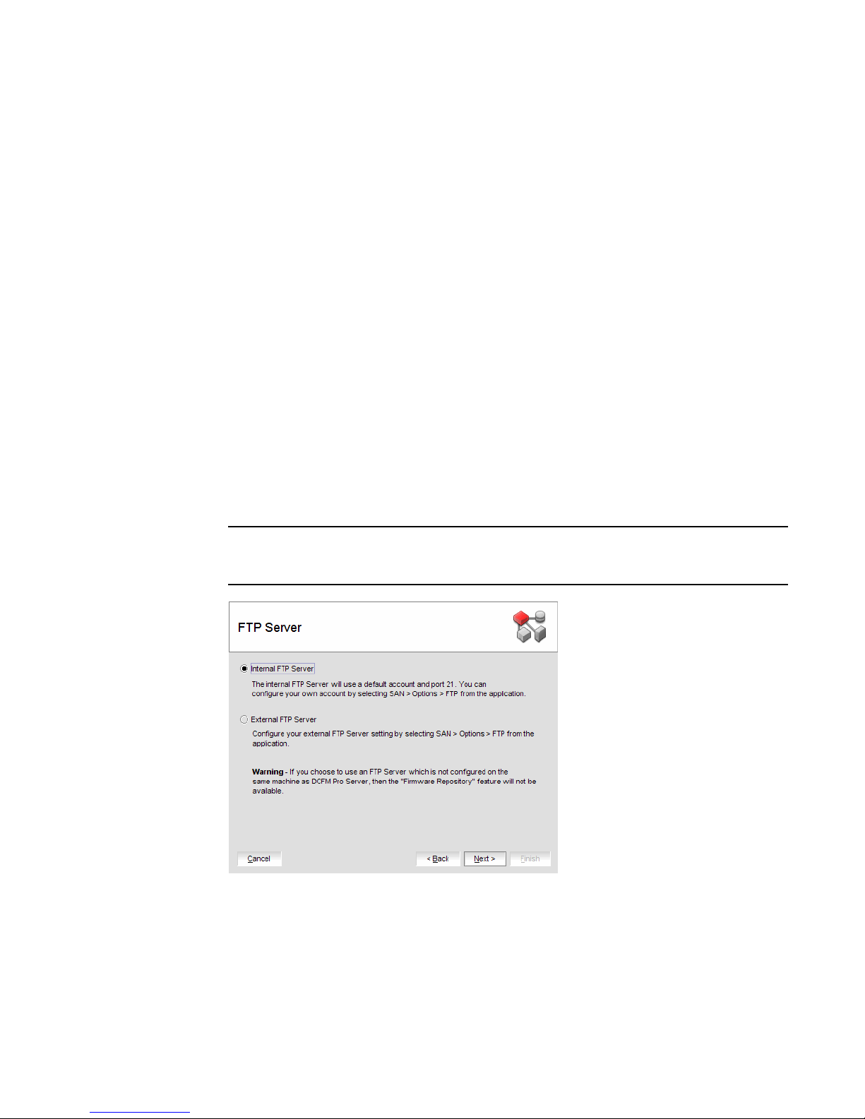
9. Select Internal FTP Server or External FTP Server on the FTP Server screen and click Next.
If port 21 is busy, a message displays. Click OK to close the message and continue. Once the
Management application is configured make sure port 21 is free and restart the Server to start
the FTP service.
NOTE
If you use an FTP Server that is not configured on the same machine as DCFM, the Firmware
Repository feature will not be available.
FIGURE 1 FTP Server screen
10 DCFM Installation, Migration, and Transition Guide
53-1001360-01
Page 27
Installing Professional edition on Windows systems
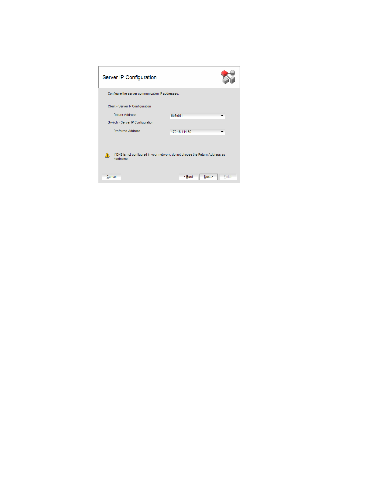
10. Complete the following steps on the Server IP Configuration screen.
FIGURE 2 Server IP Configuration screen
a. Select an address from the Client - Server IP Configuration Return Address list.
1
b. Select an address from the Switch - Server IP Configuration Preferred Address list.
If DNS is not configured for your network, do not select the ‘hostname’ option from either
the Return Address or Preferred Address list. Selecting the ‘hostname’ option prevents
clients and devices from communicating with the Server.
If you select a specific IP address from the Server IP Configuration screen and the selected
IP address changes, you will not be able to connect to the server. To change the IP
address, refer to “Configuring an explicit server IP address” on page 60.
c. Click Next.
DCFM Installation, Migration, and Transition Guide 11
53-1001360-01
Page 28
Installing Professional edition on Windows systems
1
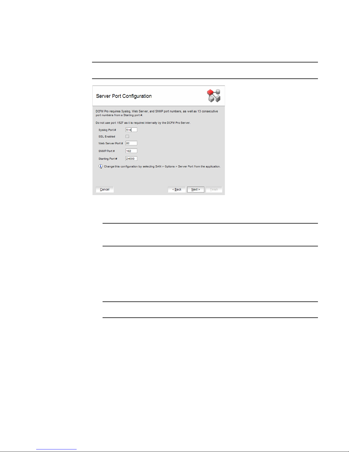
11. Complete the following steps on the Server Port Configuration screen.
NOTE
Do not use port 1527 for any of these port numbers. Port 1527 is used internally by the server.
FIGURE 3 Server Port Configuration screen
a. Enter a port number in the Syslog Port Number field (default is 514).
NOTE
If the default syslog port number is already in use, you will not receive any syslog
messages from the device.
b. Enable SSL by selecting the SSL Enabled check box.
c. Enter a port number in the Web Server Port Number field (default is 443 if SSL Enabled is
selected; otherwise, the default is 80).
d. Enter a port number in the SNMP Port Number field (default is 162).
e. Enter a port number in the Starting Port Number field (default is 24600).
NOTE
The server requires 13 consecutive free ports beginning with the starting port number.
f. Click Next.
If you enter a Syslog port number already in use, a message displays. Click OK to close the
message. Edit the Syslog port number and click Next.
If you enter a port number already in use, a Warning displays next to the associated port
number field. Edit that port number and click Next.
12. Verify your configuration information on the Server License Summary screen and click Next.
13. Select the Start DCFM Pro Client check box, if necessary, on the Start Server screen and click
Finish.
After all of the DCFM services are started, the Log In dialog box displays.
12 DCFM Installation, Migration, and Transition Guide
53-1001360-01
Page 29

Professional edition pre-installation requirements on UNIX systems
14. Enter your user name and password.
The defaults are Administrator and password, respectively.
15. Click Login.
16. Click OK on the Login Banner.
Professional edition pre-installation requirements on UNIX systems
• To avoid errors, close all instances of the application before beginning the installation or
uninstallation procedures.
If you still receive error messages after closing the application, enter the following commands:
#ps -ef | grep -i “” to list the process IDs
#kill -9 “<Process_ID>” where <Process_ID> is any Management application process
• Check for and install the latest Java patches for your operating system. DCFM requires
JRE 1.6.0. For the Solaris web site listing patch information, go to
http://java.sun.com/javase/downloads/index.jsp.
• (Solaris only) To use IPv6 on a server that is IPv4- and IPv6-enabled, complete the following
steps.
1
a. Open a command window.
b. Type ifconfig <Interface_Name> inet6 plumb up and press Enter.
c. Restart the Management server and client, if running.
If the IPv6 address is not configured properly, the client will show a "Server Not Available at
port 51511" message even though the server started successfully.
• Make sure that an X Server is available for display and is configured to permit X Client
applications to display from the host on which they are installing the DCFM Server (typically,
this simply requires that the systems console be present and running with a logged in user on
the X Server-based desktop session, such as KDE, GNOME, and so on).
If this is a headless unit with no console, refer to “Headless Pre-Installation Requirements” on
page 23.
• Make sure that the DISPLAY environment variable is correctly defined in the shell with a valid
value (for example, to display to the local console, export DISPLAY=:0.0, or to display to a
remote system that has an X Server running, export DISPLAY=<Remote_IP_address>:0.0).
You may also need to consider a firewall that might block the display to the X Server which
listens by default on TCP port 6000 on the remote host.
To display to a remote system you need to permit the remote display of the X Server by running
command xhost +IP, where IP is the IP address of the EFCM server host from the X-based
desktop of the remote system.
• Make sure you test the DISPLAY definition by running the command xterm, from the same shell
from which you run
should open.
install.bin. A new X terminal window to the destination X Server display
DCFM Installation, Migration, and Transition Guide 13
53-1001360-01
Page 30
Installing Professional edition on UNIX systems
1
Installing Professional edition on UNIX systems
1. Insert the installation DVD into the DVD-ROM drive and open the following file.
<DVD_Drive>\DCFMPro\<UNIX_Platform>\install.bin
2. Click Next on the Introduction screen.
3. Read the agreement on the License Agreement screen, select I accept the terms of the
License Agreement and click Next.
4. Select the usual location for your system’s application files (for example, opt\DCFMPro10_3_X)
on the Select Install Folder screen and click Next.
Do not install to the root directory (for example, /).
5. Review the displayed installation summary on the Pre-Installation Summary screen and click
Install.
6. Make sure the Launch DCFM Pro Configuration check box is selected (default) on the
Installation Complete screen, and click Done.
7. C l ic k Next on the Welcome screen.
8. Click No on the Copy Data and Settings screen and click Next.
To migrate data from a previous management application version, refer to Chapter 2,
“Migration”.
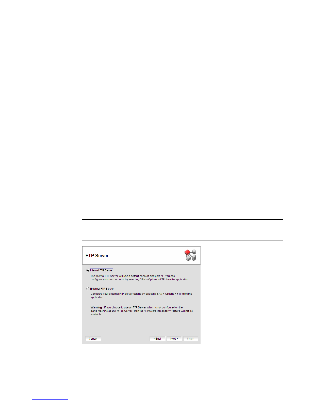
9. Select Internal FTP Server or External FTP Server on the FTP Server screen and click Next.
If port 21 is busy, a message displays. Click OK to close the message and continue. Once the
Management application is configured make sure port 21 is free and restart the Server to start
the FTP service.
NOTE
If you use an FTP Server that is not configured on the same machine as DCFM, the Firmware
Repository feature will not be available.
FIGURE 4 FTP Server screen
14 DCFM Installation, Migration, and Transition Guide
53-1001360-01
Page 31

Installing Professional edition on UNIX systems
10. Complete the following steps on the Server IP Configuration screen.
FIGURE 5 Server IP Configuration screen
a. Select an address from the Client - Server IP Configuration Return Address list.
1
b. Select an address from the Switch - Server IP Configuration Preferred Address list.
If DNS is not configured for your network, do not select the ‘hostname’ option from either
the Return Address or Preferred Address list. Selecting the ‘hostname’ option prevents
clients and devices from communicating with the Server.
If you select a specific IP address from the Server IP Configuration screen and the selected
IP address changes, you will not be able to connect to the server. To change the IP
address, refer to “Configuring an explicit server IP address” on page 60.
c. Click Next.
DCFM Installation, Migration, and Transition Guide 15
53-1001360-01
Page 32

Installing Professional edition on UNIX systems
1
11. Complete the following steps on the Server Port Configuration screen.
NOTE
Do not use port 1527 for any of these port numbers. Port 1527 is used internally by the server.
FIGURE 6 Server Port Configuration screen
a. Enter a port number in the Syslog Port Number field (default is 514).
NOTE
If the default syslog port number is already in use, you will not receive any syslog
messages from the device.
b. Enable SSL by selecting the SSL Enabled check box.
c. Enter a port number in the Web Server Port Number field (default is 443 if SSL Enabled is
selected; otherwise, the default is 80).
d. Enter a port number in the SNMP Port Number field (default is 162).
e. Enter a port number in the Starting Port Number field (default is 24600).
NOTE
The server requires 13 consecutive free ports beginning with the starting port number.
f. Click Next.
If you enter a Syslog port number already in use, a message displays. Click OK to close the
message. Edit the Syslog port number and click Next.
If you enter a port number already in use, a Warning displays next to the associated port
number field. Edit that port number and click Next.
12. Verify your configuration information on the Server License Summary screen and click Next.
13. Select the Start DCFM Pro Client check box, if necessary, on the Start Server screen and click
Finish.
After all of the DCFM services are started, the Log In dialog box displays.
16 DCFM Installation, Migration, and Transition Guide
53-1001360-01
Page 33

Professional edition pre-installation requirements on UNIX systems (headless)
14. Enter your user name and password.
The defaults are Administrator and password, respectively.
15. Click Login.
16. Click OK on the Login Banner.
1
Professional edition pre-installation requirements on UNIX systems
(headless)
An X Server display is required, even when performing a headless installation, to run the initial
configuration. Before you install DCFM, complete the following:
• Make sure that an X Server is available for display and is configured to permit X Client
applications to display from the host on which they are installing the DCFM Server (typically,
this simply requires that the systems console be present and running with a logged in user on
the X Server-based desktop session, such as KDE, GNOME, and so on).
The Display can be any host X Server (for example, DISPLAY can be set to display configuration
to another UNIX system that has an X based desktop).
• Make sure that the DISPLAY environment variable is correctly defined in the shell with a valid
value (for example, to display to the local console, export DISPLAY=:0.0, or to display to a
remote system that has an X Server running, export DISPLAY=
To display to a remote system you need to permit the remote display of the X Server by running
command xhost +IP, where IP is the IP address of the DCFM server host, on a local terminal
window of the X-based desktop of the remote system.
<Remote_IP_Address>:0.0).
You may also need to consider a firewall that might block the display to the X Server which
listens by default on TCP port 6000 on the remote host.
To display to a remote system you need to permit the remote display of the X Server by running
command xhost +IP, where IP is the IP address of the DCFM server host from the X based
desktop of the remote system.
• Make sure you test the DISPLAY definition by running the command xterm, from the same shell
from which you run install.bin. A new X terminal window to the destination X Server display
should open.
DCFM Installation, Migration, and Transition Guide 17
53-1001360-01
Page 34

Installing Professional edition on UNIX systems (headless)
1
Installing Professional edition on UNIX systems (headless)
To perform a headless installation through the CLI, complete the following steps.
1. Insert the installation DVD into the DVD-ROM drive and open the following file.
install.exe -i silent -DUSER_INSTALL_DIR="D:\Program Files\DCFM 10.3.0"
The installation starts in CLI mode.
2. Read the license agreement, type
3. Type the installation folder path and press Enter, if necessary.
4. Press Enter to accept the default installation path.
The pre-Installation summary displays.
5. Review the installation settings and press Enter to continue.
The application is installed.
6. Choose from the following after installation is complete:
Y and press Enter.
• Typ e 1 and press Enter to run Configuration immediately.
• Press Enter to run Configuration later.
A message indicating installation is complete displays.
7. Press Enter to complete the installation.
Troubleshooting the Linux installation
If you have completed all of the Pre-Installation requirements and you are still unable to install the
application, run the following commands on the host.
1. Go to <Install_Home>/ (the directory containing install.bin).
2. Execute
strace -f -F -v -s 1024 -o DCFM10install.txt ./install.bin.
3. Execute
4. Execute
5. Execute md5sum install.bin >> system.txt.
6. Execute
7. Execute
8. Execute env >> system.txt.
9. Execute
10. Execute
Send the
to Technical Support. This will help isolate the issue.
18 DCFM Installation, Migration, and Transition Guide
rpm -qa >> system.txt.
ps -elf >> system.txt.
df -k >> system.txt.
sh -c "xterm -e echo nothing >> system.txt 2>&1".
sh -c "DISPLAY=:0.0 xterm -e echo nothing >> system.txt 2>&1".
zip support1.zip DCFM10install.txt system.txt.
support1.zip file output from the above (containing install.txt and system.txt)
53-1001360-01
Page 35

Professional Plus trial installation
Professional Plus trial installation
Operating System Installation Procedures
Windows systems To install Enterprise trial, review the following section:
• “Professional Plus trial requirements” on page 19
• “Installing Professional Plus trial on Windows systems” on page 19
• “Installing the ODBC driver” on page 59
• “Configuring an explicit server IP address” on page 60
UNIX systems To install Enterprise trial, review the following sections:
• “Professional Plus trial requirements” on page 19
• “Professional Plus trial pre-installation requirements on UNIX systems” on page 23
• “Installing Professional Plus trial on UNIX systems” on page 24
• “Configuring an explicit server IP address” on page 60
• “Smart Card driver installation” on page 60
UNIX systems (Headless) To install Enterprise trial, review the following sections:
• “Professional Plus trial requirements” on page 19
• “Professional Plus trial pre-installation requirements on UNIX systems (headless)” on
page 27
• “Installing Professional Plus trial on UNIX systems (headless)” on page 28
• “Configuring an explicit server IP address” on page 60
• “Smart Card driver installation” on page 60
1
Professional Plus trial requirements
• Professional edition and Professional Plus trial cannot reside on the same host unless there
are two guest Operating System’s on the same host.
• Data collected during Professional Plus trial cannot be migrated back to Professional edition.
• After the Professional Plus trial, you will need to either roll back to Professional edition or
purchase Professional Plus or Enterprise edition.
• (IBM only) IBM-branded Professional Plus trial to IBM-branded Universal Key Enterprise edition
migration requires partially uninstalling the trial version and then copying the data and settings
to IBM-branded Universal Key Enterprise edition.
Installing Professional Plus trial on Windows systems
1. Insert the installation DVD into the DVD-ROM drive.
• If autorun is enabled, the DVD Index page launches automatically. Click the Professional
Plus Install link.
• If autorun is not enabled, open the following file:
<DVD_Drive>\DCFM\windows\install.exe
2. Click Next on the Introduction screen.
3. Read the agreement on the License Agreement screen, select I accept the terms of the
License Agreement and click Next.
DCFM Installation, Migration, and Transition Guide 19
53-1001360-01
Page 36

Installing Professional Plus trial on Windows systems
1
4. Select the usual location for your system’s application files (for example, D:\Program
Files\DCFM 10.3.X) on the Select Install Folder screen and click Next.
Do not install to the root directory (for example, C:\).
5. Review the displayed installation summary on the Pre-Installation Summary screen and click
Install.
6. Make sure the Launch DCFM Configuration check box is selected (default) on the Installation
Complete screen, and click Done.
7. C l ic k Next on the Welcome screen.
8. Select No on the Copy Data and Settings screen and then click Next.
To migrate data from a previous management application version, refer to Chapter 2,
“Migration”.
9. Click Next on the Server License screen.
10. Select Professional Plus on the Trial Editions screen and click Next.
11. Select Internal FTP Server or External FTP Server on the FTP Server screen and click Next.
If port 21 is busy, a message displays. Click OK to close the message and continue. Once the
Management application is configured make sure port 21 is free and restart the Server to start
the FTP service.
NOTE
If you use an FTP Server which is not configured on the same machine as DCFM, the Firmware
Repository feature will not be available.
FIGURE 7 FTP Server screen
20 DCFM Installation, Migration, and Transition Guide
53-1001360-01
Page 37

Installing Professional Plus trial on Windows systems
12. Complete the following steps on the Server IP Configuration screen.
FIGURE 8 Server IP Configuration screen
a. Select an address from the Client - Server IP Configuration Return Address list.
b. Select an address from the Switch - Server IP Configuration Preferred Address list.
1
If DNS is not configured for your network, do not select the ‘hostname’ option from either
the Return Address or Preferred Address list. Selecting the ‘hostname’ option prevents
clients and devices from communicating with the Server.
If you select a specific IP address from the Server IP Configuration screen and the selected
IP address changes, you will not be able to connect to the server. To change the IP
address, refer to “Configuring an explicit server IP address” on page 60.
c. Click Next.
DCFM Installation, Migration, and Transition Guide 21
53-1001360-01
Page 38

Installing Professional Plus trial on Windows systems
1
13. Complete the following steps on the Server Port Configuration screen.
NOTE
Do not use port 2638 for any of these port numbers. Port 2638 is used internally by the server.
24600
FIGURE 9 Server Port Configuration screen
a. Enter a port number in the Syslog Port Number field (default is 514).
NOTE
If the default syslog port number is already in use, you will not receive any syslog
messages from the device.
b. Enable SSL by selecting the SSL Enabled check box.
c. Enter a port number in the Web Server Port Number field (default is 443 if SSL Enabled is
selected; otherwise, the default is 80).
d. Enter a port number in the SNMP Port Number field (default is 162).
e. Enter a port number in the Starting Port Number field (default is 24600).
NOTE
The server requires 16 consecutive free ports beginning with the starting port number.
f. Click Next.
If you enter a Syslog port number already in use, a message displays. Click OK to close the
message. Edit the Syslog port number and click Next.
If you enter a port number already in use, a Warning displays next to the associated port
number field. Edit that port number and click Next.
14. Verify your configuration information on the Server License Summary screen and click Next.
15. Select the Start DCFM Client check box on the Start Server screen.
16. Click Finish.
After all of the selected services are started, the Log In dialog box displays.
22 DCFM Installation, Migration, and Transition Guide
53-1001360-01
Page 39

Professional Plus trial pre-installation requirements on UNIX systems
17. Enter your user name and password.
The defaults are Administrator and password, respectively.
18. Click Login.
19. Click OK on the Login Banner.
Professional Plus trial pre-installation requirements on UNIX systems
• To avoid errors, close all instances of the application before beginning the installation or
uninstallation procedures.
If you still receive error messages after closing the application, enter the following commands:
#ps -ef | grep -i “” to list the process IDs
#kill -9 “<Process_ID>” where <Process_ID> is any Management application process
• Check for and install the latest Java patches for your operating system. DCFM requires
JRE 1.6.0. For the Solaris web site listing patch information, go to
http://java.sun.com/javase/downloads/index.jsp.
• (Solaris only) To use IPv6 on a server that is IPv4- and IPv6-enabled, complete the following
steps.
1
a. Open a command window.
b. Type ifconfig <Interface_Name> inet6 plumb up and press Enter.
c. Restart the Management server and client, if running.
If the IPv6 address is not configured properly, the client will show a "Server Not Available at
port 51511" message even though the server started successfully.
• Make sure that an X Server is available for display and is configured to permit X Client
applications to display from the host on which they are installing the EFCM Server (typically,
this simply requires that the system console be present and running with a logged in user on
the X Server-based desktop session, such as KDE, GNOME, and so on).
If this is a headless unit with no console, refer to “Headless Pre-Installation Requirements” on
page 23.
• Make sure that the DISPLAY environment variable is correctly defined in the shell with a valid
value (for example, to display to the local console, export DISPLAY=:0.0, or to display to a
remote system that has an X Server running, export DISPLAY=<Remote_IP_address>:0.0).
You may also need to consider a firewall that might block the display to the X Server which
listens by default on TCP port 6000 on the remote host.
To display to a remote system you need to permit the remote display of the X Server by running
command xhost +IP, where IP is the IP address of the DCFM server host from the X-based
desktop of the remote system.
• Make sure you test the DISPLAY definition by running the command xterm from the same shell
from which you run
should open.
install.bin. A new X terminal window to the destination X Server display
DCFM Installation, Migration, and Transition Guide 23
53-1001360-01
Page 40

Installing Professional Plus trial on UNIX systems
1
Installing Professional Plus trial on UNIX systems
1. Insert the installation DVD into the DVD-ROM drive and open the following file.
<DVD_Drive>\DCFM\<UNIX_Platform>\install.bin
2. Click Next on the Introduction screen.
3. Read the agreement on the License Agreement screen, select I accept the terms of the
License Agreement and click Next.
4. Select the usual location for your system’s application files (for example, /opt/DCFM10_3_X)
on the Select Install Folder screen and click Next.
Do not install to the root directory (for example, /).
5. Review the displayed installation summary on the Pre-Installation Summary screen and click
Install.
6. Make sure the Launch DCFM Configuration check box is selected (default) on the Installation
Complete screen, and click Done.
7. C l ic k Next on the Welcome screen.
8. Select No on the Copy Data and Settings screen and then click Next.
To migrate data from a previous management application version, refer to Chapter 2,
“Migration”.
9. Click Next on the Server License screen.
10. Select Professional Plus on the Trial Editions screen and click Next.
11. Select Internal FTP Server or External FTP Server on the FTP Server screen and click Next.
If port 21 is busy, a message displays. Click OK to close the message and continue. Once the
Management application is configured make sure port 21 is free and restart the Server to start
the FTP service.
NOTE
If you use an FTP Server which is not configured on the same machine as DCFM, the Firmware
Repository feature will not be available.
FIGURE 10 FTP Server screen
24 DCFM Installation, Migration, and Transition Guide
53-1001360-01
Page 41

Installing Professional Plus trial on UNIX systems
12. Complete the following steps on the Server IP Configuration screen.
FIGURE 11 Server IP Configuration screen
a. Select an address from the Client - Server IP Configuration Return Address list.
b. Select an address from the Switch - Server IP Configuration Preferred Address list.
1
If DNS is not configured for your network, do not select the ‘hostname’ option from either
the Return Address or Preferred Address list. Selecting the ‘hostname’ option prevents
clients and devices from communicating with the Server.
If you select a specific IP address from the Server IP Configuration screen and the selected
IP address changes, you will not be able to connect to the server. To change the IP
address, refer to “Configuring an explicit server IP address” on page 60.
c. Click Next.
DCFM Installation, Migration, and Transition Guide 25
53-1001360-01
Page 42

Installing Professional Plus trial on UNIX systems
1
13. Complete the following steps on the Server Port Configuration screen.
NOTE
Do not use port 2638 for any of these port numbers. Port 2638 is used internally by the server.
FIGURE 12 Server Port Configuration screen
24600
a. Enter a port number in the Syslog Port Number field (default is 514).
NOTE
If the default syslog port number is already in use, you will not receive any syslog
messages from the device.
b. Enable SSL by selecting the SSL Enabled check box.
c. Enter a port number in the Web Server Port Number field (default is 443 if SSL Enabled is
selected; otherwise, the default is 80).
d. Enter a port number in the SNMP Port Number field (default is 162).
e. Enter a port number in the Starting Port Number field (default is 24600).
NOTE
The server requires 16 consecutive free ports beginning with the starting port number.
f. Click Next.
If you enter a Syslog port number already in use, a message displays. Click OK to close the
message. Edit the Syslog port number and click Next.
If you enter a port number already in use, a Warning displays next to the associated port
number field. Edit that port number and click Next.
14. Verify your configuration information on the Server License Summary screen and click Next.
15. Select the Start DCFM Client check box on the Start Server screen.
16. Click Finish.
After all of the selected services are started, the Log In dialog box displays.
26 DCFM Installation, Migration, and Transition Guide
53-1001360-01
Page 43

Professional Plus trial pre-installation requirements on UNIX systems (headless)
17. Enter your user name and password.
The defaults are Administrator and password, respectively. If you migrated from a previous
release, your user name and password do not change.
18. Click Login.
19. Click OK on the Login Banner.
Professional Plus trial pre-installation requirements on UNIX systems
(headless)
An X Server display is required, even when performing a headless installation, to run the initial
configuration. Before you install DCFM, complete the following:
• Make sure that an X Server is available for display and is configured to permit X Client
applications to display from the host on which they are installing the DCFM Server (typically,
this simply requires that the system console be present and running with a logged in user on
the X Server-based desktop session, such as KDE, GNOME, and so on).
The Display can be any host X Server (for example, DISPLAY can be set to display configuration
to another UNIX system that has an X based desktop).
1
• Make sure that the DISPLAY environment variable is correctly defined in the shell with a valid
value (for example, to display to the local console, export DISPLAY=:0.0, or to display to a
remote system that has an X Server running, export DISPLAY=
To display to a remote system you need to permit the remote display of the X Server by running
command xhost +IP, where IP is the IP address of the DCFM server host, on a local terminal
window of the X-based desktop of the remote system.
You may also need to consider a firewall that might block the display to the X Server which
listens by default on TCP port 6000 on the remote host.
To display to a remote system you need to permit the remote display of the X Server by running
command xhost +IP, where IP is the IP address of the DCFM server host from the X based
desktop of the remote system.
<Remote_IP_Address>:0.0).
• Make sure you test the DISPLAY definition by running the command xterm from the same shell
from which you run
should open.
install.bin. A new X terminal window to the destination X Server display
DCFM Installation, Migration, and Transition Guide 27
53-1001360-01
Page 44

Installing Professional Plus trial on UNIX systems (headless)
1
Installing Professional Plus trial on UNIX systems (headless)
To perform a headless installation through the CLI, complete the following steps.
1. Insert the installation DVD into the DVD-ROM drive and open the following file.
install.exe -i silent -DUSER_INSTALL_DIR="D:\Program Files\DCFM 10.3.0"
The installation starts in CLI mode.
2. Read the license agreement, type
3. Type the installation folder path and press Enter, if necessary.
4. Press Enter to accept the default installation path.
The pre-Installation summary displays.
5. Review the installation settings and press Enter to continue.
The application is installed.
6. Choose from the following after installation is complete:
Y and press Enter.
• Type 1 and press Enter to run Configuration immediately.
• Press Enter to run Configuration later.
A message indicating installation is complete displays.
7. Press Enter to complete the installation.
28 DCFM Installation, Migration, and Transition Guide
53-1001360-01
Page 45

Professional Plus edition installation
Professional Plus edition installation
Operating System Installation Procedures
Windows systems To install Professional Plus edition, review the following sections:
• “Installing Enterprise edition on Windows systems” on page 49
• “Installing the ODBC driver” on page 59
• “Configuring an explicit server IP address” on page 60
UNIX systems To install Professional Plus edition, review the following sections:
• “Enterprise edition pre-installation requirements on UNIX systems” on page 53
• “Installing Enterprise edition on UNIX systems” on page 54
• “Configuring an explicit server IP address” on page 60
• “Smart Card driver installation” on page 60
UNIX systems (Headless) To install Professional Plus edition, review the following sections:
• “Enterprise edition pre-installation requirements on UNIX systems (headless)” on page 58
• “Installing Enterprise edition on UNIX systems (headless)” on page 59
• “Configuring an explicit server IP address” on page 60
• “Smart Card driver installation” on page 60
1
Installing Professional Plus edition on Windows systems
1. Insert the installation DVD into the DVD-ROM drive.
• If autorun is enabled, the DVD Index page launches automatically. Click the Professional
Plus Install link.
• If autorun is not enabled, open the following file:
<DVD_Drive>\DCFM\windows\install.exe
2. Click Next on the Introduction screen.
3. Read the agreement on the License Agreement screen, select I accept the terms of the
License Agreement and click Next.
4. Select the usual location for your system’s application files (for example, D:\Program
Files\DCFM 10.3.X) on the Select Install Folder screen and click Next.
Do not install to the root directory (for example, C:\).
5. Review the displayed installation summary on the Pre-Installation Summary screen and click
Install.
6. Make sure the Launch DCFM Configuration check box is selected (default) on the Installation
Complete screen, and click Done.
7. C l ic k Next on the Welcome screen.
8. Select No on the Copy Data and Settings screen and then click Next.
DCFM Installation, Migration, and Transition Guide 29
53-1001360-01
Page 46

Installing Professional Plus edition on Windows systems
1
9. Enter the serial number (on the DVD jewel case) and license key (on the Key Certificate) on the
Server License screen and click Next.
The License Key field is not case-sensitive.
10. Select Internal FTP Server or External FTP Server on the FTP Server screen and click Next.
If port 21 is busy, a message displays. Click OK to close the message and continue. Once the
Management application is configured make sure port 21 is free and restart the Server to start
the FTP service.
NOTE
If you use an FTP Server which is not configured on the same machine as DCFM, the Firmware
Repository feature will not be available.
FIGURE 13 FTP Server screen
30 DCFM Installation, Migration, and Transition Guide
53-1001360-01
Page 47

Installing Professional Plus edition on Windows systems
11. Complete the following steps on the Server IP Configuration screen.
FIGURE 14 Server IP Configuration screen
a. Select an address from the Client - Server IP Configuration Return Address list.
b. Select an address from the Switch - Server IP Configuration Preferred Address list.
1
If DNS is not configured for your network, do not select the ‘hostname’ option from either
the Return Address or Preferred Address list. Selecting the ‘hostname’ option prevents
clients and devices from communicating with the Server.
If you select a specific IP address from the Server IP Configuration screen and the selected
IP address changes, you will not be able to connect to the server. To change the IP
address, refer to “Configuring an explicit server IP address” on page 60.
c. Click Next.
DCFM Installation, Migration, and Transition Guide 31
53-1001360-01
Page 48

Installing Professional Plus edition on Windows systems
1
12. Complete the following steps on the Server Port Configuration screen.
NOTE
Do not use port 2638 for any of these port numbers. Port 2638 is used internally by the server.
24600
FIGURE 15 Server Port Configuration screen
a. Enter a port number in the Syslog Port Number field (default is 514).
NOTE
If the default syslog port number is already in use, you will not receive any syslog
messages from the device.
b. Enable SSL by selecting the SSL Enabled check box.
c. Enter a port number in the Web Server Port Number field (default is 443 if SSL Enabled is
selected; otherwise, the default is 80).
d. Enter a port number in the SNMP Port Number field (default is 162).
e. Enter a port number in the Starting Port Number field (default is 24600).
NOTE
The server requires 16 consecutive free ports beginning with the starting port number.
f. Click Next.
If you enter a Syslog port number already in use, a message displays. Click OK to close the
message. Edit the Syslog port number and click Next.
If you enter a port number already in use, a Warning displays next to the associated port
number field. Edit that port number and click Next.
13. Verify your configuration and license information on the Server License Summary screen and
click Next.
14. Select the Start DCFM Client check box on the Start Server screen.
15. Click Finish.
After all of the selected services are started, the Log In dialog box displays.
32 DCFM Installation, Migration, and Transition Guide
53-1001360-01
Page 49

Professional Plus edition pre-installation requirements on UNIX systems
16. Enter your user name and password.
The defaults are Administrator and password, respectively. If you migrated from a previous
release, your user name and password do not change.
17. Click Login.
18. Click OK on the Login Banner.
Professional Plus edition pre-installation requirements on UNIX
systems
• To avoid errors, close all instances of the application before beginning the installation or
uninstallation procedures.
If you still receive error messages after closing the application, enter the following commands:
#ps -ef | grep -i “” to list the process IDs
#kill -9 “<Process_ID>” where <Process_ID> is any Management application process
• Check for and install the latest Java patches for your operating system. The Management
application requires JRE 1.6.0. For the Solaris web site listing patch information, go to
http://java.sun.com/javase/downloads/index.jsp.
• (Solaris only) To use IPv6 on a server that is IPv4 and IPv6 enabled, complete the following
steps.
1
a. Open a command window.
b. Type ifconfig <Interface_Name> inet6 plumb up and press Enter.
c. Restart the Management server and client, if running.
If the IPv6 address is not configured properly, the client will show a "Server Not Available at
port 51511" message even though the server started successfully.
• Make sure that an X Server is available for display and is configured to permit X Client
applications to display from the host on which they are installing the EFCM Server (typically,
this simply requires that the system console be present and running with a logged in user on
the X Server-based desktop session, such as KDE, GNOME, and so on).
If this is a headless unit with no console, refer to “Headless Pre-Installation Requirements” on
page 23.
• Make sure that the DISPLAY environment variable is correctly defined in the shell with a valid
value (for example, to display to the local console, export DISPLAY=:0.0, or to display to a
remote system that has an X Server running, export DISPLAY=<Remote_IP_address>:0.0).
You may also need to consider a firewall that might block the display to the X Server which
listens by default on TCP port 6000 on the remote host.
To display to a remote system you need to permit the remote display of the X Server by running
command xhost +IP, where IP is the IP address of the DCFM server host, on a local terminal
window of the X-based desktop of the remote system.
• Make sure you test the DISPLAY definition by running the command xterm from the same shell
from which you run
should open.
install.bin. A new X terminal window to the destination X Server display
DCFM Installation, Migration, and Transition Guide 33
53-1001360-01
Page 50

Installing Professional Plus edition on UNIX systems
1
Installing Professional Plus edition on UNIX systems
1. Insert the installation DVD into the DVD-ROM drive and open the following file.
<DVD_Drive>\DCFM\<UNIX_Platform>\install.bin
2. Click Next on the Introduction screen.
3. Read the agreement on the License Agreement screen, select I accept the terms of the
License Agreement and click Next.
4. Select the usual location for your system’s application files (for example, /opt/DCFM10_3_X)
on the Select Install Folder screen and click Next.
Do not install to the root directory (for example, /).
5. Review the displayed installation summary on the Pre-Installation Summary screen and click
Install.
6. Make sure the Launch DCFM Configuration check box is selected (default) on the Installation
Complete screen, and click Done.
7. C l ic k Next on the Welcome screen.
8. Select No on the Copy Data and Settings screen and then click Next.
To migrate data from a previous management application version, refer to Chapter 2,
“Migration”.
9. Enter the serial number (on the DVD jewel case) and license key (on the Key Certificate) on the
Server License screen and click Next.
The License Key field is not case-sensitive.
10. Select Internal FTP Server or External FTP Server on the FTP Server screen and click Next.
If port 21 is busy, a message displays. Click OK to close the message and continue. Once the
Management application is configured make sure port 21 is free and restart the Server to start
the FTP service.
NOTE
If you use an FTP Server which is not configured on the same machine as DCFM, the Firmware
Repository feature will not be available.
FIGURE 16 FTP Server screen
34 DCFM Installation, Migration, and Transition Guide
53-1001360-01
Page 51

Installing Professional Plus edition on UNIX systems
11. Complete the following steps on the Server IP Configuration screen.
FIGURE 17 Server IP Configuration screen
a. Select an address from the Client - Server IP Configuration Return Address list.
b. Select an address from the Switch - Server IP Configuration Preferred Address list.
1
If DNS is not configured for your network, do not select the ‘hostname’ option from either
the Return Address or Preferred Address list. Selecting the ‘hostname’ option prevents
clients and devices from communicating with the Server.
If you select a specific IP address from the Server IP Configuration screen and the selected
IP address changes, you will not be able to connect to the server. To change the IP
address, refer to “Configuring an explicit server IP address” on page 60.
c. Click Next.
DCFM Installation, Migration, and Transition Guide 35
53-1001360-01
Page 52

Installing Professional Plus edition on UNIX systems
1
12. Complete the following steps on the Server Port Configuration screen.
NOTE
Do not use port 2638 for any of these port numbers. Port 2638 is used internally by the server.
24600
FIGURE 18 Server Port Configuration screen
a. Enter a port number in the Syslog Port Number field (default is 514).
NOTE
If the default syslog port number is already in use, you will not receive any syslog
messages from the device.
b. Enable SSL by selecting the SSL Enabled check box.
c. Enter a port number in the Web Server Port Number field (default is 443 if SSL Enabled is
selected; otherwise, the default is 80).
d. Enter a port number in the SNMP Port Number field (default is 162).
e. Enter a port number in the Starting Port Number field (default is 24600).
NOTE
The server requires 16 consecutive free ports beginning with the starting port number.
f. Click Next.
If you enter a Syslog port number already in use, a message displays. Click OK to close the
message. Edit the Syslog port number and click Next.
If you enter a port number already in use, a Warning displays next to the associated port
number field. Edit that port number and click Next.
13. Verify your configuration and license information on the Server License Summary screen and
click Next.
14. Select the Start Client check box, if necessary, on the Start Server screen and click Finish.
After all of the DCFM services are started, the Log In dialog box displays.
36 DCFM Installation, Migration, and Transition Guide
53-1001360-01
Page 53

Professional Plus edition pre-installation requirements on UNIX systems (headless)
15. Enter your user name and password.
The defaults are Administrator and password, respectively. If you migrated from a previous
release, your user name and password do not change.
16. Click Login.
17. Click OK on the Login Banner.
Professional Plus edition pre-installation requirements on UNIX
systems (headless)
An X Server display is required, even when performing a headless installation, to run the initial
configuration. Before you install DCFM, complete the following:
• Make sure that an X Server is available for display and is configured to permit X Client
applications to display from the host on which they are installing the DCFM Server (typically,
this simply requires that the system console be present and running with a logged in user on
the X Server-based desktop session, such as KDE, GNOME, and so on).
The Display can be any host X Server (for example, DISPLAY can be set to display configuration
to another UNIX system that has an X-based desktop).
1
• Make sure that the DISPLAY environment variable is correctly defined in the shell with a valid
value (for example, to display to the local console, export DISPLAY=:0.0, or to display to a
remote system that has an X Server running, export DISPLAY=
To display to a remote system you need to permit the remote display of the X Server by running
command xhost +IP, where IP is the IP address of the DCFM server host, on a local terminal
window of the X-based desktop of the remote system.
You may also need to consider a firewall that might block the display to the X Server which
listens by default on TCP port 6000 on the remote host.
To display to a remote system you need to permit the remote display of the X Server by running
command xhost +IP, where IP is the IP address of the DCFM server host from the X based
desktop of the remote system.
<Remote_IP_Address>:0.0).
• Make sure you test the DISPLAY definition by running the command xterm from the same shell
from which you run
should open.
install.bin. A new X terminal window to the destination X Server display
DCFM Installation, Migration, and Transition Guide 37
53-1001360-01
Page 54

Installing Professional Plus edition on UNIX systems (headless)
1
Installing Professional Plus edition on UNIX systems (headless)
To perform a headless installation through the CLI, complete the following steps.
1. Insert the installation DVD into the DVD ROM drive and open the following file.
install.exe -i silent -DUSER_INSTALL_DIR="D:\Program Files\DCFM 10.3.0"
The installation starts in CLI mode.
2. Read the license agreement, type
3. Type the installation folder path and press Enter, if necessary.
4. Press Enter to accept the default installation path.
The pre-Installation summary displays.
5. Review the installation settings and press Enter to continue.
The application is installed.
6. Choose from the following after installation is complete:
Y and press Enter.
• Type 1 and press Enter to run Configuration immediately.
• Press Enter to run Configuration later.
A message indicating installation is complete displays.
7. Press Enter to complete the installation.
38 DCFM Installation, Migration, and Transition Guide
53-1001360-01
Page 55

Enterprise trial installation
Operating System Installation Procedures
Windows systems To install Enterprise trial, review the following sections:
• “Enterprise trial requirements” on page 39
• “Installing Enterprise trial on Windows systems” on page 39
• “Installing the ODBC driver” on page 59
• “Configuring an explicit server IP address” on page 60
UNIX systems To install Enterprise trial, review the following sections:
• “Enterprise trial requirements” on page 39
• “Enterprise trial pre-installation requirements on UNIX systems” on page 43
• “Installing Enterprise trial on UNIX systems” on page 44
• “Configuring an explicit server IP address” on page 60
• “Smart Card driver installation” on page 60
UNIX systems (Headless) To install Enterprise trial, review the following sections:
• “Enterprise trial requirements” on page 39
• “Enterprise trial pre-installation requirements on UNIX systems (headless)” on page 47
• “Installing Enterprise trial on UNIX systems (headless)” on page 48
• “Configuring an explicit server IP address” on page 60
• “Smart Card driver installation” on page 60
Enterprise trial installation
1
Enterprise trial requirements
• Professional edition and Enterprise trial cannot reside on the same host unless there are
two guest OS’s on the same host.
• Data collected during Enterprise trial cannot be migrated back to Professional edition.
• After the Enterprise trial, you will need to either roll back to Professional edition or purchase
Enterprise edition.
Installing Enterprise trial on Windows systems
1. Insert the installation DVD into the DVD-ROM drive.
• If autorun is enabled, the DVD Index page launches automatically. Click the Enterprise
Install link.
• If autorun is not enabled, open the following file:
<DVD_Drive>\DCFM\windows\install.exe
2. Click Next on the Introduction screen.
3. Read the agreement on the License Agreement screen, select I accept the terms of the
License Agreement and click Next.
4. Select the usual location for your system’s application files (for example, D:\Program
Files\DCFM 10.3.X) on the Select Install Folder screen and click Next.
Do not install to the root directory (for example, C:\).
5. Review the displayed installation summary on the Pre-Installation Summary screen and click
Install.
DCFM Installation, Migration, and Transition Guide 39
53-1001360-01
Page 56

Installing Enterprise trial on Windows systems
1
6. Make sure the Launch DCFM Configuration check box is selected (default) on the Installation
Complete screen, and click Done.
7. C l ic k Next on the Welcome screen.
8. Select No on the Copy Data and Settings screen and then click Next.
To migrate data from a previous management application version, refer to Chapter 2,
“Migration”.
9. Click Next on the Server License screen.
10. Select Enterprise on the Trial Editions screen and click Next.
11. Select Internal FTP Server or External FTP Server on the FTP Server screen and click Next.
If port 21 is busy, a message displays. Click OK to close the message and continue. Once the
Management application is configured make sure port 21 is free and restart the Server to start
the FTP service.
NOTE
If you use an FTP Server which is not configured on the same machine as DCFM, the Firmware
Repository feature will not be available.
FIGURE 19 FTP Server screen
40 DCFM Installation, Migration, and Transition Guide
53-1001360-01
Page 57

Installing Enterprise trial on Windows systems
12. Complete the following steps on the Server IP Configuration screen.
FIGURE 20 Server IP Configuration screen
a. Select an address from the Client - Server IP Configuration Return Address list.
b. Select an address from the Switch - Server IP Configuration Preferred Address list.
1
If DNS is not configured for your network, do not select the ‘hostname’ option from either
the Return Address or Preferred Address list. Selecting the ‘hostname’ option prevents
clients and devices from communicating with the Server.
If you select a specific IP address from the Server IP Configuration screen and the selected
IP address changes, you will not be able to connect to the server. To change the IP
address, refer to “Configuring an explicit server IP address” on page 60.
c. Click Next.
DCFM Installation, Migration, and Transition Guide 41
53-1001360-01
Page 58

Installing Enterprise trial on Windows systems
1
13. Complete the following steps on the Server Port Configuration screen.
NOTE
Do not use port 2638 for any of these port numbers. Port 2638 is used internally by the server.
FIGURE 21 Server Port Configuration screen
24600
a. Enter a port number in the Syslog Port Number field (default is 514).
NOTE
If the default syslog port number is already in use, you will not receive any syslog
messages from the device.
b. Enable SSL by selecting the SSL Enabled check box.
c. Enter a port number in the Web Server Port Number field (default is 443 if SSL Enabled is
selected; otherwise, the default is 80).
d. Enter a port number in the SNMP Port Number field (default is 162).
e. Enter a port number in the Starting Port Number field (default is 24600).
NOTE
The server requires 16 consecutive free ports beginning with the starting port number.
f. Click Next.
If you enter a Syslog port number already in use, a message displays. Click OK to close the
message. Edit the Syslog port number and click Next.
If you enter a port number already in use, a Warning displays next to the associated port
number field. Edit that port number and click Next.
14. Select one of the following options on the SAN Size screen (for Pure Fabric OS fabrics only):
• Small (managing up to 2000 ports, 1-20 domains)
• Medium (managing up to 5000 ports, 21-60 domains)
• Large (managing up to 9000 ports, 61-120 domains)
15. Click Next.
16. Verify your configuration information on the Server License Summary screen and click Next.
42 DCFM Installation, Migration, and Transition Guide
53-1001360-01
Page 59

Enterprise trial pre-installation requirements on UNIX systems
17. Select the Start DCFM Client check box on the Start Server screen.
18. Click Finish.
After all of the selected services are started, the Log In dialog box displays.
19. Enter your user name and password.
The defaults are Administrator and password, respectively.
20. Click Login.
21. Click OK on the Login Banner.
Enterprise trial pre-installation requirements on UNIX systems
• To avoid errors, close all instances of the application before beginning the installation or
uninstallation procedures.
If you still receive error messages after closing the application, enter the following commands:
#ps -ef | grep -i “” to list the process IDs
#kill -9 “<Process_ID>” where <Process_ID> is any Management application process
• Check for and install the latest Java patches for your operating system. DCFM requires
JRE 1.6.0. For the Solaris web site listing patch information, go to
http://java.sun.com/javase/downloads/index.jsp.
• (Solaris only) To use IPv6 on a server that is IPv4- and IPv6-enabled, complete the following
steps.
1
a. Open a command window.
b. Type ifconfig <Interface_Name> inet6 plumb up and press Enter.
c. Restart the Management server and client, if running.
If the IPv6 address is not configured properly, the client will show a "Server Not Available at
port 51511" message even though the server started successfully.
• Make sure that an X Server is available for display and is configured to permit X Client
applications to display from the host on which they are installing the EFCM Server (typically,
this simply requires that the system console be present and running with a logged in user on
the X Server-based desktop session, such as KDE, GNOME, and so on).
If this is a headless unit with no console, refer to “Headless Pre-Installation Requirements” on
page 23.
• Make sure that the DISPLAY environment variable is correctly defined in the shell with a valid
value (for example, to display to the local console, export DISPLAY=:0.0, or to display to a
remote system that has an X Server running, export DISPLAY=<Remote_IP_address>:0.0).
You may also need to consider a firewall that might block the display to the X Server which
listens by default on TCP port 6000 on the remote host.
To display to a remote system you need to permit the remote display of the X Server by running
command xhost +IP, where IP is the IP address of the DCFM server host from the X-based
desktop of the remote system.
• Make sure you test the DISPLAY definition by running the command xterm from the same shell
from which you run
should open.
install.bin. A new X terminal window to the destination X Server display
DCFM Installation, Migration, and Transition Guide 43
53-1001360-01
Page 60

Installing Enterprise trial on UNIX systems
1
Installing Enterprise trial on UNIX systems
1. Insert the installation DVD into the DVD-ROM drive and open the following file.
<DVD_Drive>\DCFM\<UNIX_Platform>\install.bin
2. Click Next on the Introduction screen.
3. Read the agreement on the License Agreement screen, select I accept the terms of the
License Agreement and click Next.
4. Select the usual location for your system’s application files (for example, /opt/DCFM10_3_X)
on the Select Install Folder screen and click Next.
Do not install to the root directory (for example, /).
5. Review the displayed installation summary on the Pre-Installation Summary screen and click
Install.
6. Make sure the Launch DCFM Configuration check box is selected (default) on the Installation
Complete screen, and click Done.
7. C l ic k Next on the Welcome screen.
8. Select No on the Copy Data and Settings screen and then click Next.
To migrate data from a previous management application version, refer to Chapter 2,
“Migration”.
9. Click Next on the Server License screen.
10. Select Enterprise on the Trial Editions screen and click Next.
11. Select Internal FTP Server or External FTP Server on the FTP Server screen and click Next.
If port 21 is busy, a message displays. Click OK to close the message and continue. Once the
Management application is configured make sure port 21 is free and restart the Server to start
the FTP service.
NOTE
If you use an FTP Server which is not configured on the same machine as DCFM, the Firmware
Repository feature will not be available.
FIGURE 22 FTP Server screen
44 DCFM Installation, Migration, and Transition Guide
53-1001360-01
Page 61

Installing Enterprise trial on UNIX systems
12. Complete the following steps on the Server IP Configuration screen.
FIGURE 23 Server IP Configuration screen
a. Select an address from the Client - Server IP Configuration Return Address list.
b. Select an address from the Switch - Server IP Configuration Preferred Address list.
1
If DNS is not configured for your network, do not select the ‘hostname’ option from either
the Return Address or Preferred Address list. Selecting the ‘hostname’ option prevents
clients and devices from communicating with the Server.
If you select a specific IP address from the Server IP Configuration screen and the selected
IP address changes, you will not be able to connect to the server. To change the IP
address, refer to “Configuring an explicit server IP address” on page 60.
c. Click Next.
DCFM Installation, Migration, and Transition Guide 45
53-1001360-01
Page 62

Installing Enterprise trial on UNIX systems
1
13. Complete the following steps on the Server Port Configuration screen.
NOTE
Do not use port 2638 for any of these port numbers. Port 2638 is used internally by the server.
FIGURE 24 Server Port Configuration screen
24600
a. Enter a port number in the Syslog Port Number field (default is 514).
NOTE
If the default syslog port number is already in use, you will not receive any syslog
messages from the device.
b. Enable SSL by selecting the SSL Enabled check box.
c. Enter a port number in the Web Server Port Number field (default is 443 if SSL Enabled is
selected; otherwise, the default is 80).
d. Enter a port number in the SNMP Port Number field (default is 162).
e. Enter a port number in the Starting Port Number field (default is 24600).
NOTE
The server requires 16 consecutive free ports beginning with the starting port number.
f. Click Next.
If you enter a Syslog port number already in use, a message displays. Click OK to close the
message. Edit the Syslog port number and click Next.
If you enter a port number already in use, a Warning displays next to the associated port
number field. Edit that port number and click Next.
14. Select one of the following options on the SAN Size screen (for Pure Fabric OS fabrics only):
• Small (managing up to 2000 ports, 1-20 domains)
• Medium (managing up to 5000 ports, 21-60 domains)
• Large (managing up to 9000 ports, 61-120 domains)
15. Click Next.
16. Verify your configuration information on the Server License Summary screen and click Next.
46 DCFM Installation, Migration, and Transition Guide
53-1001360-01
Page 63

Enterprise trial pre-installation requirements on UNIX systems (headless)
17. Select the Start DCFM Client check box on the Start Server screen.
18. Click Finish.
After all of the selected services are started, the Log In dialog box displays.
19. Enter your user name and password.
The defaults are Administrator and password, respectively.
20. Click Login.
21. Click OK on the Login Banner.
Enterprise trial pre-installation requirements on UNIX systems
(headless)
An X Server display is required, even when performing a headless installation, to run the initial
configuration. Before you install DCFM, complete the following:
• Make sure that an X Server is available for display and is configured to permit X Client
applications to display from the host on which they are installing the DCFM Server (typically,
this simply requires that the system console be present and running with a logged in user on
the X Server-based desktop session, such as KDE, GNOME, and so on).
The Display can be any host X Server (for example, DISPLAY can be set to display configuration
to another UNIX system that has an X based desktop).
1
• Make sure that the DISPLAY environment variable is correctly defined in the shell with a valid
value (for example, to display to the local console, export DISPLAY=:0.0, or to display to a
remote system that has an X Server running, export DISPLAY=
To display to a remote system you need to permit the remote display of the X Server by running
command xhost +IP, where IP is the IP address of the DCFM server host, on a local terminal
window of the X-based desktop of the remote system.
You may also need to consider a firewall that might block the display to the X Server which
listens by default on TCP port 6000 on the remote host.
To display to a remote system you need to permit the remote display of the X Server by running
command xhost +IP, where IP is the IP address of the DCFM server host from the X based
desktop of the remote system.
<Remote_IP_Address>:0.0).
• Make sure you test the DISPLAY definition by running the command xterm from the same shell
from which you run
should open.
install.bin. A new X terminal window to the destination X Server display
DCFM Installation, Migration, and Transition Guide 47
53-1001360-01
Page 64

Installing Enterprise trial on UNIX systems (headless)
1
Installing Enterprise trial on UNIX systems (headless)
To perform a headless installation through the CLI, complete the following steps.
1. Insert the installation DVD into the DVD-ROM drive and open the following file.
install.exe -i silent -DUSER_INSTALL_DIR="D:\Program Files\DCFM 10.1.0"
The installation starts in CLI mode.
2. Read the license agreement, type
3. Type the installation folder path and press Enter, if necessary.
4. Press Enter to accept the default installation path.
The pre-Installation summary displays.
5. Review the installation settings and press Enter to continue.
The application is installed.
6. Choose from the following after installation is complete:
Y and press Enter.
• Type 1 and press Enter to run Configuration immediately.
• Press Enter to run Configuration later.
A message indicating installation is complete displays.
7. Press Enter to complete the installation.
48 DCFM Installation, Migration, and Transition Guide
53-1001360-01
Page 65

Enterprise edition installation
Enterprise edition installation
Operating System Installation Procedures
Windows systems To install Enterprise edition, review the following sections:
• “Installing Enterprise edition on Windows systems” on page 49
• “Installing the ODBC driver” on page 59
• “Configuring an explicit server IP address” on page 60
UNIX systems To install Enterprise edition, review the following sections:
• “Enterprise edition pre-installation requirements on UNIX systems” on page 53
• “Installing Enterprise edition on UNIX systems” on page 54
• “Configuring an explicit server IP address” on page 60
• “Smart Card driver installation” on page 60
UNIX systems (Headless) To install Enterprise edition, review the following sections:
• “Enterprise edition pre-installation requirements on UNIX systems (headless)” on page 58
• “Installing Enterprise edition on UNIX systems (headless)” on page 59
• “Configuring an explicit server IP address” on page 60
• “Smart Card driver installation” on page 60
1
Installing Enterprise edition on Windows systems
1. Insert the installation DVD into the DVD-ROM drive.
• If autorun is enabled, the DVD Index page launches automatically. Click the Enterprise
Install link.
• If autorun is not enabled, open the following file:
<DVD_Drive>\DCFM\windows\install.exe
2. Click Next on the Introduction screen.
3. Read the agreement on the License Agreement screen, select I accept the terms of the
License Agreement and click Next.
4. Select the usual location for your system’s application files (for example, D:\Program
Files\DCFM 10.3.X) on the Select Install Folder screen and click Next.
Do not install to the root directory (for example, C:\).
5. Review the displayed installation summary on the Pre-Installation Summary screen and click
Install.
6. Make sure the Launch DCFM Configuration check box is selected (default) on the Installation
Complete screen, and click Done.
7. C l ic k Next on the Welcome screen.
8. Select No on the Copy Data and Settings screen and then click Next.
DCFM Installation, Migration, and Transition Guide 49
53-1001360-01
Page 66

Installing Enterprise edition on Windows systems
1
9. Enter the serial number (on the DVD jewel case) and license key (on the Key Certificate) on the
Server License screen and click Next.
The License Key field is not case-sensitive.
10. Select Internal FTP Server or External FTP Server on the FTP Server screen and click Next.
If port 21 is busy, a message displays. Click OK to close the message and continue. Once the
Management application is configured make sure port 21 is free and restart the Server to start
the FTP service.
NOTE
If you use an FTP Server which is not configured on the same machine as DCFM, the Firmware
Repository feature will not be available.
FIGURE 25 FTP Server screen
50 DCFM Installation, Migration, and Transition Guide
53-1001360-01
Page 67

Installing Enterprise edition on Windows systems
11. Complete the following steps on the Server IP Configuration screen.
FIGURE 26 Server IP Configuration screen
a. Select an address from the Client - Server IP Configuration Return Address list.
b. Select an address from the Switch - Server IP Configuration Preferred Address list.
1
If DNS is not configured for your network, do not select the ‘hostname’ option from either
the Return Address or Preferred Address list. Selecting the ‘hostname’ option prevents
clients and devices from communicating with the Server.
If you select a specific IP address from the Server IP Configuration screen and the selected
IP address changes, you will not be able to connect to the server. To change the IP
address, refer to “Configuring an explicit server IP address” on page 60.
c. Click Next.
DCFM Installation, Migration, and Transition Guide 51
53-1001360-01
Page 68

Installing Enterprise edition on Windows systems
1
12. Complete the following steps on the Server Port Configuration screen.
NOTE
Do not use port 2638 for any of these port numbers. Port 2638 is used internally by the server.
24600
FIGURE 27 Server Port Configuration screen
a. Enter a port number in the Syslog Port Number field (default is 514).
NOTE
If the default syslog port number is already in use, you will not receive any syslog
messages from the device.
b. Enable SSL by selecting the SSL Enabled check box.
c. Enter a port number in the Web Server Port Number field (default is 443 if SSL Enabled is
selected; otherwise, the default is 80).
d. Enter a port number in the SNMP Port Number field (default is 162).
e. Enter a port number in the Starting Port Number field (default is 24600).
NOTE
The server requires 16 consecutive free ports beginning with the starting port number.
f. Click Next.
If you enter a Syslog port number already in use, a message displays. Click OK to close the
message. Edit the Syslog port number and click Next.
If you enter a port number already in use, a Warning displays next to the associated port
number field. Edit that port number and click Next.
13. Select one of the following options on the SAN Size screen (for Pure Fabric OS fabrics only):
• Small (managing up to 2000 ports, 1-20 domains)
• Medium (managing up to 5000 ports, 21-60 domains)
• Large (managing up to 9000 ports, 61-120 domains)
14. Click Next.
52 DCFM Installation, Migration, and Transition Guide
53-1001360-01
Page 69

Enterprise edition pre-installation requirements on UNIX systems
15. Verify your configuration and license information on the Server License Summary screen and
click Next.
16. Select the Start DCFM Client check box on the Start Server screen.
17. Click Finish.
After all of the selected services are started, the Log In dialog box displays.
18. Enter your user name and password.
The defaults are Administrator and password, respectively.
19. Click Login.
20. Click OK on the Login Banner.
1
Enterprise edition pre-installation requirements on UNIX systems
• To avoid errors, close all instances of the application before beginning the installation or
uninstallation procedures.
If you still receive error messages after closing the application, enter the following commands:
#ps -ef | grep -i “” to list the process IDs
#kill -9 “<Process_ID>” where <Process_ID> is any Management application process
• Check for and install the latest Java patches for your operating system. The Management
application requires JRE 1.6.0. For the Solaris web site listing patch information, go to
http://java.sun.com/javase/downloads/index.jsp.
• (Solaris only) To use IPv6 on a server that is IPv4 and IPv6 enabled, complete the following
steps.
a. Open a command window.
b. Type ifconfig <Interface_Name> inet6 plumb up and press Enter.
c. Restart the Management server and client, if running.
If the IPv6 address is not configured properly, the client will show a "Server Not Available at
port 51511" message even though the server started successfully.
• Make sure that an X Server is available for display and is configured to permit X Client
applications to display from the host on which they are installing the EFCM Server (typically,
this simply requires that the system console be present and running with a logged in user on
the X Server-based desktop session, such as KDE, GNOME, and so on).
If this is a headless unit with no console, refer to “Headless Pre-Installation Requirements” on
page 23.
• Make sure that the DISPLAY environment variable is correctly defined in the shell with a valid
value (for example, to display to the local console, export DISPLAY=:0.0, or to display to a
remote system that has an X Server running, export DISPLAY=<Remote_IP_address>:0.0).
You may also need to consider a firewall that might block the display to the X Server which
listens by default on TCP port 6000 on the remote host.
To display to a remote system you need to permit the remote display of the X Server by running
command xhost +IP, where IP is the IP address of the DCFM server host, on a local terminal
window of the X-based desktop of the remote system.
DCFM Installation, Migration, and Transition Guide 53
53-1001360-01
Page 70

Installing Enterprise edition on UNIX systems
1
• Make sure you test the DISPLAY definition by running the command xterm from the same shell
from which you run
should open.
Installing Enterprise edition on UNIX systems
1. Insert the installation DVD into the DVD-ROM drive and open the following file.
<DVD_Drive>\DCFM\<UNIX_Platform>\install.bin
2. Click Next on the Introduction screen.
3. Read the agreement on the License Agreement screen, select I accept the terms of the
License Agreement and click Next.
4. Select the usual location for your system’s application files (for example, /opt/DCFM10_3_X)
on the Select Install Folder screen and click Next.
Do not install to the root directory (for example, /).
5. Review the displayed installation summary on the Pre-Installation Summary screen and click
Install.
6. Make sure the Launch DCFM Configuration check box is selected (default) on the Installation
Complete screen, and click Done.
install.bin. A new X terminal window to the destination X Server display
7. C l ic k Next on the Welcome screen.
8. Select No on the Copy Data and Settings screen and then click Next.
To migrate data from a previous management application version, refer to Chapter 2,
“Migration”.
9. Enter the serial number (on the DVD jewel case) and license key (on the Key Certificate) on the
Server License screen and click Next.
The License Key field is not case-sensitive.
54 DCFM Installation, Migration, and Transition Guide
53-1001360-01
Page 71

Installing Enterprise edition on UNIX systems
10. Select Internal FTP Server or External FTP Server on the FTP Server screen and click Next.
If port 21 is busy, a message displays. Click OK to close the message and continue. Once the
Management application is configured make sure port 21 is free and restart the Server to start
the FTP service.
NOTE
If you use an FTP Server which is not configured on the same machine as DCFM, the Firmware
Repository feature will not be available.
1
FIGURE 28 FTP Server screen
DCFM Installation, Migration, and Transition Guide 55
53-1001360-01
Page 72

Installing Enterprise edition on UNIX systems
1
11. Complete the following steps on the Server IP Configuration screen.
FIGURE 29 Server IP Configuration screen
a. Select an address from the Client - Server IP Configuration Return Address list.
b. Select an address from the Switch - Server IP Configuration Preferred Address list.
If DNS is not configured for your network, do not select the ‘hostname’ option from either
the Return Address or Preferred Address list. Selecting the ‘hostname’ option prevents
clients and devices from communicating with the Server.
If you select a specific IP address from the Server IP Configuration screen and the selected
IP address changes, you will not be able to connect to the server. To change the IP
address, refer to “Configuring an explicit server IP address” on page 60.
c. Click Next.
56 DCFM Installation, Migration, and Transition Guide
53-1001360-01
Page 73

Installing Enterprise edition on UNIX systems
12. Complete the following steps on the Server Port Configuration screen.
NOTE
Do not use port 2638 for any of these port numbers. Port 2638 is used internally by the server.
24600
FIGURE 30 Server Port Configuration screen
1
a. Enter a port number in the Syslog Port Number field (default is 514).
NOTE
If the default syslog port number is already in use, you will not receive any syslog
messages from the device.
b. Enable SSL by selecting the SSL Enabled check box.
c. Enter a port number in the Web Server Port Number field (default is 443 if SSL Enabled is
selected; otherwise, the default is 80).
d. Enter a port number in the SNMP Port Number field (default is 162).
e. Enter a port number in the Starting Port Number field (default is 24600).
NOTE
The server requires 16 consecutive free ports beginning with the starting port number.
f. Click Next.
If you enter a Syslog port number already in use, a message displays. Click OK to close the
message. Edit the Syslog port number and click Next.
If you enter a port number already in use, a Warning displays next to the associated port
number field. Edit that port number and click Next.
13. Select one of the following options on the SAN Size screen (for Pure Fabric OS fabrics only:
• Small (managing up to 2000 ports, 1-20 domains)
• Medium (managing up to 5000 ports, 21-60 domains)
• Large (managing up to 9000 ports, 61-120 domains)
14. Click Next.
DCFM Installation, Migration, and Transition Guide 57
53-1001360-01
Page 74

Enterprise edition pre-installation requirements on UNIX systems (headless)
1
15. Verify your configuration and license information on the Server License Summary screen and
click Next.
16. Select the Start Client check box, if necessary, on the Start Server screen and click Finish.
After all of the DCFM services are started, the Log In dialog box displays.
17. Enter your user name and password.
The defaults are Administrator and password, respectively.
18. Click Login.
19. Click OK on the Login Banner.
Enterprise edition pre-installation requirements on UNIX systems
(headless)
An X Server display is required, even when performing a headless installation, to run the initial
configuration. Before you install DCFM, complete the following:
• Make sure that an X Server is available for display and is configured to permit X Client
applications to display from the host on which they are installing the DCFM Server (typically,
this simply requires that the system console be present and running with a logged in user on
the X Server-based desktop session, such as KDE, GNOME, and so on).
The Display can be any host X Server (for example, DISPLAY can be set to display configuration
to another UNIX system that has an X-based desktop).
• Make sure that the DISPLAY environment variable is correctly defined in the shell with a valid
value (for example, to display to the local console, export DISPLAY=:0.0, or to display to a
remote system that has an X Server running, export DISPLAY=
To display to a remote system you need to permit the remote display of the X Server by running
command xhost +IP, where IP is the IP address of the DCFM server host, on a local terminal
window of the X-based desktop of the remote system.
You may also need to consider a firewall that might block the display to the X Server which
listens by default on TCP port 6000 on the remote host.
To display to a remote system you need to permit the remote display of the X Server by running
command xhost +IP, where IP is the IP address of the DCFM server host from the X based
desktop of the remote system.
<Remote_IP_Address>:0.0).
• Make sure you test the DISPLAY definition by running the command xterm from the same shell
from which you run
should open.
install.bin. A new X terminal window to the destination X Server display
58 DCFM Installation, Migration, and Transition Guide
53-1001360-01
Page 75

Installing Enterprise edition on UNIX systems (headless)
Installing Enterprise edition on UNIX systems (headless)
To perform a headless installation through the CLI, complete the following steps.
1. Insert the installation DVD into the DVD ROM drive and open the following file.
install.exe -i silent -DUSER_INSTALL_DIR="D:\Program Files\DCFM 10.3.0"
The installation starts in CLI mode.
1
2. Read the license agreement, type
3. Type the installation folder path and press Enter, if necessary.
4. Press Enter to accept the default installation path.
The pre-Installation summary displays.
5. Review the installation settings and press Enter to continue.
The application is installed.
6. Choose from the following after installation is complete:
• Type 1 and press Enter to run Configuration immediately.
• Press Enter to run Configuration later.
A message indicating installation is complete displays.
7. Press Enter to complete the installation.
Installing the ODBC driver
You must have the ODBC driver (Windows systems only) to allow remote clients to export data and
generate reports. The ODBC driver enables you to configure the data source name (DSN) for the
DCFM database.
To install the ODBC driver, complete the following steps.
Y and press Enter.
1. Double-click install.exe located on the DVD (<DVD_Drive>
2. Select the usual location for your system’s application files (for example, C:\Program
Files\DCFM ODBC Driver) on the Select Install Folder screen and click Next.
3. Complete the following steps for the database server on the Get User Input screen.
a. Enter the IP address of the DCFM server in the Server IP field.
b. Enter the port number of the database server in the Port Number field.
c. Enter the database user name in the User field.
d. Enter your password in the Password field.
4. Click Next to complete installation.
DCFM Installation, Migration, and Transition Guide 59
53-1001360-01
/DCFM/odbc/install.exe).
Page 76

Configuring an explicit server IP address
1
Configuring an explicit server IP address
If you select a specific IP address from the Server IP Configuration screen and the selected IP
address changes, you will not be able to connect to the server.
To change the IP address, complete the following steps.
1. Open the DCFMsvc.conf file (<Install_Home>\conf\DCFMsvc.conf) in a text editor (such as
Notepad.
2. Enter the new server IP address in the bind address variable as follows:
set.BIND_ADDRESS=<New_Server_IP_Address>
3. Save and close the file.
Smart Card driver installation
The Smart Card driver (Linux and Solaris only) is installed automatically on Windows systems. You
must install the special USB Chip/Smart Card Interface Device (USB CCID) and the PC/SC IFD
driver. You can download the source code and compile it from one of the following web sites:
• USB CCID (ccid-1.3.7.tar.bz2)
Open Source URL: http://pcsclite.alioth.debian.org/ccid.html.
• Muscle PC/SC IFD Driver (pcsc-lite-1.4.101.tar.gz)
Open Source URL: https://alioth.debian.org/frs/?group id=30105.
The Encryption Manager Client within DCFM will provide the binary code on both platforms for
installation. You must uncompress/untar the file depending on the platform. The procedures for
the local client and the remote client configurations follow. The
thirdparty/pscs-lite-1.4.101-linux-x86.tar .gz and thirdparty/pcsc-1.4.101-solaris-sparc-64.tar.gz
can be found on the DVD disk.
Installing the Smart Card driver on the local client
1. Verify that the /opt directory exists.
If the /opt directory does not exist, create an /opt directory. If you want to install the driver in a
different directory, create that directory. Otherwise, skip this step.
> su
> mkdir /opt
2. Copy the appropriate pscs file for your platform (Linux or Solaris) from the DVD and
rename the file as pcsc_lite_1.4.101.tar.gz file.
3. Log in as the superuser to untar the pcsc_lite_1.4.101.tar.gz file.
> su
> cd /opt
> gunzip pcsc_lite_1.4.101.tar.gz
> tar -xvf pcsc_lite_1.4.101.tar
After the pcsc_lite_1.4.101.tar file is extracted, the necessary binary, library and smart card
drivers are stored in the /opt/pcsc directory.
60 DCFM Installation, Migration, and Transition Guide
53-1001360-01
Page 77

Smart Card driver installation
1
4. If you installed a pcsc directory into different location than /opt, modify the pcscctl script to
change “/opt” to the directory you specified in step 1.
> cd <new_dir>
> vi pcscctl
Search for “/opt” and change it to the name of the new directory.
5. Create a soft link into the system directory. This is to support the automatic restart of the pcscd
daemon upon system restart.
If you installed the pcsc directory into the /opt directory, just create the soft link. Otherwise,
use the name of the new directory in place of /opt.
solaris> ln –s /opt/pcsc/pcscctl /etc/rc2.d/S94pcsc
or
S.u.s.e> ln –s /opt/pcsc/pcscctl /etc/init.d/pcscd
S.u.s.e> chkconfig --add pcscd
or
redhat> ln –s /opt/pcsc/pcscctl /etc/init.d/pcscd
redhat> chkconfig --add pcscd
NOTE
Note: Before you do chkconfig --add pcscd, you can do chkconfig –list | grep pcscd to
verify that the pcscd is already on the list. If it already exists, you do not need to do
chkconfig –add pcscd. After you reboot the system, you will expect the following links
under /etc/rc2.d, /etc/rc3.d, /etc/rc3.d, /etc/rc4.d and /etc/rc5.d.
lrwxrwxrwx 1 root root 15 Jul 28 01:50 S94pcscd -> ../init.d/pcscd
NOTE
For some Linux vendors, the smart card driver may come with the OS. In this case, extra
system configuration may be needed.
6. Run one of the following commands to either start the pcscd daemon, or stop the pcscd
daemon.
To start pcscd, type:
> /opt/pcsc/pcscctl start
To stop pcscd, type:
> /opt/pcsc/pcscctl stop
DCFM Installation, Migration, and Transition Guide 61
53-1001360-01
Page 78

Smart Card driver installation
1
Installing the Smart Card driver on the remote client
1. Complete steps 1-4 in “Installing the Smart Card driver on the local client” on page 60.
2. Run the following commands in order to support remote clients (Web Start).
> cd /usr/lib
> ln –s /opt/pcsc/lib/libpcsclite.so .
NOTE
If a soft link exists on libpcsclite.so, you must ensure that the final file is linked to
/opt/pcsc/lib/libpcsclite.so.xxx. You can back up the original one first. See the example
below.
> ls –l libpcsc*
lrwxrwxrwx 1 root root 20 Aug 4 16:16 libpcsclite.so ->
libpcsclite.so.1.0.0
lrwxrwxrwx 1 root root 20 Jun 4 12:30 libpcsclite.so.1 ->
libpcsclite.so.1.0.0
lrwxrwxrwx 1 root root 34 Aug 5 14:36 libpcsclite.so.1.0.0
> mv libpcsclite.so.1.0.0 libpcsclite.so.1.0.0.org
> ln -s /opt/pcsc/lib/libpcsclite.so.1.0.0 libpcsclite.so.1.0.0
> ls –l libpcsc*
lrwxrwxrwx 1 root root 20 Aug 4 16:16 libpcsclite.so ->
libpcsclite.so.1.0.0
lrwxrwxrwx 1 root root 20 Jun 4 12:30 libpcsclite.so.1 ->
libpcsclite.so.1.0.0
lrwxrwxrwx 1 root root 34 Aug 5 14:36 libpcsclite.so.1.0.0 ->
/opt/pcsc/lib/libpcsclite.so.1.0.0
-rwxr-xr-x 1 root root 35428 Aug 4 16:17 libpcsclite.so.1.0.0.org
Detecting and correcting a default Linux Smart Card driver
This section only applies to Linux system. Some Linux systems may already provide a default Smart
Card driver and have their own setup to activate it. In this case, you must still use the driver
provided with DCFM. Otherwise, there could be an incompatibility issue between the driver and
native library which might cause driver detection failure. Complete the following steps to discover
whether a default driver already exists and how to reconfigure the driver environment.
1. Detect a different smart card driver by running the following commands:
> cd /
> find . –name pcscd –print
If the results contain “pcscd” and it is not located under /opt/pcsc or /etc/init.d/pcscd, it
means a different driver exists on the system.
2. Make sure the pcscd file on the /etc/init.d directory is linked to /opt/pcsc/pcscctl by running
the following commands:
> cd /etc/init.d
> ls –l pcscd
lrwxrwxrwx 1 root root 17 Jul 28 01:29 pcscd -> /opt/pcsc/pcscctl
62 DCFM Installation, Migration, and Transition Guide
53-1001360-01
Page 79

Smart Card driver installation
1
3. If there is an existing pcscd script in this directory, you can move and rename this file before
you overwrite it.
> mv /etc/init.d/pcscd /etc/init.d/pcscd.org
4. Create a soft link using the following command.
> ln –s /opt/pcsc/pcscctl /etc/init.d/pcscd
The existing pcscd.org script in this directory implies that a different driver version exists. You
can compare the existing one with the one under /opt/pcsc/pcscd/sbin. If the size is different
and the existing pcscd script contains the following information, you must clean up the driver
configuration. The example below shows a different pscsd.org script and how to do the
configuration cleanup. The configuration level is 2345, the start priority is 25 and the stop
priority is 88.
> more /etc/init.d/pcscd
#!/bin/sh
#
# pcscd Starts the pcscd Daemon
#
# chkconfig: 2345 25 88
5. Remove the existing pcscd start priority file by deleting the file as SNNpcscd, where NN is the
start priority. For example, from the preceding step, the file name is S25pcscd.
> find /etc/. –name “S25pcscd” –exec rm {} \; -print
> sync;sync;sync
> reboot
After the reboot, the new configuration from the /opt/pcsc/pcscctl file should be under
/etc/rc2.d, /etc/rc3.d, /etc/rc4.d and /etc/rc5.d directories.
lrwxrwxrwx 1 root root 15 Jul 28 01:50 S94pcscd -> ../init.d/pcscd
6. For the remote client, ensure that the smart card native library is linked to the one under
/opt/pcsc/lib.
> cd /
> find . –name libpcsclite.so* -print
If the library libpcsclite.so* exists in multiple locations, you must ensure that there is only one
library under /lib or /usr/lib, and that it is linked to the library on /opt/pcsc/lib correctly. For
example, to find a copy of the library on /lib use the following commands.
> cd /lib
> ls –al libpcsclite.so
If it exists, either remove it or save it as a backup.
To find a copy of the library on /usr/lib use the following commands.
> cd /usr/lib
> ls –al libpcsclite.so
Use this copy for the soft link.
> ln –s /opt/pcsc/lib/libpcsclite.so /usr/lib/.
DCFM Installation, Migration, and Transition Guide 63
53-1001360-01
Page 80

Uninstall
1
Uninstall
This section provides step-by-step instructions to uninstall the application from both Windows and
UNIX systems.
NOTE
The Management application is installed on a separate directory from your previous version;
therefore, you do not have to uninstall the previous version immediately. However, you cannot run
both versions simultaneously.
Uninstalling from Windows systems
Follow these instructions to uninstall the application from your Windows system.
1. Select Start > Programs > DCFM 10.X.X > Uninstall DCFM.
2. Select one of the following options on the Uninstall Option screen:
• Partial Uninstall—Configuration and performance data is retained to be re-used by the new
installation.
• Full Uninstall—All data is removed.
3. Click Uninstall.
4. Click Done on the Uninstall Complete screen.
Uninstalling from UNIX systems
Follow these instructions to uninstall the application from your UNIX system.
1. Go to <Install_Home>/Uninstall_DCFM10.X.X.
2. Execute
3. Select one of the following options on the Uninstall Option screen:
• Partial Uninstall—Configuration and performance data is retained to be re-used by the new
• Full Uninstall—All data is removed.
4. Click Uninstall.
5. Click Done on the Uninstall Complete screen.
./Uninstall_DCFM10.X.X.
installation.
64 DCFM Installation, Migration, and Transition Guide
53-1001360-01
Page 81

Uninstalling from UNIX systems (headless)
Uninstalling from UNIX systems (headless)
If the application was installed using the headless installation, complete the following steps to
uninstall.
1. Go to <Install_Home>/Uninstall_DCFM10.X.X.
2. Choose one of the following options:
• To fully uninstall DCFM (configuration and performance data is retained to be re-used by
the new installation), execute \Uninstall_DCFM 10.X.X.exe –f <absolute path of full
uninstall property file>.
• To partially uninstall DCFM (all data is removed), execute Uninstall_DCFM 10.X.X.exe –f
<absolute path of partial uninstall property file>.
1
DCFM Installation, Migration, and Transition Guide 65
53-1001360-01
Page 82

Uninstalling from UNIX systems (headless)
1
66 DCFM Installation, Migration, and Transition Guide
53-1001360-01
Page 83

Chapter
Migration
In this chapter
•Professional edition migration . . . . . . . . . . . . . . . . . . . . . . . . . . . . . . . . . . . . 67
•Professional Plus trial migration. . . . . . . . . . . . . . . . . . . . . . . . . . . . . . . . . . 120
•Professional Plus edition migration . . . . . . . . . . . . . . . . . . . . . . . . . . . . . . . 147
•Enterprise trial migration . . . . . . . . . . . . . . . . . . . . . . . . . . . . . . . . . . . . . . . 157
•Enterprise edition migration . . . . . . . . . . . . . . . . . . . . . . . . . . . . . . . . . . . . . 177
•EFCM migration . . . . . . . . . . . . . . . . . . . . . . . . . . . . . . . . . . . . . . . . . . . . . . . 193
•Importing names . . . . . . . . . . . . . . . . . . . . . . . . . . . . . . . . . . . . . . . . . . . . . . 208
•Fabric Manager migration. . . . . . . . . . . . . . . . . . . . . . . . . . . . . . . . . . . . . . . 210
Professional edition migration
2
Use the following table to migrate data from Professional edition.
You can only migrate from Professional edition to Professional Plus or Enterprise trial or full edition
within the same release. Therefore, to migrate from Professional edition 10.0.X or later to
Professional Plus or Enterprise edition 10.3.X, you must first migrate to Professional edition 10.3.X.
TABLE 11 Migration Paths
Current Software Release To Software Release Migration Procedures
Professional edition 10.0.X
Windows systems
Professional edition 10.3.X To migrate from Professional edition 10.0.X to Professional edition 10.3.X,
review the following sections:
• “Professional edition pre-migration requirements on Windows
systems” on page 72
• “Migrating from Professional edition 10.0.X to Professional
edition 10.3.X on Windows systems” on page 72
Professional edition 10.0.X
Windows systems
Professional Plus trial 10.3.X To migrate from Professional edition 10.0.X to Professional Plus trial
10.3.X, review the following sections:
• “Professional edition pre-migration requirements on Windows
systems” on page 72
• “Migrating from Professional edition 10.0.X to Professional
edition 10.3.X on Windows systems” on page 72
• “Migrating from Professional edition 10.3.X to Professional Plus trial
10.3.X on Windows systems” on page 88
DCFM Installation, Migration, and Transition Guide 67
53-1001360-01
Page 84

Professional edition migration
2
TABLE 11 Migration Paths
Current Software Release To Software Release Migration Procedures
Professional edition 10.0.X
Windows systems
Professional edition 10.0.X
Windows systems
Professional edition 10.0.X
Windows systems
Professional edition 10.0.X
on UNIX systems
Professional edition 10.0.X
on UNIX systems
Professional edition 10.0.X
on UNIX systems
Professional Plus edition 10.3.X To migrate from Professional edition 10.0.X to Professional Plus edition
10.3.X, review the following sections:
• “Professional edition pre-migration requirements on Windows
systems” on page 72
• “Migrating from Professional edition 10.0.X to Professional
edition 10.3.X on Windows systems” on page 72
• “Migrating from Professional edition 10.3.X to Professional Plus
edition 10.3.X on Windows systems” on page 96
Enterprise trial 10.3.X To migrate from Professional edition 10.0.X to Enterprise trial 10.3.X,
review the following sections:
• “Professional edition pre-migration requirements on Windows
systems” on page 72
• “Migrating from Professional edition 10.0.X to Professional
edition 10.3.X on Windows systems” on page 72
• “Migrating from Professional edition 10.3.X to Enterprise trial 10.3.X
on Windows systems” on page 104
Enterprise edition 10.3.X To migrate from Professional edition 10.0.X to Enterprise edition 10.3.X,
review the following sections:
• “Professional edition pre-migration requirements on Windows
systems” on page 72
• “Migrating from Professional edition 10.0.X to Professional
edition 10.3.X on Windows systems” on page 72
• “Migrating from Professional edition 10.3.X to Enterprise edition
10.3.X on Windows systems” on page 112
Professional edition 10.3.X To migrate from Professional edition 10.0.X to Professional edition 10.3.X,
review the following sections:
• “Professional edition pre-migration requirements on UNIX systems” on
page 76
• “Migrating from Professional edition 10.0.X to Professional
edition 10.3.X on UNIX systems” on page 77
Professional Plus trial 10.3.X To migrate from Professional edition 10.0.X to Professional Plus trial
10.3.X, review the following sections:
• “Professional edition pre-migration requirements on UNIX systems” on
page 76
• “Migrating from Professional edition 10.0.X to Professional
edition 10.3.X on UNIX systems” on page 77
• “Migrating from Professional edition 10.3.X to Professional Plus trial
10.3.X on UNIX systems” on page 92
Professional Plus edition 10.3.X To migrate from Professional edition 10.0.X to Professional Plus edition
10.3.X, review the following sections:
• “Professional edition pre-migration requirements on UNIX systems” on
page 76
• “Migrating from Professional edition 10.0.X to Professional
edition 10.3.X on UNIX systems” on page 77
• “Migrating from Professional edition 10.3.X to Professional Plus
edition 10.3.X on UNIX systems” on page 100
68 DCFM Installation, Migration, and Transition Guide
53-1001360-01
Page 85

TABLE 11 Migration Paths
Current Software Release To Software Release Migration Procedures
Professional edition migration
2
Professional edition 10.0.X
on UNIX systems
Professional edition 10.0.X
on UNIX systems
Professional edition 10.1.X
Windows systems
Professional edition 10.1.X
Windows systems
Professional edition 10.1.X
Windows systems
Professional edition 10.1.X
Windows systems
Enterprise trial 10.3.X To migrate from Professional edition 10.0.X to Enterprise trial 10.3.X,
review the following sections:
• “Professional edition pre-migration requirements on UNIX systems” on
page 76
• “Migrating from Professional edition 10.0.X to Professional
edition 10.3.X on UNIX systems” on page 77
• “Migrating from Professional edition 10.3.X to Enterprise trial 10.3.X
on UNIX systems” on page 108
Enterprise edition 10.3.X To migrate from Professional edition 10.0.X to Enterprise edition 10.3.X,
review the following sections:
• “Professional edition pre-migration requirements on UNIX systems” on
page 76
• “Migrating from Professional edition 10.0.X to Professional
edition 10.3.X on UNIX systems” on page 77
• “Migrating from Professional edition 10.3.X to Enterprise edition
10.3.X on UNIX systems” on page 116
Professional edition 10.3.X To migrate from Professional edition 10.1.X to Professional edition 10.3.X,
review the following sections:
• “Professional edition pre-migration requirements on Windows
systems” on page 72
• “Migrating from Professional edition 10.1.X to Professional
edition 10.3.X on Windows systems” on page 80
Professional Plus trial 10.3.X To migrate from Professional edition 10.1.X to Professional Plus trial
10.3.X, review the following sections:
• “Professional edition pre-migration requirements on Windows
systems” on page 72
• “Migrating from Professional edition 10.1.X to Professional
edition 10.3.X on Windows systems” on page 80
• “Migrating from Professional edition 10.3.X to Professional Plus trial
10.3.X on Windows systems” on page 88
Professional Plus edition 10.3.X To migrate from Professional edition 10.1.X to Professional Plus edition
10.3.X, review the following sections:
• “Professional edition pre-migration requirements on Windows
systems” on page 72
• “Migrating from Professional edition 10.1.X to Professional
edition 10.3.X on Windows systems” on page 80
• “Migrating from Professional edition 10.3.X to Professional Plus
edition 10.3.X on Windows systems” on page 96
Enterprise trial 10.3.X To migrate from Professional edition 10.1.X to Enterprise trial 10.3.X,
review the following sections:
• “Professional edition pre-migration requirements on Windows
systems” on page 72
• “Migrating from Professional edition 10.1.X to Professional
edition 10.3.X on Windows systems” on page 80
• “Migrating from Professional edition 10.3.X to Enterprise trial 10.3.X
on Windows systems” on page 104
DCFM Installation, Migration, and Transition Guide 69
53-1001360-01
Page 86

Professional edition migration
2
TABLE 11 Migration Paths
Current Software Release To Software Release Migration Procedures
Professional edition 10.1.X
Windows systems
Professional edition 10.1.X
on UNIX systems
Professional edition 10.1.X
on UNIX systems
Professional edition 10.1.X
on UNIX systems
Professional edition 10.1.X
on UNIX systems
Professional edition 10.1.X
on UNIX systems
Enterprise edition 10.3.X To migrate from Professional edition 10.1.X to Enterprise edition 10.3.X,
review the following sections:
• “Professional edition pre-migration requirements on Windows
systems” on page 72
• “Migrating from Professional edition 10.1.X to Professional
edition 10.3.X on Windows systems” on page 80
• “Migrating from Professional edition 10.3.X to Enterprise edition
10.3.X on Windows systems” on page 112
Professional edition 10.3.X To migrate from Professional edition 10.1.X to Professional edition 10.3.X,
review the following sections:
• “Professional edition pre-migration requirements on UNIX systems” on
page 76
• “Migrating from Professional edition 10.1.X to Professional
edition 10.3.X on UNIX systems” on page 84
Professional Plus trial 10.3.X To migrate from Professional edition 10.1.X to Professional Plus trial
10.3.X, review the following sections:
• “Professional edition pre-migration requirements on UNIX systems” on
page 76
• “Migrating from Professional edition 10.1.X to Professional
edition 10.3.X on UNIX systems” on page 84
• “Migrating from Professional edition 10.3.X to Professional Plus trial
10.3.X on UNIX systems” on page 92
Professional Plus edition 10.3.X To migrate from Professional edition 10.1.X to Professional Plus edition
10.3.X, review the following sections:
• “Professional edition pre-migration requirements on UNIX systems” on
page 76
• “Migrating from Professional edition 10.1.X to Professional
edition 10.3.X on UNIX systems” on page 84
• “Migrating from Professional edition 10.3.X to Professional Plus
edition 10.3.X on UNIX systems” on page 100
Enterprise trial 10.3.X To migrate from Professional edition 10.1.X to Enterprise trial 10.3.X,
review the following sections:
• “Professional edition pre-migration requirements on UNIX systems” on
page 76
• “Migrating from Professional edition 10.1.X to Professional
edition 10.3.X on UNIX systems” on page 84
• “Migrating from Professional edition 10.3.X to Enterprise trial 10.3.X
on UNIX systems” on page 108
Enterprise edition 10.3.X To migrate from Professional edition 10.1.X to Enterprise edition 10.3.X,
review the following sections:
• “Professional edition pre-migration requirements on UNIX systems” on
page 76
• “Migrating from Professional edition 10.1.X to Professional
edition 10.3.X on UNIX systems” on page 84
• “Migrating from Professional edition 10.3.X to Enterprise edition
10.3.X on UNIX systems” on page 116
70 DCFM Installation, Migration, and Transition Guide
53-1001360-01
Page 87

TABLE 11 Migration Paths
Current Software Release To Software Release Migration Procedures
Professional edition migration
2
Professional edition 10.3.X
Windows systems
Professional edition 10.3.X
Windows systems
Professional edition 10.3.X
Windows systems
Professional edition 10.3.X
Windows systems
Professional edition 10.3.X
on UNIX systems
Professional edition 10.3.X
on UNIX systems
Professional edition 10.3.X
on UNIX systems
Professional edition 10.3.X
on UNIX systems
Professional Plus trial 10.3.X To migrate from Professional edition 10.3.X to Professional Plus trial
10.3.X, review the following sections:
• “Professional edition pre-migration requirements on Windows
systems” on page 72
• “Migrating from Professional edition 10.3.X to Professional Plus trial
10.3.X on Windows systems” on page 88
Professional Plus edition 10.3.X To migrate from Professional edition 10.3.X to Professional Plus edition
10.3.X, review the following sections:
• “Professional edition pre-migration requirements on Windows
systems” on page 72
• “Migrating from Professional edition 10.3.X to Professional Plus
edition 10.3.X on Windows systems” on page 96
Enterprise trial 10.3.X To migrate from Professional edition 10.3.X to Enterprise trial 10.3.X,
review the following sections:
• “Professional edition pre-migration requirements on Windows
systems” on page 72
• “Migrating from Professional edition 10.3.X to Enterprise trial 10.3.X
on Windows systems” on page 104
Enterprise edition 10.3.X To migrate from Professional edition 10.3.X to Enterprise edition 10.3.X,
review the following sections:
• “Professional edition pre-migration requirements on Windows
systems” on page 72
• “Migrating from Professional edition 10.3.X to Enterprise edition
10.3.X on Windows systems” on page 112
Professional Plus trial 10.3.X To migrate from Professional edition 10.3.X to Professional Plus trial
10.3.X, review the following sections:
• “Professional edition pre-migration requirements on UNIX systems” on
page 76
• “Migrating from Professional edition 10.3.X to Professional Plus trial
10.3.X on UNIX systems” on page 92
Professional Plus edition 10.3.X To migrate from Professional edition 10.3.X to Professional Plus edition
10.3.X, review the following sections:
• “Professional edition pre-migration requirements on UNIX systems” on
page 76
• “Migrating from Professional edition 10.3.X to Professional Plus
edition 10.3.X on UNIX systems” on page 100
Enterprise trial 10.3.X To migrate from Professional edition 10.3.X to Enterprise trial 10.3.X,
review the following sections:
• “Professional edition pre-migration requirements on UNIX systems” on
page 76
• “Migrating from Professional edition 10.3.X to Enterprise trial 10.3.X
on UNIX systems” on page 108
Enterprise edition 10.3.X To migrate from Professional edition 10.3.X to Enterprise edition 10.3.X,
review the following sections:
• “Professional edition pre-migration requirements on UNIX systems” on
page 76
• “Migrating from Professional edition 10.3.X to Enterprise edition
10.3.X on UNIX systems” on page 116
DCFM Installation, Migration, and Transition Guide 71
53-1001360-01
Page 88

Professional edition pre-migration requirements on Windows systems
2
Professional edition pre-migration requirements on Windows systems
Before you migrate from Professional, complete the following:
• Make sure that you fully back up your current Management application data on your
management server.
• Make sure you close all instances of the application before upgrading.
Migrating from Professional edition 10.0.X to Professional
edition 10.3.X on Windows systems
NOTE
Remote migration is not supported for Professional edition.
Use the following procedure to migrate from Professional edition 10.0.X software to Professional
edition 10.3.X software on a Windows management server.
1. Insert the installation DVD into the DVD-ROM drive.
• If autorun is enabled, the DVD Index page launches automatically. Click the Professional
Install link.
• If autorun is not enabled, open the following file:
<DVD_drive>\DCFMPro\windows\install.exe
2. Click Next on the Introduction screen.
3. Read the agreement on the License Agreement screen, select I accept the terms of the
License Agreement and click Next.
4. Select the usual location for your system’s application files (for example, D:\Program
Files\DCFM Pro 10.3.X) on the Select Install Folder screen and click Next.
Do not install to the root directory (for example, C:\).
5. Review the displayed installation summary on the Pre-Installation Summary screen and click
Install.
6. Make sure the Launch DCFM Configuration check box is selected (default) on the Installation
Complete screen, and click Done.
7. C l ic k Next on the Welcome screen.
8. Choose one of the following options to migrate data from a previous version.
To migrate data from a previous management application, you must do so now.
• To migrate data from the previous version installed (automatically detected), select Yes,
from DCFM Pro in the following location.
• To browse to the previous version, select Yes, from DCFM Pro installed in this machine and
click Browse to browse to the installation directory.
72 DCFM Installation, Migration, and Transition Guide
53-1001360-01
Page 89

Migrating from Professional edition 10.0.X to Professional edition 10.3.X on Windows systems
9. Click Next on the Copy Data and Settings screen.
An error message displays if any of the following occur:
Error Fix
Selected location is not valid or not supported. Browse to the correct location of the application.
Upgrade to a supported version.
NOTE
If legacy EFCM or FM software exist in the system, an Uninstall screen displays. Click Yes to
uninstall services of legacy EFCM and FM software.
A message displays that reads on successful migration, you will not be able to manage more
than 1000 ports. Do you want to continue? Click OK to continue.
10. Click Start on the Data Migration screen.
Data migration may take up to 30 minutes. When data migration is complete, the previous
version is partially uninstalled.
11. Click Next on the Data Migration screen.
12. Select Internal FTP Server or External FTP Server on the FTP Server screen and click Next.
2
The default selection reflects the previous Professional edition configuration.
If port 21 is busy, a message displays. Click OK to close the message and continue. Once the
Management application is configured make sure port 21 is free and restart the Server to start
the FTP service.
NOTE
If you select to use an FTP Server which is not configured on the same machine as DCFM, the
Firmware Repository feature will not be available.
DCFM Installation, Migration, and Transition Guide 73
53-1001360-01
Page 90

Migrating from Professional edition 10.0.X to Professional edition 10.3.X on Windows systems
2
13. Complete the following steps on the Server IP Configuration screen.
Current selection reflects the Professional edition configuration.
FIGURE 31 Server IP Configuration screen
a. Select an address from the Client - Server IP Configuration Return Address list.
b. Select an address from the Switch - Server IP Configuration Preferred Address list.
c. Click Next.
If DNS is not configured for your network, do not select the ‘hostname’ option from either
the Return Address or Preferred Address list. Selecting the ‘hostname’ option prevents
clients and devices from communicating with the Server.
If you select a specific IP address from the Server IP Configuration screen and the selected
IP address changes, you will not be able to connect to the server. To change the IP
address, refer to “Configuring an explicit server IP address” on page 60.
74 DCFM Installation, Migration, and Transition Guide
53-1001360-01
Page 91

Migrating from Professional edition 10.0.X to Professional edition 10.3.X on Windows systems
14. Complete the following steps on the Server Port Configuration screen.
NOTE
Do not use port 1527 for any of these port numbers. Port 1527 is used internally by the server.
FIGURE 32 Server Port Configuration screen
2
a. Enter a port number in the Syslog Port # field (default is 514).
NOTE
If the default syslog port number is already in use, you will not receive any syslog
messages from the device.
b. Enable SSL by selecting the SSL Enabled check box.
c. Enter a port number in the Web Server Port Number field (default is 443 if SSL Enabled is
selected; otherwise, the default is 80).
d. Enter a port number in the SNMP Port # field (default is 162).
e. Enter a port number in the Starting Port # field (default is 24600).
NOTE
The server requires 13 consecutive free ports beginning with the starting port number.
f. Click Next.
If you enter a Syslog port number already in use, a message displays. Click OK to close the
message. Edit the Syslog port number and click Next.
If you enter a port number already in use, a Warning displays beneath the associated port
number field. Edit that port number and click Next.
15. Verify your configuration and license information on the Server License Summary screen and
click Next.
16. Select the Start DCFM Client check box, if necessary, on the Start Server screen.
Make sure that the Administrative Tools - Services window is closed. If this window is open, the
server may fail to start.
DCFM Installation, Migration, and Transition Guide 75
53-1001360-01
Page 92

Professional edition pre-migration requirements on UNIX systems
2
17. Click Finish.
After all of the DCFM services are started, the Log In dialog box displays.
18. Enter your user name and password.
The defaults are Administrator and password, respectively. If you migrated from a previous
release, your username and password do not change.
19. Click Login.
20. Click OK on the Login Banner.
Professional edition pre-migration requirements on UNIX systems
Before you migrate from Professional edition, complete the following:
• Make sure that you fully back up your current Management application data on your
management server.
• Make sure you close all instances of the application before upgrading.
• Check for and install the latest Java patches for your operating system. DCFM requires
JRE 1.6.0. For the Solaris web site listing patch information, go to
http://java.sun.com/javase/downloads/index.jsp.
• (Solaris only) To use IPv6 on a server that is IPv4- and IPv6-enabled, complete the following
steps.
a. Open a command window.
b. Type
c. Restart the Management server and client, if running.
ifconfig <interface name> inet6 plumb up and press Enter.
If the IPv6 address is not configured properly, the client will show a "Server Not Available at
port 24600" message even though the server started successfully.
• Make sure that an X Server is available for display and is configured to permit X Client
applications to display from the host on which they are installing the DCFM Server (typically,
this simply requires that the systems console be present and running with a logged in user on
the X Server-based desktop session, such as KDE, GNOME, and so on).
• Make sure that the DISPLAY environment variable is correctly defined in the shell with a valid
value (for example, to display to the local console, export DISPLAY=:0.0, or to display to a
remote system that has an X Server running, export DISPLAY=
You may also need to consider a firewall that might block the display to the X Server which
listens by default on TCP port 6000 on the remote host.
To display to a remote system you need to permit the remote display of the X Server by running
command xhost +IP, where IP is the IP address of the DCFM server host from the X-based
desktop of the remote system.
<Remote_IP_Address>:0.0).
• Make sure you test the DISPLAY definition by running the command xterm from the same shell
from which you run
should open.
install.bin. A new X terminal window to the destination X Server display
76 DCFM Installation, Migration, and Transition Guide
53-1001360-01
Page 93

Migrating from Professional edition 10.0.X to Professional edition 10.3.X on UNIX systems
Migrating from Professional edition 10.0.X to Professional
edition 10.3.X on UNIX systems
Use the following procedure to migrate from Professional edition 10.0.X software to Professional
edition 10.3.X software on a UNIX management server.
NOTE
Migration of FC port performance statistics is only supported only from DCFM 10.1.4 to 10.3.0. It is
not supported from 10.0.x to 10.3.0 or 10.1.1, 10.1.2, and 10.1.3 to 10.3.0.
1. Insert the installation DVD into the DVD-ROM drive and open the following file.
<DVD_Drive>\DCFMPro\<UNIX_Platform>\install.bin
2. Click Next on the Introduction screen.
3. Read the agreement on the License Agreement screen, select I accept the terms of the
License Agreement and click Next.
4. Select the usual location for your system’s application files (for example, opt/DCFMPro10_3_X)
on the Select Install Folder screen and click Next.
Do not install to the root directory (for example, /).
2
5. Review the displayed installation summary on the Pre-Installation Summary screen and click
Install.
6. Make sure the Launch DCFM Configuration check box is selected (default) on the Installation
Complete screen, and click Done.
7. C l ic k Next on the Welcome screen.
8. Choose one of the following options to migrate data from a previous version.
To migrate data from a previous management application, you must do so now.
• To migrate data from the previous version installed (automatically detected), select Yes,
from DCFM Pro in the following location.
• To browse to the previous version, select Yes, from DCFM Pro installed in this machine and
click Browse to browse to the installation directory.
9. Click Next on the Copy Data and Settings screen.
An error message displays if any of the following occur:
Error Fix
Selected location is not valid or not supported. Browse to the correct location of the application.
Upgrade to a supported version.
NOTE
If legacy EFCM or FM software exist in the system, an Uninstall screen displays. Click Yes to
uninstall services of legacy EFCM and FM software.
A message displays that reads on successful migration, you will not be able to manage more
than 1000 ports. Do you want to continue? Click OK to continue.
DCFM Installation, Migration, and Transition Guide 77
53-1001360-01
Page 94

Migrating from Professional edition 10.0.X to Professional edition 10.3.X on UNIX systems
2
10. Click Start on the Data Migration screen.
Data migration may take up to 30 minutes. When data migration is complete, the previous
version is partially uninstalled.
11. Click Next on the Data Migration screen.
12. Select Internal FTP Server or External FTP Server on the FTP Server screen and click Next.
The default selection reflects the previous Professional edition configuration.
If port 21 is busy, a message displays. Click OK to close the message and continue. Once the
Management application is configured make sure port 21 is free and restart the Server to start
the FTP service.
NOTE
If you select to use an FTP Server which is not configured on the same machine as DCFM, the
Firmware Repository feature will not be available.
13. Complete the following steps on the Server IP Configuration screen.
Current selection reflects the Professional edition configuration.
FIGURE 33 Server IP Configuration screen
a. Select an address from the Client - Server IP Configuration Return Address list.
b. Select an address from the Switch - Server IP Configuration Preferred Address list.
c. Click Next.
If DNS is not configured for your network, do not select the ‘hostname’ option from either
the Return Address or Preferred Address list. Selecting the ‘hostname’ option prevents
clients and devices from communicating with the Server.
If you select a specific IP address from the Server IP Configuration screen and the selected
IP address changes, you will not be able to connect to the server. To change the IP
address, refer to “Configuring an explicit server IP address” on page 60.
78 DCFM Installation, Migration, and Transition Guide
53-1001360-01
Page 95

Migrating from Professional edition 10.0.X to Professional edition 10.3.X on UNIX systems
14. Complete the following steps on the Server Port Configuration screen.
NOTE
Do not use port 1527 for any of these port numbers. Port 1527 is used internally by the server.
FIGURE 34 Server Port Configuration screen
2
a. Enter a port number in the Syslog Port # field (default is 514).
NOTE
If the default syslog port number is already in use, you will not receive any syslog
messages from the device.
b. Enable SSL by selecting the SSL Enabled check box.
c. Enter a port number in the Web Server Port Number field (default is 443 if SSL Enabled is
selected; otherwise, the default is 80).
d. Enter a port number in the SNMP Port # field (default is 162).
e. Enter a port number in the Starting Port # field (default is 24600).
NOTE
The server requires 13 consecutive free ports beginning with the starting port number.
f. Click Next.
If you enter a Syslog port number already in use, a message displays. Click OK to close the
message. Edit the Syslog port number and click Next.
If you enter a port number already in use, a Warning displays beneath the associated port
number field. Edit that port number and click Next.
15. Verify your configuration and license information on the Server License Summary screen and
click Next.
16. Select the Start DCFM Client check box, if necessary, on the Start Server screen.
17. Click Finish.
After all of the DCFM services are started, the Log In dialog box displays.
DCFM Installation, Migration, and Transition Guide 79
53-1001360-01
Page 96

Migrating from Professional edition 10.1.X to Professional edition 10.3.X on Windows systems
2
18. Enter your user name and password.
The defaults are Administrator and password, respectively. If you migrated from a previous
release, your username and password do not change.
19. Click Login.
20. Click OK on the Login Banner.
Migrating from Professional edition 10.1.X to Professional
edition 10.3.X on Windows systems
NOTE
Remote migration is not supported for Professional edition.
NOTE
Migration of FC port performance statistics is only supported only from DCFM 10.1.4 to 10.3.0. It is
not supported from 10.0.x to 10.3.0 or 10.1.1, 10.1.2, and 10.1.3 to 10.3.0.
Use the following procedure to migrate from Professional edition 10.1.X software to Professional
edition 10.3.X software on a Windows management server.
1. Insert the installation DVD into the DVD-ROM drive.
• If autorun is enabled, the DVD Index page launches automatically. Click the Professional
Install link.
• If autorun is not enabled, open the following file:
<DVD_drive>\DCFMPro\windows\install.exe
2. Click Next on the Introduction screen.
3. Read the agreement on the License Agreement screen, select I accept the terms of the
License Agreement and click Next.
4. Select the usual location for your system’s application files (for example, D:\Program
Files\DCFM Pro 10.3.X) on the Select Install Folder screen and click Next.
Do not install to the root directory (for example, C:\).
5. Review the displayed installation summary on the Pre-Installation Summary screen and click
Install.
6. Make sure the Launch DCFM Configuration check box is selected (default) on the Installation
Complete screen, and click Done.
7. C l ic k Next on the Welcome screen.
8. Choose one of the following options to migrate data from a previous version.
To migrate data from a previous management application, you must do so now.
• To migrate data from the previous version installed (automatically detected), select Yes,
from DCFM Pro in the following location.
• To browse to the previous version, select Yes, from DCFM Pro installed in this machine and
click Browse to browse to the installation directory.
80 DCFM Installation, Migration, and Transition Guide
53-1001360-01
Page 97

Migrating from Professional edition 10.1.X to Professional edition 10.3.X on Windows systems
9. Click Next on the Copy Data and Settings screen.
An error message displays if any of the following occur:
Error Fix
Selected location is not valid or not supported. Browse to the correct location of the application.
Upgrade to a supported version.
NOTE
If legacy EFCM or FM software exist in the system, an Uninstall screen displays. Click Yes to
uninstall services of legacy EFCM and FM software.
A message displays that reads on successful migration, you will not be able to manage more
than 1000 ports. Do you want to continue? Click OK to continue.
10. Click Start on the Data Migration screen.
Data migration may take up to 30 minutes. When data migration is complete, the previous
version is partially uninstalled.
11. Click Next on the Data Migration screen.
12. Select Internal FTP Server or External FTP Server on the FTP Server screen and click Next.
2
The default selection reflects the previous Professional edition configuration.
If port 21 is busy, a message displays. Click OK to close the message and continue. Once the
Management application is configured make sure port 21 is free and restart the Server to start
the FTP service.
NOTE
If you select to use an FTP Server which is not configured on the same machine as DCFM, the
Firmware Repository feature will not be available.
DCFM Installation, Migration, and Transition Guide 81
53-1001360-01
Page 98

Migrating from Professional edition 10.1.X to Professional edition 10.3.X on Windows systems
2
13. Complete the following steps on the Server IP Configuration screen.
Current selection reflects the Professional edition configuration.
FIGURE 35 Server IP Configuration screen
a. Select an address from the Client - Server IP Configuration Return Address list.
b. Select an address from the Switch - Server IP Configuration Preferred Address list.
c. Click Next.
If DNS is not configured for your network, do not select the ‘hostname’ option from either
the Return Address or Preferred Address list. Selecting the ‘hostname’ option prevents
clients and devices from communicating with the Server.
If you select a specific IP address from the Server IP Configuration screen and the selected
IP address changes, you will not be able to connect to the server. To change the IP
address, refer to “Configuring an explicit server IP address” on page 60.
82 DCFM Installation, Migration, and Transition Guide
53-1001360-01
Page 99

Migrating from Professional edition 10.1.X to Professional edition 10.3.X on Windows systems
14. Complete the following steps on the Server Port Configuration screen.
NOTE
Do not use port 1527 for any of these port numbers. Port 1527 is used internally by the server.
FIGURE 36 Server Port Configuration screen
2
a. Enter a port number in the Syslog Port # field (default is 514).
NOTE
If the default syslog port number is already in use, you will not receive any syslog
messages from the device.
b. Enable SSL by selecting the SSL Enabled check box.
c. Enter a port number in the Web Server Port Number field (default is 443 if SSL Enabled is
selected; otherwise, the default is 80).
d. Enter a port number in the SNMP Port # field (default is 162).
e. Enter a port number in the Starting Port # field (default is 24600).
NOTE
The server requires 13 consecutive free ports beginning with the starting port number.
f. Click Next.
If you enter a Syslog port number already in use, a message displays. Click OK to close the
message. Edit the Syslog port number and click Next.
If you enter a port number already in use, a Warning displays beneath the associated port
number field. Edit that port number and click Next.
15. Verify your configuration and license information on the Server License Summary screen and
click Next.
16. Select the Start Client check box, if necessary, on the Start Server screen and click Finish.
After all of the DCFM services are started, the Log In dialog box displays.
DCFM Installation, Migration, and Transition Guide 83
53-1001360-01
Page 100

Migrating from Professional edition 10.1.X to Professional edition 10.3.X on UNIX systems
2
17. Enter your user name and password.
The defaults are Administrator and password, respectively. If you migrated from a previous
release, your username and password do not change.
18. Click Login.
19. Click OK on the Login Banner.
Migrating from Professional edition 10.1.X to Professional
edition 10.3.X on UNIX systems
NOTE
Migration of FC port performance statistics is only supported only from DCFM 10.1.4 to 10.3.0. It is
not supported from 10.0.x to 10.3.0 or 10.1.1, 10.1.2, and 10.1.3 to 10.3.0.
Use the following procedure to migrate from Professional edition 10.1.X software to Professional
edition 10.3.X software on a UNIX management server.
1. Insert the installation DVD into the DVD-ROM drive and open the following file.
<DVD_Drive>\DCFMPro\<UNIX_Platform>\install.bin
2. Click Next on the Introduction screen.
3. Read the agreement on the License Agreement screen, select I accept the terms of the
License Agreement and click Next.
4. Select the usual location for your system’s application files (for example, opt/DCFMPro10_3_X)
on the Select Install Folder screen and click Next.
Do not install to the root directory (for example, /).
5. Review the displayed installation summary on the Pre-Installation Summary screen and click
Install.
6. Make sure the Launch DCFM Configuration check box is selected (default) on the Installation
Complete screen, and click Done.
7. C l ic k Next on the Welcome screen.
8. Choose one of the following options to migrate data from a previous version.
To migrate data from a previous management application, you must do so now.
• To migrate data from the previous version installed (automatically detected), select Yes,
from DCFM Pro in the following location.
• To browse to the previous version, select Yes, from DCFM Pro installed in this machine and
click Browse to browse to the installation directory.
84 DCFM Installation, Migration, and Transition Guide
53-1001360-01
 Loading...