

Page 1

53-1001864-01
53-1001864-01
March 30, 2010
Fabric OS Encryption
®
Administrator’s Guide
Supporting Fabric OS v6.4.0, Supporting HP StorageWorks Secure Key
Manager (SKM) Environments
Page 2

Copyright © 2008-2010 Brocade Communications Systems, Inc. All Rights Reserved.
Brocade, the B-wing symbol, BigIron, DCX, Fabric OS, FastIron, IronPoint, IronShield, IronView, IronWare, JetCore, NetIron,
SecureIron, ServerIron, StorageX, and TurboIron are registered trademarks, and DCFM, Extraordinary Networks, and SAN Health
are trademarks of Brocade Communications Systems, Inc., in the United States and/or in other countries. All other brands,
products, or service names are or may be trademarks or service marks of, and are used to identify, products or services of their
respective owners.
Notice: This document is for informational purposes only and does not set forth any warranty, expressed or implied, concerning
any equipment, equipment feature, or service offered or to be offered by Brocade. Brocade reserves the right to make changes to
this document at any time, without notice, and assumes no responsibility for its use. This informational document describes
features that may not be currently available. Contact a Brocade sales office for information on feature and product availability.
Export of technical data contained in this document may require an export license from the United States government.
The authors and Brocade Communications Systems, Inc. shall have no liability or responsibility to any person or entity with
respect to any loss, cost, liability, or damages arising from the information contained in this book or the computer programs that
accompany it.
The product described by this document may contain “open source” software covered by the GNU General Public License or other
open source license agreements. To find out which open source software is included in Brocade products, view the licensing
terms applicable to the open source software, and obtain a copy of the programming source code, please visit
http://www.brocade.com/support/oscd.
Brocade Communications Systems, Incorporated
Corporate and Latin American Headquarters
Brocade Communications Systems, Inc.
1745 Technology Drive
San Jose, CA 95110
Tel: 1-408-333-8000
Fax: 1-408-333-8101
E-mail: info@brocade.com
European Headquarters
Brocade Communications Switzerland Sàrl
Centre Swissair
Tour B - 4ème étage
29, Route de l'Aéroport
Case Postale 105
CH-1215 Genève 15
Switzerland
Tel: +41 22 799 5640
Fax: +41 22 799 5641
E-mail: emea-info@brocade.com
Asia-Pacific Headquarters
Brocade Communications Systems China HK, Ltd.
No. 1 Guanghua Road
Chao Yang District
Units 2718 and 2818
Beijing 100020, China
Tel: +8610 6588 8888
Fax: +8610 6588 9999
E-mail: china-info@brocade.com
Asia-Pacific Headquarters
Brocade Communications Systems Co., Ltd. (Shenzhen WFOE)
Citic Plaza
No. 233 Tian He Road North
Unit 1308 – 13th Floor
Guangzhou, China
Tel: +8620 3891 2000
Fax: +8620 3891 2111
E-mail: china-info@brocade.com
Page 3

Document History
Title Publication number Summary of changes Date
Fabric OS Encryption Administrator’s
Guide
Fabric OS Encryption Administrator’s
Guide
Fabric OS Encryption Administrator’s
Guide
Fabric OS Encryption Administrator’s
Guide
Fabric OS Encryption Administrator’s
Guide
Fabric OS Encryption Administrator’s
Guide
Fabric OS Encryption Administrator’s
Guide
Fabric OS Encryption Administrator’s
Guide
Fabric OS Encryption Administrator’s
Guide
53-1001114-01 New document. August 2008
53-1001114-02 Revised document to
include additional best
practices.
53-1001114-03 Revised document to
include new performance
licensing information.
53-1001201-01 Revised document for
Fabric OS version 6.2.0.
53-1001201-02 Revised document to
synchronize with DCFM
version 10.1.0.
53-1001201-03 Revised document to
incorporate changes to key
manager software
procedures.
53-1001341-01 Revised document for Fabric
OS version 6.3.0.
53-1001341-02 Revised document to
incorporate support for
Virtual Fabrics, KAC login
information for HP and
Thales key vaults, and other
various updates.
53-1001864-01 Revised document for Fabric
OS version 6.4.0. Began the
practice of creating
separate manuals for each
supported Key Manager.
This is the SKM manual.
September 2008
September 2008
November 2008
December 2008
March 2009
July 2009
August 2009
March 2010
Fabric OS Encryption Administrator’s Guide iii
53-1001864-01
Page 4

iv Fabric OS Encryption Administrator’s Guide
53-1001864-01
Page 5

Contents
About This Document
In this chapter . . . . . . . . . . . . . . . . . . . . . . . . . . . . . . . . . . . . . . . . . . . xiii
How this document is organized . . . . . . . . . . . . . . . . . . . . . . . . . . . . xiii
Supported hardware and software . . . . . . . . . . . . . . . . . . . . . . . . . . xiv
What’s new in this document. . . . . . . . . . . . . . . . . . . . . . . . . . . . . . . xiv
Document conventions. . . . . . . . . . . . . . . . . . . . . . . . . . . . . . . . . . . . xiv
Notice to the reader . . . . . . . . . . . . . . . . . . . . . . . . . . . . . . . . . . . . . . xvi
Additional information. . . . . . . . . . . . . . . . . . . . . . . . . . . . . . . . . . . . . xvi
Getting technical help. . . . . . . . . . . . . . . . . . . . . . . . . . . . . . . . . . . . .xvii
Document feedback . . . . . . . . . . . . . . . . . . . . . . . . . . . . . . . . . . . . . xviii
Chapter 1 Encryption overview
In this chapter . . . . . . . . . . . . . . . . . . . . . . . . . . . . . . . . . . . . . . . . . . . . 1
Host and LUN considerations. . . . . . . . . . . . . . . . . . . . . . . . . . . . . . . . 1
Terminology . . . . . . . . . . . . . . . . . . . . . . . . . . . . . . . . . . . . . . . . . . . . . . 2
The Brocade encryption switch . . . . . . . . . . . . . . . . . . . . . . . . . . . . . . 4
The FS8-18 blade . . . . . . . . . . . . . . . . . . . . . . . . . . . . . . . . . . . . . . . . . 5
Performance licensing . . . . . . . . . . . . . . . . . . . . . . . . . . . . . . . . . . . . . 5
Adding a license. . . . . . . . . . . . . . . . . . . . . . . . . . . . . . . . . . . . . . . 5
Licensing best practices . . . . . . . . . . . . . . . . . . . . . . . . . . . . . . . . 5
Recommendation for connectivity . . . . . . . . . . . . . . . . . . . . . . . . . . . . 6
Usage limitations. . . . . . . . . . . . . . . . . . . . . . . . . . . . . . . . . . . . . . . . . . 6
Brocade encryption solution overview. . . . . . . . . . . . . . . . . . . . . . . . . 7
Data flow from server to storage . . . . . . . . . . . . . . . . . . . . . . . . . 8
Data encryption key life cycle management . . . . . . . . . . . . . . . . . . . . 9
Key management systems . . . . . . . . . . . . . . . . . . . . . . . . . . . . . . . . .11
Master key management . . . . . . . . . . . . . . . . . . . . . . . . . . . . . . . . . . 11
Master key generation. . . . . . . . . . . . . . . . . . . . . . . . . . . . . . . . .11
Master key backup. . . . . . . . . . . . . . . . . . . . . . . . . . . . . . . . . . . .11
Support for Virtual Fabrics . . . . . . . . . . . . . . . . . . . . . . . . . . . . . . . . .12
Fabric OS Encryption Administrator’s Guide v
53-1001864-01
Page 6

Chapter 2 Encryption configuration using the Management application
In this chapter . . . . . . . . . . . . . . . . . . . . . . . . . . . . . . . . . . . . . . . . . . .13
Encryption Center features. . . . . . . . . . . . . . . . . . . . . . . . . . . . . . . . .14
Encryption user privileges . . . . . . . . . . . . . . . . . . . . . . . . . . . . . . . . .15
Smart card usage . . . . . . . . . . . . . . . . . . . . . . . . . . . . . . . . . . . . . . . .16
Registering authentication cards from a card reader . . . . . . . . 16
Registering authentication cards from the database . . . . . . . . 17
De-registering an authentication card . . . . . . . . . . . . . . . . . . . .18
Using authentication cards . . . . . . . . . . . . . . . . . . . . . . . . . . . . .18
Enabling or disabling the system card requirement . . . . . . . . . 19
Registering system cards from a card reader . . . . . . . . . . . . . .19
De-registering a system card. . . . . . . . . . . . . . . . . . . . . . . . . . . .20
Tracking smart cards . . . . . . . . . . . . . . . . . . . . . . . . . . . . . . . . . . 20
Editing smart cards . . . . . . . . . . . . . . . . . . . . . . . . . . . . . . . . . . . 21
Network connections . . . . . . . . . . . . . . . . . . . . . . . . . . . . . . . . . . . . .22
Configuring blade processor links . . . . . . . . . . . . . . . . . . . . . . . . . . .22
Encryption node initialization and certificate generation. . . . . . . . .23
Steps for connecting to an SKM appliance . . . . . . . . . . . . . . . . . . . .24
Configuring a Brocade group on SKM . . . . . . . . . . . . . . . . . . . . 25
Registering the SKM Brocade group
user name and password . . . . . . . . . . . . . . . . . . . . . . . . . . . . . .26
Setting up the local Certificate Authority (CA) on SKM . . . . . . .27
Downloading the local CA certificate from SKM . . . . . . . . . . . .28
Creating and installing the SKM server certificate . . . . . . . . . . 28
Enabling SSL on the Key Management System
(KMS) Server . . . . . . . . . . . . . . . . . . . . . . . . . . . . . . . . . . . . . . . .29
Creating an SKM High Availability cluster . . . . . . . . . . . . . . . . .30
Copying the local CA certificate for a
clustered SKM appliance . . . . . . . . . . . . . . . . . . . . . . . . . . . . . .30
Adding SKM appliances to the cluster . . . . . . . . . . . . . . . . . . . . 31
Signing the Brocade encryption node KAC certificates. . . . . . .32
Importing a signed KAC certificate into a switch . . . . . . . . . . . . 32
Gathering information. . . . . . . . . . . . . . . . . . . . . . . . . . . . . . . . . . . . .33
Creating a new encryption group . . . . . . . . . . . . . . . . . . . . . . . . . . . .34
Adding a switch to an encryption group. . . . . . . . . . . . . . . . . . . . . . . 41
Replacing an encryption engine in an encryption group . . . . . . . . . 45
Creating high availability (HA) clusters . . . . . . . . . . . . . . . . . . . . . . . 46
Removing engines from an HA cluster . . . . . . . . . . . . . . . . . . . .47
Swapping engines in an HA cluster . . . . . . . . . . . . . . . . . . . . . . 48
Failback option. . . . . . . . . . . . . . . . . . . . . . . . . . . . . . . . . . . . . . . 48
Invoking failback . . . . . . . . . . . . . . . . . . . . . . . . . . . . . . . . . . . . .48
vi Fabric OS Encryption Administrator’s Guide
Adding encryption targets. . . . . . . . . . . . . . . . . . . . . . . . . . . . . . . . . . 49
Configuring hosts for encryption targets . . . . . . . . . . . . . . . . . . . . . . 56
Adding target disk LUNs for encryption . . . . . . . . . . . . . . . . . . . . . . . 57
53-1001864-01
Page 7

Adding Target Tape LUNs for encryption . . . . . . . . . . . . . . . . . . . . . .59
Configuring encrypted tape storage in a
multi-path environment. . . . . . . . . . . . . . . . . . . . . . . . . . . . . . . . 60
Re-balancing the encryption engine . . . . . . . . . . . . . . . . . . . . . . . . .61
Master keys . . . . . . . . . . . . . . . . . . . . . . . . . . . . . . . . . . . . . . . . . . . . .62
Active master key . . . . . . . . . . . . . . . . . . . . . . . . . . . . . . . . . . . . .62
Alternate master key . . . . . . . . . . . . . . . . . . . . . . . . . . . . . . . . . .62
Master key actions. . . . . . . . . . . . . . . . . . . . . . . . . . . . . . . . . . . . 63
Reasons master keys can be disabled . . . . . . . . . . . . . . . . . . . .63
Saving the master key to a file . . . . . . . . . . . . . . . . . . . . . . . . . .63
Saving a master key to a key vault . . . . . . . . . . . . . . . . . . . . . . . 65
Saving a master key to a smart card set . . . . . . . . . . . . . . . . . .66
Restoring a master key from a file . . . . . . . . . . . . . . . . . . . . . . .68
Restoring a master key from a key vault . . . . . . . . . . . . . . . . . . 69
Restoring a master key from a smart card set. . . . . . . . . . . . . .70
Creating a new master key . . . . . . . . . . . . . . . . . . . . . . . . . . . . . 71
Zeroizing an encryption engine . . . . . . . . . . . . . . . . . . . . . . . . . . . . . 72
Encryption Targets dialog box. . . . . . . . . . . . . . . . . . . . . . . . . . . . . . .73
Disk device decommissioning . . . . . . . . . . . . . . . . . . . . . . . . . . . . . . 76
Decommissioning LUNs. . . . . . . . . . . . . . . . . . . . . . . . . . . . . . . . 76
Displaying and deleting decommissioned key IDs. . . . . . . . . . .77
Viewing and editing switch encryption properties . . . . . . . . . . . . . .77
Exporting the public key certificate signing request (CSR) from
Properties . . . . . . . . . . . . . . . . . . . . . . . . . . . . . . . . . . . . . . . . . . .80
Importing a signed public key certificate from Properties . . . .80
Enabling the encryption engine state from Properties . . . . . . . 81
Viewing and editing group properties . . . . . . . . . . . . . . . . . . . . . . . . 81
General tab. . . . . . . . . . . . . . . . . . . . . . . . . . . . . . . . . . . . . . . . . .82
Members tab . . . . . . . . . . . . . . . . . . . . . . . . . . . . . . . . . . . . . . . .83
Consequences of removing an encryption switch . . . . . . . . . . .84
Security tab . . . . . . . . . . . . . . . . . . . . . . . . . . . . . . . . . . . . . . . . . 86
HA Clusters tab. . . . . . . . . . . . . . . . . . . . . . . . . . . . . . . . . . . . . . . 87
Engine Operations tab. . . . . . . . . . . . . . . . . . . . . . . . . . . . . . . . . 87
Tape Pools tab . . . . . . . . . . . . . . . . . . . . . . . . . . . . . . . . . . . . . . .88
Encryption-related acronyms in log messages . . . . . . . . . . . . . . . . .90
Chapter 3 Configuring Brocade encryption using the CLI
In this chapter . . . . . . . . . . . . . . . . . . . . . . . . . . . . . . . . . . . . . . . . . . . 91
Overview . . . . . . . . . . . . . . . . . . . . . . . . . . . . . . . . . . . . . . . . . . . . . . . 91
Command validation checks . . . . . . . . . . . . . . . . . . . . . . . . . . . . . . .92
Command RBAC permissions and AD types . . . . . . . . . . . . . . . . . . .93
Cryptocfg Help command output . . . . . . . . . . . . . . . . . . . . . . . . . . . . 96
Fabric OS Encryption Administrator’s Guide vii
53-1001864-01
Management LAN configuration . . . . . . . . . . . . . . . . . . . . . . . . . . . . 97
Page 8

Configuring cluster links . . . . . . . . . . . . . . . . . . . . . . . . . . . . . . . . . . .98
Special consideration for blades . . . . . . . . . . . . . . . . . . . . . . . .98
IP Address change of a node within an encryption group. . . . . 99
Steps for connecting to an SKM appliance . . . . . . . . . . . . . . . . . . .100
Configuring a Brocade group. . . . . . . . . . . . . . . . . . . . . . . . . . .100
Setting up the local Certificate Authority (CA) . . . . . . . . . . . . .100
Downloading the local CA certificate . . . . . . . . . . . . . . . . . . . .102
Creating and installing the SKM server certificate . . . . . . . . .102
Enabling SSL on the Key Management System
(KMS) Server . . . . . . . . . . . . . . . . . . . . . . . . . . . . . . . . . . . . . . .103
Creating an SKM High Availability cluster . . . . . . . . . . . . . . . .104
Copying the local CA certificate. . . . . . . . . . . . . . . . . . . . . . . . .104
Adding SKM appliances to the cluster . . . . . . . . . . . . . . . . . . .105
Initializing the Brocade encryption engines . . . . . . . . . . . . . . .106
Registering the SKM Brocade group
user name and password . . . . . . . . . . . . . . . . . . . . . . . . . . . . .107
Signing the Brocade encryption node KAC certificates. . . . . .108
Registering SKM on a Brocade encryption group leader . . . .109
Generating and backing up the master key . . . . . . . . . . . . . . . . . .111
High Availability (HA) cluster configuration . . . . . . . . . . . . . . . . . . .113
HA cluster configuration rules. . . . . . . . . . . . . . . . . . . . . . . . . .113
Creating an HA cluster. . . . . . . . . . . . . . . . . . . . . . . . . . . . . . . .113
Adding an encryption engine to an HA cluster. . . . . . . . . . . . .114
Failover/failback policy configuration. . . . . . . . . . . . . . . . . . . .115
Enabling the encryption engine . . . . . . . . . . . . . . . . . . . . . . . . . . . .116
Checking encryption engine status . . . . . . . . . . . . . . . . . . . . .116
Zoning considerations . . . . . . . . . . . . . . . . . . . . . . . . . . . . . . . . . . .117
Setting default zoning to no access . . . . . . . . . . . . . . . . . . . . .117
Frame redirection zoning. . . . . . . . . . . . . . . . . . . . . . . . . . . . . .118
Creating an initiator - target zone . . . . . . . . . . . . . . . . . . . . . . .118
CryptoTarget container configuration . . . . . . . . . . . . . . . . . . . . . . .121
LUN re-balancing when hosting both disk and tape . . . . . . . .122
Creating a CryptoTarget container . . . . . . . . . . . . . . . . . . . . . .123
Removing an initiator from a CryptoTarget container . . . . . . .125
Deleting a CryptoTarget container . . . . . . . . . . . . . . . . . . . . . .125
Moving a CryptoTarget container . . . . . . . . . . . . . . . . . . . . . . .126
Crypto LUN configuration . . . . . . . . . . . . . . . . . . . . . . . . . . . . . . . . .127
Discovering a LUN . . . . . . . . . . . . . . . . . . . . . . . . . . . . . . . . . . .127
Configuring a Crypto LUN . . . . . . . . . . . . . . . . . . . . . . . . . . . . .128
Crypto LUN parameters and policies . . . . . . . . . . . . . . . . . . . .129
Configuring a tape LUN . . . . . . . . . . . . . . . . . . . . . . . . . . . . . . .131
Modify example . . . . . . . . . . . . . . . . . . . . . . . . . . . . . . . . . . . . .132
Removing a LUN from a CryptoTarget container . . . . . . . . . . .133
Modifying Crypto LUN parameters . . . . . . . . . . . . . . . . . . . . . .134
LUN modification considerations . . . . . . . . . . . . . . . . . . . . . . .134
Impact of tape LUN configuration changes . . . . . . . . . . . . . . .135
Force-enabling a disabled disk LUN for encryption . . . . . . . . .135
Decommissioning LUNs. . . . . . . . . . . . . . . . . . . . . . . . . . . . . . .135
viii Fabric OS Encryption Administrator’s Guide
53-1001864-01
Page 9

Tape pool configuration . . . . . . . . . . . . . . . . . . . . . . . . . . . . . . . . . .137
Tape pool labeling . . . . . . . . . . . . . . . . . . . . . . . . . . . . . . . . . . .137
Creating a tape pool . . . . . . . . . . . . . . . . . . . . . . . . . . . . . . . . .139
Deleting a tape pool. . . . . . . . . . . . . . . . . . . . . . . . . . . . . . . . . . 140
Modifying a tape pool . . . . . . . . . . . . . . . . . . . . . . . . . . . . . . . .140
Impact of tape pool configuration changes . . . . . . . . . . . . . . .140
Configuring a multi-path Crypto LUN . . . . . . . . . . . . . . . . . . . . . . . . 141
Multi-path LUN configuration example. . . . . . . . . . . . . . . . . . . 141
First time encryption . . . . . . . . . . . . . . . . . . . . . . . . . . . . . . . . . . . . .145
Resource allocation . . . . . . . . . . . . . . . . . . . . . . . . . . . . . . . . . .145
First time encryption modes . . . . . . . . . . . . . . . . . . . . . . . . . . .145
Configuring a LUN for first time encryption . . . . . . . . . . . . . . .145
Data re-keying . . . . . . . . . . . . . . . . . . . . . . . . . . . . . . . . . . . . . . . . . .146
Resource Allocation . . . . . . . . . . . . . . . . . . . . . . . . . . . . . . . . . .146
Re-keying modes . . . . . . . . . . . . . . . . . . . . . . . . . . . . . . . . . . . .146
Configuring a LUN for automatic re-keying. . . . . . . . . . . . . . . .147
Initiating a manual re-key session . . . . . . . . . . . . . . . . . . . . . .148
Suspension and resumption of re-keying operations . . . . . . .149
Chapter 4 Deployment Scenarios
In this chapter . . . . . . . . . . . . . . . . . . . . . . . . . . . . . . . . . . . . . . . . . .151
Single encryption switch, two paths from host to target . . . . . . . .152
Single fabric deployment - HA cluster . . . . . . . . . . . . . . . . . . . . . . .153
Single fabric deployment - DEK cluster . . . . . . . . . . . . . . . . . . . . . .154
Dual fabric deployment - HA and DEK cluster. . . . . . . . . . . . . . . . .155
Multiple paths, one DEK cluster, and two HA clusters . . . . . . . . . .156
Multiple paths, DEK cluster, no HA cluster . . . . . . . . . . . . . . . . . . .158
Deployment in Fibre Channel routed fabrics. . . . . . . . . . . . . . . . . .159
Deployment as part of an edge fabric . . . . . . . . . . . . . . . . . . . . . . .161
Deployment with FCIP extension switches . . . . . . . . . . . . . . . . . . .162
VmWare ESX server deployments . . . . . . . . . . . . . . . . . . . . . . . . . .163
Chapter 5 Best Practices and Special Topics
In this chapter . . . . . . . . . . . . . . . . . . . . . . . . . . . . . . . . . . . . . . . . . .165
Firmware download considerations. . . . . . . . . . . . . . . . . . . . . . . . .166
Firmware Upgrades and Downgrades . . . . . . . . . . . . . . . . . . .166
Specific guidelines for HA clusters . . . . . . . . . . . . . . . . . . . . . .167
Fabric OS Encryption Administrator’s Guide ix
53-1001864-01
Page 10

Configuration upload and download considerations . . . . . . . . . . .168
Configuration Upload at an encryption group leader node . . .168
Configuration upload at an encryption group member node .168
Information not included in an upload . . . . . . . . . . . . . . . . . . .168
Steps before configuration download. . . . . . . . . . . . . . . . . . . .169
Configuration download at the encryption group leader. . . . .169
Configuration download at an encryption group member . . .169
Steps after configuration download . . . . . . . . . . . . . . . . . . . . .170
HP-UX considerations . . . . . . . . . . . . . . . . . . . . . . . . . . . . . . . . . . . . 171
Enable of a disabled LUN . . . . . . . . . . . . . . . . . . . . . . . . . . . . . . . . . 171
Disk metadata. . . . . . . . . . . . . . . . . . . . . . . . . . . . . . . . . . . . . . . . . .171
Tape metadata . . . . . . . . . . . . . . . . . . . . . . . . . . . . . . . . . . . . . . . . . 171
Tape data compression . . . . . . . . . . . . . . . . . . . . . . . . . . . . . . . . . .172
Tape pools . . . . . . . . . . . . . . . . . . . . . . . . . . . . . . . . . . . . . . . . . . . . .172
Tape block zero handling . . . . . . . . . . . . . . . . . . . . . . . . . . . . . . . . .172
Tape key expiry . . . . . . . . . . . . . . . . . . . . . . . . . . . . . . . . . . . . . . . . . 173
DF compatibility for tapes. . . . . . . . . . . . . . . . . . . . . . . . . . . . . . . . .173
DF compatibility for disk LUNs . . . . . . . . . . . . . . . . . . . . . . . . . . . . .173
Configuring CryptoTarget containers and LUNs . . . . . . . . . . . . . . . 174
Redirection zones . . . . . . . . . . . . . . . . . . . . . . . . . . . . . . . . . . . . . . .175
Deployment with Admin Domains (AD) . . . . . . . . . . . . . . . . . . . . . .175
Master key usage . . . . . . . . . . . . . . . . . . . . . . . . . . . . . . . . . . . . . . . 175
Do not use DHCP for IP interfaces . . . . . . . . . . . . . . . . . . . . . . . . . .175
Ensure uniform licensing in HA clusters . . . . . . . . . . . . . . . . . . . . .175
Tape library media changer considerations . . . . . . . . . . . . . . . . . . 176
Turn off host-based encryption . . . . . . . . . . . . . . . . . . . . . . . . . . . . 176
Avoid double encryption . . . . . . . . . . . . . . . . . . . . . . . . . . . . . . . . . . 176
PID failover . . . . . . . . . . . . . . . . . . . . . . . . . . . . . . . . . . . . . . . . . . . . 176
Turn off compression on extension switches . . . . . . . . . . . . . . . . . 176
Re-keying best practices and policies . . . . . . . . . . . . . . . . . . . . . . .177
Manual re-key. . . . . . . . . . . . . . . . . . . . . . . . . . . . . . . . . . . . . . . 177
Latency in re-key operations . . . . . . . . . . . . . . . . . . . . . . . . . . .177
Allow re-key to complete before deleting a container . . . . . . .177
Re-key operations and firmware upgrades . . . . . . . . . . . . . . .177
Do not change LUN configuration while re-keying . . . . . . . . . .178
Brocade native mode in LKM installations . . . . . . . . . . . . . . .178
Recommendation for Host I/O traffic during
online rekeying and first time encryption. . . . . . . . . . . . . . . . .178
x Fabric OS Encryption Administrator’s Guide
Changing IP addresses in encryption groups . . . . . . . . . . . . . . . . .178
Disabling the encryption engine . . . . . . . . . . . . . . . . . . . . . . . . . . .178
Recommendations for Initiator Fan-Ins . . . . . . . . . . . . . . . . . . . . . .179
53-1001864-01
Page 11

Best practices for host clusters in an encryption environment . . .180
HA Cluster Deployment Considerations and Best Practices . . . . .180
Chapter 6 Maintenance and Troubleshooting
In this Chapter. . . . . . . . . . . . . . . . . . . . . . . . . . . . . . . . . . . . . . . . . .181
Encryption group and HA cluster maintenance. . . . . . . . . . . . . . . .181
Removing a node from an encryption group . . . . . . . . . . . . . .181
Deleting an encryption group . . . . . . . . . . . . . . . . . . . . . . . . . .183
Removing an HA cluster member . . . . . . . . . . . . . . . . . . . . . . .184
Displaying the HA cluster configuration . . . . . . . . . . . . . . . . . .184
Replacing an HA cluster member . . . . . . . . . . . . . . . . . . . . . . .185
Deleting an HA cluster member . . . . . . . . . . . . . . . . . . . . . . . .188
Performing a manual failback of an encryption engine . . . . .188
Encryption group merge and split use cases. . . . . . . . . . . . . .189
Configuration impact of encryption group split
or node isolation . . . . . . . . . . . . . . . . . . . . . . . . . . . . . . . . . . . .194
General encryption troubleshooting I . . . . . . . . . . . . . . . . . . . . . . .195
Troubleshooting examples using the CLI . . . . . . . . . . . . . . . . . . . . .198
Encryption Enabled Crypto Target LUN. . . . . . . . . . . . . . . . . . .198
Encryption Disabled Crypto Target LUN . . . . . . . . . . . . . . . . . .199
Management application encryption wizard troubleshooting . . . .200
Errors related to adding a switch to an existing group . . . . . . . . . .200
Errors related to adding a switch to a new group . . . . . . . . . .201
General errors related to the Configure Switch
Encryption wizard. . . . . . . . . . . . . . . . . . . . . . . . . . . . . . . . . . . .203
LUN policy troubleshooting. . . . . . . . . . . . . . . . . . . . . . . . . . . . . . . .204
Loss of encryption group leader after power outage . . . . . . . . . . .205
MPIO and internal LUN states . . . . . . . . . . . . . . . . . . . . . . . . . . . . .206
Suspension and resumption of re-keying operations . . . . . . .206
Appendix A State and Status Information
In this appendix. . . . . . . . . . . . . . . . . . . . . . . . . . . . . . . . . . . . . . . . .209
Encryption engine security processor (SP) states. . . . . . . . . . . . . .209
Security processor KEK status. . . . . . . . . . . . . . . . . . . . . . . . . . . . .210
Encrypted LUN states . . . . . . . . . . . . . . . . . . . . . . . . . . . . . . . . . . . .210
Appendix B LUN Policies
Fabric OS Encryption Administrator’s Guide xi
53-1001864-01
In this appendix. . . . . . . . . . . . . . . . . . . . . . . . . . . . . . . . . . . . . . . . .215
DF-compatibility support for disk LUNs . . . . . . . . . . . . . . . . . . . . . . 215
DF-compatibility support for tape LUNs. . . . . . . . . . . . . . . . . . . . . .219
Page 12

Appendix C NS-Based Transparent Frame Redirection
Index
xii Fabric OS Encryption Administrator’s Guide
53-1001864-01
Page 13

About This Document
In this chapter
•How this document is organized . . . . . . . . . . . . . . . . . . . . . . . . . . . . . . . . . . xiii
•Supported hardware and software. . . . . . . . . . . . . . . . . . . . . . . . . . . . . . . . . xiv
•What’s new in this document . . . . . . . . . . . . . . . . . . . . . . . . . . . . . . . . . . . . . xiv
•Document conventions . . . . . . . . . . . . . . . . . . . . . . . . . . . . . . . . . . . . . . . . . . xiv
•Notice to the reader . . . . . . . . . . . . . . . . . . . . . . . . . . . . . . . . . . . . . . . . . . . . xvi
•Additional information. . . . . . . . . . . . . . . . . . . . . . . . . . . . . . . . . . . . . . . . . . . xvi
•Getting technical help . . . . . . . . . . . . . . . . . . . . . . . . . . . . . . . . . . . . . . . . . . xvii
•Document feedback . . . . . . . . . . . . . . . . . . . . . . . . . . . . . . . . . . . . . . . . . . . xviii
How this document is organized
. This document is organized to help you find the information that you want as quickly and easily as
possible.
The document contains the following components:
• Chapter 1, “Encryption overview,” provides a task matrix, an overview of the data encryption
switch and the encryption solution, and the terminology used in this document.
• Chapter 2, “Encryption configuration using the Management application” describes how to
configure and manage encryption features using DCFM.
• Chapter 3, “Configuring Brocade encryption using the CLI” describes how to configure and
manage encryption features using the command line interface.
• Chapter 4, “Deployment Scenarios” describes SAN configurations in which encryption may be
deployed.
• Chapter 5, “Best Practices and Special Topics,” summarizes best practices and addresses
special topics relevant to the implementation of encryption features.
• Chapter 6, “Maintenance and Troubleshooting,” provides information on troubleshooting and
the most common commands and procedures to use to diagnose and recover from problems.
• Appendix A, “State and Status Information,” lists the encryption engine security processor (SP)
states, security processor key encryption key (KEK) status information, and encrypted LUN
states.
• Appendix B, “LUN Policies,” provides a DataFort compatibility support matrix for disk and tape
LUNs, and includes LUN policy troubleshooting information.
• Appendix C, “NS-Based Transparent Frame Redirection,” provides a name server (NS)-based
transparent frame redirection interop matrix.
Fabric OS Encryption Administrator’s Guide xiii
53-1001864-01
Page 14

Supported hardware and software
. The following hardware platforms support data encryption as described in this manual.
• Brocade DCX and DCX-4S with an FS8-18 encryption blade.
• Brocade Encryption Switch.
What’s new in this document
Information about decommissioning a encrypted LUN, hosting disk and tape containers on the
same encryption engine and support for replicated LUN environments is included in this
document..
Document conventions
This section describes text formatting conventions and important notice formats used in this
document.
Text formatting
The narrative-text formatting conventions that are used are as follows:
bold text Identifies command names
Identifies the names of user-manipulated GUI elements
Identifies keywords and operands
Identifies text to enter at the GUI or CLI
italic text Provides emphasis
Identifies variables
Identifies paths and Internet addresses
Identifies document titles
code text Identifies CLI output
Identifies command syntax examples
For readability, command names in the narrative portions of this guide are presented in mixed
lettercase: for example, switchShow. In actual examples, command lettercase is often all
lowercase. Otherwise, this manual specifically notes those cases in which a command is case
sensitive.
Command syntax conventions
Command syntax in this manual follows these conventions:
command Commands are printed in bold.
--option, option Command options are printed in bold.
-argument, arg Arguments.
xiv Fabric OS Encryption Administrator’s Guide
53-1001864-01
Page 15
NOTE
ATTENTION
CAUTION
DANGER
[ ] Optional element.
variable Variables are printed in italics. In the help pages, variables are underlined
enclosed in angled brackets < >.
... Repeat the previous element, for example “member[;member...]”
value Fixed values following arguments are printed in plain font. For example,
--show WWN
| Boolean. Elements are exclusive. Example:
\ Backslash. Indicates that the line continues through the line break. For
command line input, type the entire line without the backslash.
--show -mode egress | ingress
or
Notes, cautions, and warnings
The following notices and statements are used in this manual. They are listed below in order of
increasing severity of potential hazards.
A note provides a tip, guidance or advice, emphasizes important information, or provides a reference
to related information.
An Attention statement indicates potential damage to hardware or data.
A Caution statement alerts you to situations that can cause damage to hardware, firmware,
software, or data.
A Danger statement indicates conditions or situations that can be potentially lethal or extremely
hazardous to you. Safety labels are also attached directly to products to warn of these conditions
or situations.
Key terms
For definitions specific to Brocade and Fibre Channel, see the technical glossaries on Brocade
Connect. See “Brocade resources” on page xvi for instructions on accessing Brocade Connect.
For definitions specific to this document, see “Terminology” on page 2.
For definitions of SAN-specific terms, visit the Storage Networking Industry Association online
dictionary at:
http://www.snia.org/education/dictionary
Fabric OS Encryption Administrator’s Guide xv
53-1001864-01
Page 16

Notice to the reader
This document may contain references to the trademarks of the following corporations. These
trademarks are the properties of their respective companies and corporations.
These references are made for informational purposes only.
Corporation Referenced Trademarks and Products
Microsoft Corporation Windows, Windows NT, Internet Explorer
Net App Lifetime Key Manager (LKM)
EMC RSA Key Manager (RKM)
Hewlett Packard Secure Key Manager (SKM)
Thales Thales Encryption Manager for Storage (TEMS)
IBM IBM Tivoli Storage Manager 5.4 (Windows 2003)— Tape backup only, no support for
EMC Legato Legato Networker 7.4 (Windows 2003 and Red Hat Linux 5.1)
Symantec Symantec Veritas NetBackup 6.5 Enterprise Server (Windows 2003 and Solaris 10)
CommVault Commvault Galaxy Data Protection 7.0 (Windows 2003)
tape pool
Additional information
This section lists additional Brocade and industry-specific documentation that you might find
helpful.
Brocade resources
To get up-to-the-minute information, go to http://my.brocade.com and register at no cost for a user
ID and password.
For practical discussions about SAN design, implementation, and maintenance, you can obtain
Building SANs with Brocade Fabric Switches through:
http://www.amazon.com
For additional Brocade documentation, visit the Brocade SAN Info Center and click the Resource
Library location:
http://www.brocade.com
Release notes are available on the MyBrocade web site and are also bundled with the Fabric OS
firmware.
Other industry resources
• White papers, online demos, and data sheets are available through the Brocade Web site at
http://www.brocade.com/products-solutions/products/index.page.
xvi Fabric OS Encryption Administrator’s Guide
53-1001864-01
Page 17

• Best practice guides, white papers, data sheets, and other documentation is available through
the Brocade Partner Web site.
For additional resource information, visit the Technical Committee T11 Web site. This Web site
provides interface standards for high-performance and mass storage applications for Fibre
Channel, storage management, and other applications:
http://www.t11.org
For information about the Fibre Channel industry, visit the Fibre Channel Industry Association Web
site:
http://www.fibrechannel.org
Getting technical help
Contact your switch support supplier for hardware, firmware, and software support, including
product repairs and part ordering. To expedite your call, have the following information available:
1. General Information
• Switch model
• Switch operating system version
• Error numbers and messages received
• supportSave command output
• Detailed description of the problem, including the switch or fabric behavior immediately
following the problem, and specific questions
• Description of any troubleshooting steps already performed and the results
• Serial console and Telnet session logs
• syslog message logs
2. Switch Serial Number
The switch serial number and corresponding bar code are provided on the serial number label,
as illustrated below.:
*FT00X0054E9*
FT00X0054E9
The serial number label is located as follows:
• Brocade Encryption Switch—On the switch ID pull-out tab located inside the chassis on the
port side of the switch on the left.
• Brocade DCX—On the bottom right on the port side of the chassis
• Brocade DCX-4S—On the bottom right on the port side of the chassis, directly above the
cable management comb.
3. World Wide Name (WWN)
Use the licenseIdShow command to display the WWN of the chassis.
Fabric OS Encryption Administrator’s Guide xvii
53-1001864-01
Page 18

If you cannot use the licenseIdShow command because the switch is inoperable, you can get
the WWN from the same place as the serial number, except for the Brocade DCX. For the
Brocade DCX, access the numbers on the WWN cards by removing the Brocade logo plate at
the top of the non-port side of the chassis.
Document feedback
Quality is our first concern at Brocade and we have made every effort to ensure the accuracy and
completeness of this document. However, if you find an error or an omission, or you think that a
topic needs further development, we want to hear from you. Forward your feedback to:
documentation@brocade.com
Provide the title and version number of the document and as much detail as possible about your
comment, including the topic heading and page number and your suggestions for improvement.
xviii Fabric OS Encryption Administrator’s Guide
53-1001864-01
Page 19

CAUTION
Chapter
Encryption overview
In this chapter
•Host and LUN considerations . . . . . . . . . . . . . . . . . . . . . . . . . . . . . . . . . . . . . . 1
•Terminology . . . . . . . . . . . . . . . . . . . . . . . . . . . . . . . . . . . . . . . . . . . . . . . . . . . . 2
•The Brocade encryption switch . . . . . . . . . . . . . . . . . . . . . . . . . . . . . . . . . . . . 4
•The FS8-18 blade . . . . . . . . . . . . . . . . . . . . . . . . . . . . . . . . . . . . . . . . . . . . . . . 5
•Performance licensing. . . . . . . . . . . . . . . . . . . . . . . . . . . . . . . . . . . . . . . . . . . . 5
•Recommendation for connectivity . . . . . . . . . . . . . . . . . . . . . . . . . . . . . . . . . . 6
•Usage limitations . . . . . . . . . . . . . . . . . . . . . . . . . . . . . . . . . . . . . . . . . . . . . . . . 6
•Brocade encryption solution overview . . . . . . . . . . . . . . . . . . . . . . . . . . . . . . . 7
•Data encryption key life cycle management . . . . . . . . . . . . . . . . . . . . . . . . . . 9
•Key management systems . . . . . . . . . . . . . . . . . . . . . . . . . . . . . . . . . . . . . . . 11
•Support for Virtual Fabrics . . . . . . . . . . . . . . . . . . . . . . . . . . . . . . . . . . . . . . . 12
1
Host and LUN considerations
Encrypting data-at-rest provides peace of mind in terms of protecting data from loss or theft, but
very careful planning must be done to ensure encrypted data is handled correctly. Much of the
planning must come from careful evaluation of host application and LUN resources, and of the
path that the data will take to get from one or more hosts to a LUN.
When implementing encryption for data-at-rest, all hosts that access a LUN that is to hold
encrypted data need to be configured for encryption to avoid data corruption. If a host, possibly in
another fabric, writes cleartext to an encrypted LUN, the data on the LUN will be lost. The user
must ensure that all hosts that can access a LUN are configured in the same manner.
Fabric OS Encryption Administrator’s Guide 1
53-1001864-01
Page 20

Terminology
1
Terminology
The following are definitions of terms used extensively in this document.
ciphertext
cleartext
CryptoModule
Data Encryption Key (DEK)
Data Encryption Key Cluster
(DEK Cluster)
Encryption Engine
Encryption Group
Failback
Failover
Group Leader
High Availability Cluster
(HA Cluster)
Encrypted data.
Unencrypted data.
The secure part of an encryption engine that is protected to the FIPS 140-2 level 3
standard. The term CryptoModule is used primarily in the context of FIPS
authentication.
An encryption key generated by the encryption engine. The DEK is used to encrypt
cleartext received from a host before it is sent to a target LUN, and to decrypt that data
when it is retrieved by the host.
A cluster of encryption engines which can host all paths to a LUN and share the same
data encryption key (DEK) set. The encryption engines can be in the same or different
fabrics. DEK clusters enable host MPIO failover.
The entity within a node that performs encryption operations, including the generation
of Data Encryption Keys.
A collection of one or more DEK clusters, HA clusters, or both, which share the same key
vault and device configuration, and is managed as a single group.
In the context of this implementation of encryption, failback refers to behavior after a
failed encryption switch recovers. Devices that were transferred to another switch by
failover processing may automatically be transferred back, or they may be manually
switched back. This is determined as a configuration option.
In the context of this implementation of encryption, failover refers to the automatic
transfer of devices hosted by one encryption switch to another encryption switch within
a high availability cluster (HA cluster).
A group leader is a special node within an encryption group which acts as a group and
cluster manager, and manages and distributes all group-wide and cluster-wide
configurations to all members of the group or cluster.
A collection of peer-level encryption engines that provide failover capabilities within a
fabric.
Key Encryption Key
Link Key
Master Key
Node
Opaque Key Vault
2 Fabric OS Encryption Administrator’s Guide
A key used to encrypt and decrypt Data Encryption Keys (DEKs) within encryption
devices so that DEKs are transmitted in a secure manner outside of the encryption
engines, and stored persistently inside key vaults.
A shared secret exchanged between an encryption engine and a FIPS 140-2 level 3
certified key management appliance and key vault. The link key is an Key Encryption
Key (KEK) that is used to encrypt Data Encryption Keys (DEKs) in transit over a secure
connection to and from the key vault. The key management appliance decrypts the
DEKs and stores them encrypted with its own master key.
An Key Encryption Key (KEK) used to encrypt and decrypt DEKs when storing DEKs in
opaque key vaults. There is one master key per encryption group. That means all node
encryption engines within an encryption group use the same master key to encrypt and
decrypt the DEKs.
In terms of encryption, a switch, DCX, or DCX-4S through which users can manage an
encryption engine.
A storage location that provides untrusted key management functionality. Its contents
may be visible to a third party. DEKs in an opaque key vault are stored encrypted in a
master key to protect them.
53-1001864-01
Page 21

Recovery cards
Redirection zone
Re-keying
Trusted Key Vault
Virtual Initiator
Virtual Target
Terminology
A set of smart cards that contain a backup master key. Each recovery card holds a
portion of the master key. The cards must be gathered and read together from a card
reader attached to a PC running the Brocade SAN Management Application to restore
the master key. Recovery cards may be stored in different locations, making it very
difficult to steal the master key. The cards should not be stored together, as that defeats
the purpose.
When encryption is implemented, data traffic is routed to and from virtual initiators and
virtual targets. Redirection zones are automatically created to enable frame redirection
to the virtual initiators and virtual targets.
Re-keying refers to decrypting data with the current Data Encryption Key (DEK), and
encrypting it with a new DEK. This is done when the security of the current key is
compromised, or when a DEK is configured to expire in a specific time frame. The
re-keying operation can be used to encrypt existing data currently stored as cleartext. In
that case, there is no existing DEK, and the data does not have to be decrypted before it
is encrypted using the new DEK.
Very secure storage on a hardware appliance that establishes a trusted link with the
encryption device for secure exchange of DEKs. DEKs are encrypted with the link for
transit between the encryption device and the hardware appliance. At the hardware
appliance, the DEKs are re-encrypted, using master key created and maintained by
hardware appliance, and then stored in the trusted key vault.
A logical entity that acts as a stand-in for a physical host when communicating with a
physical target LUN.
A logical entity that acts as a stand-in for a physical target LUN when communicating
with a physical host. A virtual target is mapped one to one to a specific physical target.
1
Fabric OS Encryption Administrator’s Guide 3
53-1001864-01
Page 22
The Brocade encryption switch
1
The Brocade encryption switch
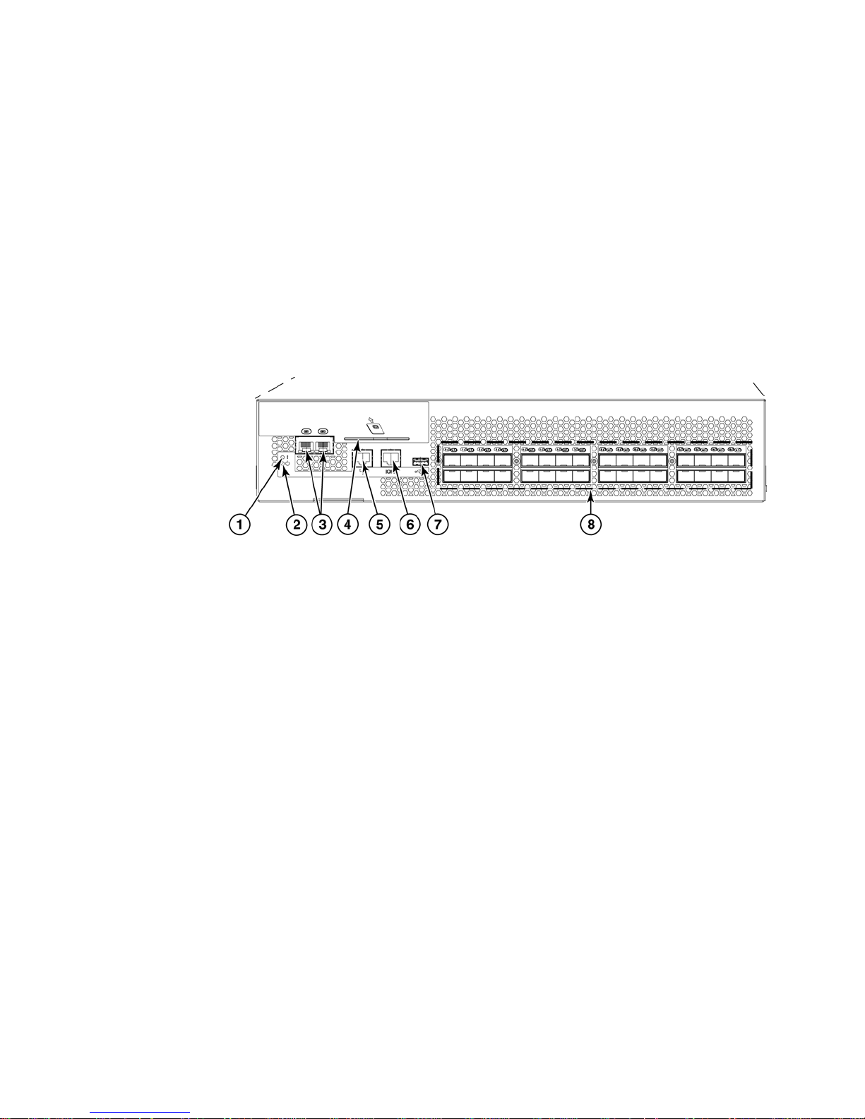
The Brocade encryption switch (Figure 1) is a high performance 32 port auto-sensing 8 Gbps Fibre
Channel switch with data cryptographic (encryption/decryption) and data compression capabilities.
The switch is a network-based solution that secures data-at-rest for heterogeneous tape drives,
disk array LUNs, and virtual tape libraries by encrypting the data, using Advanced Encryption
Standard (AES) 256-bit algorithms. Encryption and decryption engines provide in-line encryption
services with up to 96 Gbps throughput for disk I/O (mix of ciphertext and cleartext traffic) and up
to 48 Gbps throughput for tape I/O (mix of ciphertext and cleartext traffic). Refer to “The FS8-18
blade” on page 5 for information about license requirements for 48 Gbps and 96 Gbps bandwidth.
In addition to its 32 Fibre Channel ports, the switch has one RJ45 Gigabit Ethernet (GE)
management port, two RJ45 GE ports for clustering interconnection and re-key synchronization,
one RJ45 Serial console port, and one USB port for serviceability, error logging, and firmware
upgrades.
1
2
3
4
5
6
7
8
Power LED.
Status LED.
RJ45 gigabit Ethernet ports for clustering and centralized management of multiple encryption
switches through a group leader.
Smart card reader.
RJ45 gigabit Ethernet port for the management interface. This interface is used for the secure
connection to the key vault location and to the Data Center Fabric Manager (DCFM).
RJ45 serial console port.
USB port for firmware upgrades and other support services.
Fibre Channel ports (0-31) - 1, 2, 4, or 8 Gbps auto-sensing F, FL, E, EX, or M ports to connect
host servers, SAN disks, SAN tapes, edge switches, or core switches.
FIGURE 1 Brocade encryption switch
4 Fabric OS Encryption Administrator’s Guide
53-1001864-01
Page 23

The FS8-18 blade
The FS8-18 blade provides the same features and functionality as the encryption switch. The
FS8-18 blade installs on the Brocade DCX and DCX-4S. Four FS8-18 blades may be installed in a
single DCX or DCX-4S.
Performance licensing
Encryption processing power is scalable, and may be increased by purchasing and installing an
encryption performance license. The base unit Brocade Encryption Switch and FS8-18 Encryption
Blade have a standard capacity of 48 Gbps of encryption processing power. Additional encryption
processing power can be added for disk I/O by purchasing and installing a Disk Advanced
Encryption Performance license. When the performance upgrade license is applied, encryption
processing power of up to 96 Gbps is available. Note that when the license is applied to a DCX or
DCX-4S chassis, it applies to all FS8-18 blades installed on that chassis.
Adding a license
The FS8-18 blade
1
The encryption performance licenses are added just like any other Fabric OS feature license. After
the license is added, the encryption switch, DCX, or DCX-4S with encryption blades installed must
be rebooted for the license to take effect. See the Fabric OS Administrator’s Guide for information
about obtaining and adding licenses.
Licensing best practices
Licenses installed on the switches and blades must have identical performance numbers when
used together in high availability (HA) clusters or data encryption key (DEK) clusters.
Fabric OS Encryption Administrator’s Guide 5
53-1001864-01
Page 24

Recommendation for connectivity
1
Recommendation for connectivity
In order to achieve high performance and throughput, the encryption engines perform what is
referred to as “cut-through” encryption. In simple terms this is achieved by encrypting the data in
data frames on a per frame basis. This enables the encryption engine to buffer only a frame,
encrypt it and send the frame out to the target on write I/Os. For read I/Os the reverse is done. This
puts some constraints on the topology and the container configurations to support acceptable
performance for encrypted and decrypted I/O to and from LUNs, and to support acceptable levels
of scale in terms of the number of LUNs and the number of flows. The topology and container
configuration constraint is stated below:
Care must be taken when connecting the encryption engines to the fabric and configuring
crypto-target containers to be sure that the traffic flow between the host initiator and the physical
storage array LUN through the container flows through only one encryption engine that is hosting
the container. This is to avoid crisscrossing of flows to and from virtual entities; that is, from virtual
targets and virtual initiators on two different encryption engines over the same path.
Although there is considerable flexibility in connecting and configuring the containers for
encryption, the following guidelines are the recommended best practices:
• Host and Storage Array ports that are not involved in any encryption flow can be connected to
any Encryption Engines.
• Recommendations for host and target ports with respect to encryption flows are as follows:
- Only ISLs are connected to the Brocade Encryption Switch encryption engine in order to
- Only host ports are connected to the FS8-18 blade encryption engine. and no ISLs are
Usage limitations
There are usage limitations to be aware of when planning an encryption implementation:
• Special redirection zones are created to handle data that is redirected to an encryption switch
or blade. Quality of Service (QoS) cannot be applied to a redirection zone.
• In order for frame redirection to be applied, regular zones for hosts and targets must be
defined in the effective configuration. Hosts and targets must be zoned together by worldwide
port name (WWPN) rather than worldwide node name (WWNN) in configurations where frame
redirection will be used. If hosts or targets are zoned together using worldwide node name,
frame redirection will not occur properly.
• On tapes written in DataFort format, the encryption switch or blade cannot read and decrypt
files with a block size of one MB or greater.
• Th e To p Talker feature is not compatible wi t h redirection z o n e s. The Top Talker featur e s hould
not be enabled when an encryption switch or blade is present in the fabric.
connect it to the fabric. No devices (initiators and targets) are connected to it.
connected to it.
6 Fabric OS Encryption Administrator’s Guide
53-1001864-01
Page 25
Host
Encryption Switch
Cleartext
DEKs
Ciphertext
based on
AES256-GCM
Ciphertext
based on
AES256-XTS
Disk Storage
Tape Storage
Key Management
System
Ciphertext
Cleartext
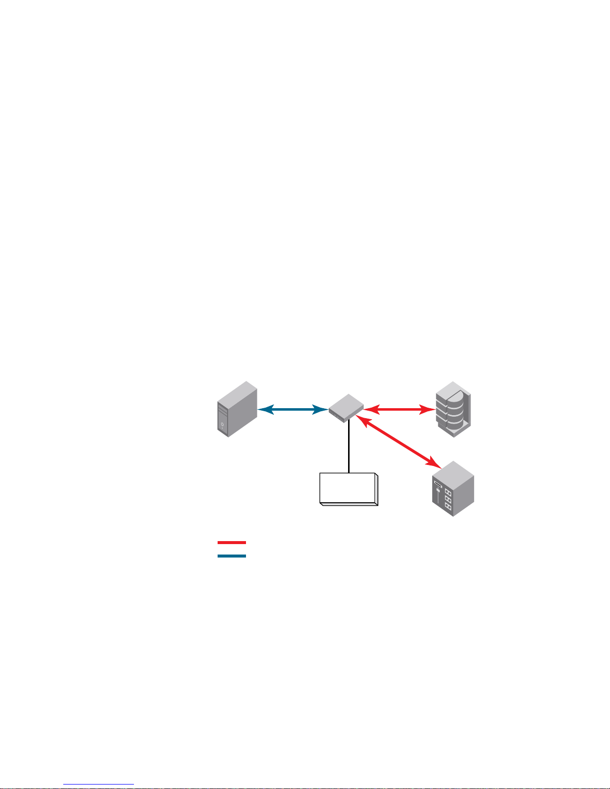
Brocade encryption solution overview
The loss of stored private data, trade secrets, intellectual properties, and other sensitive
information through theft or accidental loss of disk or tape media can have widespread negative
consequences for governments, businesses, and individuals. This threat is countered by an
increasing demand from governments and businesses for solutions that create and enforce
policies and procedures that protect stored data. Encryption is a powerful tool for data protection.
Brocade provides an encryption solution that resides in a Storage Area Network (SAN) fabric. This
location, between computers and storage, is ideal for implementing a solution that works
transparently with heterogeneous servers, disk storage subsystems, and tape libraries. Data
entering the SAN from a server is encrypted before it is written to storage. When stored data is
encrypted, theft or loss of storage media does not pose a security threat.
Figure 2 provides a high level view of the Brocade encryption solution. Cleartext is sent from the
server to the encryption engine, where it is encrypted into ciphertext using one of two encryption
algorithms, one for disk storage targets, and one for tape storage targets. The encrypted data
cannot be read without first being decrypted. The key management system is required for
management of the data encryption keys (DEKs) that are generated by the encryption engine, and
used for encrypting and decrypting the data. The key management system is provided by a third
party vendor.
Brocade encryption solution overview
1
FIGURE 2 Encryption overview
Fabric OS Encryption Administrator’s Guide 7
53-1001864-01
Page 26
Brocade encryption solution overview
Host
Encryption
Switch
Ciphertext
Cleartext
Virtual
Initiator
Lun
X
Virtual
Target
Fabric 1
Target
1
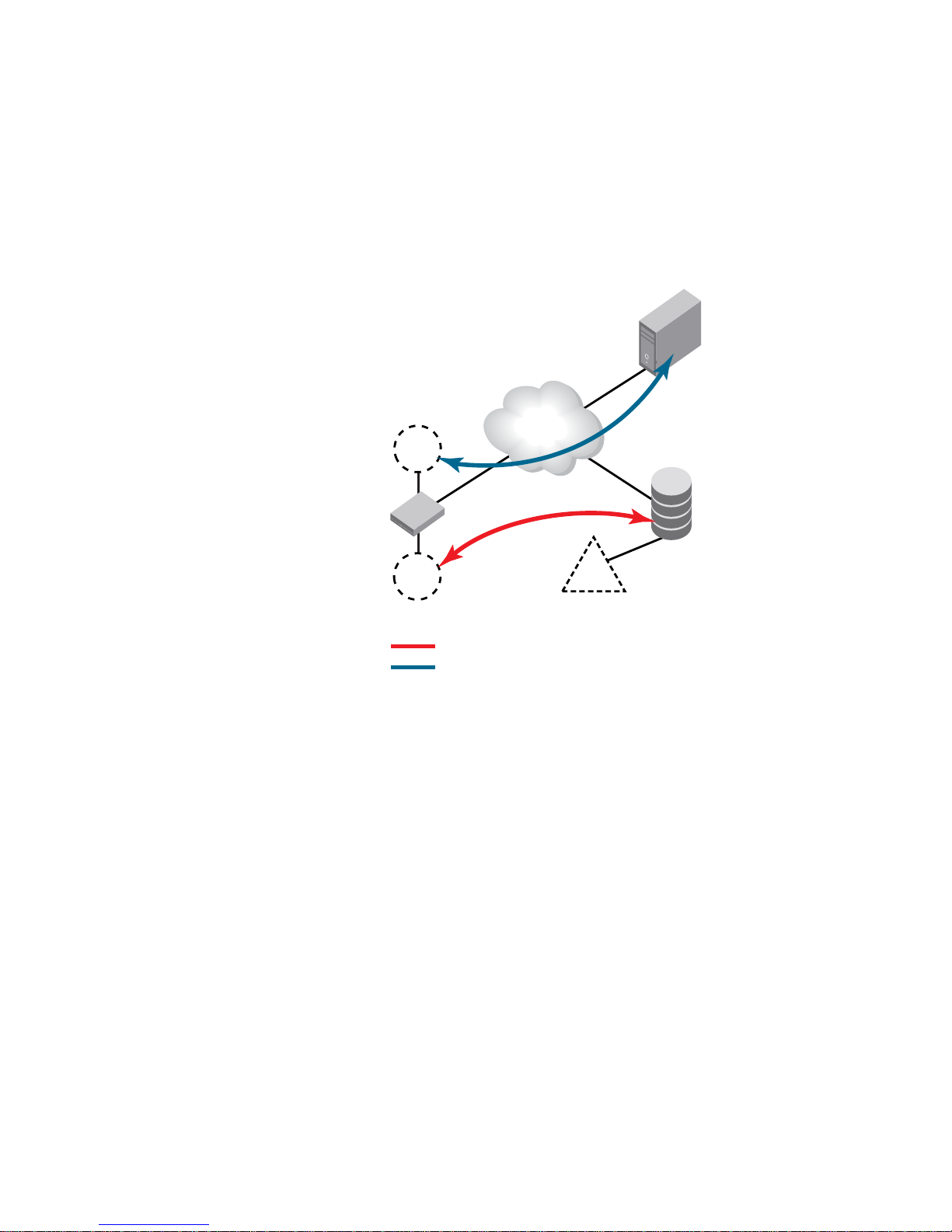
Data flow from server to storage
The Brocade encryption switch can be introduced into a SAN with minimum disruption, with no
need for SAN reconfiguration, and with no need to reconfigure host applications. Frames sent from
a host and a target LUN are redirected to a virtual target associated with the encryption switch. The
encryption switch then acts as a virtual initiator to forward the frames to the target LUN.
FIGURE 3 Frame redirection
8 Fabric OS Encryption Administrator’s Guide
53-1001864-01
Page 27
Node 1
Key Management
System
EE
Node 2
Group Leader
Management Group
EE
Node 3
EE
Node 4
EE
IO Sync LAN
LAN
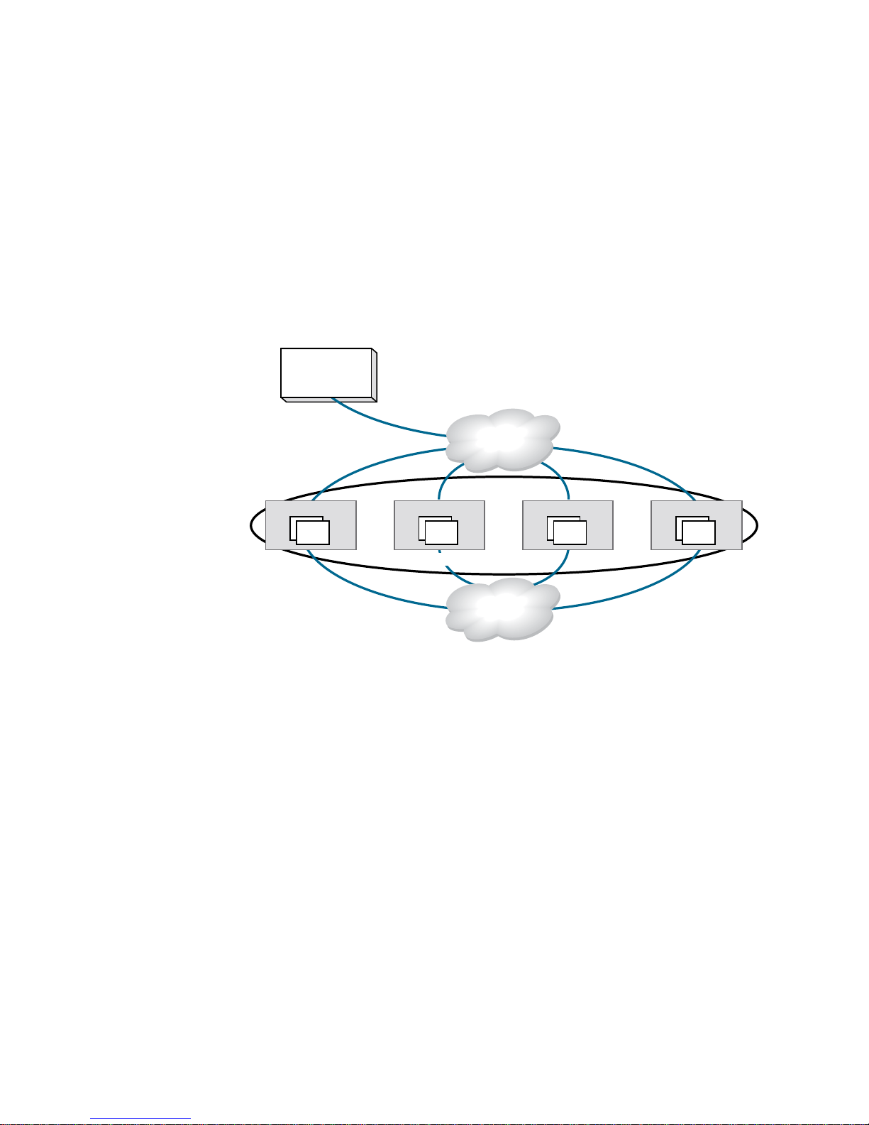
Data encryption key life cycle management
Data encryption key life cycle management
Data encryption keys (DEKs) are generated by the encryption engine. Data is encrypted and
decrypted using the same DEK, so a DEK must be preserved at least long enough to decrypt the
ciphertext that it created. The length of time data is stored before it is retrieved can vary greatly,
and some data may be stored for years or decades before it is accessed. To be sure the data
remains accessible, DEKs may also need to be stored for years or decades. Key management
systems provide life cycle management for all DEKs created by the encryption engine. Key
management systems are provided by third party vendors.
Figure 4 shows the relationship of the LAN connections to the key vault and between encryption
nodes.
1
FIGURE 4 LAN connections to the key vault, and between encryption nodes
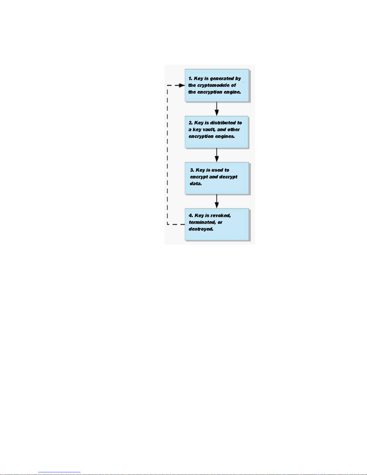
Regardless of the length of the life cycle, there are four stages in the life of a DEK, as shown in
Figure 5. A DEK is created by an encryption engine, distributed, and stored in a key vault. The key is
used to encrypt and decrypt data at least once, and possibly many times. A DEK may be configured
to expire in a certain time frame, or it may become compromised. Under those conditions, it must
be used one more time to decrypt the data, and the resulting cleartext is encrypted with a new key
(re-keyed).
Fabric OS Encryption Administrator’s Guide 9
53-1001864-01
Page 28
Data encryption key life cycle management
1
FIGURE 5 DEK life cycle
10 Fabric OS Encryption Administrator’s Guide
53-1001864-01
Page 29

Key management systems
Key management systems are available from several vendors. This release supports the following
leading key management systems:
• The NetApp LIfetime Key Manager (LKM) version 4.0 or later.
• The RSA Key Manager (RKM) version 2.1.3 or later, available through EMC.
• The HP Secure Key Manager (SKM) version 1.1 or later, available through Hewlett Packard.
• The Thales Encryption Manager for Storage (TEMS).
Master key management
Communications with opaque key vaults are encrypted using a master key that is created by the
encryption engine on the encryption switch. Currently, this includes the key vaults of all supported
key management systems except NetApp LKM.
Master key generation
Key management systems
1
A master key must be generated by the group leader encryption engine. The master key can be
generated once by the group leader, and propagated to the other members of an encryption group.
Master key backup
It is essential to back up the master key immediately after it is generated. The master key may be
backed up to any of the following,
• To a file as an encrypted key.
• To the key management system as an encrypted key record.
• To a set of recovery smart cards. This option is only available if the switch is managed by the
Data Center Fabric Manager (DFCM), and if a card reader is available for attachment to the
DCFM workstation.
The use of smart cards provides the highest level of security. When smart cards are used, the key is
split and written on up to five cards, and the cards may be kept and stored by up to five individuals,
and all are needed to restore the master key.
Fabric OS Encryption Administrator’s Guide 11
53-1001864-01
Page 30

Support for Virtual Fabrics
NOTE
1
Support for Virtual Fabrics
The Brocade encryption switch does not support the logical switch partitioning capability and can
not be partitioned, but the switch can be connected to any Logical Switch partition or Logical Fabric
using an E-Port.
The FS8-18 encryption blades are supported in only in a default switch partition All FS8-18 blades
must be placed in a default switch partition in DCX or DCX-4S. The encryption resource from
default switch partition/fabric can be shared with other logical switch partitions/fabrics or other
fabrics only through external device sharing using FCR or EX_Ports through a base switch/fabric. A
separate port blade must be used in the base switch/fabric for EX_Port connectivity from the
logical switch partition (default switch partition) of FS8-18 blades and host/target fabrics. The
EX_Port can be on any external FCR switch.
Please refer to Fabric OS Administrator’s Guide for more details on how to configure the DCX and
DCX-4S in virtual fabrics environments including configuration of default switch partition and any
other logical switch partitions.
12 Fabric OS Encryption Administrator’s Guide
53-1001864-01
Page 31

Chapter
Encryption configuration using the Management
application
In this chapter
•Encryption Center features . . . . . . . . . . . . . . . . . . . . . . . . . . . . . . . . . . . . . . . 14
•Encryption user privileges . . . . . . . . . . . . . . . . . . . . . . . . . . . . . . . . . . . . . . . . 15
•Smart card usage . . . . . . . . . . . . . . . . . . . . . . . . . . . . . . . . . . . . . . . . . . . . . . 16
•Network connections. . . . . . . . . . . . . . . . . . . . . . . . . . . . . . . . . . . . . . . . . . . . 22
•Configuring blade processor links . . . . . . . . . . . . . . . . . . . . . . . . . . . . . . . . . 22
•Encryption node initialization and certificate generation. . . . . . . . . . . . . . . 23
•Steps for connecting to an SKM appliance . . . . . . . . . . . . . . . . . . . . . . . . . . 24
•Gathering information . . . . . . . . . . . . . . . . . . . . . . . . . . . . . . . . . . . . . . . . . . . 33
•Gathering information . . . . . . . . . . . . . . . . . . . . . . . . . . . . . . . . . . . . . . . . . . . 33
•Creating a new encryption group . . . . . . . . . . . . . . . . . . . . . . . . . . . . . . . . . . 34
•Adding a switch to an encryption group. . . . . . . . . . . . . . . . . . . . . . . . . . . . . 41
•Creating high availability (HA) clusters. . . . . . . . . . . . . . . . . . . . . . . . . . . . . . 46
•Adding encryption targets . . . . . . . . . . . . . . . . . . . . . . . . . . . . . . . . . . . . . . . . 49
•Configuring hosts for encryption targets . . . . . . . . . . . . . . . . . . . . . . . . . . . . 56
•Adding target disk LUNs for encryption . . . . . . . . . . . . . . . . . . . . . . . . . . . . . 57
•Adding Target Tape LUNs for encryption . . . . . . . . . . . . . . . . . . . . . . . . . . . . 59
•Configuring encrypted tape storage in a multi-path environment . . . . . . . . 60
•Master keys . . . . . . . . . . . . . . . . . . . . . . . . . . . . . . . . . . . . . . . . . . . . . . . . . . . 61
•Zeroizing an encryption engine . . . . . . . . . . . . . . . . . . . . . . . . . . . . . . . . . . . 71
2
Fabric OS Encryption Administrator’s Guide 13
53-1001864-01
Page 32

Encryption Center features
2
Encryption Center features
The Encryption Center dialog box (Figure 6) is the single launching point for all encryption-related
configuration in the Management application. It also provides a table that shows the general status
of all encryption-related hardware and functions at a glance.
FIGURE 6 Encryption Center dialog box
Beginning with Fabric OS version 6.4, the Encryption Center is dynamically updated to reflect the
latest changes based on any of the following events:
• Encryption group creation or deletion.
• A change in encryption group status.
• Addition or removal of an encryption group member.
• Addition or removal of an encryption engine.
• A change in encryption engine status.
If you are using the Encryption Center for the first time, please read the following topics before you
begin to perform encryption operations:
• “Encryption user privileges” on page 15 describes the Role-based Access Control privileges
that are specific to encryption.
• “Smart card usage” on page 16 and the topics that follow describe the options available for the
use of Smart Cards for user authentication, system access control, and storing backup copies
of data encryption master keys.
• “Network connections” on page 22 describes the network connections that must be in place to
enable encryption.
• “Configuring blade processor links” on page 22 describes the steps for interconnecting
encryption switches or blades in an encryption group through a dedicated LAN. This must be
done before their encryption engines are enabled. Security parameters and certificates cannot
be exchanged if these links are not configured and active.
• “Encryption node initialization and certificate generation” on page 23 lists the security
parameters and certificates that are generated when an encryption node is initialized.
• “Steps for connecting to an SKM appliance” on page 24 lists the supported key manager
appliances, and lists topics that provide additional detail.
14 Fabric OS Encryption Administrator’s Guide
53-1001864-01
Page 33

Encryption user privileges
In the Management application, resource groups are assigned privileges, roles, and fabrics.
Privileges are not directly assigned to users; users get privileges because they belong to a role in a
resource group. A user can only belong to one resource group at a time.
The Management application provides three pre-configured roles:
• Storage encryption configuration.
• Storage encryption key operations.
• Storage encryption security.
Tab le lists the associated roles and their read/write access to specific operations.
Privilege Read/Write
Encryption user privileges
2
Storage Encryption
Configuration
Storage Encryption Key
Operations
Storage Encryption
Security
Enables the following functions from the Encryption Center dialog box:
• Launch the Configure Encryption dialog.
• View switch, group, or engine properties.
• View the Encryption Group Properties Security tab.
• View encryption targets, hosts, and LUNs.
• View LUN centric view
• View all re-key sessions
• Add/remove paths and edit LUN configuration on LUN centric view
• Rebalance encryption engines.
• Decommission LUNs
• Edit smart card
• Create a new encryption group or add a switch to an existing encryption group.
• Edit group engine properties (except for the Security tab)
• Add targets.
• Select encryption targets and LUNs to be encrypted or edit LUN encryption settings.
• Edit encryption target hosts configuration.
Enables the following functions from the Encryption Center dialog box:
• Launch the Configure Encryption dialog.
• View switch, group, or engine properties,
• View the Encryption Group Properties Security tab.
• View encryption targets, hosts, and LUNs.
• Initiate manual LUN re-keying.
• Enable and disable an encryption engine.
• Zeroize an encryption engine.
• Restore a master key.
• Edit key vault credentials.
Enables the following functions from the Encryption Center dialog box:
• Launch the Configure Encryption dialog.
• View switch, group, or engine properties.
• View encryption targets, hosts, and LUNs.
• Create a master key.
• Backup a master key.
• View and modify settings on the Encryption Group Properties Security tab (quorum size,
authentication cards list and system card requirement).
• Establish link keys for LKM key managers.
Fabric OS Encryption Administrator’s Guide 15
53-1001864-01
Page 34

Smart card usage
2
Smart card usage
Smart Cards are credit card-sized cards that contain a CPU and persistent memory. Smart cards
can be used as security devices. You must have Storage Encryption Security user privileges to
activate, register, and configure smart cards.
Smart cards can be used to do the following:
• Control user access to the Management application security administrator roles.
• Control activation of encryption engines.
• Securely store backup copies of master keys.
Smart card readers provide a plug-and-play interface to read and write to a smart card. The
following smart card readers are supported:
• GemPlus GemPC USB
http://www.gemalto.com/readers/index.html
• SCM MicrosystemsSCR331
http://www.scmmicro.com/security/view_product_en.php?PID=2
See the following procedures for instructions about how to manage smart cards:
• “Registering authentication cards from a card reader” on page 16
• “Registering system cards from a card reader” on page 19
• “Tracking smart cards” on page 20
• “Saving a master key to a smart card set” on page 65
• “Restoring a master key from a smart card set” on page 69
Registering authentication cards from a card reader
When authentication cards are used, one or more authentication cards must be read by a card
reader attached to a Management application PC to enable certain security sensitive operations.
These include the following:
• Master key generation, backup, and restore operations.
• Replacement of authentication card certificates.
• Enabling and disabling the use of system cards.
• Changing the quorum size for authentication cards.
• Establishing a trusted link with the NetApp LKM key manager.
• Decommissioning LUNs.
To register an authentication card or a set of authentication cards from a card reader, have the
cards physically available. Authentication cards can be registered during encryption group or
member configuration when running the configuration wizard, or they can be registered using the
following procedure.
1. Select Configure > Encryption from the menu bar.
The Encryption Center dialog box displays.
2. Select an encryption group, and select Security Settings.
16 Fabric OS Encryption Administrator’s Guide
53-1001864-01
Page 35

Smart card usage
NOTE
3. Select the Quorum Size.
The quorum size is the minimum number of cards necessary to enable the card holders to
perform the security sensitive operations listed above. The maximum quorum size is five cards.
The actual number of authentication cards registered is always more than the quorum size, so
if you set the quorum size to five, for example, you will need to register at least six cards in the
subsequent steps.
Ignore the System Cards setting. Refer to “Tracking smart cards” on page 20 for information on
its usage.
4. Click Next.
The Register Authentication Cards dialog is displayed. This dialog include a table that shows all
registered authentication cards.
5. Select Register from Card Reader to register a new card.
The Add Authentication Card dialog box is displayed.
6. Insert a smart card into the card reader. Be sure to wait for the card serial number to appear,
and then enter card assignment information, as directed.
2
7. C l ic k OK.
8. Wait for the confirmation dialog box indicating initialization is done, and click OK.
The card is added to the Registered Authentication Cards table on the Authentication Cards
dialog box.
9. Repeat steps 7 through 10 until you have registered all the cards, and they all display in the
Registered Authentication Cards table on the Authentication Cards dialog box. Remember that
you need to register the number selected as the quorum size plus one.
Registering authentication cards from the database
Smart cards that are already in the Management program’s database can be registered as
authentication cards.
1. From the Register Authentication Cards dialog box, select Register from Archive.
The Authentication Cards dialog box displays, showing a list of smart cards in the database.
2. Select the card from the table, and click OK.
3. Wait for the confirmation dialog box indicating initialization is done, and click OK.
The card is added to the Registered Authentication Cards table.
Fabric OS Encryption Administrator’s Guide 17
53-1001864-01
Page 36

Smart card usage
2
De-registering an authentication card
Authentication cards can be removed from the database and the switch by de-registering them.
Use the following procedure to de-register an authentication card.
1. Select the authentication card on the Authentication Card table.
2. Click Deregister.
3. A confirmation dialog box is displayed. Click OK to confirm de-registration.
The Encryption Group dialog box displays.
4. Click OK on the Encryption Group dialog box.
The card is de-registered from the group.
Using authentication cards
When a quorum of authentication cards are registered for use, an Authenticate dialog box is
displayed to grant access to the following:
• The Encryption Group Properties dialog box Link Keys tab.
• The Encryption Group Properties dialog box Security tab, which provides access to the
following:
- Master Key Actions, which includes Backup Master Key, Restore Master Key, and Create
Master Key.
- The System Cards radio buttons used to specify whether or not a system card is Required
or Not Required.
- The Authentication Card Quorum Size selector.
- The Register from Card Reader and Register From Archive buttons.
• The Master Key Backup dialog box.
• The Master Key Restore dialog box.
• The Decommission LUNs dialog box.
To authenticate using a quorum of authentication cards, do the following:
1. When the Authenticate dialog box is displayed, gather the number of cards needed, as directed
by instructions on the dialog box. The currently registered cards and the assigned owners are
listed in the table near the bottom of the dialog box.
2. Insert a card, and wait for the ID to appear in the Card ID field.
3. Enter the assigned password.
4. Click Authenticate.
5. Wait for the confirmation dialog box, and click OK.
6. Repeat steps two through five for each card until the quorum is reached.
7. C l ic k OK.
18 Fabric OS Encryption Administrator’s Guide
53-1001864-01
Page 37

Smart card usage
2
Enabling or disabling the system card requirement
If you want to use a system card to control activation of an encryption engine on a switch, you must
enable the system card requirement. You can use the following procedure to enable or disable the
system card requirement.
1. From the Encryption Center select an encryption group, and select the Security menu.
The Select Security Settings dialog is displayed.
2. Set System Cards to Required to require the use a system card to control activation of an
encryption engine. If System Cards is set to Not Required, the encryption engine activates
without the need to read a system card first.
3. Click OK.
Registering system cards from a card reader
System cards are smart cards that can be used to control activation of encryption engines.
Encryption switches and blades have a card reader that enables the use of a system card. System
cards discourage theft of encryption switches or blades by requiring the use of a system card at the
switch or blade to enable the encryption engine. When the switch or blade is powered off, the
encryption engine will not work without first inserting a system card into its card reader. If someone
removes a switch or blade with the intent of accessing the encryption engine, it will function as an
ordinary FC switch or blade when it is powered up, but use of the encryption engine is denied.
To register a system card from a card reader, a smart card must physically available. System cards
can be registered during encryption group creation or member configuration when running the
configuration wizard, or they can be registered using the following procedure.
1. Select Configure > Encryption from the menu bar.
The Encryption Center dialog box displays.
2. Select the switch from the Encryption Devices table, and select Switch > System Cards from
the menu task bar, or right-click the switch or and select System Card.
The Register System Card dialog box is displayed.
3. Insert a smart card into the card reader. Be sure to wait for the card serial number to appear,
and then enter card assignment information, as directed.
4. Click OK.
5. Wait for the confirmation dialog box indicating initialization is done, and click OK.
The card is added to the Registered System Cards table on the System Cards dialog box.
6. Store the card in a secure location, not in the proximity of the switch or blade.
Fabric OS Encryption Administrator’s Guide 19
53-1001864-01
Page 38

Smart card usage
NOTE
2
De-registering a system card
System cards can be removed from the database by de-registering them. Use the following
procedure to de-register a system card.
1. From the Register System Card dialog box, select the system card you want to de-register.
2. Click Deregister.
3. A confirmation dialog box is displayed. Click OK to confirm de-registration.
The card is removed to the Registered System Cards table.
Tracking smart cards
Use the Smart Card Tracking dialog box to track smart card details.
From the Encryption Center, select Smart Card > Smart Card Tracking.
The Smart Card Tracking dialog box displays (Figure 7).
FIGURE 7 Smart Card asset tracking dialog box
Clicking the Delete button removes a selected smart card from the Management application
database. Deleting smart cards from the Management application database keeps the Smart
Cards table at a manageable size, but does not invalidate the smart card. The smart card can still
be used. You must de-register a smart card to invalidate its use.
The Delete operation applies only to recovery cards.
Clicking the Save As button saves the entire list of smart cards to a file. The available formats are
comma-separated values (.csv) and HTML files (.html).
20 Fabric OS Encryption Administrator’s Guide
53-1001864-01
Page 39

Editing smart cards
Use the Edit Smart Card dialog box to edit smart card details.
1. From the Encryption Center, select Smart Card > Edit Smart Card.
The Edit Smart Card dialog box displays(Figure 8).
Smart card usage
2
FIGURE 8 Edit Smart Card dialog box
2. Insert the smart card into the card reader.
3. After the card’s ID is displayed in the Card ID field, enter the Card Password and click Login.
4. Edit the card assignment user information as needed.
5. Click OK.
Fabric OS Encryption Administrator’s Guide 21
53-1001864-01
Page 40

Network connections
2
Network connections
Before you use the encryption setup wizard for the first time, you must have the following required
network connections:
• The management ports on all encryption switches and 384-port Backbone Chassis CPs that
have encryption blades installed must have a LAN connection to the SAN management
program, and must be available for discovery.
• A supported key management appliance must be connected on the same LAN as the
management port of the encryption switches, 384-port Backbone Chassis CPs, and the SAN
Management program.
• In some cases, you may want to have an external host available on the LAN to facilitate
certificate exchange between encryption nodes and the key management appliance. You may
use the SAN management program host computer rather than an external host.
• All switches in the planned encryption group must be interconnected on a private LAN. This
LAN is used to exchange security parameters and certificates, and to synchronize encryption
engine operations. Refer to “Configuring blade processor links” on page 22 for details.
Configuring blade processor links
Each encryption switch or blade has two GbE ports labeled Ge0 and Ge1. The Ge0 and Ge1 ports
are Ethernet ports that connect encryption switches and blades to other encryption switches and
blades. Both ports of each encryption switch or blade must be connected to the same IP network,
and the same subnet. Static IP addresses should be assigned. VLANs should not be used, and
DHCP should not be used. These two ports are bonded together as a single virtual network
interface to provide link layer redundancy.
All encryption switches or blades in an encryption group must be interconnected by these links
through a dedicated LAN before their encryption engines are enabled. Security parameters and
certificates cannot be exchanged if these links are not configured and active.
Take the following steps to configure blade processor links.
1. Select Configure > Encryption from the menu bar.
The Encryption Center dialog box displays.
2. Right click on the encryption engine, and select Blade Processor Link.
The Blade Processor Link dialog box displays.
3. Enter the link IP address and mask, and the gateway IP address.
4. Click OK.
The Blade Processor Link dialog box may also be launched from the following locations:
- Select Group > HA Clusters and select the Configure Blade Processor Link button.
- Select a Group, Switch or Encryption Engine, select Targets > LUN and select the Configure
Blade Processor Link button.
22 Fabric OS Encryption Administrator’s Guide
53-1001864-01
Page 41

Encryption node initialization and certificate generation
Encryption node initialization and certificate generation
When an encryption node is initialized, the following security parameters and certificates are
generated:
• FIPS crypto officer
• FIPS user
• Node CP certificate
• A self-signed Key authentication center (KAC) certificate
• A Key authentication center (KAC) signing request (CSR)
From the standpoint of external SAN management application operations, the FIPS crypto officer,
FIPS user, and node CP certificates are transparent to users. The KAC certificates are required for
operations with key managers. In most cases, KAC certificate signing requests must be sent to a
Certificate Authority (CA) for signing to provide authentication before the certificate can be used. In
all cases, signed KACs must be present on each switch.
Encryption nodes are initialized by the Configure Switch Encryption wizard when you confirm a
configuration.
Encryption nodes may also be initialized from the Encryption Center.
2
1. From the Encryption Center, select Switch > Init Node.
The following warning displays.
2. Select Yes to initialize the node.
Fabric OS Encryption Administrator’s Guide 23
53-1001864-01
Page 42

Steps for connecting to an SKM appliance
2
Steps for connecting to an SKM appliance
The SKM management web console can be accessed from any web browser with Internet access to
the SKM appliance. The URL for the appliance is as follows:
https://<appliance hostname>:<appliance port number>
Where:
- <appliance hostname> is the hostname or IP address when installing the SKM appliance.
- <appliance port number> is 9443 by default. If a different port number was specified
when installing the SKM appliance, use that port number.
The following configuration steps are performed from the SKM management web console and from
the Management application.
• Configure a Brocade group on SKM.
• Register the Brocade group user name and password on the encryption node.
• Set up a local Certificate Signing Authority (CA) on SKM.
• Download the CA certificate.
• Create and install an SKM server certificate.
• Enable an SSL connection.
• Configure a cluster of SKM appliances for high availability.
• Export and sign the encryption node certificate signing requests.
• Import the signed certificates into the encryption node.
These steps are described in more detail in the following sections.
24 Fabric OS Encryption Administrator’s Guide
53-1001864-01
Page 43

Steps for connecting to an SKM appliance
NOTE
Configuring a Brocade group on SKM
A Brocade group is configured on SKM for all keys created by Brocade encryption switches and
blades. This needs to be done only once for each key vault.
1. Login to the SKM management web console using the admin password.
2. Select the Security tab.
3. Select Local Users & Groups under Users and Groups.
The User & Group Configuration page displays.
4. Select Add under Local Users.
5. Create a Brocade user name and password.
6. Select the User Administration Permission and Change Password Permission check boxes.
7. S e le c t Save to save this user data.
8. Select Add under Local Groups.
9. Add a Brocade group under Group.
10. Select Save.
2
11. Select the new Brocade group name, and then select Properties.
Local Group Properties and a User List are displayed.
12. In the User List section, select or type the Brocade user name under Username.
13. Select Save.
The Brocade user name and password are now configured on SKM.
Fabric OS version 6.2.0 uses brcduser1 as a standard user name when creating a Brocade group
on SKM. If you downgrade to version 6.2.0, the user name is overwritten to brcduser1, and the
Brocade group user name must be changed to brcduser1.
Fabric OS Encryption Administrator’s Guide 25
53-1001864-01
Page 44

Steps for connecting to an SKM appliance
2
Registering the SKM Brocade group user name and password
The Brocade group user name and password you created when configuring a Brocade group on
SKM must also be registered on each Brocade encryption node.
1. From the Encryption Center, select Key Vault Credentials.
2. Enter the Brocade group user name and password.
Keep the following rules in mind when registering the Brocade user name and password:
- The user name and password must match the user name and password specified for the
Brocade group.
- The same user name and password must be configured on all nodes in an encryption
group. This is not enforced or validated by the encryption group members, so care must be
taken when configuring the user name and password to ensure they are the same on each
node.
- Different user names and passwords can never be used within the same encryption group,
but each encryption group may have its own user name and password.
- If you change the user name and password, the keys created by the previous user become
inaccessible. The Brocade group user name and password must also be changed to the
same values on SKM to make the keys accessible.
- When storage is moved from one encryption group to another, and the new encryption
group uses different user name and password, the Brocade group user name and
password must also be changed to the same values on SKM to make the keys accessible.
3. Repeat the procedure for each node.
26 Fabric OS Encryption Administrator’s Guide
53-1001864-01
Page 45

Steps for connecting to an SKM appliance
2
Setting up the local Certificate Authority (CA) on SKM
To create and install a local CA, perform the following steps:
1. Login to the SKM management web console using the admin password.
2. Select the Security tab.
3. Under Certificates & CAs, click Local CAs.
4. Enter information required by the Create Local Certificate Authority section of the window to
create your local CA.
- Enter a Certificate Authority Name and Common Name. These may be the same value..
- Enter your organizational information.
- Enter the Email Address to receive messages for the Security Officer.
- Enter the Key Size. HP recommends using 2048 for maximum security.
- Select Self-signed Root CA.
- Enter the CA Certification Duration and Maximum User Certificate Duration. These values
determine when the certificate must be renewed and should be set inaccordance with
your company's security policies. The default value for both is 3650 days or 10 years.
5. Click Create.
The new local CA displays under Local Certificate Authority List (Figure 9).
FIGURE 9 Creating an HP SKM Local CA
5. Under Certificates & CAs, select Trusted CA Lists to display the Trusted Certificate Authority List
Profiles.
6. Click on Default under Profile Name.
Fabric OS Encryption Administrator’s Guide 27
53-1001864-01
Page 46

Steps for connecting to an SKM appliance
2
7. In th e Trusted Certificate Authority List, click Edit.
8. From the list of Available CAs in the right panel, select the CA you just created.
Repeat these steps any time another local CA is needed.
Downloading the local CA certificate from SKM
The local CA certificate you created using the procedure for “Setting up the local Certificate
Authority (CA) on SKM” on page 27 must be saved to your local system. Later, this certificate must
be imported onto the Brocade encryption group leader nodes.
1. From the Security tab, select Local CAs under Certificates and CAs.
2. Select the CA certificate you created.
3. Click Download, and save the certificate file on your local system.
4. Rename the downloaded file, changing the .cert extension to a .pem extension.
Creating and installing the SKM server certificate
To create the SKM server certificate, perform the following steps:
1. Click the Security tab.
2. Under Certificates and CAs, select Certificates.
3. Enter the required information under Create Certificate Request.
- Enter a Certificate Name and Common Name. The same name may be used for both.
- Enter your organizational information.
- Enter the E-mail Address where you want messages to the Security Officer to go.
- Enter the Key Size. HP recommends using the default value: 1024.
4. Click Create Certificate Request.
Successful completion is indicated when the new entry for the server certificate appears on
the Certificate List with a Certificate Status of Request Pending.
5. Select the newly created server certificate from the Certificate List.
6. Select Properties.
The pending request displays under Certificate Request Information.
7. Copy the certificate data from -----BEGIN CERTIFICATE REQUEST----- to -----END CERTIFICATE
REQUEST--––– lines. Be careful to exclude extra carriage returns or spaces after the data.
8. Under Certificates & CAs, select Local CAs.
The Certificate and CA Configuration page is displayed.
9. From the CA Name column, select the name of the local CA you just created in “Setting up the
local Certificate Authority (CA) on SKM” on page 27.
10. Click Sign Request.
28 Fabric OS Encryption Administrator’s Guide
53-1001864-01
Page 47

Steps for connecting to an SKM appliance
11. Enter the required data in the Sign Certificate Request section of the window.
2
- Select the CA name from the Sign with Certificate Authority drop down box.
- Select Server as the Certificate Purpose.
- Enter the number of days before the certificate must be renewed based on your site's
security policies. The default value is 3649 or 10 years.
12. Paste the copied certificate request data into the Certificate Request box.
13. Click Sign Request.
The signed certificate request data displays under Sign Certificate Request.
14. Click Download to download the signed certificate to your local system.
15. Copy the signed certificate data, from -----BEGIN to END…----- lines. Be careful to exclude extra
carriage returns or spaces after the data.
16. From the Security tab select Certificates under Certificates & CAs.
17. Select the server certificate name you just created from the certificate list, and select
Properties.
The Certificate Request Information window displays.
18. Click Install Certificate.
The Certificate Installation window displays.
19. Paste the signed certificate data you copied under Certificate Response and click Save.
The status of the server certificate should change from Request Pending to Active.
Enabling SSL on the Key Management System (KMS) Server
The KMS Server provides the interface to the client. Secure Sockets Layer (SSL) must be enabled
on the KMS Server before this interface will operate. After SSL is enabled on the first appliance it
will be automatically enabled on the other cluster members.
To configure and enable SSL, perform the following steps:
1. Select the Device tab.
2. In the Device Configuration menu, click KMS Server to display the Key Management Services
Configuration window.
3. In the KMS Server Settings section of the window, click Edit. The following warning may display.
4. Configure the KMS Server Settings. Ensure that the port and connection timeout settings are
9000 and 3600, respectively. For Server Certificate, select the name of the certificate you
created in “Creating and installing the SKM server certificate” on page 28.
5. Click Save.
Fabric OS Encryption Administrator’s Guide 29
53-1001864-01
Page 48

Steps for connecting to an SKM appliance
2
Creating an SKM High Availability cluster
The HP SKM key vault supports clustering of HP SKM appliances for high availability. If two SKM
key vaults are configured, they must be clustered. If only a single SKM appliance is configured, it
may be clustered for backup purposes, but the backup appliance will not be directly used by the
switch. The procedures in this section will establish a cluster configuration on one SKM appliance
and then transfer that configuration to the remaining appliances.
• Create the cluster on one SKM appliance that is to be a member of the cluster.
• Copy the local CA certificate from the first SKM appliance or an existing cluster member.
• Paste the local CA certificate it into the management console for each of the SKM appliances
added to the cluster.
To create a cluster, perform the following steps on one of the HP SKM appliances that is to be a
member of the cluster.
1. From the SKM management console, click the Device tab.
2. In the Device Configuration menu, click Cluster.
The Create Cluster section displays.
3. Select and note the Local IP address. You will need this address when you add an appliance to
the cluster.
4. For Local Port, use the default value of 9001 unless you are explicitly directed to use a
different value for your site.
5. Type the cluster password in the Create Cluster section of the main window to create the new
cluster.
6. Click the Create button.
7. In th e Cluster Settings section of the window, click Download Cluster Key and save the key to a
convenient location, such as your computer's desktop. The cluster key is a text file and is only
required temporarily. It may be deleted from your computer's desktop after all SKM appliances
have been added to the cluster.
Copying the local CA certificate for a clustered SKM appliance
Before adding an SKM appliance to a cluster, you must obtain the local CA certificate from the
original SKM or from an SKM that is already in the cluster.
1. Select the Security tab.
2. Select Local CAs under Certificates & CAs.
3. Select the name of the local CA from the Local Certificate Authority list.
The CA Certificate Information is displayed.
4. Copy the certificate request, beginning with
with
---END CERTIFICATE REQUEST---. Be careful not to include any extra characters.
---BEGIN CERTIFICATE REQUEST--- and ending
30 Fabric OS Encryption Administrator’s Guide
53-1001864-01
Page 49

Steps for connecting to an SKM appliance
2
Adding SKM appliances to the cluster
If you are adding an appliance to an existing cluster, select the Cluster Settings section of the
window, click Download Cluster Key and save the key to a convenient location, such as your
computer's desktop.
To add SKM appliances to the cluster you are creating, you will need the original cluster member’s
local IP address, local port number, and the location of the cluster key you downloaded, as
specified in “Creating an SKM High Availability cluster” on page 30.
Perform the following steps on each SKM appliance you want to add to the cluster.
1. Open a new browser window, keeping the browser window from Copying the Local CA
certificate open.
2. In the new browser window, log into the management console of the SKM appliance that is
being added to the cluster and click the Security tab.
3. In the Certificates & CAs menu, click Known CAs.
Enter information required in the Install CA Certificate section near the bottom of the page.
- Typ e t h e Certificate Name of the certificate being transferred from the first cluster
member.
- Paste the copied certificate data into the Certificate box.
4. Click Install.
5. In the Certificates & CA menu, click Trusted CA Lists.
6. Click on the Default Profile Name.
7. C l ic k Edit.
8. Select the name of the CA from the list of Available CAs in the right panel.
9. Click Add.
10. Click Save.
11. Select the Device tab.
12. In the Device Configuration menu, click on Cluster.
13. Click on Join Cluster. In the Join Cluster section of the window, leave Local IP and Local Port set
to their defaults.
14. Type the original cluster member’s local IP address into Cluster Member IP.
15. Type the original cluster member’s local Port into Cluster Member Port.
16. Click Browse and select the Cluster Key File you saved.
17. Type the cluster password into Cluster Password.
18. Click Join.
19. After adding all members to the cluster, delete the cluster key file from the desktop.
20. Create and install an SKM server certificate. Refer to “Creating and installing the SKM server
certificate” on page 28 for a description of this procedure.
Fabric OS Encryption Administrator’s Guide 31
53-1001864-01
Page 50

Steps for connecting to an SKM appliance
2
Signing the Brocade encryption node KAC certificates
The KAC certificate signing request generated when the encryption node is initialized must be
exported for each encryption node and signed by the Brocade local CA on SKM. The signed
certificate must then be imported back into the encryption node.
1. From the Encryption Center, select Switch > Export Certificate.
The Export Switch Certificate dialog box displays.
2. Select Public Key Certificate Request (CSR) and click OK.
A dialog box displays that allows you to save the CSR to your client PC.
Alternatively, you may select Switch > Properties, and click the Export button beside the Public
Key Certificate Request, or copy the CSR for pasting into the Certificate Request Copy area on
the SKM Sign Certificate Request page.
3. Launch the SKM administration console in a web browser and log in.
4. Select the Security tab.
5. Select Local CAs under Certificates & CAs.
The Certificate and CA Configuration page displays.
6. Under Local Certificate Authority List, select the Brocade CA name.
7. S e le c t Sign Request.
The Sign Certificate Request page is displayed.
8. Select Sign with Certificate Authority using the Brocade CA name with the maximum of 3649
days option.
9. Select Client as Certificate Purpose.
10. Allow Certificate Duration to default to 3649.
11. Paste the file contents that you copied in step 3 in the Certificate Request Copy area.
12. Select Sign Request.
Upon success, you are presented with the option of downloading the signed certificate.
13. Download the signed certificate to your local system as signed_kac_skm_cert.pem.
This file is then ready to be imported to the encryption switch or blade.
Importing a signed KAC certificate into a switch
After a KAC CSR has been submitted and signed by a CA, the signed certificate must be imported
into the switch.
1. From the Encryption Center, select Switch > Import Certificate.
The Import Signed Certificate dialog box displays.
2. Browse to the location where the signed certificate is stored.
3. Click OK.
The signed certificate is stored on the switch.
32 Fabric OS Encryption Administrator’s Guide
53-1001864-01
Page 51

Gathering information
Before you use the encryption setup wizard for the first time, you should also have a detailed
configuration plan in place and available for reference. The encryption setup wizard assumes the
following:
• You have a plan in place to organize encryption devices into encryption groups.
• If you want redundancy and high availability in your implementation you have a plan to create
high availability (HA) clusters of two encryption switches or blades to provide failover support.
• All switches in the planned encryption group are interconnected on an I/O synch LAN.
• The management ports on all encryption switches and 384-port Backbone Chassis CPs that
have encryption blades installed have a LAN connection to the SAN management program, and
are available for discovery.
• A supported key management appliance is connected on the same LAN as the encryption
switches, 384-port Backbone Chassis CPs, and the SAN Management program.
• An external host is available on the LAN to facilitate certificate exchange.
• Switch KAC certificates have been signed by a Certificate Authority (CA), and stored in a known
location.
• Key management system (key vault) certificates have been obtained and stored in a known
location.
Gathering information
2
Fabric OS Encryption Administrator’s Guide 33
53-1001864-01
Page 52

Creating a new encryption group
NOTE
2
Creating a new encryption group
The following steps describe how to start and run the encryption setup wizard, and then create a
new encryption group.
When a new encryption group is created, any existing tape pools in the switch are removed.
1. Select Configure > Encryption from the menu bar.
The Encryption Center dialog box displays.
FIGURE 10 Encryption Center - No Group Defined dialog box
2. Select a switch from the <NO GROUP DEFINED> encryption group. The switch must not be in
an encryption group already.
3. Select a switch and select Encryption > Create/Add to Group, from the menu bar, or right-click
the switch and select Create/Add to Group.
The Configure Switch Encryption welcome panel displays.
34 Fabric OS Encryption Administrator’s Guide
53-1001864-01
Page 53

Creating a new encryption group
NOTE
4. Click Next.
Create a new encryption Group is pre-selected. This is the correct selection for creating a new
group.
2
FIGURE 11 Designate Switch Membership dialog box
5. Enter an Encryption Group Name for the encryption group (the maximum length of the group
name is 15 characters; letters, digits, and underscores are allowed) and select the Automatic
failback mode.
If the name you enter for the encryption group already exists, a pop-up warning message
displays. Although unique group names avoid confusion while managing multiple groups, you
are not prevented from using duplicate group names. Click Yes to use the same name for the
new encryption group, or click No to enter a new, unique name.
6. Click Next.
The Select Key Vault dialog box displays (Figure 12).
Fabric OS Encryption Administrator’s Guide 35
53-1001864-01
Page 54

Creating a new encryption group
2
FIGURE 12 Select Key Vault dialog box
7. Select SKM as the Key Vault Type.
36 Fabric OS Encryption Administrator’s Guide
53-1001864-01
Page 55

Creating a new encryption group
When you select SKM, the options are as shown in Figure 13.
a. Enter the IP address or host name for the primary key vault.
b. Enter the name of the file that holds the primary key vault’s public key certificate or
browse to the location by clicking the Browse button.
c. Enter the user name and password you established for the Brocade user group.
d. If you are using a backup key vault, also enter the IP address or host name, and the name
of the file holding the backup key vault’s public key certificate in the fields provided. The
same user name and password used for the primary key vault are automatically applied to
the backup key vault.
2
FIGURE 13 SKM Key Vault Options
e. Click Next.
The Specify Public Key Certificate File Name dialog box displays (Figure 14).
Fabric OS Encryption Administrator’s Guide 37
53-1001864-01
Page 56

Creating a new encryption group
2
FIGURE 14 Specify Public Key Certificate filename dialog box
8. Specify the name of the file where you want to store the public key certificate that is used to
authenticate connections to the key vault, and click Next.
The certificate stored in this file is the switch’s public key certificate. You will need to know this
path and file name to install the switch’s public key certificate on the key management
appliance.
9. Click Next.
The Specify Master Key File Name panel displays (Figure 15).
FIGURE 15 Specify Master Key File Name dialog box
38 Fabric OS Encryption Administrator’s Guide
53-1001864-01
Page 57

Creating a new encryption group
10. Enter a file name, or browse to the desired location.
11. Enter the passphrase, which is required for restoring the master key. The passphrase can be
between eight and 40 characters, and any character is allowed.
12. Re-type the passphrase for verification.
13. Click Next.
The Confirm Configuration panel displays the encryption group name and switch public key
certificate file name you specified, shown in Figure 16.
2
FIGURE 16 Confirm Configuration dialog box
14. Click Next to confirm the displayed information.
The Configuration Status displays, as shown in Figure 17. The configuration status steps vary
slightly depending on the key vault type.
• A progress indicator shows that a configuration step is in progress. A green check mark
indicates successful completion of all steps for that Configuration Item. A red stop sign
indicates a failed step.
• All Configuration Items have green check marks if the configuration is successful. A
message displays below the table, indicating that the encryption switch was added to the
group you named, and the public key certificate is stored in the location you specified.
Fabric OS Encryption Administrator’s Guide 39
53-1001864-01
Page 58

Creating a new encryption group
2
FIGURE 17 Configuration Status dialog box
The Management application sends API commands to verify the switch configuration. The CLI
commands are detailed in the Fabric OS Encryption Administrator’s Guide, “Key vault
configuration.”
• Initialize the switch
If the switch is not already in the initiated state, the Management application performs the
cryptocfg --initnode command.
• Create encryption group on the switch
The Management application creates a new group using the
command, and sets the key vault type using the
cryptocfg --set -keyvault command.
cryptocfg --create -encgroup
• Register key vault(s)
The Management application registers the key vault using the cryptocfg --reg keyvault
command.
• Enable the encryption engines
The Management application initializes an encryption switch using the
[<slotnumber>]
and cryptocfg --regEE [<slotnumber>] commands.
cryptocfg --initEE
• Create a new master key
The Management application checks for a new master key. New master keys are generated
from the Encryption Group Properties dialog box, Security tab. See “Creating a new master key”
on page 70 for more information.
40 Fabric OS Encryption Administrator’s Guide
53-1001864-01
Page 59

• Save the switch’s public key certificate to a file
The Management application saves the KAC certificate into the specified file.
• Back up the master key to a file
The Management application saves the master key into the specified file.
15. Click Next.
The Read Instructions dialog box displays instructions for installing public key certificates for
the encryption switch. These instructions are specific to the key vault type. Copy or print these
instructions.
16. Click Finish to exit the Configure Switch Encryption wizard.
At this point, a Next Steps dialog box is displayed, with brief instructions that are specific to
certificate exchanges between the switch and key manager you are using.
Adding a switch to an encryption group
The setup wizard allows you to either create a new encryption group, or add an encryption switch to
an existing encryption group. Use the following procedure to add a switch to an encryption group.
Adding a switch to an encryption group
2
1. Select Configure > Encryption from the menu bar.
The Encryption Center dialog box displays.
2. Select the switch to be to be added to the group. The switch must not already be in an
encryption group.
3. Select Switch > Create/Add to Group, or right-click the switch and select Create/Add to Group.
The Configure Switch Encryption welcome panel displays.
4. Click Next.
The Designate Switch Membership panel displays.
Fabric OS Encryption Administrator’s Guide 41
53-1001864-01
Page 60

Adding a switch to an encryption group
2
FIGURE 18 Add switch to an encryption group - Designate Switch Membership dialog box
a. Select Add this switch to an existing encryption group.
b. Click Next.
The Add Switch to Existing Encryption Group dialog box displays.
FIGURE 19 Add Switch to Existing Encryption Group dialog box
5. Select the group to which you want to add the switch, and click Next.
The Specify Public Key Certificate Filename panel displays.
42 Fabric OS Encryption Administrator’s Guide
53-1001864-01
Page 61

Adding a switch to an encryption group
2
FIGURE 20 Add switch to an encryption group - Specify Public Key Certificate filename dialog box
6. Specify the name of the file where you want to store the public key certificate that is used to
authenticate connections to the key vault, and click Next.
The Confirm Configuration panel displays the encryption group name and switch public key
certificate file name you specified.
FIGURE 21 Add switch to an encryption group - Confirm Configuration dialog box
Fabric OS Encryption Administrator’s Guide 43
53-1001864-01
Page 62

Adding a switch to an encryption group
2
7. C l ic k Next to confirm the displayed information.
The Configuration Status displays.
• A progress indicator shows that a configuration step is in progress. A green check mark
indicates successful completion of all steps for that Configuration Item. A red stop sign
indicates a failed step.
• All Configuration Items have green check marks if the configuration is successful. A
message displays below the table, indicating that the encryption switch was added to the
group you named, and the public key certificate is stored in the location you specified.
FIGURE 22 Add switch to an encryption group - Configuration Status dialog box
8. Note Important Next Steps! below this message, and click Next.
Instructions for installing public key certificates for the encryption switch are displayed. These
instructions are specific to the key vault type. Copy or print these instructions.
44 Fabric OS Encryption Administrator’s Guide
53-1001864-01
Page 63

Replacing an encryption engine in an encryption group
FIGURE 23 Add switch to an encryption group - Next Steps dialog box
2
9. Click Finish to exit the Configure Switch Encryption wizard.
Replacing an encryption engine in an encryption group
To replace an encryption engine in an encryption group with another encryption engine within the
same DEK Cluster, complete the following steps.
1. From the Encryption Center, select the encryption engine, and select Engine > Replace, or right
click on the encryption engine and select Replace.
The Engine Operations tab of the Encryption Group Properties dialog box displays (Figure 24).
You can also display the Engine Operations tab by selecting an encryption group from the tree,
and selecting Group > Properties from the menu bar and selecting the Engine Operations tab,
or you can right-click the encryption group, select Properties and select the Engine Operations
tab.
Fabric OS Encryption Administrator’s Guide 45
53-1001864-01
Page 64

Creating high availability (HA) clusters
NOTE
2
FIGURE 24 Engine Operations tab
2. Select the engine you want to replace in the Engine list.
3. Select the engine you want to use as the replacement in the Replacement list.
4. Click Replace.
All containers hosted by the current engine (Engine list) are replaced by the new engine
(Replacement list).
Creating high availability (HA) clusters
A high availability (HA) cluster is a group of exactly two encryption engines. One encryption engine
can take over encryption and decryption tasks for the other encryption engine, if that member fails
or becomes unreachable.
When creating a new HA Cluster, add one engine to create the cluster and then add the second
engine. You can make multiple changes to the HA Clusters list; the changes are not applied to the
switch until you click OK.
Both engines in an HA cluster must be in the same fabric as well as the same encryption group.
An IP address is required for the management port for any cluster-related operations.
1. Select Configure > Encryption from the menu bar.
The Encryption Center dialog box displays.
2. If groups are not visible in the Encryption Devices table, select View > Groups from the menu
bar.
The encryption groups display in the Encryption Devices table.
3. Select an encryption group from the tree, and select Group > HA Cluster from the menu bar, or
right-click the encryption group and select HA Cluster.
Encryption Group Properties are displayed, with the HA Clusters tab selected (Figure 25).
Available encryption engines are listed under Non-HA Encryption Engines.
46 Fabric OS Encryption Administrator’s Guide
53-1001864-01
Page 65

Creating high availability (HA) clusters
NOTE
4. Select an available encryption engine, and a destination HA cluster under High-Availability
Clusters. Select New HA Cluster if you are creating a new cluster.
5. Click the right arrow to add the encryption engine to the selected HA cluster.
2
FIGURE 25 HA Clusters tab
If you are creating a new HA cluster, a dialog box displays requesting a name for the new HA cluster.
HA Cluster names can have up to 31 characters. Letters, digits, and underscores are allowed.
Removing engines from an HA cluster
Removing the last engine from an HA cluster also removes the HA cluster.
If only one engine is removed from a two-engine cluster, you must either add another engine to the
cluster or the other engine must be removed too.
1. Select an encryption engine from the right tree (see Figure 25) and click the left arrow button.
2. Either remove the second engine or add a replacement second engine, making sure all HA
clusters have exactly two engines.
3. Click OK.
Fabric OS Encryption Administrator’s Guide 47
53-1001864-01
Page 66

Creating high availability (HA) clusters
NOTE
2
Swapping engines in an HA cluster
Swapping engines is useful when replacing hardware. Swapping engines is different from removing
an engine and adding another because when you swap engines, the configured targets on the
former HA cluster member are moved to the new HA cluster member.
To swap engines, select one engine from the right tree (see Figure 25) and one unclustered engine
from the list on the left, and click the double-arrow button.
The two engines being swapped must be in the same fabric.
Failback option
The Failback option determines the behavior when a failed encryption engine is restarted. When
the first encryption engine comes back online, the encryption group’s failback setting (auto or
manual) determines how the encryption engine resumes encrypting and decrypting traffic to its
encryption targets.
• In auto mode, when the first encryption engine restarts, it automatically resumes encrypting
and decrypting traffic to its encryption targets.
• In manual mode, the second encryption engine continues handling the traffic until you
manually invoke failback using the CLI or Management application, or until the second
encryption engine fails.
Invoking failback
To invoke failback to the restarted encryption engine from the Management application, complete
the following steps.
1. Select Configure > Encryption.
The Encryption Center dialog box displays.
2. Select the group to which the encryption engine belongs from the Encryption Devices table,
and click Properties.
The Encryption Group Properties dialog box displays.
3. Click the HA Clusters tab.
4. Select the online encryption engine and click Failback.
5. Click OK on the Encryption Group Properties dialog box.
6. Click Close on the Encryption Center dialog box.
48 Fabric OS Encryption Administrator’s Guide
53-1001864-01
Page 67

Adding encryption targets
NOTE
Adding an encryption target maps storage devices and hosts to virtual targets and virtual initiators
within the encryption switch.
You must zone the physical host and physical target together to enable creation of a re-direction
zone. The re-direction zone is used to redirect the host-target traffic through the encryption engine.
Configuring a host/target pair for encryption automatically creates a re-direction zone, but
redirection zones can only be created if the host and target are already zoned. If the host and target
are not already zoned, you can still configure them for encryption, but afterward you will need to
zone the host and target together, and then click the Commit button to create the re-direction zones
as a separate step. If you click the Commit button and the encryption group is busy, you are given
the option to force the commit or abort the changes. If you attempt to close the Encryption Targets
dialog box without committing the changes, you are reminded of uncommitted changes in the
Management application.
1. Select Configure > Encryption from the menu bar.
The Encryption Center dialog box displays.
2. Select the encryption group, switch, or encryption engine to which you want to add the target.
Right-click, or select Group, Switch, or Engine from the menu bar.
Adding encryption targets
2
3. Select Tar gets .
The Encryption Targets dialog box displays.
4. Click Add.
The Configure Storage Encryption welcome panel displays. The welcome panel explains the
wizard’s purpose, which is to configure encryption for a storage device (target).
FIGURE 26 Configure Storage Encryption welcome panel
Fabric OS Encryption Administrator’s Guide 49
53-1001864-01
Page 68

Adding encryption targets
2
5. Click Next to begin.
The Select Encryption Engine dialog box displays. The list of engines depends on the scope
being viewed.
• If the Targets dialog box is showing all targets in an encryption group, the list includes all
engines in the group.
• If the Targets dialog box is showing all targets for a switch, the list includes all encryption
engines for the switch.
• If the Targets dialog box is showing targets for a single encryption engine, the list contains
only that engine.
FIGURE 27 Select Encryption Engine dialog box
50 Fabric OS Encryption Administrator’s Guide
53-1001864-01
Page 69

Adding encryption targets
6. Select the encryption engine (blade or switch) you want to configure, and click Next.
The Select Target panel displays. This panel lists all target ports and target nodes in the same
fabric as the encryption engine. The Select Target list does not show targets that are already
configured in an encryption group.
There are two available methods for selecting targets: select from the list of known targets or
manually enter the port and node WWNs.
2
FIGURE 28 Select Target dialog box
a. Select a target from the list. (The Targ e t Por t W W N and Target Node WWN fields contain all
the target information that displays using the nsshow command.) You can also enter
WWNs manually if you prefer, or if you want to specify a target that is not on the list.
b. Select a Target Ty p e. If the target node is disk storage, choose Disk. If the target node is
tape storage, choose Tape.
Fabric OS Encryption Administrator’s Guide 51
53-1001864-01
Page 70

Adding encryption targets
2
7. C l ic k Next.
The Select Hosts panel displays. This panel lists all hosts in the same fabric as the encryption
engine. There are two available methods for selecting hosts: select from a list of known hosts
or manually enter the port and node world wide names.
FIGURE 29 Select Hosts dialog box
a. Select a maximum of 1024 hosts from the Host Ports in Fabric list, and click the right
arrow to move the host to the Selected Hosts list. (The Host Port WWN column contains all
the target information that displays using the nsshow command.)
b. Manually enter world wide names in the Host Port WWN and Host Port WWN text boxes, if
the hosts are not included in the list. You must fill in both the Host Port WWN and the Host
Node WWN. Click the Add to Selected Hosts button to move the host to the Selected Hosts
list.
8. Click Next when you are finished selecting hosts or manually entering the WWNs.
The Name Container panel displays.
The name container step in the wizard enables you to specify a name for the target container
that is created in the encryption engine to hold the target configuration data.
9. The container name defaults to the target WWPN. You can, however, rename the container
name. If you want to specify a name other than the default, enter a name, using a maximum
number of 31 characters. Letters, digits, and underscores are allowed.
52 Fabric OS Encryption Administrator’s Guide
53-1001864-01
Page 71

FIGURE 30 Name Container dialog box
Adding encryption targets
2
10. Click Next.
The Confirmation panel displays.
FIGURE 31 Confirmation dialog box
Fabric OS Encryption Administrator’s Guide 53
53-1001864-01
Page 72

Adding encryption targets
NOTE
2
11. Click Next to confirm the displayed information.
The Configuration Status displays the target and host that are configured in the target
container, as well as the virtual targets (VT) and virtual initiators (VI).
If you can view the VI/VT Port WWNs and VI/VT Node WWNs, the container has been successfully
added to the switch.
FIGURE 32 Configuration Status dialog box
12. Review the configuration. If you want to save a copy of the instructions, click the Copy to
Clipboard button.
54 Fabric OS Encryption Administrator’s Guide
53-1001864-01
Page 73

13. Click Next to confirm the configuration.
The Important Instructions dialog box displays.
Adding encryption targets
2
FIGURE 33 Important Instructions dialog box
14. Review the instructions about post-configuration tasks you must complete after you close the
wizard.
15. Click Finish to exit the Configure Storage Encryption wizard.
Fabric OS Encryption Administrator’s Guide 55
53-1001864-01
Page 74

Configuring hosts for encryption targets
NOTE
2
Configuring hosts for encryption targets
Use the Encryption Target Hosts dialog box to edit (add or remove) hosts for an encrypted target.
Hosts are normally selected as part of the Configure Storage Encryption wizard but you can also edit
hosts later using the Encryption Target Hosts dialog box.
1. Select Configure > Encryption from the menu bar.
The Encryption Center dialog box displays.
2. Select the encryption group, switch, or encryption engine containing the storage device to be
configured.Right-click, or select Group, Switch, or Engine from the menu bar.
3. Select Tar gets .
The Encryption Targets dialog box displays.
4. Select a Target storage device from the list, and click Hosts.
The Encryption Target Hosts dialog box displays. This dialog box lists configured hosts in a
fabric.
5. Select one or more hosts in a fabric and move them to the Selected Hosts table.
FIGURE 34 Encryption Target Hosts dialog box
56 Fabric OS Encryption Administrator’s Guide
53-1001864-01
Page 75

Adding target disk LUNs for encryption
You can add a new path to an existing disk LUN or add a new LUN and path by launching the Add
New Path wizard. Take the following steps to launch the Add New Path wizard.
1. Select Configure > Encryption.
The Encryption Center dialog box displays.
2. Right-click a group, switch, or encryption engine or select a group, switch, or encryption engine
from the Encryption Devices table and select Disk LUNs.
The Encryption Disk LUN view displays (Figure 35).
Adding target disk LUNs for encryption
2
FIGURE 35 Encryption Disk LUN view
3. Select Add.
The Add New Path wizard Select Target Port dialog box displays (Figure 36).
FIGURE 36 Add New Path Wizard
4. Select the target port from the Target Po r t list.
Fabric OS Encryption Administrator’s Guide 57
53-1001864-01
Page 76

Adding target disk LUNs for encryption
2
5. Click Next.
The Select Initiator Port dialog box displays.
6. Select the initiator port from the Initiator Port list.
7. C l ic k Next.
LUN discovery is launched, and a progress bar displays. There are four possible outcomes:
- A message displays indicating No LUNs are discovered. Click OK to dismiss the message
and exit the wizard.
- A message displays indicating LUNs are discovered, but are already configured. Click OK to
dismiss the message and exit the wizard.
- A message displays indicating that the target is not in the right state for discovering LUNs.
Click OK to dismiss the message and exit the wizard.
- The Select LUN dialog box displays, showing discovered LUNs that are available.
8. Select the LUN from LUN list.
9. Click Finish.
The new LUN path is added to the Encryption Disk LUN view.
10. In environments where there are multiple paths to the same LUNs, it is critical that the same
LUN policies are configured on all instances of the LUN. Be sure to return to the Encryption
Disk LUN view to determine of there are configuration mismatches. Check under Encryption
Mode for any entries showing Mismatch. You can correct the mismatch by clicking on the
incorrect mode to display the choices, and selecting the correct mode (Figure 37).
FIGURE 37 Correcting an Encryption Mode Mismatch
When you correct a policy on a LUN, it is automatically selected for all paths to the selected
LUN. When you modify LUN policies, a Modify icon appears to identify the modified LUN entry.
11. Click Add or Apply to apply the modifications.
58 Fabric OS Encryption Administrator’s Guide
53-1001864-01
Page 77

Adding Target Tape LUNs for encryption
You configure a Crypto LUN by adding the LUN to the CryptoTarget container and enabling the
encryption property on the Crypto LUN. You must add LUNs manually. After you add the LUNs, you
must specify the encryption settings.
When configuring a LUN with multiple paths, the same LUN policies must be configured on all the
LUN’s paths. If there are multiple paths to the same physical LUNs, then the LUNs are added to
multiple target containers (one target per storage device port).
1. Select Configure > Encryption from the menu bar.
The Encryption Center dialog box displays.
2. Select the encryption group, switch, or encryption engine containing the storage device to be
configured.
3. Click Encryption Targets.
The Encryption Targets dialog box displays.
4. Select a Target storage device from the list, and click LUNs.
The Encryption Target LUNs dialog box displays.
Adding Target Tape LUNs for encryption
2
5. Click Add.
The Ad d E n cr yption Target Ta p e LUNs dialog box displays.
This dialog box includes a table of all LUNs in the storage device that are visible to hosts. LUNs
are identified by the Host world wide name, LUN number, and Volume Label Prefix number.
6. Select a host from the Host list.
Before you encrypt a LUN you must select a host and then either discover LUNs that are visible
to the virtual initiator representing the selected host, or enter a range of LUN numbers to be
configured for the selected host.
7. Choose a LUN to be added to an encryption target container using one of the two following
methods:
• Discover. Click to identify the exposed logical unit number for a specified initiator. If you
already know the exposed LUNs for the various initiators accessing the LUN, you can enter
the range of LUNs using the alternative method.
• Enter a LUN number range. Click to add a range of LUNs to be configured for the selected
host. The LUN needed for configuring a Crypto LUN is the LUN that is exposed to a
particular initiator.
Fabric OS Encryption Administrator’s Guide 59
53-1001864-01
Page 78

Re-balancing the encryption engine
NOTE
2
8. Select the desired encryption mode.
• If you change a LUN policy from Native Encryption or DF-Compatible Encryption to Clear
Text, you disable encryption.
• The LUNs of the target which are not enabled for encryption must still be added to the
CryptoTarget container with the Clear Text encryption mode option.
The Re-keying interval can only be changed for disk LUNs. For tape LUNs, expiration of the
re-keying interval simply triggers the generation of a new key, to be used on future tape
volumes. Tapes that are already made are not re-keyed. To re-key a tape, you would need to
read the tape contents using a host application that decrypts the tape contents using the old
key, and then re-write the tape, which re-encrypts the data with the new key.
9. Click OK.
The selected tape LUNs are added to the encryption target container.
Re-balancing the encryption engine
If you are currently using encryption and running Fabric OS version 6.3.x or earlier, you are hosting
tape and disk target containers on different encryption switches or blades. Beginning with Fabric
OS version 6.4, disk and tape target containers can be hosted on the same switch or blade.
Hosting both disk and tape target containers on the same switch or blade may result in a drop in
throughput, but it can reduce cost by reducing the number of switches or blades needed to support
encrypted I/O in environments that use both disk and tape.
The throughput drop can be mitigated by re-balancing the tape and disk target containers across
the encryption engine. This ensures that the tape and disk target containers are distributed within
the encryption engine for maximum throughput.
All nodes within an encryption group must be upgraded to Fabric OS version 6.4 or a later release
to support hosting disk and tape target containers on the same encryption engine. If any node
within an encryption group is running an earlier release, disk and tape containers must continue to
be hosted on separate encryption engines.
During re-balancing operations, be aware of the following:
• You may notice a slight disruption in Disk I/O. In some cases, manual intervention may be
needed.
• Backup jobs to tapes may need to be restarted after re-balancing completes.
To determine if re-balancing is recommended for an encryption engine, check the encryption
engine properties. Beginning with Fabric OS version 6.4, a field is added that indicates whether or
not re-balancing is recommended
You may be prompted to rebalance during the following operations:
• When adding a new disk or tape target container.
• When removing an existing disk or tape target container.
• After failover to a backup encryption engine in an HA cluster.
• After an failed encryption engine in an HA cluster is recovered, and failback processing has
taken place.
To rebalance an encryption engine, do the following.
60 Fabric OS Encryption Administrator’s Guide
53-1001864-01
Page 79

Master keys
NOTE
Master keys
1. Select Configure > Encryption from the menu bar.
The Encryption Center dialog box displays.
2. Select an encryption engine and select Engine > Re-Balance from the menu bar, or right click
on the encryption engine, and select Re-Balance.
A warning message displays, cautioning you about the potential disruption of disk and tape
I/O, and telling you that the operation may take several minutes.
3. Click Yes to begin re-balancing.
When an opaque key vault is used, a master key is used to encrypt the data encryption keys. The
master key status indicates whether a master key is used and whether it has been backed up.
Encryption is not allowed until the master key has been backed up.
Only the active master key can be backed up, and multiple backups are recommended. You can
back up or restore the master key to the key vault, to a file, or to a recovery card set. A recovery
card set is set of smart cards. Each recovery card holds a portion of the master key. The cards must
be gathered and read together from a card reader attached to a PC running the Management
application to restore the master key.
2
It is very important to back up the master key because if the master key is lost, none of the data
encryption keys can be restored and none of the encrypted data can be decrypted.
Active master key
The active master key is used to encrypt newly-created data encryption keys (DEKs) prior to
sending them to a key vault to be stored. You can restore the active master key under the following
conditions:
• The active master key has been lost, which happens if all encryption engines in the group have
been zeroized or replaced with new hardware at the same time.
• You want multiple encryption groups to share the same active master key. Groups should share
the same master key if the groups share the same key vault and tapes (or disks) are going to
be regularly exchanged between the groups.
Alternate master key
The alternate master key is used to decrypt data encryption keys that were not encrypted with the
active master key. Restore the alternate master key for the following reasons:
• To read an old tape that was created when the group used a different active master key.
• To read a tape (or disk) from a different encryption group that uses a different active master
key.
Master key actions
Master key actions are as follows:
Fabric OS Encryption Administrator’s Guide 61
53-1001864-01
Page 80

2
NOTE
Master keys
• Backup master key, which is enabled any time a master key exists.
• Restore master key, which is enabled when no master key exists or the previous master key
has been backed up.
• Create new master key, which is enabled when no master key exists or the previous master key
has been backed up.
Reasons master keys can be disabled
Master key actions are disabled if unavailable. There are several ways a master key can be
disabled:
• The user does not have Storage Encryption Security permissions. See “Encryption user
privileges” on page 15 for more information.
• The group leader is not discovered or managed by the Management application.
Saving the master key to a file
Use the following procedure to save the master key to a file.
1. Select Configure > Encryption from the menu bar.
The Encryption Center dialog box displays.
2. Select an encryption group from the tree, and click Properties.
Master keys belong to the group and are managed from the group properties.
3. Select the Security tab.
62 Fabric OS Encryption Administrator’s Guide
53-1001864-01
Page 81

Master keys
ATTENTION
4. Select Backup Master Key as the Master Key Action.
The Master Key Backup dialog box displays, but only if the master key has already been
generated.
2
FIGURE 38 Backup Destination (to file) dialog box
5. Select File as the Backup Destination.
6. Enter a file name, or browse to the desired location.
7. Enter the passphrase, which is required for restoring the master key. The passphrase can be
between eight and 40 characters, and any character is allowed.
8. Re-type the passphrase for verification.
9. Click OK.
Save the passphrase. This passphrase is required if you ever need to restore the master key from
the file.
Fabric OS Encryption Administrator’s Guide 63
53-1001864-01
Page 82

2
Master keys
Saving a master key to a key vault
Use the following procedure to save the master key to a key vault.
1. Select Configure > Encryption from the menu bar.
The Encryption Center dialog box displays.
2. Select an encryption group from the tree, and click Properties.
3. Select the Security tab.
4. Select Backup Master Key as the Master Key Action.
The Backup Master Key for Encryption Group dialog box displays.
FIGURE 39 Backup Destination (to key vault) dialog box
5. Select Key Vault as the Backup Destination.
6. Enter the passphrase, which is required for restoring the master key. The passphrase can be
between eight and 40 characters, and any character is allowed.
7. Re-type the passphrase for verification.
8. Click OK.
A dialog box displays that shows the Key ID.
9. Store both the Key ID and the passphrase in a secure place. Both will be required to restore the
master key in the future. (The Key ID identifies the storage location in the key vault.)
10. Click OK after you have copied the key ID.
64 Fabric OS Encryption Administrator’s Guide
53-1001864-01
Page 83

Master keys
NOTE
NOTE
2
Saving a master key to a smart card set
A card reader must be attached to the SAN Management application PC to complete this
procedure. Recovery cards can only be written once to back up a single master key. Each master
key backup operation requires a new set of previously unused smart cards.
Windows operating systems do not require smart card drivers to be installed separately; the driver
is bundled with the operating system. You must install a smart card driver for Linux and Solaris
operating systems, however. For instructions, see the Data Center Fabric Manager Administrator’s
Guide.
The key is divided between the cards in the card set. When the master key is backed up to a set of
three cards, a minimum of two cards can be used together to restore the master key. When the
master key is backed up to a set of five cards, a minimum of three cards can be used together to
restore the master key. Backing up the master key to multiple recovery cards is the recommended
and most secure option.
When you write the key to the card set, be sure you write the full set without canceling. If you cancel,
all the previously written cards become unusable, and you will need to discard them and create a
new set.
1. Select Configure > Encryption from the menu bar.
The Encryption Center dialog box displays.
2. Select an encryption group from the tree, and click Properties.
3. Select the Security tab.
4. Select Backup Master Key as the Master Key Action.
The Backup Master Key for Encryption Group dialog box displays.
Fabric OS Encryption Administrator’s Guide 65
53-1001864-01
Page 84

2
Master keys
FIGURE 40 Backup Destination (to smart cards) dialog box
5. Select A Recovery Set of Smart Cards as the Backup Destination.
6. Enter the recovery card set size.
7. Insert the first blank card and wait for the card serial number to appear.
8. Run the additional cards needed for the set through the reader. As you read each card, the
card ID displays in the Card Serial# field. Be sure to wait for the ID to appear.
9. Enter the mandatory last name and first name of the person to whom the card is assigned.
10. Type a Card Password.
11. Re-type the password for verification.
12. Record and store the password in a secure location.
13. Click Write Card.
The dialog box prompts you to insert the next card, up to the number of cards specified in
step 6.
14. Repeat step 7 through step 13 for each card.
15. Continue until you have written to all the cards in the set.
16. After the last card is written, click OK in the Master Key Backup dialog box to finish the
operation.
66 Fabric OS Encryption Administrator’s Guide
53-1001864-01
Page 85

Restoring a master key from a file
Use the following procedure to restore the master key from a file.
1. Select Configure > Encryption from the menu bar.
The Encryption Center dialog box displays.
2. Select an encryption group from the tree, and click Properties.
3. Select the Security tab.
4. Select Restore Master Key as the Master Key Action.
The Restore Master Key for Encryption Group dialog box displays.
Master keys
2
FIGURE 41 Select a Master Key to Restore (from file) dialog box
5. Choose the active or alternate master key for restoration, as appropriate. Refer to “Active
master key” on page 61 and “Alternate master key” on page 61 if you need more information
on active and alternate master keys.
6. Select File as the Restore From location.
7. Enter a file name, or browse to the desired location.
8. Enter the passphrase. The passphrase that was used to back up the master key must be used
to restore the master key.
9. Click OK.
Fabric OS Encryption Administrator’s Guide 67
53-1001864-01
Page 86

2
Master keys
Restoring a master key from a key vault
Use the following procedure to restore the master key from a key vault.
1. Select Configure > Encryption from the menu bar.
The Encryption Center dialog box displays.
2. Select an encryption group from the tree, and click Properties.
3. Select the Security tab.
4. Select Restore Master Key as the Master Key Action.
The Restore Master Key for Encryption Group dialog box displays.
FIGURE 42 Select a Master Key to Restore (from key vault) dialog box
5. Choose the active or alternate master key for restoration, as appropriate. Refer to “Active
master key” on page 61 and “Alternate master key” on page 61 if you need more information
on active and alternate master keys.
6. Select Key Vault as the Restore From location.
7. Enter the key ID of the master key that was backed up to the key vault.
8. Enter the passphrase. The passphrase that was used to back up the master key must be used
to restore the master key.
9. Click OK.
68 Fabric OS Encryption Administrator’s Guide
53-1001864-01
Page 87

Master keys
Restoring a master key from a smart card set
A card reader must be attached to the SAN Management application PC to complete this
procedure.
Use the following procedure to restore the master key from a set of smart cards.
1. Select Configure > Encryption from the menu bar.
The Encryption Center dialog box displays.
2. Select an encryption group from the tree, and click Properties.
3. Select the Security tab.
4. Select Restore Master Key as the Master Key Action.
The Restore Master Key for Encryption Group dialog box displays.
2
FIGURE 43 Select a Master Key to Restore (from a recovery set of smart cards) dialog box
5. Choose the active or alternate master key for restoration, as appropriate. Refer to “Active
master key” on page 61 and “Alternate master key” on page 61 if you need more information
on active and alternate master keys.
6. Select A Recovery Set of Smart Cards as the Restore From location.
7. Insert the recovery card containing a share of the master key that was backed up earlier, and
wait for the card serial number to appear.
8. Enter the password that was used to create the card. After five unsuccessful attempts to enter
the correct password, the card becomes locked and unusable.
9. Click Restore.
The dialog box prompts you to insert the next card, if needed.
Fabric OS Encryption Administrator’s Guide 69
53-1001864-01
Page 88

2
Master keys
10. Insert the next card, and repeat step 8 and step 9.
11. Continue until all the cards in the set have been read.
12. Click OK.
Creating a new master key
Though it is generally not necessary to create a new master key, you may be required to create one
due to circumstances such as the following:
• The previous master key has been compromised.
• Corporate policy might require a new master key every year for security purposes.
When you create a new master key, the former active master key automatically becomes the
alternate master key.
The new master key cannot be used (no new data encryption keys can be created, so no new
encrypted LUNs can be configured), until you back up the new master key. After you have backed
up the new master key, it is strongly recommended that all encrypted disk LUNs be re-keyed.
Re-keying causes a new data encryption key to be created and encrypted using the new active
master key, thereby removing any dependency on the old master key.
1. Select Configure > Encryption.
2. Select an encryption group from the tree and click Properties.
3. Select the Security tab.
4. Select Create a New Master Key from the list.
The Confirm Master Key Creation dialog box displays.
FIGURE 44 Confirm master key creation dialog box
5. Read the information, and click Yes to proceed.
70 Fabric OS Encryption Administrator’s Guide
53-1001864-01
Page 89

Zeroizing an encryption engine
NOTE
Zeroizing is the process of erasing all data encryption keys and other sensitive encryption
information in an encryption engine. You can zeroize an encryption engine manually to protect
encryption keys. No data is lost because the data encryption keys for the encryption targets are
stored in the key vault.
Zeroizing has the following effects:
• All copies of data encryption keys kept in the encryption switch or encryption blade are erased.
• Internal public and private key pairs that identify the encryption engine are erased and the
encryption switch or the encryption blade is in the FAULTY state.
• All encryption operations on this engine are stopped and all virtual initiators (VI) and virtual
targets (VT) are removed from the fabric’s name service.
• The master key (for other key vaults) is erased from the encryption engine.
Once enabled, the encryption engine is able to restore the necessary data encryption keys
from the key vault when the the master key is restored.
• If the encryption engine was part of an HA cluster, targets fail over to the peer which assumes
the encryption of all storage targets. Data flow will continue to be encrypted.
• If there is no HA backup, host traffic to the target will fail as if the target has gone offline. The
host will not have unencrypted access to the target. There will be no data flow at all because
the encryption virtual targets will be offline.
Zeroizing an encryption engine
2
Zeroizing an engine affects the I/Os but all target and LUN configuration is intact. Encryption target
configuration data is not deleted.
You can zeroize an encryption engine only if it is enabled (running) or disabled, but ready to be
enabled. If the encryption engine is not in one of these states, an error message displays.
When using an opaque key vault, if all the encryption engines in an encryption group are zeroized,
the encryption group loses the master key required to read data encryption keys from the key vault.
After the encryption engines are rebooted and re-enabled, you must restore the master key from a
backup copy, or alternatively you can also generate a new master key and back it up. Restoring the
master key from a backup copy or generating a new master key and backing it up indicates that all
previously generated DEKs will not be decryptable, unless the original master key used to encrypt
them is restored.
Use the Restore Master key wizard from the Encryption Group Properties dialog box to restore the
master key from a backup copy.
1. Select Configure > Encryption from the menu bar.
The Encryption Center dialog box displays.
2. Select the encryption engine.
3. Right-click, or select Engine from the menu bar, and select Zeroize.
A confirmation dialog box describing consequences and actions required to recover launches.
Fabric OS Encryption Administrator’s Guide 71
53-1001864-01
Page 90

Encryption Targets dialog box
2
4. Click YES to zeroize the encryption engine.
Encryption Targets dialog box
The Encryption Targets dialog box enables you to send outbound data that you want to store as
ciphertext to an encryption device. The encryption target acts as a virtual target when receiving
data from a host, and as a virtual initiator when writing the encrypted data to storage.
To access the Encryption Targets dialog box, complete the following steps.
1. Select Configure > Encryption from the menu bar.
The Encryption Center dialog box displays, showing the status of all encryption-related
hardware and functions.
2. Select the Group >Targets, Switch > Targets, or Engine > Targets, from the tool bar menu, or
right-click on the group, switch, or encryption engine in the Encryption Devices table, and
select Tar gets.
The Encryption Targets dialog box (Figure 45) displays the targets currently being encrypted by
the selected group, switch, or encryption engine. If a group is selected, all configured targets in
the group are displayed. If a switch is selected, all configured targets for the switch are
displayed.
The Encryption Targets dialog box enables you to launch a variety of wizards and other related
dialog boxes, which are defined in Table 1.
72 Fabric OS Encryption Administrator’s Guide
53-1001864-01
Page 91

Encryption Targets dialog box
CAUTION
FIGURE 45 Encryption Targets dialog box
TABLE 1 Encryption Targets dialog box fields and components
Feature Description
Add button Launches the Storage Encryption Setup Wizard, which enables you to
configure a new target for encryption. It is the first step in configuring
encryption for a storage device.
2
It is recommended that you zone the host and target together before you
add container information.
• Note: If the group is in OK-Converged mode, the group leader can
communicate with all members. The Configure Storage Encryption
wizard dialog box launches when you click Add.
Note:
• If a group is in the Degraded state, the following operations are not
allowed: key vault changes, master key operations, enable/disable
encryption engines, failback mode changes, HA Cluster creation or
addition (removal is allowed), tape pool changes, and any
configuration changes for storage targets, hosts, and LUNs.
• If a group is in the Unknown state, the group leader is in an
unmanaged fabric.
Remove button Removes a selected target. Proceed only if the data on the LUN is to be
disabled or if the LUN is to be configured for encryption again on some
other encryption engine. If the LUN data is to be enabled and later
accessed by way of another encryption engine, you should unzone the
host with the encryption engine before you remove the encryption target
from the encryption engine. This prevents the host from accidentally
writing to the encryption target during the unencrypted interim period.
Removing a selected target can result in data loss, if
the host is writing to the target as it is removed.
Removing the target will result in lost access to the
data, but the data remains encrypted on the target.
Move button Moves one encryption target to a different encryption engine. The target
Fabric OS Encryption Administrator’s Guide 73
53-1001864-01
and engine must be in the same encryption group.
Page 92

Encryption Targets dialog box
2
TABLE 1 Encryption Targets dialog box fields and components (Continued)
Feature Description
Hosts button Launches the Encryption Target Hosts dialog box, where you can
LUNs button Launches the Encryption Target LUNs dialog box, where you can display
Commit button Commits LUN changes, including adding, removing, or modifying disk or
Abort button Aborts all transactions that have been configured but are not yet
Properties button Launches the Encryption Target Properties dialog box.
Refresh button Refreshes the displayed data from the database maintained on the
configure hosts to access the selected encryption target.
existing LUNs and add new LUNs. The button is enabled only if there are
hosts associated with the targets.
tape LUNs.
If there are multiple paths to the same physical LUNs, then the LUNs are
added to multiple target containers (one target per storage device port).
When adding, modifying, or removing multi-pathed LUNs, make the
same changes in all target containers, and then click Commit to apply all
the changes at once. This keeps the LUN settings consistent on each
path.
There is a limit of 25 LUN changes, including adding, modifying, or
removing LUNs, per Commit operation.
Note: The Commit button can also be used to re-create any redirection
zones that were accidentally modified or removed.
committed.
server. It does not collect new information from the hardware switches.
74 Fabric OS Encryption Administrator’s Guide
53-1001864-01
Page 93

Disk device decommissioning
A disk device needs to be decommissioned when any of the following occur:
• The storage lease expires for an array, and devices must be returned or exchanged.
• Storage is reprovisioned for movement between departments.
• An array or device is removed from service.
In all cases, all data on the disk media must be rendered inaccessible. Device decommissioning
deletes all information that could be used to recover the data.
When a device decommission operation fails on the encryption group leader for any reason, the
crypto configuration remains uncommitted until a user-initiated commit or a subsequent device
decommission operation issued on the encryption group leader completes successfully. Device
decommission operations should always be issued from a committed configuration. If not, the
operation will fail with the error message An outstanding transaction is pending in Switch/EG. IF
this happens, you can resolve the problems by committing the configuration from the encryption
group leader.
Provided that the crypto configuration is not left uncommitted because of any crypto configuration
changes or a failed device decommission operation issued on a encryption group leader node, this
error message will not be seen for any device decommission operation issued serially on an
encryption group member node. If more than one device decommission operation is tried in an
encryption group from member nodes simultaneously, then this error message is transient and will
go away after device decommission operation is complete. If the device decommissioning
operation fails, retry the operation after some time has passed.
Disk device decommissioning
2
Decommissioning LUNs
Use the following procedure to decommission a LUN.
1. Select Configure > Encryption from the menu bar.
The Encryption Center dialog box displays.
2. Select the encryption group, switch, or encryption engine containing the storage device or
devices to be decommissioned.
3. Select Encryption Targets.
The Encryption Targets dialog box displays.
4. Select a Target storage device from the list, and click LUNs.
The Encryption Target LUNs dialog box displays.
5. Select the LUNs associated with the device, and click the Decommission button.
A Warning message displays.
6. Click Yes to proceed with decommissioning.
If a re-key operation is currently in progress on a selected LUN, a message is displayed that
gives you a choice of doing a Forced Decommission, or to Cancel and try later after the re-key
operation is complete.
7. To check on the progress of the decommissioning operation, click Refresh. When
decommissioning is complete, the LUNs are removed from the Encryption Target LUNs dialog
box.
Fabric OS Encryption Administrator’s Guide 75
53-1001864-01
Page 94

Viewing and editing switch encryption properties
2
Displaying and deleting decommissioned key IDs
When disk LUNs are decommissioned, the process includes the disabling of the key record in the
key vault and indicating that the key has been decommissioned. These decommissioned keys are
still stored on the switch. You can display them, copy them, and delete them as an additional
security measure.
1. Select Configure > Encryption from the menu bar.
The Encryption Center dialog box displays.
2. Right click on the switch, and select Decommissioned keyids.
The Decommissioned Key IDs dialog box displays.
3. Click Delete All to delete the decommissioned keys from the switch. As a precaution, you may
want to copy the keys to a secure location before deleting them from the switch. To export the
keys, right-click and select Export which will export all the key IDs.
Viewing and editing switch encryption properties
To view switch encryption properties, complete the following steps.
1. Select Configure > Encryption from the menu bar.
The Encryption Center dialog box displays the status of all encryption-related hardware and
functions at a glance. It is the single launching point for all encryption-related configuration.
2. Select the switch or encryption engine from the Encryption Devices table, and select Switch >
Properties or Engine > Properties from the menu bar, or right-click the switch or encryption
engine and select Properties.
The Encryption Properties dialog box, shown in Figure 46, contains the following information:
76 Fabric OS Encryption Administrator’s Guide
53-1001864-01
Page 95

Viewing and editing switch encryption properties
NOTE
2
FIGURE 46 Encryption Properties dialog box
• Switch Properties table - the properties associated with the selected switch.
• Name - the name of the selected switch.
• Node WWN - the world wide name of the node.
• Switch Status - the health status of the switch. Possible values are Healthy, Marginal, Down,
Unknown, Unmonitored, and Unreachable.
• Switch Membership Status - the alert or informational message description which details the
health status of the switch. Possible values are Group Member, Leader-Member Comm, Error,
Discovering, and Not a member.
• Encryption Group - the name of the encryption group to which the switch belongs.
• Encryption Group Status - Possible values are:
- OK - Converged - the group leader can communicate with all members.
- Degraded - the group leader cannot communicate with one or more members.
- Unknown - the group leader is in an unmanaged fabric.
When a group is in the Degraded state, the following operations are not allowed: key vault
changes, master key operations, enable/disable encryption engines, Failback mode changes,
HA Cluster creation or addition (removal is allowed), tape pool changes, and any configuration
changes for storage targets, hosts, and LUNs.
• Fabric - the name of the fabric to which the switch belongs.
Fabric OS Encryption Administrator’s Guide 77
53-1001864-01
Page 96

Viewing and editing switch encryption properties
2
• Domain ID - the domain ID of the selected switch.
• Firmware Version - the current encryption firmware on the switch.
• Primary Key Vault Link Key Status - the possible statuses are as follows:
- Not Used – the key vault type is not LKM.
- No Link Key – no access request was sent to an LKM yet, or a previous request was not
accepted.
- Waiting for LKM approval – a request was sent to LKM and is waiting for the LKM
administrator’s approval.
- Waiting for local approval – a response was received from LKM.
- Created, not validated – the interim state until first used.
- OK – a shared link key exists and has been successfully used.
• Primary Key Vault Connection Status - whether the primary key vault link is connected. Possible
values are Unknown, Key Vault Not Configured, No Response, Failed authentication, and
Connected.
• Backup Key Vault Link Key Status - the possible statuses are as follows:
- Not Used – the key vault type is not LKM.
- No Link Key – no access request was sent to an LKM yet, or a previous request was not
accepted.
- Waiting for LKM approval – a request was sent to LKM and is waiting for the LKM
administrator’s approval.
- Waiting for local approval – a response was received from LKM.
- Created, not validated – the interim state until first used.
- OK – a shared link key exists and has been successfully used.
• Backup Key Vault Connection Status - whether the backup key vault link is connected. Possible
values are Unknown, Key Vault Not Configured, No Response, Failed authentication, and
Connected.
• Public Key Certificate text box - the switch’s KAC certificate, which must be installed on the
primary and backup key vaults.
• Save As button - saves the certificate to a file in PEM format. The file may be loaded into the
key vault using the key vault’s tools.
• Encryption Engine Properties table - the properties for the encryption engine. There may be 0
to 4 slots, one for each encryption engine in the switch.
• Current Status - the status of the encryption engine. There are many possible values, but
common values are Not Available (the engine is not initialized), Disabled, Operational, need
master/link key, and Online.
• Set State To - enter a new value, enabled or disabled, and click OK to apply the change.
• Tot a l Targets - the number of the encrypted target device.
• HA Cluster Peer - the name and location of the high-availability (HA) cluster peer (another
encryption engine in the same group), if in an HA configuration.
78 Fabric OS Encryption Administrator’s Guide
53-1001864-01
Page 97

Viewing and editing switch encryption properties
2
• HA Cluster Name - the name of the HA cluster (for example, Cluster1), if in an HA configuration.
The name can have a maximum of 31 characters. Only letters, digits, and underscores are
allowed.
• Media Type - the media type of the encryption engine. Possible values are Disk and Tape.
• Re-Balance Recommended - A value of Yes or No indicating whether or not LUN re-balancing is
recommended for an encryption engine that is hosting both disk and tape LUNs.
• System Card - the current status of system card information for the encryption engine.
(registered or not registered).
Exporting the public key certificate signing request (CSR) from
Properties
To export the CSR under Public Key Certificate Request, complete the following steps.
1. Click Export.
A Save dialog box displays.
2. Browse to the location where you want to save the certificate.
3. Click Save.
Alternatively, you may also copy the CSR and paste it to a file.
4. Submit the CSR to a certificate authority (CA) for signing. CA signing requirements and
procedures differ per key manager appliance. Refer to “Steps for connecting to an SKM
appliance” on page 24 and look through the following sections to find the procedure that
applies.
Importing a signed public key certificate from Properties
To import a signed public key certificate, complete the following steps.
1. Click Import.
The Import Signed Certificate dialog box displays.
2. Enter or browse to the file containing the signed certificate.
3. Click OK.
The file is imported onto the switch.
Fabric OS Encryption Administrator’s Guide 79
53-1001864-01
Page 98

Viewing and editing group properties
NOTE
2
Enabling the encryption engine state from Properties
To enable the encryption engine, complete the following steps.
1. Find the Set State To entry under Encryption Engine Properties.
2. Click the field and select Enabled.
3. Click OK.
Disabling the encryption engine state from Properties
To disable the encryption engine, complete the following steps.
1. Find the Set State To entry under Encryption Engine Properties.
2. Click the field and select Disabled.
3. Click OK.
Viewing and editing group properties
To view encryption group properties, complete the following steps.
1. Select Configure > Encryption.
The Encryption Center dialog box displays.
2. If groups are not visible in the Encryption Devices table, select View > Groups from the menu
bar.
The encryption groups display in the Encryption Devices table.
3. Select a group from the Encryption Devices table, and select Group > Properties from the
menu bar, or right-click the group and select Properties.
The Encryption Group Properties dialog box, shown in Figure 46, has six tabs which are defined
in this section:
• “General tab” on page 81
• “Members tab” on page 82
• “Security tab” on page 85
• “HA Clusters tab” on page 86
• “Engine Operations tab” on page 86
• “Tape Pools tab” on page 87
The Link Keys tab appears only if the key vault type is NetApp LKM.
80 Fabric OS Encryption Administrator’s Guide
53-1001864-01
Page 99

Viewing and editing group properties
FIGURE 47 Encryption Group Properties dialog box
2
General tab
The properties displayed in the General tab are described below.
• Encryption group name - the name of the encryption group.
• Group status - the status of the encryption group, which can be OK-Converged or Degraded.
Degraded means the group leader cannot contact all of the configured group members.
• Deployment mode - the group’s deployment mode, which is transparent.
• Failback mode - The group’s failback mode, which can be automatic or manual. The failback
mode can be changed by clicking on the field and selecting the desired mode.
• Key vault - the vault type, either RSA Key Manager (RKM) NetApp Lifetime Key Manager (LKM),
HP Secure Key Manager (SKM), Thales Encryption Manager for Storage (TEMS), or Tivoli Key
Lifetime Manager (TKLM.
• REPL Support - whether or not remote replication LUNs support is enabled or disabled. You can
change the current setting by clicking on the field and selecting the desired state.
• Primary Key Vault IP address - The IP address of the primary key vault, either IPv4 or host
name.
• Primary Key Vault Connection Status - the status of the connection to the primary key vault. In
an operating environment, the status should be Connected.
• Backup key vault IP address - the IP address of the backup key vault.
• Backup Key Vault Connection Status - the status of the connection to the backup key vault, if a
backup is configured.
• Primary key vault certificate - the details of the primary vault certificate; for example, version
and signature information.
• Backup key vault certificate - the details of the backup vault certificate; for example, version
and signature information.
Fabric OS Encryption Administrator’s Guide 81
53-1001864-01
Page 100

Viewing and editing group properties
NOTE
2
Members tab
The Group Members tab lists group switches, their role, and their connection status with the group
leader. The tab displays the configured membership for the group (none of the table columns are
editable). The list can be different from the members displayed in the Encryption Center dialog box
if some configured members are unmanaged, missing, or in a different group.
Possible Connection Status values are as follows:
• Group Leader - this switch is the group leader so there is no connection status.
• Trying to C o ntact - the member is not responding to the group leader. This may occur if the
member switch is not reachable by way of the management port, or if the member switch does
not believe it is part of the encryption group.
• Configuring - the member switch has responded and the group leader is exchanging
information. This is a transient condition that exists for a short time after a switch is added or
restored to a group.
• OK - the member switch is responding to the group leader switch.
• Not Available - the group leader is not a managed switch, so connection statuses are not being
collected from the group leader.
Members tab Remove button
You can clic k the Remove button to remove a selected switch or an encryption group from the
encryption group table.
• You cannot remove the group leader unless it is the only switch in the group. If you remove the
group leader, the Management application also removes the HA cluster, the target container,
and the tape pool (if configured) that are associated with the switch.
• If you remove a switch from an encryption group, the Management application also removes
the HA cluster and target container associated with the switch.
If the encryption group is in a degraded state, the Management application does not remove
the HA clusters or target containers associated with the switch. In this case, a pop-up error
message displays.
• If you remove the last switch from a group, the Management application also deletes the
group.
82 Fabric OS Encryption Administrator’s Guide
53-1001864-01
 Loading...