

Brocade Communications Systems Brocade 6505, 6505 Administrator's Manual

53-1002474-01
®
15 December 2011
Fabric OS FCIP
Administrator’s Guide
Supporting Fabric OS v7.0.1

Copyright © 2009-2011 Brocade Communications Systems, Inc. All Rights Reserved.
Brocade, the B-wing symbol, BigIron, DCX, Fabric OS, FastIron, NetIron, SAN Health, ServerIron, and TurboIron are registered
trademarks, and Brocade Assurance, Brocade NET Health, Brocade One, CloudPlex, MLX, VCS, VDX, and When the Mission Is
Critical, the Network Is Brocade are trademarks of Brocade Communications Systems, Inc., in the United States and/or in other
countries. Other brands, products, or service names mentioned are or may be trademarks or service marks of their respective
owners.
Notice: This document is for informational purposes only and does not set forth any warranty, expressed or implied, concerning
any equipment, equipment feature, or service offered or to be offered by Brocade. Brocade reserves the right to make changes to
this document at any time, without notice, and assumes no responsibility for its use. This informational document describes
features that may not be currently available. Contact a Brocade sales office for information on feature and product availability.
Export of technical data contained in this document may require an export license from the United States government.
The authors and Brocade Communications Systems, Inc. shall have no liability or responsibility to any person or entity with
respect to any loss, cost, liability, or damages arising from the information contained in this book or the computer programs that
accompany it.
The product described by this document may contain “open source” software covered by the GNU General Public License or other
open source license agreements. To find out which open source software is included in Brocade products, view the licensing
terms applicable to the open source software, and obtain a copy of the programming source code, please visit
http://www.brocade.com/support/oscd.
Brocade Communications Systems, Incorporated
Corporate and Latin American Headquarters
Brocade Communications Systems, Inc.
130 Holger Way
San Jose, CA 95134
Tel: 1-408-333-8000
Fax: 1-408-333-8101
E-mail: info@brocade.com
European Headquarters
Brocade Communications Switzerland Sàrl
Centre Swissair
Tour B - 4ème étage
29, Route de l'Aéroport
Case Postale 105
CH-1215 Genève 15
Switzerland
Tel: +41 22 799 5640
Fax: +41 22 799 5641
E-mail: emea-info@brocade.com
Asia-Pacific Headquarters
Brocade Communications Systems China HK, Ltd.
No. 1 Guanghua Road
Chao Yang District
Units 2718 and 2818
Beijing 100020, China
Tel: +8610 6588 8888
Fax: +8610 6588 9999
E-mail: china-info@brocade.com
Asia-Pacific Headquarters
Brocade Communications Systems Co., Ltd. (Shenzhen WFOE)
Citic Plaza
No. 233 Tian He Road North
Unit 1308 – 13th Floor
Guangzhou, China
Tel: +8620 3891 2000
Fax: +8620 3891 2111
E-mail: china-info@brocade.com

Document History
Title Publication number Summary of changes Date
Fabric OS FCIP Administrator’s Guide 53-1001349-01 New document. July 2009
Fabric OS FCIP Administrator’s Guide 53-1001349-02 Various changes and
corrections.
Fabric OS FCIP Administrator’s Guide 53-1001755-01 New document for Fabric OS
version 6.3.1.
Fabric OS FCIP Administrator’s Guide 53-1001766-01 New document for Fabric OS
version 6.4.0.
Fabric OS FCIP Administrator’s Guide 53-1002155-01 Updated document for
Fabric OS version 7.0.0.
Fabric OS FCIP Administrator’s Guide 53-1002474-01 Updated document for
Fabric OS version 7.0.1.
October 2009
Januar y 2010
March 2010
April 2011
December 2011
Fabric OS FCIP Administrator’s Guide iii
53-1002474-01

iv Fabric OS FCIP Administrator’s Guide
53-1002474-01

Contents
About This Document
In this chapter . . . . . . . . . . . . . . . . . . . . . . . . . . . . . . . . . . . . . . . . . . . . ix
How this document is organized . . . . . . . . . . . . . . . . . . . . . . . . . . . . . ix
Supported hardware and software . . . . . . . . . . . . . . . . . . . . . . . . . . . ix
What’s new in this document. . . . . . . . . . . . . . . . . . . . . . . . . . . . . . . . x
Document conventions. . . . . . . . . . . . . . . . . . . . . . . . . . . . . . . . . . . . . xi
Text formatting . . . . . . . . . . . . . . . . . . . . . . . . . . . . . . . . . . . . . . . . xi
Command syntax conventions . . . . . . . . . . . . . . . . . . . . . . . . . . . xi
Notes, cautions, and warnings . . . . . . . . . . . . . . . . . . . . . . . . . . xii
Key terms . . . . . . . . . . . . . . . . . . . . . . . . . . . . . . . . . . . . . . . . . . . xii
Notice to the reader . . . . . . . . . . . . . . . . . . . . . . . . . . . . . . . . . . . . . . xii
Additional information. . . . . . . . . . . . . . . . . . . . . . . . . . . . . . . . . . . . . xiii
Brocade resources. . . . . . . . . . . . . . . . . . . . . . . . . . . . . . . . . . . . xiii
Other industry resources. . . . . . . . . . . . . . . . . . . . . . . . . . . . . . . xiii
Getting technical help. . . . . . . . . . . . . . . . . . . . . . . . . . . . . . . . . . . . . xiii
Document feedback . . . . . . . . . . . . . . . . . . . . . . . . . . . . . . . . . . . . . . xiv
Chapter 1 FCIP Overview
In this chapter . . . . . . . . . . . . . . . . . . . . . . . . . . . . . . . . . . . . . . . . . . . . 1
FCIP platforms and supported features . . . . . . . . . . . . . . . . . . . . . . . 1
FCIP concepts . . . . . . . . . . . . . . . . . . . . . . . . . . . . . . . . . . . . . . . . . . . . 3
IP WAN network considerations . . . . . . . . . . . . . . . . . . . . . . . . . . . . . . 3
Chapter 2 FCIP on the 7800 Switch and FX8-24 Blade
In this chapter . . . . . . . . . . . . . . . . . . . . . . . . . . . . . . . . . . . . . . . . . . . . 5
7800 switch hardware overview . . . . . . . . . . . . . . . . . . . . . . . . . . . . . 6
7800 switch license options . . . . . . . . . . . . . . . . . . . . . . . . . . . . . . . . 7
VE_Ports and FCIP tunnels on the 7800 switch . . . . . . . . . . . . . 8
FCIP trunking capacity on the 7800 switch . . . . . . . . . . . . . . . . . 8
FX8-24 blade hardware overview. . . . . . . . . . . . . . . . . . . . . . . . . . . . . 8
Removing FX8-24 blades. . . . . . . . . . . . . . . . . . . . . . . . . . . . . . . 10
FX8-24 blade license options. . . . . . . . . . . . . . . . . . . . . . . . . . . . . . . 10
VE_Ports and FCIP tunnels on the FX8-24 blade. . . . . . . . . . . . 10
FCIP trunking capacity on the FX8-24 blade . . . . . . . . . . . . . . .11
10 GbE port considerations . . . . . . . . . . . . . . . . . . . . . . . . . . . . 11
Fabric OS FCIP Administrator’s Guide v
53-1002474-01

FCIP trunking . . . . . . . . . . . . . . . . . . . . . . . . . . . . . . . . . . . . . . . . . . . . 15
Design for redundancy and fault tolerance . . . . . . . . . . . . . . . . 16
FCIP tunnel restrictions for FCP and FICON acceleration
features . . . . . . . . . . . . . . . . . . . . . . . . . . . . . . . . . . . . . . . . . . . . 16
FCIP circuits . . . . . . . . . . . . . . . . . . . . . . . . . . . . . . . . . . . . . . . . . 16
FCIP circuit failover capabilities . . . . . . . . . . . . . . . . . . . . . . . . .17
Failover in TI zones . . . . . . . . . . . . . . . . . . . . . . . . . . . . . . . . . . .20
Bandwidth calculation during failover . . . . . . . . . . . . . . . . . . . .20
Adaptive Rate Limiting . . . . . . . . . . . . . . . . . . . . . . . . . . . . . . . . . . . .21
FSPF link cost calculation when ARL is used. . . . . . . . . . . . . . . 21
QoS SID/DID priorities over an FCIP trunk . . . . . . . . . . . . . . . . . . . . 21
QoS, DSCP, and VLANs . . . . . . . . . . . . . . . . . . . . . . . . . . . . . . . . . . . . 24
DSCP Quality of Service. . . . . . . . . . . . . . . . . . . . . . . . . . . . . . . . 24
VLANs and Layer 2 Quality of Service. . . . . . . . . . . . . . . . . . . . .24
When both DSCP and L2CoS are used. . . . . . . . . . . . . . . . . . . . 25
DSCP and VLAN support on FCIP circuits. . . . . . . . . . . . . . . . . .25
Managing the VLAN tag table . . . . . . . . . . . . . . . . . . . . . . . . . . . 26
Compression options . . . . . . . . . . . . . . . . . . . . . . . . . . . . . . . . . . . . .28
IPsec implementation over FCIP tunnels. . . . . . . . . . . . . . . . . . . . . . 28
Limitations using IPsec over FCIP tunnels . . . . . . . . . . . . . . . . .29
IPsec for the 7800 switch and FX8-24 blade. . . . . . . . . . . . . . .29
Enabling IPsec and IKE policies . . . . . . . . . . . . . . . . . . . . . . . . .30
Open Systems Tape Pipelining . . . . . . . . . . . . . . . . . . . . . . . . . . . . . .30
FCIP Fastwrite and OSTP configurations . . . . . . . . . . . . . . . . . .30
Support for IPv6 addressing. . . . . . . . . . . . . . . . . . . . . . . . . . . . . . . . 32
IPv6 with embedded IPv4 addresses . . . . . . . . . . . . . . . . . . . . .33
Configuration preparation . . . . . . . . . . . . . . . . . . . . . . . . . . . . . . . . . 33
Configuration steps. . . . . . . . . . . . . . . . . . . . . . . . . . . . . . . . . . . . . . .34
Setting VE_Ports to persistently disabled state . . . . . . . . . . . . .34
Configuring VEX_Ports . . . . . . . . . . . . . . . . . . . . . . . . . . . . . . . . . 34
Enabling XISL for VE_Ports . . . . . . . . . . . . . . . . . . . . . . . . . . . . .35
Configuring the media type for GbE ports 0 and 1 (7800
switch only). . . . . . . . . . . . . . . . . . . . . . . . . . . . . . . . . . . . . . . . . .35
Setting the GbE port operating mode (FX8-24 blade only). . . . 35
Configuring a GbE or XGE port IP address . . . . . . . . . . . . . . . . .36
Configuring an IP route . . . . . . . . . . . . . . . . . . . . . . . . . . . . . . . . 37
Validating IP connectivity. . . . . . . . . . . . . . . . . . . . . . . . . . . . . . .38
Creating an FCIP tunnel. . . . . . . . . . . . . . . . . . . . . . . . . . . . . . . . 38
Creating additional FCIP circuits . . . . . . . . . . . . . . . . . . . . . . . .44
Verifying the FCIP tunnel configuration on the Brocade 7800
FX8-24 . . . . . . . . . . . . . . . . . . . . . . . . . . . . . . . . . . . . . . . . . . . . .45
Enabling persistently disabled ports on the Brocade 7800
FX8-24 . . . . . . . . . . . . . . . . . . . . . . . . . . . . . . . . . . . . . . . . . . . . .45
Creating a multicircuit tunnel (example) . . . . . . . . . . . . . . . . . . . . . . 46
Modifying an FCIP tunnel on a Brocade 7800 FX8-24 blade. . . . . . 49
Modifying an FCIP circuit on a Brocade 7800 FX8-24 blade . . . . . . 49
Deleting an IP interface on a Brocade 7800 FX8-24 blade . . . . . . . 50
vi Fabric OS FCIP Administrator’s Guide
53-1002474-01

Deleting an IP route on a Brocade 7800 FX8-24 blade . . . . . . . . . .50
Deleting an FCIP tunnel on a Brocade 7800 FX8-24 blade . . . . . . . 50
Deleting an FCIP circuit on a Brocade 7800 FX8-24 blade . . . . . . . 51
Virtual Fabrics and the Brocade 7800 FX8-24 blade. . . . . . . . . . . . 51
Port sharing . . . . . . . . . . . . . . . . . . . . . . . . . . . . . . . . . . . . . . . . . 51
Chapter 3 FCIP on the FR4-18i Blade
In this chapter . . . . . . . . . . . . . . . . . . . . . . . . . . . . . . . . . . . . . . . . . . .53
FR4-18i blade . . . . . . . . . . . . . . . . . . . . . . . . . . . . . . . . . . . . . . . . . . .54
FR4-18i blade ports. . . . . . . . . . . . . . . . . . . . . . . . . . . . . . . . . . .55
FCIP design considerations for the FR4-18i blade . . . . . . . . . . . . . .55
Virtual port types . . . . . . . . . . . . . . . . . . . . . . . . . . . . . . . . . . . . .56
Compression on FCIP tunnels. . . . . . . . . . . . . . . . . . . . . . . . . . . 57
Traffic shaping . . . . . . . . . . . . . . . . . . . . . . . . . . . . . . . . . . . . . . . 57
FCIP services license . . . . . . . . . . . . . . . . . . . . . . . . . . . . . . . . . . . . . 57
QoS implementation over FCIP . . . . . . . . . . . . . . . . . . . . . . . . . . . . . 57
DSCP Quality of Service. . . . . . . . . . . . . . . . . . . . . . . . . . . . . . . . 57
L2CoS Quality of Service . . . . . . . . . . . . . . . . . . . . . . . . . . . . . . . 58
When both DSCP and L2CoS are used. . . . . . . . . . . . . . . . . . . . 58
IPsec implementation over FCIP . . . . . . . . . . . . . . . . . . . . . . . . . . . .58
Limitations using IPsec over FCIP tunnels . . . . . . . . . . . . . . . . .59
Configuring IPsec . . . . . . . . . . . . . . . . . . . . . . . . . . . . . . . . . . . . .59
IPsec parameters. . . . . . . . . . . . . . . . . . . . . . . . . . . . . . . . . . . . .60
Creating an IKE and IPsec policy . . . . . . . . . . . . . . . . . . . . . . . . 61
Displaying IKE and IPsec policy settings . . . . . . . . . . . . . . . . . . 61
Deleting an IKE and IPsec policy . . . . . . . . . . . . . . . . . . . . . . . .61
Viewing IPsec information for an FCIP tunnel . . . . . . . . . . . . . .62
Virtual Fabrics and FCIP . . . . . . . . . . . . . . . . . . . . . . . . . . . . . . . . . . .62
Options for enhancing tape I/O performance. . . . . . . . . . . . . . . . . .63
FCIP Fastwrite and OSTP configurations . . . . . . . . . . . . . . . . . .64
Unsupported configurations for Fastwrite and OSTP . . . . . . . .65
FCIP services configuration guidelines . . . . . . . . . . . . . . . . . . . . . . .66
Setting persistently disabled ports . . . . . . . . . . . . . . . . . . . . . . . . . . 67
Configuring VEX_Ports . . . . . . . . . . . . . . . . . . . . . . . . . . . . . . . . . . . . 67
Creating IP interfaces and routes . . . . . . . . . . . . . . . . . . . . . . . . . . .67
Creating an FCIP tunnel . . . . . . . . . . . . . . . . . . . . . . . . . . . . . . . . . . .69
Verifying the FCIP tunnel configuration on the Brocade FR4-18i . .69
Enabling persistently disabled ports on the Brocade 7500 FR4-18i70
Managing FCIP tunnels. . . . . . . . . . . . . . . . . . . . . . . . . . . . . . . . . . . . 70
Modifying and deleting QoS settings . . . . . . . . . . . . . . . . . . . . . 71
Deleting an FCIP tunnel on a Brocade 7500 FR4-18i. . . . . . . . 71
Deleting an IP route on a Brocade 7500 FR4-18i . . . . . . . . . . .72
Deleting an IP interface on a Brocade 7500 FR4-18i. . . . . . . .72
Fabric OS FCIP Administrator’s Guide vii
53-1002474-01

Managing the VLAN tag table. . . . . . . . . . . . . . . . . . . . . . . . . . . . . . .72
Chapter 4 FCIP Management and Troubleshooting
In this chapter . . . . . . . . . . . . . . . . . . . . . . . . . . . . . . . . . . . . . . . . . . .73
Inband management . . . . . . . . . . . . . . . . . . . . . . . . . . . . . . . . . . . . . 73
IP routing . . . . . . . . . . . . . . . . . . . . . . . . . . . . . . . . . . . . . . . . . . . 74
Configuring IP addresses and routes . . . . . . . . . . . . . . . . . . . . . 74
VLAN tagging support . . . . . . . . . . . . . . . . . . . . . . . . . . . . . . . . .78
IP forwarding support . . . . . . . . . . . . . . . . . . . . . . . . . . . . . . . . . 78
WAN performance analysis tools . . . . . . . . . . . . . . . . . . . . . . . . . . . .80
The tperf option . . . . . . . . . . . . . . . . . . . . . . . . . . . . . . . . . . . . . .80
The ipperf option . . . . . . . . . . . . . . . . . . . . . . . . . . . . . . . . . . . . . 82
Ipperf performance statistics . . . . . . . . . . . . . . . . . . . . . . . . . . .83
Starting an ipperf session . . . . . . . . . . . . . . . . . . . . . . . . . . . . . .83
Ipperf options . . . . . . . . . . . . . . . . . . . . . . . . . . . . . . . . . . . . . . . .84
Using ping to test a connection. . . . . . . . . . . . . . . . . . . . . . . . . .84
Using traceroute. . . . . . . . . . . . . . . . . . . . . . . . . . . . . . . . . . . . . .84
Portshow command usage. . . . . . . . . . . . . . . . . . . . . . . . . . . . . . . . .85
Displaying IP interfaces . . . . . . . . . . . . . . . . . . . . . . . . . . . . . . . .85
Displaying IP routes . . . . . . . . . . . . . . . . . . . . . . . . . . . . . . . . . . .85
Displaying FCIP tunnel information. . . . . . . . . . . . . . . . . . . . . . .85
Displaying IP addresses. . . . . . . . . . . . . . . . . . . . . . . . . . . . . . . .85
Displaying performance statistics. . . . . . . . . . . . . . . . . . . . . . . . 86
Displaying FCIP tunnel information (7800 switch and
FX8-24 blade). . . . . . . . . . . . . . . . . . . . . . . . . . . . . . . . . . . . . . . .86
Displaying an FCIP tunnel with FCIP circuit information
(7800 switch and FX8-24 blade) . . . . . . . . . . . . . . . . . . . . . . . .86
Displaying FCIP tunnel performance (7800 switch and
FX8-24 blade). . . . . . . . . . . . . . . . . . . . . . . . . . . . . . . . . . . . . . . . 87
Displaying FCIP tunnel TCP connections (7800 switch
and FX8-24 blade) . . . . . . . . . . . . . . . . . . . . . . . . . . . . . . . . . . . . 87
Displaying FCIP circuits (7800 switch and FX8-24 blade) . . . . 87
Displaying a single circuit . . . . . . . . . . . . . . . . . . . . . . . . . . . . . . 87
Displaying FCIP circuit performance (7800 switch and
FX8-24 blade). . . . . . . . . . . . . . . . . . . . . . . . . . . . . . . . . . . . . . . . 87
Displaying QoS prioritization for a circuit . . . . . . . . . . . . . . . . . .88
Displaying FCIP tunnel information (FR4-18i blade) . . . . . . . . . 88
Index
viii Fabric OS FCIP Administrator’s Guide
FCIP tunnel issues. . . . . . . . . . . . . . . . . . . . . . . . . . . . . . . . . . . . . . . .88
FCIP links . . . . . . . . . . . . . . . . . . . . . . . . . . . . . . . . . . . . . . . . . . . . . . . 90
Gathering additional information . . . . . . . . . . . . . . . . . . . . . . . .90
FTRACE concepts . . . . . . . . . . . . . . . . . . . . . . . . . . . . . . . . . . . . . . . . 91
53-1002474-01

About This Document
NOTE
In this chapter
•How this document is organized . . . . . . . . . . . . . . . . . . . . . . . . . . . . . . . . . . . ix
•Supported hardware and software. . . . . . . . . . . . . . . . . . . . . . . . . . . . . . . . . . ix
•What’s new in this document . . . . . . . . . . . . . . . . . . . . . . . . . . . . . . . . . . . . . . x
•Document conventions . . . . . . . . . . . . . . . . . . . . . . . . . . . . . . . . . . . . . . . . . . . xi
•Notice to the reader . . . . . . . . . . . . . . . . . . . . . . . . . . . . . . . . . . . . . . . . . . . . xii
•Additional information. . . . . . . . . . . . . . . . . . . . . . . . . . . . . . . . . . . . . . . . . . . xiii
•Getting technical help . . . . . . . . . . . . . . . . . . . . . . . . . . . . . . . . . . . . . . . . . . . xiii
•Document feedback . . . . . . . . . . . . . . . . . . . . . . . . . . . . . . . . . . . . . . . . . . . . xiv
How this document is organized
. This document is organized to help you find the information that you want as quickly and easily as
possible. It contains the following components:
• Chapter 1, “FCIP Overview” describes FCIP concepts and features.
• Chapter 2, “FCIP on the 7800 Switch and FX8-24 Blade” describes FCIP tunnel and trunking
configuration options for the 7800 switch and FX8-24 blade.
• Chapter 3, “FCIP on the FR4-18i Blade” describes FCIP tunnel configuration options for the
FR4-18i blade.
• Chapter 4, “FCIP Management and Troubleshooting” describes FCIP management and
troubleshooting operations.
Supported hardware and software
The following hardware platforms support FCIP as described in this manual:
• Brocade DCX, DCX 8510-8, DCX-4S, and DCX 8510-4 with one or more FX8-24 blades
• Brocade 7800 switch
• Brocade DCX and DCX-4S with one or more FR4-18i blades
FR4-18i blades are not supported on the16 Gbps DCX 8510-8 and DCX 8510-4 models.
Fabric OS FCIP Administrator’s Guide ix
53-1002474-01

What’s new in this document
Major new additions or deletions in this document support the following:
• Preface. Added location of serial number label for the Brocade 6505 switch.
• Chapter 1
- Added support for printer emulation in Table 1, “FCIP capabilities by platform,” under the
FICON extension row and referenced statement that this is not supported on FR4-18i
blades.
- Added note under “FCIP platforms and supported features” that FCIP connections are not
supported between the 7800 switch or FX8-24 blades and previous generation Brocade
7500 switches or FR4-18i blades.
• Chapter 2
- Under “7800 switch hardware overview,” added the following notes:
• Copper ports do not support auto-sense functions.
• With copper media, auto-negotiation must be enabled on the other end of the port
connection. 1 Gbps is the only negotiated speed.
- Under 7800 switch license options” and “FX8-24 blade license options,” added FICON
printer emulation to the list of features enabled by the Advanced FICON Acceleration
License. Also added printer and other emulation features to the Advanced FICON
Acceleration License row of Table 2, “7800 FCIP feature licenses” and Table 3, “FX8-24
blade license options.”
- Under “VE_Ports and FCIP tunnels on the 7800 switch” and “VE_Ports and FCIP tunnels
on the FX8-24 blade” added the following note:
- VE_Ports or VEX_Ports cannot connect to the same domain at the same time as Fibre
Channel E_Ports or EX_Ports.
- Under “VE_Ports and FCIP tunnels on the 7800 switch” and “VE_Ports and FCIP tunnels
on the FX8-24 blade” a note was added concerning VE_Ports.
- Under “FCIP tunnel restrictions for FCP and FICON acceleration features,” added
restrictions about FCIP tunnels not supporting DPS and that both ends of the FICON
emulating tunnel must run Fabric OS v7.0 or later if one end of tunnel runs v7.0 or later.
- Under “FCIP circuit failover capabilities, added “Failover in TI zones” section.
- Under “Limitations using IPsec over FCIP tunnels,” added limitation that IPsec is not
supported on VE group 12-21 on FX8-24 blades and that to enable IPsec with Fabric OS
v7.0 and later, both ends of the tunnel must use v7.0 and later.
- Added timeout value information under the “keep-alive timeout” option.
- Under “Creating Additional FCIP circuits,” added note about adding additional circuits to
an active tunnel when multiple FCIP tunnels are present.
- Added notes under the “Setting the GbE port operating mode (FX8-24 blade only)” section.
• Chapter 4
- Under “Inband management,” added that the following functions are not supported by the
inband management interface:
• Downloading firmware
• IPv6 addressing
x Fabric OS FCIP Administrator’s Guide
53-1002474-01

Document conventions
This section describes text formatting conventions and important notice formats used in this
document.
Text formatting
The narrative-text formatting conventions that are used are as follows:
bold text Identifies command names
italic text Provides emphasis
code text Identifies CLI output
For readability, command names in the narrative portions of this guide are presented in mixed
lettercase: for example, switchShow. In actual examples, command lettercase is often all
lowercase. Otherwise, this manual specifically notes those cases in which a command is
case-sensitive.
Identifies the names of user-manipulated GUI elements
Identifies keywords and operands
Identifies text to enter at the GUI or CLI
Identifies variables
Identifies paths and Internet addresses
Identifies document titles
Identifies command syntax examples
Command syntax conventions
Command syntax in this manual follows these conventions:
command Commands are printed in bold.
--option, option Command options are printed in bold.
-argument, arg Arguments.
[ ] Optional element.
variable Variables are printed in italics. In the help pages, variables are underlined
enclosed in angled brackets < >.
... Repeat the previous element, for example “member[;member...]”
value Fixed values following arguments are printed in plain font. For example,
--show WWN
| Boolean. Elements are exclusive. Example:
\ Backslash. Indicates that the line continues through the line break. For
command line input, type the entire line without the backslash.
--show -mode egress | ingress
or
Fabric OS FCIP Administrator’s Guide xi
53-1002474-01

Notes, cautions, and warnings
NOTE
ATTENTION
CAUTION
DANGER
The following notices and statements are used in this manual. They are listed below in order of
increasing severity of potential hazards.
A note provides a tip, guidance, or advice, emphasizes important information, or provides a
reference to related information.
An Attention statement indicates potential damage to hardware or data.
A Caution statement alerts you to situations that can cause damage to hardware, firmware,
software, or data.
A Danger statement indicates conditions or situations that can be potentially lethal or extremely
hazardous to you. Safety labels are also attached directly to products to warn of these conditions
or situations.
Key terms
For definitions specific to Brocade and Fibre Channel, see the technical glossaries on MyBrocade.
See “Brocade resources” on page xiii for instructions on accessing MyBrocade.
For definitions of SAN-specific terms, visit the Storage Networking Industry Association online
dictionary at:
http://www.snia.org/education/dictionary
Notice to the reader
This document may contain references to the trademarks of the following corporations. These
trademarks are the properties of their respective companies and corporations.
These references are made for informational purposes only.
Corporation Referenced Trademarks and Products
Microsoft Corporation Windows, Windows NT, Internet Explorer
xii Fabric OS FCIP Administrator’s Guide
53-1002474-01

Additional information
This section lists additional Brocade and industry-specific documentation that you might find
helpful.
Brocade resources
To get up-to-the-minute information, go to http://my.brocade.com and register at no cost for a user
ID and password.
For additional Brocade documentation, visit the Brocade SAN Info Center and click the Resource
Library location:
http://www.brocade.com
Release notes are available on the MyBrocade website and are also bundled with the Fabric OS
firmware.
Other industry resources
• White papers, online demos, and data sheets are available through the Brocade website at
http://www.brocade.com/products-solutions/products/index.page.
• Best practice guides, white papers, data sheets, and other documentation is available through
the Brocade Partner website.
For additional resource information, visit the Technical Committee T11 website. This website
provides interface standards for high-performance and mass storage applications for Fibre
Channel, storage management, and other applications:
http://www.t11.org
For information about the Fibre Channel industry, visit the Fibre Channel Industry Association
website:
http://www.fibrechannel.org
Getting technical help
Contact your switch support supplier for hardware, firmware, and software support, including
product repairs and part ordering. To expedite your call, have the following information available:
1. General Information
• Switch model
• Switch operating system version
• Error numbers and messages received
• supportSave command output
• Detailed description of the problem, including the switch or fabric behavior immediately
following the problem, and specific questions
• Description of any troubleshooting steps already performed and the results
Fabric OS FCIP Administrator’s Guide xiii
53-1002474-01

• Serial console and Telnet session logs
• syslog message logs
2. Switch Serial Number
The switch serial number and corresponding bar code are provided on the serial number label,
as illustrated below:
*FT00X0054E9*
FT00X0054E9
The serial number label is located as follows:
• Brocade 300, 5100, 5300, 7800, 8000, VA-40FC, 6505, 6510, and Brocade Encryption
Switch—On the switch ID pull-out tab located inside the chassis on the port side on the left
• Brocade 5410, M5424, 5450, 5460, 5470, 5480—Serial number label attached to the
module
• DCX 8510-8 and DCX—On the port side of the chassis, on the lower right side and directly
above the cable management comb.
• DCX 8510-4 and DCX-4S—On the nonport side of the chassis, on the lower left side.
3. World Wide Name (WWN)
4. Use the licenseIdShow command to display the switch WWN.
If you cannot use the licenseIdShow command because the switch is inoperable, you can get
the WWN from the same place as the serial number, except for the Brocade DCX and DCX-4S.
For the Brocade DCX and DCX-4S, access the numbers on the WWN cards by removing the
Brocade logo plate at the top of the non-port side of the chassis.
Document feedback
Quality is our first concern at Brocade and we have made every effort to ensure the accuracy and
completeness of this document. However, if you find an error or an omission, or you think that a
topic needs further development, we want to hear from you. Forward your feedback to:
documentation@brocade.com
Provide the title and version number of the document and as much detail as possible about your
comment, including the topic heading and page number and your suggestions for improvement.
xiv Fabric OS FCIP Administrator’s Guide
53-1002474-01

Chapter
NOTE
FCIP Overview
In this chapter
•FCIP platforms and supported features. . . . . . . . . . . . . . . . . . . . . . . . . . . . . . 1
•FCIP concepts . . . . . . . . . . . . . . . . . . . . . . . . . . . . . . . . . . . . . . . . . . . . . . . . . . 3
•IP WAN network considerations . . . . . . . . . . . . . . . . . . . . . . . . . . . . . . . . . . . . 3
FCIP platforms and supported features
There are three Brocade platforms that support FCIP:
• The Brocade 7800 switch
• The Brocade FX8-24 blade (DCX, DCX-4S, DCX 8510-8, and DCX 8510-4 chassis)
• The Brocade FR4-18i blade (DCX, DCX-4S chassis)
1
FCIP connections are not supported between 7800 switch or FX8-24 blades and previous
generation Brocade 7500 switches or FR4-18i blades.
Note the following about hardware support:
• The FR4-18i blade is not supported on the 16 Gbps DCX 8510-8, and DCX 8510-4 chassis.
• The FX8-24 and FR4-18i blades are not supported concurrently in the same chassis.
• There are differences in platform capabilities. For example, the FR4-18i blade cannot support
FCIP trunking.
Tab le 1 summarizes FCIP capabilities per platform.
TABLE 1 FCIP capabilities by platform
Capabilities 7800 switch FX8-24 blade FR4-18i blade
FCIP trunking Yes Yes No
Adaptive Rate Limiting Yes Yes No
10GbE ports No Yes No
FC ports up to 8 Gbps Yes (1, 2, 4, 8
Gbps)
Compression Yes
LZ and Deflate
Yes (1, 2, 4, 8
Gbps)
Yes
LZ and Deflate
No (1, 2, 4 Gbps)
Yes
LZ only
Fabric OS FCIP Administrator’s Guide 1
53-1002474-01

FCIP platforms and supported features
1
TABLE 1 FCIP capabilities by platform (Continued)
Capabilities 7800 switch FX8-24 blade FR4-18i blade
Protocol acceleration
Yes Yes Yes
• FCIP Fastwrite
• Open Systems Tape
Pipelining
- OSTP read
- OSTP write
QoS
• Marking DSCP Yes Yes Yes
• Marking 802.1P - VLAN
tagging
• Enforcement 802.1P - VLAN
tagging
FICON extension
Yes Yes Yes
Yes Yes No
Yes Yes Yes
• FICON emulation
• IBM z/OS Global Mirror
(formerly eXtended Remote
Copy or XRC) acceleration
• Tape read acceleration
• Tape write acceleration
• Ter adat a em ula t ion
• Printer emulation
IPsec
• AES encryption algorithm
VEX_Ports Yes Yes Yes
Support for third-party WAN
optimization hardware
IPv6 addresses for FCIP
3
tunnels
Support for jumbo frames No
1
1
Yes
Tra nspo r t mo de
2
No
Yes Yes Yes
2
MTU of 1500 is
maximum
Yes
Tra nspo r t mo de
No No
2
No
MTU of 1500 is
maximum
Yes
Tun nel m ode
Yes
2
1. This emulation is not supported on the FR4-18i blade.
2. Not supported in Fabric OS version v7.0 and later.
3. IPv6 addressing is not supported in conjunction with IPsec in Fabric OS version v7.0.1.
2 Fabric OS FCIP Administrator’s Guide
53-1002474-01
FCIP concepts
To Fibre Channel To Fibre Channel
FCIP Tunnel
WAN
FC-IP
FC-2
FC-1
FC-0
FC-2
FC-1
FC-0
FC-IP
TCP
IP
LINK
PHY
TCP
IP
LINK
PHY
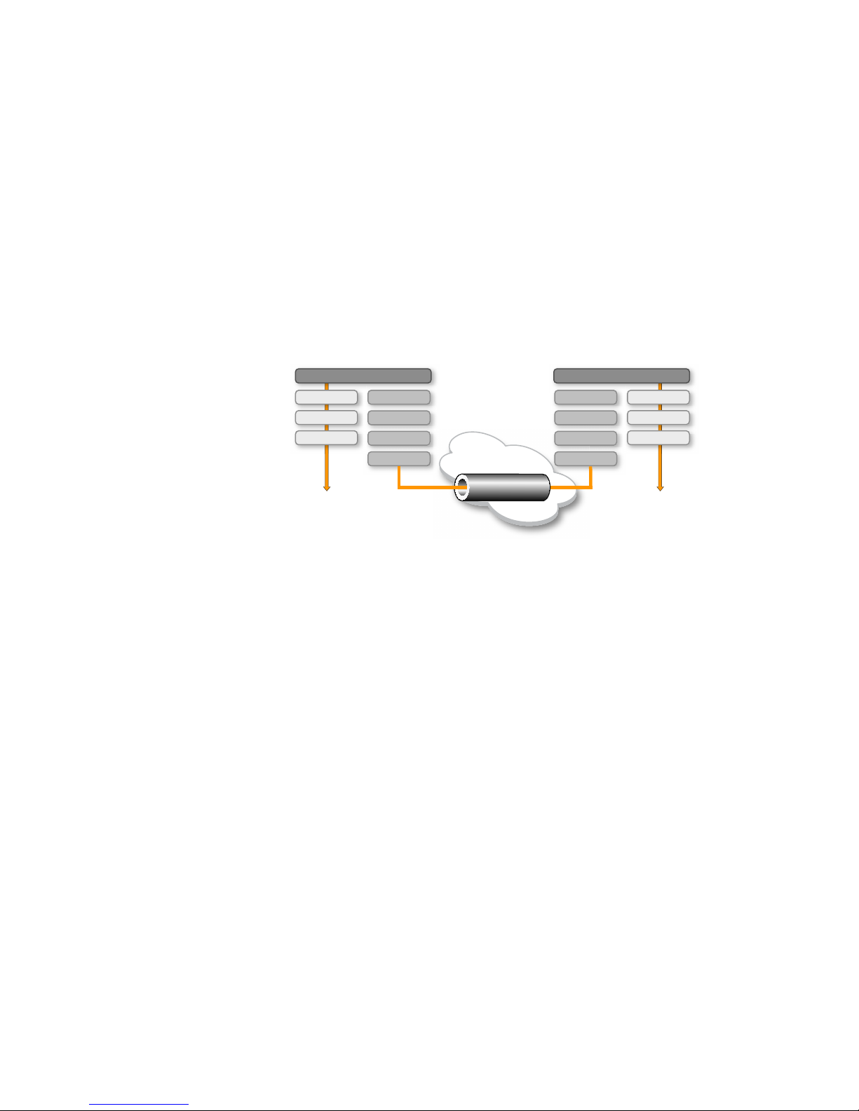
Fibre Channel over IP (FCIP) enables you to use existing IP wide area network (WAN) infrastructure
to connect Fibre Channel SANs. FCIP supports applications such as remote data replication (RDR),
centralized SAN backup, and data migration over very long distances that are impractical or very
costly using native Fibre Channel connections. FCIP tunnels are used to pass Fibre Channel I/O
through an IP network. FCIP tunnels are built on a physical connection between two peer switches
or blades. Fibre Channel frames enter FCIP through virtual E_Ports (VE_Ports or VEX_Ports) and are
encapsulated and passed to Transmission Control Protocol (TCP) layer connections. The TCP
connections ensure in-order delivery of FC frames and lossless transmission. The Fibre Channel
fabric and all Fibre Channel targets and initiators are unaware of the presence of the IP network.
Figure 1 shows the relationship of FC and TCP/IP layers, and the general concept of FCIP tunneling.
FCIP concepts
1
FIGURE 1 FCIP tunnel concept and TCP/IP layers
IP WAN network considerations
Because FCIP uses TCP connections over an existing wide area network, consult with the WAN
carrier and IP network administrator to ensure that the network hardware and software equipment
operating in the data path can properly support the TCP connections. Keep the following
considerations in mind:
• Routers and firewalls that are in the data path must be configured to pass FCIP traffic (TCP
port 3225) and IPsec traffic, if IPsec is used (UDP port 500). TCP port 3226 must be
configured for the FR4-18i only.
• To enable recovery from a WAN failure or outage, be sure that diverse, redundant network
paths are available across the WAN.
• Be sure the underlying WAN infrastructure is capable of supporting the redundancy and
performance expected in your implementation.
Fabric OS FCIP Administrator’s Guide 3
53-1002474-01

IP WAN network considerations
1
4 Fabric OS FCIP Administrator’s Guide
53-1002474-01

Chapter
FCIP on the 7800 Switch and FX8-24 Blade
In this chapter
•7800 switch hardware overview. . . . . . . . . . . . . . . . . . . . . . . . . . . . . . . . . . . . 6
•7800 switch license options. . . . . . . . . . . . . . . . . . . . . . . . . . . . . . . . . . . . . . . 7
•FX8-24 blade hardware overview . . . . . . . . . . . . . . . . . . . . . . . . . . . . . . . . . . . 8
•FX8-24 blade license options . . . . . . . . . . . . . . . . . . . . . . . . . . . . . . . . . . . . . 10
•FCIP trunking . . . . . . . . . . . . . . . . . . . . . . . . . . . . . . . . . . . . . . . . . . . . . . . . . . 15
•Adaptive Rate Limiting . . . . . . . . . . . . . . . . . . . . . . . . . . . . . . . . . . . . . . . . . . 21
•QoS SID/DID priorities over an FCIP trunk. . . . . . . . . . . . . . . . . . . . . . . . . . . 21
•QoS, DSCP, and VLANs . . . . . . . . . . . . . . . . . . . . . . . . . . . . . . . . . . . . . . . . . . 24
•Compression options. . . . . . . . . . . . . . . . . . . . . . . . . . . . . . . . . . . . . . . . . . . . 28
•IPsec implementation over FCIP tunnels . . . . . . . . . . . . . . . . . . . . . . . . . . . . 28
•Open Systems Tape Pipelining . . . . . . . . . . . . . . . . . . . . . . . . . . . . . . . . . . . . 30
•Support for IPv6 addressing . . . . . . . . . . . . . . . . . . . . . . . . . . . . . . . . . . . . . . 32
•Configuration preparation. . . . . . . . . . . . . . . . . . . . . . . . . . . . . . . . . . . . . . . . 33
•Configuration steps . . . . . . . . . . . . . . . . . . . . . . . . . . . . . . . . . . . . . . . . . . . . . 34
•Creating a multicircuit tunnel (example) . . . . . . . . . . . . . . . . . . . . . . . . . . . . 46
•Modifying an FCIP tunnel on a Brocade 7800 FX8-24 blade . . . . . . . . . . . . 49
•Modifying an FCIP circuit on a Brocade 7800 FX8-24 blade . . . . . . . . . . . . 49
•Deleting an IP interface on a Brocade 7800 FX8-24 blade . . . . . . . . . . . . . 50
•Deleting an IP route on a Brocade 7800 FX8-24 blade . . . . . . . . . . . . . . . . 50
•Deleting an FCIP tunnel on a Brocade 7800 FX8-24 blade . . . . . . . . . . . . . 50
•Deleting an FCIP circuit on a Brocade 7800 FX8-24 blade . . . . . . . . . . . . . 51
•Virtual Fabrics and the Brocade 7800 FX8-24 blade . . . . . . . . . . . . . . . . . . 51
2
Fabric OS FCIP Administrator’s Guide 5
53-1002474-01
7800 switch hardware overview
2 4
1 3
2
7800 switch hardware overview
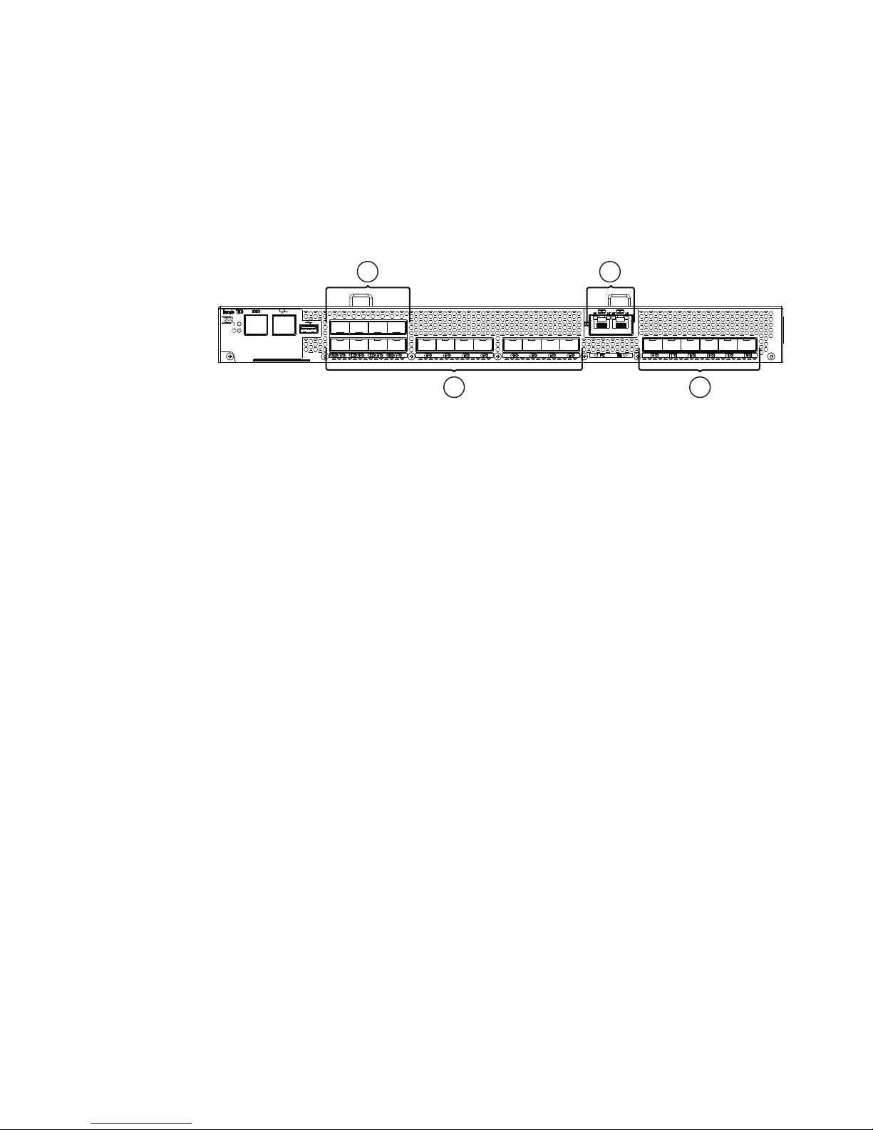
Figure 2 shows the FC ports and GbE ports on the 7800 switch. There are 16 FC ports, numbered
0 through 15. The FC ports can operate at 1, 2, 4, or 8 Gbps. There are 6 GbE ports, numbered 0
through 5. Ports 0 and 1 are available as either RJ-45 ports or small form factor pluggable (SFP)
transceiver ports. Only six total GbE ports can be used. The 6 GbE ports together can provide up to
6 Gbps total bandwidth.
1
2
FC ports 0 through 3
FC ports 4 through 15
3
4
Copper GbE ports 0 and 1 (these ports are
RJ-45 copper alternatives for GbE ports 0
and 1.)
GbE ports 0 though 5
FIGURE 2 7800 switch FC and GbE ports
The 7800 switch comes in two models:
• The 7800 4/2 base model uses FC ports 0 through 3, and GbE ports 0 and 1. The GbE ports
can be either copper or optical. The RJ-45 copper ports are the default ports. Consider the
following when using these ports:
- Copper ports do not support auto-sense functions.
- With copper media, auto-negotiation must be enabled on the other end of the port
connection. 1 Gbps is the only negotiated speed.
• The 7800 16/6 uses FC ports 0 through 15, and GbE ports 0 through 5. The 7800 upgrade
license is required. A 7800 upgrade license can be purchased for a 7800 4/2, which enables
12 more Fibre Channel ports for a total of 16, and enables the use of 4 more optical GbE ports
for a total of 6.
6 Fabric OS FCIP Administrator’s Guide
53-1002474-01

7800 switch license options
Some of the capabilities of the Brocade 7800 switch require the following feature license, as
described in Table 2.
• The Advanced FICON Acceleration License enables all FICON emulation features:
- FICON Tape Read Pipelining
- FICON Tape Write Pipelining
- FICON IBM z/OS Global Mirror (formerly eXtended Remote Copy or XRC) Emulation
- FICON Teradata Emulation
- FICON Printer Emulation
• The Integrated Routing (IR) License is required to configure VEX_Ports to support Fibre
Channel Routing (FCR).
TABLE 2 7800 FCIP feature licenses
Feature Purpose License (licenseShow output)
7800 switch license options
2
7800 upgrade Enables full hardware
capabilities, full FCIP tunnel
capabilities, support of advanced
capabilities such as open
systems tape pipelining (OSTP),
FICON CUP support, and
separately licensed advanced
FICON acceleration feature.
Advanced FICON acceleration Enables accelerated tape
read/write and IBM z/OS Global
Mirror, Teradata, and printer
emulation features in FICON
environments.
Integrated routing (IR) Required to configure VEX_Ports
to support Fibre Channel Routing
(FCR).
Advanced Extension License Required for multiple-circuit
tunnels, FCIP trunking, Adaptive
Rate Limiting (ARL), and other
FCIP features.
1. Reboot of 7800 is required after activating the 7800 upgrade license.
7800 Upgrade license
1
Advanced FICON Acceleration (FTR_AFA)
license
Integrated Routing license
Advanced Extension (FTR_AE) license
Refer to the chapter on administering licensing in the Brocade Fabric OS Administrator’s Guide for
complete information about licensing requirements.
Fabric OS FCIP Administrator’s Guide 7
53-1002474-01

FX8-24 blade hardware overview
2
VE_Ports and FCIP tunnels on the 7800 switch
A 7800 switch can support eight VE_Ports. VE_Ports are numbered from 16 through 23. Each FCIP
tunnel is identified with a VE_Port number. Up to eight FCIP tunnels can be created. The 7800
switch supports VEX_Ports to avoid the need to merge fabrics.
Consider the following when using tunnels and VE_Ports:
• On a 7800, the total bandwidth limit is 6 Gbps for VE_Ports.
• As a best practice, Fibre Channel traffic through a VE_Port tunnel should not exceed
recommended oversubscription guidelines. General guidelines include 2-to-1 oversubscription
without compression (for example, 1 Gbps over a 500 Mbps tunnel) and 4-to-1
oversubscription with compression.
• VE_Ports or VEX_Ports cannot connect to the same domain at the same time as Fibre Channel
E_Ports or EX_Ports.
FCIP trunking capacity on the 7800 switch
FCIP trunks are built by creating a set of FCIP circuits. FCIP circuits create multiple source and
destination addresses for routing traffic over a WAN, providing load leveling and failover
capabilities over an FCIP tunnel. When the 7800 upgrade license and Advanced Extension License
are activated, the FCIP trunking capacity is as follows:
• The maximum trunk capacity is 6 Gbps.
• You can define up to eight IP addresses for a GbE port.
• There is a hard limit of four FCIP circuits per GbE port, each requiring a unique IP address.
• Up up to six FCIP circuits can be defined per FCIP tunnel. These circuits can be spread out over
any GbE ports.
• A single FCIP circuit cannot exceed 1 Gbps capacity.
FX8-24 blade hardware overview
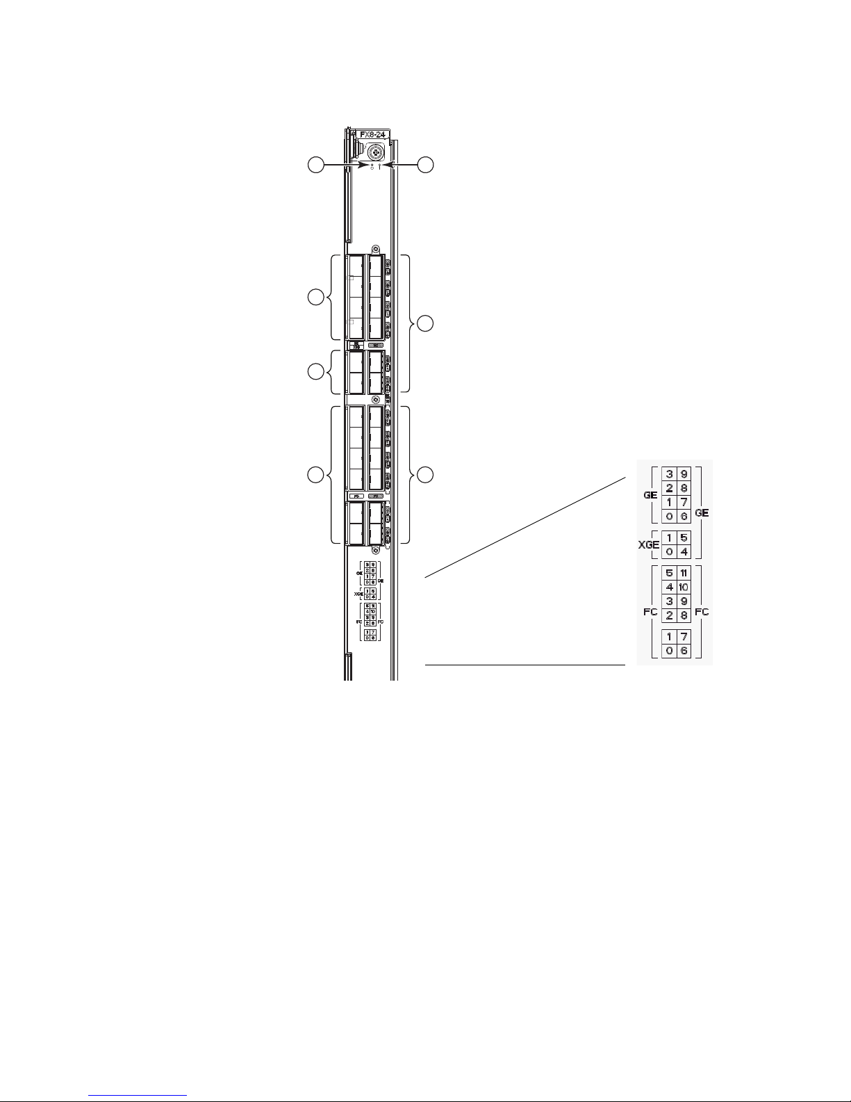
Figure 3 on page 9 shows the FC ports, GbE ports, and 10GbE ports on the FX8-24 blade. There
are 12 FC ports, numbered 0 through 11. The FC ports can operate at 1, 2, 4, or 8 Gbps. There are
10 GbE ports, numbered 0 through 9. Ports xge0 and xge1 are 10GbE ports.
The FX8-24 blade allows a maximum of 20 Gbps of bandwidth for tunnel connections, and can
operate in one of three different modes:
• 1 Gbps mode - You can use all ten GbE ports (0 through 9). Both XGE ports are disabled.
• 10 Gbps mode - You can use the xge0 and xge1 ports.
• Dual mode - You can use GbE ports 0 through 9, and port xge0.
The FX8-24 blade can be deployed in either a DCX, DCX-4S, DCX 8510-8, or DCX 8510-4 chassis.
8 Fabric OS FCIP Administrator’s Guide
53-1002474-01
FX8-24 blade hardware overview
2
1
5
4
3
76
2
1
2
3
4
10GbE ports (Labeled xge0 and xge1
on the sticker.)
GbE ports 0 through 3
GbE ports 4 through 9
FC ports 6 through 11
FIGURE 3 FX8-24 blade FC and GbE ports
5
6
7
FC ports 0 through 5
Power LED
Status LED
Fabric OS FCIP Administrator’s Guide 9
53-1002474-01

FX8-24 blade license options
ATTENTION
2
Removing FX8-24 blades
If you are permanently removing a blade from a DCX, DCX-4S, DCX 8510-8, or DCX 8510-4 chassis
to relocate to another slot in the chassis or you are removing the blade from the chassis entirely, you
must follow these procedures before removing the blade.
• Remove all FCIP configuration settings for the blade. If there are residual configuration
settings, they may cause issues with future configurations and upgrades.
• Delete the IP addresses assigned to the original slot using the portcfg ipif delete command. If
this is not done, you must return the FX8-24 blade to the original slot and delete the IP
addresses.
FX8-24 blade license options
Some of the capabilities of the FX8-24 blade require the slot-based feature licenses shown in
Tab le 3. Use the licenseshow command to display license keys and licenses currently installed.
TABLE 3 FX8-24 FCIP feature licenses
Feature Purpose License (licenseShow output)
10GbE support Allows 10 Gbps operation on 10
GbE ports.
Advanced FICON acceleration Enables accelerated tape
read/write and IBM z/OS Global
Mirror, Teradata, and printer
emulation features in FICON
environments.
Integrated routing (IR) Required to configure VEX_Ports
to support Fibre Channel Routing
(FCR).
Advanced Extension License Required for multiple-circuit
tunnels, FCIP trunking, Adaptive
Rate Limiting (ARL), and other
FCIP features.
Refer to the administering licensing chapter in the Fabric OS Administrator’s Guide for complete
information about licensing requirements.
10 Gigabit FCIP/Fibre Channel (FTR_10G)
license
Advanced FICON Acceleration (FTR_AFA)
license
Integrated Routing license
Advanced Extension (FTR_AE) license
VE_Ports and FCIP tunnels on the FX8-24 blade
An FX8-24 blade can support 20 VE_Ports, and therefore 20 FCIP tunnels.There are two VE_Port
groups, numbered 12 through 21 and 22 through 31. Each FCIP tunnel is associated with a specific
VE_Port.
VE_Ports do not have to be associated with a particular GbE port on FX8-24 blades and the 7800
switch. VE_Port versus GbE port usage depends on the blade operating mode as follows:
• 1 Gbps mode: VE_Ports 12 through 21 use GbE ports 0 through 9
• Dual mode: VE_Ports 12 through 21 use GbE ports 0 through 9; VE_Ports 22 through 31 use
xge0
10 Fabric OS FCIP Administrator ’s Guide
53-1002474-01

FX8-24 blade license options
NOTE
2
• 10 Gbps mode: VE_Ports 12 through 21 use xge1; VE_Ports 22 through 31 use xge0
In 10 Gbps mode, you can also configure VE_Ports 12 through 21 to use port xge0 as a
crossport and VE_Ports 22 through 31 to use port xge1 as a crossport. Refer to “Crossports”
on page 13 for more information.
Considerations for using VE_Ports and FCIP tunnels
Consider the following when using VE_Ports and tunnels:
• Total bandwidth cannot exceed 20 Gbps for VE_Ports.
• As a best practice, Fibre Channel traffic through a VE_Port tunnel should not exceed
recommended oversubscription guidelines. General guidelines include 2-to-1 oversubscription
without compression (for example, 1 Gbps over a 500 Mbps tunnel) and 4-to-1
oversubscription with compression.
• VE_Ports or VEX_Ports cannot connect to the same domain at the same time as Fibre Channel
E_Ports or EX_Ports.
FCIP trunking capacity on the FX8-24 blade
FCIP trunking provides load leveling and failover capabilities through the use of multiple FCIP
circuits:
• FCIP tunnels using 1 GbE or 10 GbE ports can have up to ten FCIP circuits spread across any
GbE ports.
• You can define up to eight IP addresses (0 through 8 minus the default IPv6 “link-local”
address) for a GbE port.
• Up to four FCIP circuits can be configured per 1 GbE port, each requiring a unique IP address.
• Up to ten FCIP circuits can be configured per 10 GbE port, each requiring a unique IP address.
• A single circuit between 1 GbE ports cannot exceed 1 Gbps capacity.
10 GbE port considerations
Enhanced 10GbE port operation is different than 1 GbE port operation and requires special
considerations when configuring circuits, tunnels, failover operations, and bandwidth.
Multigigabit circuits
For each 10 GbE port, you can configure multigigabit circuits. For example, a single 10 Gbps circuit
or two 5 Gbps circuits can be configured per port. A limit of 10 FCIP circuits can be configured on a
single port. The blade at each end of the tunnel must be running Fabric OS v7.0 and later if the
committed rate for circuits exceeds 1 Gbps.The maximum committed rate for a circuit between 10
GbE ports is 10 Gbps.
Fabric OS FCIP Administrator’s Guide 11
53-1002474-01

FX8-24 blade license options
NOTE
NOTE
2
Bandwidth allocation and restrictions
You cannot configure more than 10 Gbps of dedicated bandwidth on a 10GbE port. This includes
both primary and secondary circuits. Following are two examples to clarify these requirements.
In the following examples, configuring VE_Port 12 on xge0 is a crossport configuration. For more
information on crossports, refer to “Configuring crossports” on page 13.
The terms “XGE port” and “GbE port” may be used interchangeably in this document.
• VE_Port 12 has two 10 Gbps circuits. Circuit 0 has a metric of 0 on xge1 and circuit 1 has a
• VE_Port 12 has two 10 Gbps circuits. Circuit 0 has a metric of 0 on xge1, and circuit 1 has a
metric 1 on xge0. With this configuration, no other tunnels or circuits would be allowed on this
blade because both XGE ports have 10 Gbps of configured bandwidth.
metric of 1 on xge0. In this case, the configuration is allowed, but you could not create
additional circuits for either VE port group. For the VE_Port 12-21 port group, VE_Port 12 is
consuming 10 Gbps of back end port bandwidth, so additional circuits from another tunnel
could not be created. For the VE_Port 22-31 group, the bandwidth would exceed either the
front end port bandwidth or the crossport bandwidth. Again VE_Port 12 circuit 1 is consuming
10 Gbps of crossport bandwidth and 10 Gbps of front end port bandwidth for xge0, so you
cannot create additional circuits for VE_Port 22-31 group.
Note that there can only be a maximum of 10 Gbps defined over the crossport configuration.
Therefore, in the preceding example, since VE_Port 12 is configured with a single 10 Gbps
circuit over xge0 (which would be the crossport for VE_Port 12-21 group), there can be no other
crossport configurations. You could not configure a crossport for VE_Port 22-31 port group
because VE_Port 12 is using all 10 Gbps bandwidth for xge0. This would also restrict you from
configuring any circuits for VE_Ports 22-31 at all. Therefore, consuming the crossport
bandwidth for primary metric 0 circuits is not recommended. Refer to “Crossport bandwidth
allocation” on page 15 for more information.
Back-end bandwidth
Back-end port bandwidth allocation is calculated as follows:
• Back-end bandwidths are always rounded up to the nearest 1 Gbps. For example, 1.5 Gbps
actually consumes 2 Gbps of back-end bandwidth.
• Each VE_Port group is allocated 10 Gbps of back-end bandwidth (10 Gbps for the VE_Port
12-21 group and 10 Gbps for the VE_Port 22-31 group).
• The total back-end port bandwidth allocation is calculated by adding up the consumed
bandwidth for each FCIP tunnel in the VE_Port group.
• The consumed bandwidth for a given FCIP tunnel is calculated by adding the maximum
committed rates (rounded to the nearest 1 Gbps) for all metric 0 circuits, adding up the
maximum committed rates (also rounded to the nearest 1 Gbps) for all metric 1 circuits, then
taking the greater of the two values.
12 Fabric OS FCIP Administrator ’s Guide
53-1002474-01

FX8-24 blade license options
NOTE
Front-end bandwidth
Front-end port bandwidth allocation is calculated as follows:
2
• Each 10 GbE port is allocated 10 Gbps of front-end bandwidth. The total front-end port
bandwidth allocation cannot exceed 10 Gbps per 10 GbE port.
• The total front-end port bandwidth allocation is calculated by adding up the consumed
bandwidth for each FCIP tunnel using that XGE port.
• The consumed bandwidth for a given FCIP tunnel is calculated by adding up the maximum
committed rates (not rounded) for all metric 0 circuits using that XGE port, adding up the
maximum rates (not rounded) for all metric 1 circuits using that XGE port, then taking the
greater of the two values.
Crossports
Crossports are addresses and routes that belong to the other 10GbE (XGE) port’s DP or VE group.
The crossport for xge0 is xge1 and for xge1, the crossport is xge0. To use crossports, the port must
be configured in 10 Gbps mode.
XGE and GbE port may be used interchangeably in this document.
You can configure IP addresses on crossports, configure a circuit with metrics for circuit failover on
crossports, and configure VE_Ports that are normally available on the a local XGE port to operate
through a crossport. The crossport is the non-local XGE port for a VE_Port group. In other words, for
VE ports 12 through 21, xge1 is the local XGE port and xge0 is the crossport. For VE ports 22
through 31, xge0 is the local XGE port and xge1 is the crossport.
Configuring crossports
Configure crossport XGE port addresses using the --crossport or -x (shorthand) options for the
portcfg ipif command, as shown in the following example. Note that in this example, IP address
192.168.11.20, created for a FX8-24 blade in slot 8 on port xge0 will be available for circuits on VE
ports 12 through 21.
portcfg ipif 8/xge0 create 192.168.11.20 255.255.255.0 1500 --crossport
or
portcfg ipif 8/xge0 create 192.168.11.20 255.255.255.0 1500 –x
Delete the crossport address using the delete option instead of the create option for the portcfg ipif
command.
portcfg ipif 8/xge0 delete 192.168.11.20 255.255.255.0 1500 –x
Configuring 10GbE lossless failover with crossports
Refer to “10GbE lossless failover” on page 18.
Fabric OS FCIP Administrator’s Guide 13
53-1002474-01

FX8-24 blade license options
NOTE
NOTE
2
Configuring IP routes with crossports
You can configure IP routes with crossport addresses, as in the following example. In the example,
the route will be available for FCIP tunnel circuits using VE ports 12 through 21.
portcfg iproute 8/xge0 create 1.1.1.0 255.255.255.0 192.168.11.250 --crossport
or
portcfg iproute 8/xge0 create 1.1.1.0 255.255.255.0 192.168.11.250 –x
Delete the route using the delete option instead of the create option for the portcfg iproute
command.
portcfg iproute 8/xge0 delete 1.1.1.0 255.255.255.0 -x
For more information on configuring an IP route, refer to “Configuring an IP route” on page 37.
If an XGE port has both regular and crossport addresses configured on it, and they use the same IP
route, then two routes will need to be configured—a regular route and an identical route on the cross
port.
Configuring VLAN tags with crossports
Add entries with crossport addresses to the VLAN tag table, as in the following example. This
example allows VE ports 12 through 21 to use the configured local IP interface with this VLAN tag.
portcfg vlantag 8/xge0 add 192.168.11.20 200 1 --crossport
or
portcfg vlantag 8/xge0 add 192.168.11.20 200 1 –x
Delete the VLAN tag using the delete option instead of the add option for the portcfg vlantag
command.
portcfg vlantag 8/xge0 delete 192.168.11.20 200 1 –x
To tag Class-F traffic or data path traffic, use the -v, - -vlan-tagging option on the fcipcircuit create or
fcipcircuit modify command.
For more information on managing VLAN tags, refer to “Managing the VLAN tag table” on page 26.
Using ping with crossports
You can ping crossport addresses as in the following example. Note that if the crossport or x
options are not specified and the address is on the crossport, the portcmd command will fail with
an unknown IP address.
portcmd --ping 8/xge0 -s 192.168.11.20 -d 1.1.1.1 --crossport
or
portcmd --ping 8/xge0 -s 192.168.11.20 -d 1.1.1.1 –x
For more information on using ping, refer to “Using ping to test a connection” on page 84.
14 Fabric OS FCIP Administrator ’s Guide
53-1002474-01

FCIP trunking
FCIP Circuits
IP Router
10.0.0.1
IP Router
10.0.1.1
10.0.0.2
10.0.0.3
10.0.0.4
10.0.0.5
FCIP Circuits
FCIP Tunnel
WAN
10.0.1.2
10.0.1.3
10.0.1.4
10.0.1.5
2
Using traceroute with crossports
You can trace a route to a crossport address, as in the following example. Note that if the crossport
or x options are not specified and the address is on the crossport, the portcmd command will fail
with an unknown IP address.
portcmd --traceroute 8/xge0 -s 192.168.11.20 -d 1.1.1.1 –x
or
portcmd --traceroute 8/xge0 -s 192.168.11.20 -d 1.1.1.1 --crossport
For more information on using traceroute, refer to “Using traceroute” on page 84.
Crossport bandwidth allocation
There is a total of 10 Gbps crossport bandwidth allocation for the entire FX8-24 blade. The total
crossport bandwidth cannot exceed 10 Gbps for all VE_Ports on the blade. Crossport bandwidth
allocation for 10GbE ports is calculated as follows
• The total crossport bandwidth allocation is calculated by adding up the consumed bandwidth
for every FCIP tunnel using a crossport IP address.
• The consumed bandwidth for each FCIP tunnel is calculated by adding up the maximum
committed rates (not rounded) for all metric 0 circuits that use a crossport IPIF, and then
adding up the maximum rates (not rounded) for all metric 1 circuits.
FCIP trunking
FCIP trunking is a method for managing the use of WAN bandwidth and providing redundant paths
over the WAN that can protect against transmission loss due to WAN failure. Trunking is enabled by
creating logical circuits within an FCIP tunnel. A tunnel can have multiple circuits. You can configure
up to 6 circuits on tunnels between 7800 switches and up to 10 on tunnels between FX8-24
blades. Each circuit is a connection between a pair of IP addresses that are associated with source
and destination endpoints of an FCIP tunnel, as shown in Figure 4.
FIGURE 4 FCIP tunnel and FCIP circuits
Fabric OS FCIP Administrator’s Guide 15
53-1002474-01

2
FCIP trunking
Design for redundancy and fault tolerance
Multiple FCIP tunnels can be defined between pairs of 7800 switches or FX8-24 blades, but doing
so defeats the concept of a multiple circuit FCIP tunnel. Defining two tunnels between a pair of
switches or blades is not as redundant or fault tolerant as having multiple circuits in one tunnel.
FCIP tunnel restrictions for FCP and FICON acceleration features
Multiple FCIP tunnels are not supported between pairs of 7800 switches or FX8-24 blades when
any of the FICON emulation/acceleration features or FCP acceleration features are enabled on the
tunnel, unless TI Zones or LS/LF configurations are used to provide deterministic flows between
the switches. These features require deterministic FC Frame routing between all initiators and
devices over multiple tunnels. Noncontrolled, parallel (equal-cost) tunnels are not supported
between the switch pairs when emulation is enabled on any one or more tunnels without
controlling the routing of SID/DID pairs to individual tunnels using TI Zones or LS/LF
configurations.
Note these additional restrictions:
• FICON networks with FCIP emulating and nonemulating tunnels do not support DPS (aptpolicy
3) configurations.
• If one end of a FICON emulating tunnel runs Fabric OS v7.0.0 or later, both ends of the tunnel
must run Fabric OS v7.0.0 or later.
FCIP circuits
The following list describes FCIP circuit characteristics, restrictions, and usage:
• General tunnel and circuit requirements:
- A circuit can have a maximum commit rate of 1 Gbps on 1 GbE ports or 10 Gbps on 10
GbE ports.
- The minimum committed rate allowed on a circuit is 10 Mbps.
- In a scenario where an FCIP tunnel has multiple circuits of different metrics, circuits with
higher metrics are treated as standby circuits and are not used until all lower metric
circuits fail. Refer to “FCIP circuit failover capabilities” for a more detailed description.
- A circuit defines source and destination IP addresses on either end of an FCIP tunnel.
- If the circuit source and destination IP addresses are not on the same subnet, an IP static
route must be defined that designates the gateway IP address.
- There are no addressing restrictions for IPv6 and IPv4 when using switches or blades
operating with Fabric OS v7.0.0 or later.
- Committed bandwidth on both sides of the tunnels and circuits must be the same.
- When load leveling across multiple circuits, the difference between the committed rate of
the slowest circuit in the FCIP trunk and the fastest circuit should be no greater than a
factor of four (for example, a 100 Mbps and a 400 Mbps circuit will work, but a 10 Mbps
and a 400 Mbps circuit will not work). This ensures that the entire bandwidth of the FCIP
trunk can be utilized. If you configure circuits with the committed rates that differ by more
than a factor of four, the entire bandwidth of the FCIP trunk cannot be fully utilized.
16 Fabric OS FCIP Administrator ’s Guide
53-1002474-01
 Loading...