

Brocade Communications Systems A7533A - Brocade 4Gb SAN Switch Base, AE370A - Brocade 4Gb SAN Switch 4/12 Administrator's Manual
Page 1

53-1000605-02
12 Mar 2008
Access Gateway
Administrator’s Guide
Supporting Fabric OS v6.1.0
Page 2

Copyright © 2007-2008 Brocade Communications Systems, Inc. All Rights Reserved.
Brocade, Fabric OS, File Lifecycle Manager, MyView, and StorageX are registered trademarks and the Brocade B-wing symbol,
DCX, and SAN Health are trademarks of Brocade Communications Systems, Inc., in the United States and/or in other countries.
All other brands, products, or service names are or may be trademarks or service marks of, and are used to identify, products or
services of their respective owners.
Notice: This document is for informational purposes only and does not set forth any warranty, expressed or implied, concerning
any equipment, equipment feature, or service offered or to be offered by Brocade. Brocade reserves the right to make changes to
this document at any time, without notice, and assumes no responsibility for its use. This informational document describes
features that may not be currently available. Contact a Brocade sales office for information on feature and product availability.
Export of technical data contained in this document may require an export license from the United States government.
The authors and Brocade Communications Systems, Inc. shall have no liability or responsibility to any person or entity with
respect to any loss, cost, liability, or damages arising from the information contained in this book or the computer programs that
accompany it.
The product described by this document may contain “open source” software covered by the GNU General Public License or other
open source license agreements. To find-out which open source software is included in Brocade products, view the licensing
terms applicable to the open source software, and obtain a copy of the programming source code, please visit
http://www.brocade.com/support/oscd.
Page 3

Brocade Communications Systems, Incorporated
Corporate Headquarters
Brocade Communications Systems, Inc.
1745 Technology Drive
San Jose, CA 95110
Tel: 1-408-333-8000
Fax: 1-408-333-8101
Email: info@brocade.com
European and Latin American Headquarters
Brocade Communications Switzerland Sàrl
Centre Swissair
Tour A - 2ème étage
29, Route de l'Aéroport
Case Postale 105
CH-1215 Genève 15
Switzerland
Tel: +41 22 799 56 40
Fax: +41 22 799 56 41
Email: emea-info@brocade.com
Asia-Pacific Headquarters
Brocade Communications Singapore Pte. Ltd.
9 Raffles Place
#59-02 Republic Plaza 1
Singapore 048619
Tel: +65-6538-4700
Fax: +65-6538-0302
Email: apac-info@brocade.com
Document History
The following table lists all versions of the Access Gateway Administrator’s Guide.
Document Title Publication Number Summary of Changes Publication Date
Access Gateway Administrator’s Guide 53-1000430-01 First version January 2007
Access Gateway Administrator’s Guide 53-1000633-01 Added support for the 200E 15 Jun 2007
Access Gateway Administrator’s Guide 53-1000605-01 Added support for new policies
and changes to N_Port
mappings.
Access Gateway Administrator’s Guide 53-1000605-02 Added support for new
platforms:
300 and the 4424.
Added support for new features:
- Masterless Trunking
- Direct Target Connectivity
- Advance Device Security policy
- 16- bit routing
19 Oct 2007
12 Mar 2008
Access Gateway Administrator’s Guide iii
53-1000605-02
Page 4

iv Access Gateway Administrator’s Guide
53-1000605-02
Page 5

Contents
About This Document
How this document is organized . . . . . . . . . . . . . . . . . . . . . . . . . . . . vii
Supported hardware and software . . . . . . . . . . . . . . . . . . . . . . . . . . vii
What’s new in this document. . . . . . . . . . . . . . . . . . . . . . . . . . . . . . . viii
Document conventions. . . . . . . . . . . . . . . . . . . . . . . . . . . . . . . . . . . . viii
Text formatting . . . . . . . . . . . . . . . . . . . . . . . . . . . . . . . . . . . . . . . viii
Notes, cautions, and warnings . . . . . . . . . . . . . . . . . . . . . . . . . . .ix
Key terms. . . . . . . . . . . . . . . . . . . . . . . . . . . . . . . . . . . . . . . . . . . . . . . . ix
Additional information. . . . . . . . . . . . . . . . . . . . . . . . . . . . . . . . . . . . . . x
Brocade resources. . . . . . . . . . . . . . . . . . . . . . . . . . . . . . . . . . . . . x
Other industry resources. . . . . . . . . . . . . . . . . . . . . . . . . . . . . . . . x
Optional Brocade features . . . . . . . . . . . . . . . . . . . . . . . . . . . . . . xi
Getting technical help. . . . . . . . . . . . . . . . . . . . . . . . . . . . . . . . . . . . . . xi
Document feedback . . . . . . . . . . . . . . . . . . . . . . . . . . . . . . . . . . . . . . xii
Chapter 1 Getting Started
In this chapter . . . . . . . . . . . . . . . . . . . . . . . . . . . . . . . . . . . . . . . . . . . . 1
Brocade Access Gateway . . . . . . . . . . . . . . . . . . . . . . . . . . . . . . . . . . . 1
Fabric OS features in Access Gateway mode . . . . . . . . . . . . . . . . 2
Access Gateway port types . . . . . . . . . . . . . . . . . . . . . . . . . . . . . . . . . . 3
Comparison of Access Gateway ports to standard switch ports. 3
How Access Gateway maps ports . . . . . . . . . . . . . . . . . . . . . . . . . . . . 4
Upgrade and downgrade considerations. . . . . . . . . . . . . . . . . . . . . . . 5
Considerations with policies enabled. . . . . . . . . . . . . . . . . . . . . . 5
Advance Device Security policy. . . . . . . . . . . . . . . . . . . . . . . . . . . 5
Automatic Port Configuration policy . . . . . . . . . . . . . . . . . . . . . . . 5
Port Grouping policy. . . . . . . . . . . . . . . . . . . . . . . . . . . . . . . . . . . . 5
Chapter 2 Enabling Policies on Switches in Access Gateway Mode
In this chapter . . . . . . . . . . . . . . . . . . . . . . . . . . . . . . . . . . . . . . . . . . . . 7
Access Gateway Administrator’s Guide iii
53-1000605-02
Page 6

Access Gateway policies . . . . . . . . . . . . . . . . . . . . . . . . . . . . . . . . . . . . 8
Showing current policies . . . . . . . . . . . . . . . . . . . . . . . . . . . . . . . . 8
Advance Device Security policy. . . . . . . . . . . . . . . . . . . . . . . . . . . 8
Enabling the Advance Device Security policy. . . . . . . . . . . . . . . . 9
Disabling the Advance Device Security policy . . . . . . . . . . . . . . . 9
Setting which devices can log in if ADS policy is enabled. . . . . . 9
Setting which devices cannot log in if ADS policy is enabled . .10
Removing devices from the list of devices allowed at login . . . 10
Adding new devices to the list of devices allowed at login . . . . 10
Displaying the list of devices on the switch . . . . . . . . . . . . . . . .11
Automatic Port Configuration policy . . . . . . . . . . . . . . . . . . . . . .11
Enabling the Automatic Port Configuration policy . . . . . . . . . . .12
Disabling the Automatic Port Configuration policy . . . . . . . . . .12
Rebalancing F_Ports with APC policy enabled . . . . . . . . . . . . . .12
Failover Policy . . . . . . . . . . . . . . . . . . . . . . . . . . . . . . . . . . . . . . . .13
Enabling the Failover policy. . . . . . . . . . . . . . . . . . . . . . . . . . . . .14
Disabling the Failover policy . . . . . . . . . . . . . . . . . . . . . . . . . . . .15
Failback policy . . . . . . . . . . . . . . . . . . . . . . . . . . . . . . . . . . . . . . . 15
Enabling the Failback policy . . . . . . . . . . . . . . . . . . . . . . . . . . . . 16
Cold Failover policy . . . . . . . . . . . . . . . . . . . . . . . . . . . . . . . . . . . 17
Port Grouping policy. . . . . . . . . . . . . . . . . . . . . . . . . . . . . . . . . . . 17
Creating a port group. . . . . . . . . . . . . . . . . . . . . . . . . . . . . . . . . . 19
Adding an N_Port to a port group . . . . . . . . . . . . . . . . . . . . . . . .20
Deleting an N_Port from a port group . . . . . . . . . . . . . . . . . . . . 20
Removing a port group . . . . . . . . . . . . . . . . . . . . . . . . . . . . . . . .20
Renaming a port group . . . . . . . . . . . . . . . . . . . . . . . . . . . . . . . . 21
Disabling the Port Group policy. . . . . . . . . . . . . . . . . . . . . . . . . . 21
Access Gateway policy enforcement matrix . . . . . . . . . . . . . . . .21
Access Gateway N_Port trunking . . . . . . . . . . . . . . . . . . . . . . . . . . . .22
Access Gateway trunking considerations . . . . . . . . . . . . . . . . . .23
Trunk group creation . . . . . . . . . . . . . . . . . . . . . . . . . . . . . . . . . .25
Setting up F_Port trunking . . . . . . . . . . . . . . . . . . . . . . . . . . . . .26
Assigning a Trunk Area . . . . . . . . . . . . . . . . . . . . . . . . . . . . . . . .26
Enabling the DCC policy on trunk . . . . . . . . . . . . . . . . . . . . . . . . 27
Configuration management for trunk areas . . . . . . . . . . . . . . . 28
Enabling Access Gateway trunking . . . . . . . . . . . . . . . . . . . . . . .28
Disabling F_Port trunking . . . . . . . . . . . . . . . . . . . . . . . . . . . . . .29
F_Port Trunking monitoring . . . . . . . . . . . . . . . . . . . . . . . . . . . . .30
Chapter 3 Connecting Devices Using Access Gateway
iv Access Gateway Administrator’s Guide
In this chapter . . . . . . . . . . . . . . . . . . . . . . . . . . . . . . . . . . . . . . . . . . . 31
Configuring the fabric and edge switch. . . . . . . . . . . . . . . . . . . . . . .32
Verifying the switch mode . . . . . . . . . . . . . . . . . . . . . . . . . . . . . .32
Setting the Fabric OS switch to Native Mode. . . . . . . . . . . . . . .33
Enabling NPIV on the M-EOS switch . . . . . . . . . . . . . . . . . . . . . .33
53-1000605-02
Page 7

Connectivity to Cisco Fabrics . . . . . . . . . . . . . . . . . . . . . . . . . . . . . . .34
Access Gateway routing requirements with Cisco fabrics. . . . . 34
Enabling NPIV on a Cisco switch. . . . . . . . . . . . . . . . . . . . . . . . .34
Workaround for QLogic-based devices . . . . . . . . . . . . . . . . . . . .35
Editing Company ID List if no FC target devices on switch . . . .35
Adding or deleting an OUI from the Company ID List . . . . . . . .36
Enabling Flat FCID mode if no FC target devices on switch . . . 37
Editing Company ID list if target devices on switch. . . . . . . . . . 37
Access Gateway mode . . . . . . . . . . . . . . . . . . . . . . . . . . . . . . . . . . . .38
Enabling Access Gateway mode . . . . . . . . . . . . . . . . . . . . . . . . .38
Port States . . . . . . . . . . . . . . . . . . . . . . . . . . . . . . . . . . . . . . . . . .39
Disabling Access Gateway mode . . . . . . . . . . . . . . . . . . . . . . . .40
Re-joining switches to a fabric . . . . . . . . . . . . . . . . . . . . . . . . . . . . . . 41
Reverting to a previous configuration. . . . . . . . . . . . . . . . . . . . . 41
Chapter 4 Configuring Ports in Access Gateway mode
In this chapter . . . . . . . . . . . . . . . . . . . . . . . . . . . . . . . . . . . . . . . . . . .43
Port Initialization in Access Gateway mode. . . . . . . . . . . . . . . . . . . .43
N_Ports . . . . . . . . . . . . . . . . . . . . . . . . . . . . . . . . . . . . . . . . . . . . . . . .44
Unlocking N_Ports . . . . . . . . . . . . . . . . . . . . . . . . . . . . . . . . . . . .45
Displaying N_Port configurations . . . . . . . . . . . . . . . . . . . . . . . .46
Verifying port mapping and status . . . . . . . . . . . . . . . . . . . . . . . 46
Displaying N_Port mapping. . . . . . . . . . . . . . . . . . . . . . . . . . . . .47
Displaying port status . . . . . . . . . . . . . . . . . . . . . . . . . . . . . . . . . 47
Port configurations . . . . . . . . . . . . . . . . . . . . . . . . . . . . . . . . . . . . . . .48
Adding F_Ports to an N_Port. . . . . . . . . . . . . . . . . . . . . . . . . . . .48
Removing F_Ports from an N_Port . . . . . . . . . . . . . . . . . . . . . . .49
Adding a preferred secondary N_Port . . . . . . . . . . . . . . . . . . . .50
Deleting F_Ports from a preferred secondary N_Port . . . . . . . .50
Appendix A Troubleshooting
Index
Access Gateway Administrator’s Guide v
53-1000605-02
Page 8

vi Access Gateway Administrator’s Guide
53-1000605-02
Page 9

About This Document
This document is a procedural guide to help SAN administrators configure and manage Brocade
Access Gateway.
This preface contains the following sections:
•How this document is organized . . . . . . . . . . . . . . . . . . . . . . . . . . . . . . . . . . vii
•Supported hardware and software. . . . . . . . . . . . . . . . . . . . . . . . . . . . . . . . . vii
•What’s new in this document . . . . . . . . . . . . . . . . . . . . . . . . . . . . . . . . . . . . . viii
•Document conventions . . . . . . . . . . . . . . . . . . . . . . . . . . . . . . . . . . . . . . . . . . viii
•Key terms . . . . . . . . . . . . . . . . . . . . . . . . . . . . . . . . . . . . . . . . . . . . . . . . . . . . . . ix
•Additional information. . . . . . . . . . . . . . . . . . . . . . . . . . . . . . . . . . . . . . . . . . . . x
•Getting technical help . . . . . . . . . . . . . . . . . . . . . . . . . . . . . . . . . . . . . . . . . . . . xi
•Document feedback . . . . . . . . . . . . . . . . . . . . . . . . . . . . . . . . . . . . . . . . . . . . xii
How this document is organized
The document contains the following topics:
• Chapter 1, “Getting Started” describes how to use Access Gateway to create seamless
connectivity to any Storage Area Network (SAN) fabric.
• Chapter 2, “Enabling Policies on Switches in Access Gateway Mode”describes how to enable
policies on a switch in Access Gateway mode.
• Chapter 3, “Connecting Devices Using Access Gateway” describes how to connect multiple
devices using Access Gateway.
• Chapter 4, “Configuring Ports in Access Gateway mode” describes how to configure ports in
Access Gateway mode.
• Appendix A, “Troubleshooting” provides symptoms and troubleshooting tips to resolve issues.
Supported hardware and software
Although many different software and hardware configurations are tested and supported by
Brocade Communications Systems, Inc. For v6.1.0, documenting all possible configurations and
scenarios is beyond the scope of this document. All Fabric OS switches must be running v5.1 or
later; all M-EOS switches must be running M-EOSc 9.1 or later, M-EOSn must be running 9.6.2 or
later, and Cisco switches with SAN OS must be running 3.0 (1) and 3.1 (1) or later. Access Gateway
supports 4 and 8 Gbit bladed servers and blades.
Access Gateway Administrator’s Guide vii
53-1000605-02
Page 10

What’s new in this document
The following changes have been made since this document was last released:
Information that was added
• Platforms
• Brocade 300 and 4424
• 16-bit routing (8 Gbps platforms only)
• Performance
• Access Gateway masterless trunking
• Seamless failover
• Configuration
• Direct Target Attach
• Security
• Advance Device Security policy
• Enhanced routing
For further information, refer to the release notes.
Document conventions
This section describes text formatting conventions and important notices formats.
Text formatting
The narrative-text formatting conventions that are used in this document are as follows:
bold text Identifies command names
Identifies the names of user-manipulated GUI elements
Identifies keywords and operands
Identifies text to enter at the GUI or CLI
italic text Provides emphasis
Identifies variables
Identifies paths and Internet addresses
Identifies document titles
code text Identifies CLI output
Identifies syntax examples
For readability, command names in the narrative portions of this guide are presented in mixed
lettercase: for example, switchShow. In actual examples, command lettercase is often all
lowercase. Otherwise, this manual specifically notes those cases in which a command is case
sensitive. The ficonCupSet and ficonCupShow commands are an exception to this convention.
viii Access Gateway Administrator’s Guide
53-1000605-02
Page 11

Notes, cautions, and warnings
NOTE
ATTENTION
CAUTION
DANGER
The following notices appear in this document.
A note provides a tip, emphasizes important information, or provides a reference to related
information.
An Attention statement indicates potential damage to hardware or data.
A Caution statement alerts you to situations that can be potentially hazardous to you.
A Danger statement indicates conditions or situations that can be potentially lethal or extremely
hazardous to you. Safety labels are also attached directly to products to warn of these conditions
or situations.
Key terms
For definitions of SAN-specific terms, visit the Storage Networking Industry Association online
dictionary at: http://www.snia.org/education/dictionary.
For definitions specific to Brocade and Fibre Channel, see the Brocade Glossary.
The following terms are used in this manual to describe Access Gateway mode and its
components.
Access Gateway (AG)
Fabric OS mode for embedded switches that reduces SAN (storage area
network) deployment complexity by leveraging NPIV (N_Port ID virtualization).
E_Port An ISL (Interswitch link) port. A switch port that connects switches together to
form a fabric.
Edge switch A fabric switch that connects host, storage, or other devices, such as Brocade
Access Gateway, to the fabric.
F_Port A fabric port. A switch port that connects a host, HBA (host bus adaptor), or
storage device to the SAN. On Brocade Access Gateway, the F_Port connects
to a host only and target.
Mapping On the Brocade Access Gateway, the configuration of F_Port to N_Port routes.
N_Port A node port. A Fibre Channel host or storage port in a fabric or point-to-point
connection. On Brocade Access Gateway, the N_Port connects to the edge
switch.
Access Gateway Administrator’s Guide ix
53-1000605-02
Page 12

NPIV N_Port ID virtualization. Allows a single Fibre Channel port to appear as
Preferred Secondary N_Port
Additional information
This section lists additional Brocade and industry-specific documentation that you might find
helpful.
Brocade resources
To get up-to-the-minute information, join Brocade Connect. It’s free! Go to
http://www.brocade.com and click Brocade Connect to register at no cost for a user ID and
password.
For practical discussions about SAN design, implementation, and maintenance, you can obtain
Building SANs with Brocade Fabric Switches through:
multiple, distinct ports providing separate port identification and security
zoning within the fabric for each operating system image as if each operating
system image had its own unique physical port.
On the Brocade Access Gateway, the preferred secondary N_Port refers to
the secondary path that and F_Port failovers to if the primary N_Port goes
offline.
http://www.amazon.com
For additional Brocade documentation, visit the Brocade SAN Info Center and click the Resource
Library location:
http://www.brocade.com
Release notes are available on the Brocade Connect Web site and are also bundled with the Fabric
OS firmware.
Other industry resources
• White papers, online demos, and data sheets are available through the Brocade Web site at
http://www.brocade.com/products/software.jhtml.
• Best practice guides, white papers, data sheets, and other documentation is available through
the Brocade Partner Web site.
For additional resource information, visit the Technical Committee T11 Web site. This Web site
provides interface standards for high-performance and mass storage applications for Fibre
Channel, storage management, and other applications:
http://www.t11.org
For information about the Fibre Channel industry, visit the Fibre Channel Industry Association Web
site:
http://www.fibrechannel.org
x Access Gateway Administrator’s Guide
53-1000605-02
Page 13

Optional Brocade features
For a list of optional Brocade features and descriptions, see the Fabric OS Administrator’s Guide.
Getting technical help
Contact your switch support supplier for hardware, firmware, and software support, including
product repairs and part ordering. To expedite your call, have the following information available:
1. General Information
• Technical Support contract number, if applicable
• Switch model
• Switch operating system version
• Error numbers and messages received
• supportSave command output
• Detailed description of the problem, including the switch or fabric behavior immediately
following the problem, and specific questions
• Description of any troubleshooting steps already performed and the results
• Serial console and Telnet session logs
• Syslog message logs
2. Switch Serial Number
The switch serial number and corresponding bar code are provided on the serial number label,
as shown here.
:
*FT00X0054E9*
FT00X0054E9
The serial number label is located as follows:
• Brocade 200E—On the nonport side of the chassis
• Brocade 300— On the nonport side of the chassis
• Brocade 4100, 4900, and 7500—On the switch ID pull-out tab located inside the chassis
on the port side on the left
• Brocade 5000—On the switch ID pull-out tab located on the bottom of the port side of the
switch
• Brocade 7600—On the bottom of the chassis
• Brocade 48000—Inside the chassis next to the power supply bays
• Brocade DCX—On the bottom right on the port side of the chassis
3. World Wide Name (WWN)
• Use the wwn command to display the switch WWN.
• If you cannot use the wwn command because the switch is inoperable, you can get the
WWN from the same place as the serial number.
Access Gateway Administrator’s Guide xi
53-1000605-02
Page 14

Document feedback
Quality is our first concern at Brocade and we have made every effort to ensure the accuracy and
completeness of this document. However, if you find an error or an omission, or you think that a
topic needs further development, we want to hear from you. Forward your feedback to:
documentation@brocade.com
Provide the title and version number of the document and as much detail as possible about your
comment, including the topic heading and page number and your suggestions for improvement.
xii Access Gateway Administrator’s Guide
53-1000605-02
Page 15

Chapter
Getting Started
This chapter describes how to create seamless connectivity to any Storage Area Network (SAN)
fabric using Access Gateway (AG). It provides information on how to set the port types, port
mappings, and the policies to ensure a stable fabric.
AG is compatible with Fabric OS, M-EOS, and Cisco-based fabrics. Enabling and disabling AG mode
on a switch can be performed from the command line interface (CLI) or using Web Tools, Fabric
Manager (5.3) or EFCM (9.6). This document describes configurations using the CLI commands.
In this chapter
•Brocade Access Gateway . . . . . . . . . . . . . . . . . . . . . . . . . . . . . . . . . . . . . . . . . 1
•Fabric OS features in Access Gateway mode. . . . . . . . . . . . . . . . . . . . . . . . . . 2
•Comparison of Access Gateway ports to standard switch ports . . . . . . . . . . 3
•Access Gateway port types . . . . . . . . . . . . . . . . . . . . . . . . . . . . . . . . . . . . . . . . 3
•How Access Gateway maps ports . . . . . . . . . . . . . . . . . . . . . . . . . . . . . . . . . . . 4
•Upgrade and downgrade considerations . . . . . . . . . . . . . . . . . . . . . . . . . . . . . 5
•Considerations with policies enabled . . . . . . . . . . . . . . . . . . . . . . . . . . . . . . . 5
•Advance Device Security policy . . . . . . . . . . . . . . . . . . . . . . . . . . . . . . . . . . . . 5
•Automatic Port Configuration policy . . . . . . . . . . . . . . . . . . . . . . . . . . . . . . . . . 5
•Port Grouping policy . . . . . . . . . . . . . . . . . . . . . . . . . . . . . . . . . . . . . . . . . . . . . 5
1
Brocade Access Gateway
Brocade Access Gateway is a Fabric OS feature that lets you configure your Enterprise fabric to
handle additional N_Ports instead of domains. You do this by configuring F_Ports to connect to the
fabric as N_Ports, which increases the number of device ports you can connect to a single fabric.
Multiple Gas can connect to the DCX enterprise-class platform, directors, and switches.
After you set a Fabric OS switch to AG mode, the F_ports connect to the Enterprise fabric as
N_Ports rather than as E_Ports. They connect as E_Ports if the Fabric OS switch is in Native mode.
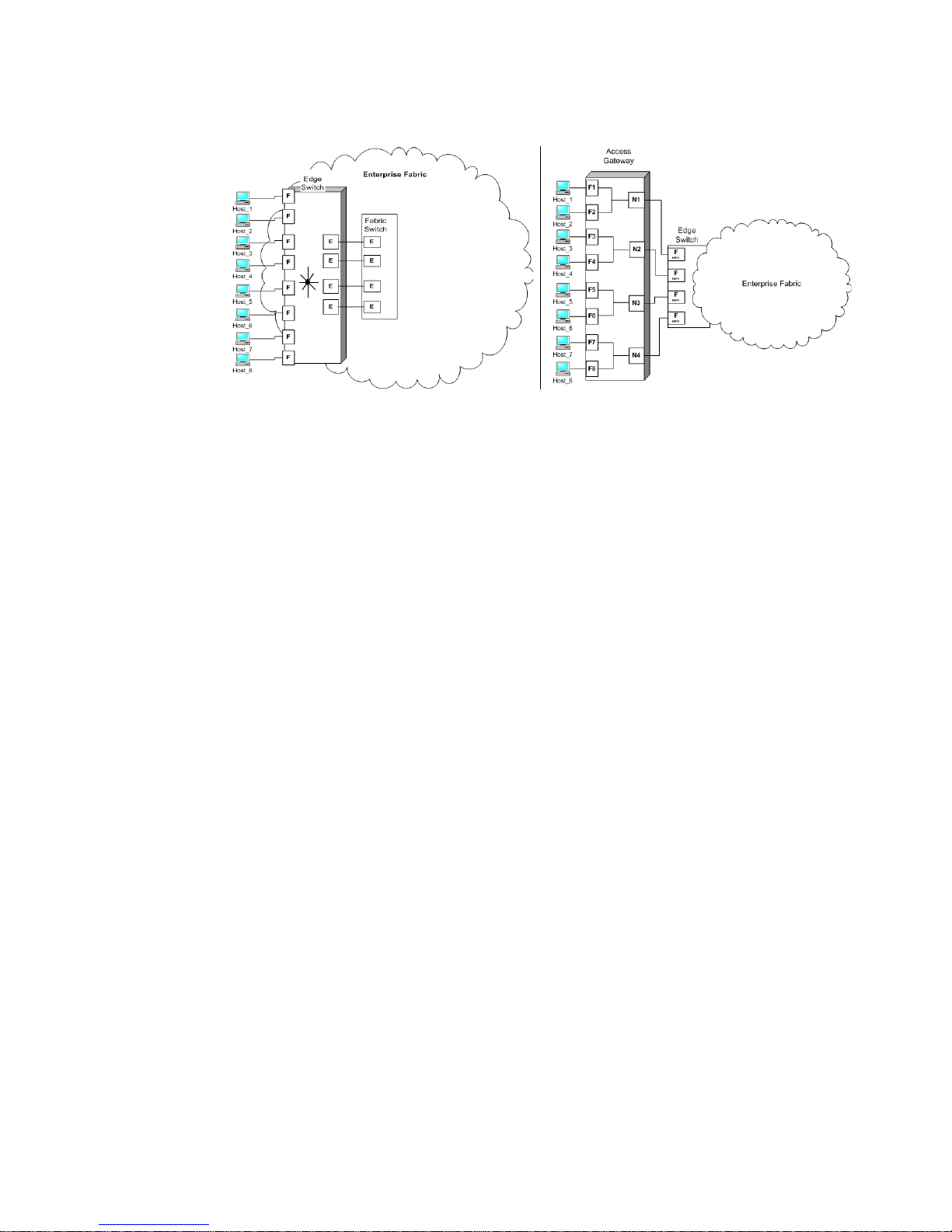
Figure 1 shows a comparison of a configuration that connects eight hosts to a fabric using AG to
the same configuration with Fabric OS switches in Native mode.
Switches in AG mode are logically transparent to the host and the fabric. You can increase the
number of hosts to have access to the fabric without increasing the number of switches. This
simplifies configuration and management in a large fabric by reducing the number of domain IDs
and ports.
Access Gateway Administrator’s Guide 1
53-1000605-02
Page 16
Brocade Access Gateway
1
FIGURE 1 Access Gateway and fabric switch comparison
The following points summarize the differences between a Fabric OS switch in Native mode and a
Fabric OS switch in AG mode:
• The Fabric OS switch in Native mode is a part of the fabric; it requires two to four times as
many physical ports, consumes fabric resources, and can connect to a Fabric OS fabric only.
• AG is outside the fabric; it reduces the number of switches in the fabric and the number of
required physical ports. You can connect AG to either a Fabric OS, M-EOS, or Cisco-based
fabric.
Fabric OS features in Access Gateway mode
When a switch is behaving as an Access Gateway, RBAC features in Fabric OS are available, but
Admin Domains, Advanced Performance Monitoring, direct connection to SAN target devices are
available, Fibre Channel Arbitrated Loop support, Fabric Manager, FICON, IP over FC, ISL trunking,
extended fabrics, management platform services, name services (SNS), port mirroring, SMI-S, and
zoning are not available. For more information on AG supported features, see “Access Gateway
trunking considerations” on page 23. You must have the role of securityadmin, admin, or user to
configure AG.
All security enforcement is done in the Enterprise fabric using the Advanced Device Security policy
(ADS), which secures virtual connections in the case where the physical connection to the SAN is
lost. When you enable the ADS policy, by default, every port is configured to allow all devices to log
in or be a part of the Access List. The Allow list restricts the number of devices that can log in to a
specified F_Port. Because all WWNs are a part of the Access List, you can identify which devices
are allowed to log in on a per F_Port basis by specifying the device’s port WWN(PWWN). Using the
ag
--adsset command, you can set the “Allow List” to All Access or No Access.
For example, the Allow List can include the N_Port WWN and the PWWNs of all the HBAs connected
to the F_Ports that are mapped an N_Port, which is connected to a switch in AG mode. If there is an
ADS policy violation, the AG connection is disabled and all of the N_Ports to which the F_Ports are
connected are also disabled. For information on how to specify which devices to include or exclude
at login, see “Setting which devices can log in if ADS policy is enabled” on page 9 or “Setting which
devices cannot log in if ADS policy is enabled” on page 10.
2 Access Gateway Administrator’s Guide
53-1000605-02
Page 17
Access Gateway port types
N_Port
F_Port
N_Port
F_Port
N_Port
F_Port
Hosts
Switch in AG mode
Edge Switch
Fabric
enabled
NPIV
N_Port
F_Port
E_Port
E_Port
N_Port
F_Port
Hosts
Switch in standard
Fabric Switch
E_Port
E_Port
Fabric
Access Gateway Ports
Fabric Switch Ports
default mode
Access Gateway differs from a typical fabric switch because it is not a switch; instead, it is a mode
that you enable on a switch using the ag command. After a switch is set in ag mode, it can connect
to the fabric using node ports (N_Ports). Typically fabric switches connect to the Enterprise fabric
using ISL (InterSwitch Link) ports, such as E_Ports.
Following are the Fibre Channel (FC) ports that AG uses:
• F_Port - fabric port that connects a host, HBA, or storage device to a switch in AG mode.
• N_Port - node port that connects a switch in AG mode to the F_Port of the fabric switch.
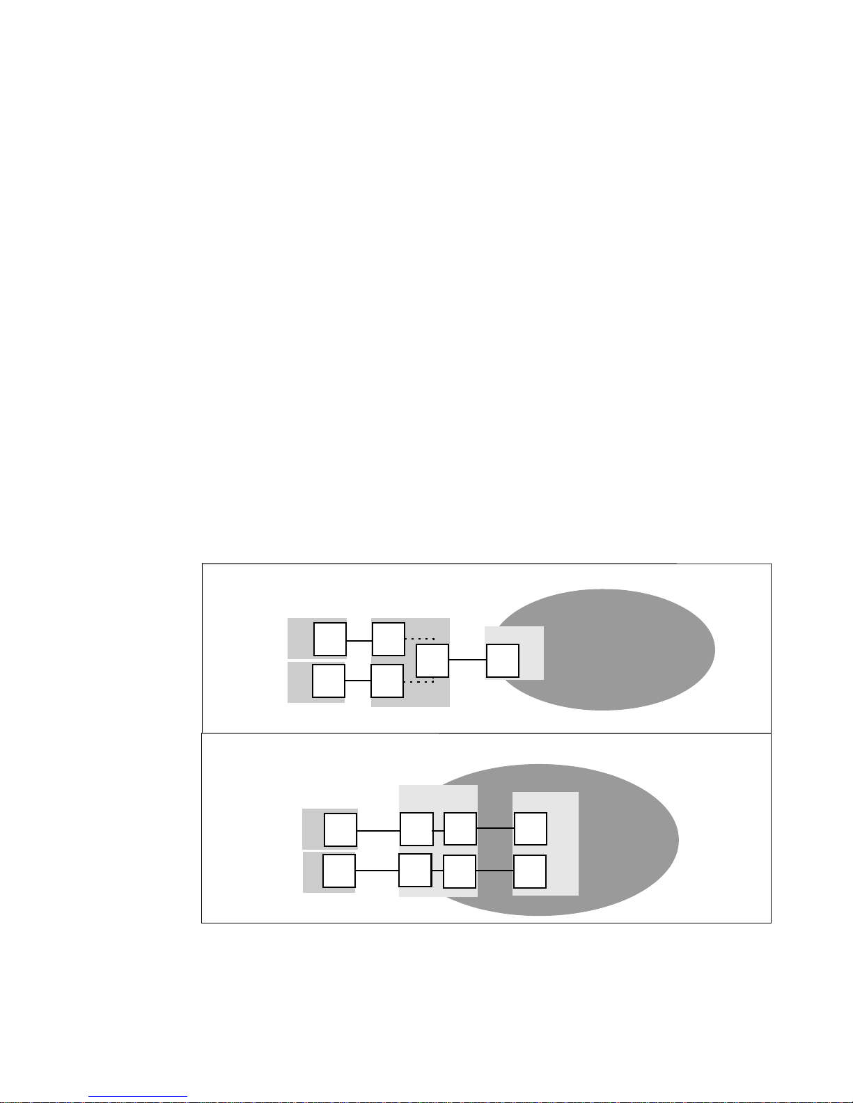
Comparison of Access Gateway ports to standard switch ports
Access Gateway multiplexes host connections to the fabric. It presents an F_Port to the host and an
N_Port to an edge fabric switch. Using N_Port ID virtualization (NPIV), AG allows multiple FC
initiators to access the SAN on the same physical port. This reduces the hardware requirements
and management overhead of hosts to the SAN connections.
A fabric switch presents F_Ports (or FL_Ports) and storage devices to the host and presents
E_Ports, VE_Ports, or EX_Ports to other switches in the fabric. A fabric switch consumes SAN
resources, such as domain IDs, and participates in fabric management and zoning distribution. A
fabric switch requires more physical ports than AG to connect the same number of hosts.
Access Gateway port types
1
Figure 2 shows a comparison of the types of ports a switch in AG mode uses to the type of ports
that a standard fabric switch uses.
FIGURE 2 Port usage comparison
Access Gateway Administrator’s Guide 3
53-1000605-02
Page 18
How Access Gateway maps ports
N_2
F_A2
Hosts
Access Gateway
Edge Switch
Fabric
(Switch_A)
enabled
NPIV
F_4
F_3
F_2
F_1
N_1
F_A1
enabled
NPIV
N_3
F_B1
enabled
NPIV
Host_1
Host_2
Host_3
Host_4
F_5
Host_5
F_6
Host_6
F_7
Host_7
F_8
Host_8
Edge Switch
(Switch_B)
N_4
F_B2
enabled
NPIV
1
Tab le 1 shows a comparison of port configurations with AG to a standard fabric switch.
TABLE 1 Port configurations
Port Type Access Gateway Fabric switch
F_Port Yes Connects hosts and targets to
Access Gateway.
N_Port Yes Connects Access Gateway to a fabric
switch.
E_Port NA ISL is not supported.
1. The switch is logically transparent to the fabric, therefore it does not participate in the SAN as a fabric switch.
How Access Gateway maps ports
Access Gateway uses mapping—that is, pre provisioned routes—to direct traffic from the hosts to
the fabric. When you first enable a switch to AG mode, by default, the F_Ports are mapped to a set
of predefined N_Ports. For the default F_Port-to-N_Port mapping, see Table 9 on page 51. If
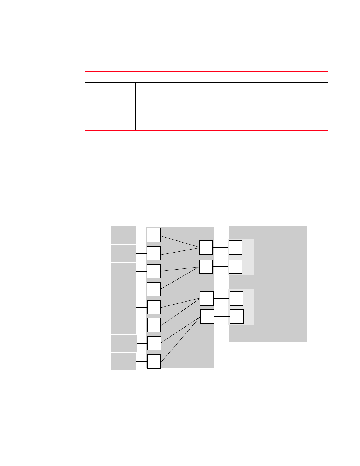
required, you can manually change the default mapping. Figure 3 shows a mapping with eight
F_Ports evenly mapped to four N_Ports on a switch in AG mode. The N_Ports connect to the same
fabric through different edge switches.
Yes Connects devices, such as hosts, HBAs,
and storage to the fabric.
NA N_Ports are not supported.
1
Yes Connects the switch to other switches to
form a fabric.
FIGURE 3 Example F_Port-to-N_Port mapping
4 Access Gateway Administrator’s Guide
53-1000605-02
Page 19

TABLE 2 Description of F_Port-to-N_Port mapping
Access Gateway Fabric
F_Port N_Port Edge switch F_Port
F_1, F_2 N_1 Switch_A F_A1
F_3, F_4 N_2 Switch_A F_A2
F_5, F_6 N_3 Switch_B F_B1
F_7, F_8 N_4 Switch_B F_B2
Upgrade and downgrade considerations
Downgrading to Fabric OS v6.0.0 or earlier is supported; however, you must first disable the switch
from AG mode. Note the following considerations when upgrading and downgrading from Fabric OS
v6.1.0 to Fabric OS v6.0.0 and earlier:
• Not allowed if any F_Port trunk is active.
• Trunking must be disabled before downgrading.
• When a switch is set in AG mode, if you downgrade to v6.0.0x, all preferred settings are
lost.
Upgrade and downgrade considerations
1
Considerations with policies enabled
Note the following upgrade and downgrade considerations when the Brocade policies are enabled.
Advance Device Security policy
If ADS is enabled, downgrading to v6.0 is allowed, however the ADS policy is not supported in
v6.0.0.
Automatic Port Configuration policy
If you upgrade from Fabric OS v6.0.x to Fabric OS v6.1.0, by default, the APC policy is disabled. If
the APC is enabled, you can downgrade from Fabric OS v6.1.0 to Fabric OS v6.0.0.
Port Grouping policy
If you upgrade from v6.0.0 to v6.1.0, then the PG policy is enabled with the default port group pg0
containing all the N_Ports. If the PG policy is enabled, you can downgrade from Fabric OS v6.1.0 to
Fabric OS v6.0.0.
Access Gateway Administrator’s Guide 5
53-1000605-02
Page 20

Upgrade and downgrade considerations
1
6 Access Gateway Administrator’s Guide
53-1000605-02
Page 21

Chapter
Enabling Policies on Switches in Access Gateway Mode
This chapter provides information and procedures for enabling policies on switches in Access
Gateway mode.
In this chapter
•Access Gateway policies . . . . . . . . . . . . . . . . . . . . . . . . . . . . . . . . . . . . . . . . . . 8
•Showing current policies . . . . . . . . . . . . . . . . . . . . . . . . . . . . . . . . . . . . . . . . . . 8
•Advance Device Security policy . . . . . . . . . . . . . . . . . . . . . . . . . . . . . . . . . . . . 8
•Enabling the Advance Device Security policy . . . . . . . . . . . . . . . . . . . . . . . . . 9
•Disabling the Advance Device Security policy . . . . . . . . . . . . . . . . . . . . . . . . . 9
•Setting which devices can log in if ADS policy is enabled . . . . . . . . . . . . . . . 9
•Setting which devices cannot log in if ADS policy is enabled. . . . . . . . . . . . 10
•Removing devices from the list of devices allowed at login . . . . . . . . . . . . . 10
•Adding new devices to the list of devices allowed at login . . . . . . . . . . . . . . 10
•Displaying the list of devices on the switch . . . . . . . . . . . . . . . . . . . . . . . . . . 11
•Automatic Port Configuration policy . . . . . . . . . . . . . . . . . . . . . . . . . . . . . . . . 11
•Enabling the Automatic Port Configuration policy. . . . . . . . . . . . . . . . . . . . . 12
•Disabling the Automatic Port Configuration policy . . . . . . . . . . . . . . . . . . . . 12
•Rebalancing F_Ports with APC policy enabled . . . . . . . . . . . . . . . . . . . . . . . 12
•Enabling the Failover policy . . . . . . . . . . . . . . . . . . . . . . . . . . . . . . . . . . . . . . 14
•Failover Policy . . . . . . . . . . . . . . . . . . . . . . . . . . . . . . . . . . . . . . . . . . . . . . . . . 13
•Enabling the Failover policy . . . . . . . . . . . . . . . . . . . . . . . . . . . . . . . . . . . . . . 14
•Disabling the Failover policy . . . . . . . . . . . . . . . . . . . . . . . . . . . . . . . . . . . . . . 15
•Failback policy . . . . . . . . . . . . . . . . . . . . . . . . . . . . . . . . . . . . . . . . . . . . . . . . . 15
•Enabling the Failback policy . . . . . . . . . . . . . . . . . . . . . . . . . . . . . . . . . . . . . . 16
•Cold Failover policy . . . . . . . . . . . . . . . . . . . . . . . . . . . . . . . . . . . . . . . . . . . . . 17
•Port Grouping policy . . . . . . . . . . . . . . . . . . . . . . . . . . . . . . . . . . . . . . . . . . . . 17
•Creating a port group . . . . . . . . . . . . . . . . . . . . . . . . . . . . . . . . . . . . . . . . . . . 19
•Adding an N_Port to a port group. . . . . . . . . . . . . . . . . . . . . . . . . . . . . . . . . . 20
•Deleting an N_Port from a port group . . . . . . . . . . . . . . . . . . . . . . . . . . . . . . 20
•Removing a port group . . . . . . . . . . . . . . . . . . . . . . . . . . . . . . . . . . . . . . . . . . 20
•Renaming a port group . . . . . . . . . . . . . . . . . . . . . . . . . . . . . . . . . . . . . . . . . . 21
•Disabling the Port Group policy . . . . . . . . . . . . . . . . . . . . . . . . . . . . . . . . . . . 21
•Access Gateway policy enforcement matrix. . . . . . . . . . . . . . . . . . . . . . . . . . 21
2
Access Gateway Administrator’s Guide 7
53-1000605-02
Page 22

Access Gateway policies
2
•Access Gateway trunking considerations . . . . . . . . . . . . . . . . . . . . . . . . . . . 23
•Trunk group creation . . . . . . . . . . . . . . . . . . . . . . . . . . . . . . . . . . . . . . . . . . . . 25
•Setting up F_Port trunking . . . . . . . . . . . . . . . . . . . . . . . . . . . . . . . . . . . . . . . 26
•Assigning a Trunk Area . . . . . . . . . . . . . . . . . . . . . . . . . . . . . . . . . . . . . . . . . . 26
•Enabling Access Gateway trunking. . . . . . . . . . . . . . . . . . . . . . . . . . . . . . . . . 28
•Enabling the DCC policy on trunk . . . . . . . . . . . . . . . . . . . . . . . . . . . . . . . . . . 27
•Disabling F_Port trunking . . . . . . . . . . . . . . . . . . . . . . . . . . . . . . . . . . . . . . . . 29
•F_Port Trunking monitoring. . . . . . . . . . . . . . . . . . . . . . . . . . . . . . . . . . . . . . . 30
Access Gateway policies
Brocade policy-based approach lets you restrict or filter traffic on standard Fabric OS switches and
switches in Access Gateway mode. You can enable the following policies on a switch in Access
Gateway mode:
• Advance Device Security policy (ADS)
• Automatic Port Configuration policy (APC)
• Port Grouping policy (PG)
Showing current policies
You can run the following command to see which policies are enabled or disabled on a switch.
1. Connect to the switch and log in as admin.
2. Enter the ag
switch:admin> ag --policyshow
Policy_Description Policy_Name State
-------------------------------------------------Port Grouping pg Enabled
Auto Port Configuration auto Disabled
Advanced Device Security ads Enabled
--policyshow command.
Advance Device Security policy
The Advance Device Security (ADS) policy is supported on AG F_Ports. Fabric OS v6.1.0 extends the
DCC policy to switches in AG mode to provide an additional level of security. It does this by
extending the DCC policy to the physical F_Ports and the NPIV logins on F_Ports. As more physical
servers become virtual, virtual servers can become vulnerable and security becomes an integral
part of server IO virtualization. This security policy is a mechanism that restricts fabric connectivity
to a set of devices that you can specify or allow to log in to the fabric connected through a switch in
AG mode. By default, the ADS policy is not enabled. After you set a switch in AG mode, you can
enable the ADS policy, and then specify which devices to allow at login on a per F_Port basis.
Security enforcement can also be done in the enterprise fabric; the DCC policy in the enterprise
fabric takes precedence over the ADS policy. When you enable the ADS policy, it applies to all the
ports on the switch. By default, all devices have access to the fabric on all ports.
8 Access Gateway Administrator’s Guide
53-1000605-02
Page 23

Enabling the Advance Device Security policy
NOTE
1. Connect to the switch and log in as admin.
Access Gateway policies
2
2. Enter the ag
switch:admin> ag --policyenable ads
The policy ADS is enabled
--policyenable ads command.
Disabling the Advance Device Security policy
1. Connect to the switch and log in as admin.
2. Enter the ag
switch:admin> ag --policydisable ads
The policy ADS is disabled
--policydisable ads command.
Setting which devices can log in if ADS policy is enabled
You can determine which devices are allowed to log in on a per F_Port basis by specifying the
device’s port WWN (PWWN). Use the ag --adsset command to determine which devices are
allowed to log in to a specified set of F_Ports. Lists must be enclosed in double quotation marks.
List members must be separated by semicolons. The maximum number of entries in the allowed
device list is twice the per port maximum log in count. Replace the WWN list with an asterisk (*) to
indicate all access on the specified F_Port list. Replace the F_Port list with an asterisk (*) to add
the specified WWNs to all the F_Ports' allow lists. A blank WWN list (““) indicates no access. The
ADS policy must be enabled for this command to succeed.
Use an asterisk enclosed in quotation marks,“*”, to set the Allow list to “All Access” to all F_Ports;
use a pair of double quotation marks ("") to set the Allow list to “No Access”.
Note the following characteristics of the Allow List:
• The maximum device entries allowed in the Allow List is twice the per port max login count
• Each port can be configured to “not allow any device” or “to allow all the devices” to log in
• If the ADS policy is enabled, by default, every port is configured to allow all devices to log in
• The same Allow List can be specified for more than one F_Port.
For example, to set the list of allowed devices for ports 1, 10, and 13 to all access:
1. Connect to the switch and log in as admin.
2. Enter the ag --adsset “1;10;13”“*” command.
switch:admin> ag–-adsset“1;10;13”“*”
WWN list set successfully as the Allow Lists of the F_Port[s]
Access Gateway Administrator’s Guide 9
53-1000605-02
Page 24

Access Gateway policies
2
Setting which devices cannot log in if ADS policy is enabled
For example, to set the list of allowed devices for ports 11 and 12 to no access:
1. Connect to the switch and log in as admin.
2. Enter the ag --adsset “11;12 ““ command.
switch:admin > ag –-adsset “11;12” “”
WWN list set successfully as the Allow Lists of the F_Port[s]
Removing devices from the list of devices allowed at login
Use the ag --adsdel command to delete the specified WWNs from the list of devices allowed to log
in to the specified F_Ports. Lists must be enclosed in double quotation marks. List members must
be separated by semicolons. Replace the F_Port list with an asterisk (*) to remove the specified
WWNs from all the F_Ports' allow lists. The ADS policy must be enabled for this command to
succeed.
For example, to remove two devices from the list of allowed devices for ports 3 and 9, use the
following syntax:
ag--adsdel "F_Port [;F_Port2;...]" "WWN [;WWN2;...]"
1. Connect to the switch and log in as admin.
2. Enter the ag --adsdel “3;9 ““ "22:03:08:00:88:35:a0:12;22:00:00:e0:8b:88:01:8b"
command.
switch:admin> ag --adsdel "3;9"
"22:03:08:00:88:35:a0:12;22:00:00:e0:8b:88:01:8b"
WWNs removed successfully from Allow Lists of the F_Port[s]Viewing F_Ports
allowed to login
Adding new devices to the list of devices allowed at login
Use the adsadd command to add the specified WWNs to the list of devices allowed to log in to the
specified F_Ports. Lists must be enclosed in double quotation marks. List members must be
separated by semicolons. Replace the F_Port list with an asterisk (*) to add the specified WWNs to
all the F_Ports' allow lists. The ADS policy must be enabled for this command to succeed.
For example, to add two new devices to the list of allowed devices for ports 3 and 9, use the
following syntax:
ag--adsadd "F_Port [;F_Port2;...]" "WWN [;WWN2;...]"
1. Connect to the switch and log in as admin.
2. Enter the ag --adsadd "3;9" "20:03:08:00:88:35:a0:12;21:00:00:e0:8b:88:01:8b" command.
switch:admin> ag --adsadd "3;9"
"20:03:08:00:88:35:a0:12;21:00:00:e0:8b:88:01:8b"
WWNs added successfully to Allow Lists of the F_Port[s]
10 Access Gateway Administrator’s Guide
53-1000605-02
Page 25

Access Gateway policies
ATTENTION
2
Displaying the list of devices on the switch
1. Connect to the switch and log in as admin.
2. Enter the ag --adsshow command.
switch:admin> ag --adsshow
F_Port WWNs Allowed
------------------------------------------------------------------------- 1 ALL ACCESS
3 20:03:08:00:88:35:a0:12
21:00:00:e0:8b:88:01:8b
9 20:03:08:00:88:35:a0:12
21:00:00:e0:8b:88:01:8b
10 ALL ACCESS
11 NO ACCESS
12 NO ACCESS
13 ALL ACCESS
--------------------------------------------------------------------------
Automatic Port Configuration policy
Automatic Port Configuration (APC) is an optional policy and is disabled by default. When APC is
enabled, the switch automatically discovers the port type. For example, when a switch in AG mode
is connected to a port, AG configures the port as an N_Port. If a host is connected to a port on
Access Gateway, then AG determines that it is connected and configures the port as an F_Port.
After all the port types are determined, dynamic mapping between F_Ports and N_Ports is created
and F_Ports are evenly distributed across all N_Ports. While the APC is enabled, you cannot
manually configure F_Port-to-N_Port mapping.
Enabling the APC policy is disruptive to F_Ports and N_Ports. You must disable the switch before you
enable the APC policy because when you enable the APC policy, existing F_Port-to-N_Port mappings
are deleted. Because the APC policy enforcement erases port mappings existing on the switch, it is
recommended to perform a configupload before enabling the APC policy. After you enable the APC
policy, the policy immediately takes effect; a reboot is not required. When you disable the APC policy,
the N_Port configuration and the F_Port-to-N_Port mapping revert back to the default factory
configuration for that platform.
The APC policy is mutually exclusive with the Port Grouping policy. When the APC policy is enabled
on a switch connected to multiple fabrics, no attempt is made by AG to restrict failover behavior
even if the N_Ports are connected to unrelated fabrics. Do not to use the APC policy when Access
Gateway is connected to multiple fabrics.
Access Gateway Administrator’s Guide 11
53-1000605-02
Page 26

Access Gateway policies
NOTE
2
Enabling the Automatic Port Configuration policy
1. Connect to the switch and log in as admin.
2. Ensure that the switch is disabled, enter the switchdisable command
3. Enter the ag --policyenable auto command to enable the APC policy.
switch:admin> ag --policyenable auto
All Port related Access Gateway configurations will be lost.
Please save the current configuration using configupload.
Do you want to continue? (yes, y, no, n): [no] y
4. Enter the configupload command to save the switch’s current configuration.
5. At the command prompt, type Y to enable the policy.
The switch is ready; a reboot is not required.
Disabling the Automatic Port Configuration policy
1. Connect and log in to the switch.
2. Enter the command ag --policydisable auto to disable the APC policy.
3. At the command prompt, type Y to disable the policy.
switch:admin> ag --policydisable auto
Default factory settings will be restored.
Default mappings will come into effect.
Please save the current configuration using configupload.
Do you want to continue? (yes, y, no, n): [no] y
Access Gateway configuration has been restored to factory default
4. Enter the switchenable command to enable the switch.
Rebalancing F_Ports with APC policy enabled
When the APC policy is enabled, there are no static mappings between F_Ports and N_Ports and no
F_Ports are tied to a specific N_Port. When an F_Port comes online after the initial mapping is
done, the F_Ports are automatically routed through one of the available N_Ports such that the
F_Ports are evenly balanced across all the available N_Ports. Similarly, if a new N_Port comes
online after the initial F_Port initialization, some of the F_Ports being routed through existing
N_Ports will fail over to the new N_Port, if rebalancing is needed.
Because of the disruption caused by the redistribution of F_Ports, it is recommended to add new
N_Ports to the module. For more information on adding N_Ports, see “Adding an N_Port to a port
group” on page 20.
12 Access Gateway Administrator’s Guide
53-1000605-02
Page 27

Access Gateway policies
NOTE
NOTE
2
Failover Policy
When a port is configured as an N_Port and if by default, the Failover policy is enabled, F_Ports are
not disabled if its N_Port goes off line. If you specify a Preferred Secondary N_Port for any of the
F_Ports, and if the N_Port goes offline, the F_Ports will fail over to the Preferred Secondary N_Port
and then re-enable. The specified Preferred Secondary N_Port must be online; otherwise, not the
F_Ports will become disabled.
Alternatively, if a Preferred Secondary N_Port is not set for any of F_Ports, the F_Ports will fail over
to other online N_Ports belonging to the same N_Port group, and then re-enable. The FLOGI and
FDISC requests are forwarded from F_Ports through the new N_Port. If multiple N_Ports are
available as candidates for failover, Access Gateway selects one or more N_Ports so that the
F_Ports are evenly balanced across all the N_Ports.
Failover of F_Ports to new a N_Port generates a RASLOG message.
The Failover policy allows hosts to automatically remap to an online N_Port if the primary N_Port
goes offline. The Failover policy is enabled (or enforced) during power-up. The Failover policy evenly
distributes the F_Ports that are mapped to an offline N_Port among all the online N_Ports. The
Failover policy is a parameter of each N_Port. By default, the Failover policy is enabled for all
N_Ports.
The following sequence describes how a failover event occurs:
• An N_Port goes offline.
• All F_Ports mapped to that N_Port are disabled.
• If the N_Port Failover policy is enabled, and a Preferred Secondary N_Port is specified for the
F_Port and that N_Port is online, the F_Port fails over to the respective Preferred Secondary
N_Port, and then re-enables.
The Preferred Secondary N_Port is defined per F_Port. For example, if two F_Ports are mapped
to a primary N_Port1, you can define a secondary N_Port for one of those F_Ports and not
define a secondary N_Port for the other F_Port. Typically, this is done by the server
administrator. You must determine whether you want to define a preferred secondary map for
each of the servers or just a subset of the servers.
• If the Preferred Secondary N_Port is not online, those F_Ports are disabled.
• If the Preferred Secondary N_Port is not set for any of the F_Ports, those F_Ports will fail over
to other available N_Ports belonging to the same N_Port group, and then re-enables.
• The host establishes a new connection with the fabric.
Example: Failover Policy
This example shows the failover behavior in a scenario where two fabric ports go offline, one after
the other. Note that this example assumes that no Preferred Secondary N_Port is set for any of the
F_Ports.
• First the edge switch F_A1 port goes offline, as shown in Figure 4 on page 14 Example 1 (left),
causing the corresponding Access Gateway N_1 port to be disabled.
The ports mapped to N_1 fail over; F_1 fails over to N_2 and F_2 fails over to N_3.
• Next the F_A2 port goes offline, as shown in Figure 4 on page 14 Example 2 (right), causing the
corresponding Access Gateway N_2 port to be disabled.
Access Gateway Administrator’s Guide 13
53-1000605-02
Page 28

Access Gateway policies
F_A2
Hosts
Access Gateway
Edge Switch
Fabric
(Switch_A)
enabled
NPIV
F_4
F_3
F_2
F_1
N_1
F_A1
enabled
NPIV
N_3
F_B1
enabled
NPIV
Host_1
Host_2
Host_3
Host_4
F_5
Host_5
F_6
Host_6
F_7
Host_7
F_8
Host_8
Edge Switch
(Switch_B)
N_4
F_B2
enabled
NPIV
N_2
Legend
Physical connection
Mapped online
Failover route online
Original mapped route
(offline)
Example 1
F_A2
Hosts
Access Gateway
Edge Switch
Fabric
(Switch_A)
enabled
NPIV
F_4
F_3
F_2
F_1
N_1
F_A1
enabled
NPIV
N_3
F_B1
enabled
NPIV
Host_1
Host_2
Host_3
Host_4
F_5
Host_5
F_6
Host_6
F_7
Host_7
F_8
Host_8
Edge Switch
(Switch_B)
N_4
F_B2
enabled
NPIV
Example 2
N_2
2
The ports mapped to N_2 (F_1, F_3, and F_4) fail over to N_3 and N_4. Note that the F_Ports
are evenly distributed to the remaining online N_Ports and that the F_2 port did not participate
in the failover event.
FIGURE 4 Example 1 and 2 Failover policy behavior
Enabling the Failover policy
1. Connect to the switch and log in as admin.
14 Access Gateway Administrator’s Guide
2. Enter the ag command with the
failover setting.
switch:admin> ag --failovershow 13
Failover on N_Port 13 is not supported
3. Enter the ag command with the --failoverenable <n_portnumber> operand to enable failover.
switch:admin> ag --failoverenable 13
Failover policy is enabled for port 13
--failovershow <n_portnumber> operand to display the
53-1000605-02
Page 29

Disabling the Failover policy
NOTE
1. Connect to the switch and log in as admin.
Access Gateway policies
2
2. Enter the ag command with the
failover setting.
switch:admin> ag --failovershow 13
Failover on N_Port 13 is supported
3. Enter the ag --failoverdisable <n_portnumber> operand to disable failover.
switch:admin> ag --failoverdisable 13
Failover policy is disabled for port 13
--failovershow <n_portnumber> operand to display the
Failback policy
The Failback policy automatically reroutes the F_Ports back to the primary mapped N_Ports as
those N_Ports come back online, if the Failback policy is enabled for the N_Port.
Only the originally mapped F_Ports fail back. In the case of multiple N_Port failures, only F_Ports
that were mapped to the recovered N_Port experience failback. The remaining F_Ports are not
redistributed among the online N_Ports during the failback. If the APC policy is enabled, by default,
the failback policy is disabled.
The Failback policy is an N_Port parameter. By default, the Failback policy is enabled.
The following sequence describes how a failback event occurs:
• When an N_Port comes back online, with the Failback policy enabled, the F_Ports that were
originally mapped to it are disabled.
• The F_Port is rerouted to the primary mapped N_Port, and then re-enabled.
• The host establishes a new connection with the fabric.
Example: Failback Policy
In Example 3, described in Figure 5 on page 16, the Access Gateway N_1 remains disabled
because the corresponding F_A1 port is offline. However, N_2 comes back online. See Figure 4 on
page 14 for the original failover scenario.
The ports F_1 and F_2 are mapped to N_1 and continue routing to N_3. Ports F_3 and F_4, which
were originally mapped to N_2, are disabled and rerouted to N_2, and then enabled.
Access Gateway Administrator’s Guide 15
53-1000605-02
Page 30

Access Gateway policies
F_A2
Hosts
Access Gateway
Edge Switch
Fabric
(Switch_A)
enabled
NPIV
F_4
F_3
F_2
F_1
N_1
F_A1
enabled
NPIV
N_3
F_B1
enabled
NPIV
Host_1
Host_2
Host_3
Host_4
F_5
Host_5
F_6
Host_6
F_7
Host_7
F_8
Host_8
Edge Switch
(Switch_B)
N_4
F_B2
enabled
NPIV
N_2
Legend
Physical connection
Mapped online
Failover route online
Original mapped route
(offline)
Example 3
2
FIGURE 5 Failback policy behavior
Enabling the Failback policy
1. Connect to the switch and log in as admin.
2. Enter the ag
setting.
switch:admin> ag --failbackshow 13
Failback on N_Port 13 is not supported
3. Enter the ag --failbackenable command with the n_portnumber operand to enable failover.
switch:admin> ag --failbackenable 13
Failback policy is enabled for port 13
Disabling the Failback policy
1. Connect to the switch and log in as admin.
2. Enter the ag
setting.
switch:admin> ag --failbackshow 13
Failback on N_Port 13 is supported
3. Enter the ag --failbackdisable command with the n_portnumber operand to disable failover.
switch:admin> ag --failbackdisable 13
Failback policy is disabled for port 13
--failbackshow command with the n_portnumber operand to display the failover
--failbackshow command with the n_portnumber operand to display the failback
16 Access Gateway Administrator’s Guide
53-1000605-02
Page 31

Access Gateway policies
NOTE
2
Cold Failover policy
All F_Ports for an N_Port that goes offline are failed over to other N_Ports. However, if the N_Port
fails to come online after the switch comes online, it triggers cold failover of its F_Ports. If any of
these F_Ports have a Preferred Secondary N_Port set, and if the Preferred Secondary N_Port is
online, those F_Ports fail over to the Preferred Secondary N_Port during cold failover. If the
Preferred Secondary N_Port is not online, those F_Ports are disabled. If the Preferred Secondary
N_Port is not set for any of these F_Ports, these F_Ports failover to any N_Ports on the switch so
that the F_Ports are evenly balanced across all the N_Ports belonging to the same N_Port group.
Access Gateway incorporates a number of Failover and Failback policies to ensure maximum up time
for the servers.
Port Grouping policy
When connecting a switch in AG mode to multiple fabrics or isolating a subset of servers from other
servers, you can group a number of servers and its corresponding fabric ports. You can do this by
enabling the Port Grouping policy (PG), which can only be performed on N_Ports. Port groups
cannot be overlapped. This means that an N_Port cannot belong to two different groups.
The Failover and Failback policies remain the same within each port group and the Preferred
Secondary N_Port can only specify the N_Ports from the same port group. This is why it is
recommended to form groups before defining the preferred secondary path. This behavior is only in
Fabric OS v6.0.0. When upgrading from Fabric OS v6.0.0 to Fabric OS v6.1.0, the PG policy that
was enforced in Fabric OS v6.0.0 continues to be enforced in Fabric OS v6.1.0 and the port groups
are retained.
For example, Figure 8 on page 19 shows an example of pg0. If N_Port1 and 2 are in pg0 and
F_Ports 1 and 2 are using N_Port1 and N_Port1 goes offline, then F_Ports1 and 2 are routed
through N_Port2 because N_Port2 is in the same port group, pg0.
Figure 6 shows that if you create port groups and when an N_Port goes offline, the F_Ports being
routed through that port will fail over to any of the N_Ports that are part of that port group and are
currently active. For example, if N_Port4 goes offline then F_Ports7 and 8 are routed through to
N_Port 3 as long as N_Port 3 is online because both N_Ports3 and 4 belong to the same port
group, PG2. If no active N_Ports are available, the F_Ports are disabled. The F_Ports belonging to a
port group do not failover to N_Ports belonging to another port group.
Access Gateway Administrator’s Guide 17
53-1000605-02
Page 32

Access Gateway policies
ATTENTION
2
FIGURE 6 Port grouping behavior
When a dual redundant fabric configuration is used, F_Ports connected to a switch in AG mode can
access the same target devices from both of the fabrics. In this case, you must group the N_Ports
connected to the redundant fabric into a single port group. It is recommended to have paths fail
over to the redundant fabric when the primary fabric goes down.
FIGURE 7 pg1 setup
If N_Ports are connected to unrelated fabrics are grouped together, N_Port failover within a port
group can cause the F_Ports to connect to a different fabric and the F_Ports may lose connectivity
to the targets they were connected to before the failover, thus causing I/O disruption as shown in
Figure 7.
18 Access Gateway Administrator’s Guide
53-1000605-02
Page 33

Access Gateway policies
NOTE
2
FIGURE 8 pg0 default setup
You can create new port groups and add N_Ports to those groups. However, all N_Ports that are not
part of any user-created port group are part of the default port group pg0.
Because port groups cannot be overlapped, if you specify an N_Port as a Preferred Secondary
N_Port and it already belongs to another port group, the Port Group creation fails.
If the PG policy is disabled while a switch in AG mode is online, all the user-defined port groups are
deleted, but the F_Port-to-N_Port mapping remain unchanged.
Creating a port group
1. Connect to the switch and log in as admin.
2. Enter the command ag --pgcreate with the <PG_ID> “<N_Port1;N_Port2;…> [-n <PG_Name>]
operands. For example, to create a port group “FirstFabric” that includes N_Ports 1 and 3:
switch:admin> ag --pgcreate 3 "1;3" -n FirstFabric1
Port Group 3 created successfully
3. Enter the command ag --pgshow to verify the port group was created.
switch:admin> ag --pgshow
Port Group ID Port Group Name
-----------------------------------0 None pg0
2 0;2 SecondFabric
3 1;3 FirstFabric
------------------------------------
Access Gateway Administrator’s Guide 19
53-1000605-02
Page 34

Access Gateway policies
2
Adding an N_Port to a port group
1. Connect to the switch and log in as admin.
2. Enter the command ag --pgadd with the <PG_ID> “<N_Port1;N_Port2;…> operands.
If you add more than one N_Port you must separate them with a semicolon.
switch:admin> ag --pgadd 3 14
N_Port[s] are added to the port group 3
3. Enter the command ag --pgshow to verify the N_Port was added to the specified port group.
switch:admin> ag --pgshow
PG_ID N_Ports PG_Name
----------------------------------------------------------------------------0 15 pg0
3 12;13;14 Test
-----------------------------------------------------------------------------
Deleting an N_Port from a port group
1. Connect to the switch and log in as admin.
2. Enter the command ag --pgdel with the <PG_ID> <N_Port1;N_Port2;…> operands.
switch:admin> ag --pgdel 3 13
N_Port[s] are added to the port group 3
3. Enter the command ag --pgshow to verify the N_Port was deleted from the specified port
group.
switch:admin> ag --pgshow
PG_ID N_Ports PG_Name
----------------------------------------------------------------------------0 13;15 pg0
3 12;14 Test
-----------------------------------------------------------------------------
Removing a port group
1. Connect to the switch and log in as admin.
2. Enter the command ag --pgremove with the <PG_ID> operands.
switch:admin> ag --pgremove 3
Port Group 3 has been removed successfully
3. Enter the command ag --pgshow to verify the port group has been deleted.
switch:admin> ag --pgshow
PG_ID N_Ports PG_Name
----------------------------------------------------------------------------0 12;13;14;15 pg0
-----------------------------------------------------------------------------
20 Access Gateway Administrator’s Guide
53-1000605-02
Page 35

Access Gateway policies
2
Renaming a port group
1. Connect to the switch and log in as admin.
2. Enter the command ag --pgrename with the <PG_ID> <newname> operands, for example, to
rename port group with pgid 2 to "MyEvenFabric":
switch:admin> ag --pgrename 2 MyEvenFabric
Port Group 2 has been renamed as MyEvenFabric successfully
3. Enter the command ag --pgshow to verify the port group has been renamed.
switch:admin> ag --pgshow
PG_ID N_Ports PG_Name
-------------------------------------0 None pg0
2 0;2 MyEvenFabric
3 1;3 FirstFabric
Disabling the Port Group policy
1. Connect to the switch and log in as admin.
2. Enter the command ag --policydisable with the pg operand.
switch:admin> ag --policydisable pg
3. Enter the command ag --pgshow to verify the Port Group policy is disabled.
switch:admin> ag --policyshow
AG Policy Policy Name State
---------------------------------------------------------Port Grouping pg Disabled
Auto Port Configuration auto Disabled
Advance Device Security ADS Disabled
----------------------------------------------------------
Access Gateway policy enforcement matrix
The following table shows which combinations of policies can co-exist with each other.
TABLE 3 Policy enforcement matrix
Policies Auto Port Configuration Port Grouping N_Port Trunking ADS Policy
Auto Port Configuration
N_Port Grouping
N_Port Trunking
ADS Policy
NA Mutually exclusive Can co-exist Can co-exist
Mutually exclusive N/A Can co-exist Can co-exist
Can co-exist Can coexist N/A Can co-exist
Can co-exist Can co-exist Can co-exist N/A
Access Gateway Administrator’s Guide 21
53-1000605-02
Page 36

Access Gateway N_Port trunking
NOTE
NOTE
2
Access Gateway N_Port trunking
On switches running in Access Gateway mode, the masterless trunking feature trunks N_Ports
because only the external port or the N_Port can connect to a switch in AG mode. After you map or
assign F_Ports to an N_Port, the N_Port distributes frames across a set of available path links on
the switch in AG mode to an adjacent edge switch. To use Access Gateway masterless trunking, all
trunking must be configured on the edge switch. Following are the advantages of Access Gateway
N_Port trunking:
• When one or more N_Ports in a trunk group goes offline, there is no change in the PID for the
F_Port(s) that were mapped to the N_Port(s) as long as at least one N_Port in the trunk group
is active. This provides for a transparent failover and failback within the trunk group.
• N_Port links are more efficient because of the trunking algorithm implemented in the
switching ASICs that distributes the I/O more evenly across the N_Ports.
• Trunk groups cannot span across multiple N_Port groups within a switch in AG mode.
• Multiple trunk groups are allowed within the same N_Port group.
On the edge switch, this feature is called F_Port trunking or masterless F_Port trunking.
Because you must configure the trunking on the edge switch, F_Port trunking, provides a Trunk
group between a switch (N_Port) in Access Gateway (AG) mode and Condor-based platforms. This
feature keeps F_Port(s) from becoming disabled in the case where they are mapped to an N_Port
on a switch in Access Gateway mode. With F_Port trunking, any link within a trunk can go off line or
become disabled, but the trunk remains fully functional and there are no re-configuration
requirements.
F_Port trunking prevents reassignments of the Port ID (also referred to as the Address Identifier as
described in Table 5 on page 25) when F_Ports go offline and it increases F_Port bandwidth.
Access Gateway N_Port trunking interoperates between Access Gateway (AG), 2 Gbps, 4 Gbps, and
8 Gbps-based platforms. This feature does not work on M-EOS or third party switches.
You must install the Brocade ISL license on the switch, which must be running Fabric OS 6.1.0 or
later. All switches that you connect to AG must be included in a port group; otherwise, switches
outside of a port group cannot connect to AG. For more information on Port Groups, see “Port
Grouping policy” on page 17.
If a switch already has an ISL Trunking license, no new licenses is required to use it on AG N_Port
masterless trunking; Also, after a trunking license is installed on a switch in AG mode and you
change the switch to standard mode, you can keep the same license.
To implement N_Port masterless trunking, you must first configure an F_Port Trunk group and
statically assign an Area_ID within the trunk group. Assigning a Trunk Area (TA) to a port or trunk
group enables F_Port masterless trunking on that port or trunk group. When a TA is assigned to a
port or trunk group, the ports will immediately acquire the TA as the area of its process IDs (PID).
And when a TA is removed from a port or trunk group, the ports reverts to the default area as its
PID.
22 Access Gateway Administrator’s Guide
53-1000605-02
Page 37

Access Gateway N_Port trunking
Access Gateway trunking considerations
TABLE 4 Access Gateway trunking considerations
Category Description
Area assignment You statically assign the area within the trunk group on the edge
switch. That group is the N_Port masterless trunk.
The static trunk area you assign must fall within the F_Port trunk
group starting from port 0 on a edge switch or blade.
The static trunk area you assign must be one of the port’s default
areas of the trunk group.
Authentication Authentication occurs only on the F_Port trunk master port and
only once per the entire trunk. This behavior is same as E_Port
trunk master authentication. Because only one port in the trunk
does FLOGI to the switch, and authentication follows FLOGI on
that port, only that port displays the authentication details when
you issue the portshow command.
Note: Switches in Access Gateway mode do not perform
authentication.
Management Server Registered Node ID (RNID), Link Incident Record Registration
(LIRR), and (QSA) Query Security Attributes ELS's are not
supported on F_Port trunks.
Trunk area The port must be disabled before assigning a Trunk Area on the
edge switch to the port or removing a Trunk Area from a trunk
group.
2
You cannot assign a Trunk Area to ports if the standby CP is
running a firmware version earlier than Fabric OS v6.1.0.
PWWN The entire Trunk Area trunk group share the same Port WWN
within the trunk group. The PWWN is the same across the F_Port
trunk that will have 0x2f or 0x25 as the first byte of the PWWN.
The TA is part of the PWWN in the format listed in Table 5 on
page 25.
Downgrade You can have trunking on, but you must disable the trunk ports
before performing a firmware downgrade.
Note: Removing a Trunk Area on ports running traffic is disruptive.
Use caution before assigning a Trunk Area if you need to
downgrade to a firmware earlier than Fabric OS v6.1.0.
Upgrade No limitations on upgrade to Fabric Os v6.1.0 if the F_Port is
present on switch. Upgrading is not disruptive.
HA Sync If you plug in a standby-CP with a firmware version earlier than
Fabric OS v6.1.0 and a Trunk Area is present on the switch, the CP
blades will become out of sync.
Port Types Only F_Port trunk ports are allowed on a Trunk Area port for Fabric
OS v6.1.0. All other port types that include F/FL/E/EX are
persistently disabled in Fabric OS v6.1.0.
Default Area Port X is a port that has its Default Area the same as its Trunk
Area. The only time you can remove port X from the trunk group is
if the entire trunk group has the Trunk Area disabled.
Access Gateway Administrator’s Guide 23
53-1000605-02
Page 38

Access Gateway N_Port trunking
2
TABLE 4 Access Gateway trunking considerations
Category Description
portCfgTrunkPort <port>, 0 portCfgTrunkPort <port>, 0 will fail if a Trunk Area is enabled on a
switchCfgTrunk 0 switchCfgTrunk 0 will fail if a port has TA enabled. All ports on a
Port Swap When you assign a Trunk Area to a trunk group, the Trunk Area
Trunk Master No more than one trunk master in a trunk group. The second
Fast Write When you assign a Trunk Area to a trunk group, the trunk group
FICON FICON is not supported on F_port trunk ports. However, FICON
FC8-48 and FC4-48C blades F_Port masterless trunking is supported on ports 16-43 on the
FC4-32 blade If an FC4-32 (Electron) blade has the Trunk Area enabled on ports
Trunking You must first enable Trunking on the port before the port can
PID format F_Port masterless trunking is only supported in CORE PID format.
Long Distance Long distance is not allowed on F_Port trunks, which means a
Port mirroring Port mirroring is not supported on Trunk Area ports or on the PID
configdownload If you issue the configdownload command for a port configuration
port. The port must be Trunk Area disabled first.
switch must be TA disabled first.
cannot be port swapped; if a port is swapped, then you cannot
assign a Trunk Area to that port.
trunk master will be persistently disabled with reason "Area has
been acquired”.
cannot have fast write enabled on those ports; if a port is fast
write enabled, the port cannot be assigned a Trunk Area.
can still run on ports that are not F_Port trunked within the same
switch.
FC8-48 blade. On the FC8-48 and FC4-48C blades F_Port
trunking supported only on ports 0 - 15.
16 - 31 and the blade is swapped with an FC4-48C and FC8-48
blade, the Trunk Area ports will be persistently disabled. You can
run the porttrunkarea command to assign a Trunk Area on those
ports.
have a Trunk Area assigned to it.
Trunk Area is not allowed on long distance ports; you cannot
enable long distance on ports that have a Trunk Area assigned to
them.
of an F_Port trunk port.
that is not compatible with F_Port trunking, and the port is Trunk
Area enabled, then the port will be persistently disabled.
ICL Port F_Port trunks are not allowed on ICL Ports. The porttrunkarea
AD You cannot create a Trunk Area on ports with different Admin
24 Access Gateway Administrator’s Guide
Note: Configurations that are not compatible with F_Port trunking
are long distance, port mirroring, non-CORE_PID, and fastwrite.
command does not allow it.
Domains. You cannot create a Trunk Area in AD255.
53-1000605-02
Page 39

Access Gateway N_Port trunking
TABLE 4 Access Gateway trunking considerations
Category Description
DCC Policy DCC policy enforcement for the F_Port trunk is based on the Trunk
Area; the FDISC requests to a trunk port is accepted only if the
WWN of the attached device is part of the DCC policy against the
TA. The PWWN of the FLOGI sent from the AG will be dynamic for
the F_Port trunk master. Because you do not know ahead of time
what PWWN AG will use, the PWWN of the FLOGI will not go
through DCC policy check on an F_Port trunk master. However, the
PWWN of the FDISC will continue to go through DCC policy check.
D.I. Zoning
(D,I) AD
(D, I) DCC and (PWWN, I) DCC
Creating a Trunk Area may remove the Index ("I") from the switch
to be grouped to the Trunk Area. All ports in a Trunk Area share
the same "I". This means that Domain,Index (D,I), which refer to
an "I", that might have been removed, will no longer be part of the
switch.
Note: Ensure to include AD, zoning and DCC when creating a
Tru n k Area.
You can remove the port from the Trunk Area to have the "I" back
into effect. D,I will behave as normal, but you may see the effects
of grouping ports into a single "I".
2
Also, D,I continues to work for Trunk Area groups. The "I" can be
used in D,I if the "I" was the "I" for the Trunk Area group.
Note: “I” refers to Index and D,I refers to Domain,Index.
Two masters Two masters is not supported in the same F_Port trunk group.
QoS Not currently supported..
The following table describes the PWWN format for F_Port and N_Port trunk ports.
TABLE 5 PWWN format for F_Port and N_Port trunk ports
NAA = 2 2f:xx:nn:nn:nn:nn:nn:nn
(1)
NAA = 2 25:xx:nn:nn:nn:nn:nn:nn
(1)
Port WWNs for:
switch’s Fx_Ports.
Port WWNs for:
switch's Fx_Ports
The valid range of xx is [0 - FF],
for maximum of 256.
The valid range of xx is [0 - FF],
for maximum of 256.
Trunk group creation
Por t trunking is enabled between two separate Fabric OS switches that support trunking and where
all the ports on each switch reside in the same quad and are running the same speed. Trunk
groups form when you connect two or more cables on one Fabric OS switch to another Fabric OS
switch with ports in the same port group or quad. A port group or a quad is a set of sequential
ports, for example ports 0-3. The Brocade 300 switch supports a trunk group with up to eight ports.
The trunking groups are based on the user port number, with contiguous eight ports as one group,
such as 0 – 7, 8- 15, 16-23 and up to the number of ports on the switch.
Access Gateway Administrator’s Guide 25
53-1000605-02
Page 40

Access Gateway N_Port trunking
2
Setting up F_Port trunking
F_Port trunking is enabled between two separate Fabric OS switches that support trunking and
where all the ports on each switch reside in the same quad and are running the same speed. Trunk
groups form when you connect two or more cables on one Fabric OS switch to another Fabric OS
switch with ports in the same port group or quad. A port group or a quad is a set of sequential
ports, for example ports 0-3 in the figure shown below. The Brocade 300 platform supports a trunk
group with up to eight ports. The trunking groups are based on the user port number, with
contiguous eight ports as one group, such as 0 – 7, 8- 15, 16-23 and up to the number of ports on
the switch.
1. Connect to the switch and log in as admin.
2. Ensure that both modules (edge switch and the switch running in AG mode) have the trunking
licenses enabled.
3. Ensure that the ports have trunking enabled by issuing the portcfgshow command. If Trunking
is not enabled, issue the portcfgtrunkport <port>, 1 command.
4. Ensure that ports will become the same speed within the trunk.
5. Ensure that edge switch F_Port trunk ports are connected within the asic supported trunk
group on AG switch.
6. Ensure that both modules are running the same Fabric OS versions.
7. Configure the trunk on the edge switch by assigning the Trunk Area (TA) using the “Ass igning a
Trunk Area” procedure.
8. Enable F_Port trunking.
Assigning a Trunk Area
You must enable trunking on all ports to be included in a Trunk Area before you can create a Trunk
Area. Use the portCfgTrunkPort or switchCfgTrunk command to enable trunking on a port or on all
ports of a switch.
Issue the porttrunkarea command to assign a static TA on a port or port trunk group, to remove a
TA from a port or group of ports in a trunk, and to display masterless trunking information.
You can remove specified ports from a TA using the porttrunkarea --disable command; however
this command does not unassign a TA if its previously assigned Area_ID is the same address
identifier (Area_ID) of the TA unless all the ports in the trunk group are specified to be unassigned.
For more information on the porttrunkarea command, enter help porttrunkarea or see the Fabric
OS Command Reference. F_Port trunking will not support shared area ports 16 - 47 on the Brocade
FC8-48 and FC4-48C blades.
26 Access Gateway Administrator’s Guide
53-1000605-02
Page 41

Access Gateway N_Port trunking
The following table shows an example of the Address Identifier.
TABLE 6 Address identifier
23 22 21 20 19 18 17 16 15 14 13 12 11 10 9 8 7 6 5 4 3 2 1 0
Domain ID Area_ID Port ID
Address Identifier
1. Connect to the switch and log in as admin.
2. Disable the ports to be included in the TA.
3. Enable TA for ports 13 and 14 on slot 10 with port index of 125:
switch:admin> porttrunkarea --enable 10/13-14 -index 125
Trunk index 125 enabled for ports 10/13 and 10/14
4. Show the TA port configuration (ports still disabled):
switch:admin> porttrunkarea --show enabled
Slot Port Type State Master TI DI
------------------------------------------10 13 -- -- -- 125 125
10 14 -- -- -- 125 126
-------------------------------------------
2
5. Enable ports 13 and 14:
switch:admin> portenable 10/13
switch:admin> portenable 10/14
6. Show the TA port configuration after enabling the ports:
switch:admin> porttrunkarea --show enabled
Slot Port Type State Master TI DI
------------------------------------------10 13 F-port Master 10/13 125 125
10 14 F-port Slave 10/13 125 126
Enabling the DCC policy on trunk
1. After you assign a Trunk Area, the porttrunkarea CLI checks whether there are any active DCC
policies on the port with the index TA, and then issues a warning to add all the device WWNs to
the existing DCC policy with index as TA.
All DCC policies that refer to an Index that no longer exist will not be in effect.
2. Add the WWN of all the devices to the DCC policy against the TA.
3. Issue the secpolicyactivate command to activate the DCC policy.
You must enable the TA before issuing the secpolicyactivate command in order for security to
enforce the DCC policy on the trunk ports.
4. Turn on the trunk ports.
Trunk ports should be turned on after issuing the secpolicyactivate command to prevent the
ports from becoming disabled in the case where there is a DCC security policy violation.
Access Gateway Administrator’s Guide 27
53-1000605-02
Page 42

Access Gateway N_Port trunking
2
Configuration management for trunk areas
Ports from different ADs are not allowed to join the same Trunk Area group. The porttrunkarea
command prevents the different AD's from joining the TA group.
When you assign a TA, the ports within the TA group will have the same Index. The Index that was
assigned to the ports is no longer part of the switch. Any Domain,Index (D,I) AD that was assumed
to be part of the domain may no longer exist for that domain because it was removed from the
switch.
Example: How Trunk Area assignment affects the port Domain,Index
If you have AD1: 3,7; 3,8; 4,13; 4,14 and AD2: 3,9; 3,10, and then create a TA with Index 8 with
ports that have index 7, 8, 9, and 10. Then index 7, 9, and 10 are no longer with domain 3. This
means that AD2 does not have access to any ports because index 9 and 10 no longer exist on
domain 3. This also means that AD1 no longer has 3,7in effect because Index 7 no longer exists for
domain 3. AD1's 3,8, which is the TA group, can still be seen by AD1 along with 4,13 and 4,14.
A port within a TA can be removed, but this adds the Index back to the switch. For example, the
same AD1 and AD2 with TA 8 holds true. If you remove port 7 from the TA, it adds Index 7 back to
the switch. That means AD1's 3,7 can be seen by AD1 along with 3,8; 4,13 and 4,14.
Enabling Access Gateway trunking
1. Disable ports 36 - 39 by executing portdisable port for each port to be included in the TA.
2. Enable Trunk Area for ports 36 - 39 with area number 37:
switch:admin> porttrunkarea --enable 36-39 -index 37
Trunk area 37 enabled for ports 36, 37, 38 and 39.
3. Re-enable ports 36-39 by executing portenable port for each port in the TA.
4. Show switch/port information:
switch:admin> switchshow
switchName: SPIRIT_B4_01
switchType: 66.1
switchState: Online
switchMode: Native
switchRole: Principal
switchDomain: 2
switchId: fffc02
switchWwn: 10:00:00:05:1e:41:22:80
zoning: OFF
switchBeacon: OFF
FC Router: ON
FC Router BB Fabric ID: 100
Area Port Media Speed State Proto
=====================================
0 0 -- N8 No_Module
1 1 -- N8 No_Module
2 2 -- N8 No_Module
3 3 -- N8 No_Module
4 4 -- N8 No_Module
5 5 -- N8 No_Module
6 6 -- N8 No_Module
28 Access Gateway Administrator’s Guide
53-1000605-02
Page 43

Access Gateway N_Port trunking
7 7 -- N8 No_Module
8 8 id N4 Online F-Port 10:00:00:00:00:01:00:00
9 9 -- N8 No_Module
10 10 -- N8 No_Module
11 11 -- N8 No_Module
12 12 -- N8 No_Module
13 13 -- N8 No_Module
14 14 -- N8 No_Module
15 15 -- N8 No_Module
16 16 -- N8 No_Module
17 17 -- N8 No_Module
18 18 -- N8 No_Module
19 19 -- N8 No_Module
20 20 -- N8 No_Module
21 21 -- N8 No_Module
22 22 -- N8 No_Module
23 23 -- N8 No_Module
24 24 -- N8 No_Module
25 25 -- N8 No_Module
26 26 -- N8 No_Module
27 27 -- N8 No_Module
28 28 -- N8 No_Module
29 29 -- N8 No_Module
30 30 -- N8 No_Module
31 31 -- N8 No_Module
32 32 id N4 No_Light
33 33 id N4 No_Light
34 34 id N4 No_Light
35 35 id N4 No_Light
36 36 id N4 Online F-Port 20:14:00:05:1e:41:4b:4d
37 37 id N4 Online F-Port 20:15:00:05:1e:41:4b:4d
38 38 id N4 Online F-Port 20:16:00:05:1e:41:4b:4d
39 39 id N4 Online F-Port 2 NPIV public
2
5. Display TA enabled port configuration:
switch:admin> porttrunkarea --show enabled
Port Type State Master TA DA
------------------------------------36 -- -- -- 37 36
37 -- -- -- 37 37
38 -- -- -- 37 38
39 -- -- -- 37 39
Disabling F_Port trunking
1. Connect to the switch and log in as admin.
2. Enter the porttrunkarea --disable
switch:admin> porttrunkarea --disable 36-39
ERROR: port 36 has to be disabled
Disable each port prior to removing ports from the TA. Then reissue the command:
switch:admin> porttrunkarea --disable 36-39
Trunk area 37 disabled for ports 36, 37, 38 and 39.
command.
Access Gateway Administrator’s Guide 29
53-1000605-02
Page 44

Access Gateway N_Port trunking
2
F_Port Trunking monitoring
For F_Port masterless trunking, you must install Filter, EE or TT monitors on the F_Port trunk port.
Whenever the master port changes, it is required to move the monitor to the new master port. For
example, if a master port goes down, a new master is selected from the remaining slave ports. APM
must delete the monitor from the old master and install the monitor on new master port. If you
attempt to add a monitor to a slave port, it is automatically added to the master port.
30 Access Gateway Administrator’s Guide
53-1000605-02
Page 45

Chapter
Connecting Devices Using Access Gateway
This chapter describes how to connect multiple devices to a switch in Access Gateway (AG) mode,
discusses edge switch compatibility, port requirements, NPIV HBA, and interoperability. Access
Gateway supports Direct Target Attach, which allows you to directly attach a target device to a
switch in AG mode if the AG switch is connected to an external fabric. AG does not support daisy
chaining when two AG devices are connected to each other. Switches in AG mode can connect to
other types of fabrics on edge switches with the following firmware versions:
• M-EOSc v9.6.2 or later and M-EOSn v9.6
• Cisco v3.0(1) or later, v3.1(1) or later, and v3.2 (1) or later.
• Only FCP initiator ports can be connected to a switch in AG mode as F_Ports. FCP target ports
are supported if a switch in AG mode is connected to an external switch. Loop devices and
FICON channels/control unit connectivity are not supported.
• When a switch is in AG mode, it can be connected to NPIV-enabled HBAs, or F_Ports that are
NPIV-aware. Access Gateway supports NPIV industry standards per FC-LS-2 v1.4.
In this chapter
3
•Configuring the fabric and edge switch . . . . . . . . . . . . . . . . . . . . . . . . . . . . . 32
•Verifying the switch mode . . . . . . . . . . . . . . . . . . . . . . . . . . . . . . . . . . . . . . . . 32
•Setting the Fabric OS switch to Native Mode . . . . . . . . . . . . . . . . . . . . . . . . 33
•Enabling NPIV on the M-EOS switch. . . . . . . . . . . . . . . . . . . . . . . . . . . . . . . . 33
•Connectivity to Cisco Fabrics . . . . . . . . . . . . . . . . . . . . . . . . . . . . . . . . . . . . . 34
•Enabling NPIV on a Cisco switch . . . . . . . . . . . . . . . . . . . . . . . . . . . . . . . . . . 34
•Workaround for QLogic-based devices. . . . . . . . . . . . . . . . . . . . . . . . . . . . . . 35
•Editing Company ID List if no FC target devices on switch . . . . . . . . . . . . . . 35
•Editing Company ID List if no FC target devices on switch . . . . . . . . . . . . . . 35
•Adding or deleting an OUI from the Company ID List . . . . . . . . . . . . . . . . . . 36
•Enabling Flat FCID mode if no FC target devices on switch . . . . . . . . . . . . . 37
•Editing Company ID list if target devices on switch . . . . . . . . . . . . . . . . . . . . 37
•Enabling Flat FCID mode if no FC target devices on switch . . . . . . . . . . . . . 37
•Access Gateway mode. . . . . . . . . . . . . . . . . . . . . . . . . . . . . . . . . . . . . . . . . . . 38
•Enabling Access Gateway mode. . . . . . . . . . . . . . . . . . . . . . . . . . . . . . . . . . . 38
•Port States . . . . . . . . . . . . . . . . . . . . . . . . . . . . . . . . . . . . . . . . . . . . . . . . . . . . 39
•Disabling Access Gateway mode . . . . . . . . . . . . . . . . . . . . . . . . . . . . . . . . . . 40
•Reverting to a previous configuration . . . . . . . . . . . . . . . . . . . . . . . . . . . . . . 41
•Re-joining switches to a fabric . . . . . . . . . . . . . . . . . . . . . . . . . . . . . . . . . . . . 41
Access Gateway Administrator’s Guide 31
53-1000605-02
Page 46

Configuring the fabric and edge switch
NOTE
3
Configuring the fabric and edge switch
To connect hosts to the fabric using Access Gateway, configure the fabric using the following
parameters. These parameters apply to Fabric OS, M- EOS, and Cisco-based fabrics:
• Install and configure the switch as described in the switch’s Hardware Reference Manual
before performing these procedures.
• Verify that the interop mode parameter is set to 0, Brocade Native mode, or the switch mode is
in Native mode.
• Configure the F_Ports on the edge switch to which Access Gateway is connected as follows:
• Enable NPIV.
• Disable long distance mode.
• Allow multiple logins. The recommended fabric login setting is the maximum allowed per
port and per switch.
• Use only WWN zoning throughout the fabric. Access Gateway does not support domain ID and
other types of zoning schemes.
• Include the Access Gateway WWN or the port WWN of the N_Ports, also include the HBA WWNs
that will be connected to AG F_Ports to the ACL list in ACL policies.
• Allow inband queries for forwarded fabric management requests from the hosts. Add the
Access Gateway switch WWN to the access list if inband queries are restricted.
Befoe connecting Access Gateway to a Fabric OS fabric, disable the Fabric OS Management Server
Platform Service.
Verifying the switch mode
1. Connect to the switch and log in as admin.
2. Enter the switchShow command to display the current switch configuration.
The following example shows a switch in the Fabric OS Native mode where switchMode
displays as Native.
switch:admin> switchshow
switchName: switch
switchType: 43.2
switchState: Online
switchMode: Native
switchRole: Principal
switchDomain: 1
switchId: fffc01
switchWwn: 10:00:00:05:1e:03:4b:e7
zoning: OFF
switchBeacon: OFF
Area Port Media Speed State Proto
=====================================
0 0 -- N4 No_Module
1 1 cu N4 Online F-Port 50:06:0b:00:00:3c:b7:32
2 2 cu N4 Online F-Port 10:00:00:00:c9:35:43:f5
3 3 cu AN No_Sync
4 4 cu AN No_Sync Disabled (Persistent)
32 Access Gateway Administrator’s Guide
53-1000605-02
Page 47

Configuring the fabric and edge switch
5 5 cu N4 Online F-Port 50:06:0b:00:00:3c:b4:3e
6 6 cu N4 Online F-Port 10:00:00:00:c9:35:43:f3
7 7 cu AN No_Sync Disabled (Persistent)
8 8 cu AN No_Sync
9 9 cu AN No_Sync Disabled (Persistent)
10 10 cu AN No_Sync Disabled (Persistent)
11 11 cu AN No_Sync Disabled (Persistent)
12 12 cu AN No_Sync Disabled (Persistent)
13 13 cu AN No_Sync Disabled (Persistent)
14 14 cu AN No_Sync Disabled (Persistent)
15 15 cu AN No_Sync Disabled (Persistent)
16 16 cu AN No_Sync Disabled (Persistent)
17 17 -- N4 No_Module
18 18 -- N4 No_Module
19 19 -- N4 No_Module
20 20 -- N4 No_Module
21 21 id N4 Online E-Port segmented,(zone conflict)(Trunk
master)
22 22 id N4 Online E-Port (Trunk port, master is Port 21 )
23 23 id N4 Online E-Port (Trunk port, master is Port 21 )
3
See Tab le 8 on page 39 for a description of the port state.
If the switch is in Native mode, you can enable AG mode; otherwise, set the switch to Native mode,
and then reboot the switch.
Setting the Fabric OS switch to Native Mode
1. Connect to the switch and log in as admin.
2. Enter the switchDisable command to disable the switch.
switch:admin> switchdisable
3. Save the switch configuration using the configUpload command.
a. Verify that the FTP service is running on the host computer.
b. Enter the configUpload command.
The command becomes interactive and you are prompted for the required information.
4. Enter the configure command and verify that interop mode is set to 0.
Enabling NPIV on the M-EOS switch
1. Connect to the switch and log in as admin on the M-EOS switch.
2. Enable the MS services by entering the following command:
config OpenSysMs setState
3. Enable NPIV functionality on the edge fabric ports so that multiple logins are allowed for each
port. Enter the following command on the M-EOS switch to enable NPIV on the specified ports.
config NPIV
Your M-EOS switch is now ready to connect.
Access Gateway Administrator’s Guide 33
53-1000605-02
Page 48

Connectivity to Cisco Fabrics
3
Connectivity to Cisco Fabrics
When connecting a switch in Access Gateway mode to a Cisco fabric where certain QLogic-based
devices are present behind the switch in AG mode, some QLogic FC ASIC-based Host Bus Adapters
(HBA)s are not compatible with the routing mechanism used by switches in AG mode.
In this case, you must configure the Cisco switch using the Cisco provided procedures to ensure
interoperability with Access Gateway.
If you are using Emulex HBAs or any other HBAs that are not based on QLogic FC ASIC technology,
ensure that N_Port ID Virtualization (NPIV) is enabled on the Cisco switch and that the switch is
running SAN-OS 3.0 (1) or SAN-OS 3.1 (1) or later. By default, NPIV is enabled per switch and not
per port.
Access Gateway routing requirements with Cisco fabrics
The routing mechanism that switches in AG mode and the workaround from Cisco to enable Cisco
MDS switches to interoperate with certain QLogic-based devices behind the AG switch is based on
the Cisco Company ID list.
Expanding the 8-bit ALPA routing in AG to 16-bit routing, which uses both the Area and the ALPA
fields, allows AG to handle PIDs with lower 8 bits. In ALPA routing mode, Cisco switches assign PIDs
to NPIV devices that differ in the lower 16 bits and assign PIDs for NPIV logins in the format of
ddXXXX. Fabric OS switches assigns PIDs in the format of ddaaXX. You can configure these
switches to route frames to a destination port based on the lower 16 bits in the PID.
Because switches in AG mode use the lower 8 bits of the FCID (that is, the ALPA/Port_ID field) to
route the frames between its F_Ports (connected to servers) and N_Ports (connected to the fabric)
Access Gateway cannot accept:
• Two FCIDs with the same lower 8 bits on the same N_Port (for example, 0xaabb02 and
0xccdd02)
• A "00" in the ALPA/Port_ID field of the FCID, which is returned for F_Ports logins (that is, server
HBA logins behind AG, also known as FDISC logins. If either of these two situations is detected,
the switch in AG mode persistently disables the server ports with the reason code "Duplicate
ALPA detected."
Enabling NPIV on a Cisco switch
1. Log in as admin on the Cisco MDS switch.
2. Enter the show version command to determine that you are using the correct SAN-OS version
and to see if NPIV is enabled on the switch.
3. Enter the following commands to enable NPIV:
conf t
enable npiv
4. Press Ctrl-Z to exit.
5. Enter the following commands to save the MDS switch connection:
copy run start
Your Cisco switch is now ready to connect to a switch in Access Gateway mode.
34 Access Gateway Administrator’s Guide
53-1000605-02
Page 49

Connectivity to Cisco Fabrics
NOTE
3
Workaround for QLogic-based devices
If there are QLogic-based devices behind a switch in AG mode, you must use the Cisco provided
procedures to connect to a Fabric OS switch in AG mode to a Cisco fabric. Cisco software maintains
a list of QLogic-based HBAs. Each HBA is identified by its company ID (also know as Organizational
Unit Identifier, or OUI) used in the PWWN during a fabric log in. You can modify the Cisco Company
ID entries using the CLI.
You must set the fcinterop FC ID allocation scheme to auto and use the company ID list and
persistent FC ID configuration to manipulate the FC ID device allocation.
Tab le 7 shows the Cisco Company ID list, which shows the OUI ID as the three middle bytes of the
World Wide Name (WWN). This OUI ID format is used for initiator devices.
TABLE 7 OUI IDs that require special treatment
OUI ID
00:E0:8B 00:02:6B
00:09:6B 00:06:2B WWN: 00:00:11:22:33:00:00:00
00:11:25 00:14:5E OUI
00:50:8B 00:A0:B8
00:60:B0 00:D0:60
00:90:A5 00:E0:69
00:50:2E 00:D0:B2
For detailed documentation on the FCID allocation for HBAs, go to:
http://www.cisco.com/en/US/docs/storage/san_switches/mds9000/sw/rel_2_x/san-os/configu
ration/guide/adv.html#wp1127676
Editing Company ID List if no FC target devices on switch
You can connect a Cisco MDS switch to a switch in AG mode if there are no FC target devices, such
as storage arrays on the Cisco switch. You can do this by editing the Company ID List or by placing
the Cisco switch FCID allocation mode into FLAT mode.
1. Connect to the switch and log in as admin on the Cisco MDS switch.
2. From the Company ID List, delete the OUI IDs of all the HBAs that are connected through the
switch in AG mode.
3. Delete the OUI IDs if and only if they are in the Company ID List.
4. Enter the following commands to determine the OUIs in the Company ID List:
switch#_show fcid-allocation area
FCID area allocation company id info:
00:50:2E
00:50:8B
00:60:B0
00:E0:79
00:0D:60 +
00:09:6B + <- User added entry
<- Default entry
<- User added entry
Access Gateway Administrator’s Guide 35
53-1000605-02
Page 50

Connectivity to Cisco Fabrics
3
Adding or deleting an OUI from the Company ID List
The following example shows how to add or delete an OUI (0x112233) from the Company ID List.
1. Enter the following command:
2. Enter the following command to add the OUI ID 0x112233 to list:
3. Enter the following command to delete the OUI ID 0x445566 from list:
4. Enter the following command to display the list:
5. Press Ctrl-Z to exit.
00:E0:8B * <- Explicitly deleted entry (from the original default list)
Total company ids 6
+ - Additional user configured company ids
* -Explicitly deleted company ids from default list.
config t
fcid-allocation area company-id 0x112233
no fcid-allocation area company-id 0x445566
do show fcid-allocation area
6. Issue the following command to save the MDS switch configuration.
copy run start
Ensure that the OUI IDs of the attached target devices are listed in the updated Company ID List.
After you update the list, you are ready to connect the Access Gateway device. If any of the AG
server ports (F_Ports) report that the port is disabled with reason code “Duplicate ALPA Detected,”
then use the follow considerations:
• Ensure that the debug FLOGI mode is not enabled; Cisco does not support NPIV when FLOGI
debug is set. Run the show debug flogi command to verify that the FLOGI mode is not enabled.
If the FLOGI mode is enabled, you must disable it using the following FLOGI debug commands:
config t
no flogi debug
Press Ctrl-Z to exit
copy run start Saves MDS switch configuration
• By default, if this is a new or an existing VSAN to use with the switch in Access Gateway mode,
the default policy for access is "deny." Either set it to "permit" or zone the devices for access.
• Access Gateway is compatible with Cisco VSAN, Dynamic Port VSAN (DVPM), and Inter-VSAN
Routing (IVR) features; however, you may need to use the AG Port Grouping policy to take full
advantage of these MDS features. For more information on the Port Grouping policy, see the
“Port Grouping policy” on page 17.
36 Access Gateway Administrator’s Guide
53-1000605-02
Page 51

Connectivity to Cisco Fabrics
NOTE
NOTE
3
Enabling Flat FCID mode if no FC target devices on switch
1. Alternatively, you can place the Cisco switch FCID allocation mode into FLAT mode by entering
the following commands:
config t
fcinterop fcid-allocation flat
2. Enter the following command to enable VSAN mode:
vsan database
3. Enter the following two commands to enable the Flat FCID mode:
vsan <vsan#> suspend
no vsan <vsan#> suspend
4. Press Ctrl-Z to exit.
5. Enter the following command to save the MDS switch configuration:
copy run start
If there are any device(s) in the VSAN that you suspend, it takes that device offline until you
unsuspend that VSAN.
Editing Company ID list if target devices on switch
If there are target devices on the switch, you must add the OUI of all the target devices present on
the switch to the Company ID list, and then delete the OUI IDs of all the HBAs that are connected
through the switch in Access Gateway mode from the Company ID list. You must remove the OUI IDs
if and only if they are in the Company ID list. Use the following commands to determine if the OUIs
in the Company ID list:
switch#_show fcid-allocation area
FCID area allocation company id info:
00:50:2E
00:50:8B
00:60:B0
00:E0:79
00:0D:60 +
00:09:6B + <- User -added entry
00:E0:8B * <- Explicitly deleted entry (from the original default list)
Total company ids 6
+ - Additional user configured company ids
* -Explicitly deleted company ids from default list.
You can also use the Persistent FCID field in the Cisco GUI tool to manually assign the FCIDs to
QLogic-based devices behind the Access Gateway module. If you use the method, ensure that
proper FCIDs are assigned, which have a different Area field from the target devices connected to
the same MDS switch. See “Access Gateway routing requirements with Cisco fabrics” on page 34 to
ensure that the switch meets the AG routing requirements.
<- Default entry
<- User -added entry
Access Gateway Administrator’s Guide 37
53-1000605-02
Page 52

Access Gateway mode
NOTE
3
Access Gateway mode
Before enabling a switch to AG mode, you must save the switch configuration because after you
enable AG mode, some fabric information is erased, such as the zone and security databases. For
information on backing up and restoring the configuration file, refer to the Fabric OS
Administrator’s Guide.
Enabling AG mode is disruptive; the switch is disabled and rebooted. You must verify that the switch
is set to Native mode or interopmode 0. Run the switchshow command to verify the switch mode. If
the switch mode is anything other than 0, you must run the interopmode 0 command to set the
switch to Native mode. For more information on setting switches to Native mode, see “Setting the
Fabric OS switch to Native Mode” on page 33. For more information on ag commands, refer to the
Fabric OS Command Reference.
If you are setting the Brocade 300 and 200E switches to AG modes, you must enable all ports
using POD licensing before enabling Access Gateway mode.
The maximum number of AGs that can be connected to an edge switch is 30. The maximum number
of devices that can be connected to a Fabric OS switch through AG depends on the maximum
number of local devices that are supported by Fabric OS.
Enabling Access Gateway mode
Ensure that no zoning or AD transaction buffers are active. If any transaction buffer is active,
enabling AG mode will fail with the error, “Failed to clear Zoning/Admin Domain configuration”.
1. Enter the ag
switch:admin> ag --modeenable
The switch automatically reboots and comes back online in AG mode using a factory default
F_Port to N_Port mapping. For more information on AG default F_Port to N_Port mapping, see
Tab le 9 on page 51.
2. Enter the ag
switch:admin> ag --modeshow
Access Gateway mode is enabled.
3. Enter the ag --mapshow command without any options to display all the mapped ports.
The ag
those N_Ports are not connected.
switch:admin> ag --mapshow
N_Port Configured_F_Ports Current_F_Ports Failover Failback PG_ID PG_Name
---------------------------------------------------------------------------- 0 4;5;6 4;5;6 1 0 2 SecondFabric
1 7;8;9 7;8;9 0 1 0 pg0
2 10;11 10;11 1 0 2 SecondFabric
3 12;13 12;13 0 1 0 pg0
-----------------------------------------------------------------------------
--modeenable command.
--modeshow command to verify that AG mode is enabled.
--mapshow command shows all the N_Ports (with the portcfgnport value of 1) even if
38 Access Gateway Administrator’s Guide
53-1000605-02
Page 53

Access Gateway mode
4. Enter the switchShow command without any options to display the status of all ports.
switch:admin> switchshow
switchName: switch
switchType: 43.2
switchState: Online
switchMode: Access Gateway Mode
switchWwn: 10:00:00:05:1e:03:4b:e7
switchBeacon: OFF
Area Port Media Speed State Proto
=====================================
0 0 -- N4 No_Module
1 1 cu N4 Online F-Port 50:06:0b:00:00:3c:b7:32 0x5a0101
2 2 cu N4 Online F-Port 10:00:00:00:c9:35:43:f5 0x5a0003
3 3 cu N4 Online F-Port 50:06:0b:00:00:3c:b6:1e 0x5a0102
4 4 cu N4 Online F-Port 10:00:00:00:c9:35:43:9b 0x5a0002
5 5 cu N4 Online F-Port 50:06:0b:00:00:3c:b4:3e 0x5a0201
6 6 cu N4 Online F-Port 10:00:00:00:c9:35:43:f3 0x5a0202
7 7 cu AN No_Sync Disabled (Persistent)
8 8 cu N4 Online F-Port 10:00:00:00:c9:35:43:a1 0x5a0001
9 9 cu AN No_Sync Disabled (Persistent)
10 10 cu AN No_Sync Disabled (Persistent)
11 11 cu AN No_Sync Disabled (Persistent)
12 12 cu AN No_Sync Disabled (Persistent)
13 13 cu AN No_Sync Disabled (Persistent)
14 14 cu AN No_Sync Disabled (Persistent)
15 15 cu AN No_Sync Disabled (Persistent)
16 16 cu AN No_Sync Disabled (Persistent)
17 17 -- N4 No_Module
18 18 -- N4 No_Module
19 19 id N4 No_Light
20 20 -- N4 No_Module
21 21 id N4 Online N-Port 10:00:00:05:1e:35:10:1e 0x5a0200
22 22 id N4 Online N-Port 10:00:00:05:1e:35:10:1e 0x5a0100
23 23 id N4 Online N-Port 10:00:00:05:1e:35:10:1e 0x5a0000
3
Port States
The following table describes the possible port states.
TABLE 8 Port state description
State Description
No _Card No interface card present
No _Module No module (GBIC or other) present
Mod_Val Module validation in process
Mod_Inv Invalid module
No_Light The module is not receiving light
No_Sync Receiving light but out of sync
In_Sync Receiving light and in sync
Laser_Flt Module is signaling a laser fault
Port_Flt Port marked faulty
Access Gateway Administrator’s Guide 39
53-1000605-02
Page 54

Access Gateway mode
NOTE
NOTE
3
TABLE 8 Port state description
State Description
Diag_Flt Port failed diagnostics
Lock_Ref locking to the reference signal
Testing running diagnostics
Offline Connection not established (only for virtual ports)
Online The port is up and running
Disabling Access Gateway mode
Before you disable a switch in AG mode, you should always back up the current configuration.
Disabling AG mode clears the F_Port-to-N_Port mapping.
Disabling AG mode is disruptive; the switch is disabled and rebooted. After AG mode is disabled,
the switch starts in Fabric OS Native mode. The switch will segment from the fabric upon reboot. To
re-join the switch to the core fabric, refer to “Re-joining switches to a fabric” on page 41.
For additional information on reconfiguring a switch and joining it to a fabric, see the Fabric OS
Administrator’s Guide.
1. Connect to the switch and log in as admin.
2. Enter the ag
switch:admin> ag --modeshow
Access Gateway mode is enabled
--modeshow command to verify that the switch is in AG mode.
3. Enter the switchDisable command to disable the switch.
switch:admin> switchdisable
To save the Access Gateway configuration, use the configUpload command before proceeding
with the next step.
4. Enter the ag command with the
switch:admin> ag --modedisable
--modedisable operand to disable AG mode.
The switch automatically reboots and comes back online using the fabric switch configuration;
the AG parameters, such as F_Port-to-N_Port mapping, and the failover and failback policies
are automatically removed.
5. Enter the ag
switch:admin> ag --modeshow
Access Gateway mode is NOT enabled
--modeshow command to verify that AG mode is disabled.
Use the configDownload command to restore a previous fabric configuration.
40 Access Gateway Administrator’s Guide
53-1000605-02
Page 55

Re-joining switches to a fabric
After a switch reboots and AG mode is disabled, the Default zone is set to no access. Therefore, the
switch does not immediately join the fabric to which it is connected. Use one of the following
methods to re-join a switch to the fabric:
• If you saved a Fabric OS configuration before enabling AG mode, download the configuration
using the configDownload command.
• If you want to re-join the switch to the fabric using the fabric configuration, use the following
procedure:
1. Connect to the switch and log in as admin.
2. Enter the switchDisable command to disable the switch.
Re-joining switches to a fabric
3
3. Enter the defZone
4. Enter the cfgSave command to commit the defzone changes.
5. Enter the switchEnable command to enable the switch and allow it to merge with the fabric.
The switch automatically re-joins the fabric.
--allAccess command to allow the switch to merge with the fabric.
Reverting to a previous configuration
1. Connect to the switch and log in as admin.
2. Enter the switchDisable command to disable the switch.
3. Enter the configDownload command to revert to the previous configuration.
4. Enter the switchEnable command to bring the switch back online.
The switch automatically joins the fabric.
Access Gateway Administrator’s Guide 41
53-1000605-02
Page 56

Re-joining switches to a fabric
3
42 Access Gateway Administrator’s Guide
53-1000605-02
Page 57

Chapter
Configuring Ports in Access Gateway mode
This chapter explains how to configure ports in Access Gateway mode and how to implement
Access Gateway masterless trunking.
In this chapter
•Port Initialization in Access Gateway mode . . . . . . . . . . . . . . . . . . . . . . . . . . 43
•N_Ports. . . . . . . . . . . . . . . . . . . . . . . . . . . . . . . . . . . . . . . . . . . . . . . . . . . . . . . 44
•Unlocking N_Ports . . . . . . . . . . . . . . . . . . . . . . . . . . . . . . . . . . . . . . . . . . . . . . 45
•Displaying N_Port configurations . . . . . . . . . . . . . . . . . . . . . . . . . . . . . . . . . . 46
•Verifying port mapping and status . . . . . . . . . . . . . . . . . . . . . . . . . . . . . . . . . 46
•Displaying N_Port mapping. . . . . . . . . . . . . . . . . . . . . . . . . . . . . . . . . . . . . . . 47
•Displaying port status . . . . . . . . . . . . . . . . . . . . . . . . . . . . . . . . . . . . . . . . . . . 47
•Port configurations . . . . . . . . . . . . . . . . . . . . . . . . . . . . . . . . . . . . . . . . . . . . . 48
•Adding F_Ports to an N_Port. . . . . . . . . . . . . . . . . . . . . . . . . . . . . . . . . . . . . . 48
•Removing F_Ports from an N_Port. . . . . . . . . . . . . . . . . . . . . . . . . . . . . . . . . 49
•Adding a preferred secondary N_Port . . . . . . . . . . . . . . . . . . . . . . . . . . . . . . 50
•Deleting F_Ports from a preferred secondary N_Port. . . . . . . . . . . . . . . . . . 50
4
Port Initialization in Access Gateway mode
To ensure that all hosts are brought online when a switch in Access Gateway mode starts up, the
ports are initialized in the following manner:
1. When you enable a switch to AG mode, N_Ports are initialized only if they belong to the default
factory configuration of the switch. During N_Port initialization all the F_Ports are disabled
(kept offline).
The ports are enabled or disabled as follows:
• Enabled (online) if the port receives a fabric login event and is connected to an F_Port of
an edge switch that supports NPIV (N_Port ID virtualization).
• Disabled (offline) if the port is not connected to a fabric or is connected to a fabric port
that does not support NPIV.
2. All F_Ports mapped to online N_Ports are enabled.
3. F_Ports mapped to an offline N_Port with the failover policy enabled fail over to an online
N_Port.
Access Gateway Administrator’s Guide 43
53-1000605-02
Page 58

4
a
b
c
d
e
N_Ports
4. The host logs into the fabric as follows:
a. The host sends a FLOGI (fabric login) request.
b. Access Gateway converts the FLOGI request into an FDISC request to the fabric with the
same parameters as the host.
c. The fabric processes the request and sends an FDISC response.
d. Access Gateway converts the FDISC Accept link service reply (ACC) response to the host as
an FLOGI ACC using the same parameters as the fabric.
e. The host receives the response from the fabric.
Figure 9 shows Access Gateway logically transparent to the host and the fabric after ports
are initialized.
N_Ports
FIGURE 9 Initialized ports in Access Gateway
You can expand your fabric by configuring the F_Ports to connect to the fabric as N_Ports, which
increases the number of device ports you can connect to a single fabric port. You can connect AG to
more than one fabric.
When AG is connected to at least one edge switch in the fabric, Fibre Channel ports operate as
either a target or as an initiator. Fibre Channel ports target por ts can also connect to AG as F_Ports.
The following combinations are possible with initiators and targets:
• All F_Ports connect to the FCP initiator port.
• All F_Ports connect to the FCP target port.
• Some F_Ports connect to the FCP initiator port and some connected to FCP target port.
• Targets and hosts that are connected to the same AG are not supported.
The AG port connected to the Enterprise fabric must be configured as an N_Port using the
portcfgnport mode command. By default, on embedded switches, only the internal ports of Access
Gateway are configured as F_Ports. All external ports are configured (locked) as N_Ports. For more
information on which ports are mapped by default, see Table 9 on page 51. The internal ports
connect hosts in the bladed server and external ports connect to the fabric.
44 Access Gateway Administrator’s Guide
53-1000605-02
Page 59

N_Ports
NOTE
NOTE
The enabled N_Port will automatically come online if it is connected to an Enterprise fabric switch
that supports NPIV. NPIV capability should be enabled on the ports connected to the Access
Gateway. Use the portcfgnpivport command to enable NPIV capability on the specific port. By
default, NPIV is enabled on 8 Gbps switches.
A switch in Access Gateway mode must have at least one port configured as an N_Port.
Therefore, the maximum number of F_Ports that can be mapped to an N_Port is the number of
ports on the switch minus one.
Figure 10 shows a host connected to an embedded switch’s external F_Port when Access Gateway
is enabled. The configured F_Port is mapped to an N_Port.
4
FIGURE 10 Example of adding an external F_Port (F9) on an embedded switch
Unlocking N_Ports
Unlocking the N_Port configuration automatically changes the port to an F_Port. When you unlock
an N_Port, the F_Ports are automatically unmapped and disabled.
1. Connect to the switch and log in as admin.
2. Enter the portcfgnport command.
The portcfgnport command only works when the Port Grouping policy is enabled.
switch:admin> portcfgnport
Ports 0 1 2 3 4 5 6 7 8 9 10 11 12 13 14 15
--------------------+--+--+--+--+--+--+--+--+--+--+--+--+--+--+--+--
Access Gateway Administrator’s Guide 45
53-1000605-02
Page 60

4
N_Ports
Locked N_Port .. .. .. .. .. .. .. .. .. .. ON ON ON ON ON ON
3. Enter the portcfgnport command with <portnumber> 0 operand to unlock N_Port mode.
switch:admin> portcfgnport 10 0
Alternatively, to lock a port in N_Port mode, enter the portcfgnport <portnumber> 1 command.
switch:admin> portcfgnport 10 1
By default, on embedded switches, all external ports are configured as N_Port lock mode when you
enable Access Gateway. Access Gateway connects only FCP initiators and targets to the fabric. It
does not support other types of ports, such as ISL (interswitch link) ports.
The port types on a fabric switch are not locked. Fabric OS Native mode dynamically assigns the
port type based on the connected device: F_Ports and FL_Ports for hosts, HBAs, and storage
devices; and E_Ports, EX_Ports, and VE_Ports for connections to other switches.
Displaying N_Port configurations
1. Connect to the switch and log in as admin.
2. Enter the portcfgnport command.
switch:admin> portcfgnport
Ports 0 1 2 3 4 5 6 7 8 9 10 11 12 13 14 15
--------------------+--+--+--+--+--+--+--+--+--+--+--+--+--+--+--+--
Locked N_Port .. .. .. .. .. .. .. .. .. .. ON ON ON ON ON ON
Verifying port mapping and status
You can display the port mappings and status of the host connections to the fabric on Access
Gateway using the ag
information on the ag command.
1. Connect to the switch and log in as admin.
2. Enter the ag
switch:admin> ag --mapshow
N_Port Configured_F_Ports Current_F_Ports Failover Failback PG_ID PG_Name
---------------------------------------------------------------------------- 0 4;5;6 4;5;6 1 0 2 SecondFabric
1 7;8;9 7;8;9 0 1 0 pg0
2 10;11 10;11 1 0 2 SecondFabric
3 12;13 12;13 0 1 0 pg0
-----------------------------------------------------------------------------
Use the following parameters:
N_Port The numbers of ports locked in N_Port mode.
Configured F_Ports The F_Ports that are mapped to the corresponding N_Port.
--mapshow command. See the Fabric OS Command Reference for more
--mapshow command.
46 Access Gateway Administrator’s Guide
53-1000605-02
Page 61

N_Ports
Current F_Ports Shows the F_Ports that are currently connected to the fabric on
the corresponding N_Port.
In the case of failover, the current F_Ports and configured
F_Ports differ.
Failover and Failback Indicates whether the N_Port policy is enabled (1) or disabled
(0).
PG_ID and PG_Name Indicates whether the Port Grouping policy is enabled (1) or
disabled (0).
Displaying N_Port mapping
1. Connect to the switch and log in as admin.
4
2. Enter the ag
--mapshow command and specify the port number.
The N_Port failover and failback policies and the mapped F_Ports displays.
switch:admin> ag --mapshow
N_Port Configured_F_Ports Current_F_Ports Failover Failback PG_ID PG_Name
--------------------------------------------------------------------------- 0 4;6 4;6 1 0 2 SecondFabric
1 7;8;9 7;8;9 0 1 0 pg0
2 5;10;11 5;10;11 1 0 2 SecondFabric
3 12;13 12;13 0 1 0 pg0
Displaying port status
1. Connect to the switch and log in as admin.
2. Enter the switchshow command without any operands.
switch:admin> switchshow
switchName: switch
switchType: 43.2
switchState: Online
switchMode: Access Gateway Mode
switchWwn: 10:00:00:05:1e:03:4b:e7
switchBeacon: OFF
Area Port Media Speed State Proto
=====================================
0 0 -- N4 No_Module
1 1 cu N4 Online F-Port 50:06:0b:00:00:3c:b7:32 0x5a0101
2 2 cu N4 Online F-Port 10:00:00:00:c9:35:43:f5 0x5a0003
3 3 cu N4 Online F-Port 50:06:0b:00:00:3c:b6:1e 0x5a0102
4 4 cu N4 Online F-Port 10:00:00:00:c9:35:43:9b 0x5a0002
5 5 cu N4 Online F-Port 50:06:0b:00:00:3c:b4:3e 0x5a0201
6 6 cu N4 Online F-Port 10:00:00:00:c9:35:43:f3 0x5a0202
7 7 cu AN No_Sync Disabled (Persistent)
8 8 cu N4 Online F-Port 10:00:00:00:c9:35:43:a1 0x5a0001
9 9 cu AN No_Sync Disabled (Persistent)
10 10 cu AN No_Sync Disabled (Persistent)
11 11 cu AN No_Sync Disabled (Persistent)
12 12 cu AN No_Sync Disabled (Persistent)
13 13 cu AN No_Sync Disabled (Persistent)
14 14 cu AN No_Sync Disabled (Persistent)
15 15 cu AN No_Sync Disabled (Persistent)
Access Gateway Administrator’s Guide 47
53-1000605-02
Page 62

Port configurations
NOTE
NOTE
4
16 16 cu AN No_Sync Disabled (Persistent)
17 17 -- N4 No_Module
18 18 -- N4 No_Module
19 19 id N4 No_Light
20 20 -- N4 No_Module
21 21 id N4 Online N-Port 10:00:00:05:1e:35:10:1e 0x5a0200
22 22 id N4 Online N-Port 10:00:00:05:1e:35:10:1e 0x5a0100
23 23 id N4 Online N-Port 10:00:00:05:1e:35:10:1e 0x5a0000
For a description of the port state, see Table 8 on page 39.
Port configurations
The following mapping updates and adding and removing of ports are only applicable to the Port
Grouping policy.
Adding F_Ports to an N_Port
When you update the mapping, only the F_Ports added or removed are affected. Adding an F_Port
to an N_Port routes that traffic to and from the fabric through the specified N_Port. When you
enable the failover policy and if the N_Port goes offline or fails, the F_Port automatically routes to
another N_Port, which is connected to the same fabric.
You can assign an F_Port to only one primary N_Port at a time. If the F_Port is already assigned to
an N_Port, you must remove it from the N_Port before you can add it. Use the following procedure
to add an F_Port to an N_Port.
For bladed servers, the HBA connects to the internal ports. Internal ports are F_Ports. By default,
only the external ports are configured as N_Ports.
1. Connect to the switch and log in as admin.
2. Enter the ag command with the
--mapdel <n_portnumber> <F_Port1;...;F_Port2> operand to
remove the F_Port from the N_Port. The f_portlist can contain multiple F_Port numbers
separated by semicolons, for example “17;18”.
switch:admin> ag --mapdel 10 6
F-Port to N-Port mapping has been updated successfully
3. Enter the switchshow command to verify that the F_Port is free (unassigned).
Unassigned F_Port status is Disabled (No mapping for F_Port). See port 6 in the following
example.
switch:admin> switchshow
switchName: fsw534_4016
switchType: 45.0
switchState: Online
switchMode: Access Gateway Mode
switchWwn: 10:00:00:05:1e:02:1d:b0
switchBeacon: OFF
Area Port Media Speed State Proto
48 Access Gateway Administrator’s Guide
53-1000605-02
Page 63

Port configurations
=====================================
0 0 cu AN No_Sync
1 1 cu AN No_Sync Disabled (N-Port Offline for F-Port)
2 2 cu AN No_Sync Disabled (N-Port Offline for F-Port)
3 3 cu AN No_Sync Disabled (N-Port Offline for F-Port)
4 4 cu AN No_Sync Disabled (N-Port Offline for F-Port)
5 5 cu AN No_Sync Disabled (N-Port Offline for F-Port)
6 6 cu AN No_Sync Disabled (No mapping for F-Port)
7 7 cu AN No_Sync
8 8 cu AN No_Sync
9 9 cu AN No_Sync
10 10 -- N4 No_Module
11 11 -- N4 No_Module
12 12 -- N4 No_Module
13 13 id N4 Online N-Port 10:00:00:05:1e:35:10:1e 0x5a0a00
14 14 id N4 Online N-Port 10:00:00:05:1e:35:10:1e 0x5a0900
15 15 id N4 Online N-Port 10:00:00:05:1e:35:10:1e 0x5a0800
4
4. Enter the ag command with the --mapadd <n_portnumber> “<f_port1;f_port2;...> operand to
add the list of F_Ports to the N_Port.
The f_portlist can contain multiple F_Port numbers separated by semicolons, for example
“17;18”.
switch:admin> ag --mapadd 13 "6;7"
F-Port to N-Port mapping has been updated successfully
5. Enter the ag --mapshow command with the n_portnumber operand to display the list of
mapped F_Ports. Verify that the added F_Ports appear in the list.
switch:admin> ag --mapshow 13
N_Port : 13
Failover(1=enabled/0=disabled) : 1
Failback(1=enabled/0=disabled) : 1
Current F_Ports : None
Configured F_Ports : 6;7
PG_ID : 0
PG_Name : pg0
Removing F_Ports from an N_Port
Removing F_Ports from an N_Port unassigns the F_Port. The F_Port status changes to Disabled.
(No mapping for F_Port).
1. Connect to the switch and log in as admin.
2. Enter the ag
remove the list of F_Ports from the N_Port.
switch:admin> ag --mapdel 13 “5;6”
F-Port to N-Port mapping has been updated successfully
3. Enter the ag --mapshow command with the n_portnumber operand to display a list of
mapped F_Ports. Verify that the F_Ports you removed are not in the list.
switch:admin> ag --mapshow 13
--mapdel command with the <n_portnumber> <f_port1;f_port2;...> operands to
N_Port : 13
Access Gateway Administrator’s Guide 49
53-1000605-02
Page 64

Port configurations
4
Failover(1=enabled/0=disabled) : 1
Failback(1=enabled/0=disabled) : 1
Current F_Ports : None
Configured F_Ports : 7
PG_ID : 0
PG_Name : pg0
Adding a preferred secondary N_Port
Preferred mapping is optional. Adding a preferred N_Port provides an alternate N_Port for F_Ports
to fail over to. The F_Ports must have a primary N_Port mapping before a secondary N_Port can be
configured.
You add the F_Ports to a preferred secondary N_Port using the prefset command, which sets the
preferred N_Port for one or more F_Ports. You can delete the F_Ports from the preferred N_Port
using the prefdel command. This following procedure shows adding F_Ports 3 and 9 to preferred
secondary N_Port 4.
1. Connect to the switch and log in as admin.
2. Enter the ag --prefset command with the <F_Port1;F_Port2; ...> <N_Port> operands to add
the preferred secondary F_Ports to the specified N_Port.
The F_Ports that you want to map must be enclosed in quotation marks and the port numbers
must be separated by a semicolon, for example:
switch:admin> ag --prefset "3;9" 4
Preferred N_Port is set successfully for the F_Port[s]
Deleting F_Ports from a preferred secondary N_Port
This example shows deleting F_Ports 3 and 9 from preferred secondary N_Port 4.
1. Connect to the switch and log in as admin.
2. Enter the ag --prefdel command with the <F_Port1;F_Port2; ...> <N_Port> operands to delete
the preferred F_Port mapping from the specified N_Port.
The list of F_Ports to delete from the secondary mapping must be enclosed in quotation marks.
Port numbers must be separated by a semicolon, for example:
switch:admin> ag --prefdel "3;9" 4
Preferred N_Port is deleted successfully for the F_Port[s]
50 Access Gateway Administrator’s Guide
53-1000605-02
Page 65

Port configurations
4
The following table shows the default F_Port-to-N_Port mapping that is automatically configured
when Access Gateway mode is enabled. All N_Ports have failover and failback enabled. All ports
must have the POD license active to use Access Gateway on the Brocade 300 and 200E.
.
TABLE 9 Access Gateway default F_Port-to-N_Port mapping
Brocade
Model
300 24 0-15 16 -23 0, 1 mapped to 16
200E 16 0-11 12-15 0, 1, 2 mapped to 12
4012 12 0–7 8–11 0, 1 mapped to 8
4016 16 0–9 10–15 0, 1 mapped to 10
4018 18 4-11 0-3 4, 5, 12 mapped to 0
4020 20 1–14 0, 15–19 1, 2 mapped to 0
Total Ports F_Ports N_Ports Default F_ to N_Port Mapping
2, 3 mapped to 17
4, 5 mapped to 18
6 , 7 mapped to 19
8, 9 mapped to 20
10, 11 mapped to 21
12, 13 mapped to 22
14, 15mapped to 23
3, 4, 5 mapped to 13
6, 7, 8 mapped to 14
9, 10, 11 mapped to 15
2, 3 mapped to 9
4, 5 mapped to 10
6, 7 mapped to 11
2, 3 mapped to 11
4, 5 mapped to 12
6, 7 mapped to 13
8 mapped to 14
9 mapped to 15
6, 7, 13 mapped to 1
8, 9, 14, 16 mapped to 2
10, 11, 15, 17 mapped to 3
3, 4 mapped to 15
5, 6, 7 mapped to 16
8, 9 mapped to port 17
10, 11 mapped to 18
12, 13, 14 mapped to 19
Access Gateway Administrator’s Guide 51
53-1000605-02
Page 66

Port configurations
4
TABLE 9 Access Gateway default F_Port-to-N_Port mapping
Brocade
Model
4024 24 1–16 0, 17–23 1, 2 mapped to 17
4424 24 17-20 1-8 17-20 as N_Port with failover enabled,
Total Ports F_Ports N_Ports Default F_ to N_Port Mapping
9, 10 mapped to 18
3, 4 mapped to 19
11, 12 mapped to 20
5, 6 mapped to 21
13, 14 mapped to 22
7, 8 mapped to 23
15, 16 mapped to 0
failback enabled
0, 21-23 as N_Port with failover
enabled, failback enabled
1, 2 mapped to 17
3, 4 mapped to 19
5, 6 mapped to 21
7, 8 mapped to 23
9, 10 mapped to 18
11, 12 mapped to 20
13, 14 mapped to 22
15, 16 mapped to 0
52 Access Gateway Administrator’s Guide
53-1000605-02
Page 67

Appendix
Troubleshooting
This appendix provides troubleshooting instructions.
TABLE 10 Trouble shooting
Problem Cause Solution
Switch is not in Access
Gateway mode
NPIV disabled on edge
switch ports
Need to reconfigure
N_Port and F_Ports
LUNs are not visible Zoning on fabric switch is incorrect.
Switch is in Native switch mode Disable switch using the switchDisable command.
Enable Access Gateway mode using
the ag
Answer yes when prompted; the switch reboots.
Log in to the switch.
Display the switch settings using the switchShow command. Verify
that the field switchMode displays Access Gateway Mode.
Inadvertently turned off On the edge switch, enter the portCfgShow command.
Verify that NPIV status for the port to which Brocade Access Gateway
is connected is ON.
If the status displays as “--” NPIV is disabled. Enter the
portCfgNpivPort <port_number> command with the 1 operand to
enable NPIV.
Repeat step for each port as required.
Default port setting not adequate for
customer environment
Port mapping on Access Gateway mode
switch is incorrect.
Cabling not properly connected.
On Brocade Access Gateway, enter the portCfgShow command.
For each port that is to be activated as an N_Port, enter the
portCfgNport <port_number> command with the 1 operand.
All other ports remain as F_Port.
To reset the port to an F_Port, enter the portCfgNpivPort
<port_number> command with the 0 operand.
Verify zoning on the edge switch.
Verify that F_Ports are mapped to an online N_Port. See “Access
Gateway default F_Port-to-N_Port mapping” on page 51.
Perform a visual inspection of the cabling, check for issues such as
wrong ports, twisted cable, or bent cable. Replace the cable and try
again.
A
--modeenable command.
Access Gateway Administrator’s Guide 53
53-1000605-02
Page 68

Troubleshooting
A
TABLE 10 Troubleshooting (Continued)
Problem Cause Solution
Failover is not working Failover disabled on N_Port. Verify that failover and failback policies are enabled, as follows:
Access Gateway is mode
not wanted
Enter the ag
operand.
Enter the ag
operand.
Command returns “Failback (or Failover) on N_Port <port_number> is
supported.”
If it returns, “Failback (or Failover) on N_Port <port_number> is not
supported.” See “Adding a preferred secondary N_Port” on page 50.
Access Gateway must be disabled. Disable switch using the switchDisable command.
Enable Access Gateway mode using
the ag
Answer yes when prompted; the switch reboots.
Log in to the switch.
Display the switch settings using the switchShow command. Verify
that the field switchMode displays Fabric OS native mode.
--failoverShow command with the <port_number>
--failbackShow command with the <port_number>
--modeDisable command.
54 Access Gateway Administrator’s Guide
53-1000605-02
Page 69

Index
A
Access Gateway
comparison to standard switches
compatible fabrics
connecting devices
description
features
mapping description
port mapping
port types
Access Gateway mode
comparison
direct target attach
disabling
enabling
port initialization
port types
saving configuration
supported firmware versions
terms
ACL policies
settings
adding devices to fabric
Address Identifier
Admin domain
ADS Policy
adding devices
disabling
displaying devices
enabling
removing devices
setting devices to login
setting devices to not login
APC Policy
connecting to multiple fabrics
disabling
enabling
rebalancing F_Ports
area assignment
authentication
limitations
, 1
, 2
, 3
, 40
, 38
, 3
, ix
, 32
, 24
, 9
, 9
, 12
, 12
, 23
, 2
, 31
, 5
, 4
, 2
, 31
, 43
, 40
, 10
, 27
, 10
, 10, 11
, 10
, 9
, 12
, 23
, 31
, 10
, 11
, 3
B
behavior
failover policy
, 16
C
Cisco switch
adding OUIs
AG routing requirements
Company ID list
deleting OUIs
displaying FCID
editing Company ID list
enabling Flat FCID mode
enabling NPIV
FLOGI support
interoperability with AG
no FC target devices
no target devices on switch
target devices on switch
code
, viii
cold failover policy
preferred secondary N_Port
commands
ag
, 40
ag --failbackDisable
ag --failbackEnable
ag --failbackShow
ag --failoverDisable
ag --failoverEnable
ag --failoverShow
ag --mapAdd
ag --mapDel
ag --mapShow
ag --modeDisable
ag --modeEnable
ag --modeShow
cfgSave
configDownload
configUpload
defZone --allAccess
portCfgNpivPort
, 36
, 35
, 35, 36
, 36
, 34
, 36
, 16, 54
, 14
, 14, 15, 54
, 49
, 48, 49
, 38, 46, 47, 49
, 40, 54
, 38, 53
, 38, 40
, 41
, 40, 41
, 33, 40
, 53
, 34
, 35
, 37
, 34
, 35
, 37
, 37
, 17
, 16
, 16
, 15
, 41
Access Gateway Administrator’s Guide 55
53-1000605-02
Page 70

portCfgNport, 45, 46, 53
portCfgShow
switchDisable
switchEnable
switchMode
switchShow
compatibility
fabric
configuration
show
, 46
configurations
limitations with configdownload command
re-joining switch to fabric
saving AG configuration
using configdownload command
using configupload command
, 53
, 33, 40, 41, 53, 54
, 41
, 53, 54
, 32, 39, 47, 48, 53, 54
, 32
, 41
, 40
, 40
, 40
D
daisy chaining, 31
DCC policy
adding WWN
enabling
limitation creating TA
default area
removing ports
devices
attaching multiple devices
direct target attach
Direct Target Attach
Domain,Index
downgrading
considerations
, 27
, 27
, 25
, 23
, 31
, 31
, 31
, 28
, 23
, 5
E
, 24
F
F_Port
adding external port on embedded switch
Address Identifier
allow list
disabling trunking
internal ports
mapping, example
mapping, show
maximum number mapped to N_Port
remove
settings, edge switch
shared area ports
trunking
trunking setup
fabric
compatibility
inband queries
join
logins
Management Server Platform
zoning scheme
Fabric OS Management Server Platform Service
settings
failback policy
example
failover policy
behavior
disabling
enabling
example
preferred secondary N_Port
fast write
limitation
FICON
F_Port trunk ports
, 2
, 49
, 22
, 41
, 32
, 32
, 13, 15
, 14
, 15
, 14
, 14, 16
, 24
, 22
, 29
, 48
, 4
, 46
, 32
, 26
, 26
, 32
, 32
, 32
, 32
, 13
, 24
, 45
, 45
edge switch
FLOGI
, 32
long distance mode setting
NPIV
, 32
settings
external port
N_Port
56 Access Gateway Administrator’s Guide
, 32
, 48
, 32
H
HA sync
TA present
I
ICL ports
limitations
inband queries
, 23
, 24
, 32
53-1000605-02
Page 71

internal port
F_Port
, 48
J
join fabric, 41
NPIV
edge switch
enable with portcfgnpivport command
enabling on Cisco switch
enabling on M-EOS swtich
support
, 32
, 34
, 33
, 31
O
, 45
L
long distance mode, edge switch, 32
M
management server, 23
mapping
example
ports
show
masterless trunking
blades not supported
PID format
M-EOS switch
enabling NPIV
, 4
, 4
, 46
, 24
, 24
, 33
N
N_Port
AG configurations
displaying configurations
displaying status
external port
F_Port, remove
failover in a PG
mapping example
masterless trunking
maximum number supported
multiple trunk groups
show map
trunk groups
trunking
trunking considerations
unlock
unlocking
native mode
setting
non disruptive
, 46
, 22
, 45
, 45
, 33
, 44
, 46
, 47
, 48
, 49
, 18
, 4
, 22
, 45
, 22
, 22
, 23
, 23
optional features, xi
P
Policies
Access Gateway
Advance Device Security
enabling DCC policy
enforcement matrix
Port Grouping
security enforcement
showing current policies
using policyshow command
port
comparison
mapping
requirements
types
port group
add N_Port
create
delete N_Port
disabling
port group 0
port group 1
remove port group
rename
Port Grouping policy
using portcfgnport command
port mapping
displaying
dynamic mapping
maximum number of F_Ports
verifying
Port mirroring
not supported
port state
description
port swap
not swapping TA
, 4
, 3
, 19
, 21
, 46
, 8
, 27
, 21
, 17
, 3
, 31
, 19, 20
, 20
, 21
, 19
, 18
, 20
, 46
, 11
, 24
, 39
, 24
, 8
, 8
, 8
, 8
, 45
, 45
Access Gateway Administrator’s Guide 57
53-1000605-02
Page 72

port types
limitations
Preferred
preferred secondary N_Port
cold failover
definition
deleting F_Ports
failover policy
forming groups
not online
online
PWWN
format
sharing TA trunk group
, 23
, 13
, 17
, x
, 50
, 13
, 17
, 13
, 13
, 25
Q
, 23
trunk area
activate DCC policy
assign
, 26
configuration management
disabling
remove ports
standby CP
using the porttrunkarea command
trunk groups
create
trunk master
limitation
trunking
enabling
license
monitoring
, 24
, 23
, 25
, 24
, 24, 28
, 22
, 30
, 27
, 26
, 28
, 24
QLogic-based devices
workaround
, 35
R
removing devices from switch, 10
removing trunk ports
requirements
ports
, 31
, 23
S
settings
ACL policies
FLOGI
inband queries
Management Server Platform
zone, no access
supported hardware and software
switch mode
verify
switchMode
Access Gateway mode
Native
, 32
, 32
, 32
, 41
, 32
, 38
, 32
, 32
, vii
U
unlock
N_Port
, 45
upgrading
, 23
considerations
with ADS policy enabled
with APC policy enabled
with PG policy enabled
, 5
Z
zoning
schemes
setting
, 32
, 41
, 5
, 5
, 5
T
terms, ix
58 Access Gateway Administrator’s Guide
53-1000605-02
 Loading...