

Brocade Communications Systems 7840 Hardware Installation Manual

HARDWARE INSTALLATION GUIDE
Brocade 7840 Extension Switch
Hardware Installation Guide
53-1003127-10
29 December 2017

Copyright © 2017 Brocade Communications Systems LLC. All Rights Reserved.
Brocade and the stylized B logo are among the trademarks of Brocade Communications Systems LLC. Broadcom, the pulse logo, and Connecting
everything are among the trademarks of Broadcom. The term "Broadcom" refers to Broadcom Limited and/or its subsidiaries
Brocade, a Broadcom Limited Company, reserves the right to make changes without further notice to any products or data herein to improve reliability,
function, or design. Information furnished by Brocade is believed to be accurate and reliable. However, Brocade does not assume any liability arising out of
the application or use of this information, nor the application or use of any product or circuit described herein, neither does it convey any license under its
patent rights nor the rights of others.
The product described by this document may contain open source software covered by the GNU General Public License or other open source license
agreements. To nd out which open source software is included in Brocade products, view the licensing terms applicable to the open source software, and
obtain a copy of the programming source code, please visit http://www.brocade.com/support/oscd.
2 53-1003127-10
Brocade 7840 Extension Switch Hardware Installation Guide

Contents
About This Document........................................................................................................................................................................................................7
Supported software...................................................................................................................................................................................................................................7
What’s new in this document................................................................................................................................................................................................................ 7
Document conventions............................................................................................................................................................................................................................7
Notes, cautions, and warnings.....................................................................................................................................................................................................7
Text formatting conventions.........................................................................................................................................................................................................8
Command syntax conventions....................................................................................................................................................................................................8
Document feedback..................................................................................................................................................................................................................................9
Device Overview...............................................................................................................................................................................................................11
Overview of Brocade 7840 Extension Switch...........................................................................................................................................................................11
Brocade 7840 software features............................................................................................................................................................................................11
Brocade 7840 hardware features.......................................................................................................................................................................................... 12
Brocade 7840 feature licensing............................................................................................................................................................................................. 12
Port side of the switch...........................................................................................................................................................................................................................13
Nonport-side view..................................................................................................................................................................................................................................14
Switch management..............................................................................................................................................................................................................................15
Preparing for Installation.................................................................................................................................................................................................17
Installation and safety considerations.............................................................................................................................................................................................17
Installation precautions......................................................................................................................................................................................................................... 17
General precautions......................................................................................................................................................................................................................18
Power precautions.........................................................................................................................................................................................................................18
Recommendations for cable management..................................................................................................................................................................................18
Items included with the switch...........................................................................................................................................................................................................19
Mounting the Device........................................................................................................................................................................................................21
Setting up the device as a standalone unit...................................................................................................................................................................................21
Installing the Universal Two-Post Rack Kit (XBR-R000294)..............................................................................................................................................21
Time and items required.............................................................................................................................................................................................................21
Parts list............................................................................................................................................................................................................................................. 21
Flush-front mounting...................................................................................................................................................................................................................22
Mid-mounting.................................................................................................................................................................................................................................26
Installing the Universal Four-Post Rack Kit (XBR-R000296).............................................................................................................................................30
Time and items required.............................................................................................................................................................................................................31
Parts list............................................................................................................................................................................................................................................. 31
Flush-front mounting...................................................................................................................................................................................................................33
Flush-rear (recessed) mounting...............................................................................................................................................................................................38
Initial Setup and Verication.......................................................................................................................................................................................... 45
Providing power to the device........................................................................................................................................................................................................... 45
Establishing a serial connection........................................................................................................................................................................................................46
Setting the device IP address.............................................................................................................................................................................................................46
Using DHCP to set the IP address.........................................................................................................................................................................................46
Setting a static IP address..........................................................................................................................................................................................................47
Changing the switch name and chassis name............................................................................................................................................................................47
Creating an Ethernet connection......................................................................................................................................................................................................47
Setting the domain ID........................................................................................................................................................................................................................... 48
Brocade 7840 Extension Switch Hardware Installation Guide
53-1003127-10 3

Setting the date and time.....................................................................................................................................................................................................................48
Synchronizing local time with an external source...................................................................................................................................................................... 49
Correcting the time zone......................................................................................................................................................................................................................49
FCIP and Fibre Channel routing services conguration.........................................................................................................................................................50
Installing transceivers and cables.....................................................................................................................................................................................................51
Verifying correct operation and backing up the conguration..............................................................................................................................................52
Monitoring the Device..................................................................................................................................................................................................... 55
LED activity............................................................................................................................................................................................................................................... 55
LEDs on the port side of the Extension Switch................................................................................................................................................................ 55
LEDs on the nonport side..........................................................................................................................................................................................................57
Interpreting POST results....................................................................................................................................................................................................................58
Device maintenance...............................................................................................................................................................................................................................59
Diagnostic tests..............................................................................................................................................................................................................................59
Field-replaceable units................................................................................................................................................................................................................59
Powering o the device........................................................................................................................................................................................................................ 60
Removing and replacing transceivers.............................................................................................................................................................................................60
Time and items required.............................................................................................................................................................................................................60
Removing an SFP+ transceiver...............................................................................................................................................................................................61
Replacing an SFP+ transceiver................................................................................................................................................................................................62
Removal and Replacement of Power Supplies and Fans.........................................................................................................................................65
Removal and replacement introduction.........................................................................................................................................................................................65
Before beginning replacement.................................................................................................................................................................................................65
Power supply removal and replacement.......................................................................................................................................................................................66
Determining the need to replace a power supply.............................................................................................................................................................66
Time and items required.............................................................................................................................................................................................................66
Replacing a power supply..........................................................................................................................................................................................................67
Fan removal and replacement........................................................................................................................................................................................................... 68
Determining the need to replace a fan..................................................................................................................................................................................68
Time and items required.............................................................................................................................................................................................................68
Replacing a fan............................................................................................................................................................................................................................... 69
Brocade 7840 Extension Switch Technical Specications.....................................................................................................................................71
System specications............................................................................................................................................................................................................................71
Fibre Channel............................................................................................................................................................................................................................................71
Ethernet.......................................................................................................................................................................................................................................................71
LEDs.............................................................................................................................................................................................................................................................72
Others.......................................................................................................................................................................................................................................................... 72
Weight and physical dimensions...................................................................................................................................................................................................... 72
Environmental requirements.............................................................................................................................................................................................................. 72
Power supply specications (per PSU)..........................................................................................................................................................................................73
Power consumption (typical conguration)..................................................................................................................................................................................73
Power consumption (maximum conguration)...........................................................................................................................................................................73
Data port specications (Ethernet)...................................................................................................................................................................................................73
Fibre Channel data transmission ranges.......................................................................................................................................................................................74
Serial port specications (pinout RJ-45).......................................................................................................................................................................................74
Serial port specications (protocol)..................................................................................................................................................................................................74
Memory specications..........................................................................................................................................................................................................................75
Regulatory compliance (EMC)...........................................................................................................................................................................................................75
Regulatory compliance (safety)..........................................................................................................................................................................................................75
Regulatory compliance (environmental).........................................................................................................................................................................................76
4 53-1003127-10
Brocade 7840 Extension Switch Hardware Installation Guide

Regulatory Statements....................................................................................................................................................................................................77
BSMI statement (Taiwan).....................................................................................................................................................................................................................77
Canadian requirements.........................................................................................................................................................................................................................77
CE statement............................................................................................................................................................................................................................................ 77
China CCC statement............................................................................................................................................................................................................................78
FCC warning (US only)..........................................................................................................................................................................................................................78
Germany statement................................................................................................................................................................................................................................79
KCC statement (Republic of Korea).................................................................................................................................................................................................79
VCCI statement........................................................................................................................................................................................................................................79
Cautions and Danger Notices........................................................................................................................................................................................81
Cautions......................................................................................................................................................................................................................................................81
General cautions.............................................................................................................................................................................................................................81
Electrical cautions..........................................................................................................................................................................................................................82
Danger Notices........................................................................................................................................................................................................................................82
General dangers.............................................................................................................................................................................................................................82
Electrical dangers...........................................................................................................................................................................................................................83
Dangers related to equipment weight...................................................................................................................................................................................83
Laser dangers..................................................................................................................................................................................................................................84
Brocade 7840 Extension Switch Hardware Installation Guide
53-1003127-10 5

6 53-1003127-10
Brocade 7840 Extension Switch Hardware Installation Guide

About This Document
• Supported software..............................................................................................................................................................................................7
• What’s new in this document...........................................................................................................................................................................7
• Document conventions......................................................................................................................................................................................7
• Document feedback............................................................................................................................................................................................9
Supported software
This document includes information specic to the Brocade 7840 extension switch running Brocade Fabric OS 7.3.0 and later.
TABLE 1 Power supply and fan assemblies
Part number Description Introduced (OS) Currently supported
(OS)
XBR-1100WPSAC-F 1100W AC power supply with nonport-side exhaust
airow
XBR-1100WPSAC-R 1100W AC power supply with nonport-side intake
airow
TABLE 2 Rack mount kits
Part number Description
XBR-R000294 Universal two-post mid-mount or ush-mount rack kit
XBR-R000296 Universal four-post xed rack mount kit
Fabric OS 7.3.0 Yes
Fabric OS 7.3.0 Yes
What’s new in this document
The following changes have been made since this document was last released:
• Added battery danger statement in Brocade 7840 hardware features on page 12.
• Removed "In-band support" column from "Management Options for the Brocade 7840" table in Switch management on page
15 as this no longer applies to Brocade products.
• Editorial revisions in rack mount kit procedures.
• The number of trunking port groups have been corrected to three from two.
Document conventions
The document conventions describe text formatting conventions, command syntax conventions, and important notice formats used in
Brocade technical documentation.
Notes, cautions, and warnings
Notes, cautions, and warning statements may be used in this document. They are listed in the order of increasing severity of potential
hazards.
Brocade 7840 Extension Switch Hardware Installation Guide
53-1003127-10 7

Document conventions
NOTE
A Note provides a tip, guidance, or advice, emphasizes important information, or provides a reference to related information.
ATTENTION
An Attention statement indicates a stronger note, for example, to alert you when trac might be interrupted or the device might
reboot.
CAUTION
A Caution statement alerts you to situations that can be potentially hazardous to you or cause damage to hardware,
rmware, software, or data.
DANGER
A Danger statement indicates conditions or situations that can be potentially lethal or extremely hazardous to you. Safety
labels are also attached directly to products to warn of these conditions or situations.
Text formatting conventions
Text formatting conventions such as boldface, italic, or Courier font may be used to highlight
Format Description
bold text Identies command names.
Identies keywords and operands.
Identies the names of GUI elements.
Identies text to enter in the GUI.
italic text Identies emphasis.
Identies variables.
Identies document titles.
Courier font
Identies CLI output.
Identies command syntax examples.
specic words or phrases.
Command syntax conventions
Bold and italic text identify command syntax components. Delimiters and operators dene groupings of parameters and their logical
relationships.
Convention Description
bold text Identies command names, keywords, and command options.
italic text Identies a variable.
value In Fibre Channel products, a xed value provided as input to a command option is printed in plain text, for
example, --show WWN.
[ ] Syntax components displayed within square brackets are optional.
Default responses to system prompts are enclosed in square brackets.
{ x | y | z } A choice of required parameters is enclosed in curly brackets separated by vertical bars. You must select
one of the options.
In Fibre Channel products, square brackets may be used instead for this purpose.
x | y A vertical bar separates mutually exclusive elements.
< > Nonprinting characters, for example, passwords, are enclosed in angle brackets.
8 53-1003127-10
Brocade 7840 Extension Switch Hardware Installation Guide

Document feedback
Convention Description
... Repeat the previous element, for example, member[member...].
\ Indicates a “soft” line break in command examples. If a backslash separates two lines of a command
input, enter the entire command at the prompt without the backslash.
Document feedback
Quality is our rst concern at Brocade, and we have made every eort to ensure the accuracy and completeness of this document.
However, if you nd an error or an omission, or you think that a topic needs further development, we want to hear from you.
Send your feedback to documentation.pdl@broadcom.com
Provide the publication title, part number, and as much detail as possible, including the topic heading and page number if applicable, as
well as your suggestions for improvement.
Brocade 7840 Extension Switch Hardware Installation Guide
53-1003127-10 9

10 53-1003127-10
Brocade 7840 Extension Switch Hardware Installation Guide

Device Overview
• Overview of Brocade 7840 Extension Switch......................................................................................................................................11
• Port side of the switch..................................................................................................................................................................................... 13
• Nonport-side view.............................................................................................................................................................................................14
• Switch management.........................................................................................................................................................................................15
Overview of Brocade 7840 Extension Switch
The Brocade 7840 Extension Switch is intended as a platform for Fibre Channel over IP (FCIP). This enables transmission of Fibre
Channel data over long distances by way of IP networks by wrapping Fibre Channel frames in IP packets. Each end of the FCIP
communication path must be a compatible FCIP device.
The switch can operate independently or in a fabric containing multiple extension switches.
Brocade 7840 software features
The Brocade 7840 provides the following software features:
• Multiple logical FCIP tunnels with maximum tunnel bandwidth up to 20Gbps allow for scalable connectivity between sites. Note
that the 7840 does not support FCIP connectivity with any other products including the Brocade 7800 and FX8-24.
• FCIP Trunking feature allows multiple IP source and destination address pairs (dened as FCIP circuits) via multiple 1/10GbE
or 40GbE interfaces to provide high bandwidth FCIP tunnel and lossless failover resiliency. In addition, each FCIP circuit
supports four QoS classes (Class-F, High, Medium and Low Priority), each as a TCP connection.
• ARL feature meets minimum bandwidth guarantee for each tunnel while making the full utilization of the available network
bandwidth without adverse throughput performance impact at high trac load.
• Hardware-based compression delivers the ability to maximize throughput over lower bandwidth links in the wide area network,
optimizing the cost eciencies of FCIP. The 7840 compresses FC frames before they are encapsulated into FCIP packets.
• Key protocol features are enabled in the FCIP implementation to optimize performance of Extension over IP networks, including
FX8-24 and WAN Optimized TCP (WO-TCP), 9K jumbo frame and end-to-end Path MTU auto discovery.
• Hardware-based IPsec supports mix of secure and non-secure tunnels on the same Ethernet port, jumbo frames, and VLAN
tagged connections. The Brocade 7840 IPsec function is capable of supporting both IPv4 and IPv6.
• FastWrite, Open Systems Tape Pipelining and Advanced Accelerator for FICON mitigate the latency eect of a long distance
FCIP distance connection over IP WAN.
• FCIP HCL (Hot Code Load) provides In-service rmware upgrade for supporting 24/7 non-stop business operations
• Built-in WAN link tester generates trac over an IP connection to test for maximum throughput, congestion, loss percentage,
out of order deliver, latency, and other network conditions. It helps determine the health of a WAN link before deploying it for
use.
• Fabric Vision advanced monitoring provides the following functions:
– Policy based monitoring monitors FCIP connectivity and WAN anomalies using multi-layer metrics.
– Flow monitoring reports IOPS and data rate of individual I/O ows of inter-DC replication and tape backup operations.
– Flow generator generates FC frames for a dened ow with default or custom size and pattern and sent across FCIP tunnel
to help validate end to end network setup and conguration.
Brocade 7840 Extension Switch Hardware Installation Guide
53-1003127-10 11

Overview of Brocade 7840 Extension Switch
• Brocade Fabric OS delivers distributed intelligence throughout the network and enables a wide range of value-added
applications.
Brocade 7840 hardware features
The Brocade 7840 provides the following hardware features:
• 24 Fibre Channel ports with link speeds of 2, 4, 8, and 16 Gbps, compatible with short wavelength (SWL), long wavelength
(LWL) and extended long wavelength (ELWL) SFP+ transceivers
• Rack-mountable 2U chassis
• Sixteen 1 GbE/10 GbE ports, compatible with copper, ultra short reach (USR), short reach (SR) and long reach (LR) SFP/SFP+
transceivers
• Two 40 GbE ports, compatible with short reach (SR) and long reach (LR) QSFP transceivers
• One RJ-45 Ethernet management port with 10/100/1000 Mbps autonegotiating capability
• One USB port that provides storage for rmware updates, output of the supportSave command, and storage for conguration
uploads and downloads
• Two redundant, hot-swappable 1100 W AC/DC power supply units (PSUs) with integral fans
• 3 port-side exhaust DC fan FRUs
NOTE
QSFPs used in the FC16-64 blades (and 8510 core blades) are not compatible with the Brocade 7840.
DANGER
Batteries used for RTC/NVRAM backup are not located in operator-access areas. There is a risk of explosion if a battery
is replace by an incorrect type. Dispose of used components containing batteries according to the local ordinance and
regulations.
Brocade 7840 feature licensing
The Brocade 7840 provides the following licensing features:
• Tiered WAN throughput licensing provides coverage of multiple customer segments with one physical platform:
NOTE
The application throughput numbers shown in the following table assume that some degree of data compression is
occurring. However, Brocade makes no promises, guarantees, or any indication that some level of compression is
possible for customer-specic data. Some data is highly compressible and some data cannot be compressed. The
amount of application throughput varies depending on data compressibility and the selected compression mode.
Product conguration FC Ports Ethernet Ports WAN rate limiting Approximate Application
Base conguration 24 16-Gbps 16 1/10-GbE 5 Gbps 15 Gbps (see note above)
Medium conguration
(Base + WAN Rate
Upgrade 1)
Max conguration (Base +
WAN Rate Upgrade 1
and WAN Rate Upgrade
2)
24 16-Gbps 16 1/10-GbE 10 Gbps 30 Gbps (see note above)
24 16-Gbps 16 1/10-GbE + 2 40-
GbE
Unlimited 80 Gbps (see note above)
throughput
12 53-1003127-10
Brocade 7840 Extension Switch Hardware Installation Guide
Port side of the switch
• Two base unit SKUs:
– One SKU with SWL SFPs (Enterprise Bundle and Advanced Extension are included)
– One SKU with LWL SFPs (Enterprise Bundle and Advanced Extension are included)
• Streamlined feature licensing:
– The Brocade 7840 uses common licenses with other midrange products (e.g. Brocade 6510) for IR and CUP.
– A new SKU for Advanced Acceleration for FICON license on the Brocade 7840 is introduced.
• All ports and interfaces on the switch are active except for the 40GE interfaces. The 40GE interfaces are enabled as part of
WAN Rate Upgrade 2.
Available licenses
The following features are available with the purchase of a
specic license key for the Brocade 7840:
• Integrated Routing (IR)
• Advanced Acceleration for FICON
• FICON CUP
• WAN Rate Upgrade 1
• WAN Rate Upgrade 2
For information on these features, refer to the Brocade Fabric OS Administration Guide.
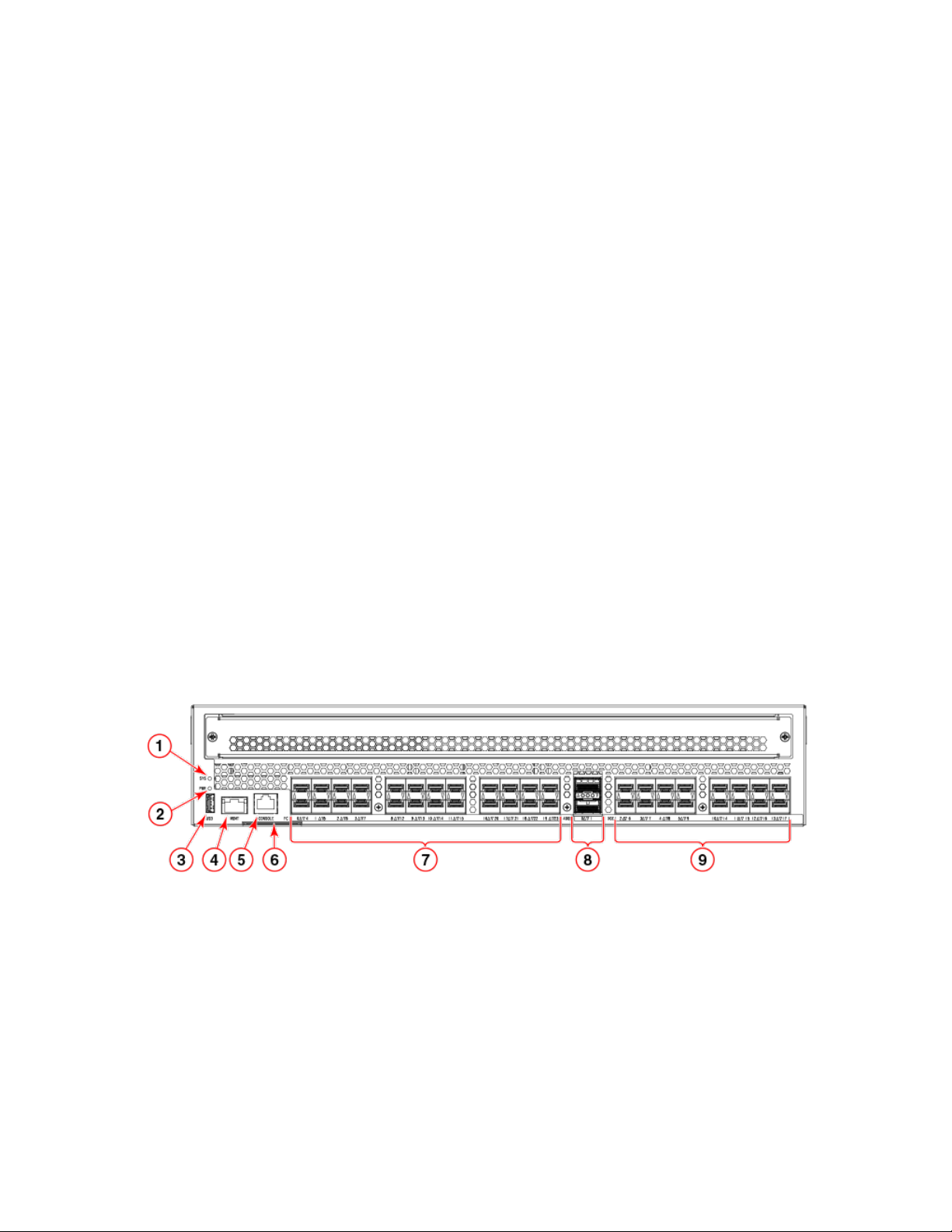
Port side of the switch
The following
FIGURE 1 Port side view of the Brocade 7840 Extension Switch
gures show the port side of the switch.
1. System Status LED
2. Power Status LED
3. USB port
4. Ethernet Management port
5. Console port (RJ-45)
6. Serial number pull-out tab
7. 16 Gbps FC ports (24)
8. 40 Gbps/GbE FCIP ports (QSFP) (2)
9. 1/10 GbE FCIP ports (16)
The Fibre Channel ports are numbered from left to right on the faceplate, as shown in the following gure.
Brocade 7840 Extension Switch Hardware Installation Guide
53-1003127-10 13
Nonport-side view
FIGURE 2 Port numbering in the switch
1. FC ports (16 Gbps) 0 through 7
2. FC ports (16 Gbps) 8 through 15
3. FC ports (16 Gbps) 16 through 23
4. FCIP ports (40 Gbps/GbE) 0 and 1 (QSFP)
5. FCIP ports (1/10 GbE) 2 through 9
6. FCIP ports (1/10 GbE) 10 through 17
You can have three Brocade Trunk groups on a fully licensed switch. Group 1 would consist of FC ports 0 through 7, group 2 would be
ports 8 through 15, and group 3 would be ports 16 through 23.
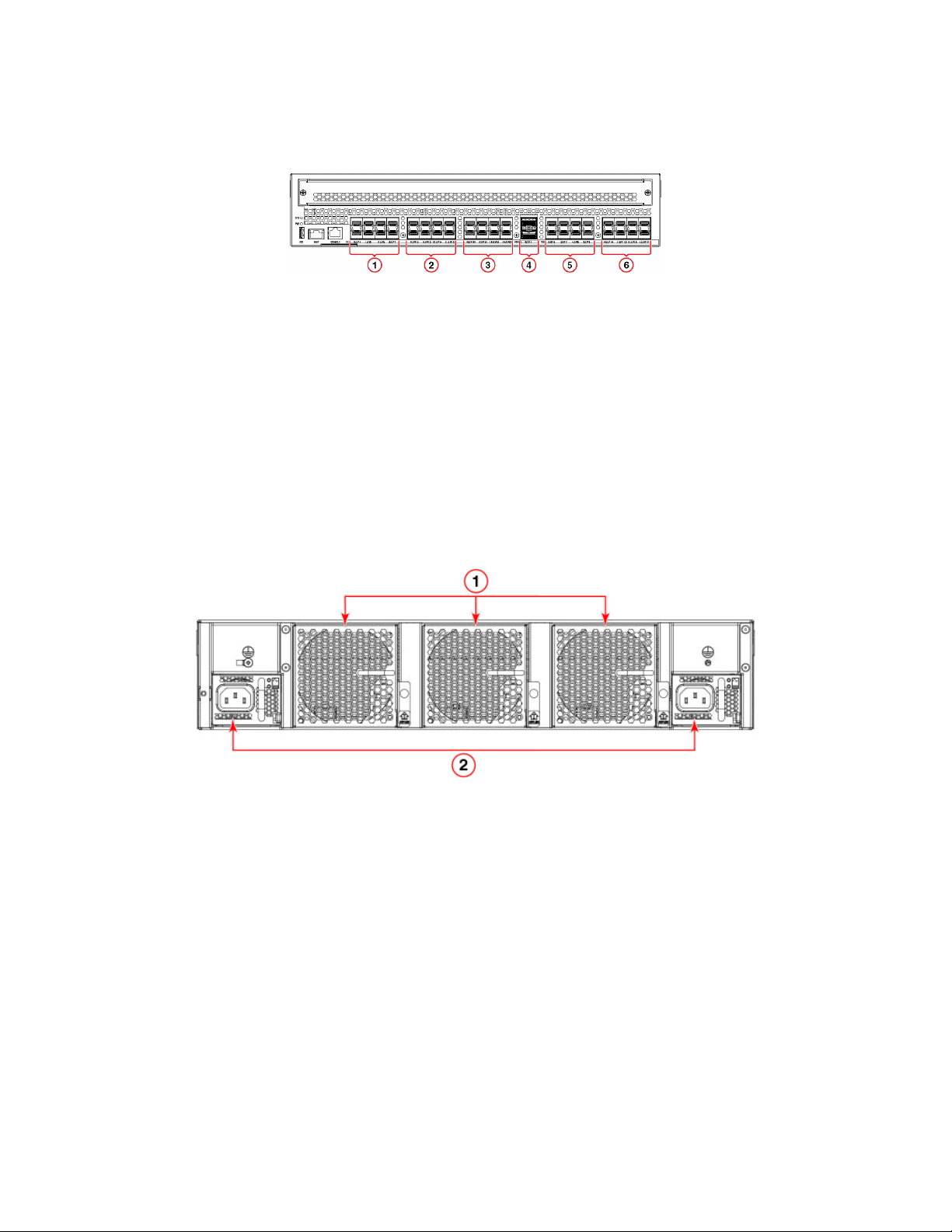
Nonport-side view
The following
FIGURE 3 Nonport-side view
gure shows the nonport side of the switch, which contains two power supply FRUs and three fan FRUs.
1. Fan FRUs (Fan 1, 2, and 3 from right to left) 2. Power supply FRUs with integral fans (PS 1 and 2 from right to left)
The following gure shows the components of the power supply and fan FRUs.
14 53-1003127-10
Brocade 7840 Extension Switch Hardware Installation Guide
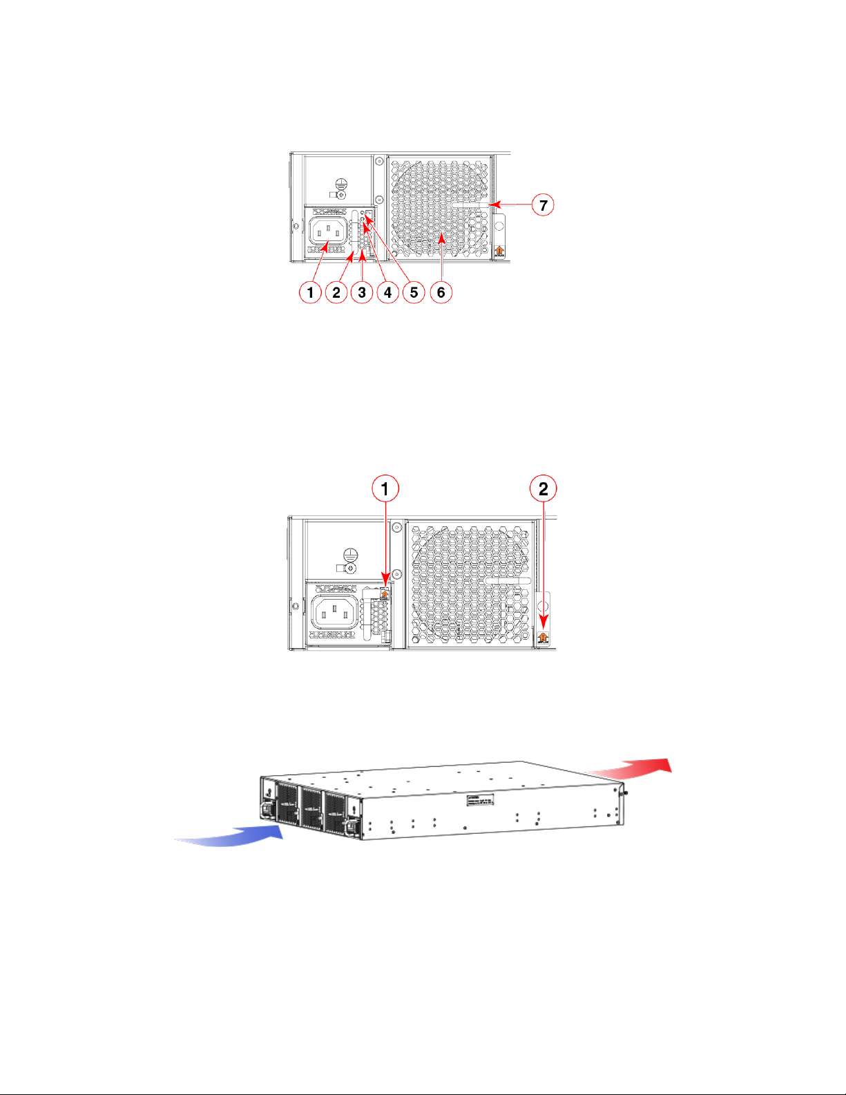
FIGURE 4 Power supply and fan details
Switch management
1. AC power socket
2. Handle
3. Integral fan air inlet
4. DC output status LED
5. AC input status LED
6. Fan air inlet
7. Handle
The following gure shows the airow labels on the power supply and fan FRUs.
FIGURE 5 Power supply and fan airow labels
1. Airow label for PSU integral fan 2. Airow label for fan FRU
The following gure shows the fan airow (Intake only) for the device. Exhaust airow fan is not supported in this release.
FIGURE 6 Intake
airow fans
Switch management
You can use the management functions built into the switch to monitor the fabric topology, port status, physical status, and other
information to help you analyze switch performance and to accelerate system debugging.
For information about upgrading the version of Fabric OS installed on your switch, refer to the Brocade Fabric OS Administration Guide
Brocade 7840 Extension Switch Hardware Installation Guide
53-1003127-10 15

Switch management
You can manage the switch using any of the management options listed in the following table.
TABLE 3 Management options for the Brocade 7840
Management tool Out-of-band support
Command line interface (CLI)
Up to two admin sessions and four user sessions simultaneously. For more information,
refer to the Brocade Fabric OS Administration Guide and the Brocade Fabric OS
Command Reference.
Brocade Network Advisor Ethernet (preferred) or console port connection
Brocade Web Tools
For information, refer to the Brocade Web Tools Administration Guide.
Standard SNMP applications
You can download the Brocade-specic MIB les from the downloads area of the
MyBrocade site under the applicable Fabric Operating System (FOS) release.
For information about SNMP support in Fabric OS and how to use MIBs, refer to the
Fabric OS Administrator's Guide. For release-specic SNMP enhancements, refer to the
release notes.
NOTE
Distribution of standard MIBs has been stopped. Download the required
standard MIBs from the www.oidview.com or www.mibdepot.com web sites.
Ethernet (preferred) or console port connection
Ethernet (preferred) or console port connection
Ethernet (preferred) or console port connection
Management Server
For information, refer to the Brocade Fabric OS Administration Guide and the Brocade
Fabric OS Command Reference.
Ethernet (preferred) or console port connection
16 53-1003127-10
Brocade 7840 Extension Switch Hardware Installation Guide

Preparing for Installation
• Installation and safety considerations........................................................................................................................................................17
• Installation precautions....................................................................................................................................................................................17
• Recommendations for cable management............................................................................................................................................18
• Items included with the switch......................................................................................................................................................................19
Installation and safety considerations
You can install the device in the following ways:
• As a standalone unit on a at surface.
• In an EIA rack using the Universal Two-Post Rack Kit or Universal Four-Post Rack Kit.
To install and operate the device successfully, ensure that the following requirements are met:
• The primary AC input is 100-240 VAC (the device autosenses input voltage), 50-60 Hz. 200-240 VAC is recommended.
• The primary outlet is correctly wired, protected by a circuit breaker, and grounded in accordance with local electrical codes. The
best practice is that each power supply obtains its power from a dierent protected and wired source.
• The supply circuit, line fusing, and wire size are adequate, as specied by the electrical rating on the device nameplate.
For power supply information, refer to Power supplies and fans on page 59.
To ensure adequate cooling, install the device with the nonport side, which contains the air intake vents, facing a cool-air aisle.
CAUTION
Make sure the airow around the front, and back of the device is not
restricted.
Verify that the ambient humidity remains between 20 and 85 percent while the device is operating.
CAUTION
Do not install the device in an environment where the operating ambient temperature might exceed 40°C (104°F).
If installing the device in a rack:
• The rack must be a standard EIA rack.
• Plan for a rack space that is 2U (8.89 cm; 3.5 in.) high, 48.3 cm (19 in.) wide, and at least 61 cm (24 in.) deep.
• Ground all equipment in the rack through a reliable branch circuit connection and maintain ground at all times. Do not rely on a
secondary connection to a branch circuit, such as a power strip.
• Ensure that airow and temperature requirements are met on an ongoing basis.
• Verify that the additional weight of the device does not exceed the rack’s weight limits or unbalance the rack in any way.
DANGER
Make sure the rack housing the device is adequately secured to prevent it from becoming unstable or falling over.
Installation precautions
Review all installation precautions before installing the device.
Brocade 7840 Extension Switch Hardware Installation Guide
53-1003127-10 17
Recommendations for cable management
General precautions
DANGER
The procedures in this manual are for qualied service personnel.
CAUTION
Changes or modications made to this device that are not expressly approved by the party responsible for compliance
could void the user's authority to operate the equipment.
DANGER
All ber-optic interfaces use Class 1 lasers.
DANGER
Use only optical transceivers that are qualied by Brocade Communications Systems LLC and comply with the FDA
Class 1 radiation performance requirements dened in 21 CFR Subchapter I, and with IEC 60825 and EN60825. Optical
products that do not comply with these standards might emit light that is hazardous to the eyes.
Power precautions
This device might have more than one power cord. To reduce the risk of electric shock, disconnect both power cords before servicing.
DANGER
Remove both power cords before servicing.
DANGER
Disconnect the power cord from all power sources to completely remove power from the device.
CAUTION
Before plugging a cable into any port, be sure to discharge the voltage stored on the cable by touching the electrical
contacts to ground surface.
Connect the power cord only to a grounded outlet.
DANGER
Make sure that the power source circuits are properly grounded, then use the power cord supplied with the device to
connect it to the power source.
This product is designed for an IT power system with phase-to-phase voltage of 230V. After operation of the protective device, the
equipment is still under voltage if it is connected to an IT power system.
Recommendations for cable management
Cables can be organized and managed in a variety of ways, such as by using cable channels or patch panels. Note the following
recommendations:
• Plan cable management before installing the device in a rack.
• Leave at least 1 meter (3 feet) of slack for each port cable. This provides room to remove and replace the device, allows for
inadvertent movement of the rack, and helps prevent the cables from being bent to less than the minimum bend radius.
18 53-1003127-10
Brocade 7840 Extension Switch Hardware Installation Guide

NOTE
A 50-micron cable should not be bent to a radius less than 2 in. under full tensile load and 1.2 in. with no tensile load. Tie
wraps are not recommended for optical cables because they are easily overtightened.
Items included with the switch
The following items are included with the standard shipment of the Brocade 7840:
• The Brocade 7840, containing two combined power supply FRUs with integral fans
• Three individual fan FRUs
• The following rack mount kits are available options:
– Fixed rack mount kit, with installation instructions
– Mid-mount kit, with installation instructions
• All Fibre Channel ports contain 16 Gbps SWL or LWL SFP transceivers
• One accessory kit, containing the following items:
– China-ROHS Hazardous/Toxic Substance Content Chart
– Documentation reference card (describes where to nd relevant documentation)
– 24 16 G Brocade branded SWL or LWL SFPs, depending on the switch SKU ordered
– Network Advisor download insert
– Rubber mounting feet (to be used when setting up the Extension Switch as a standalone unit)
– Two grounded 6-ft. (approximately 1.83 m) power cords:
› Power plug type: NEMA5-15
› Power plug current/voltage rating: 15A/125V
› Cordage type: SJT
› Current rating/wire gauge: 13A/16AWG with a 105°C (221°F) temperature rating
› Connector at system end of cordset: IEC 60320/C13
› Two power cord retainers
– One RJ-45 serial cable (10 ft. or approximately 3 m.). The Extension Switch uses an RJ-45 connector for the console port.
An RJ-45 to DB-9 adapter is also provided with the switch.
Items included with the switch
Brocade 7840 Extension Switch Hardware Installation Guide
53-1003127-10 19

20 53-1003127-10
Brocade 7840 Extension Switch Hardware Installation Guide

Mounting the Device
• Setting up the device as a standalone unit..............................................................................................................................................21
• Installing the Universal Two-Post Rack Kit (XBR-R000294).........................................................................................................21
• Installing the Universal Four-Post Rack Kit (XBR-R000296)........................................................................................................30
Setting up the device as a standalone unit
The device can be
the device as a standalone unit.
1. Unpack the device and verify that all ordered items are present.
2. Clean the four corner depressions on the bottom of the device and place a rubber foot in each one. This helps prevent the
device from accidentally sliding o the supporting surface.
3. Place the device on a stable, at surface.
congured as a standalone unit, which means that it resides outside of a rack. Perform the following steps to congure
Installing the Universal Two-Post Rack Kit (XBRR000294)
Use the following instructions to install a Brocade 1U or 2U device in a two-post telecommunications (Telco) rack using the Universal
Two-Post Rack Kit (XBR-R000294).
There are two ways you can mount the device in a two-post rack:
• With the port side
• With the posts mounted to the mid-section of the device
Observe the following when mounting this device:
• Two people are required to install the device in a rack. One person should hold the device, while the other while the other screws
in the front and rear brackets.
• Before mounting your device, review any specic installation and facility requirements in this Hardware Installation Guide.
• Hardware devices illustrated in these procedures are only for reference and may not depict the device you are installing into the
rack.
ush with the front posts
Time and items required
Allow 15 to 30 minutes to complete the installation.
The following items are required to install the device using the Universal Two-Post Rack Kit:
• #2 Phillips torque screwdriver
• 1/4-inch slotted-blade torque screwdriver
Parts list
The following parts are provided with the Universal Two-Post Rack Kit Installation (XBR-R000294).
Brocade 7840 Extension Switch Hardware Installation Guide
53-1003127-10 21
Installing the Universal Two-Post Rack Kit (XBR-R000294)
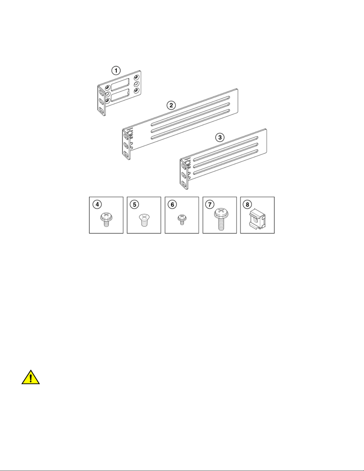
FIGURE 7 Rack kit parts
1. Front brackets (2)
2. Rear brackets, 3-5 inch post (2)
3. Rear brackets, 5-6 inch post (2)
4. Screw, 8-32 x 5/16-in., panhead Phillips (8)
5. Screw, 8-32 x 5/16-in., athead Phillips (16)
6. Screw, 6-32 x 1/4-in., panhead Phillips (8)
7. Screw, 10-32 x 5/8-in., panhead Phillips (8)
8. Retainer nut, 10-32 (8)
Ensure that the items listed and illustrated above are included in the kit. Note that not all parts may be used with certain installations
depending on the device type.
Flush-front mounting
Observe the following notes when using this procedure:
• The device must be turned o and disconnected from the fabric during this procedure.
• The illustrations in this document show a 1U device, but the instructions are the same for a 2U device.
• The illustrations for this procedure show a two-post rack with narrow posts (3- to 5-inch) as an example.
• The illustrations in the rack installation procedures are for reference only and may not show the actual device.
CAUTION
Use the screws specied in the procedure. Using longer screws can damage the
device.
Complete the following tasks to install the device in a rack:
1. Attaching the front brackets to the device on page 23
2. Attaching the front brackets to the rack on page 23
22 53-1003127-10
Brocade 7840 Extension Switch Hardware Installation Guide
Installing the Universal Two-Post Rack Kit (XBR-R000294)
3. Attaching the rear brackets to the rack on page 24
4. Attaching the rear brackets to the device on page 25
Attaching the front brackets to the device
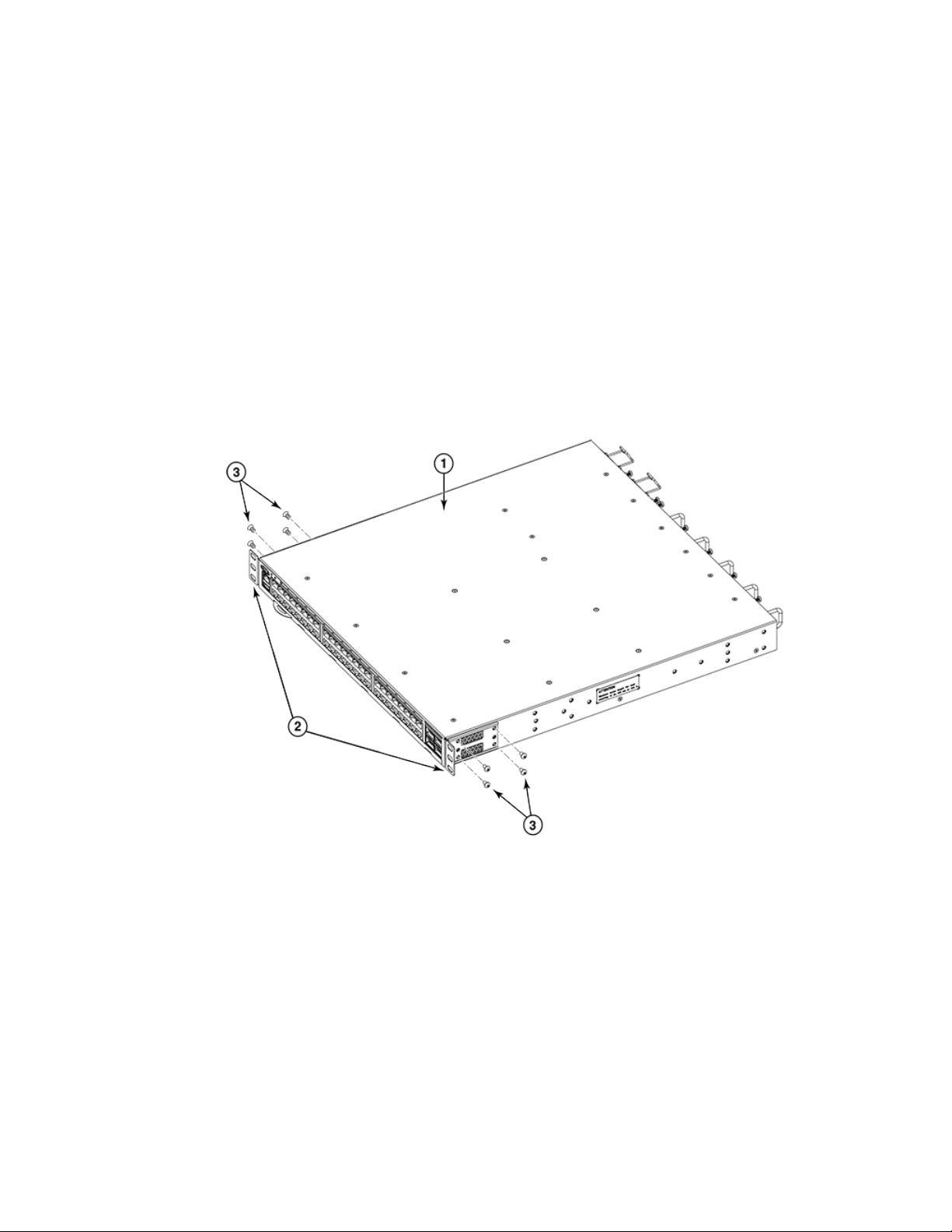
Complete the following steps to attach the front brackets to the device.
1. Position the right front bracket with the at side against the right side of the device, as shown in Figure 8.
2. Insert four 8-32 x 5/16-in. athead screws through the vertically aligned holes in the bracket and then into the holes on the
side of the device. Use the upper and lower screw holes, leaving the center holes empty.
3. Repeat step 1 and step 2 to attach the left front bracket to the left side of the device.
4. Tighten all the 8-32 x 5/16-in. screws to a torque of 15 in-lb (17 cm-kg).
FIGURE 8 Attaching the front brackets
1. The Brocade device
2. Front brackets, right and left
3. Screws, 8-32 x 5/16-in., athead Phillips
Attaching the front brackets to the rack
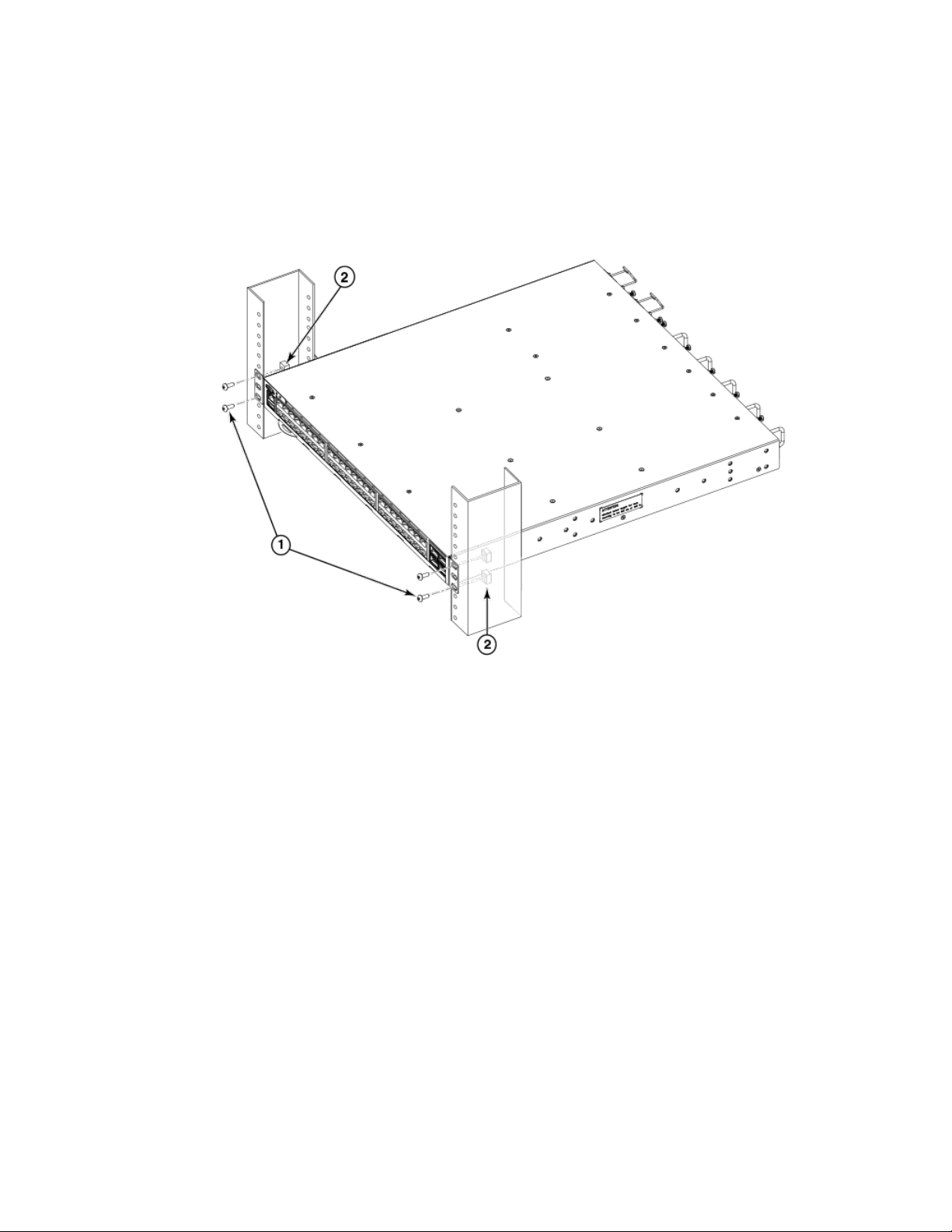
Complete the following steps to install the device in the rack.
1. Position the device in the rack, as shown in (Figure 9), providing temporary support under the device until the rack kit is fully
secured to the rack.
2. Attach the right front bracket to the right rack upright using two 10-32 x 5/8-in. panhead screws and two retainer nuts. Use the
upper and lower holes in the bracket.
Brocade 7840 Extension Switch Hardware Installation Guide
53-1003127-10 23
Installing the Universal Two-Post Rack Kit (XBR-R000294)
3. Attach the left front bracket to the left rack upright using two 10-32 x 5/8-in. panhead screws and two retainer nuts.
Use the upper and lower holes in the bracket.
4. Tighten all the 10-32 x 5/8-in. screws to a torque of 25 in-lb. (29 cm-kg).
FIGURE 9 Attaching front brackets to a rack
1. Screws, 10-32 x 5/8-in., panhead Phillips 2. Retainer nuts, 10-32
Attaching the rear brackets to the rack
Complete the following steps to attach the rear brackets to the rack.
1. Select the proper length bracket for your post width. If your posts are three to
INCH. If your posts are ve to six inches wide, use the brackets marked 5-6 INCH.
2. Position the right rear bracket in the right rear of the device, as shown in Figure 10.
3. Attach the bracket to the right rack upright using two 10-32 x 5/8-in. panhead screws and two retainer nuts. Use the upper and
lower holes in the bracket.
4. Repeat step 2 and step 3 to attach the left rear bracket to the left rack upright.
ve inches wide, use the brackets marked 3-5
24 53-1003127-10
Brocade 7840 Extension Switch Hardware Installation Guide
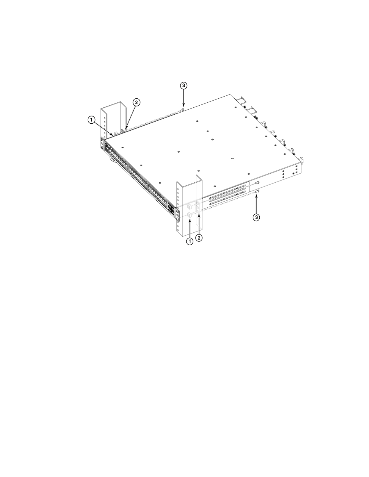
5. Tighten all the 10-32 x 5/8-in. screws to a torque of 25 in-lb. (29 cm-kg).
FIGURE 10 Attaching the rear brackets to a rack
Installing the Universal Two-Post Rack Kit (XBR-R000294)
1. Retainer nuts, 10-32
2. Rear brackets
3. Screws, 10-32 x 5/8-in., panhead Phillips
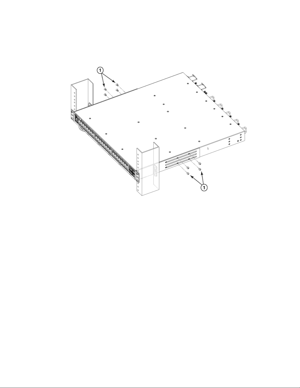
Attaching the rear brackets to the device
Complete the following steps to attach the rear brackets to the device.
1. Align the right rear bracket to the right rear of the device and use four 8-32 x 5/16-in. panhead screws to attach the bracket to
the device, as shown in Figure 11. Be sure to insert the screws through the upper and lower slots in the bracket.
2. Align the left rear bracket to the left rear of the device and use four 8-32 x 5/16-in. panhead screws to attach the bracket to the
device. Again, use the upper and lower slots in the bracket.
Brocade 7840 Extension Switch Hardware Installation Guide
53-1003127-10 25
Installing the Universal Two-Post Rack Kit (XBR-R000294)
3. Tighten all the 8-32 x 5/16-in. screws to a torque of 15 in-lb (17 cm-kg).
FIGURE 11 Attaching the rear brackets to the device
1. Screws, 8-32 x 5/16-in., panhead Phillips
Mid-mounting
Observe the following notes when using this procedure:
• The device must be turned
• The illustrations in this document show a 1U device, but the instructions are the same for a 2U device.
• The illustrations in the rack installation procedures are for reference only and may not show the actual device.
Complete the following tasks to install the device in a rack:
1. Attaching the front brackets to the device on page 26
2. Attaching the front brackets to the rack on page 27
3. Attaching the rear brackets to the rack on page 28
4. Attaching the rear brackets to the device on page 29
Attaching the front brackets to the device
Complete the following steps to attach the front brackets to the device.
1. Position the right front bracket with the at side against the right side of the device, as shown in Figure 12.
o and disconnected from the fabric during this procedure.
26 53-1003127-10
Brocade 7840 Extension Switch Hardware Installation Guide
 Loading...