

Page 1

HARDWARE INSTALLATION GUIDE
Brocade 7810 Extension Switch
Hardware Installation Guide
7810-IG101
28 September 2018
Page 2

Copyright © 2018 Brocade Communications Systems LLC. All Rights Reserved. Brocade and the stylized B logo are among the trademarks of Brocade
Communications Systems LLC. Broadcom, the pulse logo, and Connecting everything are among the trademarks of Broadcom. The term "Broadcom"
refers to Broadcom Inc. and/or its subsidiaries.
Brocade, a Broadcom Inc. Company, reserves the right to make changes without further notice to any products or data herein to improve reliability,
function, or design. Information furnished by Brocade is believed to be accurate and reliable. However, Brocade does not assume any liability arising out of
the application or use of this information, nor the application or use of any product or circuit described herein, neither does it convey any license under its
patent rights nor the rights of others.
The product described by this document may contain open source software covered by the GNU General Public License or other open source license
agreements. To nd out which open source software is included in Brocade products, view the licensing terms applicable to the open source software, and
obtain a copy of the programming source code, please visit https://www.broadcom.com/support/bre-channel-networking/tools/oscd.
2 7810-IG101
Brocade 7810 Extension Switch Hardware Installation Guide
Page 3

Contents
Introduction.......................................................................................................................................................................................................................... 6
About This Document..............................................................................................................................................................................................................................6
Supported Hardware and Software.................................................................................................................................................................................................... 6
Notes, Cautions, and Warnings............................................................................................................................................................................................................ 6
Resources......................................................................................................................................................................................................................................................7
Contacting Brocade Technical Support............................................................................................................................................................................................ 7
Document Feedback................................................................................................................................................................................................................................7
Device Overview..................................................................................................................................................................................................................8
Functionality Features..............................................................................................................................................................................................................................8
Hardware Features.....................................................................................................................................................................................................................................9
License Options..........................................................................................................................................................................................................................................9
Port-Side View.........................................................................................................................................................................................................................................10
Nonport-Side View.................................................................................................................................................................................................................................10
Device Management Options............................................................................................................................................................................................................11
GbE Optical and Copper Port Operation......................................................................................................................................................................................12
Preparing for the Installation..........................................................................................................................................................................................13
Safety Precautions..................................................................................................................................................................................................................................13
General Precautions......................................................................................................................................................................................................................13
ESD Precautions............................................................................................................................................................................................................................14
Power Precautions........................................................................................................................................................................................................................14
Lifting and Weight-Related Precautions.............................................................................................................................................................................. 15
Laser Precautions..........................................................................................................................................................................................................................16
Facility Requirements............................................................................................................................................................................................................................16
Quick Installation Checklist.................................................................................................................................................................................................................16
Pre-Installation Tasks................................................................................................................................................................................................................... 16
Installation and Initial Conguration........................................................................................................................................................................................17
Shipping Carton Contents...................................................................................................................................................................................................................18
Mounting the Device........................................................................................................................................................................................................19
Mounting Options...................................................................................................................................................................................................................................19
Precautions Specic to Mounting....................................................................................................................................................................................................19
Standalone Installation..........................................................................................................................................................................................................................20
Installing the Universal Four-Post Rack Kit (XBR-R000296).............................................................................................................................................20
Time and Items Required...........................................................................................................................................................................................................21
Parts List............................................................................................................................................................................................................................................21
Flush-Front Mounting..................................................................................................................................................................................................................23
Flush-Rear (Recessed) Mounting...........................................................................................................................................................................................28
Installing the Universal Two-Post Rack Kit (XBR-R000294)..............................................................................................................................................33
Time and Items Required...........................................................................................................................................................................................................34
Parts List............................................................................................................................................................................................................................................34
Flush-Front Mounting..................................................................................................................................................................................................................35
Mid-Mounting.................................................................................................................................................................................................................................39
Initial Setup and Verication.......................................................................................................................................................................................... 44
Items Required.........................................................................................................................................................................................................................................44
Providing Power to the Device..........................................................................................................................................................................................................44
Brocade 7810 Extension Switch Hardware Installation Guide
7810-IG101 3
Page 4

Establishing a First-Time Serial Connection................................................................................................................................................................................45
Conguring the IP Address.................................................................................................................................................................................................................46
Using DHCP to Set the IP Address.......................................................................................................................................................................................46
Setting a Static IP Address........................................................................................................................................................................................................ 46
Setting the Date and Time...................................................................................................................................................................................................................46
Setting the Time Zone................................................................................................................................................................................................................. 47
Synchronizing the Local Time with an External Source.................................................................................................................................................48
Customizing the Chassis Name and Switch Name..................................................................................................................................................................48
Establishing an Ethernet Connection..............................................................................................................................................................................................48
Setting the Domain ID...........................................................................................................................................................................................................................49
Verifying Correct Operation................................................................................................................................................................................................................49
Backing Up the Conguration........................................................................................................................................................................................................... 51
Powering Down the Device.................................................................................................................................................................................................................51
Installing Transceivers and Cables................................................................................................................................................................................52
Time and Items Required.....................................................................................................................................................................................................................52
Precautions Specic to Transceivers and Cables...................................................................................................................................................................... 53
Cleaning the Fiber-Optic Connectors............................................................................................................................................................................................ 53
Managing Cables.................................................................................................................................................................................................................................... 53
Installing an SFP+ Transceiver...........................................................................................................................................................................................................54
Replacing an SFP+ Transceiver........................................................................................................................................................................................................ 56
Verifying the Operation of New Transceivers..............................................................................................................................................................................58
Monitoring the Device..................................................................................................................................................................................................... 59
Interpreting Port-Side LEDs...............................................................................................................................................................................................................59
System Power LED......................................................................................................................................................................................................................59
System Status LED.......................................................................................................................................................................................................................60
Ethernet Management Port Link Status and Activity LEDs .......................................................................................................................................60
FC Port Status LED......................................................................................................................................................................................................................61
GbE Port Status LEDs.................................................................................................................................................................................................................61
Interpreting Nonport-Side LEDs......................................................................................................................................................................................................62
Power Supply and Fan Assembly Status LED..................................................................................................................................................................62
Interpreting POST Results..................................................................................................................................................................................................................63
Interpreting BOOT Results................................................................................................................................................................................................................. 63
Running Diagnostic Tests.................................................................................................................................................................................................................... 64
Power Supply and Fan Assembly..................................................................................................................................................................................65
Power Supply and Fan Assembly Overview............................................................................................................................................................................... 65
Precautions Specic to the Power Supply and Fan Assemblies.........................................................................................................................................66
Identifying the Airow Direction........................................................................................................................................................................................................66
Power Supply and Fan Assembly Unit Fault Indicators..........................................................................................................................................................67
Power Supply and Fan Assembly Task Guide............................................................................................................................................................................ 67
Installing an Additional Power Supply and Fan Assembly (Hot-Install).................................................................................................................. 67
Replacing a Power Supply and Fan Assembly (Hot-Swap).........................................................................................................................................67
Replacing Both Power Supply and Fan Assemblies (Cold-Swap)............................................................................................................................68
Time and Items Required.....................................................................................................................................................................................................................68
Recording Power Supply and Fan Assembly Critical Information......................................................................................................................................68
Removing a Power Supply and Fan Assembly..........................................................................................................................................................................69
Inserting a New Power Supply and Fan Assembly...................................................................................................................................................................69
Verifying the Operation of the Power Supply and Fan Assemblies...................................................................................................................................71
Brocade 7810 Technical Specications..................................................................................................................................................................... 72
4 7810-IG101
Brocade 7810 Extension Switch Hardware Installation Guide
Page 5

System Specications...........................................................................................................................................................................................................................72
Fibre Channel............................................................................................................................................................................................................................................72
Ethernet.......................................................................................................................................................................................................................................................72
Other Ports................................................................................................................................................................................................................................................ 73
LEDs.............................................................................................................................................................................................................................................................73
Other Cables and Connectors...........................................................................................................................................................................................................73
Weight and Physical Dimensions.....................................................................................................................................................................................................73
Environmental Requirements.............................................................................................................................................................................................................74
Power Supply Specications (Per PSU)........................................................................................................................................................................................ 74
Power Consumption (Typical Conguration)...............................................................................................................................................................................75
Power Consumption (Maximum Conguration).........................................................................................................................................................................75
Power Consumption (Idle Conguration)...................................................................................................................................................................................... 75
Data Port Specications (Fibre Channel).......................................................................................................................................................................................75
Data Port Specications (Ethernet)..................................................................................................................................................................................................76
Fibre Channel Data Transmission Ranges................................................................................................................................................................................... 76
Serial Port Specications (Pinout RJ-45).....................................................................................................................................................................................76
Serial Port Specications (Protocol)................................................................................................................................................................................................ 77
Memory Specications.........................................................................................................................................................................................................................77
Regulatory Compliance (EMC)..........................................................................................................................................................................................................77
Regulatory Compliance (Safety)........................................................................................................................................................................................................78
Regulatory Compliance (Environmental).......................................................................................................................................................................................78
Regulatory Statements....................................................................................................................................................................................................79
BSMI Statement (Taiwan).................................................................................................................................................................................................................... 79
Canadian Requirements.......................................................................................................................................................................................................................79
CE Statement............................................................................................................................................................................................................................................79
China CCC Statement...........................................................................................................................................................................................................................80
China RoHS...............................................................................................................................................................................................................................................81
Croatia Statement...................................................................................................................................................................................................................................81
FCC Warning (U.S. Only)......................................................................................................................................................................................................................82
Germany Statement...............................................................................................................................................................................................................................82
KCC Statement (Republic of Korea).................................................................................................................................................................................................82
VCCI Statement.......................................................................................................................................................................................................................................82
Taiwan ROHS Certication................................................................................................................................................................................................................. 83
Turkey Statement.................................................................................................................................................................................................................................... 83
Ukraine Statement..................................................................................................................................................................................................................................84
Cautions and Danger Notices........................................................................................................................................................................................85
Danger Notices........................................................................................................................................................................................................................................85
General Dangers............................................................................................................................................................................................................................ 85
Electrical Dangers..........................................................................................................................................................................................................................85
Dangers Related to Equipment Weight................................................................................................................................................................................87
Laser Dangers.................................................................................................................................................................................................................................87
Cautions......................................................................................................................................................................................................................................................87
General Cautions............................................................................................................................................................................................................................88
Electrical Cautions.........................................................................................................................................................................................................................88
Revision History................................................................................................................................................................................................................91
7810-IG101; September 28, 2018.............................................................................................................................................................................................91
7810-IG100; August 28, 2018.....................................................................................................................................................................................................91
Brocade 7810 Extension Switch Hardware Installation Guide
7810-IG101 5
Page 6
Introduction
• About This Document.........................................................................................................................................................................................6
• Supported Hardware and Software...............................................................................................................................................................6
• Notes, Cautions, and Warnings.......................................................................................................................................................................6
• Resources................................................................................................................................................................................................................7
• Contacting Brocade Technical Support.......................................................................................................................................................7
• Document Feedback...........................................................................................................................................................................................7
About This Document
This hardware installation guide contains procedures and safety requirements for installing the Brocade 7810 Extension Switch into a
rack system or as a standalone device. Also provided are steps to initially congure the switch for operation, verify and monitor operation,
replace switch eld-replaceable units (FRUs), and install transceivers and cables. Complete technical specications for the switch are also
included.
Supported Hardware and Software
The following tables list the power supply and fan assemblies and rack mount kits supported on this device.
TABLE 1 Power Supply and Fan Assemblies
Part Number Description Introduced (OS) Currently Supported (OS)
XBR-G250WPSAC-R 250W AC power supply with cooling from the nonport-
side of the switch to the port side (port-side exhaust)
Fabric OS 8.2.1 Yes
TABLE 2 Rack Mount Kits
Part Number Description
XBR-R000294 Universal two-post mid-mount or ush-mount rack kit
XBR-R000296 Universal four-post xed-rack mount kit
Notes, Cautions, and Warnings
Notes, cautions, and warning statements may be used in this document.
NOTE
A Note provides a tip, guidance, or advice, emphasizes important information, or provides a reference to related information.
CAUTION
A Caution statement alerts you to situations that can be potentially hazardous to you or cause damage to hardware,
rmware, software, or data.
DANGER
A Danger statement indicates conditions or situations that can be potentially lethal or extremely hazardous to you. Safety
labels are also attached directly to products to warn of these conditions or situations.
6 7810-IG101
Brocade 7810 Extension Switch Hardware Installation Guide
Page 7

Document Feedback
Resources
Visit the Brocade website to locate related documentation for your product and additional Brocade resources.
White papers, data sheets, and the most recent versions of Brocade software and hardware manuals are available at https://
www.broadcom.com/products/bre-channel-networking/. Product documentation for all supported releases is available to registered
users at MyBrocade.
Click the Support tab and select Document Library to access product documentation on MyBrocade or https://www.broadcom.com/
products/bre-channel-networking/. You can locate documentation by product or by operating system.
Release notes are bundled with software downloads on MyBrocade. Links to software downloads are available on the MyBrocade landing
page and in the Document Library.
Contacting Brocade Technical Support
For product support information and the latest information on contacting the Technical Assistance Center, go to https://
www.broadcom.com/support/bre-channel-networking/. If you have purchased Brocade product support directly from Brocade, use
one of the following methods to contact the Brocade Technical Assistance Center 24x7.
Online Telephone
For nonurgent issues, the preferred method is to go to MyBrocade
(my.brocade.com) and then go to one of the following sites:
• My Cases
• Software Downloads
• Licensing tools
• Knowledge Base
If you purchased Brocade product support from a Brocade OEM/solution provider, contact your OEM/solution provider for all your
product support needs.
• OEM/solution providers are trained and certied by Brocade to support Brocade products.
• Brocade provides backline support for issues that cannot be resolved by the OEM/solution provider.
• Brocade Supplemental Support augments your existing OEM support contract, providing direct access to Brocade expertise.
For more information, contact Brocade or your OEM.
• For questions regarding service levels and response times, contact your OEM/solution provider.
Required for Severity 1-Critical and Severity 2-High issues:
• North America: 1-800-752-8061 (Toll-free)
• International: 1-669-234-1001 (Not toll-free)
Toll-free numbers are available in many countries and are listed at https://
www.broadcom.com/support/bre-channel-networking/.
Document Feedback
Quality is our rst concern. We have made every eort to ensure the accuracy and completeness of this document. However, if you nd
an error or an omission or if you think that a topic needs further development, we want to hear from you. Send your feedback to
documentation.pdl@broadcom.com. Provide the publication title, publication number, topic heading, page number, and as much detail as
possible.
Brocade 7810 Extension Switch Hardware Installation Guide
7810-IG101 7
Page 8

Device Overview
• Functionality Features.........................................................................................................................................................................................8
• Hardware Features...............................................................................................................................................................................................9
• License Options.................................................................................................................................................................................................... 9
• Port-Side View....................................................................................................................................................................................................10
• Nonport-Side View...........................................................................................................................................................................................10
• Device Management Options.......................................................................................................................................................................11
• GbE Optical and Copper Port Operation.................................................................................................................................................12
Functionality Features
The Brocade 7810 supports the following functions:
• Four logical Extension tunnels with combined maximum bandwidth of 2.5Gb/s to allow for scalable connectivity between sites.
– The switch does not support FCIP connectivity to the Brocade 7800 or FX8-24 blade because connections to these
products are inoperable.
– The switch does support FCIP connectivity to the Brocade 7840 or SX6 blade.
• Hybrid mode only. This mode enables FCIP and IP Extension trac to traverse through the tunnels.
• Extension trunking. This feature allows multiple IP source and destination address pairs (dened as circuits) using multiple
1/10GbE interfaces to provide high-bandwidth Extension tunnel and lossless failover resiliency. In addition, each circuit
supports the following QoS classes as individual TCP connections:
– Class-F
– FC-High
– FC-Medium
– FC-Low Priority
– IPEXT-High,
– IPEXT-Medium
– IPEXT-Low Priority
• ARL enforces a minimum bandwidth guarantee for each circuit and permits adaptive utilization up to a set maximum bandwidth
level. ARL optimizes network utilization of available bandwidth.
• Software-based compression to deliver higher throughput over lower bandwidth links in the wide area network, optimizing the
cost eciencies of Extension. The Brocade 7810 compresses FC frames and IP datagrams before they are encapsulated into
Extension batches and transported across the WAN.
• Key protocol features that optimize performance of Extension over IP networks include WAN Optimized TCP (WO-TCP), 9K
jumbo frames, and end-to-end Path MTU (PMTU) auto-discovery.
• Hardware-based IPsec supporting a mixture of secure and nonsecure tunnels on the same Ethernet port, jumbo frames, and
VLAN-tagged connections. The Brocade 7810 IPsec function is capable of supporting both IPv4 and IPv6.
• FastWrite and Open Systems Tape Pipelining (OSTP) to mitigate the latency eect of a long-distance Extension connection
over an IP WAN.
• A built-in WAN link tester (WTool) that generates trac over an IP connection to test for maximum throughput, congestion, loss
percentage, out-of-order delivery, latency, and other network conditions. This tester helps determine the health of a WAN link
before deploying it for use.
• NVMe and VMOSAN trac types.
8 7810-IG101
Brocade 7810 Extension Switch Hardware Installation Guide
Page 9

• REST APIs for conguration and monitoring.
• Fiber Channel Routing (FCR) on FC ports, such as EX_Ports.
• Fabric Vision advanced monitoring to provide the following functions:
– Policy-based monitoring for Extension connectivity and WAN anomalies using multilayer metrics.
– Flow monitoring that reports IOPS and the data rate of individual I/O ows of inter-DC replication and tape backup
operations.
– Flow generator that generates FC frames for a dened ow with a default or a customized size and pattern. These frames
are sent across an Extension tunnel to help validate end-to-end network setup and conguration.
Hardware Features
The Brocade 7810 provides the following hardware features:
• Twelve Fibre Channel optical ports that support the following transceivers:
– 32Gb/s short wavelength (SWL) and long wavelength (LWL) small form-factor pluggable plus (SFP+) optical transceivers
that can auto-negotiate to 32Gb/s, 16Gb/s, or 8Gb/s.
– 16Gb/s SWL and LWL SFP+ optical transceivers that can auto-negotiate to 16Gb/s, 8Gb/s, or 4Gb/s.
• Six GbE optical ports that support the following transceivers for operation at 10Gb/s or 1Gb/s:
– 10GbE SFP+ short reach (SR)
– 10GbE SFP+ long reach (LR)
– 10GbE SFP+ ultra short reach (USR)
– 1GbE SFP+ SR
– 1GbE SFP+ LR
License Options
NOTE
Only a total of six GbE ports can operate at one time, either all six optical ports or a mixture of two RJ-45 copper
ports and four optical ports. For details, see GbE Optical and Copper Port Operation on page 12.
• Two GbE ports that support 1GbE copper RJ-45 CAT5 transceivers.
• One RJ-45 Ethernet management port with 10/100/1000-Mbps auto-negotiating capability.
• One RS-232, 3-wire (Tx, Rx, and GND) universal asynchronous receiver/transmitter (UART) serial port to BMC with RJ-45
connector.
• One USB port to provide storage for rmware updates, output of the supportSave command, and storage for conguration
uploads and downloads.
• Two hot-swappable, redundant, 250W AC/DC power supply assemblies, each integrated with three fans. These assemblies
provide nonport-side air intake (port-side exhaust) operation only.
• Rack-mountable 1U chassis.
• High performance T1022 control processor with two cores operating at 1.2 GHz for high performance, scalability, and
advanced Fabric Vision functionality.
License Options
The Brocade 7810 base model can be upgraded with an Upgrade license. This license increases the number of FC, VE, and GbE ports;
it increases GbE port speeds; and it adds support for FC and extension trunking, Fabric Vision, FC routing, and other Fabric OS features.
Refer to the Brocade Fabric OS Software Licensing Guide for full details.
Brocade 7810 Extension Switch Hardware Installation Guide
7810-IG101 9
Page 10
Port-Side View
NOTE
Optical ports 2-7 only operate at 1Gb/s in the base-model conguration.
Port-Side View
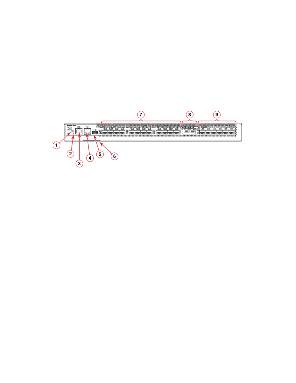
The following illustration identies system LEDs and ports on the port-side of the Brocade 7810 Extension Switch.
FIGURE 1 Port-Side View
1. System Power LED
2. System Status LED
3. Serial Console Port (RJ-45)
4. Ethernet Management Port (RJ-45)
5. USB Port
NOTE
All ports are connected to a single ASIC.
6. Serial Number Pull-out Tab
7. 32Gb/s SFP+ FC Ports (0-11)
8. 1GbE Copper (RJ-45) Ports (0-1)
9. 1/10GbE SFP+ Ports (2-7)
Nonport-Side View
The following illustration identies components on the nonport-side of the Brocade 7810 Extension Switch.
10 7810-IG101
Brocade 7810 Extension Switch Hardware Installation Guide
Page 11

FIGURE 2 Nonport-Side View with AC Power Supply and Fan Assembly Units
Device Management Options
1. Ground Sticker
2. Ground Cable Connector
3. Power Supply and Fan Assembly 2
4. Power Supply and Fan Assembly 1
5. Captive Screw
6. Handle
7. Power Supply and Fan Assembly Status LED
8. Power-On Switch
9. Power Supply Receptacle
NOTE
The fans in each power supply and fan assembly are integrated as a single fan unit. Output of the fanshow command displays
status for fan 1 (power supply and fan assembly 1) and fan 2 (power supply and fan assembly 2).
Device Management Options
You can use the management functions built into the device to monitor the fabric topology, port status, physical status, and other
information to help you analyze switch performance and accelerate system debugging. The device automatically performs a power-on
self-test (POST) each time it is turned on. A RASlog message is generated for any detected startup errors.
You can manage the device using any of the management options listed in the following table.
TABLE 3 Management Options for the Device
Management Tool Out-of-Band Support Reference Documents
Command line interface (CLI)
Up to two admin sessions and four user
sessions simultaneously.
Brocade EZSwitchSetup
EZSwitchSetup helps to complete the basic
conguration for a single-switch setup.
Brocade Web Tools Ethernet or serial connection Brocade Web Tools Administration Guide
Standard SNMP applications Ethernet or serial connection Fabric OS MIB Reference
Management Server Ethernet or serial connection Brocade Fabric OS Administration Guide
Fabric OS REST API Ethernet or serial connection Brocade Fabric OS REST API Reference
SANscape
SANscape must be purchased separately
Ethernet or serial connection Brocade Fabric OS Administration Guide
Brocade Fabric OS Command Reference
Ethernet or serial connection EZSwitchSetup Software Installation Guide
EZSwitchSetup Guide
Brocade Fabric OS Command Reference
Ethernet or serial connection Brocade SANscape User Guide
Brocade 7810 Extension Switch Hardware Installation Guide
7810-IG101 11
Page 12

GbE Optical and Copper Port Operation
GbE Optical and Copper Port Operation
The Brocade 7810 is congured with six ports that support GbE optical SFP+ transceivers and two ports that support RJ-45 copper
transceivers. Only a six GbE ports can operate at one time, either all six optical ports or a mixture of two RJ-45 copper ports and four
optical ports. The GbE ports can be enabled in copper or optical mode using the extncfg command as follows:
• For copper mode, enter extncfg --ge-mode copper. In this mode, both copper RJ-45 ports, labelled 0-1 on the switch
front panel, and the last four optical ports (labelled 4-7), will operate. The rst two optical ports, labelled 2-3 on the switch, will
be disabled.
• For optical mode, enter extncfg --ge-mode optical. In this mode, all optical ports will operate. These ports are labelled
2-7 on the switch front panel. Both copper RJ-45 ports will be disabled.
Consider the following for copper and optical operating modes:
• Switching between copper and optical operation is a nondisruptive operation. The switch does not require a reboot.
• No congurations may be present on the GbE ports that are disabled for a specic mode. If a conguration exists on a port that
will be disabled, changing modes will be blocked, and the conguration must be deleted.
12 7810-IG101
Brocade 7810 Extension Switch Hardware Installation Guide
Page 13
Preparing for the Installation
• Safety Precautions............................................................................................................................................................................................ 13
• Facility Requirements.......................................................................................................................................................................................16
• Quick Installation Checklist............................................................................................................................................................................16
• Shipping Carton Contents..............................................................................................................................................................................18
Safety Precautions
When using this product, observe all danger, caution, and attention notices in this manual. The safety notices are accompanied by
symbols that represent the severity of the safety condition.
See "Cautions and Danger Notices" at the end of this guide for translations of safety notices for this product.
General Precautions
DANGER
The procedures in this manual are for qualied service personnel.
DANGER
Before beginning the installation, see the precautions in “Power precautions.”
DANGER
Be careful not to accidently insert your ngers into the fan tray while removing it from the chassis. The fan may still be
spinning at a high speed.
CAUTION
Changes or modications made to this device that are not expressly approved by the party responsible for compliance
could void the user's authority to operate the equipment.
CAUTION
Disassembling any part of the power supply and fan assembly voids the warranty and regulatory certications. There are no
user-serviceable parts inside the power supply and fan assembly.
CAUTION
Make sure the airow around the front, and back of the device is not restricted.
CAUTION
Ensure that the airow direction of the power supply unit matches that of the installed fan tray. The power supplies and fan
trays are clearly labeled with either a green arrow with an "E", or an orange arrow with an "I."
CAUTION
Never leave tools inside the chassis.
CAUTION
To protect the serial port from damage, keep the cover on the port when not in use.
Brocade 7810 Extension Switch Hardware Installation Guide
7810-IG101 13
Page 14
Safety Precautions
CAUTION
If you do not install a module or a power supply in a slot, you must keep the slot ller panel in place. If you run the chassis
with an uncovered slot, the system will overheat.
CAUTION
Do not install the device in an environment where the operating ambient temperature might exceed 40°C (104°F).
ESD Precautions
DANGER
For safety reasons, the ESD wrist strap should contain a series 1 megaohm resistor.
CAUTION
Before plugging a cable into any port, be sure to discharge the voltage stored on the cable by touching the electrical
contacts to ground surface.
CAUTION
Static electricity can damage the chassis and other electronic devices. To avoid damage, keep static-sensitive devices in
their static-protective packages until you are ready to install them.
NOTE
Wear a wrist grounding strap connected to the chassis ground (if the device is plugged in) or to a bench ground.
Power Precautions
DANGER
Make sure that the power source circuits are properly grounded, then use the power cord supplied with the device to
connect it to the power source.
DANGER
If the installation requires a dierent power cord than the one supplied with the device, make sure you use a power cord
displaying the mark of the safety agency that denes the regulations for power cords in your country. The mark is your
assurance that the power cord can be used safely with the device.
DANGER
This device might have more than one power cord. To reduce the risk of electric shock, disconnect all power cords before
servicing.
DANGER
Remove both power cords before servicing.
DANGER
Disconnect the power cord from all power sources to completely remove power from the device.
DANGER
To avoid high voltage shock, do not open the device while the power is on.
14 7810-IG101
Brocade 7810 Extension Switch Hardware Installation Guide
Page 15

Safety Precautions
NOTE
Batteries used for RTC/NVRAM backup are not located in operator-access areas. There is a risk of explosion if a battery is
replaced by an incorrect type. Dispose of used components with batteries according to local ordinance and regulations.
CAUTION
Use a separate branch circuit for each power cord, which provides redundancy in case one of the circuits fails.
CAUTION
Ensure that the device does not overload the power circuits, wiring, and over-current protection. To determine the
possibility of overloading the supply circuits, add the ampere (amp) ratings of all devices installed on the same circuit as the
device. Compare this total with the rating limit for the circuit. The maximum ampere ratings are usually printed on the
devices near the input power connectors.
CAUTION
The power supply switch must be in the o position when you insert the power supply into the chassis. Damage to the
switch can result if a live power supply is installed.
CAUTION
Carefully follow the mechanical guides on each side of the power supply slot and make sure the power supply is properly
inserted in the guides. Never insert the power supply upside down.
NOTE
Device control processors and management modules may contain batteries for RTC or NVRAM backup. Dispose of
components containing batteries as required by local ordinances and regulations.
Lifting and Weight-Related Precautions
DANGER
Use safe lifting practices when moving the product.
DANGER
Mount the devices you install in a rack as low as possible. Place the heaviest device at the bottom and progressively place
lighter devices above.
DANGER
Make sure the rack housing the device is adequately secured to prevent it from becoming unstable or falling over.
CAUTION
Do not use the port cover tabs to lift the module. They are not designed to support the weight of the module, which can fall
and be damaged.
CAUTION
To prevent damage to the chassis and components, never attempt to lift the chassis using the fan or power supply handles.
These handles were not designed to support the weight of the chassis.
Brocade 7810 Extension Switch Hardware Installation Guide
7810-IG101 15
Page 16

Facility Requirements
Laser Precautions
DANGER
All ber-optic interfaces use Class 1 lasers.
DANGER
Use only optical transceivers that are qualied by Brocade Communications Systems LLC and comply with the FDA
Class 1 radiation performance requirements dened in 21 CFR Subchapter I, and with IEC 60825 and EN60825. Optical
products that do not comply with these standards might emit light that is hazardous to the eyes.
Facility Requirements
Before installing the device, be sure that the following facilities requirements are met.
TABLE 4 Facility Requirements
Type Requirements
Electrical
Thermal
• Adequate supply circuit, line fusing, and wire size, as specied by the electrical rating on the switch
nameplate
• Circuit protected by a circuit breaker and grounded in accordance with local electrical codes
See the technical specications at the end of this guide for complete power supply specications.
• A minimum airow of 79.8 cubic meters/hour (47 cubic ft/min.) available in the immediate vicinity of
the switch
NOTE
Although this airow may exceed the airow maximum listed in the device technical
specications, the additional airow is recommended to pressurize the inlet (cool isle) side
of rack installations relative to the exhaust side to minimize recirculation of hot air back to
the inlet side.
• Ambient air temperature not exceeding 40°C (104°F) while the switch is operating
Rack (when rack-mounted)
• One rack unit (1U) in a 48.3 cm (19-in.) rack
• All equipment in the rack grounded through a reliable branch circuit connection
• Additional weight of the switch not to exceed the rack’s weight limits
• Rack secured to ensure stability in case of unexpected movement
Quick Installation Checklist
This checklist provides a high-level overview of the basic installation process from the planning stage to the point where the device
comes online and is ready to be deployed. Completing the tasks in the suggested order ensures successful installation. Brocade
recommends that you print this checklist and take it to the installation site.
Pre-Installation Tasks
Review all installation requirements ahead of time as part of your site preparation. Careful planning and site preparation ensures seamless
installation, especially when installing multiple devices.
16 7810-IG101
Brocade 7810 Extension Switch Hardware Installation Guide
Page 17

Quick Installation Checklist
TABLE 5 Installation Prerequisites
Task Task Details or Additional Information Completed
Unpack the device. Take an inventory of the hardware components included in your shipment. See Shipping
Carton Contents on page 18.
Gather necessary components and
required tools.
Review the safety precautions. See Safety Precautions on page 13. For translations, see Cautions and Danger Notices
Plan the installation. Decide whether you want to install the unit on a at surface or in a rack. For rack
Review and verify installation requirements. Verify that the following requirements are met. See Facility Requirements on page 16.
Gather network conguration parameters.
Review the time and items required information at the beginning of each chapter to
ensure you have gathered all necessary components required for the following installation
tasks:
• Mounting the Device on page 19
• Power Supply and Fan Assembly on page 65
• Installing Transceivers and Cables on page 52
on page 85 at the end of this guide.
installation, obtain the appropriate rack mount kit. See Mounting Options on page 19.
• Power requirements
• Environmental requirements
• Clearance for standalone or rack installation
• IP address:
• Subnet mask:
• Default gateway:
• Domain ID:
• Time zone:
Installation and Initial Conguration
The initial setup includes mounting the device on a at surface or in a rack and completing the conguration tasks necessary to bring the
device online and verify the operation.
TABLE 6 Installation and Basic System Conguration
Task Task Details or Additional Information Completed
Mount the device. Choose one of the following mounting options:
• Mount the device as a standalone unit. See Standalone Installation on page
20.
• Mount the device in a four-post rack. See Installing the Universal Four-Post
Rack Kit (XBR-R000296) on page 20.
• Mount the device in a two-post rack. See Installing the Universal Two-Post
Rack Kit (XBR-R000294) on page 33.
Check the airow of the power supply and
fan assembly.
Gather all components required for the
initial setup.
Provide power to the device. See Providing Power to the Device on page 44.
Attach a management station, establish a
serial connection, and change the default
passwords (optional).
Set the IP address, the subnet mask, and
the default gateway IP address.
The airow direction of the power supply and fan should match. The power supplies and
fan trays are clearly labeled with either a green arrow with an "E", or an orange arrow with
an "I." For more details, see Identifying the Airow Direction on page 66.
See Items Required on page 44.
See Establishing a First-Time Serial Connection on page 45. After completing this task,
log on to the serial port to congure the device.
Use the ipaddrset command to congure a static device IP address, subnet mask, and
gateway IP address, or you can use a DHCP server to obtain the information dynamically.
See Conguring the IP Address on page 46.
Brocade 7810 Extension Switch Hardware Installation Guide
7810-IG101 17
Page 18

Shipping Carton Contents
TABLE 6 Installation and Basic System Conguration (continued)
Task Task Details or Additional Information Completed
Set the date and time.
Customize the switch name and chassis
name.
Establish an Ethernet connection. By establishing an Ethernet connection, you can complete the device conguration using
Optional: Congure the DNS service. Use the dnsconfig command to create DNS server entries. Refer to the Brocade Fabric
Optional: Customize the domain ID. Use the configure command to change the domain ID (the default ID is 1). See Setting
Verify that the device operates correctly.
Back up the conguration. Use the interactive configupload command to back up the conguration. See Verifying
Optional: Power o the devices. Enter the shutdown command and wait for the device to power down, and then unplug
• Use the date command to display and set the date and time.
• Use the tstimezone command to display and set the time zone.
• Use the tsclockserver command to synchronize the time with an external
NTP server.
See Setting the Date and Time on page 46 for more information.
• Use the swicthname command to change the default switch name.
• Use the chassisname command to change the default chassis name.
See Customizing the Chassis Name and Switch Name on page 48 for more
information.
a serial session, Telnet, or management application, such as Brocade Network Advisor.
See Establishing an Ethernet Connection on page 48.
OS Administration Guide.
the Domain ID on page 49 for more information.
• Check the LEDs to verify operation of functional parts. See Interpreting Port-
Side LEDs on page 59 and Interpreting Nonport-Side LEDs on page 62.
• The following commands can be useful to establish an operational baseline for
the device. See the Brocade Fabric OS Command Reference for more
information on these commands.
errdump
–
fanshow
–
historyshow
–
psshow
–
tempshow
–
Correct Operation on page 49 for more information.
the power cords. See Powering Down the Device on page 51 for more information.
Shipping Carton Contents
When unpacking the device, verify that the contents of the shipping carton are complete. Save the shipping carton and packaging in the
event you need to return the shipment.
• The Brocade switch
• An accessory kit containing the following items:
– A serial cable
– Two 1.82-m (6-ft) power cords
– Download Instructions for Fibre Channel Networking Software and Documents
• Inner foam
18 7810-IG101
Brocade 7810 Extension Switch Hardware Installation Guide
Page 19
Mounting the Device
• Mounting Options..............................................................................................................................................................................................19
• Precautions Specic to Mounting...............................................................................................................................................................19
• Standalone Installation.....................................................................................................................................................................................20
• Installing the Universal Four-Post Rack Kit (XBR-R000296)........................................................................................................20
• Installing the Universal Two-Post Rack Kit (XBR-R000294).........................................................................................................33
Mounting Options
You can install the device in several ways:
• As a standalone unit on a at surface, for example, a table top. No other equipment is required for desktop installation.
• In a four-post EIA rack: You will need a Universal Four-Post Rack Kit (XBR-R000296) to install devices in EIA racks that are
from L-13.7 to 81.28 cm (L-5.0 to 32.0 in.) deep, where L is the chassis depth.
• In a two-post Telco rack: You will need a Universal Two-Post Rack Kit (XBR-R000294) to install 1U and 2U devices in a twopost telecommunications (Telco) rack.
NOTE
Review the safety precautions before mounting the device.
Precautions Specic to Mounting
The following precautions apply to mounting the device.
DANGER
Use safe lifting practices when moving the product.
DANGER
Mount the devices you install in a rack as low as possible. Place the heaviest device at the bottom and progressively place
lighter devices above.
CAUTION
Make sure the airow around the front, and back of the device is not restricted.
CAUTION
Never leave tools inside the chassis.
CAUTION
Do not use the port cover tabs to lift the module. They are not designed to support the weight of the module, which can fall
and be damaged.
CAUTION
To prevent damage to the chassis and components, never attempt to lift the chassis using the fan or power supply handles.
These handles were not designed to support the weight of the chassis.
Brocade 7810 Extension Switch Hardware Installation Guide
7810-IG101 19
Page 20

Standalone Installation
Standalone Installation
Complete the following steps to install the device as a standalone unit on a table.
1. Unpack the device and verify that the items listed under Shipping Carton Contents on page 18 are present and undamaged.
2. Place the device on a sturdy at surface.
3. Provide power to the device as described in Providing Power to the Device on page 44.
NOTE
Do not connect the device to the network until the IP address is set correctly. For instructions on how to set the IP
address, see Conguring the IP Address on page 46.
Installing the Universal Four-Post Rack Kit (XBRR000296)
Use the following instructions to install 1U and 2U devices in EIA racks that are from L-12.7 to 81.28 cm (L-5.0 to 32.0 in.) deep,
where L is the chassis depth, using the Universal Four-Post Rack Kit (XBR-R000296).
You can mount the device in a four-post rack in two ways:
• With the port side ush with the front posts.
• With the nonport side ush with the rear posts in a recessed position. A recessed position allows a more gradual bend in the
ber-optic cables connected to the switch and less interference in the aisle at the front of the rack.
TABLE 7 Space Requirements
Chassis with Port-Side
Side Vents
No Applicable to port-side and nonport-side ush
Yes Applicable to port-side ush mounts. L L-12.7 cm (L-5 in.) 81.28 cm (32 in.)
Yes Applicable to nonport-side ush mounts. L L 81.28 cm (32 in.)
Note that if the chassis depth (L) is less than 40.64 cm (16 in.), the chassis will not t into a rack with a maximum depth of 81.28 cm
(32 in.) using the universal four-post rack kit. The maximum rack depth for a chassis less than 40.64 cm (16 in.) is 81.28 cm (32 in.)
minus the dierence between the chassis depth and 40.64 cm (16 in.). For example, a chassis with a depth (L) of 35.56 cm (14 in.) is
5.08 cm (2 in.) smaller than 40.64 cm (16 in.), so it will install into a rack with a maximum depth of 81.28 cm (32 in.) – 5.08 cm (2 in.) =
76.2 cm (30 in.).
Observe the following when mounting the device:
• Two people are required to install the device in a rack. One person holds the device, while the other screws in the front and rear
brackets.
• Before mounting your device, review any specic installation and facility requirements in the hardware installation guide for the
device.
• Hardware devices illustrated in these procedures are for reference only and may not depict the device that you are installing into
the rack.
Notes Chassis Depth Minimum Rack Depth Maximum Rack Depth
L L-12.7 cm (L-5 in.) 81.28 cm (32 in.)
mounts.
20 7810-IG101
Brocade 7810 Extension Switch Hardware Installation Guide
Page 21

Installing the Universal Four-Post Rack Kit (XBR-R000296)
Time and Items Required
Allow 15 to 30 minutes to complete the installation.
The following items are required to install the device using the Universal Four-Post Rack Kit:
• #2 Phillips torque screwdriver
• 1/4-inch slotted-blade torque screwdriver
Parts List
The following parts are provided with the 1U, 1.5U, and 2U Universal Four Post Rack Kit (XBR-R000296).
Brocade 7810 Extension Switch Hardware Installation Guide
7810-IG101 21
Page 22

Installing the Universal Four-Post Rack Kit (XBR-R000296)
FIGURE 3 Universal Four-Post Rack Kit Parts
1. Front brackets (2)
2. Extension brackets, medium (2)
3. Rear brackets, short (2)
4. Rear brackets, long (2)
5. Extension brackets, long (2)
6. Screw, 8-32 x 5/16-in., panhead Phillips (8)
7. Screw, 8-32 x 5/16-in., athead Phillips (16)
8. Screw, 6-32 x 1/4-in., panhead Phillips (8)
9. Screw, 10-32 x 5/8-in., panhead Phillips (8)
10. Retainer nut, 10-32 (8)
Ensure that the items listed and illustrated are included in the kit. Note that not all parts may be used with certain installations depending
on the device type.
22 7810-IG101
Brocade 7810 Extension Switch Hardware Installation Guide
Page 23

CAUTION
Use the screws specied in the procedure. Using longer screws can damage the device.
Flush-Front Mounting
CAUTION
The device must be turned o and disconnected from the fabric during this procedure.
NOTE
The illustrations in the rack installation procedures are for reference only and may not show the device that you are installing.
Complete the following tasks to install the device in a four-post rack.
1. Attaching the Front Brackets on page 23
2. Attaching the Bracket Extensions to the Device on page 24
3. Installing the Device in the Rack on page 25
4. Attaching the Rear Brackets to the Extensions on page 26
Installing the Universal Four-Post Rack Kit (XBR-R000296)
5. Attaching the Rear Brackets to the Rack Posts on page 27
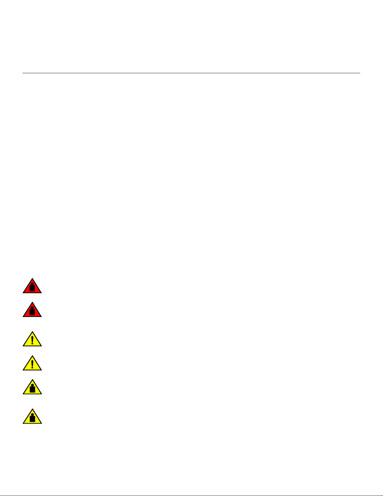
Attaching the Front Brackets
Complete the following steps to attach the front brackets to the device.
1. Position the right front bracket with the at side against the right side of the device at the front of the device, as shown in Figure
4.
2. Insert four 8-32 x 5/16-in. athead screws through the vertically aligned holes in the bracket and then into the holes on the
side of the device. Use the upper and lower screw holes, leaving the center holes empty.
3. Repeat Step 1 and Step 2 to attach the left front bracket to the left side of the device.
Brocade 7810 Extension Switch Hardware Installation Guide
7810-IG101 23
Page 24
Installing the Universal Four-Post Rack Kit (XBR-R000296)
4. Tighten all 8-32 x 5/16-in. screws to a torque of 15 in-lb (17 cm-kg).
FIGURE 4 Attaching the Front Brackets
1. Brocade Device
2. Front Brackets
3. Screws, 8-32 x 5/16-in., Flathead Phillips
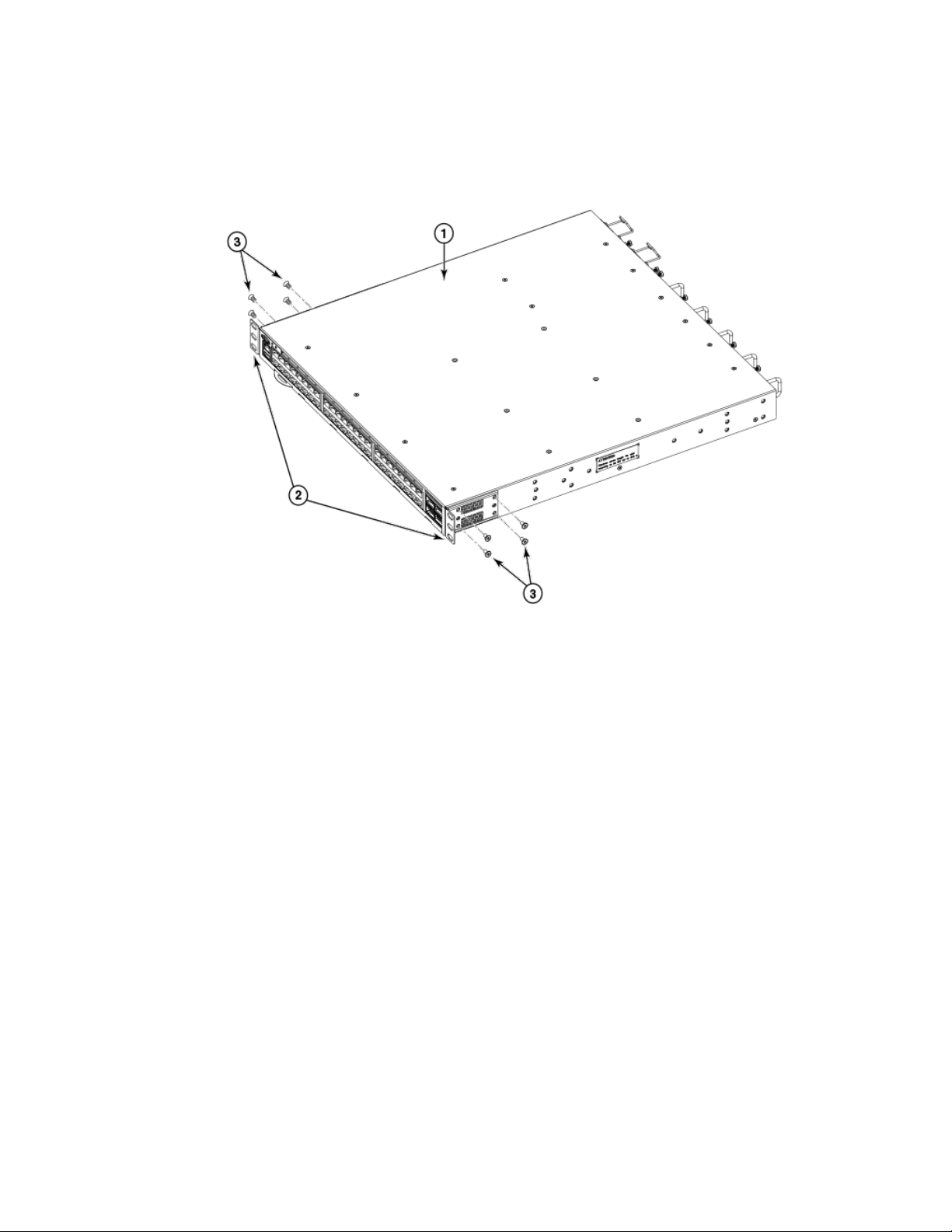
Attaching the Bracket Extensions to the Device
Complete the following steps to attach the extension brackets to the device. You can use medium and long extension brackets for this
task.
1. Select the proper length bracket extension for your rack depth.
2. Position the right bracket extension along the side of the device as shown in Figure 5.
3. Insert four 8-32 x 5/16-in. athead screws through the vertically aligned holes in the bracket extension and then into the holes
on the side of the device. Use the upper and lower screw holes, leaving the center holes empty.
4. Repeat Steps 2 and 3 to attach the left bracket extension to the left side of the device.
24 7810-IG101
Brocade 7810 Extension Switch Hardware Installation Guide
Page 25
5. Tighten all 8-32 x 5/16-in. screws to a torque of 15 in-lb (17 cm-kg).
FIGURE 5 Attaching the Bracket Extensions to the Device
Installing the Universal Four-Post Rack Kit (XBR-R000296)
1. Bracket Extension 2. Screws, 8-32 x 5/16-in., Flathead Phillips
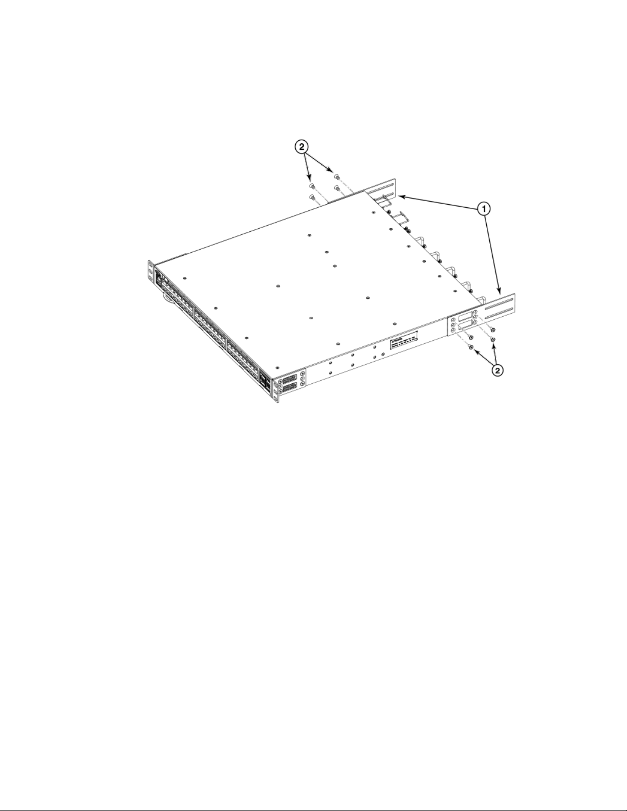
Installing the Device in the Rack
Complete the following steps to install the device in the rack.
1. Position the device in the rack, as shown in Figure 6, providing temporary support under the device the rail kit is secured to the
rack.
2. Attach the right front bracket to the right front rack post using two 10-32 x 5/8-in. panhead screws and two retainer nuts. Use
the upper and lower holes in the bracket.
Brocade 7810 Extension Switch Hardware Installation Guide
7810-IG101 25
Page 26

Installing the Universal Four-Post Rack Kit (XBR-R000296)
3. Tighten all the 10-32 x 5/8-in. screws to a torque of 25 in-lb (29 cm-kg).
FIGURE 6 Positioning the Device in the Rack
1. Screws, 10-32 x 5/8-in., Panhead Phillips 2. Retainer Nuts, 10-32
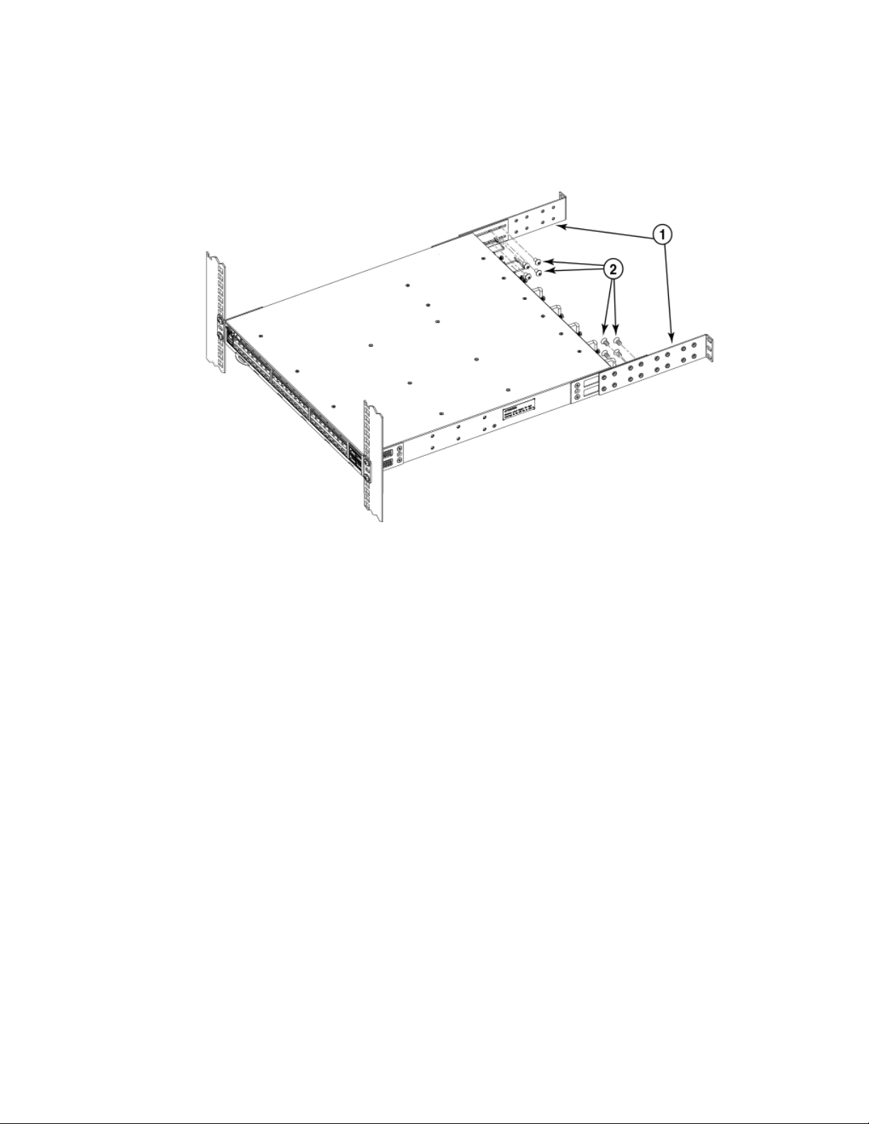
Attaching the Rear Brackets to the Extensions
Complete the following steps to attach the rear brackets to the extensions. You can use short and long rear brackets for this task. Choose
the correct bracket for the depth of your rack.
1. Select the proper length rear bracket for your rack depth.
2. Slide the right rear bracket onto the right bracket extension, as shown in the following gure.
3. Attach the brackets using four 6-32 x 1/4-in. panhead screws.
If possible, leave at least one empty vertical pair of holes between the screws for better support.
4. Repeat Step 2 and 3 to attach the left rear bracket to the left bracket extension.
26 7810-IG101
Brocade 7810 Extension Switch Hardware Installation Guide
Page 27
Installing the Universal Four-Post Rack Kit (XBR-R000296)
5. Adjust the brackets to the rack depth and tighten all 6-32 x 1/4-in. screws to a torque of 9 in-lb (10 cm-kg).
FIGURE 7 Attaching the Rear Brackets to the Extensions
1. Rear Brackets 2. Screws, 6-32 x 1/4-in., Panhead Phillips
Attaching the Rear Brackets to the Rack Posts
Complete the following steps to attach the rear brackets to the rack posts.
1. Attach the right rear bracket to the right rear rack post using two 10-32 x 5/8-in. panhead screws and two retainer nuts, as
shown in Figure 8. Use the upper and lower holes in the bracket.
2. Attach the left rear bracket to the left rear rack post using two 10-32 x 5/8-in. panhead screws and two retainer nuts. Use the
upper and lower holes in the bracket.
Brocade 7810 Extension Switch Hardware Installation Guide
7810-IG101 27
Page 28
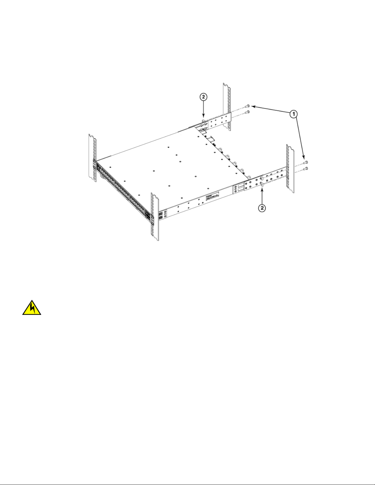
Installing the Universal Four-Post Rack Kit (XBR-R000296)
3. Tighten all 10-32 x 5/8-in. screws to a torque of 25 in-lb (29 cm-kg).
FIGURE 8 Attaching the Rear Brackets to the Rack Posts
1. Screws, 10-32 x 5/8-in., Panhead Phillips 2. Retainer Nuts, 10-32
Flush-Rear (Recessed) Mounting
The ush-rear (recessed) mounting is similar to the ush-front mounting except that the brackets are reversed on the device.
CAUTION
The device must be turned o and disconnected from the fabric during this procedure.
NOTE
The illustrations in the rack installation procedures show a 1U device, but the instructions are the same for a 2U device. The
illustrations in the rack installation procedures are for reference only and may not show the actual device.
Complete the following tasks to install the device in a four-post rack:
1. Attaching the Front Brackets to the Rear of the Device on page 29
2. Attaching the Bracket Extensions to the Front of the Device on page 29
3. Installing the Device in the Rack on page 30
4. Attaching the Rear Brackets to the Extensions at the Front of the Device on page 31
5. Attaching the Rear Brackets to the Front Rack Posts on page 33
28 7810-IG101
Brocade 7810 Extension Switch Hardware Installation Guide
Page 29

Installing the Universal Four-Post Rack Kit (XBR-R000296)
Attaching the Front Brackets to the Rear of the Device
NOTE
In this installation, the brackets are named as listed in the parts list even though the installation of the brackets is reversed from
the ush-front installation.
Complete the following steps to attach the front brackets to the rear of the device.
1. Position the right front bracket with the at side against the right rear side of the device, as shown in Figure 9.
2. Insert four 8-32 x 5/16-in. athead screws through the vertically aligned holes in the bracket and then into the holes on the
side of the device. Use the upper and lower screw holes, leaving the center holes empty.
3. Repeat Steps 1 and 2 to attach the left front bracket to the left side of the device.
4. Tighten all 8-32 x 5/16-in. screws to a torque of 15 in-lb (17 cm-kg).
FIGURE 9 Attaching the Front Brackets to the Rear of the Device
1. The Brocade Device
2. Front Brackets
3. Screws, 8-32 x 5/16-in., Flathead Phillips
Attaching the Bracket Extensions to the Front of the Device
Complete the following steps to attach the bracket extensions to the front of the device. You can use medium and long extension bracket
for this task.
1. Select the proper length extension bracket for your rack depth.
2. Position the right bracket extension along the side of the device as shown in Figure 10.
3. Insert four 8-32 x 5/16-in. athead screws through the vertically aligned holes in the bracket extension and then into the holes
on the side of the device. Use the upper and lower screw holes, leaving the center holes empty.
Brocade 7810 Extension Switch Hardware Installation Guide
7810-IG101 29
Page 30

Installing the Universal Four-Post Rack Kit (XBR-R000296)
4. Repeat Steps 2 and 3 to attach the left front bracket extension to the left side of the device.
5. Tighten all the 8-32 x 5/16-in. screws to a torque of 15 in-lb (17 cm-kg).
FIGURE 10 Attaching the Bracket Extensions to the Device
1. Extension Brackets 2. Screws, 8-32 x 5/16-in., Flathead Phillips
Installing the Device in the Rack
Complete the following steps to install the device in the rack.
1. Position the device in the rack, as shown in Figure 11, providing temporary support under the device until the rail kit is secured
to the rack.
2. Attach the right front bracket to the right rear rack post using two 10-32 x 5/8-in. panhead screws and two retainer nuts. Use
the upper and lower holes in the bracket.
30 7810-IG101
Brocade 7810 Extension Switch Hardware Installation Guide
Page 31

3. Tighten all 10-32 x 5/8-in. screws to a torque of 25 in-lb (29 cm-kg).
FIGURE 11 Positioning the Device in the Rack
Installing the Universal Four-Post Rack Kit (XBR-R000296)
1. Screws, 10-32 x 5/8-in., Panhead Phillips 2. Retainer Nuts, 10-32
Attaching the Rear Brackets to the Extensions at the Front of the Device
Complete the following steps to attach the rear brackets to the extensions. You can use short and long front brackets for this task.
1. Select the proper length rear bracket for your rack depth.
2. Slide the right rear bracket onto the right extension.
The short rear brackets are shown in Figure 12. Use the rst and third vertical pairs of holes for the screws.
See Figure 13 for the positioning of the short or long brackets and screws.
3. Attach the brackets using four 6-32 x 1/4-in. panhead screws.
4. Repeat Steps 2 and 3 to attach the left rear bracket to the left extension.
Brocade 7810 Extension Switch Hardware Installation Guide
7810-IG101 31
Page 32

Installing the Universal Four-Post Rack Kit (XBR-R000296)
5. Adjust the brackets to the rack depth and tighten all 6-32 x 1/4-in. screws to a torque of 9 in-lb (10 cm-kg).
FIGURE 12 Attaching the Rear Brackets to the Extensions at the Front of the Device
1. Rear Brackets, Short 2. Screws, 6-32 x 1/4-in., Panhead Phillips
FIGURE 13 Attaching the Short or Long Rear Brackets to the Extensions
32 7810-IG101
Brocade 7810 Extension Switch Hardware Installation Guide
Page 33

Installing the Universal Two-Post Rack Kit (XBR-R000294)
1. Rear Bracket, Short or Long 2. Screws, 6-32 x 1/4-in., Panhead Phillips
Attaching the Rear Brackets to the Front Rack Posts
Complete the following steps to attach the rear brackets to the front rack posts.
1. Attach the right rear bracket to the right front rack post using two 10-32 x 5/8-in. screws and two retainer nuts, as shown in
Figure 14. Use the upper and lower holes in the bracket.
2. Attach the left rear bracket to the left front rack post using two 10-32 x 5/8-in. screws and two retainer nuts. Use the upper and
lower holes in the bracket.
3. Tighten all 10-32 x 5/8-in. screws to a torque of 25 in-lb (29 cm-kg).
FIGURE 14 Attaching the Rear Brackets to the Front Rack Posts
1. Screws, 10-32 x 5/8-in., Panhead Phillips 2. Retainer Nuts, 10-32
Installing the Universal Two-Post Rack Kit (XBRR000294)
Use the following instructions to install a Brocade 1U or 2U device in a two-post telecommunications (Telco) rack using the Universal
Two-Post Rack Kit (XBR-R000294).
You can mount the device in a two-post rack in two ways:
• With the port side ush with the front posts
• With the posts mounted to the mid-section of the device
Brocade 7810 Extension Switch Hardware Installation Guide
7810-IG101 33
Page 34

Installing the Universal Two-Post Rack Kit (XBR-R000294)
Observe the following when mounting this device:
• Two people are required to install the device in a rack. One person should hold the device, while the other while the other screws
in the front and rear brackets.
• Before mounting your device, review any specic installation and facility requirements in the hardware installation guide for the
device.
• Hardware devices illustrated in these procedures are for reference only and may not depict the device that you are installing into
the rack.
Time and Items Required
Allow 15 to 30 minutes to complete the installation.
The following items are required to install the device using the Universal Two-Post Rack Kit:
• #2 Phillips torque screwdriver
• 1/4-inch slotted-blade torque screwdriver
Parts List
The following parts are provided with the Universal Two-Post Rack Kit (XBR-R000294).
34 7810-IG101
Brocade 7810 Extension Switch Hardware Installation Guide
Page 35

FIGURE 15 Universal Two-Post Rack Kit Parts
Installing the Universal Two-Post Rack Kit (XBR-R000294)
1. Front brackets (2)
2. Rear brackets, 3–5 inch post (2)
3. Rear brackets, 5–6 inch post (2)
4. Screw, 8-32 x 5/16-in., panhead Phillips (8)
5. Screw, 8-32 x 5/16-in., athead Phillips (16)
6. Screw, 6-32 x 1/4-in., panhead Phillips (8)
7. Screw, 10-32 x 5/8-in., panhead Phillips (8)
8. Retainer nut, 10-32 (8)
Ensure that the items listed and illustrated above are included in the kit. Note that not all parts may be used with certain installations
depending on the device type.
Flush-Front Mounting
Observe the following notes when performing this procedure:
• The device must be turned o and disconnected from the fabric during this procedure.
• The illustrations in this document show a 1U device, but the instructions are the same for a 2U device.
• The illustrations for this procedure show a two-post rack with narrow posts (3- to 5-inch) as an example.
• The illustrations in the rack installation procedures are for reference only and may not show the actual device.
CAUTION
Use the screws specied in the procedure. Using longer screws can damage the device.
Complete the following tasks to install the device in the rack:
1. Attaching the Front Brackets to the Device on page 36
2. Attaching the Front Brackets to the Rack on page 36
Brocade 7810 Extension Switch Hardware Installation Guide
7810-IG101 35
Page 36

Installing the Universal Two-Post Rack Kit (XBR-R000294)
3. Attaching the Rear Brackets to the Rack on page 37
4. Attaching the Rear Brackets to the Device on page 38
Attaching the Front Brackets to the Device
Complete the following steps to attach the front brackets to the device.
1. Position the right front bracket with the at side against the right side of the device, as shown in Figure 16.
2. Insert four 8-32 x 5/16-in. athead screws through the vertically aligned holes in the bracket and then into the holes on the
side of the device. Use the upper and lower screw holes, leaving the center holes empty.
3. Repeat Steps 1 and 2 to attach the left front bracket to the left side of the device.
4. Tighten all the 8-32 x 5/16-in. screws to a torque of 15 in-lb (17 cm-kg).
FIGURE 16 Attaching the Front Brackets
1. The Brocade Device
2. Front Brackets, Right and Left
3. Screws, 8-32 x 5/16-in., Flathead Phillips
Attaching the Front Brackets to the Rack
Complete the following steps to install the device in the rack.
1. Position the device in the rack, as shown in (Figure 17), providing temporary support under the device until the rack kit is fully
secured to the rack.
2. Attach the right front bracket to the right rack upright using two 10-32 x 5/8-in. panhead screws and two retainer nuts. Use the
upper and lower holes in the bracket.
36 7810-IG101
Brocade 7810 Extension Switch Hardware Installation Guide
Page 37

Installing the Universal Two-Post Rack Kit (XBR-R000294)
3. Attach the left front bracket to the left rack upright using two 10-32 x 5/8-in. panhead screws and two retainer nuts.
Use the upper and lower holes in the bracket.
4. Tighten all the 10-32 x 5/8-in. screws to a torque of 25 in-lb. (29 cm-kg).
FIGURE 17 Attaching the Front Brackets to the Rack
1. Screws, 10-32 x 5/8-in., Panhead Phillips 2. Retainer Nuts, 10-32
Attaching the Rear Brackets to the Rack
Complete the following steps to attach the rear brackets to the rack.
1. Select the proper length bracket for your post width. If your posts are 3 to 5 inches wide, use the brackets marked 3-5 INCH. If
your posts are 5 to 6 inches wide, use the brackets marked 5-6 INCH.
2. Position the right rear bracket in the right rear of the device, as shown in Figure 18.
3. Attach the bracket to the right rack upright using two 10-32 x 5/8-in. panhead screws and two retainer nuts. Use the upper and
lower holes in the bracket.
4. Repeat Steps 2 and 3 to attach the left rear bracket to the left rack upright.
Brocade 7810 Extension Switch Hardware Installation Guide
7810-IG101 37
Page 38

Installing the Universal Two-Post Rack Kit (XBR-R000294)
5. Tighten all the 10-32 x 5/8-in. screws to a torque of 25 in-lb. (29 cm-kg).
FIGURE 18 Attaching the Rear Brackets to the Rack
1. Retainer Nuts, 10-32
2. Rear Brackets
3. Screws, 10-32 x 5/8-in., Panhead Phillips
Attaching the Rear Brackets to the Device
Complete the following steps to attach the rear brackets to the device.
1. Align the right rear bracket to the right rear of the device and use four 8-32 x 5/16-in. panhead screws to attach the bracket to
the device, as shown in Figure 19. Be sure to insert the screws through the upper and lower slots in the bracket.
2. Align the left rear bracket to the left rear of the device and use four 8-32 x 5/16-in. panhead screws to attach the bracket to the
device. Again, use the upper and lower slots in the bracket.
38 7810-IG101
Brocade 7810 Extension Switch Hardware Installation Guide
Page 39

3. Tighten all the 8-32 x 5/16-in. screws to a torque of 15 in-lb (17 cm-kg).
FIGURE 19 Attaching the Rear Brackets to the Device
Installing the Universal Two-Post Rack Kit (XBR-R000294)
1. Screws, 8-32 x 5/16-in., Panhead Phillips
Mid-Mounting
Observe the following notes when performing this procedure:
• The device must be turned o and disconnected from the fabric during this procedure.
• The illustrations in this document show a 1U device, but the instructions are the same for a 2U device.
• The illustrations in the rack installation procedures are for reference only and may not show the actual device.
Complete the following tasks to install the device in the rack:
1. Attaching the Front Brackets to the Device on page 39
2. Attaching the Front Brackets to the Rack on page 40
3. Attaching the Rear Brackets to the Rack on page 41
4. Attaching the Rear Brackets to the Device on page 42
Attaching the Front Brackets to the Device
Complete the following steps to attach the front brackets to the device.
1. Position the right front bracket with the at side against the right side of the device, as shown in Figure 20.
Brocade 7810 Extension Switch Hardware Installation Guide
7810-IG101 39
Page 40

Installing the Universal Two-Post Rack Kit (XBR-R000294)
2. Insert four 8-32 x 5/16-in. athead screws through the vertically aligned holes in the bracket and then into the holes on the
side of the device. Use the upper and lower screw holes, leaving the center holes empty.
3. Repeat Steps 1 and 2 to attach the left front bracket to the left side of the device.
4. Tighten all 8-32 x 5/16-in. screws to a torque of 15 in-lb (17 cm-kg).
FIGURE 20 Attaching the Front Brackets
1. The Brocade Device
2. Front Brackets, Right and Left
3. Screws, 8-32 x 5/16-in., Flathead Phillips
Attaching the Front Brackets to the Rack
Complete the following steps to install the device in the rack.
1. Position the device in the rack, as shown in Figure 21, providing temporary support under the device until the rack kit is fully
secured to the rack.
2. Attach the right front bracket to the right rack upright using two 10-32 x 5/8-in. screws and two retainer nuts. Use the upper
and lower holes in the bracket.
3. Attach the left front bracket to the left rack upright using two 10-32 x 5/8-in. screws and two retainer nuts. Use the upper and
lower holes in the bracket.
40 7810-IG101
Brocade 7810 Extension Switch Hardware Installation Guide
Page 41

4. Tighten all the 10-32 x 5/8-in. screws to a torque of 25 in-lb (29 cm-kg).
FIGURE 21 Attaching the Front Brackets to the Rack
Installing the Universal Two-Post Rack Kit (XBR-R000294)
1. Screws, 10-32 x 5/8-in., Panhead Phillips 2. Retainer Nuts, 10-32
Attaching the Rear Brackets to the Rack
Complete the following steps to attach the rear brackets to the rack.
1. Select the proper length bracket for your post width. If your posts are 3 to 5 inches wide, use the brackets marked 3-5 INCH. If
your posts are 5 to 6 inches wide, use the brackets marked 5-6 INCH.
2. Position the right rear bracket in the right rear of the device, as shown in the following gure. Whether you are using the 3-5 inch
or the 5-6 inch bracket, the rear end of the bracket will be ush with the back of the device.
3. Attach the brackets to the right rack upright using two 10-32 x 5/8-in. panhead screws and two retainer nuts.
4. Repeat Step 2 and Step 3 to attach the left rear bracket to the left rack upright.
Brocade 7810 Extension Switch Hardware Installation Guide
7810-IG101 41
Page 42

Installing the Universal Two-Post Rack Kit (XBR-R000294)
5. Tighten all the 10-32 x 5/8-in. screws to a torque of 25 in-lb (29 cm-kg).
FIGURE 22 Attaching the Rear Brackets to the Rack
1. Retainer Nuts, 10-32
2. Rear Brackets (Right and Left)
3. Screws, 10-32 x 5/8-in., Panhead Phillips
Attaching the Rear Brackets to the Device
Complete the following steps to attach the rear brackets to the device.
1. Align the right rear bracket to the right rear of the device and use four 8-32 x 5/16-in. panhead screws to attach the bracket to
the device, as shown in Figure 23. Be sure to insert the screws through the upper and lower slots in the bracket.
2. Align the left rear bracket to the left rear of the device and use four 8-32 x 5/16-in. panhead screws to attach the bracket to the
device. Again, use the upper and lower slots in the bracket.
42 7810-IG101
Brocade 7810 Extension Switch Hardware Installation Guide
Page 43

3. Tighten all the 8-32 x 5/16-in. screws to a torque of 15 in-lb (17 cm-kg).
FIGURE 23 Attaching the Rear Brackets to the Device
Installing the Universal Two-Post Rack Kit (XBR-R000294)
1. Screws, 8-32 x 5/16-in., Panhead Phillips
Brocade 7810 Extension Switch Hardware Installation Guide
7810-IG101 43
Page 44

Initial Setup and Verication
• Items Required....................................................................................................................................................................................................44
• Providing Power to the Device.....................................................................................................................................................................44
• Establishing a First-Time Serial Connection.......................................................................................................................................... 45
• Conguring the IP Address...........................................................................................................................................................................46
• Setting the Date and Time.............................................................................................................................................................................46
• Customizing the Chassis Name and Switch Name............................................................................................................................ 48
• Establishing an Ethernet Connection........................................................................................................................................................ 48
• Setting the Domain ID.....................................................................................................................................................................................49
• Verifying Correct Operation...........................................................................................................................................................................49
• Backing Up the Conguration......................................................................................................................................................................51
• Powering Down the Device........................................................................................................................................................................... 51
Items Required
The following items are required for initial setup and verication of the device:
• The device, mounted and installed with the required power supply and fan assemblies, transceivers, and cables; and connected
to a power source.
• A workstation computer with a terminal emulator application installed, such as PuTTY, XShell, or SecureCRT on Windows.
• An unused IP address with a corresponding subnet mask and gateway address.
• A serial cable with an RJ-45 connector.
• An Ethernet cable.
• Access to an FTP server or USB device for backing up (uploading) or downloading the device conguration (optional).
Providing Power to the Device
Perform the following steps to provide power to the device.
1. Connect the power cords to both power supplies, and then to power sources on separate circuits to protect against power
failure. Ensure that the power cords have a minimum service loop of 6 inches available and are routed to avoid stress.
2. Power on the power supplies by ipping both switches to the on position (the "I" symbol). The power supply LEDs display
amber until the power-on self-test (POST) is complete, and then the LEDs change to green. The switch usually requires several
minutes to boot and complete the POST.
NOTE
Power is supplied to the device as soon as the rst power supply is connected and turned on.
3. After the POST is complete, verify that the switch power and switch status LEDs are green.
For more information about how to interpret the POST, BOOT, and diagnostics tests, refer to Monitoring the Device on page
59.
44 7810-IG101
Brocade 7810 Extension Switch Hardware Installation Guide
Page 45

Establishing a First-Time Serial Connection
Establishing a First-Time Serial Connection
Perform the following steps to log in to the device through a serial connection.
1. Connect the serial cable to the serial port on the device and to an RS-232 serial port on the workstation.
If the serial port on the workstation is RJ-45 instead of RS-232, remove the adapter on the end of the serial cable and insert
the exposed RJ-45 connector into the RJ-45 serial port on the workstation.
2. Disable any serial communication programs running on the workstation such as synchronization programs.
3. Open a terminal emulator application such as PuTTY, XShell, or SecureCRT on a Windows PC, or TERM, TIP, or C-Kermit in a
Linux environment, and congure the application as follows:
• In a Windows environment, use the following values:
Parameter Value
Bits per second 9600
Databits 8
Parity None
Stop bits 1
Flow control None (must be disabled on the host side)
NOTE
Flow control is not supported on the serial connection when attached to a remote terminal and must be disabled
on the customer-side remote terminal server in addition to the host-side clients.
• In a UNIX environment using TIP, enter the following string at the prompt:
tip /dev/ttyb -9600
If ttyb is already in use, use ttya instead and enter the following string at the prompt:
tip /dev/ttya -9600
4. When the terminal emulator application stops reporting information, press Enter to display the login prompt.
Switch Console Login:
5. Log on to the device as admin, using the default password (password). You are prompted to change the default user name and
password at initial login. Make sure to write down the new credentials and keep this information in a secure location.
Fabric OS (swDir)
swDir login: admin
Password:
Please change your passwords now.
Use Control-C to exit or press 'Enter' key to proceed.
swDir:admin>
6. Modify the credentials. To cancel, press Ctrl+C.
NOTE
Initial passwords can be 8 to 40 characters long. They must begin with an alphabetic character. They can include
numeric characters, the period (.), and the underscore (_) only. Passwords are case-sensitive, and they are not
displayed when you enter them on the command line.
Brocade 7810 Extension Switch Hardware Installation Guide
7810-IG101 45
Page 46

Conguring the IP Address
Conguring the IP Address
You can congure the device with a static IP address, or you can use a Dynamic Host Conguration Protocol (DHCP) server to set the IP
address of the switch. DHCP is enabled by default. The device supports both IPv4 and IPv6 addresses.
Using DHCP to Set the IP Address
When using DHCP, the switch obtains its IP address, subnet mask, and default gateway address from the DHCP server. The DHCP
client can connect only to a DHCP server that is on the same subnet as the switch. If your DHCP server is not on the same subnet as the
switch, use a static IP address.
Setting a Static IP Address
To set a static IP address for the device, complete the following steps.
1. Log in to the device as admin.
2. Use the ipaddrset command to set the Ethernet IP address.
• If you are going to use an IPv4 address, enter the IP address in dotted decimal notation as prompted.
Ethernet IP Address: [192.168.74.102]
• If you are going to use an IPv6 address, enter the network information in colon-separated notation as prompted.
device:admin> ipaddrset -ipv6 --add 1080::8:800:200C:417A/64
IP address is being changed...Done.
3. Complete the rest of the network information as prompted. (IPv4 format shown):
Ethernet Subnetmask: [255.255.255.0]
Ethernet IP Address: [192.168.74.102]
Gateway IP Address: [192.168.74.1]
4. Enter o to disable DHCP when prompted.
DHCP [OFF]: off
Setting the Date and Time
The date and time settings are used for logging events, error detection, and troubleshooting. However, device operation does not depend
on the date and time; a device with incorrect date or time values still functions properly.
You can synchronize the local time of the principal or primary fabric conguration server (FCS) device to that of an external Network Time
Protocol (NTP) server.
Perform the following steps to set the date and time.
1. Log in to the device as admin.
46 7810-IG101
Brocade 7810 Extension Switch Hardware Installation Guide
Page 47

Setting the Date and Time
2. Enter the date newdate command at the command line.
The newdate variable species the new date and time enclosed in double quotation marks. The operand is optional; if omitted,
the current date and time are displayed. Date and time are specied as a string in the mmddhhmmyy format:
• mm: Species the month. Valid values are 01 to 12.
• dd: Species the date. Valid values are 01 to 31.
• hh: Species the hour. Valid values are 00 to 23.
• mm: Species the minutes. Valid values are 00 to 59.
• yy: Species the year, valid values are 00 to 37 and 70 to 99. Year values from 70 to 99 are interpreted as 1970 to
1999; year values from 00 to 37 are interpreted as 2000 to 2037.
device:admin> date
Thu Dec 22 14:05:10 UTC 2016
device:admin> date "1222150617"
Thu Dec 22 15:06:00 UTC 2017
Setting the Time Zone
The default time zone is Coordinated Universal Time (UTC). The time zone must be set only once because the value is stored in
nonvolatile memory. Use the following procedure to set the time zone.
1. Log in as admin.
2. Use the tsTimeZone --interactive command and follow the prompts, or enter the tsTimeZone[houroset,minuteoset] command as follows:
For Pacic Standard Time, enter tsTimeZone -8,0.
For Central Standard Time, enter tsTimeZone -6,0.
For Eastern Standard Time, enter tsTimeZone -5,0.
TABLE 8 tsTimeZone Command Parameter Selection for the U.S. tTme Zones
Local Time tsTimeZone Parameter (Dierence from UTC)
Atlantic Standard -4,0
Atlantic Daylight -3,0
Eastern Standard -5,0
Eastern Daylight -4,0
Central Standard -6,0
Central Daylight -5,0
Mountain Standard -7,0
Mountain Daylight -6,0
Pacic Standard -8,0
Pacic Daylight -7,0
Alaskan Standard -9,0
Alaskan Daylight -8,0
Hawaiian Standard -10,0
Brocade 7810 Extension Switch Hardware Installation Guide
7810-IG101 47
Page 48

Customizing the Chassis Name and Switch Name
Synchronizing the Local Time with an External Source
Perform the following steps to synchronize the local time of the principal or primary FCS device with that of an external NTP server.
1. Log in as admin.
2. Enter the tsClockServer-ipaddr command.
The ipaddr variable represents the IP address of the NTP server that the device can access. This variable is optional; by default,
the value is "LOCL".
switch:admin> tsclockserver 192.168.126.60
Updating Clock Server configuration...done.
Updated with the NTP servers
Customizing the Chassis Name and Switch Name
Changing the chassis and switch names is important for uniquely distinguishing and identifying the device uniquely and for accurate
tracking of logs and errors. The messages that appear in the log are labeled with the switch name or chassis name, which makes tracking
the errors much easier. Specify an easily understandable and meaningful name for the chassis and switch names.
Perform the following steps to change the chassis name and then the switch name.
1. Log in to the device through Telnet using the admin account.
2. Change the chassis name by using the chassisName command.
device:admin> chassisname Chassis_001
3. Change the switch name by using the switchName command.
device:admin> switchname Switch_001
Committing configuration...
Done
Switch name has been changed. Please re-login to the switch for the change to applied
Establishing an Ethernet Connection
Perform the following steps to establish an Ethernet connection to the device.
1. Remove the plug from the Ethernet port.
2. Connect an Ethernet cable to the device Ethernet port and to the workstation or to an Ethernet network that connects the
workstation.
NOTE
At this point, the device can be accessed remotely, using either the command line or Brocade Web Tools. Ensure that
the device is not being modied from any other connections during the remaining tasks in this chapter. The Ethernet
management port also supports Auto MDI/MDIX.
48 7810-IG101
Brocade 7810 Extension Switch Hardware Installation Guide
Page 49

Setting the Domain ID
Perform the following steps to set the switch domain ID.
1. Log in to the switch through Telnet using the admin account.
2. Modify the domain ID if required.
The default domain ID is 1. If the switch is not powered on until after it is connected to the fabric and the default domain ID is
already in use, the domain ID for the new switch is automatically reset to a unique value. If the switch is connected to the fabric
after it has been powered on and the default domain ID is already in use, the fabric segments. To nd the domain IDs that are
currently in use, enter the fabricShow command on another switch in the fabric.
Perform the following steps to modify the domain ID.
a) Disable the switch by entering the switchDisable command.
b) Enter the configure command. The command prompts display sequentially; enter a new value or press Enter to accept
each default value.
c) Enter y after the Fabric param prompt.
Fabric param (yes, y, no, n): [no] y
Verifying Correct Operation
d) Enter a unique domain ID (such as the domain ID used by the previous switch, if still available).
Domain: (1..239) [1] 3
e) Complete the remaining prompts or press Ctrl+D to accept the remaining settings without completing all the prompts.
f) Re-enable the switch by entering the switchEnable command.
Verifying Correct Operation
Perform the following steps to verify correct operation of the device.
1. Check the LEDs to verify that all components are functional.
Brocade 7810 Extension Switch Hardware Installation Guide
7810-IG101 49
Page 50

Verifying Correct Operation
2. Verify the correct operation of the device by entering the following commands from the workstation.
Command Description
psShow
fanShow
switchShow
tempShow
historyShow
errDump
Displays the power supply status and information.
Displays the fan status and information.
Displays the switch status and information.
Displays the temperature status and information.
Displays the device history.
Displays any errors.
The switchShow command provides the following information about the device and ports status.
ras210:admin> switchshow
witchName: ras210
switchType: 178.0
switchState: Online
switchMode: Native
switchRole: Subordinate
switchDomain: 210
switchId: fffec2
switchWwn: 10:00:44:18:71:47:ff:e6
zoning: ON (WB_RAS159_32G_LSAN)
switchBeacon: OFF
FC Router: OFF
HIF Mode: OFF
LS Attribute: [Inherited FID: 128]
Index Port Address Media Speed State Proto
==================================================
0 0 010000 id N16 Online FC F-Port 10:00:8c:7c:ff:5f:42:00
1 1 010100 id N16 Online FC F-Port 10:00:8c:7c:ff:5f:42:01
2 2 010200 -- N32 No_Module FC (POD license not assigned or reserved yet)
3 3 010300 -- N32 No_Module FC (POD license not assigned or reserved yet)
4 4 010400 -- N32 No_Module FC (POD license not assigned or reserved yet)
5 5 010500 -- N32 No_Module FC (POD license not assigned or reserved yet)
6 6 010600 -- N32 No_Module FC (POD license not assigned or reserved yet)
7 7 010700 -- N32 No_Module FC (POD license not assigned or reserved yet)
8 8 010800 -- N32 No_Module FC (POD license not assigned or reserved yet)
9 9 010900 -- N32 No_Module FC (POD license not assigned or reserved yet)
10 10 010a00 -- N32 No_Module FC (POD license not assigned or reserved yet)
11 11 010b00 -- N32 No_Module FC (POD license not assigned or reserved yet)
12 12 010c00 -- -- Offline VE
13 13 010d00 -- -- Offline VE
14 14 010e00 -- -- Offline VE
15 15 010f00 -- -- Offline VE
ge0 id 1G Offline FCIP Copper Disabled (Unsupported blade mode)
ge1 id 1G Offline FCIP Copper Disabled (Unsupported blade mode)
ge2 id 1G No_Light FCIP
ge3 id 1G No_Light FCIP
ge4 id 1G No_Light FCIP
ge5 id 1G No_Light FCIP
ge6 id 1G No_Sync FCIP
ge7 id 1G No_Sync FCIP
<Output truncated>
50 7810-IG101
Brocade 7810 Extension Switch Hardware Installation Guide
Page 51

Powering Down the Device
Backing Up the Conguration
Brocade recommends backing up the conguration on a regular basis to ensure that a complete conguration is available for
downloading to a replacement switch.
1. Log in to the device as the admin user.
2. Back up the device conguration to an FTP server by entering the configUpload command and following the prompts.
sb_70:admin> configupload
Protocol (scp, ftp, local) [ftp]:
Server Name or IP Address [host]: 192.168.0.100
User Name [user]: anonymous
Path/Filename [<home dir>/config.txt]: /dumps/supportsave/pz/switch85/G20-1.txt
Section (all|chassis|switch [all]): all
configUpload complete: All selected config parameters are uploaded
This command uploads the device conguration to the server, making it available for downloading to a replacement device if
necessary.
NOTE
If Virtual Fabrics (VF) is enabled, you must enter configUpload for each VF separately.
Powering Down the Device
Complete the following steps to power down the device.
NOTE
All devices are returned to their initial state the next time the switch is powered on.
1. Shut down the Fabric OS software using the sysShutdown command.
2. Identify the power-on switches in the nonport-side of the device.
3. Power o both power supplies by setting each power switch to the “O” position.
NOTE
Setting the power switch to o (O) position will shut down the power supply but not the fans in a power supply and fan
assembly. Also, removing the AC power cables does not shut down the fans.
4. Unplug the power cables from the power source before servicing the device or FRUs.
Brocade 7810 Extension Switch Hardware Installation Guide
7810-IG101 51
Page 52

Installing Transceivers and Cables
• Time and Items Required...............................................................................................................................................................................52
• Precautions Specic to Transceivers and Cables.................................................................................................................................53
• Cleaning the Fiber-Optic Connectors.......................................................................................................................................................53
• Managing Cables...............................................................................................................................................................................................53
• Installing an SFP+ Transceiver..................................................................................................................................................................... 54
• Replacing an SFP+ Transceiver................................................................................................................................................................... 56
• Verifying the Operation of New Transceivers.........................................................................................................................................58
Time and Items Required
The installation or replacement procedure for one transceiver takes less than 5 minutes. Ensure that the following items are available:
• Required number of compatible power cables
• Required number of supported Brocade-branded transceivers
For current information on qualied transceivers supported by this device, refer to the "Brocade Fibre Channel Transceiver
Platform Support Matrix" and applicable transceiver data sheets on www.broadcom.com.
DANGER
Use only optical transceivers that are qualied by Brocade Communications Systems LLC and comply with the
FDA Class 1 radiation performance requirements dened in 21 CFR Subchapter I, and with IEC 60825 and
EN60825. Optical products that do not comply with these standards might emit light that is hazardous to the
eyes.
• Required number of compatible ber-optic cables
• Optical transceiver extraction tool
NOTE
Many Brocade switches, backbones, and directors come with a transceiver extraction tool and holster. The extraction
tool is designed to remove transceivers from modules where the space is limited. If you did not receive this tool with
your product, you can order it from Brocade using part number XBR-48000-R0129.
FIGURE 24 Optical Transceiver Extraction Tool
52 7810-IG101
Brocade 7810 Extension Switch Hardware Installation Guide
Page 53

Precautions Specic to Transceivers and Cables
DANGER
All ber-optic interfaces use Class 1 lasers.
DANGER
Use only optical transceivers that are qualied by Brocade Communications Systems LLC and comply with the FDA
Class 1 radiation performance requirements dened in 21 CFR Subchapter I, and with IEC 60825 and EN60825. Optical
products that do not comply with these standards might emit light that is hazardous to the eyes.
CAUTION
Before plugging a cable into any port, be sure to discharge the voltage stored on the cable by touching the electrical
contacts to ground surface.
Cleaning the Fiber-Optic Connectors
Managing Cables
To avoid problems with the connection between the ber-optic transceiver (SFP+ or QSFP) and the ber cable connectors, Brocade
strongly recommends cleaning both connectors each time you disconnect and reconnect them. Dust can accumulate on the connectors
and cause problems such as reducing the optic launch power.
To clean the ber cable connectors, Brocade recommends using a ber-optic reel-type cleaner. When not using an SFP+, or QSFP
connector, make sure to keep the protective covering in place.
Managing Cables
The minimum bend radius for a 50-micron cable is 2 inches under a full tensile load and 1.2 inches with no tensile load. Cables can be
organized and managed in a variety of ways, for example, using cable channels on the sides of the rack or patch panels to minimize
cable management. Follow these recommendations:
NOTE
You should not use tie wraps with optical cables because they are easily overtightened and can damage the optic bers.
CAUTION
Before plugging a cable into any port, be sure to discharge the voltage stored on the cable by touching the electrical
contacts to ground surface.
• Plan for the proper rack space required for cable management before installing the switch.
• Leave at least 1m (3.28 ft) of slack for each port cable. This slack provides room to remove and replace the switch, allows for
inadvertent movement of the rack, and helps prevent the cables from being bent to less than the minimum bend radius.
• If you are using Brocade ISL Trunking, consider grouping cables by trunking groups. The cables used in trunking groups must
meet specic requirements, as described in the Brocade Fabric OS Administratorion Guide .
• For easier maintenance, label the ber-optic cables and record the devices to which they connect.
• Keep LEDs visible by routing port cables and other cables away from the LEDs.
• Use hook and loop style straps to secure and organize ber-optic cables.
Brocade 7810 Extension Switch Hardware Installation Guide
7810-IG101 53
Page 54

Installing an SFP+ Transceiver
Installing an SFP+ Transceiver
This switch supports only Brocade-qualied transceivers. For current information on qualied transceivers supported by this device, refer
to the "Brocade Fibre Channel Transceiver Platform Support Matrix" and applicable transceiver data sheets on www.broadcom.com. If
you use an unqualied transceiver, the switchshow command output shows the port in a Mod_Inv state. Fabric OS also logs the issue in
the system error log.
To insert an SFP+ transceiver, complete the following steps:
54 7810-IG101
Brocade 7810 Extension Switch Hardware Installation Guide
Page 55

Installing an SFP+ Transceiver
NOTE
The 16 and 32Gb/s SFP+ transceivers do not have bails. Always use the pull tab to insert or remove the transceivers, since the
SFP might be hot.
1. Perform one of the following steps, depending on your transceiver type.
• If the transceiver has a pull tab (16 and 32Gb/s SFP+ transceivers), use a pull tab to help push the transceiver into the port
until it is rmly seated and the latching mechanism clicks.
FIGURE 25 Installing an SFP+ Transceiver with Pull Tab into a Port
1. Pull Tab 2. Transceiver
• If the transceiver has a bail latch mechanism (10GbE transceivers), ensure that the bail (wire handle) is in the unlocked
position, grasp the transceiver, and push it into the port until rmly seated. Close the bail to latch the transceiver in the slot.
FIGURE 26 Installing an SFP+ Transceiver with a Bail Latch into a Port
1. Bail
Brocade 7810 Extension Switch Hardware Installation Guide
7810-IG101 55
Page 56

Replacing an SFP+ Transceiver
Transceivers are keyed so that they can only be inserted only with the correct orientation. If a transceiver does not slide in easily,
ensure that it is correctly oriented.
2. Position a cable so that the key (the ridge on one side of the cable connector) is aligned with the slot in the transceiver. Insert the
cable into the transceiver until the latching mechanism clicks.
NOTE
Cables are keyed so that they can be inserted in only one way. If a cable does not slide in easily, ensure that it is
correctly oriented. Do not insert any unsupported cable intended for another type of transceiver into a regular SFP+
transceiver. You may damage the cable and the transceiver.
Replacing an SFP+ Transceiver
Complete the following steps to remove an SFP+ transceiver and install a new one.
NOTE
16 and 32Gb/s SFP+ transceivers have pull tabs instead of bails. Always use the pull tab to insert or remove SFP+
transceivers, as the SFP might be hot.
1. Remove any cables that are inserted into the transceiver.
56 7810-IG101
Brocade 7810 Extension Switch Hardware Installation Guide
Page 57

Replacing an SFP+ Transceiver
2. Remove the transceiver by performing one of the following steps, depending on your transceiver type.
• If the transceiver has a pull tab (16b and 32Gb/s SFP+ transceivers), grasp the pull tab and pull the transceiver straight out
from the port.
NOTE
Grasp the pull tab near the body of the transceiver to reduce the chances of bending the pull tab. Since the
transceiver may be hot, avoid touching it.
FIGURE 27 Replacing an SFP+ Optical Transceiver with a Pull Tab into a Port
1. Pull Tab 2. Transceiver
• If transceiver has a bail latch mechanism (10GbE transceivers), unlatch the transceiver from the port by pulling the bail (wire
handle) away from its pivot point using your ngers or the hooked end of the transceiver extraction tool. Pull the transceiver
out from the port slightly using the bail, and then gasp the transceiver with your ngers and slide it straight out of the port.
FIGURE 28 Installing an SFP+ Transceiver with a Bail Latch into a Port
1. Bail
Brocade 7810 Extension Switch Hardware Installation Guide
7810-IG101 57
Page 58

Verifying the Operation of New Transceivers
3. To install the transceiver, perform one of the following steps depending on your transceiver type:
• If the transceiver has a pull tab (16- and 32-Gb/s SFP+ transceivers), use the pull tab to help push the transceiver into the
port until it is rmly seated and the latching mechanism clicks.
• If the transceiver has a bail latch mechanism (10GbE transceivers), ensure that the bail (wire handle) is in the unlocked
position, grasp the transceiver, and push it into the port until rmly seated. Close the bail to latch the transceiver in the slot.
Transceivers are keyed so that they can be inserted only with the correct orientation. If a transceiver does not slide in easily,
ensure that it is correctly oriented.
4. Position a cable so that the key (the ridge on one side of the cable connector) is aligned with the slot in the transceiver. Insert the
cable into the transceiver until the latching mechanism clicks.
Cables are keyed so that they can be inserted in only one way. If a cable does not slide in easily, ensure that it is correctly
oriented.
Verifying the Operation of New Transceivers
You can use the following commands to verify if the transceivers are working correctly:
errDump
•
fabricShow
•
sfpShow
•
switchShow
•
Refer to the Brocade Fabric OS Command Reference for output examples and descriptions.
58 7810-IG101
Brocade 7810 Extension Switch Hardware Installation Guide
Page 59

Monitoring the Device
• Interpreting Port-Side LEDs.........................................................................................................................................................................59
• Interpreting Nonport-Side LEDs.................................................................................................................................................................62
• Interpreting POST Results.............................................................................................................................................................................63
• Interpreting BOOT Results............................................................................................................................................................................63
• Running Diagnostic Tests...............................................................................................................................................................................64
Interpreting Port-Side LEDs
System activity and status can be determined through the activity of the LEDs on the switch. There are three possible LED states for
switch power, FC ports, and GbE ports: no light, a steady light, and a ashing light. Flashing lights may be slow, fast, or ickering. The
lights are green or amber. Sometimes, the LEDs may ash either of the colors during boot, POST, or other diagnostic tests. This is
normal; it does not indicate a problem unless the LEDs do not indicate a healthy state after all boot processes and diagnostic tests are
complete.
The following illustration identies port-side power and port status LEDs.
FIGURE 29 LEDs on the Port-Side of the Switch
1. System Power LED
2. System Status LED
3. Ethernet Management Port Link Status LED
4. Ethernet Management Port Link Activity LED
5. FC (16 or 32Gb/s) SFP+ Port Status LED
6. 1GbE RJ-45 Copper Port Link Status LED
7. 1GbE RJ-45 Copper Port Link Activity LED
8. 1 or 10GbE SFP+ Port Status LED
System Power LED
See the following table to interpret the system power LED.
TABLE 9
LED Color Status of Hardware Recommended Action
No light The system is o or there is an internal power
Brocade 7810 Extension Switch Hardware Installation Guide
7810-IG101 59
System Power LED Patterns During Normal Operation
supply failure.
Verify that the system is powered on, that the
power cables are attached, and that your power
source is live.
Page 60

Interpreting Port-Side LEDs
TABLE 9 System Power LED Patterns During Normal Operation (continued)
LED Color Status of Hardware Recommended Action
If the system power LED is not green, the unit
may be faulty.
Contact your solution provider.
Steady green The system is on and power supplies are
functioning properly.
No action is required.
System Status LED
See the following table to interpret the system status LED.
TABLE 10 System Status LED patterns During Normal Operation
LED Color Status of Hardware Recommended Action
No light The system is o or there is no power. Verify that the system is on and has completed
booting.
Steady green The POST and initialization have completed. The
system is on and functioning properly.
Steady amber (for more than 5 seconds—can
take over a minute to complete the POST)
Steady amber (for more than a few minutes) Unknown state, boot failed, or the system is
Flashing amber/green Attention is required. A number of variables can
System is going through the power-up process. No action is required.
faulty.
NOTE
Once the POST completes and the
switch has failed, a steady amber
color may result.
cause this status, including a single power
supply failure, a fan failure, or one or more
environmental ranges being exceeded.
No action is required.
Perform the following steps:
1. Connect a serial cable to the system.
2. Reboot the system.
3. Check the failure indicated on the
system console
4. Contact your solution provider.
Check the management interface and the error
log for details on the cause of the status.
Contact your solution provider.
Ethernet Management Port Link Status and Activity LEDs
See the following table to interpret the Ethernet management port status and activity LEDs.
• The status LED is the leftmost LED under the port.
• The activity LED is the rightmost LED under the port.
TABLE 11 Management Port Link Status LED Patterns During Normal Operation
LED Status of Hardware Recommended Action
No light (LED is o) The Ethernet link speed is 10/100Mb/s or the
link is not established.
Green (LED is on) The Ethernet link speed is 1000Mb/s.
The Ethernet link is healthy and trac is owing
through the port.
60 7810-IG101
Ensure that the switch has power.
No action is required.
Brocade 7810 Extension Switch Hardware Installation Guide
Page 61

Interpreting Port-Side LEDs
TABLE 12 Management Port Link Activity LED Patterns During Normal Operation
LED Color Status of Hardware Recommended Action
No light (LED is o) No activity is present on the link. Ensure that the switch has power, that the
Ethernet cable is rmly seated, and that the
connected device is functioning.
Blinking green Activity is present on link. No action is required.
FC Port Status LED
See the following table to interpret the FC port status LEDs.
TABLE 13 FC Port Status LED Patterns During Normal Operation
LED Color Status of Hardware Recommended Action
No light Indicates one of the following:
• No signal or light carrier (media or
cable) detected.
• The device may be currently
initializing.
• The connected device is congured in
an oine state.
Steady green The port is online (connected to an external
device) but has no trac.
Slow-ashing green (on 1 for second; then o
for 1 second)
Fast-ashing green (on for 1/4 second; then o
for 1/4 second)
Flickering green The port is online, and frames are owing
Steady amber The port is receiving light or signal carrier, but it
Slow-ashing amber (on for 2 seconds; then o
for 2 seconds)
Fast-ashing amber (on for 1/2 second; then o
for 1/2 second)
The p;ort is online but is segmented because of
a loopback cable or incompatible device
connection.
the port is online, and an internal loopback
diagnostic test is running.
through the port.
is not online yet.
The port is disabled because of diagnostics or
the portDisable command.
The SFP+ or port is faulty. Reset the port.
• Verify that the power LED is on, and
check the SFP+ and cable.
• Verify that the device is not currently
being initialized.
• Verify the status of the connected
device.
No action is required.
Verify that the correct device is attached to the
switch.
No action is required.
No action is required.
No action is required.
Reset the port.
The portCfgPersistentDisable command is
persistent across reboots.
Replace the SFP+. Must be a Brocade-branded
SFP+.
GbE Port Status LEDs
See the following tables to interpret the GbE port status LEDs.
TABLE 14
LED Color Status of Hardware Recommended Action
(Link status LED) — No light No link is available. Verify that the switch power LED is on; check the
(Link status LED) — Steady green There is a link. No action is required.
(Link activity LED) — No light There is no activity (trac). No action is required.
(Link activity LED) — Blinking green There is link activity (trac). No action is required.
Brocade 7810 Extension Switch Hardware Installation Guide
7810-IG101 61
1GbE RJ-45 Status LED Patterns During Normal Operation
cable connection.
Page 62

Interpreting Nonport-Side LEDs
TABLE 15 1GbE/10GbE SFP+ Port Status LED Patterns During Normal Operation
LED Color Status of Hardware Recommended Action
No light No link is available. Verify that the switch power LED is on; check the
cable connection.
Steady green There is a link. No action is required.
Blinking green There is link activity (trac). No action is required.
Steady amber The SFP+ or port is faulty. Reset the port.
Replace the SFP+. Must be a Brocade-branded
SFP+.
Interpreting Nonport-Side LEDs
Each eld-replaceable power supply and fan assembly unit contains a status LED.
FIGURE 30 Nonport-Side LEDs with AC Power Supplies
1. Power Supply and Fan Assembly 2
2. Power Supply and Fan Assembly 1
3. Power Supply and Fan Assembly 1 Status LED
4. Power Supply and Fan Assembly 2 Status LED
Power Supply and Fan Assembly Status LED
See the following table to interpret the power supply and fan assembly status LED during normal operation.
TABLE 16 Power Supply and Fan Assembly Status LED Patterns During Normal Operation
LED Color Description Action Required
No light The power supply and fan assembly is not
receiving power, or is o.
Steady green The power supply and fan assembly is operating
normally.
Flashing green (for more than 5 seconds) The power supply and fan assembly is faulty for
one of the following reasons:
• The assembly is switched o (ashing
for ~ 5 seconds, then o).
• The power cable is disconnected
(ashing for ~ 5 seconds, then o).
• The power supply and fan assembly
has failed.
Verify that the power supply and fan assembly is
on and seated and that the power cord is
connected to a functioning power source.
No action is required.
Try one of the following:
• Check the power cable connection.
• Verify that the assembly is powered
on.
• Replace the power supply and fan
assembly.
62 7810-IG101
Brocade 7810 Extension Switch Hardware Installation Guide
Page 63

Interpreting BOOT Results
TABLE 16 Power Supply and Fan Assembly Status LED Patterns During Normal Operation (continued)
LED Color Description Action Required
NOTE: When the device is rst powered on, the
power supply and fan assembly status LED
ashes until the POST has completed.
Interpreting POST Results
Each time the switch is powered on, rebooted, or reset, the switch performs a power-on self-test (POST). The total boot time with the
POST can be several minutes. The POST can be omitted after subsequent reboots by using the fastboot command or entering the
diagDisablePost command to persistently disable the POST. The success or failure results of the diagnostic tests that run during
POST can be monitored through LED activity, the error log, or the command line interface. During the POST, the LEDs ash dierent
colors.
The POST performs the following tasks:
• Conducts preliminary POST diagnostics.
• Initializes the operating system.
• Initializes thehardware.
• Runs diagnostic tests on several functions, including the circuitry, port functionality, memory, statistics counters, and
serialization.
Perform the following steps to determine whether the POST completed successfully and whether any errors were detected.
1. Verify that the LEDs on the device indicate that all components are healthy. If one or more LEDs do not display a healthy state:
a) Verify that the LEDs are not set to "beacon" (this can be determined through the switchShow command or Web Tools).
b) Follow the recommended action for the observed LED behavior.
2. Verify that the diagShow command displays that the diagnostic status for all ports in the device is OK.
3. Review the system log for errors. Errors detected during the POST are written to the system log, which can be viewed by using
the errShow command.
Interpreting BOOT Results
BOOT performs the following tasks after POST is complete:
1. Performs universal port conguration.
2. Initializes links.
3. Analyzes the fabric. If any ports are connected to other switches, the switch participates in a fabric conguration.
4. Obtains a domain ID and assigns port addresses.
5. Constructs unicast routing tables.
6. Enables normal port operation.
Brocade 7810 Extension Switch Hardware Installation Guide
7810-IG101 63
Page 64

Running Diagnostic Tests
Running Diagnostic Tests
In addition to the POST, Fabric OS includes diagnostic tests to help you troubleshoot the hardware and rmware. These diagnostics test
the internal connections and circuitry, the xed media, and the transceivers and cables in use.
The tests are implemented by command, either through a Telnet session or through a terminal setup for a serial connection to the device.
Some tests require that the ports be connected by external cables to allow diagnostics to verify the serializer/deserializer interface,
transceiver, and cable. Some tests require loopback plugs.
Diagnostic tests are run at supported link speeds depending on the speed of the link being tested and the type of port.
NOTE
Diagnostic tests may temporarily lock the transmit and receive speed of the links.
NOTE
Brocade recommends that you power-cycle the device after completing oine diagnostics tests.
64 7810-IG101
Brocade 7810 Extension Switch Hardware Installation Guide
Page 65

Power Supply and Fan Assembly
• Power Supply and Fan Assembly Overview..........................................................................................................................................65
• Precautions Specic to the Power Supply and Fan Assemblies................................................................................................... 66
• Identifying the Airow Direction...................................................................................................................................................................66
• Power Supply and Fan Assembly Unit Fault Indicators.....................................................................................................................67
• Power Supply and Fan Assembly Task Guide.......................................................................................................................................67
• Time and Items Required...............................................................................................................................................................................68
• Recording Power Supply and Fan Assembly Critical Information.................................................................................................68
• Removing a Power Supply and Fan Assembly.....................................................................................................................................69
• Inserting a New Power Supply and Fan Assembly............................................................................................................................. 69
• Verifying the Operation of the Power Supply and Fan Assemblies............................................................................................. 71
Power Supply and Fan Assembly Overview
The power supply and fan assembly units in the switch chassis can be removed and replaced without special tools. The device can
continue operating during the replacement. The device supports an AC power supply with a nonport-side air intake. The air intatake
moves the air from the nonport side to the port side of the device.
The combined power supply and fan assemblies provide the necessary airow to cool the whole system. The system software sets the
fan speed and measures it through the tachometer interface.
FIGURE 31 AC Power Supply and Fan Assembly
1. AC Power Cable Receptacle
2. Power Supply and Fan Assembly Status LED
3. Power-on Switch
NOTE
The fans in each power supply and fan assembly are integrated as a single fan unit. Output of the fanshow command displays
status for fan 1 (power supply and fan assembly 1) and fan 2 (power supply and fan assembly 2).
Observe the following when removing and installing power supply and fan assemblies:
• The two power supply and fan assemblies in the chassis must be of the same power type, model (airow direction), and part
number. If the airow directions are dierent, an error is generated on the console.
• The power supply and fan assembly units are hot-swappable if they are replaced one at a time. They are identical and t into
either slot.
• The device can operate all the ports with one power supply and fan assembly unit if you do not require redundancy.
Brocade 7810 Extension Switch Hardware Installation Guide
7810-IG101 65
4. Power Supply and Fan Assembly Handle
5. Captive Screw
Page 66

Precautions Specic to the Power Supply and Fan Assemblies
• Only remove the power supply temporarily when switch is operating for hot-swap replacement. Do not operate switch for
extended period of time with empty power supply and fan assembly slot.
Precautions Specic to the Power Supply and Fan
Assemblies
DANGER
Make sure that the power source circuits are properly grounded, then use the power cord supplied with the device to
connect it to the power source.
DANGER
If the installation requires a dierent power cord than the one supplied with the device, make sure you use a power cord
displaying the mark of the safety agency that denes the regulations for power cords in your country. The mark is your
assurance that the power cord can be used safely with the device.
CAUTION
Disassembling any part of the power supply and fan assembly voids the warranty and regulatory certications. There are no
user-serviceable parts inside the power supply and fan assembly.
CAUTION
Ensure that the airow direction of the power supply unit matches that of the installed fan tray. The power supplies and fan
trays are clearly labeled with either a green arrow with an "E", or an orange arrow with an "I."
CAUTION
If you do not install a module or a power supply in a slot, you must keep the slot ller panel in place. If you run the chassis
with an uncovered slot, the system will overheat.
CAUTION
Use a separate branch circuit for each power cord, which provides redundancy in case one of the circuits fails.
CAUTION
To prevent damage to the chassis and components, never attempt to lift the chassis using the fan or power supply handles.
These handles were not designed to support the weight of the chassis.
NOTE
The equipment installation must meet NEC/CEC code requirements. Consult local authorities for regulations.
NOTE
If the ambient temperature is above the recommended operational limits, the power supply units shut down, which in turn shuts
down the device without any warning message.
Identifying the Airow Direction
The power supply and fan assembly for ths switch pulls air from the nonport-side of the switch and exhausts it out the port side. The
airow direction is identied by the orange Intake or "I" airow direction label on the switch.
66 7810-IG101
Brocade 7810 Extension Switch Hardware Installation Guide
Page 67

Power Supply and Fan Assembly Task Guide
• Nonport-side air intake
• Port-side air exhaust
• Back-to-front (nonport-side to port-side) airow
• Part numbers ending with -R
Power Supply and Fan Assembly Unit Fault Indicators
Use one of the following methods to determine the status of the power supply and fan assemblies:
• Check the power supply and fan assembly status LED. Refer to Power Supply and Fan Assembly Status LED on page 62 to
interpret the meaning of LED operation.
• In Web Tools, click the Power Status icon.
• Enter the psShow command at the prompt to display the power supply and fan assembly status, as shown in the following
example:
Device:admin> psshow
Power Supply #1 is OK
Power Supply #2 is OK
Power Supply and Fan Assembly Task Guide
You can perform an easy set of steps to install or replace one or both assemblies. By default, both power supply and fan assemblies are
installed in the device.
Installing an Additional Power Supply and Fan Assembly (Hot-Install)
If your device is up and running with a single power supply and fan assembly and you want to install an additional power supply,
complete the following steps.
1. Remove the existing ller panel.
2. Insert the new power supply and fan assembly.
3. Power on the power supply and an assembly.
4. Verify the power supply and fan assembly status LED.
Replacing a Power Supply and Fan Assembly (Hot-Swap)
If your device is up and running with two power supply and fan assemblies, but one of them has failed, complete the following steps to
replace it.
1. Power down the old or failed power supply and fan assembly.
NOTE
Setting the power switch to the "O" position will not shut down the fans in the power supply and fan assembly.
2. Remove the old or failed power supply and fan assembly.
Brocade 7810 Extension Switch Hardware Installation Guide
7810-IG101 67
Page 68

Time and Items Required
3. Insert the new power supply and fan assembly.
4. Power on the power supply and fan assembly.
5. Verify the power supply and fan assembly status LED.
NOTE
The power switch will not
Replacing Both Power Supply and Fan Assemblies (Cold-Swap)
If your device is up and running with both power supply and fan assemblies, but you want to replace both of them, complete the
following steps.
1. Shut down the system using the sysShutdown command.
2. Power down both power supply and fan assemblies.
3. Remove the old/failed power supply and fan assemblies.
4. Insert the new power supply and fan assemblies.
5. Power on both power supply and fan assemblies.
6. Verify operation using the power supply and fan assembly status LEDs.
Time and Items Required
Installing or removing and replacing a power supply and fan assembly should require less than 5 minutes to complete.
The following items are required to replace a power supply and fan assembly:
• New power supply and fan assembly (must have the same airow direction as the power supply and fan assembly being
replaced)
• #1 Phillips-head screwdriver
Recording Power Supply and Fan Assembly Critical Information
You can use the following commands to record the power supply and fan assembly conguration and operation information:
chassisshow
•
fanshow
•
historyshow
•
psshow
•
tempshow
•
sensorshow
•
Refer to the Brocade Fabric OS Command Reference for output examples and descriptions.
68 7810-IG101
Brocade 7810 Extension Switch Hardware Installation Guide
Page 69

Inserting a New Power Supply and Fan Assembly
Removing a Power Supply and Fan Assembly
Complete the following steps to remove a faulty power supply and fan assembly.
CAUTION
The power supply switch must be in the o position when you insert the power supply into the chassis. Damage to the
switch can result if a live power supply is installed.
1. To leave the device in service while replacing a power supply and fan assembly, verify that the other power supply and fan
assembly (the one not being replaced) has been powered on for at least 4 seconds and has a steady green LED.
FIGURE 32 AC Power Supply and Fan Assembly
1. Power Supply and Fan Assembly Handle 2. Captive Screw
2. Power o the power supply to be replaced by ipping the AC power switch to the o position (the “O” symbol). The fans in the
other power supply will automatically switch to high speed to maintain adequate cooling.
3. Unplug the power cord from the power supply and fan assembly that is being replaced.
4. Using a Phillips screwdriver, unscrew the captive screw.
5. Remove the power supply and fan assembly from the chassis by pulling the handle out and away from the chassis.
Inserting a New Power Supply and Fan Assembly
Complete the following steps to insert a new power supply and fan assembly into the chassis.
Brocade 7810 Extension Switch Hardware Installation Guide
7810-IG101 69
Page 70

Inserting a New Power Supply and Fan Assembly
CAUTION
The power supply switch must be in the o position when you insert the power supply into the chassis. Damage to the
switch can result if a live power supply is installed.
NOTE
The new power supply and fan assembly must have the same part number and airow label (or lack thereof) as the power
supply and fan assembly already installed.
1. To leave the device in service while installing a power supply and fan assembly, verify that the other power supply and fan
assembly (the one already installed) has been powered on for at least four seconds and has a steady green LED.
2. Using a Phillips screwdriver, unscrew the captive screw of the ller panel that is located in the empty power supply and fan
assembly slot.
3. Orient the new power supply and fan assembly with the captive screw on the right, as shown in the following illustration.
Do not force the installation. If the power supply and fan assembly does not slide in easily, ensure that it is correctly oriented
before continuing.
CAUTION
Carefully follow the mechanical guides on each side of the power supply slot and make sure the power supply is
properly inserted in the guides. Never insert the power supply upside down.
FIGURE 33 Installing the Power Supply and Fan Assembly
1. Switch
2. AC Power Supply and Fan Assembly
3. Captive Screw
4. Gently push the power supply and fan assembly into the chassis until it is rmly seated.
5. Using the Phillips screwdriver, secure the power supply and fan assembly to the chassis by tightening the captive screw.
70 7810-IG101
Brocade 7810 Extension Switch Hardware Installation Guide
Page 71

Verifying the Operation of the Power Supply and Fan Assemblies
6. Plug the power cord into the power supply and fan assembly, and power on the unit by ipping the PSU power switch to the on
position (the “I” symbol).
7. Verify that the LED on the new power supply and fan assembly displays a steady green light while the device is operating. If the
LED is not a steady green, ensure that the power supply is securely installed and seated properly.
8. Optional: Enter psshow to display the PSU status. The power supply and fan assembly status can also be viewed using Web
Tools.
Verifying the Operation of the Power Supply and Fan
Assemblies
You can use the following commands to verify that the power supply and fan assemblies are operational:
• errDump
• fanShow
• psShow
• switchShow
Refer to the Fabric OS Command Reference for output examples and descriptions.
Brocade 7810 Extension Switch Hardware Installation Guide
7810-IG101 71
Page 72

Brocade 7810 Technical Specications
The following tables provide detailed specications for the Brocade 7810.
System Specications
System Component Description
Enclosure 1U, back-to-front airow/nonport-side intake, power from back.
Power inlet C14.
Power supplies Dual, hot-swappable, redundant, AC input power supplies with integrated system cooling fans.
Fans Three integrated fans per power supply and fan assembly unit.
Cooling Nonport side to port side of the switch (port-side exhaust).
System architecture Nonblocking shared memory extension switch.
System processors Freescale T1022 CPU running at 1.2 GHz for control path processing.
Eight‐core Cavium processor (CN7240) running at 1.2 GHz for frame and package processing.
Fibre Channel
System Component Description
Fibre Channel ports 12 SFP+ ports that support any combination of short wavelength (SWL) and long wavelength (LWL) optical
media operating at 32Gb/s or 16Gb/s. ELWL is not supported.
The SFP+ ports are capable of auto-negotiating speed, depending on the SFP+ model and the minimum
supported speed of the optical transceiver at the other end of the link.
• 4, 8, and 16Gb/s performance is enabled by 16Gb/s SFP+ transceivers provided that the other end of
the connection has a minimum of 4Gb/s speed.
• 8, 16, and 32Gb/s performance is enabled by 32Gb/s SFP+ transceivers provided that the other end
of the connection has a minimum of 8Gb/s speed.
ANSI Fibre Channel protocol FC-PH (Fibre Channel Physical and Signaling Interface standard).
Modes of operation Fibre Channel Class 2 and Class 3.
Fabric initialization Complies with FC-SW-3 Rev. 6.6.
FCIP (Fibre Channel over IP) Complies with FC-IP 2.3 of FCA prole.
IPEX (IP Extension) Complies with TCP.
Port status Bicolor LED (amber/green).
Ethernet
System Component Description
SFP GbE ports Six SFP+ ports that support any combination of the following:
• Short reach (SR), long reach (LR), or ultra short reach (USR) optical media operating at 10Gb/s.
• SR or LR optical media operating at 1Gb/s.
72 7810-IG101
Brocade 7810 Extension Switch Hardware Installation Guide
Page 73

System Component Description
Copper RJ-45 ports Two GbE ports that support 1GbE copper RJ-45 CAT5 transceivers.
Ethernet management port One RJ-45 with 10/100/1000Mb/s auto-negotiating capability.
Port status RJ-45 management port — two unicolor LEDs (green).
RJ-45 GbE ports — two unicolor LEDs (green).
SFP GbE ports — one bicolor LED (amber/green).
Other Ports
System Component Description
Serial console port One three-wire (Tx, Rx, GND) UART serial port.
USB port One external USB port.
LEDs
Weight and Physical Dimensions
System Component Description
System power LED One green system power status LED (upper) on the port side.
System status LED One bicolor (green/amber) system status LED (lower) on the port side.
Ethernet management port link
status LEDs
FC port status LEDs Twelve bicolor (green/amber) port status LEDs. One for each SFP+ port.
GbE RJ-45 link status LEDs One unicolor (green) link status LED on left side of the RJ-45 connector.
GbE SFP+ port status LEDs Six bicolor (green/amber) port status LEDs. One for each SFP+ port.
Power supply and fan assembly
status LEDs
One unicolor (green) link status LED on the left of the RJ-45 connector.
One unicolor (green) link activity LED on the right side of the RJ-45 connector.
One unicolor (green) link activity LED on right side of the RJ-45 connector.
One green power supply and fan assembly status LED on each power supply and fan assembly on the nonport
side of the switch.
Other Cables and Connectors
System Component Description
Serial cable RJ-45 console cable.
RJ-45 to DB9 adapter RJ-45 to DB9 adapter for the console cable.
RJ-45 connector RJ-45 connector for the serial port.
Weight and Physical Dimensions
Empty weight refers to the device with two power supply and fan assemblies installed but no SFP+ transceivers.
Brocade 7810 Extension Switch Hardware Installation Guide
7810-IG101 73
Page 74

Environmental Requirements
Model Height Width Depth Weight (Empty) Weight (Fully Loaded)
Brocade 7810
Extension Switch
4.4 cm
1.73 in.
44.0 cm
17.32 in.
45.7 cm
17.74 in.
7.98 kg
17.6 lb
8.3 kg
18.4 lb
NOTE
This device is designed to install in 1U rack height.
Environmental Requirements
Condition Operational Nonoperational
Ambient temperature 0°C to 40°C (32°F to 104°F) -25°C to 70°C (-13°F to 158°F)
Relative humidity
(noncondensing)
Altitude (above sea level) 0 to 3000m (9,842 ft) 0 to 12,000m (39,370 ft)
Shock 10G, 10 ms, half-sine wave 33.0G, 11 ms, half-sine wave, 3G axis
Vibration 0.25g sine, 0.4 grms random, 5 to 500 Hz 5Hz @ 0.5 grms, 10-500 Hz @ 1.0 grms (sine vibration)
Airow Maximum: 45.0 CFM
Heat dissipation See the power consumption table N/A
Operating noise Maximum: 80 dBA; Normal/Typical 66 dBA N/A
10% to 85% at 40°C (104°F) 10% to 90% noncondensing
3-500 Hz @ 1.12 grms (random vibration)
N/A
Nominal: 22.4 CFM
Power Supply Specications (Per PSU)
Power Supply Model Maximum Output
Power Rating (DC)
XBR-G250WPSAC-R 250W 100 – 240 VAC
Input Voltage Input Line
Frequency
50/60 Hz
(nominal)
90 – 264 VAC
(range)
(nominal)
47 – 63 Hz
(range)
Maximum Input
Current
3.5A Line fused 50A peak @ 240
Input Line
Protection
Maximum Inrush
Current
VAC for <10 ms,
10 ms - 150 ms,
< 15A peak
50A peak @ 240
VAC at cold start
for < 10 ms
15A peak for
cycles 10 ms 150 ms, < 3.5A
peak for >150 ms
74 7810-IG101
Brocade 7810 Extension Switch Hardware Installation Guide
Page 75

Data Port Specications (Fibre Channel)
Power Consumption (Typical Conguration)
Model Name @ 100 VAC Input @ 200 VAC Input @ 48 VDC Input Minimum Number of
Power Supplies
Brocade 7810
Extension Switch
1.12A
115W
393 BTU/hr
0.57A
115W
393 BTU/hr
Not supported 1 (Input current is for
1 PSU. Watts and
BTUs/hr are with
2 PSUs.)
Notes
25% of ports are loaded with optics and
highest trac rate. Fans are at high speed
and input power +/-5% tolerance.
Power Consumption (Maximum Conguration)
Model Name @ 100 VAC Input @ 200 VAC Input @ 48 VDC Input Minimum Number of
Power Supplies
Brocade 7810
Extension
Switch
1.29A
130A
444 BTU/Hr
135 VA
0.65A
132W
449 BTU/Hr
146 VA
Not supported 2 (Input current is for
1 PSU. Watt, VA, and
BTUs/hr are with
2 PSUs.)
Notes
All ports are loaded with optics and 100%
trac rate. Fans are at high speed, and input
power +/- 5% tolerance.
Power Consumption (Idle Conguration)
Model Name @ 100 VAC Input @ 200 VAC Input @ 48 VDC Input Minimum Number of
Power Supplies
Brocade 7810
Extension
Switch
.87A
90.1W
308 BTU/hr
.45A
90W
308 BTU/hr
Not supported 1 (Input current is for
1 PSU. Watts and
BTUs/hr are with
2 PSUs.)
Notes
No optics are loaded, and the system
completely booted up. Fans are at nominal
speed and input power has +/- 5%
tolerance.
Data Port Specications (Fibre Channel)
Name Port Numbers Media Type Description
Brocade 7810
Extension
Switch
Brocade 7810 Extension Switch Hardware Installation Guide
7810-IG101 75
0 to 11 16 or 32Gb/s SFP+ optical ports Can be an F_Port, N_Port, E_Port, or EX_Port.
Compatible with short wavelength (SWL) and long wavelength (LWL)
SFP+ transceivers.
NOTE
Only the 10-km LWL distance optics are supported. There
is no support for the 25-km ELWL distance optics or
SmartOptics.
Page 76

Data Port Specications (Ethernet)
Data Port Specications (Ethernet)
Name Port Numbers Media Type Description
Brocade 7810
Extension
Switch
Brocade 7810
Extension
Switch
0 to 1 1GbE RJ-45 Copper RJ-45 CAT5 transceivers.
2 to 7 10GbE SFP+ Compatible with short reach (SR), long reach (LR), and ultra short reach
(USR) SFP+ transceivers.
1GbE SFP+ Compatible with SR and LR SFP+ transceivers.
Fibre Channel Data Transmission Ranges
Port Speed (Gb/s) Cable Size (Microns) Short Wavelength (SWL) Long Wavelength (LWL) Extended Long Wavelength (ELWL)
4 50 150m (492 ft) (OM2)
380m (1,264 ft) (OM3)
400m (1,312 ft) (OM4)
62.5 70m (229 ft) N/A N/A
9 N/A 30 km (18.6 miles) N/A
8 50 50m (164 ft) (OM2)
150m (492 ft) (OM3)
190m (623 ft) (OM4)
62.5 21m (68 ft) N/A N/A
9 N/A 10 km (6.2 miles) N/A
16 50 35m (115 ft) (OM2)
100m (328 ft) (OM3)
125m (410 ft) (OM4)
62.5 15m (49 ft) N/A N/A
9 N/A 10 km (6.2 miles) N/A
32 50 70m (230 ft) (OM3)
100m (328 ft) (OM4)
62.5 N/A N/A N/A
9 N/A 10 km (6.2 miles) N/A
N/A N/A
N/A N/A
N/A N/A
N/A N/A
Serial Port Specications (Pinout RJ-45)
Pin Signal Description
1 UART_RXD Receive data
2 UART_TXD Transmit data
3 Not supported N/A
4 Not supported N/A
5 GND Logic ground
76 7810-IG101
Brocade 7810 Extension Switch Hardware Installation Guide
Page 77

Pin Signal Description
6 Not supported N/A
7 Not supported N/A
8 Not supported N/A
NOTE
These specications are for connectors on the Brocade platform only.
Serial Port Specications (Protocol)
Parameter Value
Baud 9600
Data bits 8
Parity None
Flow control None
Stop bits 1
Regulatory Compliance (EMC)
Memory Specications
Memory Type Size
Control plane DDR4 SODIMM SDRAM 4 GB, 64-bit
Data plane DDR4 SODIMM SDRAM 4 GB, 64-bit
Boot ash Parallel NOR ash embedded memory 16 MB
Control plane ash eUSB 4 GB
Data plane ash eUSB 2 GB
Regulatory Compliance (EMC)
• 2014/30/EU
• AS/NZS CISPR 55032 (Australia) (Class A)
• CISPR 32
• CNS 13438
• EN 300 386
• EN 55032/55024 (CE Mark) (Class A)
• EN 61000-3-2
• EN 61000-3-3
• FCC Part 15, Subpart B (Class A)
• GB 9254
• ICES-003 (Canada)
• KN 32
Brocade 7810 Extension Switch Hardware Installation Guide
7810-IG101 77
Page 78

Regulatory Compliance (Safety)
• KN 35
• TCVN 7189
• VCCI-32 (Japan)
Regulatory Compliance (Safety)
• 2014/35/EU
• CNS 14336-1
• EN/UL 60825
• EN/UL/CSA/IEC 60950-1
• GB 4943.1
Regulatory Compliance (Environmental)
• 2011/65/EU - Restriction of the use of certain hazardous substance in electrical and electronic equipment (EU RoHS).
• 2012/19/EU - Waste electrical and electronic equipment (EU WEEE).
• 94/62/EC - Packaging and packaging waste (EU).
• 2006/66/EC - Batteries and accumulators and waste batteries and accumulators (EU battery directive).
• 1907/2006 of the European Parliament and of the Council of 18 December 2006 concerning the Registration, Evaluation,
Authorisation and Restriction of Chemicals (EU REACH).
• Section 1502 of the Dodd-Frank Wall Street Reform and Consumer Protection Act of 2010 - U.S. Conict Minerals.
• 30/2011/TT-BCT - Vietnam circular.
• SJ/T 11363-2006 Requirements for Concentration Limits for Certain Hazardous Substances in EIPs (China).
• SJ/T 11364-2006 Marking for the Control of Pollution Caused by EIPs (China).
78 7810-IG101
Brocade 7810 Extension Switch Hardware Installation Guide
Page 79

Regulatory Statements
• BSMI Statement (Taiwan)............................................................................................................................................................................... 79
• Canadian Requirements..................................................................................................................................................................................79
• CE Statement......................................................................................................................................................................................................79
• China CCC Statement......................................................................................................................................................................................80
• China RoHS......................................................................................................................................................................................................... 81
• Croatia Statement..............................................................................................................................................................................................81
• FCC Warning (U.S. Only)................................................................................................................................................................................ 82
• Germany Statement......................................................................................................................................................................................... 82
• KCC Statement (Republic of Korea)...........................................................................................................................................................82
• VCCI Statement..................................................................................................................................................................................................82
• Taiwan ROHS Certication............................................................................................................................................................................83
• Turkey Statement...............................................................................................................................................................................................83
• Ukraine Statement.............................................................................................................................................................................................84
BSMI Statement (Taiwan)
Warning:
This is Class A product. In a domestic environment, this product may cause radio interference, in which case the user may be required to
take adequate measures.
Canadian Requirements
This Class A digital apparatus meets all requirements of the Canadian Interference-Causing Equipment Regulations, ICES-003 Class A.
Cet appareil numérique de la classe A est conforme à la norme NMB-003 du Canada.
CE Statement
ATTENTION
This is Class A product. In a domestic environment, this product may cause radio interference, in which case the user may be
required to take adequate measures.
The standards compliance label on this device contains the CE mark, which indicates that this system conforms to the provisions of the
following European Council directives, laws, and standards:
• Electromagnetic Compatibility (EMC) Directive 2014/30/EU
• Low Voltage Directive (LVD) 2014/35/EU
Brocade 7810 Extension Switch Hardware Installation Guide
7810-IG101 79
Page 80

China CCC Statement
• EN 55032/EN 55024 (European Immunity Requirements)
– EN61000-3-2/JEIDA (European and Japanese Harmonics Spec)
– EN61000-3-3
China CCC Statement
80 7810-IG101
Brocade 7810 Extension Switch Hardware Installation Guide
Page 81

China RoHS
Croatia Statement
Croatia Statement
In accordance with the Croatia Ordinance on the Management of Waste Electrical and Electronic Appliances and Equipment, electrical
and electronic equipment (EEE) is to be collected separately and to be reused, recycled, or recovered at end of life. The above symbol
indicates the necessity of separate collection for electrical and electronic waste. Users of EEE with the above product mark must not
dispose of end of life EEE as unsorted municipal waste, but use the collection framework available. It is important to minimize any
potential eects of EEE on the environment and human health due to the potential presence of hazardous substances in EEE.
Brocade 7810 Extension Switch Hardware Installation Guide
7810-IG101 81
Page 82

FCC Warning (U.S. Only)
FCC Warning (U.S. Only)
This equipment has been tested and complies with the limits for a Class A computing device pursuant to Part 15 of the FCC rules.
These limits are designed to provide reasonable protection against harmful interference when the equipment is operated in a commercial
environment.
This equipment generates, uses, and can radiate radio frequency energy, and if not installed and used in accordance with the instruction
manual, might cause harmful interference to radio communications. Operation of this equipment in a residential area is likely to cause
harmful interference, in which case the user will be required to correct the interference at the user’s own expense.
Germany Statement
Machine noise information regulation - 3. GPSGV, the highest sound pressure level value is 70.0 dB(A) in accordance with EN ISO
7779.
Maschinenlärminformations-Verordnung - 3. GPSGV, der höchste Schalldruckpegel beträgt 70.0 dB(A) gemäss EN ISO 7779.
KCC Statement (Republic of Korea)
Class A device (Broadcasting Communication Device for Oce Use): This device obtained EMC registration for oce use (Class A), and
may be used in places other than home. Sellers and/or users need to take note of this.
VCCI Statement
This is a Class A product based on the standard of the Voluntary Control Council for Interference by Information Technology Equipment
(VCCI). If this equipment is used in a domestic environment, radio disturbance might arise. When such trouble occurs, the user might be
required to take corrective actions.
82 7810-IG101
Brocade 7810 Extension Switch Hardware Installation Guide
Page 83

Taiwan ROHS Certication
Turkey Statement
Turkey Statement
EEE complies with Directive
EEE Yönetmeliğine Uygundur
Brocade 7810 Extension Switch Hardware Installation Guide
7810-IG101 83
Page 84

Ukraine Statement
Ukraine Statement
Обладнання відповідає вимогам Технічного регламенту щодо обмеження використання деяких небезпечних речовин в
електричному та електронному обладнанні, затвердженого постановою Кабінету Міністрів України від 3 грудня 2008 № 1057
[English translation: The equipment complies with requirements of the Technical Regulation, approved by the Resolution of Cabinet of
Ministry of Ukraine as of 03 December 2008, № 1057, in terms of restrictions for the use of certain dangerous substances in electrical
and electronic equipment]
84 7810-IG101
Brocade 7810 Extension Switch Hardware Installation Guide
Page 85

Cautions and Danger Notices
• Danger Notices...................................................................................................................................................................................................85
• Cautions.................................................................................................................................................................................................................87
Danger Notices
A Danger statement indicates conditions or situations that can be potentially lethal or extremely hazardous to you. Safety labels are also
attached directly to products to warn of these conditions or situations.
Ein Gefahrenhinweis warnt vor Bedingungen oder Situationen die tödlich sein können oder Sie extrem gefährden können.
Sicherheitsetiketten sind direkt auf den jeweiligen Produkten angebracht um vor diesen Bedingungen und Situationen zu warnen.
Un énoncé de danger indique des conditions ou des situations potentiellement mortelles ou extrêmement dangereuses. Des étiquettes
de sécurité sont posées directement sur le produit et vous avertissent de ces conditions ou situations.
Una advertencia de peligro indica condiciones o situaciones que pueden resultar potencialmente letales o extremadamente peligrosas.
También habrá etiquetas de seguridad pegadas directamente sobre los productos para advertir de estas condiciones o situaciones.
General Dangers
DANGER
The procedures in this manual are for qualied service personnel.
GEFAHR Die Vorgehensweisen in diesem Handbuch sind für qualiziertes Servicepersonal bestimmt.
DANGER Les procédures décrites dans ce manuel doivent être eectuées par un personnel de maintenance qualié.
PELIGRO Los procedimientos de este manual deben llevarlos a cabo técnicos cualicados.
DANGER
Be careful not to accidently insert your ngers into the fan tray while removing it from the chassis. The fan may still be
spinning at a high speed.
GEFAHR Die Finger dürfen nicht versehentlich in das Ventilatorblech gesteckt werden, wenn dieses vom Gehäuse abgenommen wird.
Der Ventilator kann sich unter Umständen noch mit hoher Geschwindigkeit drehen.
DANGER Faites attention de ne pas insérer vos doigts accidentellement dans le boîtier du ventilateur lorsque vous le retirez du châssis.
Il est possible que le ventilateur tourne encore à grande vitesse.
PELIGRO Procure no insertar los dedos accidentalmente en la bandeja del ventilador cuando esté desmontando el chasis. El ventilador
podría estar girando a gran velocidad.
Electrical Dangers
DANGER
For safety reasons, the ESD wrist strap should contain a series 1 megaohm resistor.
GEFAHR Aus Sicherheitsgründen sollte ein EGB-Armband zum Schutz von elektronischen gefährdeten Bauelementen mit einem 1
Megaohm-Reihenwiderstand ausgestattet sein.
DANGER Pour des raisons de sécurité, la dragonne ESD doit contenir une résistance de série 1 méga ohm.
Brocade 7810 Extension Switch Hardware Installation Guide
7810-IG101 85
Page 86

Danger Notices
PELIGRO Por razones de seguridad, la correa de muñeca ESD deberá contener un resistor en serie de 1 mega ohmio.
DANGER
Make sure that the power source circuits are properly grounded, then use the power cord supplied with the device to
connect it to the power source.
GEFAHR Stellen Sie sicher, dass die Stromkreise ordnungsgemäß geerdet sind. Benutzen Sie dann das mit dem Gerät gelieferte
Stromkabel, um es an die Srromquelle anzuschließen.
DANGER Vériez que les circuits de sources d'alimentation sont bien mis à la terre, puis utilisez lecordon d'alimentation fourni avec le
dispositif pour le connecter à la source d'alimentation.
PELIGRO Verique que circuitos de la fuente de corriente están conectados a tierra correctamente; luego use el cordón de potencia
suministrado con el instrumento para conectarlo a la fuente de corriente
DANGER
Remove both power cords before servicing.
GEFAHR Trennen Sie beide Netzkabel, bevor Sie Wartungsarbeiten durchführen.
DANGER Retirez les deux cordons d'alimentation avant toute maintenance.
PELIGRO Desconecte ambos cables de alimentación antes de realizar reparaciones.
DANGER
Disconnect the power cord from all power sources to completely remove power from the device.
GEFAHR Ziehen Sie das Stromkabel aus allen Stromquellen, um sicherzustellen, dass dem Gerät kein Strom zugeführt wird.
DANGER Débranchez le cordon d'alimentation de toutes les sources d'alimentation pour couper complètement l'alimentation du
dispositif.
PELIGRO Para desconectar completamente la corriente del instrumento, desconecte el cordón de corriente de todas las fuentes de
corriente.
DANGER
To avoid high voltage shock, do not open the device while the power is on.
GEFAHR Das eingeschaltete Gerät darf nicht geönet werden, da andernfalls das Risiko eines Stromschlags mit Hochspannung
besteht.
DANGER An d'éviter tout choc électrique, n'ouvrez pas l'appareil lorsqu'il est sous tension.
PELIGRO Para evitar una descarga de alto voltaje, no abra el dispositivo mientras esté encendido.
DANGER
Batteries used for RTC/NVRAM backup are not located in operator-access areas. There is a risk of explosion if a battery
is replaced by an incorrect type. Dispose of used components with batteries according to local ordinance and regulations.
GEFAHR Die für die RTC/NVRAM-Sicherung verwendeten Batterien, benden sich nicht in für den Bediener zugänglichen Bereichen.
Bei Ersetzen der Batterie durch einen falschen Typ besteht Explosionsgefahr. Entsorgen Sie gebrauchte Komponenten mit
Batterien gemäß den lokalen Auagen und Vorschriften.
DANGER Les batteries utilisées pour la sauvegarde de l'horloge et de la mémoire ne sont pas remplaçables par l'opérateur. Il y a risque
d'explosion si la batterie est remplacée par une d'un type incompatible. Jetez/recyclez les batteries conformément aux
normes locales.
PELIGRO Las baterías usadas para respaldo de RTC/NVRAM no se encuentran en areas de acceso del operador. Existe riesgo de
explosión si una batería es remplazada por un tipo incorrecto. Deshágase de los componentes usados con las baterías según
las politicas y regulaciones locales.
86 7810-IG101
Brocade 7810 Extension Switch Hardware Installation Guide
Page 87

Cautions
Dangers Related to Equipment Weight
DANGER
Make sure the rack housing the device is adequately secured to prevent it from becoming unstable or falling over.
GEFAHR Stellen Sie sicher, dass das Gestell für die Unterbringung des Geräts auf angemessene Weise gesichert ist, so dass das
Gestell oder der Schrank nicht wackeln oder umfallen kann.
DANGER Vériez que le bâti abritant le dispositif est bien xé an qu'il ne devienne pas instable ou qu'il ne risque pas de tomber.
PELIGRO Verique que el bastidor que alberga el instrumento está asegurado correctamente para evitar que pueda hacerse inestable o
que caiga.
Laser Dangers
DANGER
All ber-optic interfaces use Class 1 lasers.
GEFAHR Alle Glasfaser-Schnittstellen verwenden Laser der Klasse 1.
DANGER Toutes les interfaces en bre optique utilisent des lasers de classe 1.
PELIGRO Todas las interfaces de bra óptica utilizan láser de clase 1.
DANGER
Use only optical transceivers that are qualied by Brocade Communications Systems LLC and comply with the FDA
Class 1 radiation performance requirements dened in 21 CFR Subchapter I, and with IEC 60825 and EN60825. Optical
products that do not comply with these standards might emit light that is hazardous to the eyes.
GEFAHR Verwenden Sie nur optische Transceiver, die von Brocade Communications Systems zugelassen sind und die die
Anforderungen gemäß FDA Class 1 Radiation Performance Standards in 21 CFR, Unterkapitel I, sowie IEC 60825 und
EN60825 erfüllen. Optische Produkte, die diese Normen nicht erfüllen, können Strahlen aussenden, die für das menschliche
Auge gefährlich sind.
DANGER Utilisez uniquement des émetteurs-récepteurs optiques certiés par Brocade Communications Systems LLC et conformes
aux exigences sur la puissance de rayonnement de catégorie 1 de la FDA dénies au sous-chapitre 21 CFR I et à les normes
IEC 60825 et EN60825. Les produits optiques non-conformes à ces normes sont susceptibles d’émettre une lumière
dangereuse pour les yeux.
PELIGRO Utilice sólo transceptores ópticos aprobados por Brocade Communications Systems LLC y que cumplan con las normas IEC
60825 y EN60825, y con los estándares de rendimiento Clase 1 de FDA denidos en el subcapítulo I de 21 CFR. Los
productos ópticos que no cumplan con estos estándares pueden emitir luz dañina para los ojos.
Cautions
A Caution statement alerts you to situations that can be potentially hazardous to you or cause damage to hardware, rmware, software, or
data.
Ein Vorsichthinweis warnt Sie vor potenziellen Personengefahren oder Beschädigung der Hardware, Firmware, Software oder auch vor
einem möglichen Datenverlust
Un message de mise en garde vous alerte sur des situations pouvant présenter un risque potentiel de dommages corporels ou de
dommages matériels, logiciels ou de perte de données.
Un mensaje de precaución le alerta de situaciones que pueden resultar peligrosas para usted o causar daños en el hardware, el rmware,
el software o los datos.
Brocade 7810 Extension Switch Hardware Installation Guide
7810-IG101 87
Page 88

Cautions
General Cautions
CAUTION
Changes or modications made to this device that are not expressly approved by the party responsible for compliance
could void the user's authority to operate the equipment.
VORSICHT Falls dieses Gerät verändert oder modiziert wird, ohne die ausdrückliche Genehmigung der für die Einhaltung der
Anforderungen verantwortlichen Partei einzuholen, kann dem Benutzer der weitere Betrieb des Gerätes untersagt werden.
MISE EN GARDE Les éventuelles modications apportées à cet équipement sans avoir été expressément approuvées par la partie responsable
d'en évaluer la conformité sont susceptibles d'annuler le droit de l'utilisateur à utiliser cet équipement.
PRECAUCIÓN Si se realizan cambios o modicaciones en este dispositivo sin la autorización expresa de la parte responsable del
cumplimiento de las normas, la licencia del usuario para operar este equipo puede quedar anulada.
CAUTION
Do not install the device in an environment where the operating ambient temperature might exceed 40°C (104°F).
VORSICHT Das Gerät darf nicht in einer Umgebung mit einer Umgebungsbetriebstemperatur von über 40°C (104°F) installiert werden.
MISE EN GARDE N'installez pas le dispositif dans un environnement où la température d'exploitation ambiante risque de dépasser 40°C
(104°F).
PRECAUCIÓN No instale el instrumento en un entorno en el que la temperatura ambiente de operación pueda exceder los 40°C (104°F).
CAUTION
Make sure the airow around the front, and back of the device is not restricted.
VORSICHT Stellen Sie sicher, dass an der Vorderseite, den Seiten und an der Rückseite der Luftstrom nicht behindert wird.
MISE EN GARDE Vériez que rien ne restreint la circulation d'air devant, derrière et sur les côtés du dispositif et qu'elle peut se faire librement.
PRECAUCIÓN Asegúrese de que el ujo de aire en las inmediaciones de las partes anterior, laterales y posterior del instrumento no esté
restringido.
Electrical Cautions
CAUTION
Before plugging a cable into any port, be sure to discharge the voltage stored on the cable by touching the electrical
contacts to ground surface.
VORSICHT Bevor Sie ein Kabel in einen Anschluss einstecken, entladen Sie jegliche im Kabel vorhandene elektrische Spannung, indem
Sie mit den elektrischen Kontakten eine geerdete Oberäche berühren.
MISE EN GARDE Avant de brancher un câble à un port, assurez-vous de décharger la tension du câble en reliant les contacts électriques à la
terre.
PRECAUCIÓN Antes de conectar un cable en cualquier puerto, asegúrese de descargar la tensión acumulada en el cable tocando la
supercie de conexión a tierra con los contactos eléctricos.
CAUTION
Static electricity can damage the chassis and other electronic devices. To avoid damage, keep static-sensitive devices in
their static-protective packages until you are ready to install them.
VORSICHT Statische Elektrizität kann das System und andere elektronische Geräte beschädigen. Um Schäden zu vermeiden, entnehmen
Sie elektrostatisch empndliche Geräte erst aus deren antistatischer Schutzhülle, wenn Sie bereit für den Einbau sind.
MISE EN GARDE L'électricité statique peut endommager le châssis et les autres appareils électroniques. Pour éviter tout dommage, conservez
les appareils sensibles à l'électricité statique dans leur emballage protecteur tant qu'ils n'ont pas été installés.
88 7810-IG101
Brocade 7810 Extension Switch Hardware Installation Guide
Page 89

Cautions
PRECAUCIÓN La electricidad estática puede dañar el chasis y otros dispositivos electrónicos. A n de impedir que se produzcan daños,
conserve los dispositivos susceptibles de dañarse con la electricidad estática dentro de los paquetes protectores hasta que
esté listo para instalarlos.
CAUTION
If you do not install a module or a power supply in a slot, you must keep the slot ller panel in place. If you run the chassis
with an uncovered slot, the system will overheat.
VORSICHT Falls kein Modul oder Netzteil im Steckplatz installiert wird, muss die Steckplatztafel angebracht werden. Wenn ein Steckplatz
nicht abgedeckt wird, läuft das System heiß.
MISE EN GARDE Si vous n’installez pas de module ou de bloc d'alimentation dans un slot, vous devez laisser le panneau du slot en place. Si
vous faites fonctionner le châssis avec un slot découvert, le système surchauera.
PRECAUCIÓN Si no instala un módulo o un fuente de alimentación en la ranura, deberá mantener el panel de ranuras en su lugar. Si pone en
funcionamiento el chasis con una ranura descubierta, el sistema sufrirá sobrecalentamiento.
CAUTION
Carefully follow the mechanical guides on each side of the power supply slot and make sure the power supply is properly
inserted in the guides. Never insert the power supply upside down.
VORSICHT Beachten Sie mechanischen Führungen an jeder Seite des Netzteils, das ordnungegemäß in die Führungen gesteckt werden
muss. Das Netzteil darf niemals umgedreht eingesteckt werden.
MISE EN GARDE Suivez attentivement les repères mécaniques de chaque côté du slot du bloc d'alimentation et assurez-vous que le bloc
d'alimentation est bien inséré dans les repères. N'insérez jamais le bloc d'alimentation à l'envers.
PRECAUCIÓN Siga cuidadosamente las guías mecánicas de cada lado de la ranura del suministro de energía y verique que el suministro de
energía está insertado correctamente en las guías. No inserte nunca el suministro de energía de manera invertida.
CAUTION
The power supply switch must be in the o position when you insert the power supply into the chassis. Damage to the
switch can result if a live power supply is installed.
VORSICHT Der Schalter des Netzteils muss in der Stellung „Aus“ stehen, wenn das Netzteil in das Gehäuse eingesetzt wird. Wenn ein
spannungsführendes Netzteil (Schalterstellung "Ein") eingebaut wird, kann dies zu Beschädigungen am Switch führen.
MISE EN GARDE Le commutateur d'alimentation doit être en position d'arrêt lorsque vous insérez la source d'alimentation dans le châssis. Si
une source d'alimentation sous tension est installée, des dommages peuvent être causés.
PRECAUCIÓN El interruptor de la fuente de alimentación debe estar en la posición de apagado en el momento de introducirla en el chasis. El
conmutador puede resultar dañado si se instala una fuente de alimentación activa.
CAUTION
All devices with DC power supplies are intended for installation in restricted access areas only. A restricted access area is a
location where access can be gained only by trained service personnel through the use of a special tool, lock and key, or
other means of security, and is controlled by the authority responsible for the location.
VORSICHT Alle Geräte mit DC-Netzteil sind nur für die Installation in Bereichen mit beschränktem Zugang gedacht. Ein Bereich mit
beschränktem Zugang ist ein Ort, zu dem nur ausgebildetes Wartungspersonal mit Spezialwerkzeug, Schloss und Schlüssel
oder anderen Sicherheitsvorrichtungen Zugang hat. Dieser Zugang wird von für den Bereich zuständigen Personen
überwacht.
MISE EN GARDE Tous les équipements dotés de sources d'alimentation C.C. sont destinés à être installés uniquement dans des zones à accès
réglementé. Une zone à accès réglementé est une zone dont l'accès n'est possible qu'au personnel de service qualié utilisant
un verrou, une clé ou un outil spécial, ou d'autres moyens de sécurité, et qui est contrôlée par les autorités responsables du
site.
PRECAUCIÓN Todos los dispositivos con fuentes de alimentacion de corriente continua (CC) han sido diseñados únicamente para su
instalación en áreas restringidas/ zonas de acceso restringido . Se entiende como área de acceso restringido un lugar al que
solo puede acceder personal de servicio mediante el uso de una herramienta especial, llave y cerrojo u otro medio de
seguridad similar, y que esté controlado por la autoridad responsable de esa ubicación.
Brocade 7810 Extension Switch Hardware Installation Guide
7810-IG101 89
Page 90

Cautions
CAUTION
For the DC input circuit to the system, make sure there is a 10 Amp circuit breaker, maximum 60 VDC, double pole, on the
input terminal block to the power supply. The input wiring for connection to the product should be copper wire, 16 AWG,
marked VW-1, and rated minimum 90°C.
VORSICHT Für den Eingangs-Gleichstromkreis zum System ist ein 10 A, maximum -60 V DC, doppelpoliger Stromkreisunterbrecher
am Eingang zur Reihenklemme zu installieren. Bei der Eingangsverdrahtung zum Anschluss des Produkts sollte es sich um
einen 16 AWG-Kupferdraht (VW-1) und einer Mindestnenntemperatur von 90° C handeln.
MISE EN GARDE Pour le circuit d'alimentation C.C du système, assurez-vous de la présence d'un disjoncteur de 10 ampères, minimum -60 V
C.C., double coupure, sur l'entrée vers le bloc d'alimentation. Les câbles d'alimentation pour le produit doivent être en ls de
cuivre, 16 AWG (American Wire Gauge), marqués VW-1 et classés 90 degrés Celsius.
PRECAUCIÓN Para el circuito de entrada de CC al sistema, verique que existe un cortacircuitos catalogado de 10 amperios, como mínimo,
-60 VCC, bipolar, en la entrada al bloque terminal. El cableado de entrada para la conexión al producto deberá ser de cable
de cobre catalogado, 16 AWG, marcado con VW-1, y tener una capacidad nominal mínima para 90 grados centígrados.
CAUTION
For a DC system, use grounding wire of at least 16 AWG. The grounding wire should be attached to the DC input
connector; the other end connects to the building ground.
VORSICHT Für ein Gleichstromsystem verwenden Erdungskabel von mindestens 16 AWG (1.31 mm2) (amerikanische Norm für
Drahtquerschnitte). Der Erdungsdraht sollte DC-Eingang angeschlossen werden, das andere Ende verbindet sich mit dem
Baugrund.
MISE EN GARDE Pour les systèmes d'alimentation courant continu (C.C), utilisez un l de mise à terre d'au moins de 16 AWG (ou 1.31mm2).
Le l de mise à terre doit être relié au connecteur du circuit d'alimentation; l'autre extrémité se connecte à la prise terre du
batiment.
PRECAUCIÓN Para un sistema de CC, usar alambre de puesta a tierra de por lo menos 16 AWG (American Wire Gauge). El cable de tierra
debe ser conectada a enchufe CC; el otro extremo se conecta a la tierra del edicio.
CAUTION
The DC return shall be isolated from the chassis ground (DC-I) when connections to the power supply are made.
VORSICHT Der Gleichstromrücklauf soll von der Gehäuseerdung isoliert werden (DC-I), wenn Verbindungen zur Stromversorgung
hergestellt werden.
MISE EN GARDE La prise de terre de courant continu (CC) doit être isolée de la masse (CC-I) lorsqu'elle est connectée au bloc d'alimentation.
PRECAUCIÓN El retorno de CC debe estar aislado de la toma de tierra de chasis (CC-I) cuando se realicen conexiones con la fuente de
alimentación.
90 7810-IG101
Brocade 7810 Extension Switch Hardware Installation Guide
Page 91

Revision History
7810-IG101; September 28, 2018
Final document posting.
7810-IG100; August 28, 2018
Initial release.
Brocade 7810 Extension Switch Hardware Installation Guide
7810-IG101 91
 Loading...