

Page 1

53-1000026-04
November 26, 2008
Brocade 7500 Extension
Switches
Hardware Reference Manual
Page 2

Copyright © 2008 Brocade Communications Systems, Inc. All Rights Reserved.
Brocade, Fabric OS, File Lifecycle Manager, MyView, and StorageX are registered trademarks and the Brocade B-wing symbol,
DCX, and SAN Health are trademarks of Brocade Communications Systems, Inc., in the United States and/or in other countries.
All other brands, products, or service names are or may be trademarks or service marks of, and are used to identify, products or
services of their respective owners.
Notice: This document is for informational purposes only and does not set forth any warranty, expressed or implied, concerning
any equipment, equipment feature, or service offered or to be offered by Brocade. Brocade reserves the right to make changes to
this document at any time, without notice, and assumes no responsibility for its use. This informational document describes
features that may not be currently available. Contact a Brocade sales office for information on feature and product availability.
Export of technical data contained in this document may require an export license from the United States government.
The authors and Brocade Communications Systems, Inc. shall have no liability or responsibility to any person or entity with
respect to any loss, cost, liability, or damages arising from the information contained in this book or the computer programs that
accompany it.
The product described by this document may contain “open source” software covered by the GNU General Public License or other
open source license agreements. To find-out which open source software is included in Brocade products, view the licensing
terms applicable to the open source software, and obtain a copy of the programming source code, please visit
http://www.brocade.com/support/oscd.
Brocade Communications Systems, Incorporated
Corporate and Latin American Headquarters
Brocade Communications Systems, Inc.
1745 Technology Drive
San Jose, CA 95110
Tel: 1-408-333-8000
Fax: 1-408-333-8101
Email: info@brocade.com
European Headquarters
Brocade Communications Switzerland Sàrl
Centre Swissair
Tour B - 4ème étage
29, Route de l'Aéroport
Case Postale 105
CH-1215 Genève 15
Switzerland
Tel: +41 22 799 5640
Fax: +41 22 799 5641
Email: emea-info@brocade.com
Asia-Pacific Headquarters
Brocade Communications Singapore Pte. Ltd.
30 Cecil Street
#19-01 Prudential Tower
Singapore 049712
Singapore
Tel: +65-6538-4700
Fax: +65-6538-0302
Email: apac-info@brocade.com
Document History
Title Publication number Summary of changes Date
SilkWorm 7500 Hardware Reference
Manual
SilkWorm 7500 Hardware Reference
Manual
Brocade 7500 SAN Routers Hardware
Reference Manual
Brocade 7500 Extension Switches
Hardware Reference Manual
53-1000026-01 New document. November 2005
53-1000026-02 Minor editorial corrections. January 2006
53-1000026-03 Added information on
7500E, rebranded to
current standards, and
changed title of manual to
include “7500 SAN
Routers.”
53-1000026-04 Minor changes to Chapter 1
due to licensing function.
Changed name of product to
7500 Extension Switches.
January 2008
November 2008
Page 3

Contents
About this document
In this chapter . . . . . . . . . . . . . . . . . . . . . . . . . . . . . . . . . . . . . . . . . . . . v
How this document is organized . . . . . . . . . . . . . . . . . . . . . . . . . . . . . v
Supported hardware and software . . . . . . . . . . . . . . . . . . . . . . . . . . . v
What’s new in this document. . . . . . . . . . . . . . . . . . . . . . . . . . . . . . . . vi
Document conventions. . . . . . . . . . . . . . . . . . . . . . . . . . . . . . . . . . . . . vi
Text formatting . . . . . . . . . . . . . . . . . . . . . . . . . . . . . . . . . . . . . . . .vi
Notes, cautions, and warnings . . . . . . . . . . . . . . . . . . . . . . . . . . .vi
Key terms . . . . . . . . . . . . . . . . . . . . . . . . . . . . . . . . . . . . . . . . . . . vii
Notice to the reader . . . . . . . . . . . . . . . . . . . . . . . . . . . . . . . . . . . . . . vii
Additional information. . . . . . . . . . . . . . . . . . . . . . . . . . . . . . . . . . . . . vii
Brocade resources. . . . . . . . . . . . . . . . . . . . . . . . . . . . . . . . . . . . vii
Other industry resources. . . . . . . . . . . . . . . . . . . . . . . . . . . . . . . viii
Optional Brocade Features . . . . . . . . . . . . . . . . . . . . . . . . . . . . . .ix
Getting technical help. . . . . . . . . . . . . . . . . . . . . . . . . . . . . . . . . . . . . . ix
Document feedback . . . . . . . . . . . . . . . . . . . . . . . . . . . . . . . . . . . . . . . x
Chapter 1 Introducing the Brocade 7500 series Extension Switches
In this chapter . . . . . . . . . . . . . . . . . . . . . . . . . . . . . . . . . . . . . . . . . . . . 1
Overview of Brocade 7500 series Extension Switches . . . . . . . . . . . 1
7500 Extension Switch . . . . . . . . . . . . . . . . . . . . . . . . . . . . . . . . . 1
7500E Extension Switch . . . . . . . . . . . . . . . . . . . . . . . . . . . . . . . . 2
Extension Switch Features . . . . . . . . . . . . . . . . . . . . . . . . . . . . . . 3
Upgrading the 7500E . . . . . . . . . . . . . . . . . . . . . . . . . . . . . . . . . . 4
Port side of the Extension Switch . . . . . . . . . . . . . . . . . . . . . . . . . 4
Nonport side of the Extension Switch. . . . . . . . . . . . . . . . . . . . . . 7
Extension Switch management . . . . . . . . . . . . . . . . . . . . . . . . . . . . . . 7
Chapter 2 Installing and configuring the Extension Switch
In this chapter . . . . . . . . . . . . . . . . . . . . . . . . . . . . . . . . . . . . . . . . . . . . 9
Installation and safety considerations. . . . . . . . . . . . . . . . . . . . . . . . . 9
Items included with the Extension Switch. . . . . . . . . . . . . . . . . . . . . 10
Setting up the Extension Switch as a standalone unit. . . . . . . . . . . 11
Installing in an EIA cabinet . . . . . . . . . . . . . . . . . . . . . . . . . . . . . . . . .11
Initial setup of the Extension Switch . . . . . . . . . . . . . . . . . . . . . . . . .11
Recommendations for cable management. . . . . . . . . . . . . . . . . . . .20
Brocade 7500 Extension Switches Hardware Reference Manual iii
53-1000026-04
Page 4

Chapter 3 Operating the Extension Switch
In this chapter . . . . . . . . . . . . . . . . . . . . . . . . . . . . . . . . . . . . . . . . . . . 21
LED activity . . . . . . . . . . . . . . . . . . . . . . . . . . . . . . . . . . . . . . . . . . . . . 21
LEDs on the port side of the Extension Switch . . . . . . . . . . . . .22
LEDs on the nonport side of the Extension Switch . . . . . . . . . .26
Interpreting POST results . . . . . . . . . . . . . . . . . . . . . . . . . . . . . . . . . . 27
Extension Switch maintenance . . . . . . . . . . . . . . . . . . . . . . . . . . . . . 27
Powering off the Extension Switch. . . . . . . . . . . . . . . . . . . . . . . . . . .29
Appendix A Product specifications
Extension switch components . . . . . . . . . . . . . . . . . . . . . . . . . . . . . . 31
Weight and physical dimensions . . . . . . . . . . . . . . . . . . . . . . . . . . . .32
Facility requirements . . . . . . . . . . . . . . . . . . . . . . . . . . . . . . . . . . . . . 32
Power supply specifications . . . . . . . . . . . . . . . . . . . . . . . . . . . . . . . .33
Power cords (Japan, Denan). . . . . . . . . . . . . . . . . . . . . . . . . . . . . . . .33
Environmental requirements . . . . . . . . . . . . . . . . . . . . . . . . . . . . . . .34
General specifications . . . . . . . . . . . . . . . . . . . . . . . . . . . . . . . . . . . .35
Data transmission ranges . . . . . . . . . . . . . . . . . . . . . . . . . . . . . . . . .36
Index
Memory specifications . . . . . . . . . . . . . . . . . . . . . . . . . . . . . . . . . . . .36
Fibre Channel port specifications . . . . . . . . . . . . . . . . . . . . . . . . . . .36
GbE port specifications. . . . . . . . . . . . . . . . . . . . . . . . . . . . . . . . . . . .36
Serial port specifications . . . . . . . . . . . . . . . . . . . . . . . . . . . . . . . . . . 37
POST and boot specifications. . . . . . . . . . . . . . . . . . . . . . . . . . . . . . . 37
POST . . . . . . . . . . . . . . . . . . . . . . . . . . . . . . . . . . . . . . . . . . . . . . . 37
Boot. . . . . . . . . . . . . . . . . . . . . . . . . . . . . . . . . . . . . . . . . . . . . . . .38
Federal information processing standards (FIPS). . . . . . . . . . . . . . .38
Regulatory compliance . . . . . . . . . . . . . . . . . . . . . . . . . . . . . . . . . . . . 38
FCC warning (US only) . . . . . . . . . . . . . . . . . . . . . . . . . . . . . . . . . 39
MIC statement (Republic of Korea) . . . . . . . . . . . . . . . . . . . . . .39
VCCI statement. . . . . . . . . . . . . . . . . . . . . . . . . . . . . . . . . . . . . . .39
BSMI statement (Chinese) . . . . . . . . . . . . . . . . . . . . . . . . . . . . . 40
CE Statement . . . . . . . . . . . . . . . . . . . . . . . . . . . . . . . . . . . . . . . .40
Canadian requirements. . . . . . . . . . . . . . . . . . . . . . . . . . . . . . . . 41
Laser compliance. . . . . . . . . . . . . . . . . . . . . . . . . . . . . . . . . . . . . 41
RTC battery. . . . . . . . . . . . . . . . . . . . . . . . . . . . . . . . . . . . . . . . . . 41
Electrical safety . . . . . . . . . . . . . . . . . . . . . . . . . . . . . . . . . . . . . . 41
Regulatory certifications . . . . . . . . . . . . . . . . . . . . . . . . . . . . . . . 42
iv Brocade 7500 Extension Switches Hardware Reference Manual
53-1000026-04
Page 5

About this document
In this chapter
•How this document is organized . . . . . . . . . . . . . . . . . . . . . . . . . . . . . . . . . . . v
•Supported hardware and software. . . . . . . . . . . . . . . . . . . . . . . . . . . . . . . . . . v
•What’s new in this document . . . . . . . . . . . . . . . . . . . . . . . . . . . . . . . . . . . . . . vi
•Document conventions . . . . . . . . . . . . . . . . . . . . . . . . . . . . . . . . . . . . . . . . . . . vi
•Notice to the reader . . . . . . . . . . . . . . . . . . . . . . . . . . . . . . . . . . . . . . . . . . . . vii
•Additional information. . . . . . . . . . . . . . . . . . . . . . . . . . . . . . . . . . . . . . . . . . . vii
•Getting technical help . . . . . . . . . . . . . . . . . . . . . . . . . . . . . . . . . . . . . . . . . . . . ix
•Document feedback . . . . . . . . . . . . . . . . . . . . . . . . . . . . . . . . . . . . . . . . . . . . . x
How this document is organized
This document is organized to help you find the information that you need as quickly and easily as
possible. The document begins with an introduction to the Extension Switch and proceeds through
installation and operation procedures.
The document contains the following components:
• Chapter 1, “Introducing the Brocade 7500 series Extension Switches” provides a brief
overview of the Extension Switch itself.
• Chapter 2, “Installing and configuring the Extension Switch” describes the installation
procedures for the Extension Switch.
• Chapter 3, “Operating the Extension Switch” provides an overview of Extension Switch
operation.
• Appendix A, “Product specifications” provides all of the technical specifications for the
Extension Switch.
Supported hardware and software
In those instances in which procedures or parts of procedures documented here apply to some
Extension Switches but not to others, this guide identifies exactly which Extension Switches are
supported and which are not.
Although many different software and hardware configurations are tested and supported by
Brocade Communications Systems, documenting all possible configurations and scenarios is
beyond the scope of this document.
Brocade 7500 Extension Switches Hardware Reference Manual v
53-1000026-04
Page 6

What’s new in this document
The following changes have been made since this document was last released:
• Information about the 7500E Extension Switch has been added. Refer to Chapter 1,
“Introducing the Brocade 7500 series Extension Switches” for details on this product.
• The publication title has changed to Brocade 7500 Extension Switches Hardware Reference
Manual.
• Publication has been updated to reflect current product branding and style.
For further information about new features and documentation updates for this release, refer to
the release notes.
Document conventions
This section describes text formatting conventions and important notice formats used in this
document.
Text formatting
The narrative-text formatting conventions that are used are as follows:
bold text Identifies command names
Identifies the names of user-manipulated GUI elements
Identifies keywords and operands
Identifies text to enter at the GUI or CLI
italic text Provides emphasis
Identifies variables
Identifies paths and Internet addresses
Identifies document titles
code text Identifies CLI output
Identifies command syntax examples
For readability, command names in the narrative portions of this guide are presented in mixed
lettercase: for example, switchShow. In actual examples, command lettercase is often all
lowercase. Otherwise, this manual specifically notes those cases in which a command is case
sensitive.
Notes, cautions, and warnings
The following notices and statements are used in this manual. They are listed below in order of
increasing severity of potential hazards.
NOTE
A note provides a tip, guidance or advice, emphasizes important information, or provides a reference
to related information.
vi Brocade 7500 Extension Switches Hardware Reference Manual
53-1000026-04
Page 7

ATTENTION
An Attention statement indicates potential damage to hardware or data.
CAUTION
A Caution statement alerts you to situations that can be potentially hazardous to you.
DANGER
A Danger statement indicates conditions or situations that can be potentially lethal or extremely
hazardous to you. Safety labels are also attached directly to products to warn of these conditions
or situations.
Key terms
For definitions specific to Brocade and Fibre Channel, see the Brocade Glossary.
For definitions of SAN-specific terms, visit the Storage Networking Industry Association online
dictionary at:
http://www.snia.org/education/dictionary
Notice to the reader
This document may contain references to the trademarks of the following corporations. These
trademarks are the properties of their respective companies and corporations.
These references are made for informational purposes only.
Corporation Referenced Trademarks and Products
Microsoft Corporation Windows, HyperTerminal, NT, 2000, 2003, ME, XP
Additional information
This section lists additional Brocade and industry-specific documentation that you might find
helpful.
Brocade resources
To get up-to-the-minute information, join Brocade Connect. It’s free! Go to http://www.brocade.com
and click Brocade Connect to register at no cost for a user ID and password.
For practical discussions about SAN design, implementation, and maintenance, you can obtain
Building SANs with Brocade Fabric Switches through:
Brocade 7500 Extension Switches Hardware Reference Manual vii
53-1000026-04
Page 8

http://www.amazon.com
For additional Brocade documentation, visit the Brocade SAN Info Center and click the Resource
Library location:
http://www.brocade.com
Release notes are available on the Brocade Connect Web site and are also bundled with the Fabric
OS firmware.
Fabric OS
• Fabric OS Administrator’s Guide
• Fabric OS Command Reference
• Fabric OS MIB Reference
• Fabric OS Message Reference
• Brocade Glossary
Fabric OS Optional Features
• Web Tools Administrator’s Guide
• Fabric Watch Administrator’s Guide
• Fabric Manager Administrator’s Guide
• Secure Fabric OS Administrator’s Guide
7500 Series Extension Switches
• 7500 Extension Switches QuickStart Guide
• Mid Size Switch Fan Assembly Replacement Procedure
• Mid Size Switch Power Supply Replacement Procedure
Rack Mount Kits
• Fixed Rack Mount Kit Installation Procedure
• Slide Rack Mount Kit Installation Procedure
Other industry resources
• White papers, online demos, and data sheets are available through the Brocade Web site at
http://www.brocade.com/products/software.jhtml.
• Best practice guides, white papers, data sheets, and other documentation is available through
the Brocade Partner Web site.
For additional resource information, visit the Technical Committee T11 Web site. This Web site
provides interface standards for high-performance and mass storage applications for Fibre
Channel, storage management, and other applications:
http://www.t11.org
For information about the Fibre Channel industry, visit the Fibre Channel Industry Association Web
site:
http://www.fibrechannel.org
viii Brocade 7500 Extension Switches Hardware Reference Manual
53-1000026-04
Page 9

Optional Brocade Features
Optional Brocade features include:
Advanced Performance Monitoring
Enables more effective end-to-end SAN performance analysis to enhance performance tuning,
increase productivity, optimize resource utilization, and reduce costs.
Extended Fabrics
Supports the reliable, high-speed connectivity over dark fiber or Dense Wave Division Multiplexing
(DWDM) equipment at distances up to 500 km to enhance business continuance operations.
Fabric Watch
Continuously monitors SAN fabrics for potential faults based on thresholds set for a variety of SAN
fabric elements and events—automatically alerting administrators to potential problems before
they become costly failures.
ISL Trunking
Optimizes the performance and availability of SAN fabrics while simplifying ISL management. Two 4
Gbps Brocade switches can automatically group up to eight ISLs into a single logical “trunk” with a
total throughput of up to
32 Gbps.
Advanced Zoning
Automatically groups SAN fabric-connected devices into logical zones that restrict access to
“member” devices in the zone. Advanced Zoning uses hardware enforcement at both the port and
WWN level to provide more robust data protection.
Secure Fabric OS
Provides a comprehensive security solution to help protect mission-critical data. Key features
include centralized policy-based security management, management data encryption, and
authentication to create a fabric-wide trusted environment with control over all levels of fabric
access and communication.
®
FICON
Enables IBM host-based management programs to manage FICON fabric switches in-band by
sending commands to the Fabric OS emulated control device.
CUP
Getting technical help
Contact your Extension Switch support supplier for hardware, firmware, and software support,
including product repairs and part ordering. To expedite your call, have the following information
available:
1. General Information
• Extension Switch model
• Extension Switch operating system version
• Error numbers and messages received
• supportSave command output
• Detailed description of the problem, including the Extension Switch or fabric behavior
immediately following the problem, and specific questions
• Description of any troubleshooting steps already performed and the results
Brocade 7500 Extension Switches Hardware Reference Manual ix
53-1000026-04
Page 10

• Serial console and Telnet session logs
• syslog message logs
2. Extension Switch Serial Number
The Extension Switch serial number and corresponding bar code are provided on the serial
number label, as illustrated below.:
*FT00X0054E9*
FT00X0054E9
The serial number label is located as follows:
• Brocade 200E—On the nonport side of the chassis
• Brocade 7500 series Extension Switches and 4100 and 4900 switches—On the Extension
Switch or switch ID pull-out tab located inside the chassis on the port side on the left (refer
to location 7 in Figure 1 on page 5).
• Brocade 5000—On the switch ID pull-out tab located on the bottom of the port side of the
switch.
• Brocade 7600—On the bottom of the chassis
• Brocade 48000—Inside the chassis next to the power supply bays
• Brocade DCX—On the bottom right on the port side of the chassis
3. World Wide Name (WWN)
Use the wwn command to display the product WWN.
If you cannot use the wwn command because the product is inoperable, you can get the WWN
from the same place as the serial number, except for the Brocade DCX. For the Brocade DCX,
access the numbers on the WWN cards by removing the Brocade logo plate at the top of the
nonport side of the chassis.
Document feedback
Quality is our first concern at Brocade and we have made every effort to ensure the accuracy and
completeness of this document. However, if you find an error or an omission, or you think that a
topic needs further development, we want to hear from you. Forward your feedback to:
documentation@brocade.com
Provide the title and version number of the document and as much detail as possible about your
comment, including the topic heading and page number and your suggestions for improvement.
x Brocade 7500 Extension Switches Hardware Reference Manual
53-1000026-04
Page 11

Chapter
Introducing the Brocade 7500 series Extension Switches
In this chapter
• “Overview of Brocade 7500 series Extension Switches” next.
• “Port side of the Extension Switch” on page 4.
• “Nonport side of the Extension Switch” on page 7.
• “Extension Switch management” on page 7.
Overview of Brocade 7500 series Extension Switches
The Brocade 7500 Extension Switches are intended as platforms for Fibre Channel Routing
Services and Fibre Channel over IP (FCIP). Refer to the Fabric OS Administrator’s Guide for
information on configuring these features. Two 1U models are available: the 7500 and 7500E.
7500 Extension Switch
1
The Brocade 7500 is shipped with 16 Fibre Channel SFP ports and 2 physical Gigabit Ethernet
(GbE) ports. It includes the Brocade Fabric Operating System (FOS) and is compatible with the
entire Brocade switch family. It can operate independently or in a fabric containing multiple
Extension Switches.
The Brocade 7500 Extension Switches provide the following features:
• Rack mountable 1U chassis
• 2 redundant, hot-swappable power supplies
• 3 internal temperature sensors
• 3 redundant, hot-swappable fan FRUs. Each fan FRU has two fans (for a total of 6 fans). Only
one fan speed is displayed per FRU using the fanShow command
• 16 Fibre Channel SFP ports supporting Fibre Channel Routing Services with link speeds up to
1-, 2-, or 4-Gbps
• Two 1 GbE ports supporting the FCIP and Fibre Channel Routing Services features with
transmit link speeds up to 1-Gbps on each port:
- Each GbE port can support up to 8 FCIP tunnels
- Each FCIP tunnel is represented and managed as a Fibre Channel E_Port
- Fibre Channel Routing Services functionality can be used over the FCIP link
- Fabrics connected through FCIP merge if the ports are configured as VE_Ports, and do not
merge if they are configured as VEX_Ports. If VE_Ports are used in a Fibre Channel Routing
Services backbone fabric configuration, then the backbone fabric merges but the EX_Port
attached to edge fabrics do not merge. For more information see the Fabric OS
Administrator’s Guide.
Brocade 7500 SAN Routers Hardware Reference Manual 1
53-1000026-03
Page 12

Overview of Brocade 7500 series Extension Switches
1
Once the Extension Switch is configured, the switchShow command displays 32 Fibre Channel
ports (port numbers 0 through 31) and 2 GbE ports. The first 16 Fibre Channel ports are physical
ports on the Brocade 7500 Extension Switches, Ports 16-23 are virtual ports associated with the
GE0 physical GbE link and ports 24-31 are virtual ports associated with GE1 physical GbE link. The
GbE ports are displayed as ge0 and ge1 and are not assigned port numbers or area numbers.
7500E Extension Switch
NOTE
This section describes features provided on the 7500E base unit. For a comparison of features
provided on a 7500E base unit and the 7500E with upgrade license, refer to Tab le 1 on page 3.
The Brocade 7500E Extension Switches provide the following features:
• Rack mountable 1U chassis
• 2 redundant, hot-swappable power supplies
• 3 internal temperature sensors
• 3 redundant, hot-swappable fan FRUs. Each fan FRU has two fans (for a total of 6 fans). Only
one fan speed is displayed per FRU using the fanShow command.
• 2 Fibre Channel SFP ports supporting Fibre Channel Routing Services with link speeds up to 1-,
2-, or 4-Gbps.
• Two 1 GbE ports supporting the FCIP and Fibre Channel Routing Services features with
transmit link speeds up to 1-Gbps on each port:
- Each GbE port can support one FCIP tunnel.
- Each FCIP tunnel is represented and managed as an Fibre Channel E_Port.
- Fibre Channel Routing Services functionality can be used over the FCIP link.
- Fabrics connected through FCIP merge if the ports are configured as VE_Ports, and do not
merge if they are configured as VEX_Ports. If VE_Ports are used in an Fibre Channel
Routing Services backbone fabric configuration, then the backbone fabric merges but the
EX_Port attached to edge fabrics do not merge. For more information see the Fabric OS
Administrator’s Guide.
Once the Extension Switch is configured, the switchShow command displays 32 Fibre Channel
ports (port numbers 0 through 31) and 2 GbE ports. For the base 7500E (without port upgrades),
the first two Fibre Channel ports (0-1) are installed physical ports on the 7500E. The next 14
physical ports (2-15) are not installed. Ports 16-23 are virtual ports associated with the GE0
physical GbE link and ports 24-31 are virtual ports associated with GE1 physical GbE link. The GbE
ports are displayed as ge0 and ge1 and are not assigned port numbers or area numbers.
NOTE
For the base 7500E, only virtual ports 16 and 24 are operational. With the 7500E upgrade license,
all virtual ports (16-31) are operational.
2 Brocade 7500 SAN Routers Hardware Reference Manual
53-1000026-03
Page 13

Overview of Brocade 7500 series Extension Switches
Extension Switch Features
The following table compares features supported on the 7500 and 7500E models.
TABLE 1 Feature comparison - models 7500 and 7500E
1
Feature 7500 7500E
Base Unit
Redundant power supplies and fans Yes Yes Yes
Fibre channel ports 1-, 2-, or 4 Gbps 1,2,4 Gbps 1,2,4 Gbps 1,2,4 Gbps
Number of Fibre Channel ports 16 2 16
Number of GbE ports 2 2 2
Fibre Channel routing between remote fabrics for fault
isolation
Fast Write over Fibre Channel port Yes
Tape Pipelining over Fibre Channel port Yes
FCIP tunnel over GbE port Yes
Maximum committed rate (throughput throttle) per FCIP
tunnel
Number of connections or tunnel (remote sites) per port 8 1 8
IPSec Yes
IP compression Yes
Storage optimized TCP Yes
Fast Write over FCIP tunnel Yes
Tape Pipelining over FCIP tunnel Yes
FICON XRC emulation and Tape Pipelining over FCIP Yes
Call home Yes No Yes
Yes Yes Ye s
1
1
1
Up to 1 Gbps Up to 50 Mbps Up to 1 Gbps
1
1
1
1
1
2
No Yes
No Yes
Yes Ye s
No Yes
Yes Ye s
Yes Ye s
Yes Ye s
No Yes
No Yes
7500E
Upgrade License
2
1. Requires High Performance Extension license.
2. Requires Brocade Accelerator for FICON license
Optional features
The following optional Brocade features are available with the purchase of a specific license key for
the 7500 and 7500E models.
• ISL Trunking
• Fabric Watch
• Advanced Performance Monitoring
FICON CUP is available for the 7500 model. This feature is also available for the 7500E model with
the 7500E upgrade license.
For information on these features, see the Fabric OS Administrator’s Guide.
Brocade 7500 SAN Routers Hardware Reference Manual 3
53-1000026-03
Page 14

Overview of Brocade 7500 series Extension Switches
1
Features not supported
The following Brocade features are not supported:
• ISL Trunking is not supported on EX_Ports.
• Secure Fabric OS is not supported if the ports are configured as EX_Ports and devices are
imported from edge fabrics to backbone fabric.
Upgrading the 7500E
An upgrade kit is available for the 7500E that includes the 7500E Upgrade license and 14
additional small form factor pluggable (SFP) fiber-optic transceivers. The license activates 14
additional Fibre Channel ports and the full complement of 7500 features, including those available
with the 7500 model High-Performance Extension license. After this upgrade, the 7500E will
operate just like the 7500 model with High_Performance Extension license, except the model
number remains as 7500E.
NOTE
An upgrade license is required to enable additional ports on the 7500E base unit and to enable
additional features listed in Table 1 on page 3. If you attempt to enable features or configurations
for features beyond those listed for the 7500E Base Unit, an error message displays describing the
reason for the error.
Port side of the Extension Switch
Figure 1 shows the port side of the 7500 Series Extension Switches.
NOTE
The 7500E model is shipped with Fibre Channel ports installed in slots 0 and 1 and the two GbE
ports installed. All other port slots are empty.
4 Brocade 7500 SAN Routers Hardware Reference Manual
53-1000026-03
Page 15
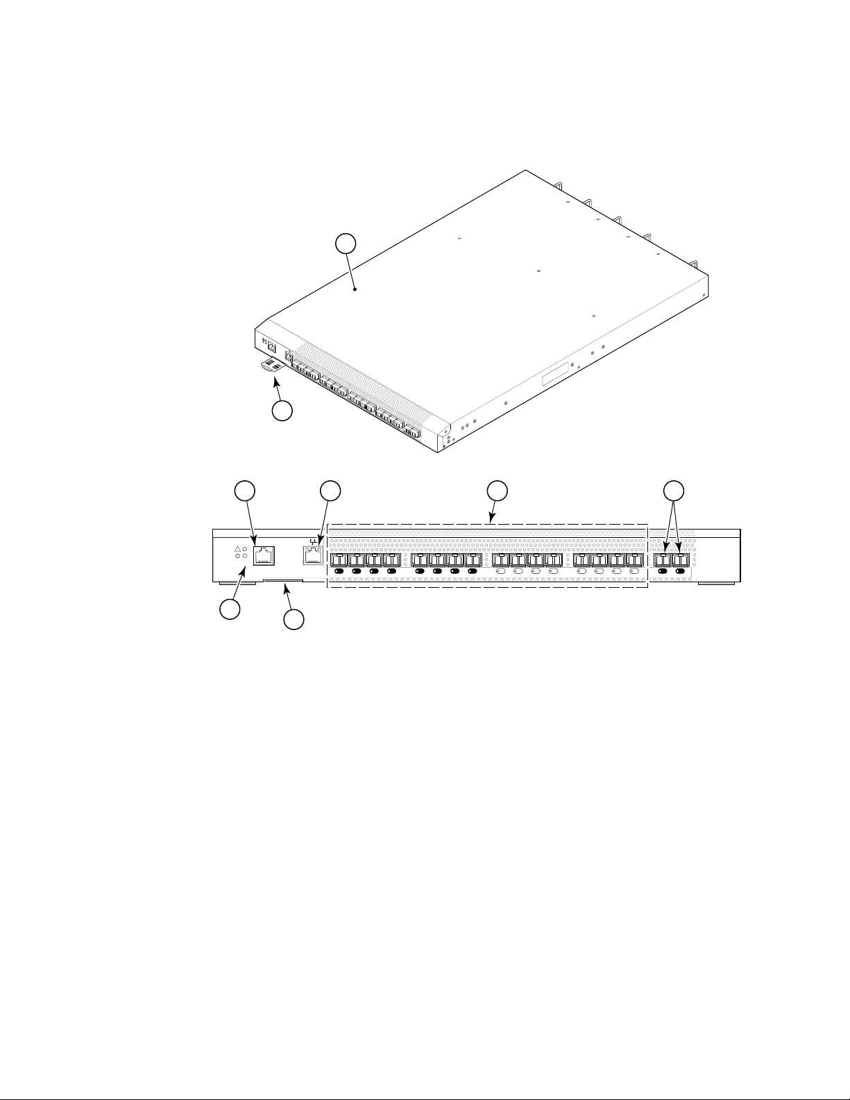
FIGURE 1 Port side view
1
!
!
I
O
I
O
I
Overview of Brocade 7500 series Extension Switches
scale: 1/8" = 1"
1
0
1
2
3
4
5
6
7
8
9
1
0
1
7
1
1
2
1
3
1
4
1
5
G
E
0
G
E
1
.
rack
n
r
i
o
f
64
h
/
t
3
ION:
1
r
eng
T
l
o
w
EN
mm
T
scre
be5
AT
o
t
mum
ng
i
Maxi
nt
mou
2 3 4 5
IOIOI
!
6
7
1 7500 or 7500E 5 GbE ports (2)
2 Console Management Port 6 System Status LED (top)
3 Ethernet Management Port System Power LED (bottom)
4 Fibre Channel Ports
7 IP Address pull out tab
• 16 for 7500 model
• 2 for 7500E model
GE1GE01514131211109876543210
The Fibre Channel ports are numbered from left to right on the faceplate (see Figure 2).
Brocade 7500 SAN Routers Hardware Reference Manual 5
53-1000026-03
Page 16
Overview of Brocade 7500 series Extension Switches
1
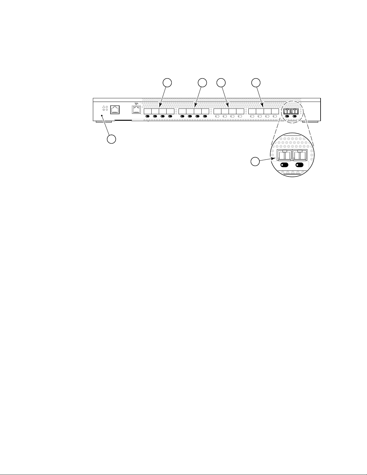
FIGURE 2 Port numbering in the 7500 Series Extension Switches
IOIOI
!
1
scale: 5/16" = 1"
5432
76543210
76543210
15141312111098
GE1GE015141312111098
6
GE1GE0
1 7500 or 7500E 4 Fibre Channel Ports 8 through 11
Ports not installed on base 7500E
model.
2 Fibre Channel Ports 0 through 3.
• For the base 7500E model,
only Fibre Channel Ports 0
5 Fibre Channel Ports 12 through 15
Ports not installed on base 7500E
model.
and 1 are installed.
• All ports are installed on the
7500 model.
3 Fibre Channel Ports 4 through 7
These ports not installed on base
7500E model.
The port side of the Brocade 7500 Extension Switches also displays the system status LED, power
status LED, and port status LEDs (Figure 4).
6 GbE ports (2)
6 Brocade 7500 SAN Routers Hardware Reference Manual
53-1000026-03
Page 17
Extension Switch management
1
Nonport side of the Extension Switch
Figure 3 shows the nonport side of the Brocade 7500 Series Extension Switches, which contain the
power supplies (including the AC power receptacle and AC power switch) and fans.
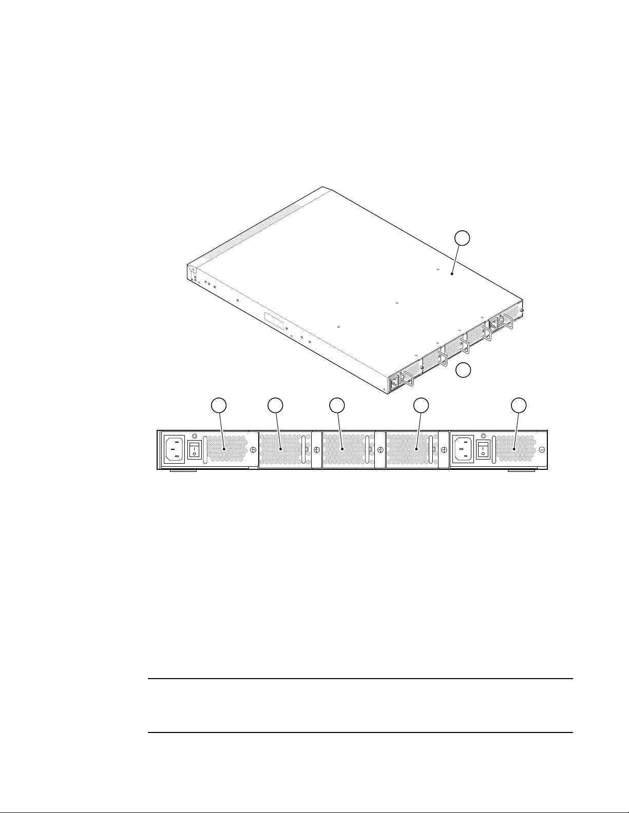
FIGURE 3 Nonport side of a 7500 Series Extension Switches.
1
scale: 1/8" = 1"
ATTEN
Ma
xi
TI
m
mo
ON:
umscr
u
n
t
i
n
gto
e
w
len
b
e5
g
th
mm
f
o
rra
o
r
1
c
3
k
/
6
4
i
n
.
43 5
1 7500 Extension Switches 5 Fan Assembly #2
2 Nonport Side of Extension
Switch
3 Power Supply #2 7 Power Supply #1
4Fan Assembly #3
Extension Switch management
You can use the management functions built into the Brocade 7500 Extension Switches to monitor
the fabric topology, port status, physical status, and other information to help you analyze
Extension Switch performance and to accelerate system debugging.
2
76
scale: 5/16" = 1"
6Fan Assembly #1
NOTE
The Brocade 7500 Extension Switches automatically perform a power-on self-test (POST) each time
it is turned on. Any errors are recorded in the error log. For more information about POST, see “POST
and boot specifications” on page 37.
Brocade 7500 SAN Routers Hardware Reference Manual 7
53-1000026-03
Page 18

Extension Switch management
1
For information about upgrading the version of Fabric OS installed on your Extension Switch, see
the Fabric OS Administrator’s Guide.
You can manage the Brocade 7500 Extension Switches using any of the management options
listed in Table 2.
TABLE 2 Management options for the Brocade 7500 Extension Switches
Management Tool Out-of-band Support In-band Support
Command line interface (CLI)
Up to two admin sessions and four user sessions simultaneously.
For more information, see the Fabric OS Administrator’s Guide and
the Fabric OS Command Reference.
Brocade Fabric Manager
For information, see the Fabric Manager User’s Guide.
Brocade Web Tools
For information, see the Web Tools Administrator’s Guide.
Standard SNMP applications
For information, see the Fabric OS MIB Reference.
Management Server
For information, see the Fabric OS Administrator’s Guide and the
Fabric OS Command Reference.
Ethernet or serial
management port
connection
Ethernet or serial
management port
connection
Ethernet or serial
management port
connection
Ethernet or serial
management port
connection
Ethernet or serial
management port
connection
IP over Fibre Channel
IP over Fibre Channel
IP over Fibre Channel
IP over Fibre Channel
Native in-band
interface
(over HBA only)
8 Brocade 7500 SAN Routers Hardware Reference Manual
53-1000026-03
Page 19

Chapter
Installing and configuring the Extension Switch
In this chapter
• “Installation and safety considerations,” next
• “Items included with the Extension Switch” on page 10
• “Setting up the Extension Switch as a standalone unit” on page 11
• “Installing in an EIA cabinet” on page 11
• “Initial setup of the Extension Switch” on page 11
• “Recommendations for cable management” on page 20
Installation and safety considerations
You can install the Extension Switch in the following ways:
• As a standalone unit on a flat surface. For instructions and more information, see “Setting up
the Extension Switch as a standalone unit” on page 11.
• In an EIA cabinet using the fixed rack mount kit, slide rack mount kit, or the mid-mount rack kit.
For more information, see “Installing in an EIA cabinet” on page 11.
To install and operate the SAN Router successfully, ensure that the following requirements are met:
2
• The primary AC input is 100-240 VAC (SAN Router autosenses input voltage), 47-63 Hz.
• The primary outlet is correctly wired, protected by a circuit breaker, and grounded in
accordance with local electrical codes.
• The supply circuit, line fusing, and wire size are adequate, as specified by the electrical rating
on the SAN Router nameplate.
For power supply information, see “Power supply specifications” on page 33.
To ensure adequate cooling, install the SAN Router with the nonport side, which contains the air
intake vents, facing a cool-air aisle.
Verify that the ambient air temperature does not exceed 400° C (104° F) and that the ambient
humidity remains between 20% and 85% while the SAN Router is operating.
If installing the SAN Router in a cabinet:
• The cabinet must be a standard EIA cabinet.
• Plan a cabinet space that is 1U (1.75 in.; 4.44 cm), 19 in. (48.3 cm) wide, and at least 24 in.
(61cm) deep.
• Ground all equipment in the cabinet through a reliable branch circuit connection and maintain
ground at all times. Do not rely on a secondary connection to a branch circuit, such as a power
strip.
Brocade 7500 Extension Switches Hardware Reference Manual 9
53-1000026-04
Page 20

Items included with the Extension Switch
2
• Ensure that airflow and temperature requirements are met on an ongoing basis, particularly if
the SAN Router is installed in a closed or multirack assembly.
• Verify that the additional weight of the SAN Router does not exceed the cabinet’s weight limits
or unbalance the cabinet in any way.
• Secure the cabinet to ensure stability in case of unexpected movement.
For additional installation, electrical, environmental, and other considerations, see the Brocade
Safety Guide.
Items included with the Extension Switch
The following items are included with the standard shipment of the Extension Switch:
• The 7500 Series Extension Switch, containing three fan assemblies and two power supplies
• The following rack mount kits are optionally available:
- Fixed rack mount kit, with installation instructions
- Slide rack mount kit, with installation instructions
- Mid-mount kit, with installation instructions
• One accessory kit, containing the following items:
- QuickStart Guide
- Brocade Documentation CD
- Brocade Fabric Manager Evaluation CD (not required for installation)
- Optional SFP transceivers for Fibre Channel ports.
• 16 for 7500 model.
• Two for 7500E model.
- 2 SFP transceivers for the GbE ports (optional)
- Rubber mounting feet (to be used when setting up the Extension Switch as a standalone
unit)
- Two grounded 6-ft (approximately 1.83 m) power cords:
• Power plug type is NEMA5-15
• Power plug current/voltage rating: 15A/125V
• Cordage type: SVT
• Current rating/wire gauge: 10A/ 18AWG
• Connector at system end of cordset: IEC 60320/ C13
- One RJ-45 serial cable, 10-ft (approximately 3 m) long. The Extension Switch uses an
RJ-45 connector for serial port. An RJ-45 to DB9 adaptor is also provided with the SAN
Router.
10 Brocade 7500 Extension Switches Hardware Reference Manual
53-1000026-04
Page 21

Setting up the Extension Switch as a standalone unit
Setting up the Extension Switch as a standalone unit
The Extension Switch can be configured as a standalone unit, which means that it resides outside
of a rack. Perform the following steps to configure the Extension Switch as a standalone unit.
1. Unpack the Extension Switch and verify that all ordered items are present.
2. Clean the four corner depressions on the bottom of the SAN Router and place a rubber foot in
each one. This helps prevent the SAN Router from accidentally sliding off the supporting
surface.
3. Place the SAN Router on a stable, flat surface.
Installing in an EIA cabinet
The Extension Switch can be installed in an EIA cabinet using one of the following optionally
available rack mount kits. Refer to the documentation that is shipped with the rack kit for
installation instructions.
• If you purchased the fixed rack mount kit, see the Fixed Rack Mount Kit Installation Procedure.
• If you purchased the mid-mount rack kit, see the Mid-Mount Rack Kit Installation Procedure.
• If you purchased the slide rack mount kit, see the Slide Rack Mount Kit Installation Procedure.
The Extension Switch can be installed using the slide rack mount kit in two ways:
- To allow the port side of the Extension Switch to slide out of the exhaust-air side of the
cabinet. In this installation, the port side of the Extension Switch is flush with the edge of
the cabinet.
- To allow the nonport side of the Extension Switch to slide out of the cool-air side of the
cabinet. In this installation, the port side of the Extension Switch is set 3 in. back from the
edge of the cabinet, allowing a more gradual bend in the fiber optic cables.
2
Initial setup of the Extension Switch
The Extension Switch must be configured correctly before it can operate within a network and
fabric. For instructions on configuring the Extension Switch to operate in a fabric containing
Extension Switches from other vendors, see the Fabric OS Administrator’s Guide.
The following items are required for configuring and connecting the Extension Switch for use in a
network and fabric:
• The Extension Switch, installed and connected to a power source
• A workstation computer that has a terminal emulator application (such as HyperTerminal for
Windows)
• An unused IP address and corresponding subnet mask and gateway address
• The serial cable provided with the Extension Switch
• An Ethernet cable
• SFP transceivers and compatible fiber cables, as required
• Access to an FTP server, for backing up (uploading) or downloading the Extension Switch
configuration
Brocade 7500 Extension Switches Hardware Reference Manual 11
53-1000026-04
Page 22

Initial setup of the Extension Switch
2
To configure the Extension Switch, you must perform the following tasks:
1. “Providing power to the Extension Switch” on page 12
2. “Creating a serial connection” on page 12
3. “Connecting to the Extension Switch Using the Serial Connection” on page 13
4. “Setting the Extension Switch IP Address” on page 13
5. “Creating an Ethernet connection” on page 14
6. “Setting the Extension Switch domain ID” on page 14
7. “Installing SFPs and cable the Extension Switch” on page 15
8. “Setting the Extension Switch date and time” on page 15
9. “Synchronizing local time with an external source” on page 16
10. “Correcting the time zone of a Extension Switch” on page 16
11. “FCIP and Fibre Channel routing services configuration” on page 17
12. “Verifying correct operation and backup the configuration” on page 18
CAUTION
Do not connect the Extension Switch to the network until the IP address is correctly set.
Providing power to the Extension Switch
Perform the following steps to provide power to the Extension Switch.
1. Connect the power cords to both power supplies and then to power sources on separate
circuits to protect against AC failure. Ensure that the cords have a minimum service loop of 6
in. available and are routed to avoid stress.
2. Power on the power supplies by flipping both AC switches to the “1” symbol. The power supply
LEDs display amber until POST is complete, and then change to green. The Extension Switch
usually requires from 1 to 3 minutes to boot and complete POST.
NOTE
Power is supplied to the Extension Switch as soon as the first power supply is connected and turned
on.
3. After POST is complete, verify that the Extension Switch power and status LEDs on the left of
the port side of the Extension Switch are green.
Creating a serial connection
Perform the following steps to create a serial connection to the Extension Switch.
12 Brocade 7500 Extension Switches Hardware Reference Manual
53-1000026-04
Page 23

Initial setup of the Extension Switch
1. Remove the plug from the serial port and insert the serial cable provided with the Extension
Switch.
2. Connect the serial cable to the serial port on the Extension Switch and to an RS-232 serial port
on the workstation. If the serial port on the workstation is RJ-45 instead of RS-232, you can
remove the adapter on the end of the serial cable and insert the exposed RJ-45 connector into
the RJ-45 serial port on the workstation.
3. Disable any serial communication programs running on the workstation.
4. Open a terminal emulator application (such as HyperTerminal for Windows or TERM in a UNIX
environment) and configure the application as follows:
2
• In a Windows NT, 2000, 2003, ME, or XP environment:
Bits per second: 9600
Databits: 8
Parity: None
Stop bits: 1
Flow control: None
• In a UNIX environment, enter the following command at the prompt:
tip /dev/ttyb -9600
Connecting to the Extension Switch Using the Serial Connection
Perform the following steps to log in to the Extension Switch through the serial connection.
1. Verify that the Extension Switch has completed POST. When POST is complete, the port status
and Extension Switch power and status LEDs return to a standard healthy state; for information
about LED signals, see “Powering off the Extension Switch” on page 29.
2. When the terminal emulator application stops reporting information, press Enter to display the
login prompt.
3. Log in to the Extension Switch as admin, using the default password: password. You are
prompted to change the default passwords at initial login.
Setting the Extension Switch IP Address
Perform the following steps to replace the default IP address and related information.
1. Enter the ipAddrSet command at the terminal emulator application prompt, and enter the
requested information at the prompts:
switch:admin> ipaddrset
Ethernet IP Address [10.77.77.77]:10.32.53.47
Ethernet Subnetmask [255.0.0.0]:255.255.240.0
Fibre Channel IP Address [0.0.0.0]: 20.32.233.48
Fibre Channel Subnetmask [0.0.0.0]: 255.255.230.0
Gateway IP Address [0.0.0.0]:10.32.48.1
IP address is being changed...Done.
Committing configuration...Done.
switch:admin>
Brocade 7500 Extension Switches Hardware Reference Manual 13
53-1000026-04
Page 24

Initial setup of the Extension Switch
2
2. Optionally, verify that the address was correctly set by entering the ipAddrShow command at
the prompt.
3. Record the IP address on the pull out tab (see Figure 1 on page 5) provided for this purpose on
the port side of the Extension Switch.
4. If the serial port is no longer required, log out of the serial console, remove the serial cable,
and replace the plug in the serial port.
Creating an Ethernet connection
Perform the following steps to create an Ethernet connection to the Extension Switch.
1. Remove the plug from the Ethernet port.
2. Connect an Ethernet cable to the Extension Switch Ethernet port and to the workstation or to
an Ethernet network containing the workstation.
NOTE
At this point, the Extension Switch can be accessed remotely, by command line or by Web Tools.
Ensure that the Extension Switch is not being modified from any other connections during the
remaining tasks.
Setting the Extension Switch domain ID
Perform the following steps to set the Extension Switch domain ID.
1. Log on to the Extension Switch through Telnet, using the admin account.
2. Modify the domain ID if required.
The default domain ID is 1. If the Extension Switch is not powered on until after it is connected
to the fabric and the default domain ID is already in use, the domain ID for the new Extension
Switch is automatically reset to a unique value. If the Extension Switch is connected to the
fabric after it has been powered on and the default domain ID is already in use, the fabric
segments. To find the domain IDs that are currently in use, run the fabricShow command on
another Extension Switch in the fabric.
a. Disable the Extension Switch by entering the switchDisable command.
b. Enter the configure command. The command prompts display sequentially; enter a new
value or press Enter to accept each default value.
c. Enter y after the “Fabric param” prompt:
Fabric param (yes, y, no, n): [no] y
d. Enter a unique domain ID (such as the domain ID used by the previous Extension Switch, if
still available):
Domain: (1..239) [1] 3
e. Complete the remaining prompts or press Ctrl-D to accept the remaining settings without
completing all the prompts.
f. Re-enable the Extension Switch by entering the switchEnable command.
14 Brocade 7500 Extension Switches Hardware Reference Manual
53-1000026-04
Page 25

Initial setup of the Extension Switch
2
Installing SFPs and cable the Extension Switch
Perform the following steps to install SFPs and cable the Extension Switch.
1. Install the SFP transceivers in the Fibre Channel ports, as required. The ports selected for use
in trunking groups must meet specific requirements. For a list of these requirements, see the
Fabric OS Administrator’s Guide.
a. Remove the plugs from the ports to be used.
b. Position a transceiver so that it is oriented correctly and insert it into a port until it is firmly
seated and the latching mechanism clicks.
For instructions specific to the type of transceiver, see the transceiver manufacturer’s
documentation.
NOTE
The transceivers are keyed to ensure correct orientation. If a transceiver does not install
easily, ensure that it is correctly oriented.
c. Repeat Steps a and b for the remaining ports, as required.
2. Connect the cables to the transceivers.
The cables used in trunking groups must meet specific requirements. For a list of these
requirements, see the Fabric OS Administrator’s Guide.
CAUTION
A 50-micron cable should not be bent to a radius less than 2 in. under full tensile load and 1.2 in.
with no tensile load. Tie wraps are not recommended for optical cables because they are easily
overtightened.
a. Orient a cable connector so that the key (the ridge on one side of connector) aligns with
the slot in the transceiver. Then, insert the cable into the transceiver until the latching
mechanism clicks. For instructions specific to cable type, see the cable manufacturer’s
documentation.
NOTE
The cable connectors are keyed to ensure correct orientation. If a cable does not install
easily, ensure that it is correctly oriented.
b. Repeat Step a for the remaining cables as required.
3. Check the LEDs to verify that all components are functional. For information about LED
patterns, see “Powering off the Extension Switch” on page 29.
4. Verify the correct operation of the Extension Switch by entering the switchShow command from
the workstation.
Setting the Extension Switch date and time
The date and time Extension Switch settings are used for logging events. Extension Switch
operation does not depend on the date and time; a Extension Switch with incorrect date or time
values still functions properly.
Brocade 7500 Extension Switches Hardware Reference Manual 15
53-1000026-04
Page 26

Initial setup of the Extension Switch
2
You can synchronize the local time of the principal or primary fabric configuration server (FCS)
Extension Switch to that of an external Network Time Protocol (NTP) server.
Perform the following steps to set the date and time of a Extension Switch.
1. Log in to the Extension Switch as admin.
2. Enter the date command at the command line using the following syntax:
date “MMDDhhmm[CC]YY”
where:
• MM is the month (01-12)
• DD is the date (01-31)
• hh is the hour (00-23)
• mm is minutes (00-59)
• CC is the century (19-20)
• YY is the year (00-99)
Year values greater than 69 are interpreted as 1970-1999; year values less than 70 are
interpreted as 2000-2069. The date function does not support Daylight Savings Time or time
zones, so changes will have to be reset manually.
switch:admin> date
Fri May 5 21:50:00 UTC 1989
switch:admin>
switch:admin> date "0624165203"
Tue Jun 24 16:52:30 UTC 2003
switch:admin>
Synchronizing local time with an external source
Perform the following steps to synchronize the local time of the principal or primary FCS switch with
that of an external NTP server.
1. Log in as admin.
2. Enter the tsClockServer ipaddr command.
The ipaddr variable represents the IP address of the NTP server that the Extension Switch can
access. This argument is optional; by default the value is “LOCL”.
switch:admin> tsclockserver
LOCL
switch:admin> tsclockserver 132.163.135.131
switch:admin>
Correcting the time zone of a Extension Switch
If the time of your Extension Switch is off by hours (and not minutes), use the following procedure
on all Extension Switches.
Perform the following steps to set the time zone.
1. Log in as admin.
2. Enter the tsTimeZone command as follows:
16 Brocade 7500 Extension Switches Hardware Reference Manual
53-1000026-04
Page 27

Initial setup of the Extension Switch
tstimezone [houroffset [, minuteoffset]]
For Pacific Standard Time, enter tsTimeZone -8,0
For Central Standard Time, enter tsTimeZone -6,0
For Eastern Standard Time, enter tsTimeZone -5,0
The default time zone for Extension Switches is universal time conversion (UTC), which is 8
hours ahead of Pacific Standard Time. Additional time zone conversions are listed later in this
section.
The parameters listed do not apply if the time zone of the Extension Switches has already been
changed from the default (8 hours ahead of PT).
For more detailed information about the command parameters, see the tsTimeZone command
in the Fabric OS Command Reference.
3. Repeat steps 1 and 2 on all Extension Switches that the time zone needs to be set.
This needs to be done only once, because the value is stored in nonvolatile memory. For U.S.
time zones, use Table 3 to determine the correct parameter for the tsTimeZone command.
TABLE 3 tsTimeZone command parameter selection
2
Local Time tsTimeZone parameter (difference from UTC)
Atlantic Standard -4,0
Atlantic Daylight -3,0
Eastern Standard -5,0
Eastern Daylight -4,0
Central Standard -6,0
Central Daylight -5,0
Mountain Standard -7,0
Mountain Daylight -6,0
Pacific Standard -8,0
Pacific Daylight -7,0
Alaskan Standard -9,0
Alaskan Daylight -8,0
Hawaiian Standard -10,0
FCIP and Fibre Channel routing services configuration
The ports on the Extension Switch are initially set to persistently disabled.
If you want to enable the FC ports as a standard E_Port or F_port use the portcfgpersistentenable
command to enable the ports.
If you are using the FC ports as EX_Ports you must configure the Fibre Channel Routing Services
feature prior to enabling the ports.
The GbE ports can only be used once you have configured FCIP and enabled the VE_Ports.
Brocade 7500 Extension Switches Hardware Reference Manual 17
53-1000026-04
Page 28

Initial setup of the Extension Switch
2
See the Fabric OS Administrator’s Guide for detailed instructions on configuring the Fibre Channel
Router ports and GbE ports on the Extension Switch.
Verifying correct operation and backup the configuration
Perform the following steps to verify correct operation and backup with Extension Switch
configuration.
1. Check the LEDs to verify that all components are functional. For information about LED
patterns, see “Powering off the Extension Switch” on page 29.
2. Run the portcfgpersistentenable command to activate the FC ports for FC operation.
3. Verify the correct operation of the Extension Switch by entering the switchShow command from
the workstation.
This command provides information about Extension Switch and port status. The switfchShow
output is from a 7500 model.
18 Brocade 7500 Extension Switches Hardware Reference Manual
53-1000026-04
Page 29

Initial setup of the Extension Switch
sw7500:admin> switchshow
switchName: sw7500
switchType: 46.2
switchState: Online
switchMode: Native
switchRole: Subordinate
switchDomain: 49
switchId: fffc31
switchWwn: 10:00:00:05:1e:37:0d:a5
zoning: ON (cfg_em)
switchBeacon: OFF
FC Router BB Fabric ID: 1
Area Port Media Speed State
==============================
0 0 id N4 Online E-Port 10:00:00:60:69:e4:20:3e "sw48000"
(upstre
am)(Trunk master)
1 1 id N4 No_Light
2 2 id 2G Online LS E-Port (Trunk port, master is Port 3 )
3 3 id 2G Online LS E-Port 10:00:00:60:69:e4:20:3e "sw48000"
(Tru
nk master)
4 4 id N4 No_Light
5 5 id N4 No_Light
6 6 id N4 No_Light
7 7 id N4 No_Light
8 8 id N2 No_Light
9 9 id N2 No_Light
10 10 id N2 No_Light
11 11 id N2 No_Light
12 12 id N4 No_Light
13 13 id N4 No_Light
14 14 id N4 No_Light
15 15 id N4 No_Light
16 16 -- -- Online VE-Port 10:00:00:60:69:e4:20:3e "sw48000"
17 17 -- -- Online VE-Port 10:00:00:60:69:e4:20:3e "sw48000"
18 18 -- -- Online VE-Port 10:00:00:60:69:e4:20:3e "sw48000"
19 19 -- -- Online VE-Port 10:00:00:60:69:e4:20:3e "sw48000"
20 20 -- -- Online VE-Port 10:00:00:60:69:e4:20:3e "sw48000"
21 21 -- -- Online VE-Port 10:00:00:60:69:e4:20:3e "sw48000"
22 22 -- -- Online VE-Port 10:00:00:60:69:e4:20:3e "sw48000"
2
<continued on next page>
Brocade 7500 Extension Switches Hardware Reference Manual 19
53-1000026-04
Page 30

Recommendations for cable management
2
23 23 -- -- Online VE-Port 10:00:00:60:69:e4:20:3e "sw48000"
24 24 -- -- Online VE-Port 10:00:00:60:69:e4:20:3e "sw48000"
25 25 -- -- Online VE-Port 10:00:00:60:69:e4:20:3e "sw48000"
26 26 -- -- Online VE-Port 10:00:00:60:69:e4:20:3e "sw48000"
27 27 -- -- Online VE-Port 10:00:00:60:69:e4:20:3e "sw48000"
28 28 -- -- Online VE-Port 10:00:00:60:69:e4:20:3e "sw48000"
29 29 -- -- Online VE-Port 10:00:00:60:69:e4:20:3e "sw48000"
30 30 -- -- Online VE-Port 10:00:00:60:69:e4:20:3e "sw48000"
31 31 -- -- Online VE-Port 10:00:00:60:69:e4:20:3e "sw48000"
ge0 id 1G Online
ge1 id 1G Online
sw7500:admin:
NOTE
For a base 7500E Extension Switch, switchName displays as sw7500E. Ports 0 and 1 are
installed and will display current SwitchState, such as offline, online, testing, or faulty. Ports
2-15 display “No Module.” The SwitchState for ports 17-23 (virtual ports on ge0) and ports
25-31 (virtual port on ge1) displays as “Offline.”
4. Verify the correct operation of the Extension Switch in the fabric by entering the fabricShow
command from the workstation.
This command provides general information about the fabric.
5. Back up the Extension Switch configuration to an FTP server by entering the configUpload
command and following the prompts.
This command uploads the Extension Switch configuration to the server, making it available for
downloading to a replacement Extension Switch if necessary.
Brocade recommends backing up the configuration on a regular basis to ensure that a
complete configuration is available for downloading to a replacement Extension Switch. For
specific instructions about how to back up the configuration, see the Fabric OS Administrator’s
Guide. The switchShow, fabricShow, and configUpload commands are described in detail in
the Fabric OS Command Reference.
Recommendations for cable management
Cables can be organized and managed in a variety of ways, such as by using cable channels or
patch panels. Note the following recommendations:
• Plan cable management before installing the Extension Switch in a rack.
• Leave at least one meter (three feet) of slack for each port cable. This provides room to remove
and replace the Extension Switch, allows for inadvertent movement of the rack, and helps
prevent the cables from being bent to less than the minimum bend radius.
CAUTION
A 50-micron cable should not be bent to a radius less than 2 in. under full tensile load and 1.2 in.
with no tensile load. Tie wraps are not recommended for optical cables because they are easily
overtightened.
20 Brocade 7500 Extension Switches Hardware Reference Manual
53-1000026-04
Page 31

Chapter
Operating the Extension Switch
In this chapter
• “LED activity,” next
• “Interpreting POST results” on page 27
• “Extension Switch maintenance” on page 27
• “Powering off the Extension Switch” on page 29
LED activity
System activity and status can be determined through the activity of the LEDs on the Extension
Switch.
There are three possible LED states:
• No light
• Steady light
• Flashing light
The lights are in one of the following colors:
3
• Green
• Amber
The status LEDs may display amber or flash during boot, POST, or other diagnostic tests. This is
normal; it does not indicate a problem unless the LEDs do not indicate a healthy state after all boot
processes and diagnostic tests are complete.
Brocade 7500 Extension Switches Hardware Reference Manual 21
53-1000026-04
Page 32

3
LED activity
LEDs on the port side of the Extension Switch
The port side of the Extension Switch has the following LEDs:
• One system status LED (above) on the left side
• One power status LED (below) on the left side
• Ethernet speed and status LEDs
• One port status LED for each Fibre Channel port on the Extension Switch. The port LEDs are
located in the array in the same relative positions as the ports.
• One port status LED for each GbE port
Figure 4 on page 23 shows the port side of the Brocade 7500 Series Extension Switches.
22 Brocade 7500 Extension Switches Hardware Reference Manual
53-1000026-04
Page 33

LED activity
NOTE
The base 7500E model is shipped with Fibre Channel ports 0 and 1, plus the two GbE ports
installed. The 7500 model is shipped can have all 16 Fibre Channel ports installed.
FIGURE 4 LEDs on port side
IOIOI
!
3210
3
8
2 3 4
6 7
5
IOIOI
!
1
scale: 5/16" = 1"
GE1GE0
12
1 7500 or 7500E 7 Ethernet Link LED
10
9
GE1GE01514131211109876543210
11
scale: 3/4" = 1"
2 System Status LED 8 Ethernet Port
3 System Power LED 9 Fibre Channel Ports 0-3
4 Console Port 10 Port 0 Status LED
5 IP Address Pull Out Tab 11 GbE ports (2)
6 Ethernet Speed LED 12 GE0 port
Brocade 7500 Extension Switches Hardware Reference Manual 23
53-1000026-04
Page 34

3
LED activity
Tab le 4 describes the LEDs and their actions on the port side of the Extension Switch.
TABLE 4 Port Side LED patterns during normal operation
LED Name LED Color Status of Hardware Recommended Action
Power Status No light System is off or there is an internal
power supply failure.
Steady green System is on and power supplies are
functioning properly.
System Status No light System is off or there is no power. Verify that system is on and has
Steady green System is on and functioning
properly.
Steady amber (for
more than five
seconds)
Flashing
amber/green
Ethernet
Speed
Ethernet Link No light There is no link. Verify that the Ethernet cable is
No light Port speed is 10 Mbps No action required.
Steady green Port speed is 100 Mbps No action required.
Steady green There is a link. No action required.
Flashing green There is link activity (traffic). No action required.
Unknown state, boot failed, or the
system is faulty.
This LED displays steady amber
during POST; this is normal and does
not indicate a fault.
Attention is required. A number of
variables can cause this status
including a single power supply
failure, a fan failure, or one or more
environmental ranges has exceeded.
Verify that system is powered on
(power supply switches to “1”), the
power cables attached, and your
power source is live.
If the system power LED is not green,
the unit may be faulty.
Contact your Extension Switch
service provider.
No action required.
completed booting.
No action required.
Perform the following steps:
1 Connect a serial cable to the
system.
2 Reboot the system.
3 Check the failure indicated on
the system console
4 Contact your Extension Switch
service provider.
Check the management interface
and the error log for details on the
cause of status.
Contact your Extension Switch
service provider.
connected correctly.
24 Brocade 7500 Extension Switches Hardware Reference Manual
53-1000026-04
Page 35

LED activity
TABLE 4 Port Side LED patterns during normal operation (Continued)
LED Name LED Color Status of Hardware Recommended Action
3
Port Status No light Indicates one of the following:
• No signal or light carrier (media
or cable) detected.
• Blade may be currently
initializing.
• Connected device is configured
in an offline state.
Steady green Port is online (connected to external
device) but has no traffic.
Slow-flashing
green (on 1
second; then off 1
second)
Fast-flashing green
(on 1/4 second;
then off 1/4
second)
Flickering green Port is online and frames are flowing
Steady amber Port is receiving light or signal
Slow-flashing
amber (on 2
seconds; then off
2 seconds)
Fast-flashing
amber (on 1/2
second; then off
1/2 second)
Port is online but segmented
because of a lookback cable or
incompatible Extension Switch
connection.
Port is online and an internal
loopback diagnostic test is running.
through the port.
carrier, but it is not online yet.
Port is disabled because of
diagnostics or the portDisable
command.
SFP or port is faulty. Replace the SFP.
• Verify the power LED is on, and
check the SFP and cable.
• Verify the blade is not currently
being initialized.
• Verify the status of the
connected device.
No action required.
Verify that the correct device is
attached to the blade.
No action required.
No action required.
No action required.
Reset the port.
The portCfgPersistentDisable
command is persistent across
reboots in Fabric OS v5.0.1.
Reset the port.
Brocade 7500 Extension Switches Hardware Reference Manual 25
53-1000026-04
Page 36

3
LED activity
LEDs on the nonport side of the Extension Switch
The nonport side of the Extension Switch has the following LEDs:
• One power supply LED above the AC power switch on each power supply.
• One fan status LED near the handle of each fan assembly.
Tab le 5 describes the LEDs on the nonport side of the Extension Switch.
TABLE 5 Nonport side LED patterns during normal operation
LED Name LED Color Status of Hardware Recommended Action
Power Supply
Status
No light Power supply is not seated
correctly.
Steady green Power supply is operating
normally.
Steady amber (for more than
five seconds)
Power supply fault for one of
the following reasons:
• Power supply is
switched off.
• The power cable is
disconnected.
• The power supply has
failed.
Note: When the Extension
Switch is first powered on
the power supply status LED
will show amber until POST
has completed.
Fan Status No light Fan assembly is not
receiving power.
Steady green Fan assembly is operating
normally.
Steady amber (for more than
five seconds)
Fan fault for one of the
following reasons:
• One or more of the
fan(s) in the fan
assembly has failed.
• The fan FRU was
disabled by the user.
Note: When the Extension
Switch is first powered on
the fan status LED will show
amber until POST has
completed.
Verify that the power supply
is seated correctly.
No action required.
Try th e follo wing:
• Check the power cable
connection.
• Verify that the power
supply is powered on.
• Replace the power
supply FRU.
No action required.
No action required.
Try th e follo wing:
• Verify that the fan FRU
is enabled (use the
fanEnable command).
• Replace the fan FRU.
26 Brocade 7500 Extension Switches Hardware Reference Manual
53-1000026-04
Page 37

Interpreting POST results
POST is a system check that is performed each time the Extension Switch is powered on, rebooted,
or reset, and during which the LEDs flash different colors.
Perform the following steps to determine whether POST completed successfully and whether any
errors were detected.
1. Verify that the LEDs on the Extension Switch indicate that all components are healthy (LED
patterns are described in Table 4 on page 24 and Table 5 on page 26). If one or more LEDs do
not display a healthy state:
a. Verify that the LEDs are not set to “beacon” (this can be determined through the
switchShow command or Web Tools). For information about how to turn beaconing on and
off, see the Fabric OS Administrator’s Guide or the Advanced Web Tools Administrator’s
Guide.
b. Follow the recommended action for the observed LED behavior, as listed in
Tab le 4 or Tab le 5.
2. Verify that diagShow command displays that the diagnostic status for all ports in the Extension
Switch is OK.
Interpreting POST results
3
3. Review the system log for errors. Errors detected during POST are written to the system log,
which is viewed using the errShow command. For more information about this command, see
the Fabric OS Command Reference. For information about specific error messages, see the
Fabric OS Message Reference.
Extension Switch maintenance
The Brocade 7500 Extension Switches are designed for high availability and low failure; it does not
require any regular physical maintenance. It includes diagnostic tests and field-replaceable units,
described in the following sections.
Diagnostic tests
In addition to POST, Fabric OS includes diagnostic tests to help you troubleshoot the hardware and
firmware. This includes tests of internal connections and circuitry, fixed media, and the
transceivers and cables in use. The tests are implemented by command, either through a Telnet
session or through a terminal set up for a serial connection to the Extension Switch. Some tests
require the ports to be connected by external cables, to allow diagnostics to verify the
serializer/deserializer interface, transceiver, and cable. Some tests require loop back plugs.
Diagnostic tests are run at link speeds of 1-Gbps, 2-Gbps, and 4-Gbps. For information about
specific diagnostic tests, see the Fabric OS Administrator’s Guide.
NOTE
Diagnostic tests might temporarily lock the transmit and receive speed of the links during diagnostic
testing.
Brocade 7500 Extension Switches Hardware Reference Manual 27
53-1000026-04
Page 38

Extension Switch maintenance
3
Field replaceable units (FRUs)
You can replace the power supplies and fan assemblies onsite without the use of special tools. The
power supplies and fan assemblies are keyed to ensure correct orientation during installation.
Replacement instructions are provided with all replacement units ordered.
ATTENTION
The Brocade 7500 Extension Switches have two power cords. To remove all power from a Extension
Switch, disconnect both power cords before servicing.
Power Supplies
The two power supplies are hot-swappable. They are identical and fit into either power supply slot.
Fabric OS identifies the power supplies as follows (viewing the Extension Switch from the nonport
side):
• Power supply #1 on the right
• Power supply #2 on the left
Any of the following methods can be used to determine whether a power supply requires replacing:
• Check the power supply status LED next to the On/Off switch (see “LEDs on the nonport side of
• Enter the psShow command at the command prompt to display power supply status as shown
the Extension Switch” on page 26)
below: Following is output for the 7500 model.
sw7500:admin> psshow
Power Supply #1 is OK
V10529, TQ2H0000118 ,60-0300031-01,X2, ,SP640
,2X,TQ2H0000
Power Supply #2 is OK
V10529, TQ2H0000121 ,60-0300031-01,X2, ,SP640
,2X,TQ2H0000
sw7500:admin>
• In Web Tools, click the Power Status icon.
Fan assemblies
The three fan assemblies are hot-swappable. They are identical and fit into any fan assembly slot.
Each fan assembly contains two fans, identified by Fabric OS as follows (viewing the Extension
Switch from the nonport side):
• Fan assembly #1 on the right
• Fan assembly #2 in the center
• Fan assembly #3 on the left
Any of the following methods can be used to determine whether a fan assembly requires replacing:
• Check the fan status LED on the face of the fan assembly (see “LEDs on the nonport side of
the Extension Switch” on page 26)
28 Brocade 7500 Extension Switches Hardware Reference Manual
53-1000026-04
Page 39

• Enter the fanShow command at the command prompt.Following is output for the 7500 model.
sw7500:admin> fanshow
Fan 1 is Ok, speed is 9507 RPM
Fan 2 is Ok, speed is 9246 RPM
Fan 3 is Ok, speed is 9246 RPM
sw7500:admin>
• In Web Tools, click the Fan Status icon.
Powering off the Extension Switch
Perform the following steps to power off the Extension Switch.
1. Run the sysShutdown command.
2. Set each AC power switch to “0”.
Powering off the Extension Switch
3
Brocade 7500 Extension Switches Hardware Reference Manual 29
53-1000026-04
Page 40

Powering off the Extension Switch
3
30 Brocade 7500 Extension Switches Hardware Reference Manual
53-1000026-04
Page 41

Appendix
Product specifications
This appendix provides the following information:
• “Extension switch components,” next
• “Weight and physical dimensions” on page 32
• “Facility requirements” on page 32
• “Power supply specifications” on page 33
• “Power cords (Japan, Denan)” on page 33
• “Power cords (Japan, Denan)” on page 33
• “General specifications” on page 35
• “Data transmission ranges” on page 36
• “Memory specifications” on page 36
• “Fibre Channel port specifications” on page 36
• “GbE port specifications” on page 36
• “Serial port specifications” on page 37
• “POST and boot specifications” on page 37
• “Federal information processing standards (FIPS)” on page 38
• “Regulatory compliance” on page 38
A
Extension switch components
The Extension Switch includes the following components:
• Cabinet-mountable 1U chassis designed to be mounted in a 19-in. cabinet space, with
forced-air cooling that flows from the nonport side of the Extension Switch to the port side.
• 16 Fibre Channel ports, compatible with short wavelength (SWL), long wavelength (LWL), and
extended long wavelength (ELWL) SFP transceivers.
• 2 GbE ports (1-Gbps), compatible with short wavelength (SWL), long wavelength (LWL), and
extended long wavelength (ELWL) SFP transceivers.
• One IEEE-compliant RJ-45 serial cable, 10-ft (approximately 3 m) long. An RJ-45 to DB9
adaptor is also provided with the Extension Switch.
• One IEEE-compliant RJ-45 connector on the port side of the Extension Switch for use with a
serial console and 10/100 MBps Ethernet.
• Extension Switch status and management LEDs: 1 Extension Switch power LED, 1 Extension
Switch status LED, 2 Ethernet LEDs, 2 power supply LEDs, and 3 fan LEDs.
• Port status LEDs: 16 Fibre Channel port status LEDs, and 2 GbE port status LEDs.
• 2 universal AC input and redundant power supplies with AC switches and built-in fans.
Brocade 7500 Extension Switches Hardware Reference Manual 31
53-1000026-04
Page 42

Weight and physical dimensions
A
• 3 fan assemblies containing two fans each. The fans have two speeds, which are set
automatically and cannot be modified. They default to high speed upon boot, then switch to
low speed as Fabric OS comes online, returning to high speed only as required.
Weight and physical dimensions
Tab le 6 lists the weight and dimensions of the Extension Switch.
TABLE 6 Physical specifications
Dimension Value
Height 1U = 42.44 mm (1.67 in.)
Depth 635mm (25.0 in.)
Width 429 mm (16.89 in.)
Weight (with two power supplies and three fan
assemblies installed)
12.43 kg (27.4 lbs)
Facility requirements
To ensure correct operation of the Extension Switch, the facility where the Extension Switch is in
use must meet the following requirements:
• Electrical:
- Primary AC input 100-240 VAC (Extension Switch autosenses input voltage), 47-63 Hz.
- Correctly wired primary outlet, protected by a circuit breaker and grounded in accordance
with local electrical codes.
- Adequate supply circuit, line fusing, and wire size, as specified by the electrical rating on
the Extension Switch nameplate.
- Electrical interference must be less than the levels stated in the standards listed in Tab le 9
on page 35, under “Immunity.”
• Thermal:
- A minimum air flow of 56.5 cu ft/min (96 cu m/hr) available in the immediate vicinity of
the Extension Switch. (Air flows from the nonport side to the port side.)
- Ambient air temperature must not exceed 40° C (104° F) while the Extension Switch is
operating.
• Environmental: Specifications are listed in Table 8 on page 34.
• Cabinet:
- Cabinet space of one rack unit in a 19-in. cabinet.
- All equipment in cabinet must be grounded through a reliable branch circuit connection.
- The additional weight of the Extension Switch must not exceed the cabinet’s weight limits.
- The cabinet must be secured to ensure stability in case of unexpected movement.
32 Brocade 7500 Extension Switches Hardware Reference Manual
53-1000026-04
Page 43

Power supply specifications
The power supplies are universal and capable of functioning worldwide without voltage jumpers or
switches. They meet IEC 61000-4-5 surge voltage requirements and are autoranging in terms of
accommodating input voltages and line frequencies. Each power supply has a built-in fan for
cooling, pushing air towards the port side of the Extension Switch.
Tab le 7 lists the power supply specifications for the Extension Switch.
TABLE 7 Power supply specifications
Specification Value
Outlet The outlet must be a correctly wired, primary with earth ground
Maximum output 300 Watts
System power consumption 240W Max, 215W typical
Input voltage 85-264 VAC, Universal
Input line frequency 47 - 63 Hz
Harmonic distortion Active power factor correction
BTU rating at 80% efficiency 240W X 3.412 BTU/hr/Watts = 820 BTU/Hr
Inrush current Maximum of 15 amps for period between 10-150 ms at 50 degrees C
Input line protection Fused in both hot and neutral lines, using independent fuses
Power supply specifications
(122 degrees F), hot or cold start
A
Power cords (Japan, Denan)
ATTENTION
Never use the power cord packed with your equipment for other products.
Brocade 7500 Extension Switches Hardware Reference Manual 33
53-1000026-04
Page 44

Environmental requirements
A
Environmental requirements
Tab le 8 lists the acceptable environmental ranges for both operating and nonoperating (such as
during transportation or storage) conditions.
TABLE 8 Environmental requirements
Condition Acceptable During Operation Acceptable During Non-Operation
Ambient
Tem pera ture
Humidity 20% to 85% RH non-condensing, at
Altitude 0 to 3 km (10,000 ft) above sea level 0 to 12 km (40,000 ft) above sea level
Shock 20 G, 6 ms, half-sine wave 15 G, 12-18 ms, trapezoid
Vibration 0.5 G, 5-500 Hz 2.0 G, 5-500 Hz
Air Flow 31 cu ft/min (52.7 cu m/hr) NA
0° to 40° C
(32
° to 104° F)
40° C (104
per hour
° F), with maximum gradient of 10%
° to 70° C
-25
(-13
° to 158° F)
10% to 85% RH non-condensing, at 70° C
(158
° F)
34 Brocade 7500 Extension Switches Hardware Reference Manual
53-1000026-04
Page 45

General specifications
Tab le 9 lists the general specifications for the Extension Switch.
TABLE 9 General specifications
Specification Description
Configurable port types The GbE ports can be VE_Ports or VEX_Ports.
EMC (electromagnetic compatibility) Emissions
System architecture Nonblocking shared-memory Extension Switch
System processor PowerPC 440GX, 800 MHz CPU
ANSI Fibre Channel protocol FC-PH (Fibre Channel Physical and Signalling Interface standard)
Modes of operation Fibre Channel Class 2 and Class 3
Fabric initialization Complies with FC-SW-3 Rev. 6.6
FC-IP (IP over Fibre Channel) Complies with FC-IP 2.3 of FCA profile
Aggregate Extension Switch I/O
bandwidth
Port-to-port latency Less than 2 microseconds with no contention (destination port is free)
General specifications
The Fibre Channel ports can be E_Ports, EX_Ports, FL_Ports, or F_Ports.
An operating Extension Switch conforms to the emissions
requirements specified by the following regulations:
A
• FCC Rules & Regulations, Part 15 subpart B, Class A
• CSA C108.8 Class A
• VCCI Class A ITE
• CISPR 22 Class A
• EN55022 Class A
• Korean EMC Requirements
• BSMI Standard CNS 13438
• EMC Directive 89/336/EEC
• EN50082-2/EN55024: 1998
• ICES-003 Class A
Immunity
• IEC 61000-4-2 Severity Level 3 for Electrostatic Discharge
• IEC 61000-4-3 Severity Level 3 for Radiated Fields
• IEC 61000-4-4 Severity Level 3 for Fast Transients
• IEC 61000-4-5 Severity Level 3 for Surge Voltage
• IEC 61000-4-6 Conducted Emissions
• IEC 61000-4-11 Voltage Variations
• EN 61000-4-12 Oscillatory Waves Immunity
• EN 61000-3-2 Limits for Harmonic Current Emissions
• EN 61000-3-3 JEIDA
A total 132 Gbps:
• 128 Gbps if all 16 FC ports are running at 4 Gbps, full duplex
• 4 Gbps if both GbE ports are running at 1 Gbps, full duplex
Brocade 7500 Extension Switches Hardware Reference Manual 35
53-1000026-04
Page 46

Data transmission ranges
A
Data transmission ranges
Tab le 10 provides the data transmission ranges for different cable types and port speeds.
TABLE 10 Data transmission ranges
Port Speed Cable Size
1 Gbps 50 500 m (1,640 ft) NA NA
2 Gbps 50 300 m (984 ft) NA NA
4 Gbps 50 150 m (492 ft) NA NA
Up to 500km at 1G is supported when using a long distance transport system such as DWDM.
Memory specifications
The Extension Switch has three types of memory devices:
• Boot flash - 4 MB
• Compact flash - 1 G
• Main memory (SDRAM) - 512 MB
Short Wavelength
(microns)
62.5 300 m (984 ft) NA NA
9 NA 10 km (6.2 mi) 80 km (50 mi)
62.5 150 m (492 ft) NA NA
9 NA 10 km (6.2 mi) 80 km (50 mi)
62.5 70 m (230 ft) NA NA
9 NA 10 km (6.2 mi) NA
(SWL)
Long Wavelength
(LWL)
Extended Long
Wavelength (ELWL)
Fibre Channel port specifications
The Fibre Channel ports in the Extension Switch are compatible with SWL, LWL, and ELWL SFP
transceivers. The strength of the signal is determined by the type of transceiver in use.
The ports meet all required safety standards. For more information about these standards, see
“Regulatory compliance” on page 38.
The ports are capable of operating at 1-, 2-, or 4-Gbps and are able to auto-negotiate to the
maximum link speed.
GbE port specifications
The GbE ports in the Extension Switch are compatible with SWL, LWL, and ELWL SFP transceivers.
The strength of the signal is determined by the type of transceiver in use.
The ports meet all required safety standards. For more information about these standards, see
“Regulatory compliance” on page 38.
36 Brocade 7500 Extension Switches Hardware Reference Manual
53-1000026-04
Page 47

The GbE ports are capable of operating at 1-Gbps. The 8 virtual FCIP Fibre Channel links over each
physical GbE connection share this bandwidth.
Serial port specifications
The serial port is located on the port side of the Extension Switch. The Extension Switch uses an
RJ-45 connector for the serial port. An RJ-45 to DB9 adaptor is also provided with the Extension
Switch.
NOTE
To protect the serial port from damage, keep the cover on the port when not in use.
The serial port can be used to connect to a workstation to configure the Extension Switch IP
address before connecting the Extension Switch to a fabric or IP network. The serial port’s
parameters are fixed at 9600 baud, 8 data bits, and no parity, with flow control set to None.
Tab le 11 lists the serial cable pinouts.
TABLE 11 Serial cable pinouts
PIN Signal Description
1Not supported NA
2Not supported NA
3UART1_TXD Transmit data
4 GND Logic ground
5 GND Logic ground
6UART1_RXD Receive data
7Not supported NA
8Not supported NA
Serial port specifications
A
POST and boot specifications
The Extension Switch runs POST by default each time it is powered on; it typically requires from 1 to
3 minutes to boot and complete POST.
POST can be skipped after subsequent reboots by entering the fastBoot command. For more
information about this command, see the Fabric OS Command Reference.
POST
The success/fail results of the diagnostic tests that run during POST can be monitored through LED
activity, the error log, or a command line interface.
POST includes the following tasks:
1. Conduct preliminary POST diagnostics
2. Initialize the operating system
3. Initialize hardware
Brocade 7500 Extension Switches Hardware Reference Manual 37
53-1000026-04
Page 48

Federal information processing standards (FIPS)
A
4. Run diagnostic tests on several functions, including circuitry, port functionality, memory,
statistics counters, and serialization
Boot
In addition to POST, boot includes the following tasks after POST is complete:
1. Perform universal port configuration
2. Initialize links
3. Analyze fabric. If any ports are connected to other Extension Switches, the Extension Switch
participates in a fabric configuration
4. Obtain a domain ID and assigning port addresses
5. Construct unicast routing tables
6. Enable normal port operation
Federal information processing standards (FIPS)
Full FIPS compliancy requires the following:
• Software Compliancy.
The switch must be in enabled to operate in FIPS mode. For instructions, refer to the FIPS
mode configuration procedures in the Fabric OS Administrator’s Guide
• Application of FIPS security seals. Refer to the Brocade FIPS Security Seal Procedure for
Switches publication that pertains to the 7500 Extension Switches.
Regulatory compliance
This section describes the regulatory compliance requirements for the Extension Switch. It
contains:
• “FCC warning (US only),” next
• “MIC statement (Republic of Korea)” on page 39
• “VCCI statement” on page 39
• “BSMI statement (Chinese)” on page 40
• “CE Statement” on page 40
• “Canadian requirements” on page 41
• “Laser compliance” on page 41
• “RTC battery” on page 41
• “Electrical safety” on page 41
• “Regulatory certifications” on page 42
38 Brocade 7500 Extension Switches Hardware Reference Manual
53-1000026-04
Page 49

Regulatory compliance
A
FCC warning (US only)
This equipment has been tested and complies with the limits for a Class A computing device
pursuant to Part 15 of the FCC Rules. These limits are designed to provide reasonable protection
against harmful interference when the equipment is operated in a commercial environment.
This equipment generates, uses, and can radiate radio frequency energy, and if not installed and
used in accordance with the instruction manual, might cause harmful interference to radio
communications. Operation of this equipment in a residential area is likely to cause harmful
interference, in which case the user will be required to correct the interference at the user’s own
expense.
MIC statement (Republic of Korea)
VCCI statement
This is a Class A product based on the standard of the Voluntary Control Council for Interference by
Information Technology Equipment (VCCI). If this equipment is used in a domestic environment,
radio disturbance might arise. When such trouble occurs, the user might be required to take
corrective actions.
Brocade 7500 Extension Switches Hardware Reference Manual 39
53-1000026-04
Page 50

Regulatory compliance
A
BSMI statement (Chinese)
CE Statement
CAUTION
This is a Class A product. In a domestic environment, this product might cause radio interference,
and the user might be required to take corrective measures.
The standards compliance label on the Extension Switch contains the CE mark which indicates that
this system conforms to the provisions of the following European Council directives, laws, and
standards:
• Electromagnetic Compatibility (EMC) Directive 89/336/EEC and the Complementary Directives
92/31/EEC and 93/68/EEC
• Low Voltage Directive (LVD) 73/23/EEC and the Complementary Directive 93/68/EEC
40 Brocade 7500 Extension Switches Hardware Reference Manual
53-1000026-04
Page 51

Regulatory compliance
• EN50082-2/EN55024:1998 (European Immunity Requirements)
- EN61000-3-2/JEIDA (European and Japanese Harmonics Spec)
- EN61000-3-3
Canadian requirements
This Class A digital apparatus meets all requirements of the Canadian Interference-Causing
Equipment Regulations, ICES-003 Class A.
Laser compliance
This equipment contains Class 1 laser products and complies with FDA Radiation Performance
Standards, 21 CFR Subchapter I and the international laser safety standard IEC 825-2.
CAUTION
Use only optical transceivers that are qualified by Brocade Communications Systems, Inc. and
comply with the FDA Class 1 radiation performance requirements defined in 21 CFR Subchapter
I, and with IEC 825-2. Optical products that do not comply with these standards might emit light
that is hazardous to the eyes.
A
RTC battery
CAUTION
Do not attempt to replace the real-time clock (RTC) battery. There is danger of explosion if the
battery is incorrectly replaced or disposed of. Contact your Extension Switch supplier if the
real-time clock begins to lose time.
Electrical safety
CAUTION
This Extension Switch might have more than one power cord.To reduce the risk of electric shock,
disconnect both power cords before servicing.
CAUTION
Connect the power cord only to a grounded outlet.
Brocade 7500 Extension Switches Hardware Reference Manual 41
53-1000026-04
Page 52

Regulatory compliance
A
CAUTION
This product is designed for an IT power system with phase-to-phase voltage of 230V. After
operation of the protective device, the equipment is still under voltage if it is connected to an IT
power system.
Regulatory certifications
Tab le 12 lists the safety and EMC (electromagnetic compatibility) specifications for which the
Extension Switch is certified.
TABLE 12 EMC certifications
Country Safety Specification EMC Specification
Canada CSA 22.2 No. 60950 Third Ed. CSA 108.8 Class A
United States UL 60950 Third Ed., Info. Tech. Equip. EN55022 Class A
FCC Part 15, Subpart B (CFR title 47), Class A
Japan IEC 60950+A1+A2+A3+A4+A11 EN55022 Class A
EN 61000-3-2 Harmonics (JEIDA Limits)
International IEC 60950+A1+A2+A3+A4+A11 EN55022 Class A
European Union
(Austria, Belgium, Cyprus, Czech
Republic, Denmark, Estonia,
Finland, France, Germany,
Greece, Hungary, Ireland, Italy,
Latvia, Lithuania, Luxembourg,
Malta, Poland, Portugal,
Slovakia, Slovenia, Spain,
Sweden, The Netherlands,
United Kingdom)
and Republic of Korea
Australia and New Zealand EN 55022: 1998 Class A
EN 60950:92
+A1:93+A2:93+A3:95+A4:96+A11:97
73/23/EEC
EN60825-1:1994/A11, -2
TUV (Germany only)
IEC 60950+A1+A2+A3+A4+A11
(NEMKO CB Report) (Norway only)
EN 55022:1998 Class A
EN 55024 (Immunity)
EN 61000-4-2 Electrostatic Discharge
EN 61000-4-3 Radiated Fields
EN 61000-4-4 Electrical Fast Transients
EN 61000-4-5 Surge Voltage
EN 61000-4-6 Conducted Emissions
EN 61000-4-8 Magnetic Fields
EN 61000-4-11 Voltage Dips and Interruptions
EN 61000-3-2 Limits for Harmonic Current Emissions
EN 61000-3-3 Flicker
42 Brocade 7500 Extension Switches Hardware Reference Manual
53-1000026-04
Page 53

Index
B
boot, 38
BSMI statement (Chinese)
, 40
C
Canadian requirements, 41
CE statement
connect to the Extension Switch using the serial
connection
correct the time zone of a Extension Switch
create a serial connection
create an ethernet connection
, 40
, 13
, 16
, 12
, 14
D
data transmission ranges, 36
date setting
diagnostic tests
domain ID
, 15
, 27
, 14
G
GbE port specifications, 36
general specifications
, 35
I
initial setup of Extension Switch, 11
install SFPs and cable the Extension Switch
installation and safety considerations
installing in an EIA cabinet
IP address
items included with the SAN Router
, 13
, 11
, 10
, 15
, 9
L
laser compliance, 41
LEDs on the nonport side of the Extension Switch
LEDs on the port side of the Extension Switch
, 22
M
, 26
E
electrical safety, 41
environmental requirements
Extension Switch components
, 33
, 31
maintaining the Extension Switch, 27
managing the Extension Switch
memory specifications
MIC statement (Republic of Korea)
, 36
, 7
, 39
N
F
nonport side view, 7
facility requirements, 32
FCC warning (US only)
FCIP and Fibre Channel Routing Services configuration
features not supported
Fibre Channel Association
Fibre Channel port specifications
field replaceable units (FRUs)
Brocade 7500 Extension Switches Hardware Reference Manual 43
53-1000026-04
, 39
, 3
, viii
, 28
, 36
, 17
P
port side view, 4
post
, 37
post and boot specifications
, 37
Page 54

power supply specifications, 33
powering off
provide power to the Extension Switch
, 29
, 12
R
recommendations for cable management, 20
regulatory certifications
regulatory compliance
RTC battery
, 41
, 42
, 38
S
serial port specifications, 37
set the Extension Switch date and time
set the Extension Switch domain ID
set the Extension Switch IP address
setting up as a standalone unit
supported features
synchronize local time with an external source
, 8
, 11
, 15
, 14
, 13
, 16
T
time setting, 15
V
VCCI statement, 39
verify correct operation and backup the configuration
W
weight and physical dimensions, 32
, 18
44 Brocade 7500 Extension Switches Hardware Reference Manual
53-1000026-04
 Loading...