

Page 1

53-1002600-01
®
28 September 2012
Brocade ICX 6650
Administration Guide
Supporting FastIron Software Release 07.5.00
Page 2

Copyright © 2006-2012 Brocade Communications Systems, Inc. All Rights Reserved.
Brocade, Brocade Assurance, the B-wing symbol, BigIron, DCX, Fabric OS, FastIron, MLX, NetIron, SAN Health, ServerIron,
TurboIron, VCS, and VDX are registered trademarks, and AnyIO, Brocade One, CloudPlex, Effortless Networking, ICX, NET Health,
OpenScript, and The Effortless Network are trademarks of Brocade Communications Systems, Inc., in the United States and/or in
other countries. Other brands, products, or service names mentioned may be trademarks of their respective owners.
Notice: This document is for informational purposes only and does not set forth any warranty, expressed or implied, concerning
any equipment, equipment feature, or service offered or to be offered by Brocade. Brocade reserves the right to make changes to
this document at any time, without notice, and assumes no responsibility for its use. This informational document describes
features that may not be currently available. Contact a Brocade sales office for information on feature and product availability.
Export of technical data contained in this document may require an export license from the United States government.
The authors and Brocade Communications Systems, Inc. shall have no liability or responsibility to any person or entity with
respect to any loss, cost, liability, or damages arising from the information contained in this book or the computer programs that
accompany it.
The product described by this document may contain “open source” software covered by the GNU General Public License or other
open source license agreements. To find out which open source software is included in Brocade products, view the licensing
terms applicable to the open source software, and obtain a copy of the programming source code, please visit
http://www.brocade.com/support/oscd.
Brocade Communications Systems, Incorporated
Corporate and Latin American Headquarters
Brocade Communications Systems, Inc.
130 Holger Way
San Jose, CA 95134
Tel: 1-408-333-8000
Fax: 1-408-333-8101
E-mail: info@brocade.com
European Headquarters
Brocade Communications Switzerland Sàrl
Centre Swissair
Tour B - 4ème étage
29, Route de l'Aéroport
Case Postale 105
CH-1215 Genève 15
Switzerland
Tel: +41 22 799 5640
Fax: +41 22 799 5641
E-mail: emea-info@brocade.com
Asia-Pacific Headquarters
Brocade Communications Systems China HK, Ltd.
No. 1 Guanghua Road
Chao Yang District
Units 2718 and 2818
Beijing 100020, China
Tel: +8610 6588 8888
Fax: +8610 6588 9999
E-mail: china-info@brocade.com
Asia-Pacific Headquarters
Brocade Communications Systems Co., Ltd. (Shenzhen WFOE)
Citic Plaza
No. 233 Tian He Road North
Unit 1308 – 13th Floor
Guangzhou, China
Tel: +8620 3891 2000
Fax: +8620 3891 2111
E-mail: china-info@brocade.com
Document History
Title Publication number Summary of changes Date
Brocade ICX 6650 Administration Guide 53-1002600-01 New document September 2012
Page 3

Contents
About This Document
Audience . . . . . . . . . . . . . . . . . . . . . . . . . . . . . . . . . . . . . . . . . . . . . . . xiii
Supported hardware and software . . . . . . . . . . . . . . . . . . . . . . . . . . xiii
Brocade ICX 6650 slot and port numbering . . . . . . . . . . . . . . . . . . . xiii
Document conventions. . . . . . . . . . . . . . . . . . . . . . . . . . . . . . . . . . . . xiv
Notice to the reader . . . . . . . . . . . . . . . . . . . . . . . . . . . . . . . . . . . . . . xv
Related publications . . . . . . . . . . . . . . . . . . . . . . . . . . . . . . . . . . . . . . xvi
Additional information. . . . . . . . . . . . . . . . . . . . . . . . . . . . . . . . . . . . . xvi
Getting technical help. . . . . . . . . . . . . . . . . . . . . . . . . . . . . . . . . . . . .xvii
Document feedback . . . . . . . . . . . . . . . . . . . . . . . . . . . . . . . . . . . . . .xvii
Chapter 1 Management Applications
Management port overview . . . . . . . . . . . . . . . . . . . . . . . . . . . . . . . . . 1
How the management port works. . . . . . . . . . . . . . . . . . . . . . . . . 1
CLI Commands for use with the management port. . . . . . . . . . . 2
Logging on through the CLI. . . . . . . . . . . . . . . . . . . . . . . . . . . . . . . . . . 3
Online help . . . . . . . . . . . . . . . . . . . . . . . . . . . . . . . . . . . . . . . . . . . 4
Command completion . . . . . . . . . . . . . . . . . . . . . . . . . . . . . . . . . . 4
Scroll control. . . . . . . . . . . . . . . . . . . . . . . . . . . . . . . . . . . . . . . . . . 4
Line editing commands . . . . . . . . . . . . . . . . . . . . . . . . . . . . . . . . . 5
Using slot number, and port number
with CLI commands. . . . . . . . . . . . . . . . . . . . . . . . . . . . . . . . . . . . . . . . 5
CLI nomenclature on Brocade ICX 6650 models . . . . . . . . . . . . 6
Searching and filtering output from CLI commands . . . . . . . . . . 6
Using special characters in regular expressions . . . . . . . . . . . . . 8
Creating an alias for a CLI command . . . . . . . . . . . . . . . . . . . . .10
Chapter 2 Basic Software Features
Basic system parameter configuration . . . . . . . . . . . . . . . . . . . . . . .14
Entering system administration information . . . . . . . . . . . . . . .15
SNMP parameter configuration . . . . . . . . . . . . . . . . . . . . . . . . . 15
Displaying virtual routing interface statistics. . . . . . . . . . . . . . .18
Disabling Syslog messages and traps for CLI access . . . . . . . .18
Cancelling an outbound Telnet session . . . . . . . . . . . . . . . . . . .20
Specifying an SNTP server . . . . . . . . . . . . . . . . . . . . . . . . . . . . . . . . .20
Brocade ICX 6650 Administration Guide iii
53-1002600-01
Page 4

Configuring the device as an SNTP server . . . . . . . . . . . . . . . . . . . .23
Displaying SNTP server information . . . . . . . . . . . . . . . . . . . . . .25
Enabling broadcast mode for an SNTP client . . . . . . . . . . . . . .25
Setting the system clock . . . . . . . . . . . . . . . . . . . . . . . . . . . . . . .26
Limiting broadcast, multicast, and unknown unicast traffic. . .28
CLI banner configuration. . . . . . . . . . . . . . . . . . . . . . . . . . . . . . . 28
Local MAC address for Layer 2 management traffic . . . . . . . . . 30
Basic port parameter configuration. . . . . . . . . . . . . . . . . . . . . . . . . .31
Assigning a port name . . . . . . . . . . . . . . . . . . . . . . . . . . . . . . . . . 31
Port speed and duplex mode modification . . . . . . . . . . . . . . . .32
Downgrading the Brocade ICX 6650 front panel ports
from 10 GbE to 1 GbE port speed . . . . . . . . . . . . . . . . . . . . . . .33
Enabling auto-negotiation maximum port speed
advertisement and down-shift . . . . . . . . . . . . . . . . . . . . . . . . . . 33
Modifying port duplex mode . . . . . . . . . . . . . . . . . . . . . . . . . . . . 34
Disabling or re-enabling a port . . . . . . . . . . . . . . . . . . . . . . . . . . 35
Flow control configuration. . . . . . . . . . . . . . . . . . . . . . . . . . . . . .35
Symmetric flow control on Brocade ICX 6650 devices . . . . . . . 37
Interpacket Gap (IPG) on a Brocade ICX 6650 switch. . . . . . . .39
Changing the Gbps fiber negotiation mode . . . . . . . . . . . . . . . .39
Port priority (QoS) modification. . . . . . . . . . . . . . . . . . . . . . . . . .40
Port flap dampening configuration . . . . . . . . . . . . . . . . . . . . . . .40
Port loop detection. . . . . . . . . . . . . . . . . . . . . . . . . . . . . . . . . . . .43
Chapter 3 Operations, Administration, and Maintenance
OAM Overview . . . . . . . . . . . . . . . . . . . . . . . . . . . . . . . . . . . . . . . . . . .50
Software versions installed and running on a device. . . . . . . . . . . .50
Determining the flash image version running on the device . . 50
Displaying the boot image version running on the device . . . . 51
Displaying the image versions installed in flash memory. . . . . 51
Flash image verification . . . . . . . . . . . . . . . . . . . . . . . . . . . . . . .52
Image file types . . . . . . . . . . . . . . . . . . . . . . . . . . . . . . . . . . . . . . . . . .53
Software upgrades . . . . . . . . . . . . . . . . . . . . . . . . . . . . . . . . . . . . . . .53
Viewing the contents of flash files . . . . . . . . . . . . . . . . . . . . . . . . . . .53
Using SNMP to upgrade software . . . . . . . . . . . . . . . . . . . . . . . . . . .54
Software reboot. . . . . . . . . . . . . . . . . . . . . . . . . . . . . . . . . . . . . . . . . .56
Software boot configuration notes . . . . . . . . . . . . . . . . . . . . . . .56
Displaying the boot preference . . . . . . . . . . . . . . . . . . . . . . . . . . . . .56
Loading and saving configuration files . . . . . . . . . . . . . . . . . . . . . . . 57
Replacing the startup configuration with the
running configuration . . . . . . . . . . . . . . . . . . . . . . . . . . . . . . . . .58
Replacing the running configuration with the
startup configuration . . . . . . . . . . . . . . . . . . . . . . . . . . . . . . . . . .58
Logging changes to the startup-config file. . . . . . . . . . . . . . . . .58
Copying a configuration file to or from a TFTP server . . . . . . . . 59
Dynamic configuration loading . . . . . . . . . . . . . . . . . . . . . . . . . .59
Maximum file sizes for startup-config file and running-config . 61
iv Brocade ICX 6650 Administration Guide
53-1002600-01
Page 5

Loading and saving configuration files with IPv6 . . . . . . . . . . . . . . . 62
Using the IPv6 copy command . . . . . . . . . . . . . . . . . . . . . . . . . . 62
Copying a file from an IPv6 TFTP server. . . . . . . . . . . . . . . . . . . 63
IPv6 ncopy command . . . . . . . . . . . . . . . . . . . . . . . . . . . . . . . . . 64
IPv6 TFTP server file upload . . . . . . . . . . . . . . . . . . . . . . . . . . . . 65
Using SNMP to save and load configuration information . . . . . 66
Erasing image and configuration files . . . . . . . . . . . . . . . . . . . . 67
System reload scheduling . . . . . . . . . . . . . . . . . . . . . . . . . . . . . . . . .67
Reloading at a specific time . . . . . . . . . . . . . . . . . . . . . . . . . . . .67
Reloading after a specific amount of time. . . . . . . . . . . . . . . . .68
Displaying the amount of time remaining before
a scheduled reload . . . . . . . . . . . . . . . . . . . . . . . . . . . . . . . . . . .68
Canceling a scheduled reload. . . . . . . . . . . . . . . . . . . . . . . . . . . 68
Diagnostic error codes and remedies for TFTP transfers. . . . . . . . .68
Network connectivity testing . . . . . . . . . . . . . . . . . . . . . . . . . . . . . . .69
Pinging an IPv4 address . . . . . . . . . . . . . . . . . . . . . . . . . . . . . . .69
Tracing an IPv4 route . . . . . . . . . . . . . . . . . . . . . . . . . . . . . . . . . . 71
Chapter 4 Ports on Demand Licensing
Ports on Demand Overview . . . . . . . . . . . . . . . . . . . . . . . . . . . . . . . .73
Ports on Demand terminology . . . . . . . . . . . . . . . . . . . . . . . . . . . . . . 74
PoD licensing rules . . . . . . . . . . . . . . . . . . . . . . . . . . . . . . . . . . . . . . . 74
PoD licensing configuration tasks . . . . . . . . . . . . . . . . . . . . . . . . . . . 74
Obtaining a PoD license . . . . . . . . . . . . . . . . . . . . . . . . . . . . . . .75
Viewing PoD licensing information from the
Brocade software portal . . . . . . . . . . . . . . . . . . . . . . . . . . . . . . . . . . .80
Transferring a PoD license . . . . . . . . . . . . . . . . . . . . . . . . . . . . . . . . . 82
Syslog message information . . . . . . . . . . . . . . . . . . . . . . . . . . . . . . . 82
Ports on Demand Licensing . . . . . . . . . . . . . . . . . . . . . . . . . . . . . . . .82
Front panel PoD . . . . . . . . . . . . . . . . . . . . . . . . . . . . . . . . . . . . . . 82
Rear panel Flexible Ports on Demand . . . . . . . . . . . . . . . . . . . .83
PoD licenses. . . . . . . . . . . . . . . . . . . . . . . . . . . . . . . . . . . . . . . . .83
Enabling ports on the front panel . . . . . . . . . . . . . . . . . . . . . . . .84
Deleting a ICX6650-10G-LIC-POD license . . . . . . . . . . . . . . . . .86
Enabling ports on the rear panel . . . . . . . . . . . . . . . . . . . . . . . . 87
Disabling the FPoD ports on the rear panel. . . . . . . . . . . . . . . .89
Deleting a 10 GbE or 40 GbE license . . . . . . . . . . . . . . . . . . . . .90
Viewing information about PoD licenses . . . . . . . . . . . . . . . . . . . . . . 91
Viewing the LID and the software packages
installed in the device . . . . . . . . . . . . . . . . . . . . . . . . . . . . . . . . . 91
Displaying general license information for PoD ports . . . . . . . . 92
Displaying the license configuration for PoD ports
for the Brocade ICX 6650 . . . . . . . . . . . . . . . . . . . . . . . . . . . . . . 94
Configuration considerations when configuring PoD
for Brocade ICX 6650 devices. . . . . . . . . . . . . . . . . . . . . . . . . . . 96
Brocade ICX 6650 Administration Guide v
53-1002600-01
Page 6

Chapter 5 IPv6 Configuration on Brocade ICX 6650 Switch
Full Layer 3 IPv6 feature support. . . . . . . . . . . . . . . . . . . . . . . . . . .101
IPv6 addressing overview. . . . . . . . . . . . . . . . . . . . . . . . . . . . . . . . .101
IPv6 address types. . . . . . . . . . . . . . . . . . . . . . . . . . . . . . . . . . .102
IPv6 stateless auto-configuration. . . . . . . . . . . . . . . . . . . . . . .104
IPv6 CLI command support . . . . . . . . . . . . . . . . . . . . . . . . . . . . . . .104
IPv6 host address on a Layer 2 switch . . . . . . . . . . . . . . . . . . . . . .106
Configuring a global or site-local IPv6 address
with a manually configured interface ID . . . . . . . . . . . . . . . . . 107
Configuring a link-local IPv6 address as a system-wide
address for a switch. . . . . . . . . . . . . . . . . . . . . . . . . . . . . . . . . .107
Configuring the management port
for an IPv6 automatic address configuration . . . . . . . . . . . . . . . . .108
Configuring basic IPv6 connectivity on
a Layer 3 switch. . . . . . . . . . . . . . . . . . . . . . . . . . . . . . . . . . . . . . . . .108
Enabling IPv6 routing. . . . . . . . . . . . . . . . . . . . . . . . . . . . . . . . .108
IPv6 configuration on each router interface . . . . . . . . . . . . . .108
Configuring IPv4 and IPv6 protocol stacks. . . . . . . . . . . . . . . .111
IPv6 management on Brocade ICX 6650 devices
(IPv6 host support) . . . . . . . . . . . . . . . . . . . . . . . . . . . . . . . . . . . . . .112
Configuring IPv6 management ACLs . . . . . . . . . . . . . . . . . . . .112
Restricting SNMP access to an IPv6 node. . . . . . . . . . . . . . . .113
Specifying an IPv6 SNMP trap receiver . . . . . . . . . . . . . . . . . .113
Configuring SNMP V3 over IPv6 . . . . . . . . . . . . . . . . . . . . . . . .113
Configuring SNTP over IPv6. . . . . . . . . . . . . . . . . . . . . . . . . . . .113
Secure Shell, SCP, and IPv6 . . . . . . . . . . . . . . . . . . . . . . . . . . .113
IPv6 Telnet . . . . . . . . . . . . . . . . . . . . . . . . . . . . . . . . . . . . . . . . .114
IPv6 traceroute. . . . . . . . . . . . . . . . . . . . . . . . . . . . . . . . . . . . . .114
Configuring name-to-IPv6 address resolution using
IPv6 DNS resolver . . . . . . . . . . . . . . . . . . . . . . . . . . . . . . . . . . .115
Defining an IPv6 DNS entry. . . . . . . . . . . . . . . . . . . . . . . . . . . .115
Pinging an IPv6 address . . . . . . . . . . . . . . . . . . . . . . . . . . . . . .116
Configuring an IPv6 Syslog server . . . . . . . . . . . . . . . . . . . . . .117
Viewing IPv6 SNMP server addresses . . . . . . . . . . . . . . . . . . . 117
Disabling router advertisement and solicitation messages . .118
Disabling IPv6 on a Layer 2 switch. . . . . . . . . . . . . . . . . . . . . .118
Static IPv6 route configuration. . . . . . . . . . . . . . . . . . . . . . . . . . . . .118
IPv6 over IPv4 tunnels . . . . . . . . . . . . . . . . . . . . . . . . . . . . . . . . . . .121
IPv6 over IPv4 tunnel configuration notes . . . . . . . . . . . . . . . .121
Configuring a manual IPv6 tunnel . . . . . . . . . . . . . . . . . . . . . .121
Clearing IPv6 tunnel statistics . . . . . . . . . . . . . . . . . . . . . . . . .122
Displaying IPv6 tunnel information. . . . . . . . . . . . . . . . . . . . . .123
ECMP load sharing for IPv6 . . . . . . . . . . . . . . . . . . . . . . . . . . . . . . .126
Disabling or re-enabling ECMP load sharing for IPv6 . . . . . . .127
Changing the maximum load sharing paths for IPv6 . . . . . . .127
Enabling support for network-based ECMP
load sharing for IPv6 . . . . . . . . . . . . . . . . . . . . . . . . . . . . . . . . .127
Displaying ECMP load-sharing information for IPv6 . . . . . . . .127
vi Brocade ICX 6650 Administration Guide
53-1002600-01
Page 7

IPv6 ICMP feature configuration . . . . . . . . . . . . . . . . . . . . . . . . . . .128
Configuring ICMP rate limiting . . . . . . . . . . . . . . . . . . . . . . . . .128
Enabling IPv6 ICMP redirect messages . . . . . . . . . . . . . . . . . .129
IPv6 neighbor discovery configuration . . . . . . . . . . . . . . . . . . . . . .129
IPv6 neighbor discovery configuration notes. . . . . . . . . . . . . .130
Neighbor solicitation and advertisement messages. . . . . . . .130
Router advertisement and solicitation messages . . . . . . . . . .131
Neighbor redirect messages . . . . . . . . . . . . . . . . . . . . . . . . . . .131
Setting neighbor solicitation parameters for
duplicate address detection . . . . . . . . . . . . . . . . . . . . . . . . . . .131
Setting IPv6 router advertisement parameters . . . . . . . . . . . .132
Prefixes advertised in IPv6 router
advertisement messages . . . . . . . . . . . . . . . . . . . . . . . . . . . . .134
Setting flags in IPv6 router advertisement messages. . . . . . .135
Enabling and disabling IPv6 router advertisements . . . . . . . .135
Configuring reachable time for remote IPv6 nodes. . . . . . . . .136
IPv6 MTU . . . . . . . . . . . . . . . . . . . . . . . . . . . . . . . . . . . . . . . . . . . . . .136
Configuration notes and feature limitations
for IPv6 MTU. . . . . . . . . . . . . . . . . . . . . . . . . . . . . . . . . . . . . . . .136
Changing the IPv6 MTU . . . . . . . . . . . . . . . . . . . . . . . . . . . . . . .137
Static neighbor entries configuration . . . . . . . . . . . . . . . . . . . . . . .137
Limiting the number of hops an IPv6 packet can traverse . . . . . .138
IPv6 source routing security enhancements. . . . . . . . . . . . . . . . . .138
Clearing global IPv6 information . . . . . . . . . . . . . . . . . . . . . . . . . . .138
Clearing the IPv6 cache. . . . . . . . . . . . . . . . . . . . . . . . . . . . . . .139
Clearing IPv6 neighbor information . . . . . . . . . . . . . . . . . . . . .139
Clearing IPv6 routes from the IPv6 route table . . . . . . . . . . . .140
Clearing IPv6 traffic statistics . . . . . . . . . . . . . . . . . . . . . . . . . .140
Displaying global IPv6 information. . . . . . . . . . . . . . . . . . . . . . . . . .140
Displaying IPv6 cache information . . . . . . . . . . . . . . . . . . . . . .140
Displaying IPv6 interface information. . . . . . . . . . . . . . . . . . . . 141
Displaying IPv6 neighbor information. . . . . . . . . . . . . . . . . . . .144
Displaying the IPv6 route table . . . . . . . . . . . . . . . . . . . . . . . . .145
Displaying local IPv6 routers. . . . . . . . . . . . . . . . . . . . . . . . . . .146
Displaying IPv6 TCP information . . . . . . . . . . . . . . . . . . . . . . . .147
Displaying IPv6 traffic statistics . . . . . . . . . . . . . . . . . . . . . . . . 151
Chapter 6 SNMP Access
SNMP overview . . . . . . . . . . . . . . . . . . . . . . . . . . . . . . . . . . . . . . . . .155
SNMP community strings . . . . . . . . . . . . . . . . . . . . . . . . . . . . . . . . .156
Encryption of SNMP community strings . . . . . . . . . . . . . . . . . .156
Adding an SNMP community string . . . . . . . . . . . . . . . . . . . . .156
Displaying the SNMP community strings . . . . . . . . . . . . . . . . .158
Brocade ICX 6650 Administration Guide vii
53-1002600-01
Page 8

User-based security model. . . . . . . . . . . . . . . . . . . . . . . . . . . . . . . .159
Configuring your NMS . . . . . . . . . . . . . . . . . . . . . . . . . . . . . . . .159
Configuring SNMP version 3 on Brocade ICX 6650 devices. .159
Defining the engine id . . . . . . . . . . . . . . . . . . . . . . . . . . . . . . . .159
Defining an SNMP group . . . . . . . . . . . . . . . . . . . . . . . . . . . . . .160
Defining an SNMP user account. . . . . . . . . . . . . . . . . . . . . . . .161
Defining SNMP views . . . . . . . . . . . . . . . . . . . . . . . . . . . . . . . . . . . .163
SNMP version 3 traps . . . . . . . . . . . . . . . . . . . . . . . . . . . . . . . . . . . .164
Defining an SNMP group and specifying which
view is notified of traps . . . . . . . . . . . . . . . . . . . . . . . . . . . . . . .164
Defining the UDP port for SNMP v3 traps . . . . . . . . . . . . . . . .165
Trap MIB changes . . . . . . . . . . . . . . . . . . . . . . . . . . . . . . . . . . .165
Specifying an IPv6 host as an SNMP trap receiver . . . . . . . . .166
SNMP v3 over IPv6 . . . . . . . . . . . . . . . . . . . . . . . . . . . . . . . . . .166
Specifying an IPv6 host as an SNMP trap receiver . . . . . . . . .166
Viewing IPv6 SNMP server addresses . . . . . . . . . . . . . . . . . . .167
Displaying SNMP Information. . . . . . . . . . . . . . . . . . . . . . . . . . . . . .167
Displaying the Engine ID . . . . . . . . . . . . . . . . . . . . . . . . . . . . . .167
Displaying SNMP groups . . . . . . . . . . . . . . . . . . . . . . . . . . . . . .168
Displaying user information. . . . . . . . . . . . . . . . . . . . . . . . . . . .168
Interpreting varbinds in report packets . . . . . . . . . . . . . . . . . .168
SNMP v3 configuration examples . . . . . . . . . . . . . . . . . . . . . . . . . .169
Simple SNMP v3 configuration . . . . . . . . . . . . . . . . . . . . . . . . .169
More detailed SNMP v3 configuration . . . . . . . . . . . . . . . . . . .169
Chapter 7 Foundry Discovery Protocol (FDP) and Cisco Discovery Protocol (CDP)
Packets
FDP Overview. . . . . . . . . . . . . . . . . . . . . . . . . . . . . . . . . . . . . . . . . . . 171
FDP configuration . . . . . . . . . . . . . . . . . . . . . . . . . . . . . . . . . . .172
Displaying FDP information. . . . . . . . . . . . . . . . . . . . . . . . . . . . 173
Clearing FDP and CDP information. . . . . . . . . . . . . . . . . . . . . . 176
CDP packets . . . . . . . . . . . . . . . . . . . . . . . . . . . . . . . . . . . . . . . . . . .177
Enabling interception of CDP packets globally . . . . . . . . . . . .177
Enabling interception of CDP packets on an interface . . . . . . 177
Displaying CDP information. . . . . . . . . . . . . . . . . . . . . . . . . . . . 178
Clearing CDP information . . . . . . . . . . . . . . . . . . . . . . . . . . . . .180
Chapter 8 LLDP and LLDP-MED
LLDP terms used in this chapter . . . . . . . . . . . . . . . . . . . . . . . . . . .182
LLDP overview . . . . . . . . . . . . . . . . . . . . . . . . . . . . . . . . . . . . . . . . . .183
Benefits of LLDP . . . . . . . . . . . . . . . . . . . . . . . . . . . . . . . . . . . .184
LLDP-MED overview . . . . . . . . . . . . . . . . . . . . . . . . . . . . . . . . . . . . .184
Benefits of LLDP-MED . . . . . . . . . . . . . . . . . . . . . . . . . . . . . . . .185
LLDP-MED class . . . . . . . . . . . . . . . . . . . . . . . . . . . . . . . . . . . . .186
viii Brocade ICX 6650 Administration Guide
53-1002600-01
Page 9

General LLDP operating principles . . . . . . . . . . . . . . . . . . . . . . . . .186
LLDP operating modes . . . . . . . . . . . . . . . . . . . . . . . . . . . . . . .186
LLDP packets . . . . . . . . . . . . . . . . . . . . . . . . . . . . . . . . . . . . . . .187
TLV support. . . . . . . . . . . . . . . . . . . . . . . . . . . . . . . . . . . . . . . . .188
MIB support . . . . . . . . . . . . . . . . . . . . . . . . . . . . . . . . . . . . . . . . . . . .191
Syslog messages. . . . . . . . . . . . . . . . . . . . . . . . . . . . . . . . . . . . . . . .191
LLDP configuration . . . . . . . . . . . . . . . . . . . . . . . . . . . . . . . . . . . . . .192
LLDP configuration notes and considerations. . . . . . . . . . . . .192
Enabling and disabling LLDP. . . . . . . . . . . . . . . . . . . . . . . . . . .193
Enabling support for tagged LLDP packets . . . . . . . . . . . . . . .193
Changing a port LLDP operating mode . . . . . . . . . . . . . . . . . .193
Maximum number of LLDP neighbors . . . . . . . . . . . . . . . . . . .195
Enabling LLDP SNMP notifications and Syslog messages . . .196
Changing the minimum time between LLDP transmissions . . 197
Changing the interval between regular LLDP transmissions .198
Changing the holdtime multiplier for transmit TTL . . . . . . . . .198
Changing the minimum time between port reinitializations. .199
LLDP TLVs advertised by the Brocade device . . . . . . . . . . . . .199
LLDP-MED configuration. . . . . . . . . . . . . . . . . . . . . . . . . . . . . . . . . .206
Enabling LLDP-MED . . . . . . . . . . . . . . . . . . . . . . . . . . . . . . . . . . 207
Enabling SNMP notifications and Syslog messages
for LLDP-MED topology changes. . . . . . . . . . . . . . . . . . . . . . . . 207
Changing the fast start repeat count . . . . . . . . . . . . . . . . . . . .208
Defining a location id. . . . . . . . . . . . . . . . . . . . . . . . . . . . . . . . .209
Defining an LLDP-MED network policy . . . . . . . . . . . . . . . . . . .215
LLDP-MED attributes advertised by the Brocade device . . . . . . . . 217
Displaying LLDP statistics and configuration settings. . . . . . .218
LLDP configuration summary . . . . . . . . . . . . . . . . . . . . . . . . . .218
Displaying LLDP statistics . . . . . . . . . . . . . . . . . . . . . . . . . . . . .219
Displaying LLDP neighbors . . . . . . . . . . . . . . . . . . . . . . . . . . . .221
Displaying LLDP neighbors detail . . . . . . . . . . . . . . . . . . . . . . .222
Displaying LLDP configuration details . . . . . . . . . . . . . . . . . . .222
Resetting LLDP statistics . . . . . . . . . . . . . . . . . . . . . . . . . . . . . . . . .223
Clearing cached LLDP neighbor information. . . . . . . . . . . . . . . . . .224
Chapter 9 Hardware Component Monitoring
Digital optical monitoring . . . . . . . . . . . . . . . . . . . . . . . . . . . . . . . . .225
Digital optical monitoring configuration limitations. . . . . . . . .225
Enabling digital optical monitoring . . . . . . . . . . . . . . . . . . . . . .225
Setting the alarm interval . . . . . . . . . . . . . . . . . . . . . . . . . . . . .226
Displaying information about installed media . . . . . . . . . . . . .226
Viewing optical monitoring information . . . . . . . . . . . . . . . . . .228
Syslog messages for optical transceivers . . . . . . . . . . . . . . . .230
Chapter 10 Syslog
About Syslog messages . . . . . . . . . . . . . . . . . . . . . . . . . . . . . . . . . .232
Brocade ICX 6650 Administration Guide ix
53-1002600-01
Page 10

Displaying Syslog messages. . . . . . . . . . . . . . . . . . . . . . . . . . . . . . .232
Enabling real-time display of Syslog messages. . . . . . . . . . . .233
Enabling real-time display for a Telnet or SSH session . . . . . .233
Displaying real-time Syslog messages . . . . . . . . . . . . . . . . . . .234
Syslog service configuration. . . . . . . . . . . . . . . . . . . . . . . . . . . . . . .234
Displaying the Syslog configuration . . . . . . . . . . . . . . . . . . . . .234
Disabling or re-enabling Syslog. . . . . . . . . . . . . . . . . . . . . . . . .238
Specifying a Syslog server. . . . . . . . . . . . . . . . . . . . . . . . . . . . .238
Specifying an additional Syslog server. . . . . . . . . . . . . . . . . . .239
Disabling logging of a message level . . . . . . . . . . . . . . . . . . . .239
Changing the number of entries the local buffer can hold. . .239
Changing the log facility . . . . . . . . . . . . . . . . . . . . . . . . . . . . . .240
Displaying interface names in Syslog messages. . . . . . . . . . . 241
Displaying TCP or UDP port numbers in Syslog messages . . . 241
Retaining Syslog messages after a soft reboot . . . . . . . . . . . .242
Clearing the Syslog messages from the local buffer . . . . . . . .242
Chapter 11 Network Monitoring
Basic system management . . . . . . . . . . . . . . . . . . . . . . . . . . . . . . .243
Viewing system information . . . . . . . . . . . . . . . . . . . . . . . . . . .243
Viewing configuration information . . . . . . . . . . . . . . . . . . . . . .244
Viewing port statistics . . . . . . . . . . . . . . . . . . . . . . . . . . . . . . . .245
Viewing STP statistics . . . . . . . . . . . . . . . . . . . . . . . . . . . . . . . . 247
Clearing statistics. . . . . . . . . . . . . . . . . . . . . . . . . . . . . . . . . . . .248
Viewing egress queue counters . . . . . . . . . . . . . . . . . . . . . . . .249
RMON support. . . . . . . . . . . . . . . . . . . . . . . . . . . . . . . . . . . . . . . . . .250
Maximum number of entries allowed in the
RMON control table . . . . . . . . . . . . . . . . . . . . . . . . . . . . . . . . . .250
Statistics (RMON group 1). . . . . . . . . . . . . . . . . . . . . . . . . . . . .251
History (RMON group 2). . . . . . . . . . . . . . . . . . . . . . . . . . . . . . .253
Alarm (RMON group 3). . . . . . . . . . . . . . . . . . . . . . . . . . . . . . . .253
Event (RMON group 9). . . . . . . . . . . . . . . . . . . . . . . . . . . . . . . .253
sFlow . . . . . . . . . . . . . . . . . . . . . . . . . . . . . . . . . . . . . . . . . . . . . . . . .254
sFlow version 5 . . . . . . . . . . . . . . . . . . . . . . . . . . . . . . . . . . . . .254
sFlow support for IPv6 packets. . . . . . . . . . . . . . . . . . . . . . . . .255
sFlow configuration considerations . . . . . . . . . . . . . . . . . . . . .256
Configuring and enabling sFlow . . . . . . . . . . . . . . . . . . . . . . . .257
Enabling sFlow forwarding. . . . . . . . . . . . . . . . . . . . . . . . . . . . .263
sFlow version 5 feature configuration . . . . . . . . . . . . . . . . . . .264
Displaying sFlow information . . . . . . . . . . . . . . . . . . . . . . . . . .267
Utilization list for an uplink port . . . . . . . . . . . . . . . . . . . . . . . . . . . .270
Utilization list for an uplink port command syntax . . . . . . . . .270
Displaying utilization percentages for an uplink . . . . . . . . . . . 271
x Brocade ICX 6650 Administration Guide
53-1002600-01
Page 11

Appendix A Syslog messages
Appendix B NIAP-CCEVS Certification
NIAP-CCEVS certified Brocade equipment and
Ironware releases . . . . . . . . . . . . . . . . . . . . . . . . . . . . . . . . . . . . . . .299
Local user password changes . . . . . . . . . . . . . . . . . . . . . . . . . . . . .299
Index
Brocade ICX 6650 Administration Guide xi
53-1002600-01
Page 12

xii Brocade ICX 6650 Administration Guide
53-1002600-01
Page 13
About This Document
Slot 1
The Brocade ICX 6650 is a ToR (Top of Rack) Ethernet switch for campus LAN and classic Ethernet
data center environments.
Audience
This document is designed for system administrators with a working knowledge of Layer 2 and
Layer 3 switching and routing.
If you are using a Brocade Layer 3 Switch, you should be familiar with the following protocols if
applicable to your network: IP, RIP, OSPF, BGP, ISIS, PIM, and VRRP.
Supported hardware and software
This document is specific to the Brocade ICX 6650 running FastIron 7.5.00.
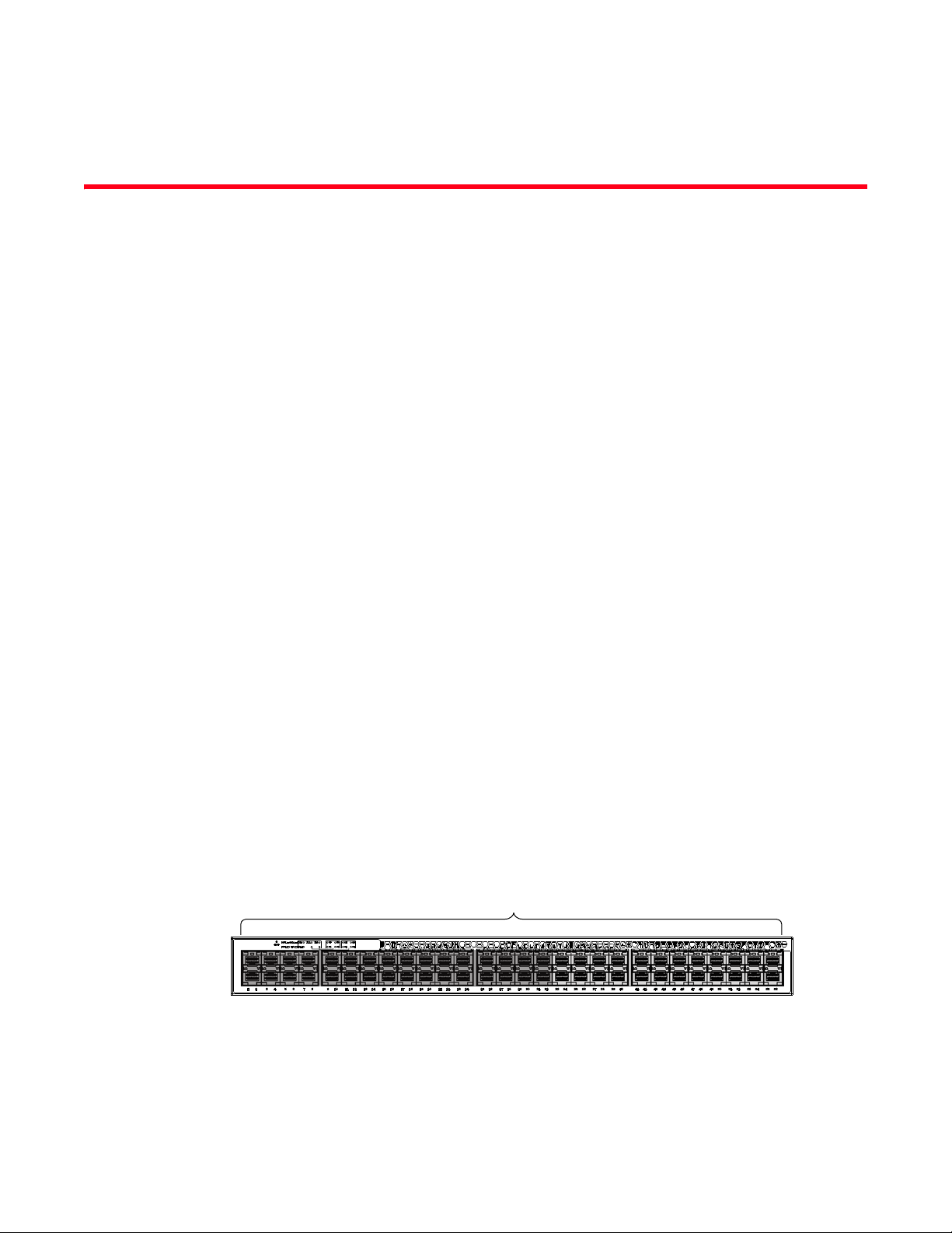
Brocade ICX 6650 slot and port numbering
Many CLI commands require users to enter port numbers as part of the command syntax, and
many show command outputs display port numbers. The port numbers are entered and displayed
in stack-unit/slot number/port number format. In all Brocade ICX 6650 inputs and outputs, the
stack-unit number is always 1.
The ICX 6650 contains the following slots and Ethernet ports:
• Slot 1 is located on the front of the ICX 6650 device and contains ports 1 through 56. Ports 1
through 32 are 10 GbE. Ports 33 through 56 are 1/10 GbE SFP+ ports. Refer to the following
figure.
Brocade ICX 6650 Administration Guide xiii
53-1002600-01
Page 14
Brocade ICX 6650 slot and port numbering
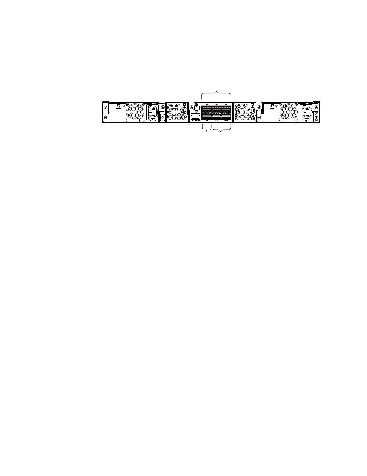
Slot 2
Slot 2 Slot 3
• Slot 2 is located on the back of the ICX 6650 device and contains ports 1 through 3 on the top
row and port 4 on the bottom row. These ports are 2x40 GbE QSFP+. Refer to the following
figure.
• Slot 3 is located on the back of the ICX 6650 device and contains ports 1 through 8. These
ports are 4 x 10 GbE breakout ports and require the use of a breakout cable. Refer to the
previous figure.
Document conventions
This section describes text formatting conventions and important notice formats used in this
document.
Text formatting
The narrative-text formatting conventions that are used are as follows:
bold text Identifies command names
Identifies the names of user-manipulated GUI elements
Identifies keywords and operands
Identifies text to enter at the GUI or CLI
italic text Provides emphasis
Identifies variables
Identifies paths and Internet addresses
Identifies document titles
code text Identifies CLI output
Identifies command syntax examples
For readability, command names in the narrative portions of this guide are presented in mixed
lettercase: for example, switchShow. In actual examples, command lettercase is all lowercase.
Command syntax conventions
Command syntax in this manual follows these conventions:
command Commands are printed in bold.
--option, option Command options are printed in bold.
-argument, arg Arguments.
Brocade ICX 6650 Administration Guide
53-1002600-01
Page 15
Brocade ICX 6650 slot and port numbering
NOTE
ATTENTION
CAUTION
DANGER
[ ] Optional elements appear in brackets.
variable Variables are printed in italics. In the help pages, values are underlined
enclosed in angled brackets < >.
... Repeat the previous element, for example “member[;member...]”
value Fixed values following arguments are printed in plain font. For example,
--show WWN
| Boolean. Elements are exclusive. Example:
--show -mode egress | ingress
or
Notes, cautions, and warnings
The following notices and statements are used in this manual. They are listed below in order of
increasing severity of potential hazards.
A note provides a tip, guidance, or advice, emphasizes important information, or provides a
reference to related information.
An Attention statement indicates potential damage to hardware or data.
A Caution statement alerts you to situations that can be potentially hazardous to you or cause
damage to hardware, firmware, software, or data.
A Danger statement indicates conditions or situations that can be potentially lethal or extremely
hazardous to you. Safety labels are also attached directly to products to warn of these conditions
or situations.
Notice to the reader
This document might contain references to the trademarks of the following corporations. These
trademarks are the properties of their respective companies and corporations.
These references are made for informational purposes only.
Corporation Referenced Trademarks and Products
Microsoft Corporation Windows, Windows NT, Internet Explorer
Oracle Corporation Oracle, Java
Netscape Communications Corporation Netscape
Mozilla Corporation Mozilla Firefox
Brocade ICX 6650 Administration Guide xv
53-1002600-01
Page 16

Brocade ICX 6650 slot and port numbering
Corporation Referenced Trademarks and Products
Sun Microsystems, Inc. Sun, Solaris
Red Hat, Inc. Red Hat, Red Hat Network, Maximum RPM, Linux Undercover
Related publications
The following Brocade documents supplement the information in this guide:
• Brocade ICX 6650 Release Notes
• Brocade ICX 6650 Hardware Installation Guide New
• Brocade ICX 6650 Administration Guide
• Brocade ICX 6650 Platform and Layer 2 Configuration Guide
• Brocade ICX 6650 Layer 3 Routing Configuration Guide
• Brocade ICX 6650 Security Configuration Guide
• Brocade ICX 6650 IP Multicast Configuration Guide
• Brocade ICX 6650 Diagnostic Reference
• Unified IP MIB Reference
• Ports-on-Demand Licensing for the Brocade ICX 6650
The latest versions of these guides are posted at http://www.brocade.com/ethernetproducts.
Additional information
This section lists additional Brocade and industry-specific documentation that you might find
helpful.
Brocade resources
To get up-to-the-minute information, go to http://my.brocade.com to register at no cost for a user
ID and password.
White papers, online demonstrations, and data sheets are available through the Brocade website
at:
http://www.brocade.com/products-solutions/products/index.page
For additional Brocade documentation, visit the Brocade website:
http://www.brocade.com
Release notes are available on the MyBrocade website.
Brocade ICX 6650 Administration Guide
53-1002600-01
Page 17

Other industry resources
For additional resource information, visit the Technical Committee T11 website. This website
provides interface standards for high-performance and mass storage applications for Fibre
Channel, storage management, and other applications:
http://www.t11.org
For information about the Fibre Channel industry, visit the Fibre Channel Industry Association
website:
http://www.fibrechannel.org
Getting technical help
To co n tact Techni c a l Support, go to
http://www.brocade.com/services-support/index.page
for the latest e-mail and telephone contact information.
Brocade ICX 6650 slot and port numbering
Document feedback
Quality is our first concern at Brocade and we have made every effort to ensure the accuracy and
completeness of this document. However, if you find an error or an omission, or you think that a
topic needs further development, we want to hear from you. Forward your feedback to:
documentation@brocade.com
Provide the title and version number of the document and as much detail as possible about your
comment, including the topic heading and page number and your suggestions for improvement.
Brocade ICX 6650 Administration Guide xvii
53-1002600-01
Page 18

Brocade ICX 6650 slot and port numbering
Brocade ICX 6650 Administration Guide
53-1002600-01
Page 19

Management Applications
In this chapter
•Management port overview . . . . . . . . . . . . . . . . . . . . . . . . . . . . . . . . . . . . . . . 1
•Logging on through the CLI . . . . . . . . . . . . . . . . . . . . . . . . . . . . . . . . . . . . . . . . 3
•Using slot number, and port number with CLI commands . . . . . . . . . . . . . . . 5
Tab le 1 lists the Brocade ICX 6650 switch and the management application features the switch
supports. These features are supported in full Layer 3 software images.
12
TABLE 1 Supported management application features
Feature Brocade ICX
Management port Yes
industry-standard Command Line
Interface (CLI), including support for:
• Serial and Telnet access
• Alias command
• On-line help
• Command completion
• Scroll control
• Line editing
• Searching and filtering output
• Special characters
1
6650
Yes
Management port overview
The management port is an out-of-band port that customers can use to manage their devices
without interfering with the in-band ports. The management port is widely used to download
images and configurations and for Telnet sessions.
How the management port works
The following rules apply to management ports:
• Only packets that are specifically addressed to the management port MAC address or the
broadcast MAC address are processed by the Layer 2 Switch or Layer 3 Switch. All other
packets are filtered out.
• No packet received on a management port is sent to any in-band ports, and no packets
received on in-band ports are sent to a management port.
• A management port is not part of any VLAN
• Protocols are not supported on the management port.
Brocade ICX 6650 Administration Guide 1
53-1002600-01
Page 20

Management port overview
1
• Creating a management VLAN disables the management port on the device.
For switches, any in-band port may be used for management purposes. A router sends Layer 3
packets using the MAC address of the port as the source MAC address.
CLI Commands for use with the management port
The following CLI commands can be used with a management port.
To display the current configuration, use the show running-config interface management
command.
Brocade(config-if-mgmt)#ip addr 10.44.9.64/24
Brocade(config)#show running-config interface management 1
interface management 1
ip address 10.44.9.64 255.255.255.0
Syntax: show running-config interface management <num>
To display the current configuration, use the show interfaces management command.
Brocade(config)#show interfaces management 1
GigEthernetmgmt1 is up, line protocol is up
Hardware is GigEthernet, address is 748e.f80c.5f40(bia 748e.f80c.5f40a)
Configured speed auto, actual 1Gbit, configured duplex fdx, actual fdx
Configured mdi mode AUTO, actual none
BPRU guard is disabled, ROOT protect is disabled
Link Error Dampening is Disabled
STP configured to OFF, priority is level0, mac-learning is enabled
Flow Control is config disabled, oper enabled
Mirror disabled, Monitor disabled
Not member of any active trunks
Not member of any configured trunks
No port name
IPG MII 0 bits-time, IPG GMII 0 bits-time
IP MTU 1500 bytes
300 second input rate: 83728 bits/sec, 130 packets/sec, 0.01% utilization
300 second output rate: 24 bits/sec, 0 packets/sec, 0.00% utilization
39926 packets input, 3210077 bytes, 0 no buffer
Received 4353 broadcasts, 32503 multicasts, 370 unicasts
0 input errors, 0 CRC, 0 frame, 0 ignored
0 runts, 0 giants
22 packets output, 1540 bytres, 0 underruns
Transmitted 0 broadcasts, 6 multicasts, 16 unicasts
0 output errors, 0 collisions
Syntax: show interfaces management <num>
To display the management interface information in brief form, enter the show interfaces brief
management command.
Brocade(config)#show interfaces brief management 1
Port Link State Dupl Speed Trunk Tag Pri MAC Name
mgmt1 Up None Full 1G None No 0 748e.f80c.5f40
Syntax: show interfaces brief management <num>
2 Brocade ICX 6650 Administration Guide
53-1002600-01
Page 21

Logging on through the CLI
To display management port statistics, enter the show statistics management command.
Brocade(config)#show statistics management 1
Port Link State Dupl Speed Trunk Tag Pri MAC Name
mgmt1 Up None Full 1G None No 0 748e.f80c.5f40
Port mgmt1 Counters:
InOctets3210941OutOctets1540
InPkts39939OutPackets22
InBroadcastPkts4355OutbroadcastPkts0
InMultiastPkts35214OutMulticastPkts6
InUnicastPkts370OutUnicastPkts16
InBadPkts0
InFragments0
InDiscards0OutErrors0
CRC 0 Collisions0
InErrors0 LateCollisions0
InGiantPkts0
InShortPkts0
InJabber0
InFlowCtrlPkts0OutFlowCtrlPkts0
InBitsPerSec83728OutBitsPerSec24
InPktsPerSec130OutPktsPerSec0
InUtilization0.01%OutUtilization0.00%
1
Syntax: show statistics management <num>
To display the management interface statistics in brief form, enter the show statistics brief
management command.
Brocade(config)#show statistics brief management 1
PortIn PacketsOut PacketsTrunkIn ErrorsOut Errors
mgmt1399462200
Total399452200
Syntax: show statistics brief management <num>
Logging on through the CLI
Once an IP address is assigned to a Brocade device running Layer 2 software or to an interface on
the Brocade device running Layer 3 software, you can access the CLI either through the direct
serial connection to the device or through a local or remote Telnet session.
You can initiate a local Telnet or SNMP connection by attaching a cable to a port and specifying the
assigned management station IP address.
The commands in the CLI are organized into the following levels:
• User EXEC – Lets you display information and perform basic tasks such as pings and
traceroutes.
• Privileged EXEC – Lets you use the same commands as those at the User EXEC level plus
configuration commands that do not require saving the changes to the system-config file.
Brocade ICX 6650 Administration Guide 3
53-1002600-01
Page 22

Logging on through the CLI
NOTE
1
• CONFIG – Lets you make configuration changes to the device. To save the changes across
reboots, you need to save them to the system-config file. The CONFIG level contains sub-levels
for individual ports, for VLANs, for routing protocols, and other configuration areas.
By default, any user who can open a serial or Telnet connection to the Brocade device can access
all these CLI levels. To secure access, you can configure Enable passwords or local user accounts,
or you can configure the device to use a RADIUS or TACACS/TACACS+ server for authentication. refer
to the Brocade ICX 6650 Switch Security Configuration Guide.
Online help
To display a list of available commands or command options, enter “?” or press Tab. If you have
not entered part of a command at the command prompt, all the commands supported at the
current CLI level are listed. If you enter part of a command, then enter “?” or press Tab, the CLI
lists the options you can enter at this point in the command string.
If you enter an invalid command followed by ?, a message appears indicating the command was
unrecognized. An example is given below.
Brocade(config)#rooter ip
Unrecognized command
Command completion
The CLI supports command completion, so you do not need to enter the entire name of a command
or option. As long as you enter enough characters of the command or option name to avoid
ambiguity with other commands or options, the CLI understands what you are typing.
Scroll control
By default, the CLI uses a page mode to paginate displays that are longer than the number of rows
in your terminal emulation window. For example, if you display a list of all the commands at the
global CONFIG level but your terminal emulation window does not have enough rows to display
them all at once, the page mode stops the display and lists your choices for continuing the display.
An example is given below.
aaa
all-client
appletalk
arp
boot
some lines omitted for brevity...
ipx
lock-address
logging
mac
--More--, next page: Space, next line:
Return key, quit: Control-c
The software provides the following scrolling options:
• Press the Space bar to display the next page (one screen at a time).
4 Brocade ICX 6650 Administration Guide
53-1002600-01
Page 23

Using slot number, and port number with CLI commands
1
• Press the Return or Enter key to display the next line (one line at a time).
• Press Ctrl+C or Ctrl+Q to cancel the display.
Line editing commands
The CLI supports the following line editing commands. To enter a line-editing command, use the
CTRL+key combination for the command by pressing and holding the CTRL key, then pressing the
letter associated with the command.
TABLE 2 CLI line editing commands
Ctrl+Key combination Description
Ctrl+A Moves to the first character on the command line.
Ctrl+B Moves the cursor back one character.
Ctrl+C Escapes and terminates command prompts and ongoing tasks (such as
lengthy displays), and displays a fresh command prompt.
Ctrl+D Deletes the character at the cursor.
Ctrl+E Moves to the end of the current command line.
Ctrl+F Moves the cursor forward one character.
Ctrl+K Deletes all characters from the cursor to the end of the command line.
Ctrl+L; Ctrl+R Repeats the current command line on a new line.
Ctrl+N Enters the next command line in the history buffer.
Ctrl+P Enters the previous command line in the history buffer.
Ctrl+U; Ctrl+X Deletes all characters from the cursor to the beginning of the command line.
Ctrl+W Deletes the last word you typed.
Ctrl+Z Moves from any CONFIG level of the CLI to the Privileged EXEC level; at the
Privileged EXEC level, moves to the User EXEC level.
Using slot number, and port number
with CLI commands
Many CLI commands require users to enter port numbers as part of the command syntax, and
many show command outputs display port numbers. The port numbers are entered in the
following format: stack-unit/slot/port.
The ports are labelled on the front panels of the devices.
Brocade ICX 6650 Administration Guide 5
53-1002600-01
Page 24

Using slot number, and port number with CLI commands
NOTE
Internet address is 192.168.1.11/24, MTU 1518 bytes, encapsulation ethernet
1
CLI nomenclature on Brocade ICX 6650 models
When you enter CLI commands that include the port number as part of the syntax, you must use
the stack unit/slot number/port number format. The unit number is 1. For example, the following
commands change the CLI from the global CONFIG level to the configuration level for the first port
on the device:
Brocade(config)#interface ethernet 1/1/1
Brocade(config-if-e1000-1/1/1)#
Syntax: ethernet <stack-unit>/<slot>/<port>
Searching and filtering output from CLI commands
You can filter CLI output from show commands and at the --More-- prompt. You can search for
individual characters, strings, or construct complex regular expressions to filter the output.
Searching and filtering output from Show commands
You can filter output from show commands to display lines containing a specified string, lines that
do not contain a specified string, or output starting with a line containing a specified string. The
search string is a regular expression consisting of a single character or string of characters. You
can use special characters to construct complex regular expressions. Refer to “Using special
characters in regular expressions” on page 8 for information on special characters used with
regular expressions.
Displaying lines containing a specified string
The following command filters the output of the show interface command for port 1/1/2 so it
displays only lines containing the word “Internet”. This command can be used to display the IP
address of the interface.
Syntax: <show-command> | include <regular-expression>
The vertical bar ( | ) is part of the command.
Note that the regular expression specified as the search string is case sensitive. In the example
above, a search string of “Internet” would match the line containing the IP address, but a search
string of “internet” would not.
Displaying lines that do not contain a specified string
The following command filters the output of the show who command so it displays only lines that
do not contain the word “closed”. This command can be used to display open connections to the
Brocade device.
6 Brocade ICX 6650 Administration Guide
53-1002600-01
Page 25

Using slot number, and port number with CLI commands
Brocade#show who | exclude closed
Console connections:
established
you are connecting to this session
2 seconds in idle
Telnet connections (inbound):
1 established, client ip address 192.168.9.37
27 seconds in idle
Telnet connection (outbound):
SSH connections:
Brocade#show who | begin SSH
SSH connections:
1 established, client ip address 192.168.9.210
7 seconds in idle
2 closed
3 closed
4 closed
5 closed
--More--, next page: Space, next line: Return key, quit: Control-c
/telnet
The results of the search are displayed.
searching...
telnet Telnet by name or IP address
temperature temperature sensor commands
terminal display syslog
traceroute TraceRoute to IP node
undebug Disable debugging functions (see also 'debug')
undelete Undelete flash card files
whois WHOIS lookup
write Write running configuration to flash or terminal
1
Syntax: <show-command> | exclude <regular-expression>
Displaying lines starting with a specified string
The following command filters the output of the show who command so it displays output starting
with the first line that contains the word “SSH”. This command can be used to display information
about SSH connections to the Brocade device.
Syntax: <show-command> | begin <regular-expression>
Searching and filtering output at the --More-- prompt
The --More-- prompt displays when output extends beyond a single page. From this prompt, you can
press the Space bar to display the next page, the Return or Enter key to display the next line, or
Ctrl+C or Q to cancel the display. In addition, you can search and filter output from this prompt.
At the --More-- prompt, you can press the forward slash key ( / ) and then enter a search string. The
Brocade device displays output starting from the first line that contains the search string, similar to
the begin option for show commands. An example is given below.
Brocade ICX 6650 Administration Guide 7
53-1002600-01
Page 26

Using slot number, and port number with CLI commands
--More--, next page: Space, next line: Return key, quit: Control-c
+telnet
filtering...
telnet Telnet by name or IP address
--More--, next page: Space, next line: Return key, quit: Control-c
-telnet
filtering...
temperature temperature sensor commands
terminal display syslog
traceroute TraceRoute to IP node
undebug Disable debugging functions (see also 'debug')
undelete Undelete flash card files
whois WHOIS lookup
write Write running configuration to flash or terminal
1
To display lines containing only a specified search string (similar to the include option for show
commands) press the plus sign key ( + ) at the --More-- prompt and then enter the search string.
The filtered results are displayed.
To display lines that do not contain a specified search string (similar to the exclude option for show
commands) press the minus sign key ( - ) at the --More-- prompt and then enter the search string.
The filtered results are displayed.
As with the commands for filtering output from show commands, the search string is a regular
expression consisting of a single character or string of characters. You can use special characters
to construct complex regular expressions. See the next section for information on special
characters used with regular expressions.
Using special characters in regular expressions
You use a regular expression to specify a single character or multiple characters as a search string.
In addition, you can include special characters that influence the way the software matches the
output against the search string. These special characters are listed in the following table.
TABLE 3 Special characters for regular expressions
Character Operation
. The period matches on any single character, including a blank space.
For example, the following regular expression matches “aaz”, “abz”, “acz”, and so on, but not just
“az”:
a.z
* The asterisk matches on zero or more sequential instances of a pattern.
For example, the following regular expression matches output that contains the string “abc”,
followed by zero or more Xs:
abcX*
8 Brocade ICX 6650 Administration Guide
53-1002600-01
Page 27

Using slot number, and port number with CLI commands
TABLE 3 Special characters for regular expressions (Continued)
Character Operation
+ The plus sign matches on one or more sequential instances of a pattern.
For example, the following regular expression matches output that contains "de", followed by a
sequence of “g”s, such as “deg”, “degg”, “deggg”, and so on:
deg+
? The question mark matches on zero occurrences or one occurrence of a pattern.
For example, the following regular expression matches output that contains "dg" or "deg":
de?g
NOTE: Normally when you type a question mark, the CLI lists the commands or options at that CLI
level that begin with the character or string you entered. However, if you enter Ctrl+V and
then type a question mark, the question mark is inserted into the command line, allowing
you to use it as part of a regular expression.
^ A caret (when not used within brackets) matches on the beginning of an input string.
For example, the following regular expression matches output that begins with “deg”:
^deg
$ A dollar sign matches on the end of an input string.
For example, the following regular expression matches output that ends with “deg”:
deg$
_ An underscore matches on one or more of the following:
• , (comma)
• { (left curly brace)
• } (right curly brace)
• ( (left parenthesis)
• ) (right parenthesis)
• The beginning of the input string
• The end of the input string
• A blank space
For example, the following regular expression matches on “100” but not on “1002”, “2100”, and
so on.
_100_
[ ] Square brackets enclose a range of single-character patterns.
For example, the following regular expression matches output that contains “1”, “2”, “3”, “4”, or
“5”:
[1-5]
You can use the following expression symbols within the brackets. These symbols are allowed
only inside the brackets.
• ^ – The caret matches on any characters except the ones in the brackets. For example, the
following regular expression matches output that does not contain “1”, “2”, “3”, “4”, or “5”:
1
[^1-5]
• - The hyphen separates the beginning and ending of a range of characters. A match occurs if
any of the characters within the range is present. See the example above.
| A vertical bar separates two alternative values or sets of values. The output can match one or the
other value.
For example, the following regular expression matches output that contains either “abc” or “defg”:
abc|defg
( ) Parentheses allow you to create complex expressions.
For example, the following complex expression matches on “abc”, “abcabc”, or “defg”, but not on
“abcdefgdefg”:
((abc)+)|((defg)?)
Brocade ICX 6650 Administration Guide 9
53-1002600-01
Page 28

Using slot number, and port number with CLI commands
1
If you want to filter for a special character instead of using the special character as described in the
table above, enter “\” (backslash) in front of the character. For example, to filter on output
containing an asterisk, enter the asterisk portion of the regular expression as “\*”.
Brocade#show ip route bgp | include \*
Creating an alias for a CLI command
You can cre ate aliases for CLI commands. An alias serves as a shorthand version of a longer CLI
command. For example, you can create an alias called shoro for the CLI command show ip route.
Then when you enter shoro at the command prompt, the show ip route command is executed.
To create an alias called shoro for the CLI command show ip route, enter the alias shoro = show ip
route command.
Brocade(config)#alias shoro = show ip route
Syntax: [no] alias <alias-name> = <cli-command>
The <alias-name> must be a single word, without spaces.
After the alias is configured, entering shoro at either the Privileged EXEC or CONFIG levels of the
CLI, executes the show ip route command.
To create an alias called wrsbc for the CLI command copy running-config tftp 10.10.10.10 test.cfg,
enter the following command.
Brocade(config)#alias wrsbc = copy running-config tftp 10.10.10.10 test.cfg
To re m ove the wrsbc alias from the configuration, enter one of the following commands.
Brocade(config)#no alias wrsbc
or
Brocade(config)#unalias wrsbc
Syntax: unalias <alias-name>
The specified <alias-name> must be the name of an alias already configured on the Brocade
device.
To display the aliases currently configured on the Brocade device, enter the following command at
either the Privileged EXEC or CONFIG levels of the CLI.
Brocade#alias
wrsbc copy running-config tftp 10.10.10.10 test.cfg
shoro show ip route
Syntax: alias
Configuration notes for creating a command alias
The following configuration notes apply to this feature:
• You cannot include additional parameters with the alias at the command prompt. For
example, after you create the shoro alias, shoro bgp would not be a valid command.
10 Brocade ICX 6650 Administration Guide
53-1002600-01
Page 29

Using slot number, and port number with CLI commands
• If configured on the Brocade device, authentication, authorization, and accounting is
performed on the actual command, not on the alias for the command.
• To save an alias definition to the startup-config file, use the write memory command.
1
Brocade ICX 6650 Administration Guide 11
53-1002600-01
Page 30

Using slot number, and port number with CLI commands
1
12 Brocade ICX 6650 Administration Guide
53-1002600-01
Page 31

Chapter
Basic Software Features
In this chapter
•Basic system parameter configuration . . . . . . . . . . . . . . . . . . . . . . . . . . . . . 14
•Specifying an SNTP server . . . . . . . . . . . . . . . . . . . . . . . . . . . . . . . . . . . . . . . 20
•Configuring the device as an SNTP server. . . . . . . . . . . . . . . . . . . . . . . . . . . 23
•Basic port parameter configuration . . . . . . . . . . . . . . . . . . . . . . . . . . . . . . . . 31
Tab le 4 lists the Brocade ICX 6650 switch and the basic software features the switch supports.
These features are supported in full Layer 3 software images, except where explicitly noted.
TABLE 4 Supported basic software features
Feature Brocade ICX
Basic System Parameters
System name, contact, and location Yes
SNMP trap receiver and trap source
address
Virtual routing interface statistics via
SNMP
Disable Syslog messages and traps for CLI
access
Cancelling an outbound Telnet session Yes
System time using a Simple Network Time
Protocol (SNTP) server or local system
counter
Enabling broadcast mode for SNTP client Yes
System clock Yes
Packet-based broadcast, multicast, and
unknown-unicast limits
CLI banners Yes
Local MAC address for Layer 2
management traffic
Basic Port Parameters
2
6650
Yes
Yes
Yes
Yes
Yes
Yes
Port name Yes
10/100/1000 port speed Yes
Auto-negotiation Yes
Auto-negotiation maximum port speed
advertisement and down-shift
Brocade ICX 6650 Administration Guide 13
53-1002600-01
Yes
Page 32

Basic system parameter configuration
NOTE
NOTE
NOTE
2
TABLE 4 Supported basic software features
Feature Brocade ICX
Duplex mode Yes
Port status (enable or disable) Yes
Flow control:
• Responds to flow control packets,
but does not generate them
Symmetric flow control
• Can transmit and receive 802.3x
PAUSE f rames
Auto-negotiation and advertisement of
flow control
Interpacket Gap (IPG) adjustment Yes
Gbps fiber negotiate mode Yes
QoS priority Yes
Port flap dampening Yes
Port loop detection Yes
6650
Yes
Yes
Yes
Basic system parameter configuration
Brocade devices are configured at the factory with default parameters that allow you to begin using
the basic features of the system immediately. However, many of the advanced features such as
VLANs or routing protocols for the device must first be enabled at the system (global) level before
they can be configured. If you use the Command Line Interface (CLI) to configure system
parameters, you can find these system level parameters at the Global CONFIG level of the CLI.
Before assigning or modifying any router parameters, you must assign the IP subnet (interface)
addresses for each port.
For information about configuring IP addresses, DNS resolver, DHCP assist, and other IP-related
parameters, refer to the Brocade ICX 6650 Switch Layer 3 Routing Configuration Guide.
For information about the Syslog buffer and messages, refer to Appendix A, “Syslog messages”.
The procedures in this section describe how to configure the basic system parameters listed in
Tab le 4.
14 Brocade ICX 6650 Administration Guide
53-1002600-01
Page 33

Basic system parameter configuration
NOTE
NOTE
2
Entering system administration information
You can configure a system name, contact, and location for a Brocade device and save the
information locally in the configuration file for future reference. This information is not required for
system operation but is suggested. When you configure a system name, the name replaces the
default system name in the CLI command prompt.
The name, contact, and location each can be up to 255 alphanumeric characters.
Here is an example of how to configure a system name, system contact, and location.
Brocade(config)# hostname zappa
zappa(config)# snmp-server contact Support Services
zappa(config)# snmp-server location Centerville
zappa(config)# end
zappa# write memory
Syntax: hostname <string>
Syntax: snmp-server contact <string>
Syntax: snmp-server location <string>
The text strings can contain blanks. The SNMP text strings do not require quotation marks when
they contain blanks but the host name does.
The chassis name command does not change the CLI prompt. Instead, the command assigns an
administrative ID to the device.
SNMP parameter configuration
Use the procedures in this section to perform the following configuration tasks:
• Specify a Simple Network Management Protocol (SNMP) trap receiver.
• Specify a source address and community string for all traps sent by the device.
• Change the holddown time for SNMP traps
• Disable individual SNMP traps. (All traps are enabled by default.)
• Disable traps for CLI access that is authenticated by a local user account, a RADIUS server, or
a TACACS/TACACS+ server.
To add and modify “get” (read-only) and “set” (read-write) community strings, refer to the Brocade
ICX 6650 Switch Security Configuration Guide.
Specifying an SNMP trap receiver
You can specify a trap receiver to ensure that all SNMP traps sent by the Brocade device go to the
same SNMP trap receiver or set of receivers, typically one or more host devices on the network.
When you specify the host, you also specify a community string. The Brocade device sends all the
SNMP traps to the specified hosts and includes the specified community string. Administrators
can therefore filter for traps from a Brocade device based on IP address or community string.
Brocade ICX 6650 Administration Guide 15
53-1002600-01
Page 34

Basic system parameter configuration
2
When you add a trap receiver, the software automatically encrypts the community string you
associate with the receiver when the string is displayed by the CLI. If you want the software to show
the community string in the clear, you must explicitly specify this when you add a trap receiver. In
either case, the software does not encrypt the string in the SNMP traps sent to the receiver.
To specify the host to which the device sends all SNMP traps, use one of the following methods.
To add a trap receiver and encrypt the display of the community string, enter commands such as
the following.
To specify an SNMP trap receiver and change the UDP port that will be used to receive traps, enter
a command such as the following.
Brocade(config)# snmp-server host 2.2.2.2 0 mypublic port 200
Brocade(config)# write memory
Syntax: snmp-server host <ip-addr> [0 | 1] <string> [port <value>]
The <ip-addr> parameter specifies the IP address of the trap receiver.
The 0 | 1 parameter specifies whether you want the software to encrypt the string (1) or show the
string in the clear (0). The default is 0.
The <string> parameter specifies an SNMP community string configured on the Brocade device.
The string can be a read-only string or a read-write string. The string is not used to authenticate
access to the trap host but is instead a useful method for filtering traps on the host. For example,
if you configure each of your Brocade devices that use the trap host to send a different community
string, you can easily distinguish among the traps from different Brocade devices based on the
community strings.
The command in the example above adds trap receiver 2.2.2.2 and configures the software to
encrypt display of the community string. When you save the new community string to the
startup-config file (using the write memory command), the software adds the following command
to the file.
snmp-server host 2.2.2.2 1 <encrypted-string>
To add a trap receiver and configure the software to encrypt display of the community string in the
CLI , enter commands such as the following.
Brocade(config)# snmp-server host 2.2.2.2 0 FastIron-12
Brocade(config)# write memory
The port <value> parameter allows you to specify which UDP port will be used by the trap receiver.
This parameter allows you to configure several trap receivers in a system. With this parameter, a
network management application can coexist in the same system. Brocade devices can be
configured to send copies of traps to more than one network management application.
Specifying a single trap source
You can specify a single trap source to ensure that all SNMP traps sent by the Layer 3 switch use
the same source IP address. For configuration details, refer to the Brocade ICX 6650 Switch Layer
3 Routing Configuration Guide.
16 Brocade ICX 6650 Administration Guide
53-1002600-01
Page 35

Basic system parameter configuration
NOTE
2
Setting the SNMP trap holddown time
When a Brocade device starts up, the software waits for Layer 2 convergence (STP) and Layer 3
convergence (OSPF) before beginning to send SNMP traps to external SNMP servers. Until
convergence occurs, the device might not be able to reach the servers, in which case the messages
are lost.
By default, a Brocade device uses a one-minute holddown time to wait for the convergence to occur
before starting to send SNMP traps. After the holddown time expires, the device sends the traps,
including traps such as “cold start” or “warm start” that occur before the holddown time expires.
You can change the holddown time to a value from one second to ten minutes.
To change the holddown time for SNMP traps, enter a command such as the following at the global
CONFIG level of the CLI.
Brocade(config)# snmp-server enable traps holddown-time 30
The command in this example changes the holddown time for SNMP traps to 30 seconds. The
device waits 30 seconds to allow convergence in STP and OSPF before sending traps to the SNMP
trap receiver.
Syntax: [no] snmp-server enable traps holddown-time <secs>
The <secs> parameter specifies the number of seconds and can be from 1 – 600 (ten minutes).
The default is 60 seconds.
Disabling SNMP traps
Brocade devices come with SNMP trap generation enabled by default for all traps. You can
selectively disable one or more of the following traps.
By default, all SNMP traps are enabled at system startup.
SNMP Layer 2 traps
The following traps are generated on devices running Layer 2 software:
• SNMP authentication keys
• Power supply failure
• Fan failure
• Cold start
• Link up
• Link down
• Bridge new root
• Bridge topology change
• Locked address violation
SNMP Layer 3 traps
The following traps are generated on devices running Layer 3 software:
• SNMP authentication key
Brocade ICX 6650 Administration Guide 17
53-1002600-01
Page 36

Basic system parameter configuration
2
• Power supply failure
• Fan failure
• Cold start
• Link up
• Link down
• Bridge new root
• Bridge topology change
• Locked address violation
• BGP4
• OSPF
• VRRP
• VRRP-E
To stop link down occurrences from being reported, enter the following.
Brocade(config)# no snmp-server enable traps link-down
Syntax: [no] snmp-server enable traps <trap-type>
Displaying virtual routing interface statistics
You can enable SNMP to extract and display virtual routing interface statistics from the ifXTable
(64-bit counters).
The following describes the limitations of this feature:
• The Brocade device counts traffic from all virtual interfaces (VEs). For example, in a
configuration with two VLANs (VLAN 1 and VLAN 20) on port 1, when traffic is sent on VLAN 1,
the counters (VE statistics) increase for both VE 1 and VE 20.
• The counters include all traffic on each virtual interface, even if the virtual interface is
disabled.
• The counters include traffic that is denied by ACLs or MAC address filters.
To enable SNMP to display VE statistics, enter the enable snmp ve-statistics command.
Brocade(config)# enable snmp ve-statistics
Syntax: [no] enable snmp ve-statistics
Use the no form of the command to disable this feature once it is enabled.
Note that the above CLI command enables SNMP to display virtual interface statistics. It does not
enable the CLI to display the statistics.
Disabling Syslog messages and traps for CLI access
Brocade devices send Syslog messages and SNMP traps when a user logs into or out of the User
EXEC or Privileged EXEC level of the CLI. The feature applies to users whose access is
authenticated by an authentication-method list based on a local user account, RADIUS server, or
TACACS/TACACS+ server.
18 Brocade ICX 6650 Administration Guide
53-1002600-01
Page 37

Basic system parameter configuration
NOTE
NOTE
Brocade# show logging
Syslog logging: enabled (0 messages dropped, 0 flushes, 0 overruns)
Buffer logging: level ACDMEINW, 12 messages logged
level code: A=alert C=critical D=debugging M=emergency E=error
I=informational N=notification W=warning
Static Log Buffer:
Dec 15 19:04:14:A:Fan 1, fan on right connector, failed
Dynamic Log Buffer (50 entries):
Oct 15 18:01:11:info:dg logout from USER EXEC mode
Oct 15 17:59:22:info:dg logout from PRIVILEGE EXEC mode
Oct 15 17:38:07:info:dg login to PRIVILEGE EXEC mode
Oct 15 17:38:03:info:dg login to USER EXEC mode
2
The Privileged EXEC level is sometimes called the “Enable” level, because the command for
accessing this level is enable.
The feature is enabled by default.
Examples of Syslog messages for CLI access
When a user whose access is authenticated by a local user account, a RADIUS server, or a TACACS
or TACACS+ server logs into or out of the CLI User EXEC or Privileged EXEC mode, the software
generates a Syslog message and trap containing the following information:
• The time stamp
• The user name
• Whether the user logged in or out
• The CLI level the user logged into or out of (User EXEC or Privileged EXEC level)
Messages for accessing the User EXEC level apply only to access through Telnet. The device does
not authenticate initial access through serial connections but does authenticate serial access to the
Privileged EXEC level. Messages for accessing the Privileged EXEC level apply to access through the
serial connection or Telnet.
The following examples show login and logout messages for the User EXEC and Privileged EXEC
levels of the CLI.
Syntax: show logging
The first message (the one on the bottom) indicates that user “dg” logged in to the CLI User EXEC
level on October 15 at 5:38 PM and 3 seconds (Oct 15 17:38:03). The same user logged into the
Privileged EXEC level four seconds later.
The user remained in the Privileged EXEC mode until 5:59 PM and 22 seconds. (The user could
have used the CONFIG modes as well. Once you access the Privileged EXEC level, no further
authentication is required to access the CONFIG levels.) At 6:01 PM and 11 seconds, the user
ended the CLI session.
Disabling the Syslog messages and traps
Logging of CLI access is enabled by default. If you want to disable the logging, enter the following
commands.
Brocade ICX 6650 Administration Guide 19
53-1002600-01
Page 38

Specifying an SNTP server
NOTE
2
Brocade(config)# no logging enable user-login
Brocade(config)# write memory
Brocade(config)# end
Brocade# reload
Syntax: [no] logging enable user-login
Cancelling an outbound Telnet session
If you want to cancel a Telnet session from the console to a remote Telnet server (for example, if the
connection is frozen), you can terminate the Telnet session by doing the following.
1. At the console, press Ctrl+^ (Ctrl+Shift-6).
2. Press the X key to terminate the Telnet session.
Pressing Ctrl+^ twice in a row causes a single Ctrl+^ character to be sent to the Telnet server. After
you press Ctrl+^, pressing any key other than X or Ctrl+^ returns you to the Telnet session.
Specifying an SNTP server
The Brocade device can be configured as a Simple Network Time Protocol (SNTP) client. You can
configure the Brocade device to consult up to three SNTP servers for the current system time and
date. The first server configured will be used unless it becomes unreachable, in which case the
Brocade device will attempt to synchronize with the other SNTP servers (if any) in the order in which
they were configured.
Brocade devices do not retain time and date information across power cycles. Unless you want to
reconfigure the system time counter each time the system is reset, Brocade recommends that you
use the SNTP feature as described below.
To identify an SNTP server with IP address 10.99.8.95 to act as the clock reference for a Brocade
device, enter the following.
Brocade(config)# sntp server 10.99.8.95
Syntax: [no] sntp server { <ip-address> | <hostname> | ipv6 <ipv6-address> } [<sntp-version>] [
authentication-key <key-ID> <key-string>]
The <sntp-version> parameter specifies the SNTP version the server is running and can be from 1
– 4. The default is 4. The SNTP version is automatically set to 4, unless a different SNTP version is
specified in the device startup configuration. You can configure up to three SNTP servers by
entering three separate sntp server commands.
The order in which the SNTP servers are configured is the order in which they are consulted. The
server that was configured first is the first server consulted after the poll cycle; the next server will
be consulted only if a positive ACK is not received from the first one.
To specify an IPv6 address for the SNTP server, use the ipv6 option.
20 Brocade ICX 6650 Administration Guide
53-1002600-01
Page 39

Specifying an SNTP server
Brocade# show sntp associations
address ref clock st when poll delay disp
~10.95.6.102 0.0.0.0 16 202 4 0.0 5.45
~10.95.6.101 0.0.0.0 16 202 0 0.0 0.0
* synced, ~ configured
2
The authentication-key option allows you to configure an authentication key for communication
with the SNTP server. When the authentication key is configured for an SNTP client, it is used only
for an SNTP unicast client. You must assign a unique server <key-ID> and pre-share <key-string>.
The <key-ID> and pre-share <key-string> are used together to create the MD5 checksum. The MD5
checksum is used for authentication for request and reply messages with the SNTP server. The
<key-ID> is the symmetric key shared with the upstream server, and accepts values from 1 to
4,294,967,295. The <key-string> is the authentication string itself, and can take up to 16
characters. If the <key-string> variable consists of only numerical characters, you must enclose the
numerical characters in double quotes.
Modification of the authentication key fields is not supported. To change the key ID or key string,
remove the time server using the no sntp server... command, then reconfigure the server with the
new key.
By default, the Brocade device polls its SNTP server every 30 minutes (1800 seconds). To
configure the Brocade device to poll for clock updates from a SNTP server every 15 minutes, enter
the following.
Brocade(config)# sntp poll-interval 900
Syntax: [no] sntp poll-interval <16-131072>
To display information about SNTP associations, enter the show sntp associations command.
Syntax: show sntp associations
The following table describes the information displayed by the show sntp associations command.
TABLE 5 Output from the show sntp associations command
Field Description
(leading character) One or both of the following:
*Synchronized to this peer
~ Peer is statically configured
address IP address of the peer
ref clock IP address of the peer reference clock, or the reference ID of the
external clock source if the peer is stratum 1.
Examples of external clock source IDs: GPS, CDMA, WWV (Ft.Collins US
Radio 2.5, 5, 10, 15 MHz), CESM (calibrated Cesium clock), etc.
st NTP stratum level of the peer
when Amount of time since the last NTP packet was received from the peer. A
negative number indicates the system has never received any
synchronization message from the specified server.
poll The poll interval of the peer relative to the server.
delay The total delay time in milliseconds along the path to the root clock.
disp The dispersion of the root path in milliseconds.
Brocade ICX 6650 Administration Guide 21
53-1002600-01
Page 40

Specifying an SNTP server
Brocade# show sntp associations details
10.99.8.95 configured,insane, unsynched,invalid, stratum 16
ref ID 0.0.0.0,time 0.0 (Jan 1 00:00:00)
our mode client, peer mode unspec, our poll intvl 15, peer poll intvl 0
root delay 0.0 msec, root disp 0.0
delay 0 msec, offset 0 msec
precision 2**0, version 0
org time 0.0 (Jan 1 00:00:00)
rcv time 0.0 (Jan 1 00:00:00)
xmt time 0.0 (Jan 1 00:00:00)
2
To display detailed information about SNTP associations, enter the show sntp associations details
command.
Syntax: show sntp associations details
The following table describes the information displayed by the show sntp associations details
command.
TABLE 6 Output from the show sntp associations details command
Field Description
IP address The IP address of the SNTP server. The IP address is an IPv4 or an IPv6
address.
configured or dynamic The SNTP server is either configured, or the last responsive broadcast
server that is found dynamically.
authenticated If MD5 authentication is enabled for the peer.
sane or insane If the SNTP server passes sanity checks.
synched or unsynched If the system is synchronized or unsynchronized to the NTP peer.
valid or invalid If the peer time is valid or invalid.
stratum The NTP stratum level of the peer.
reference ID The IP address of the peer (if any) to which the unit is synchronized. The
reference ID can also refer to the external clock source if the peer is
stratum 1.
Examples of external clock source IDs: GPS, CDMA, WWV (Ft.Collins US
Radio 2.5, 5, 10, 15 MHz), CESM (calibrated Cesium clock), etc.
time The reference time stamp.
our mode The mode relative to the peer. The mode can be a client or a broadcast
client.
peer mode Peer mode relative to us.
our poll intvl The system poll interval relative to the peer.
peer poll intv The poll interval of the peer relative to the server.
root delay The total delay time in milliseconds along the path to the root clock.
22 Brocade ICX 6650 Administration Guide
root disp The dispersion of the root path in milliseconds.
delay The round trip delay to the peer in milliseconds.
offset The offset of the peer clock relative to the system clock.
53-1002600-01
Page 41

Configuring the device as an SNTP server
Brocade# show sntp status
Clock is synchronized, stratum = 4, reference clock = 10.70.20.23
precision is 2**-20
reference time is 3489354594.3780510747
clock offset is 0.0000 msec, root delay is 0.41 msec
root dispersion is 0.11 msec, peer dispersion is 0.00 msec
sntp poll-interval is 10 secs
Field Description
precision The precision of the system clock in Hz.
version The NTP version of the peer. The version can be from 1 - 4.
org time The original timestamp of the system clock. The original timestamp is
what the client has sent to the server.
rcv time The receive timestamp of the system clock.
xmt time The transmit timestamp of the system clock.
To display information about SNTP status, enter the show sntp status command.
Syntax: show sntp status
2
The following table describes the information displayed by the show sntp status command.
TABLE 7 Output from the show sntp status command
Field Description
unsynchronized System is not synchronized to an NTP peer.
synchronized System is synchronized to an NTP peer.
stratum NTP stratum level of the upstream time server.
reference clock IP address of the peer reference clock, or the reference ID of the
external clock source if the peer is stratum 1.
Examples of external clock source IDs: GPS, CDMA, WWV (Ft.Collins US
Radio 2.5, 5, 10, 15 MHz), CESM (calibrated Cesium clock), etc.
precision Precision of this system's clock (in Hz)
reference time Reference time stamp
clock offset Offset of clock to synchronized peer
root delay Total delay along the path to the root clock
root dispersion Dispersion of the root path
peer dispersion Dispersion of the synchronized peer
sntp poll-interval Shows how often the Brocade device polls for clock updates from an
SNTP server.
Configuring the device as an SNTP server
You can configure the Brocade ICX 6650 device to function as an SNTP server to its downstream
Brocade ICX 6650 Administration Guide 23
53-1002600-01
clients. When using the device as an SNTP server, you can also set it to use its own internal clock
as the reference source if an upstream server becomes unavailable.
Page 42

Configuring the device as an SNTP server
NOTE
NOTE
NOTE
2
To use the device as a an SNTP server, enter a command such as the following at the Privileged
EXEC level.
Brocade(config)# sntp server-mode use-local-clock authentication-key abc123
Brocade(config)# write memory
The above example configures the device to operate as an SNTP server with the local clock as a
reference backup and an authentication key of “abc123” and writes the configuration changes to
memory.
Syntax: [no] sntp server-mode [ use-local-clock [ stratum <stratum-number> ] ] [
authentication-key <key-string> ]
• The use-local-clock option causes the Brocade device to use the local clock as a reference
source if an upstream reference source becomes unavailable. The SNTP stratum number is set
to 1 by default. You may specify a different stratum number using the stratum option;
<stratum-number> must be between 1 and 15. When the internal clock is serving as the SNTP
reference source, the Brocade device will use the specified stratum number (or the default
value of 1). When it is synchronized with the upstream server, the Brocade device will use the
upstream server’s stratum number plus 1.
If you do not include the use-local-clock option the Brocade device will function as specified by
RFC 4330: when the Brocade device loses upstream synchronization, it will respond to client
SNTP requests with a “kiss-of-death” response (stratum value=0).
To enable the use-local-clock option, you must set the internal clock of the Brocade device
either by SNTP synchronization (see “Specifying an SNTP server” on page 20) or by using the
clock set command (see “Setting the system clock” on page 26). Until the internal clock is set,
the Brocade device will continue to rely exclusively on an upstream SNTP server if one is
reachable. If none, the SNTP server of the Brocade device is disabled (down).
• To require a code string for authentication of SNTP communication from clients, use the
authentication-key option and enter a key string of up to 16 characters. When this option is
used, authentication parameters are required in clients’ SNTP request messages. If
authentication fails, the Brocade device will reply with stratum 0 and a reference ID code of
“CRYP” (cryptographic authentication or identification failed), and messages received without
the required parameters will be dropped.
Once entered, the authentication key cannot be viewed. Using the show running-config
command will show output similar to the following when an authentication key has been set:
sntp server-mode authentication-key 2 $QHMiR3NzQA=
The 2 indicates that the key is encrypted using base-64 encryption; the characters following
the 2 are the encrypted authentication string.
You cannot enable or disable the use-local-clock option (or its stratum number) or change the
authentication string when the SNTP server is up. To change these settings after enabling SNTP
server mode, you must disable server mode using the command no sntp server-mode, then
re-enable it with the new parameters.
24 Brocade ICX 6650 Administration Guide
53-1002600-01
Page 43

Configuring the device as an SNTP server
Brocade# show sntp server-mode
Status : up
Stratum : 1
Authentication : md5
Clock source : local-clock
Last 5 unique downstream client responses generated :
Client Address Reference Time
10.20.79.91 15:57:48 Pacific Tue Aug 07 2012
10.20.79.63 15:56:26 Pacific Tue Aug 07 2012
10.20.79.110 15:52:08 Pacific Tue Aug 07 2012
Displaying SNTP server information
Use the show sntp server-mode command to display the status of the SNTP server and its
configuration.
Syntax: show sntp server-mode
TABLE 8 Output from the show sntp server-mode command
Field Description
2
status The operational state of the SNTP server. “Up” means that the SNTP port is
open; “down” means that the SNTP port is closed. (If sntp server-mode is
disabled, the show sntp server-mode command will display the message
“SNTP server is not operational.)
stratum Stratum number of this server. The range is from 1 through 15. If the device is
synchronized to an upstream SNTP server, this will show that server’s stratum
number +1. If the device is unsynchronized and using the use-local-clock
option, this will show the user-specified stratum number (or the default value
of “1” if no stratum has been configured).
authentication Authentication key used. If authentication has been configured successfully,
this displays “md5.” If not, it displays “none.”
clock source The source of the reference time. When the reference source is an upstream
SNTP server, this will show the IP address of the upstream server. When the
internal clock of the device is being used as the reference, this will show
“local-clock.”
last upstream sync The last upstream time-server synchronization, displayed in timestamp format.
This field is not displayed if the time source is the local clock.
last responses sent to clients The last responses sent to downstream clients (maximum of five unique
clients), displayed in reverse chronological order. Each entry shows the IP
address of the client and the timestamp sent.
Enabling broadcast mode for an SNTP client
The Brocade device can be configured as an SNTP client. You can enable an SNTP client to function
in a broadcast mode when the NTP server is within the same LAN, and the expected delay in
response to calibrate the system clock is minimal. In a broadcast mode, the SNTP client will not
send queries to the NTP server. The SNTP client will listen to any number of NTP servers on the
Brocade ICX 6650 Administration Guide 25
53-1002600-01
Page 44

Configuring the device as an SNTP server
NOTE
2
network until the last message is received from the system clock. To update the system clock with
the last message received, you can enable the SNTP client to either listen to all NTP broadcast
servers on any interface, or enable the SNTP client to listen to only one specific NTP broadcast
server.
To enable an SNTP client in a broadcast mode to listen to all NTP servers on any interface, enter
the sntp broadcast client command.
Brocade(config)#sntp broadcast client
Syntax: sntp broadcast client
The sntp broadcast client command enables an SNTP client to listen to all NTP servers, and update
the client’s clock with the last message received from any NTP server.
To enable an SNTP client to listen to only one specific IPv4 NTP broadcast server, enter the
following commands.
Brocade(config)#sntp broadcast client
Brocade(config)#sntp broadcast server 1.1.1.1
To enable an SNTP client to listen to only one specific IPv6 NTP broadcast server, enter the
following commands.
Brocade(config)#sntp broadcast client
Brocade(config)#sntp broadcast server ipv6 2001:DB8:2:1::1
Syntax: sntp broadcast server [<ip-address> | ipv6 <ipv6-address>]
The sntp broadcast client command must be configured with the sntp broadcast server command
to allow for an SNTP client to listen to only one specific NTP server.
When both unicast and broadcast modes are enabled for an SNTP client, the priority by which the
NTP server is used to update the client’s clock is as follows.
1. The last responsive unicast server.
2. The broadcast server on any interface.
Setting the system clock
In addition to SNTP support, Brocade switches and routers also allow you to set the system time
counter. Using the clock set command starts the system clock with the time and date you specify.
The time counter setting is not retained across power cycles. For more details about SNTP, refer to
“Specifying an SNTP server” on page 20.
To set the system time and date to 10:15:05 on October 15, 2012, enter the following command.
Brocade# clock set 10:15:05 10-15-2012
Syntax: [no] clock set <hh:mm:ss> <mm-dd-yy> | <mm-dd-yyyy>
To synchronize the time counter with your SNTP server time, enter the following command.
Brocade# sntp sync
26 Brocade ICX 6650 Administration Guide
53-1002600-01
Page 45

Configuring the device as an SNTP server
NOTE
Syntax: sntp sync
By default, Brocade switches and routers do not change the system time for daylight saving time.
To enable daylight saving time, enter the clock summer-time command.
Brocade(config)# clock summer-time
Syntax: [no] clock summer-time
Although SNTP servers typically deliver the time and date in Greenwich Mean Time (GMT), you can
configure the Brocade device to adjust the time for any one-hour offset from GMT or for one of the
following U.S. time zones:
2
• US Pacific (default)
• Alaska
• Aleutian
• Arizona
• Central
• East-Indiana
• Eastern
• Hawaii
• Michigan
• Mountain
• Pacific
• Samoa
The default is US Pacific.
To change the time zone to Australian East Coast time (which is normally 10 hours ahead of GMT),
enter the clock timezone gmt command.
Brocade(config)# clock timezone gmt gmt+10
Syntax: [no] clock timezone gmt | us <time-zone>
You can enter one of the following values for <time-zone>:
• US time zones (us): alaska, aleutian, arizona, central, east-indiana, eastern, hawaii, michigan,
mountain, pacific, samoa.
• GMT time zones (gmt): gmt+0:00 to gmt+12:00 in increments of 1, and gmt-0:00 to gmt-12:00
in decrements of 1 are supported.
New start and end dates for US daylight saving time
This feature applies to US time zones only.
The system will automatically change the system clock to Daylight Saving Time (DST), in compliance
with the new federally mandated start of daylight saving time, which is extended one month
beginning in 2007. The DST will start at 2:00am on the second Sunday in March and will end at
2:00am on the first Sunday in November.
Brocade ICX 6650 Administration Guide 27
53-1002600-01
Page 46

Configuring the device as an SNTP server
2
The DST feature is automatic, but to trigger the device to the correct time, the device must be
configured to the US time zone, not the GMT offset. To configure your device to use the US time
zone, enter the clock timezone us pacific command.
Brocade(config)# clock timezone us pacific
Syntax: [no] clock timezone us <timezone-type>
Enter pacific, eastern, central, or mountain for <timezone-type>.
This command must be configured on every device that follows the US DST.
To verify the change, run a show clock command.
Brocade# show clock
Limiting broadcast, multicast, and unknown unicast traffic
Brocade devices can forward all flooded traffic at wire speed within a VLAN. However, some
third-party networking devices cannot handle high rates of broadcast, multicast, or
unknown-unicast traffic. If high rates of traffic are being received by the Brocade device on a given
port of that VLAN, you can limit the number of broadcast, multicast, or unknown-unicast packets
received each second on that port. For more information about limiting broadcast, multicast, and
unknown unicast traffic, refer to the Brocade ICX 6650 Switch Security Configuration Guide.
CLI banner configuration
Brocade ICX 6650 devices can be configured to display a greeting message on users’ terminals
when they enter the Privileged EXEC CLI level or access the device through Telnet. In addition, a
Brocade device can display a message on the Console when an incoming Telnet CLI session is
detected.
Setting a message of the day banner
You can configure the Brocade device to display a message on a user terminal when he or she
establishes a Telnet CLI session. For example, to display the message “Welcome to Brocade ICX
6650!” when a Telnet CLI session is established.
Brocade(config)# banner motd $ (Press Return)
Enter TEXT message, End with the character '$'.
Welcome to Brocade ICX 6650! $
A delimiting character is established on the first line of the banner motd command. You begin and
end the message with this delimiting character. The delimiting character can be any character
except “ (double-quotation mark) and cannot appear in the banner text. In this example, the
delimiting character is $ (dollar sign). The text in between the dollar signs is the contents of the
banner. The banner text can be up to 4000 characters long, which can consist of multiple lines.
Syntax: [no] banner motd <delimiting-character>
To remove the banner, enter the no banner motd command.
28 Brocade ICX 6650 Administration Guide
53-1002600-01
Page 47

Configuring the device as an SNTP server
NOTE
NOTE
2
The banner <delimiting-character> command is equivalent to the banner motd
<delimiting-character> command.
If you are using a Web client to view the message of the day, and your banners are very wide, with
large borders, you may need to set your PC display resolution to a number greater than the width of
your banner. For example, if your banner is 100 characters wide and the display is set to 80
characters, the banner may distort, or wrap, and be difficult to read. If you set your display resolution
to 120 characters, the banner will display correctly.
Requiring users to press the Enter key after the message of the day banner
In earlier IronWare software releases, users were required to press the Enter key after the Message
of the Day (MOTD) was displayed, prior to logging in to the Brocade device on a console or from a
Telnet session. Now, this requirement is disabled by default. Unless configured, users do not have
to press Enter after the MOTD banner is displayed.
For example, if the MOTD "Authorized Access Only" is configured, by default, the following
messages are displayed when a user tries to access the Brocade device from a Telnet session.
Authorized Access Only ...
Username:
The user can then login to the device.
However, if the requirement to press the Enter key is enabled, the following messages are displayed
when accessing the switch from Telnet.
Authorized Access Only ...
Press <Enter> to accept and continue the login process....
The user must press the Enter key before the login prompt is displayed.
Also, on the console, the following messages are displayed if the requirement to press the Enter
key is disabled.
Press Enter key to login
Authorized Access Only ...
User Access Verification
Please Enter Login Name:
However, if the requirement to press the Enter key after a MOTD is enabled, the following messages
are displayed when accessing the switch on the console.
Press Enter key to login
Authorized Access Only ...
Press <Enter> to accept and continue the login process....
The user must press the Enter key to continue to the login prompt.
To enable the requirement to press the Enter key after the MOTD is displayed, enter a command
such as the following.
Brocade(config)# banner motd require-enter-key
Syntax: [no] banner motd require-enter-key
Use the no form of the command to disable the requirement.
Brocade ICX 6650 Administration Guide 29
53-1002600-01
Page 48

Configuring the device as an SNTP server
2
Setting a privileged EXEC CLI level banner
You can configure the Brocade device to display a message when a user enters the Privileged EXEC
CLI level.
Example
Brocade(config)# banner exec_mode # (Press Return)
Enter TEXT message, End with the character '#'.
You are entering Privileged EXEC level
Do not foul anything up! #
As with the banner motd command, you begin and end the message with a delimiting character; in
this example, the delimiting character is #(pound sign). The delimiting character can be any
character except “ (double-quotation mark) and cannot appear in the banner text. The text in
between the pound signs is the contents of the banner. Banner text can be up to 4000 characters,
which can consist of multiple lines.
Syntax: [no] banner exec_mode <delimiting-character>
To remove the banner, enter the no banner exec_mode command.
Displaying a console message when an incoming Telnet session is detected
You can configure the Brocade device to display a message on the Console when a user
establishes a Telnet session. This message indicates where the user is connecting from and
displays a configurable text message.
Example
Brocade(config)# banner incoming $ (Press Return)
Enter TEXT message, End with the character '$'.
Incoming Telnet Session!! $
When a user connects to the CLI using Telnet, the following message appears on the Console.
Telnet from 10.157.22.63
Incoming Telnet Session!!
As with the banner motd command, you begin and end the message with a delimiting character; in
this example, the delimiting character is $(dollar sign). The delimiting character can be any
character except “ (double-quotation mark) and cannot appear in the banner text. The text in
between the dollar signs is the contents of the banner. Banner text can be up to 4000 characters,
which can consist of multiple lines.
Syntax: [no] banner incoming <delimiting-character>
To remove the banner, enter the no banner incoming command.
Local MAC address for Layer 2 management traffic
By default, Brocade Layer 2 devices use the MAC address of the first port as the MAC address for
Layer 2 management traffic. For example, when the Brocade device receives an ARP request for its
management IP address, it responds with the first port MAC address. This may cause problems in
some configurations where the Brocade device uses the same MAC address for management
traffic as for switched traffic.
30 Brocade ICX 6650 Administration Guide
53-1002600-01
Page 49

Basic port parameter configuration
NOTE
NOTE
You can configure the Brocade device to use a different MAC address for Layer 2 management
traffic than for switched traffic. When you issue the use-local-management-mac, the Brocade
device changes a local bit in the first port MAC address and uses this MAC address for
management traffic. The second bit of the first port MAC address is changed to 2. For example, if
the MAC address is 748e.f80c.5f40 after the feature is enabled, the switch uses 728e.f80c.5f40
for management functions. Switched traffic will continue to use the first port MAC address without
the local bit setting.
Example
Brocade(config)# use-local-management-mac
Brocade(config)# write memory
Brocade(config)# end
Brocade# reload
Syntax: [no] use-local-management-mac
You must save the configuration and reload the software to place the change into effect.
This feature is only available for the switch code. It is not available for router code.
2
Basic port parameter configuration
The procedures in this section describe how to configure the port parameters shown in Tab le 4.
All Brocade ports are pre-configured with default values that allow the device to be fully operational
at initial startup without any additional configuration. However, in some cases, changes to the port
parameters may be necessary to adjust to attached devices or other network requirements.
Assigning a port name
A port name can be assigned to help identify interfaces on the network. You can assign a port
name to physical ports, virtual interfaces, and loopback interfaces.
To assign a name to a port.
Brocade(config)# interface ethernet 1/1/1
Brocade(config-if-e10000-1/1/1)# port-name Marsha
Syntax: port-name <text>
The <text> parameter is an alphanumeric string. The name can be up to 64 characters long. The
name can contain blanks. You do not need to use quotation marks around the string, even when it
contains blanks.
Brocade ICX 6650 Administration Guide 31
53-1002600-01
Page 50

Basic port parameter configuration
NOTE
NOTE
NOTE
NOTE
2
Port speed and duplex mode modification
The Gigabit Ethernet copper ports are designed to auto-sense and auto-negotiate the speed and
duplex mode of the connected device. If the attached device does not support this operation, you
can manually enter the port speed to operate at either 10, 100, or 1000 Mbps. The default and
recommended setting is 10/100/1000 auto-sense.
You can modify the port speed of copper ports only; this feature does not apply to fiber ports.
For optimal link operation, copper ports on devices that do not support 803.3u must be configured
with like parameters, such as speed (10,100,1000), duplex (half, full), MDI/MDIX, and Flow Control.
Port speed and duplex mode configuration syntax
The following commands change the port speed of copper interface 1/1/1 on a Brocade ICX 6650
device from the default of 10/100/1000 auto-sense, to 100 Mbps operating in full-duplex mode.
Brocade(config)# interface ethernet 1/1/1
Brocade(config-if-e10000-1/1/1)# speed-duplex 100-full
Syntax: speed-duplex <value>
where <value> can be one of the following:
• 10-full – 10 Mbps, full duplex
• 10-half – 10 Mbps, half duplex
• 100-full – 100 Mbps, full duplex
• 100-half – 100 Mbps, half duplex
• 1000-full-master – 1 Gbps, full duplex master
• 1000-full-slave – 1 Gbps, full duplex slave
• auto – auto-negotiation
The default is auto (auto-negotiation).
Use the no form of the command to restore the default.
On Brocade ICX 6650 devices, when setting the speed and duplex-mode of an interface to 1000-full,
configure one side of the link as master (1000-full-master) and the other side as slave
(1000-full-slave).
On Brocade ICX 6650 devices, after you remove 10 Gbps speed from the running configuration,
plugging in a 1G optic SFP transceiver into a 10 Gbps port causes the software to fail to revert the
ports back from the default 10G LRM mode to 1 Gbps speed. Remove the 1G SFP transceiver and
plug in the 10G optic SFP+transceiver so that the devices go into default 10 Gbps LRM mode.
32 Brocade ICX 6650 Administration Guide
53-1002600-01
Page 51

Basic port parameter configuration
NOTE
NOTE
2
Downgrading the Brocade ICX 6650 front panel ports from 10 GbE to 1 GbE port speed
Ports 1/1/1 through 1/1/56 port speed can be downgraded from 10 GbE to 1 GbE port speed.
Ports 1/1/33 through 1/1/56 can only be downgraded to 1 GbE port speed if you have downloaded
the ICX6650-10G-LIC-POD license onto the device. If the license is not downloaded onto the device,
the port is in an error-disabled state at 10 GbE port speed when attempting to downgrading the port
to 1 GbE port speed.
1. Enter the speed-duplex command on a single, multiple, or interface range as shown in the
following example.
Brocade(config)# interface ethernet 1/3/1
Brocade(config-if-e10000-1/3/1)# speed-duplex 1000-full-master
Syntax: [no] speed-duplex [10g-full | 1000-full-master]
The 10g-full option enables the port speed to 10 Gbps.
The 1000-full-master option enables the port speed to 1 Gbps.
2. Enter the write memory command to save the configuration.
Ports 1/1/1 through 1/1/56 are downgraded to 1 Gbps speed. A system reload is not required.
Use the no speed-duplex command to disable the port speed.
Enabling auto-negotiation maximum port speed advertisement and down-shift
For optimal link operation, link ports on devices that do not support 803.3u must be configured with
like parameters, such as speed (10,100,1000), duplex (half, full), MDI/MDIX, and Flow Control.
Maximum Port speed advertisement and Port speed down-shift are enhancements to the
auto-negotiation feature, a mechanism for accommodating multi-speed network devices by
automatically configuring the highest performance mode of inter-operation between two connected
devices.
Port speed down-shift enables Gbps copper ports on the Brocade device to establish a link at 1000
Mbps over a 4-pair wire when possible, or to down-shift to 100 Mbps if the medium is a 2-pair wire.
Maximum port speed advertisement enables you to configure an auto-negotiation maximum speed
that Gbps copper ports on the Brocade device will advertise to the connected device. You can
configure a port to advertise a maximum speed of either 100 Mbps or 10 Mbps. When the
maximum port speed advertisement feature is configured on a port that is operating at 100 Mbps
maximum speed, the port will advertise 10/100 Mbps capability to the connected device.
Similarly, if a port is configured at 10 Mbps maximum speed, the port will advertise 10 Mbps
capability to the connected device.
The port speed down-shift and maximum port speed advertisement features operate dynamically
at the physical link layer between two connected network devices. They examine the cabling
conditions and the physical capabilities of the remote link, then configure the speed of the link
segment according to the highest physical-layer technology that both devices can accommodate.
Brocade ICX 6650 Administration Guide 33
53-1002600-01
Page 52

Basic port parameter configuration
NOTE
2
The port speed down-shift and maximum port speed advertisement features operate dynamically
at the physical link layer, independent of logical trunk group configurations. Although Brocade
recommends that you use the same cable types and auto-negotiation configuration on all
members of a trunk group, you could utilize the auto-negotiation features conducive to your cabling
environment. For example, in certain circumstances, you could configure each port in a trunk
group to have its own auto-negotiation maximum port speed advertisement or port speed
down-shift configuration.
Maximum port speed application notes
• Port speed down-shift and maximum port speed advertisement work only when
auto-negotiation is enabled (CLI command speed-duplex auto). If auto-negotiation is OFF, the
device will reject the port speed down-shift and maximum port speed advertisement
configuration.
• When port speed down-shift or maximum port speed advertisement is enabled on a port, the
device will reject any configuration attempts to set the port to a forced speed mode (100 Mbps
or 1000 Mbps).
• When the port speed down-shift feature is enabled on a combo port, the port will not support
true media automatic detection, meaning the device will not be able to detect and select the
fiber or copper connector based on link availability.
Modifying port duplex mode
You can manually configure a 10/100 Mbps port to accept either full-duplex (bi-directional) or
half-duplex (uni-directional) traffic.
You can modify the port duplex mode of copper ports only. This feature does not apply to fiber ports.
Port duplex mode and port speed are modified by the same command.
Port duplex mode configuration syntax
To change the port speed of interface 1/1/1 from the default of 10/100/1000 auto-sense to 10
Mbps operating at full-duplex, enter the following.
Brocade(config)# interface ethernet 1/1/1
Brocade(config-if-e10000-1/1/1)# speed-duplex 10-full
Syntax: speed-duplex <value>
The <value> can be one of the following:
• 10-full
• 10-half
• 100-full
• 100-half
• auto (default)
34 Brocade ICX 6650 Administration Guide
53-1002600-01
Page 53

Basic port parameter configuration
2
Disabling or re-enabling a port
A port can be made inactive (disable) or active (enable) by selecting the appropriate status option.
The default value for a port is enabled.
To disable port 1/1/1 of a Brocade device, enter the following.
Brocade(config)# interface ethernet 1/1/1
Brocade(config-if-e10000-1/1/1)# disable
You also can disable or re-enable a virtual interface. To do so, enter commands such as the
following.
Brocade(config)# interface ve 1
Brocade(config-vif-1)# disable
Syntax: disable
To re-enable a virtual interface, enter the enable command at the Interface configuration level. For
example, to re-enable virtual interface v1, enter the enable command.
Brocade(config-vif-1)# enable
Syntax: enable
Flow control configuration
Flow control (802.3x) is a QoS mechanism created to manage the flow of data between two
full-duplex Ethernet devices. Specifically, a device that is oversubscribed (is receiving more traffic
than it can handle) sends an 802.3x PAUSE frame to its link partner to temporarily reduce the
amount of data the link partner is transmitting. Without flow control, buffers would overflow,
packets would be dropped, and data retransmission would be required.
All Brocade ICX 6650 devices support asymmetric flow control, meaning they can receive PAUSE
frames but cannot transmit them.
Flow control configuration notes
• Auto-negotiation of flow control is not supported on 10 Gbps and 40 Gbps ports, fiber ports,
and copper or fiber combination ports.
• When any of the flow control commands are applied to a port that is up, the port will be
disabled and re-enabled.
• For 10 Gbps and 40 Gbps ports, the show interface <stack-unit>/<slot>/<port> display shows
Flow Control is enabled or Flow Control is disabled, depending on the configuration.
• When flow-control is enabled, the hardware can only advertise PAUSE frames. It does not
advertise Asym.
Disabling or re-enabling flow control
You can configure the Brocade ICX 6650 device to operate with or without flow control. Flow control
is enabled by default globally and on all full-duplex ports. You can disable and re-enable flow
control at the Global CONFIG level for all ports. When enabled globally, you can disable and
re-enable flow control on individual ports.
Brocade ICX 6650 Administration Guide 35
53-1002600-01
Page 54

Basic port parameter configuration
NOTE
2
To disable flow control, enter the no flow-control command.
Brocade(config)# no flow-control
To turn the feature back on, enter the flow-control command.
Brocade(config)# flow-control
Syntax: [no] flow-control
For optimal link operation, link ports on devices that do not support 803.3u must be configured with
like parameters, such as speed (10,100,1000), duplex (half, full), MDI/MDIX, and Flow Control.
Negotiation and advertisement of flow control
By default, when flow control is enabled globally and auto-negotiation is ON, flow control is enabled
and advertised on 10/100/1000M ports. If auto-negotiation is OFF or if the port speed was
configured manually, then flow control is not negotiated with or advertised to the peer. For details
about auto-negotiation, refer to “Port speed and duplex mode modification” on page 32.
To disable flow control capability on a port, enter the following commands.
Brocade(config)# interface ethernet 1/1/1
Brocade(config-if-e10000-1/1/1)# no flow-control
To enable flow control negotiation, enter the following commands.
Brocade(config)# interface ethernet 1/1/1
Brocade(config-if-e10000-1/1/1)# flow-control neg-on
Error - This command is not supported for fiber ports and gbic copper optics
The error message is displayed because auto-negotiation of flow control is not supported on 10
Gbps and 40 Gbps ports.
Syntax: [no] flow-control [neg-on]
• flow-control [default] - Enable flow control, flow control negotiation, and advertise flow control
• no flow-control neg-on - Disable flow control negotiation
• no flow-control - Disable flow control, flow control negotiation, and advertising of flow control
After flow control negotiation is enabled using the flow-control neg-on command option, flow
control is enabled or disabled depending on the peer advertisement.
Commands may be entered in IF (single port) or MIF (multiple ports at once) mode.
Example
Brocade(config)# interface ethernet 1/1/1
Brocade(config-if-e10000-1/1/1)# no flow-control
This command disables flow control on port 1/1/1.
Brocade(config)# interface ethernet 1/1/1 to 1/1/2
Brocade(config-mif-1/1/1-1/1/2)# no flow-control
This command disables flow control on ports 1/1/1 to 1/1/2.
36 Brocade ICX 6650 Administration Guide
53-1002600-01
Page 55

Basic port parameter configuration
2
Displaying flow-control status
The show interface <stack-unit>/<slot>/<port> command displays configuration, operation, and
negotiation status where applicable.
For example, issuing the command for 10/100/1000M port 1/1/36 displays the following output.
Brocade# show interfaces ethernet 1/1/36
10GigabitEthernet1/1/36 is up, line protocol is up
Hardware is 10GigabitEthernet, address is 748e.f80c.5f40 (bia 748e.f80c.5f40)
Interface type is 10Gig SFP+
Configured speed 10Gbit, actual 10Gbit, configured duplex fdx, actual fdx
Member of L2 VLAN ID 1, port is untagged, port state is FORWARDING
BPDU guard is Disabled, ROOT protect is Disabled
Link Error Dampening is Disabled
STP configured to ON, priority is level0, mac-learning is enabled
Flow Control is enabled
Mirror disabled, Monitor disabled
Not member of any active trunks
Not member of any configured trunks
No port name
MTU 10200 bytes, encapsulation ethernet
300 second input rate: 0 bits/sec, 0 packets/sec, 0.00% utilization
300 second output rate: 96 bits/sec, 0 packets/sec, 0.00% utilization
0 packets input, 0 bytes, 0 no buffer
Received 0 broadcasts, 0 multicasts, 0 unicasts
0 input errors, 0 CRC, 0 frame, 0 ignored
0 runts, 0 giants
1 packets output, 64 bytes, 0 underruns
Transmitted 0 broadcasts, 1 multicasts, 0 unicasts
0 output errors, 0 collisions
Relay Agent Information option: Disabled
Egress queues:
Queue counters Queued packets Dropped Packets
0 0 0
1 0 0
2 0 0
3 0 0
4 0 0
5 0 0
6 0 0
7 0 0
Symmetric flow control on Brocade ICX 6650 devices
In addition to asymmetric flow control, Brocade ICX 6650 devices support symmetric flow control,
meaning they can both receive and transmit 802.3x PAUSE frames.
By default on Brocade ICX 6650 devices, packets are dropped from the end of the queue at the
egress port (tail drop mode), when the maximum queue limit is reached. Conversely, when
symmetric flow control is enabled, packets are guaranteed delivery since they are managed at the
ingress port and no packets are dropped.
Symmetric flow control addresses the requirements of a lossless service class in an Internet Small
Computer System Interface (iSCSI) environment.
Brocade ICX 6650 Administration Guide 37
53-1002600-01
Page 56

Basic port parameter configuration
NOTE
2
About XON and XOFF thresholds
An 802.3x PAUSE frame is generated when the buffer limit at the ingress port reaches or exceeds
the port’s upper watermark threshold (XOFF limit). The PAUSE frame requests that the sender stop
transmitting traffic for a period of time. The time allotted enables the egress and ingress queues to
be cleared. When the ingress queue falls below the port’s lower watermark threshold (XON limit),
an 802.3x PAUSE frame with a quanta of 0 (zero) is generated. The PAUSE frame requests that the
sender resume sending traffic normally.
In Brocade ICX 6650, you cannot change the default XON and XOFF values.
Each 1G , 10G, and 40G port is configured with a default total number of buffers as well as a
default XOFF and XON threshold.
TABLE 9 XON and XOFF default thresholds ( Apply to both Jumbo or non-Jumbo mode)
1G or 10G ports
Total buffers 256 256
XOFF 192 (78%) 192 (78%)
XON 136 (56%) 136 (56%)
40G ports
Limit when Jumbo disabled /
% of buffer limit
Limit when Jumbo enabled /
% of buffer limit
Total buffers 960 960
XOFF 832 (87%) 832 (87%)
XON 720 (75%) 720 (75%)
Configuration notes and feature limitations for
symmetric flow control
Note the following configuration notes and feature limitations before enabling symmetric flow
control.
• Symmetric flow control is supported on Brocade ICX 6650 devices.
• Symmetric flow control is supported on all 1 Gbps, 10 Gbps, and 40 Gbps data ports.
• To use this feature, 802.3x flow control must be enabled globally and per interface on the
Brocade ICX 6650 device. By default, 802.3x flow control is enabled, but can be disabled with
the no flow-control command.
• The following QoS features are not supported together with symmetric flow control:
- dynamic buffer allocation (CLI command qd-descriptor and qd-buffer)
- Buffer profiles (CLI command buffer-profile port-region) is not supported for scheduler
profiles.
- DSCP-based QoS (CLI command trust dscp)
• Head of Line (HOL) blocking may occur when symmetric flow control is enabled. This means
that a peer can stop transmitting traffic streams unrelated to the congestion stream.
38 Brocade ICX 6650 Administration Guide
53-1002600-01
Page 57

Basic port parameter configuration
2
Enabling and disabling symmetric flow control
By default, symmetric flow control is disabled and tail drop mode is enabled. However, because
flow control is enabled by default on all full-duplex ports, these ports will always honor received
802.3x Pause frames, whether or not symmetric flow control is enabled.
To enable symmetric flow control globally on all full-duplex data ports of a standalone unit, enter
the symmetric-flow-control enable command.
Brocade(config)# symmetric-flow-control enable
Syntax: [no] symmetric-flow-control enable
To disable symmetric flow control once it has been enabled, use the no form of the command.
Interpacket Gap (IPG) on a Brocade ICX 6650 switch
You can configure an IPG for each port. An IPG is a configurable time delay between successive
data packets. You can configure an IPG with a range from 48-120 bit times in multiples of 8, with a
default of 96. The IPG may be set from either the interface configuration level or the multiple
interface level. You configure IPG at the interface level on 1 Gbps ports only. The command you use
depends on the interface type on which IPG is being configured.
The default interpacket gap is 96 bits-time, which is 9.6 microseconds for 10 Mbps Ethernet, 960
nanoseconds for 100 Mbps Ethernet, 96 nanoseconds for 1 Gbps Ethernet, and 9.6 nanoseconds
for 10 Gbps Ethernet.
IPG configuration notes
• IPG configuration commands are based on "port regions". All ports within the same port region
should have the same IPG configuration. If a port region contains two or more ports, changes
to the IPG configuration for one port are applied to all ports in the same port region. When you
enter a value for IPG, the CLI displays the ports to which the IPG configuration is applied.
Example
Brocade(config-if-e10000-1/2/1)# ipg 48
Syntax: ipg <decimal>
The <decimal> variable specifies a range between 48 to 120, in multiples of 8.
• When you enter a value for IPG, the device applies the closest valid IPG value for the port mode
to the interface. For example, if you specify 120 for a 1 Gbps Ethernet port in 1 Gbps mode, the
device assigns 112 as the closest valid IPG value to program into hardware.
• When an IPG is applied to a trunk group, it applies to all ports in the trunk group. When you are
creating a new trunk group, the IPG setting on the primary port is automatically applied to the
secondary ports.
• This feature is supported on 10/100/1000M ports.
Changing the Gbps fiber negotiation mode
The globally configured Gbps negotiation mode is the default mode for all Gbps fiber ports. You
can override the globally configured default and set individual ports to the following:
Brocade ICX 6650 Administration Guide 39
53-1002600-01
Page 58

Basic port parameter configuration
NOTE
2
• Negotiate-full-auto – The port first tries to perform a handshake with the other port to
exchange capability information. If the other port does not respond to the handshake attempt,
the port uses the manually configured configuration information (or the defaults if an
administrator has not set the information). This is the default.
• Auto-Gbps – The port tries to perform a handshake with the other port to exchange capability
information.
• Negotiation-off – The port does not try to perform a handshake. Instead, the port uses
configuration information manually configured by an administrator.
To change the mode for individual ports, enter commands such as the following.
Brocade(config)# interface ethernet 1/1/1 to 1/1/2
Brocade(config-mif-1/1/1-1/1/2)# gig-default auto-gig
This command overrides the global setting and sets the negotiation mode to auto-Gbps for ethernet
ports 1/1/1– 1/1/2.
Syntax: gig-default neg-full-auto | auto-gig | neg-off
When Gbps negotiation mode is turned off (CLI command gig-default neg-off), the Brocade device
may inadvertently take down both ends of a link. This is a hardware limitation for which there is
currently no workaround.
Port priority (QoS) modification
You can give preference to the inbound traffic on specific ports by changing the Quality of Service
(QoS) level on those ports. For information and procedures, refer to the Brocade ICX 6650 Switch
Platform and Layer 2 Configuration Guide.
Port flap dampening configuration
Port Flap Dampening increases the resilience and availability of the network by limiting the number
of port state transitions on an interface.
If the port link state toggles from up to down for a specified number of times within a specified
period, the interface is physically disabled for the specified wait period. Once the wait period
expires, the port link state is re-enabled. However, if the wait period is set to zero (0) seconds, the
port link state will remain disabled until it is manually re-enabled.
Port flap dampening configuration notes
• When a flap dampening port becomes a member of a trunk group, that port, as well as all
other member ports of that trunk group, will inherit the primary port configuration. This means
that the member ports will inherit the primary port flap dampening configuration, regardless of
any previous configuration.
• The Brocade device counts the number of times a port link state toggles from "up to down",
and not from "down to up".
• The sampling time or window (the time during which the specified toggle threshold can occur
before the wait period is activated) is triggered when the first "up to down" transition occurs.
• "Up to down" transitions include UDLD-based toggles, as well as the physical link state.
40 Brocade ICX 6650 Administration Guide
53-1002600-01
Page 59

Basic port parameter configuration
Brocade# show link-error-disable
Port 1/1/3 is forced down by link-error-disable.
2
Configuring port flap dampening on an interface
This feature is configured at the interface level.
Brocade(config)# interface ethernet 1/1/1
Brocade(config-if-e10000-1/1/1)# link-error-disable 10 3 10
Syntax: [no] link-error-disable <toggle-threshold> <sampling-time-in-sec> <wait-time-in-sec>
The <toggle-threshold> is the number of times a port link state goes from up to down and down to
up before the wait period is activated. Enter a value from 1 - 50.
The <sampling-time-in-sec> is the amount of time during which the specified toggle threshold can
occur before the wait period is activated. The default is 0 seconds. Enter 1 – 65535 seconds.
The <wait-time-in-sec> is the amount of time the port remains disabled (down) before it becomes
enabled. Enter a value from 0 – 65535 seconds; 0 indicates that the port will stay down until an
administrative override occurs.
Configuring port flap dampening on a trunk
You can configure the port flap dampening feature on the primary port of a trunk using the
link-error-disable command. Once configured on the primary port, the feature is enabled on all
ports that are members of the trunk. You cannot configure port flap dampening on port members
of the trunk.
Enter commands such as the following on the primary port of a trunk.
Brocade(config)# interface ethernet 1/1/3
Brocade(config-if-e10000-1/1/3)# link-error-disable 10 3 10
Re-enabling a port disabled by port flap dampening
A port disabled by port flap dampening is automatically re-enabled once the wait period expires;
however, if the wait period is set to zero (0) seconds, you must re-enable the port by entering the
following command on the disabled port.
Brocade(config)# interface ethernet 1/1/3
Brocade(config-if-e10000-1/1/3)# no link-error-disable 10 3 10
Displaying ports configured with port flap dampening
Ports that have been disabled due to the port flap dampening feature are identified in the output of
the show link-error-disable command. The following shows an example output.
Use the show link-error-disable all command to display the ports with the port flap dampening
feature enabled.
Brocade ICX 6650 Administration Guide 41
53-1002600-01
Page 60

Basic port parameter configuration
Brocade# show link-error-disable all
Port -----------------Config--------------- ------Oper--- # Threshold Sampling-Time Shutoff-Time State Counter
------- --------- ------------- ------------ ----- ------1/1/3 1 14 3 Idle N/A
1/1/32 2 20 Indefinite Idle N/A
1/1/56 1 10 Indefinite Down N/A
1/2/1 10 3 10 Idle N/A
1/3/4 4 10 2 Idle N/A
1/3/8 1 10 Indefinite Idle N/A
2
Tab le 10 defines the port flap dampening statistics displayed by the show link-error-disable all
command.
TABLE 10 Output of show link-error-disable
Column Description
Port # The por t number.
Threshold The number of times the port link state will go from up to down and
Sampling-Time The number of seconds during which the specified toggle threshold can
Shutoff-Time The number of seconds the port will remain disabled (down) before it
State The port state can be one of the following:
Counter
down to up before the wait period is activated.
occur before the wait period is activated.
becomes enabled. A zero (0) indicates that the port will stay down until
an administrative override occurs.
• Idle – The link is normal and no link state toggles have been
detected or sampled.
• Down – The port is disabled because the number of sampled errors
exceeded the configured threshold.
• Err – The port sampled one or more errors.
• If the port state is Idle, this field displays N/A.
• If the port state is Down, this field shows the remaining value of the
shutoff timer.
• If the port state is Err, this field shows the number of errors
sampled.
Syntax: show link-error-disable [all]
Syslog messages for port flap dampening
The following Syslog messages are generated for port flap dampening.
• If the threshold for the number of times that a port link toggles from “up” to “down” then
“down” to “up” has been exceeded, the following Syslog message is displayed.
0d00h02m10s:I:ERR_DISABLE: Link flaps on port ethernet 16 exceeded threshold;
port in err-disable state
• If the wait time (port is down) expires and the port is brought up the following Syslog message
is displayed.
42 Brocade ICX 6650 Administration Guide
0d00h02m41s:I:ERR_DISABLE: Interface ethernet 16, err-disable recovery timeout
53-1002600-01
Page 61

Basic port parameter configuration
NOTE
NOTE
2
Port loop detection
This feature allows the Brocade device to disable a port that is on the receiving end of a loop by
sending test packets. You can configure the time period during which test packets are sent.
Types of loop detection
There are two types of loop detection; Strict Mode and Loose Mode. In Strict Mode, a port is
disabled only if a packet is looped back to that same port. Strict Mode overcomes specific
hardware issues where packets are echoed back to the input port. In Strict Mode, loop detection
must be configured on the physical port.
In Loose Mode, loop detection is configured on the VLAN of the receiving port. Loose Mode
disables the receiving port if packets originate from any port or VLAN on the same device. The VLAN
of the receiving port must be configured for loop detection in order to disable the port.
Recovering disabled ports
Once a loop is detected on a port, it is placed in Err-Disable state. The port will remain disabled
until one of the following occurs:
• You manually disable and enable the port at the Interface Level of the CLI.
• You enter the command clear loop-detection. This command clears loop detection statistics
and enables all Err-Disabled ports.
• The device automatically re-enables the port. To set your device to automatically re-enable
Err-Disabled ports, refer to “Configuring the device to automatically re-enable ports” on
page 44.
Port loopback detection configuration notes
• Loopback detection packets are sent and received on both tagged and untagged ports.
Therefore, this feature cannot be used to detect a loop across separate devices.
The following information applies to Loose Mode loop detection:
• With Loose Mode, two ports of a loop are disabled.
• Different VLANs may disable different ports. A disabled port affects every VLAN using it.
• Loose Mode floods test packets to the entire VLAN. This can impact system performance if too
many VLANs are configured for Loose Mode loop detection.
Brocade recommends that you limit the use of Loose Mode. If you have a large number of VLANS,
configuring loop detection on all of them can significantly affect system performance because of the
flooding of test packets to all configured VLANs. An alternative to configuring loop detection in a
VLAN-group of many VLANs is to configure a separate VLAN with the same tagged port and
configuration, and enable loop detection on this VLAN only.
When loop detection is used with L2 loop prevention protocols, such as spanning tree (STP), the L2
protocol takes higher priority. Loop detection cannot send or receive probe packets if ports are
blocked by L2 protocols, so it does not detect L2 loops when STP is running because loops within a
VLAN have been prevented by STP. Loop detection running in Loose Mode can detect and break L3
Brocade ICX 6650 Administration Guide 43
53-1002600-01
Page 62

Basic port parameter configuration
2
loops because STP cannot prevent loops across different VLANs. In these instances, the ports are
not blocked and loop detection is able to send out probe packets in one VLAN and receive packets
in another VLAN. In this way, loop detection running in Loose Mode disables both ingress and egress
ports.
Enabling loop detection
Use the loop-detection command to enable loop detection on a physical port (Strict Mode) or a
VLAN (Loose Mode). Loop detection is disabled by default. The following example shows a Strict
Mode configuration.
Brocade(config)# interface ethernet 1/1/1
Brocade(config-if-e10000-1/1/1)# loop-detection
The following example shows a Loose Mode configuration.
Brocade(config)# vlan20
Brocade(config-vlan-20)# loop-detection
By default, the port will send test packets every one second, or the number of seconds specified by
the loop-detection-interval command. Refer to “Configuring a global loop detection interval” on
page 44.
Syntax: [no] loop-detection
Use the [no] form of the command to disable loop detection.
Configuring a global loop detection interval
The loop detection interval specifies how often a test packet is sent on a port. When loop detection
is enabled, the loop detection time unit is 0.1 second, with a default of 10 (one second). The range
is from 1 (one tenth of a second) to 100 (10 seconds). You can use the show loop-detection status
command to view the loop detection interval.
To configure the global loop detection interval, enter a command similar to the following.
Brocade(config)# loop-detection-interval 50
This command sets the loop-detection interval to 5 seconds (50 x 0.1).
To revert to the default global loop detection interval of 10, enter one of the following.
Brocade(config)# loop-detection-interval 10
OR
Brocade(config)# no loop-detection-interval 50
Syntax: [no] loop-detection-interval <number>
where <number> is a value from 1 to 100. The system multiplies your entry by 0.1 to calculate the
interval at which test packets will be sent.
Configuring the device to automatically re-enable ports
To configure the Brocade ICX 6650 device to automatically re-enable ports that were disabled
because of a loop detection, enter the errdisable recovery cause loop-detection command.
44 Brocade ICX 6650 Administration Guide
53-1002600-01
Page 63

Basic port parameter configuration
Brocade(config)# errdisable recovery cause loop-detection
2
The above command will cause the Brocade ICX 6650 device to automatically re-enable ports that
were disabled because of a loop detection. By default, the device will wait 300 seconds before
re-enabling the ports. You can optionally change this interval to a value from 10 to 65535
seconds. Refer to “Specifying the recovery time interval” on page 45.
Syntax: [no] errdisable recovery cause loop-detection
Use the [no] form of the command to disable this feature.
Specifying the recovery time interval
The recovery time interval specifies the number of seconds the Brocade ICX 6650 device will wait
before automatically re-enabling ports that were disabled because of a loop detection. (Refer to
“Configuring the device to automatically re-enable ports” on page 44.) By default, the device will
wait 300 seconds. To change the recovery time interval, enter a command such as the following.
Brocade(config)# errdisable recovery interval 120
The above command configures the device to wait 120 seconds (2 minutes) before re-enabling the
ports.
To revert back to the default recovery time interval of 300 seconds (5 minutes), enter one of the
following commands.
Brocade(config)# errdisable recovery interval 300
OR
Brocade(config)# no errdisable recovery interval 120
Syntax: [no] errdisable recovery interval <seconds>
where <seconds> is a number from 10 to 65535.
Clearing loop-detection
To clear loop detection statistics and re-enable all ports that are in Err-Disable state because of a
loop detection, enter the clear loop-detection command.
Brocade# clear loop-detection
Displaying loop-detection information
Use the show loop-detection status command to display loop detection status, as shown.
Brocade# show loop-detection status
loop detection packets interval: 10 (unit 0.1 sec)
index port/vlan status # errdis sent-pkts recv-pkts
1 vlan1 0 errdis port 0 452 0
2 vlan2 0 errdis port 0 34 0
3 vlan3 0 errdis port 0 32 0
4 vlan4 0 errdis port 0 30 0
5 vlan5 0 errdis port 0 29 0
If a port is errdisabled in Strict mode, it shows “ERR-DISABLE by itself”. If it is errdisabled due to its
associated vlan, it shows “ERR-DISABLE by vlan ?”
Brocade ICX 6650 Administration Guide 45
53-1002600-01
Page 64

Basic port parameter configuration
2
The following command displays the current disabled ports, including the cause and the time.
Brocade# show loop-detection disable
Number of err-disabled ports: 2
You can re-enable err-disable ports one by one by "disable" then "enable"
under interface config, re-enable all by "clear loop-detect", or
configure "errdisable recovery cause loop-detection" for automatic recovery
index port caused-by disabled-time
1 1/1/1 vlan 1 00:00:10
2 1/1/9 vlan 1 00:00:10
This example shows the disabled ports, the cause, and the time the port was disabled. If
loop-detection is configured on a physical port, the disable cause will show “itself”. For VLANs
configured for loop-detection, the cause will be a VLAN.
The following command shows the hardware and software resources being used by the
loop-detection feature.
Vlans configured loop-detection use 1 HW MAC
Vlans not configured but use HW MAC: 1 10
alloc in-use avail get-fail limit get-mem size init
configuration pool 16 6 10 0 3712 6 15 16
linklist pool 16 10 6 0 3712 10 16 16
Displaying loop detection resource information
Use the show loop-detection resource command to display the hardware and software resource
information on loop detection.
Brocade# show loop-detection resource
Vlans configured loop-detection use 1 HW MAC
Vlans not configured but use HW MAC: 1 10
alloc in-use avail get-fail limit get-mem size init
configuration pool 16 6 10 0 3712 6 15 16
linklist pool 16 10 6 0 3712 10 16 16
Syntax: show loop-detection resource
Tab le 11 describes the output fields for this command.
TABLE 11 Field definitions for the show loop-detection resource command
Field Description
This command displays the following information for the configuration pool and the linklist pool.
alloc Memory allocated
in-use Memory in use
avail Available memory
get-fail The number of get requests that have failed
limit The maximum memory allocation
get-mem The number of get-memory requests
46 Brocade ICX 6650 Administration Guide
53-1002600-01
Page 65

Basic port parameter configuration
TABLE 11 Field definitions for the show loop-detection resource command (Continued)
Field Description
size The size
init The number of requests initiated
Displaying loop detection configuration status on an interface
Use the show interface command to display the status of loop detection configuration on a
particular interface.
Brocade# show interface ethernet 1/1/1
10GigabitEthernet1/1/1 is disabled, line protocol is down
Hardware is 10GigabitEthernet, address is 748e.f80c.5f40(bia 748e.f80c.5f40a)
Interface type is 1Gig Copper SFP (miniGBIC)
Configured speed 1Gbit, actual unknown, configured duplex fdx, actual unknown
Member of 1 L2 VLANs, port is tagged, port state is DISABLED
BPDU guard is Disabled, ROOT protect is Disabled
Link Error Dampening is Enabled
STP configured to ON, priority is level0, mac-learning is enabled
Loop Detection is ENABLED
Flow Control is disabled
Mirror disabled, Monitor disabled
Not member of any active trunks
Not member of any configured trunks
No port name
MTU 10200 bytes, encapsulation ethernet
300 second input rate: 0 bits/sec, 0 packets/sec, 0.00% utilization
300 second output rate: 0 bits/sec, 0 packets/sec, 0.00% utilization
0 packets input, 0 bytes, 0 no buffer
Received 0 broadcasts, 0 multicasts, 0 unicasts
0 input errors, 0 CRC, 0 frame, 0 ignored
0 runts, 0 giants
0 packets output, 0 bytes, 0 underruns
Transmitted 0 broadcasts, 0 multicasts, 0 unicasts
0 output errors, 0 collisions
Relay Agent Information option: Disabled
2
Egress queues:
Queue counters Queued packets Dropped Packets
0 0 0
1 0 0
2 0 0
3 0 0
4 0 0
5 0 0
6 0 0
7 0 0
Syslog message due to disabled port in loop detection
The following message is logged when a port is disabled due to loop detection. This message also
appears on the console.
Loop-detection: port 1/1/35 (vlan=1), put into errdisable state
The Errdisable function logs a message whenever it re-enables a port.
Brocade ICX 6650 Administration Guide 47
53-1002600-01
Page 66

Basic port parameter configuration
2
48 Brocade ICX 6650 Administration Guide
53-1002600-01
Page 67

Chapter
Operations, Administration, and Maintenance
In this chapter
•OAM Overview . . . . . . . . . . . . . . . . . . . . . . . . . . . . . . . . . . . . . . . . . . . . . . . . . 50
•Software versions installed and running on a device . . . . . . . . . . . . . . . . . . 50
•Image file types . . . . . . . . . . . . . . . . . . . . . . . . . . . . . . . . . . . . . . . . . . . . . . . . 53
•Software upgrades . . . . . . . . . . . . . . . . . . . . . . . . . . . . . . . . . . . . . . . . . . . . . 53
•Viewing the contents of flash files . . . . . . . . . . . . . . . . . . . . . . . . . . . . . . . . . 53
•Using SNMP to upgrade software. . . . . . . . . . . . . . . . . . . . . . . . . . . . . . . . . . 54
•Software reboot . . . . . . . . . . . . . . . . . . . . . . . . . . . . . . . . . . . . . . . . . . . . . . . . 56
•Displaying the boot preference. . . . . . . . . . . . . . . . . . . . . . . . . . . . . . . . . . . . 56
•Loading and saving configuration files . . . . . . . . . . . . . . . . . . . . . . . . . . . . . 57
•System reload scheduling. . . . . . . . . . . . . . . . . . . . . . . . . . . . . . . . . . . . . . . . 67
•Diagnostic error codes and remedies for TFTP transfers . . . . . . . . . . . . . . . 68
•Network connectivity testing. . . . . . . . . . . . . . . . . . . . . . . . . . . . . . . . . . . . . . 69
Tab le 12 lists the Brocade ICX 6650 switch and the operations, administration, and maintenance
(OAM) features the switch supports. These features are supported only in full Layer 3 software
images, except where explicitly noted.
TABLE 12 Supported operations, administration, and maintenance features
Feature Brocade ICX
6650
3
Flash and boot code verification Yes
Flash image verification Yes
Software upgrade via CLI Yes
Software upgrade via SNMP Yes
Hitless support:
Yes ( PBR o nly)
• PBR
• GRE Tunnels
• IPv6 to IPv4 Tunnels
Software reboot Yes
Show boot preference Yes
Load and save configuration files Yes
System reload scheduling Yes
Diagnostic error codes and remedies for TFTP transfers Yes
IPv4 ping Yes
IPv4 traceroute Yes
Brocade ICX 6650 Administration Guide 49
53-1002600-01
Page 68

OAM Overview
NOTE
NOTE
3
OAM Overview
For easy software image management, all Brocade ICX 6650 devices support the download and
upload of software images between the flash modules on the devices and a Trivial File Transfer
Protocol (TFTP) server on the network.
Brocade devices have two flash memory modules:
• Primary flash – The default local storage device for image files and configuration files.
• Secondary flash – A second flash storage device. You can use the secondary flash to store
Only one flash device is active at a time. By default, the primary image will become active upon
reload.
You can update the software contained on a flash module using TFTP to copy the update image
from a TFTP server onto the flash module. In addition, you can copy software images and
configuration files from a flash module to a TFTP server.
Brocade devices are TFTP clients but not TFTP servers. You must perform the TFTP transaction from
the Brocade device. You cannot “put” a file onto the Brocade device using the interface of your TFTP
server.
redundant images for additional booting reliability or to preserve one software image while
testing another one.
If you are attempting to transfer a file using TFTP but have received an error message, refer to
“Diagnostic error codes and remedies for TFTP transfers” on page 68.
Software versions installed and running on a device
Use the following methods to display the software versions running on the device and the versions
installed in flash memory.
Determining the flash image version running on the device
To determine the flash image version running on a device, enter the show version command at any
level of the CLI. Some examples are shown below.
Brocade ICX 6650 devices
To determine the flash image version running on a Brocade ICX 6650 device, enter the show
version command at any level of the CLI. The following shows an example output.
Brocade#show version
Copyright (c) 1996-2012 Brocade Communications Systems, Inc. All rights reserved.
UNIT 1: compiled on Jul 31 2012 at 21:55:03 labeled as ICXLS07500
(11358772 bytes) from Secondary ICXLS07500.bin
SW: Version 07.5.00T321
Boot-Monitor Image size = 524288, Version:07.5.00T320 (fxz07500B1)
HW: Stackable ICX6650-64
==========================================================================
50 Brocade ICX 6650 Administration Guide
53-1002600-01
Page 69

Software versions installed and running on a device
UNIT 1: SL 1: ICX6650-64 56-port Management Module
Serial #: CEN2525H006
License: BASE_SOFT_PACKAGE (LID: egpHKHKjFFL)
P-ENGINE 0: type EC02, rev 01
==========================================================================
UNIT 1: SL 2: ICX6650-64 4-port 160G Module
==========================================================================
UNIT 1: SL 3: ICX6650-64 8-port 80G Module
==========================================================================
800 MHz Power PC processor 8544E (version 0021/0022) 400 MHz bus
65536 KB flash memory
1024 MB DRAM
STACKID 1 system uptime is 23 hours 12 minutes 8 seconds
==========================================================================
HARDWARE INFORMATION
UNIT NAME : ICX6650-64
HW REVISION : 2 (BETA)
Board ID : 4(ICX6650)
CPLD INFORMATION
CPLD code is RD revision
CPLD CODE REVISION = 6
==========================================================================
The system : started=warm start reloaded=by "reload"
*** NOT FOR PRODUCTION ***
3
The version information is shown in bold type in this example:
• “07.5.00T321” indicates the flash code version number. The “T321” is used by Brocade for
record keeping.
• “labeled as ICXLS07500” indicates the flash code image label. The label indicates the image
type and version and is especially useful if you change the image file name.
• “Secondary ICXLS07500.bin” indicates the flash code image file name that was loaded.
Displaying the boot image version running on the device
To determine the boot image running on a device, enter the show flash command at any level of the
CLI. The following shows an example output.
Brocade#show flash
Stack unit 1:
Compressed Pri Code size = 12849087, Version:07.5.00áT323 (ICXLR07500B1.bin)
Compressed Sec Code size = 12848889, Version:07.5.00T323 (ICXLR07500b1.bin)
Compressed Boot-Monitor Image size = 524288, Version:07.5.00T7f5
Code Flash Free Space = 21843968
The boot code version is shown in bold type.
Displaying the image versions installed in flash memory
Enter the show flash command to display the boot and flash images installed on the device. An
example of the command output is shown in “Displaying the boot image version running on the
device” on page 51:
• The “Compressed Pri Code size” line lists the flash code version installed in the primary flash
area.
Brocade ICX 6650 Administration Guide 51
53-1002600-01
Page 70

Software versions installed and running on a device
3
• The “Compressed Sec Code size” line lists the flash code version installed in the secondary
flash area.
• The “Boot Monitor Image size” line lists the boot code version installed in flash memory. The
device does not have separate primary and secondary flash areas for the boot image. The
flash memory module contains only one boot image.
Flash image verification
The Flash Image Verification feature allows you to verify boot images based on hash codes, and to
generate hash codes where needed. This feature lets you select from three data integrity
verification algorithms:
• MD5 - Message Digest algorithm (RFC 1321)
• SHA1 - US Secure Hash Algorithm (RFC 3174)
• CRC - Cyclic Redundancy Checksum algorithm
Flash image CLI commands
Use the following command syntax to verify the flash image:
Syntax: verify md5 | sha1 | crc32 <ASCII string> | primary | secondary [<hash code>]
• md5 – Generates a 16-byte hash code
• sha1 – Generates a 20-byte hash code
• crc32 – Generates a 4 byte checksum
• ascii string – A valid image filename
• primary – The primary boot image (primary.img)
• secondary – The secondary boot image (secondary.img)
• hash code – The hash code to verify
The following examples show how the verify command can be used in a variety of circumstances.
To generate an MD5 hash value for the secondary image, enter the following command.
Brocade#verify md5 secondary
Brocade#.........................Done
Size = 2044830, MD5 01c410d6d153189a4a5d36c955653862
To generate a SHA-1 hash value for the secondary image, enter the following command.
Brocade#verify sha secondary
Brocade#.........................Done
Size = 2044830, SHA1 49d12d26552072337f7f5fcaef4cf4b742a9f525
To generate a CRC32 hash value for the secondary image, enter the following command.
Brocade#verify crc32 secondary
Brocade#.........................Done
Size = 2044830, CRC32 b31fcbc0
To verify the hash value of a secondary image with a known value, enter the following commands.
Brocade#verify md5 secondary 01c410d6d153189a4a5d36c955653861
Brocade#.........................Done
Size = 2044830, MD5 01c410d6d153189a4a5d36c955653862
Verification FAILED.
52 Brocade ICX 6650 Administration Guide
53-1002600-01
Page 71

In the previous example, the codes did not match, and verification failed. If verification succeeds,
the output will look like this.
Brocade#verify md5 secondary 01c410d6d153189a4a5d36c955653861
Brocade#.........................Done
Size = 2044830, MD5 01c410d6d153189a4a5d36c955653861
Verification SUCEEDED.
The following examples show this process for SHA-1 and CRC32 algorithms.
Brocade#verify sha secondary 49d12d26552072337f7f5fcaef4cf4b742a9f525
Brocade#.........................Done
Size = 2044830, sha 49d12d26552072337f7f5fcaef4cf4b742a9f525
Verification SUCCEEDED.
and
Brocade#verify crc32 secondary b31fcbc0
Brocade#.........................Done
Size = 2044830, CRC32 b31fcbc0
Verification SUCCEEDED.
Image file types
Image file types
3
This section lists the uboot, router, and switch image file types supported and how to install them
on the Brocade ICX 6650 switches. For information about a specific version of code, refer to the
release notes.
TABLE 13 Software image files
Product uboot image Router image Switch image
Brocade ICX 6650 fxz07500.bin fxz07500.bin ICXLR07500.bin
Software upgrades
Refer to the release notes for instructions about upgrading the software.
Viewing the contents of flash files
The copy flash console command can be used to display the contents of a configuration file,
backup file, or renamed file stored in flash memory. The file contents are displayed on the console
when the command is entered at the CLI.
To display a list of files stored in flash memory, enter the show files command at the device
configuration prompt.
The following shows an example command output.
Brocade ICX 6650 Administration Guide 53
53-1002600-01
Page 72

Using SNMP to upgrade software
Brocade#show dir
12703628 [4e58] primary
12706082 [4e58] secondary
668 [0000] $$$license
463 [0000] startup-config.backup
512 [0000] meta_data.bin
432 [0000] startup-config
25411785 bytes 6 File(s)
21843968 bytes free
Brocade#copy flash console startup-config.backup
ver 07.5.00RC1T323
!
stack unit 1
module 1 icx6650-64-56-port-management-module
module 2 icx6650-64-4-port-160g-module
module 3 icx6650-64-8-port-80g-module
!
!
!
!
!
!
!
!
!
!
ip default-network 10.20.68.129/8
!
!
interface management 1
ip address 10.20.68.144 255.255.255.0
!
!
!
!
!
3
Syntax: show dir
To display the contents of a flash configuration file, enter a command such as the following from
the User EXEC or Privileged EXEC mode of the CLI:
Using SNMP to upgrade software
Syntax: copy flash console <filename>
For <filename>, enter the name of a file stored in flash memory.
You can use a third-party SNMP management application such as HP OpenView to upgrade
software on a Brocade device.
54 Brocade ICX 6650 Administration Guide
53-1002600-01
Page 73

Using SNMP to upgrade software
NOTE
NOTE
The syntax shown in this section assumes that you have installed HP OpenView in the “/usr”
directory.
Brocade recommends that you make a backup copy of the startup-config file before you upgrade the
software. If you need to run an older release, you will need to use the backup copy of the
startup-config file.
1. Configure a read-write community string on the Brocade device, if one is not already
configured. To configure a read-write community string, enter the following command from the
global CONFIG level of the CLI.
snmp-server community <string> ro | rw
where <string> is the community string and can be up to 32 characters long.
2. On the Brocade device, enter the following command from the global CONFIG level of the CLI.
no snmp-server pw-check
This command disables password checking for SNMP set requests. If a third-party SNMP
management application does not add a password to the password field when it sends SNMP
set requests to a Brocade device, by default the Brocade device rejects the request.
3
3. From the command prompt in the UNIX shell, enter the following command.
/usr/OV/bin/snmpset -c <rw-community-string> <brcd-ip-addr> 1.3.6.1.4.1.1991.1.1.2.1.5.0
ipaddress <tftp-ip-addr> 1.3.6.1.4.1.1991.1.1.2.1.6.0 octetstringascii <file-name>
1.3.6.1.4.1.1991.1.1.2.1.7.0 integer <command-integer>
where
<rw-community-string> is a read-write community string configured on the Brocade device.
<brcd-ip-addr> is the IP address of the Brocade device.
<tftp-ip-addr> is the TFTP server IP address.
<file-name> is the image file name.
<command-integer> is one of the following.
20 – Download the flash code into the primary flash area.
22 – Download the flash code into the secondary flash area.
Brocade ICX 6650 Administration Guide 55
53-1002600-01
Page 74

Software reboot
NOTE
NOTE
3
Software reboot
You can use boot commands to immediately initiate software boots from a software image stored
in primary or secondary flash on a Brocade device or from a BootP or TFTP server. You can test new
versions of code on a Brocade device or choose the preferred boot source from the console boot
prompt without requiring a system reset.
It is very important that you verify a successful TFTP transfer of the boot code before you reset the
system. If the boot code is not transferred successfully but you try to reset the system, the system
will not have the boot code with which to successfully boot.
By default, the Brocade device first attempts to boot from the image stored in its primary flash,
then its secondary flash, and then from a TFTP server. You can modify this booting sequence at the
global CONFIG level of the CLI using the boot system… command.
To initiate an immediate boot from the CLI, enter one of the boot system… commands.
When using the boot system tftp command, the IP address of the device and the TFTP server should
be in the same subnet.
Software boot configuration notes
• If you are booting the device from a TFTP server through a fiber connection, use the following
command: boot system tftp <ip-address> <filename> fiber-port.
Displaying the boot preference
Use the show boot-preference command to display the boot sequence in the startup config and
running config files. The boot sequence displayed is also identified as either user-configured or the
default.
The following example shows the default boot sequence preference.
Brocade#show boot-preference
Boot system preference (Configured):
Use Default
Boot system preference(Default):
Boot system flash primary
Boot system flash secondary
The following example shows a user-configured boot sequence preference.
Brocade#show boot-preference
Boot system preference(Configured):
Boot system tftp 10.20.67.106 icxlr07500.bin
Boot system preference(Default):
Boot system flash primary
Boot system flash secondary
56 Brocade ICX 6650 Administration Guide
53-1002600-01
Page 75

Loading and saving configuration files
Syntax: show boot-preference
The results of the show run command for the configured example above appear as follows.
Brocade#show run
Current configuration:
!
ver 07.5.00B1T323
!
stack unit 1
module 1 icx6650-64-56-port-management-module
module 2 icx6650-64-4-port-160g-module
module 3 icx6650-64-8-port-80g-module
!
!
trunk ethe 1/2/1 to 1/2/2
trunk ethe 1/2/3 to 1/2/4
!
vlan 1 name DEFAULT-VLAN by port
!
vlan 10 by port
!
vlan 20 by port
!
!
!
!
traffic-policy TPD1 rate-limit fixed 125 exceed-action Drop
!
!
!
!
fpod-40g-enable group 2
optical-monitor
chassis poll-time 200
ip show-portname
ip route 0.0.0.0 0.0.0.0 10.21.112.1
!
logging console
fdp run
3
!
!
router pim
!
end
Loading and saving configuration files
For easy configuration management, all Brocade devices support both the download and upload of
configuration files between the devices and a TFTP server on the network.
You can upload either the startup configuration file or the running configuration file to the TFTP
server for backup and use in booting the system:
• Startup configuration file – This file contains the configuration information that is currently
saved in flash. To display this file, enter the show configuration command at any CLI prompt.
Brocade ICX 6650 Administration Guide 57
53-1002600-01
Page 76

Loading and saving configuration files
3
• Running configuration file – This file contains the configuration active in the system RAM but
not yet saved to flash. These changes could represent a short-term requirement or general
configuration change. To display this file, enter the show running-config or write terminal
command at any CLI prompt.
Each device can have one startup configuration file and one running configuration file. The startup
configuration file is shared by both flash modules. The running configuration file resides in DRAM.
When you load the startup-config file, the CLI parses the file three times.
1. During the first pass, the parser searches for system-max commands. A system-max
command changes the size of statically configured memory.
2. During the second pass, the parser implements the system-max commands if present and also
implements trunk configuration commands (trunk command) if present.
3. During the third pass, the parser implements the remaining commands.
Replacing the startup configuration with the running configuration
After you make configuration changes to the active system, you can save those changes by writing
them to flash memory. When you write configuration changes to flash memory, you replace the
startup configuration with the running configuration.
To replace the startup configuration with the running configuration, enter the following command
at any Enable or CONFIG command prompt.
Brocade#write memory
Replacing the running configuration with the startup configuration
If you want to back out of the changes you have made to the running configuration and return to
the startup configuration, enter the following command at the Privileged EXEC level of the CLI.
Brocade#reload
Logging changes to the startup-config file
You can configure a Brocade device to generate a Syslog message when the startup-config file is
changed. The trap is enabled by default.
The following Syslog message is generated when the startup-config file is changed.
startup-config was changed
If the startup-config file was modified by a valid user, the following Syslog message is generated.
startup-config was changed by <username>
To disable or re-enable Syslog messages when the startup-config file is changed, use the following
command.
Syntax: [no] logging enable config-changed
58 Brocade ICX 6650 Administration Guide
53-1002600-01
Page 77

Loading and saving configuration files
NOTE
NOTE
3
Copying a configuration file to or from a TFTP server
To copy the startup-config or running-config file to or from a TFTP server, use one of the following
methods.
For details about the copy and ncopy commands used with IPv6, refer to “Using the IPv6 copy
command” on page 62 and “IPv6 ncopy command” on page 64.
You can name the configuration file when you copy it to a TFTP server. However, when you copy a
configuration file from the server to a Brocade device, the file is always copied as “startup-config”
or “running-config”, depending on which type of file you saved to the server.
To initiate transfers of configuration files to or from a TFTP server using the CLI, enter one of the
following commands:
• copy startup-config tftp <tftp-ip-addr> <filename> – Use this command to upload a copy of the
startup configuration file from the Layer 2 Switch or Layer 3 Switch to a TFTP server.
• copy running-config tftp <tftp-ip-addr> <filename> – Use this command to upload a copy of
the running configuration file from the Layer 2 Switch or Layer 3 Switch to a TFTP server.
• copy tftp startup-config <tftp-ip-addr> <filename> – Use this command to download a copy of
the startup configuration file from a TFTP server to a Layer 2 Switch or Layer 3 Switch.
Dynamic configuration loading
You can load dynamic configuration commands (commands that do not require a reload to take
effect) from a file on a TFTP server into the running-config on the Brocade device. You can make
configuration changes off-line, then load the changes directly into the device running-config,
without reloading the software.
Dynamic configuration usage considerations
• Use this feature only to load configuration information that does not require a software reload
to take effect. For example, you cannot use this feature to change statically configured
memory (system-max command).
• Do not use this feature if you have deleted a trunk group but have not yet placed the changes
into effect by saving the configuration and then reloading. When you delete a trunk group, the
command to configure the trunk group is removed from the device running-config, but the
trunk group remains active. To finish deleting a trunk group, save the configuration (to the
startup-config file), then reload the software. After you reload the software, then you can load
the configuration from the file.
• Do not load port configuration information for secondary ports in a trunk group. Since all ports
in a trunk group use the port configuration settings of the primary port in the group, the
software cannot implement the changes to the secondary port.
Preparing the configuration file
A configuration file that you create must follow the same syntax rules as the startup-config file the
device creates.
Brocade ICX 6650 Administration Guide 59
53-1002600-01
Page 78

Loading and saving configuration files
NOTE
NOTE
3
• The configuration file is a script containing CLI configuration commands. The CLI reacts to
each command entered from the file in the same way the CLI reacts to the command if you
enter it. For example, if the command results in an error message or a change to the CLI
configuration level, the software responds by displaying the message or changing the CLI level.
• The software retains the running-config that is currently on the device, and changes the
running-config only by adding new commands from the configuration file. If the running config
already contains a command that is also in the configuration file you are loading, the CLI
rejects the new command as a duplicate and displays an error message. For example, if the
running-config already contains a a command that configures ACL 1, the software rejects ACL
1 in the configuration file, and displays a message that ACL 1 is already configured.
• The file can contain global CONFIG commands or configuration commands for interfaces,
routing protocols, and so on. You cannot enter User EXEC or Privileged EXEC commands.
• The default CLI configuration level in a configuration file is the global CONFIG level. Thus, the
first command in the file must be a global CONFIG command or “ ! ”. The ! (exclamation point)
character means “return to the global CONFIG level”.
You can enter text following “ ! “ as a comment. However, the “ !” is not a comment marker. It
returns the CLI to the global configuration level.
If you copy-and-paste a configuration into a management session, the CLI ignores the “ ! “
instead of changing the CLI to the global CONFIG level. As a result, you might get different
results if you copy-and-paste a configuration instead of loading the configuration using TFTP.
• Make sure you enter each command at the correct CLI level. Since some commands have
identical forms at both the global CONFIG level and individual configuration levels, if the CLI
response to the configuration file results in the CLI entering a configuration level you did not
intend, then you can get unexpected results.
For example, if a trunk group is active on the device, and the configuration file contains a
command to disable STP on one of the secondary ports in the trunk group, the CLI rejects the
commands to enter the interface configuration level for the port and moves on to the next
command in the file you are loading. If the next command is a spanning-tree command whose
syntax is valid at the global CONFIG level as well as the interface configuration level, then the
software applies the command globally. Here is an example.
The configuration file contains these commands.
interface ethernet 1/1/7
no spanning-tree
The CLI responds like this.
Brocade(config)#interface ethernet 1/1/7
Error - cannot configure secondary ports of a trunk
Brocade(config)#no spanning-tree
Brocade(config)#
• If the file contains commands that must be entered in a specific order, the commands must
appear in the file in the required order. For example, if you want to use the file to replace an IP
address on an interface, you must first remove the old address using “no” in front of the ip
address command, then add the new address. Otherwise, the CLI displays an error message
and does not implement the command. Here is an example.
60 Brocade ICX 6650 Administration Guide
53-1002600-01
Page 79

Loading and saving configuration files
NOTE
3
The configuration file contains these commands.
interface ethernet 1/1/7
ip address 10.10.10.69/24
The running-config already has a command to add an address to port 11, so the CLI responds
like this.
Brocade(config)#interface ethernet 1/1/7
Brocade(config-if-e10000-1/1/7)#ip add 10.10.10.69/24
Error: can only assign one primary ip address per subnet
Brocade(config-if-e10000-1/1/7)#
To successfully replace the address, enter commands into the file as follows.
interface ethernet 1/1/7
no ip address 10.20.20.69/24
ip address 10.10.10.69/24
This time, the CLI accepts the command, and no error message is displayed.
Brocade(config)#interface ethernet 1/1/7
Brocade(config-if-e10000-1/1/7)#no ip add 10.20.20.69/24
Brocade(config-if-e10000-1/1/7)#ip add 10.10.10.69/24
Brocade(config-if-e10000-1/1/7)
• Always use the end command at the end of the file. The end command must appear on the
last line of the file, by itself.
Loading the configuration information into the running-config
To load the file from a TFTP server, use either of the following commands:
• copy tftp running-config <ip-addr> <filename>
• ncopy tftp <ip-addr> <filename> running-config
If you are loading a configuration file that uses a truncated form of the CLI command access-list, the
software will not go into batch mode.
For example, the following command line will initiate batch mode.
access-list 131 permit host pc1 host pc2
The following command line will not initiate batch mode.
acc 131 permit host pc1 host pc2
Maximum file sizes for startup-config file and running-config
Each Brocade device has a maximum allowable size for the running-config and the startup-config
file. If you use TFTP to load additional information into a device running-config or startup-config file,
it is possible to exceed the maximum allowable size. If this occurs, you will not be able to save the
configuration changes.
The maximum size for the running-config and the startup-config file is 640K each.
To determine the size of a running-config or startup-config file, copy it to a TFTP server, then use
the directory services on the server to list the size of the copied file. To copy the running-config or
startup-config file to a TFTP server, use one of the following commands:
Brocade ICX 6650 Administration Guide 61
53-1002600-01
Page 80

Loading and saving configuration files with IPv6
3
• Commands to copy the running-config to a TFTP server:
• copy running-config tftp <ip-addr> <filename>
• ncopy running-config tftp <ip-addr> <from-name>
• Commands to copy the startup-config file to a TFTP server:
• copy startup-config tftp <ip-addr> <filename>
• ncopy startup-config tftp <ip-addr> <from-name>
Loading and saving configuration files with IPv6
This section describes the IPv6 copy and ncopy commands.
Using the IPv6 copy command
The copy command for IPv6 allows you to do the following:
• Copy a file from a specified source to an IPv6 TFTP server
• Copy a file from an IPv6 TFTP server to a specified destination
Copying a file to an IPv6 TFTP server
You can copy a file from the following sources to an IPv6 TFTP server:
• Flash memory
• Running configuration
• Startup configuration
Copying a file from flash memory
For example, to copy the primary or secondary boot image from the device flash memory to an IPv6
TFTP server, enter a command such as the following.
Brocade#copy flash tftp 2001:DB8:e0ff:7837::3 test.img secondary
This command copies the secondary boot image named test.img from flash memory to a TFTP
server with the IPv6 address of 2001:DB8:e0ff:7837::3.
Syntax: copy flash tftp <ipv6-address> <source-file-name> primary | secondary
The <ipv6-address> parameter specifies the address of the TFTP server. You must specify this
address in hexadecimal using 16-bit values between colons as documented in RFC 2373.
The <source-file-name> parameter specifies the name of the file you want to copy to the IPv6 TFTP
server.
The primary keyword specifies the primary boot image, while the secondary keyword specifies the
secondary boot image.
Copying a file from the running or startup configuration
For example, to copy the running configuration to an IPv6 TFTP server, enter a command such as
the following.
62 Brocade ICX 6650 Administration Guide
53-1002600-01
Page 81

Loading and saving configuration files with IPv6
Brocade#copy running-config tftp 2001:DB8:e0ff:7837::3 newrun.cfg
This command copies the running configuration to a TFTP server with the IPv6 address of
2001:DB8:e0ff:7837::3 and names the file on the TFTP server newrun.cfg.
Syntax: copy running-config | startup-config tftp <ipv6-address> <destination-file-name>
Specify the running-config keyword to copy the running configuration file to the specified IPv6 TFTP
server.
Specify the startup-config keyword to copy the startup configuration file to the specified IPv6 TFTP
server.
The tftp <ipv6-address> parameter specifies the address of the TFTP server. You must specify this
address in hexadecimal using 16-bit values between colons as documented in RFC 2373.
The <destination-file-name> parameter specifies the name of the file that is copied to the IPv6
TFTP server.
3
Copying a file from an IPv6 TFTP server
You can copy a file from an IPv6 TFTP server to the following destinations:
• Flash memory
• Running configuration
• Startup configuration
Copying a file to flash memory
For example, to copy a boot image from an IPv6 TFTP server to the primary or secondary storage
location in the device flash memory, enter a command such as the following.
Brocade#copy tftp flash 2001:DB8:e0ff:7837::3 test.img secondary
This command copies a boot image named test.img from an IPv6 TFTP server with the IPv6
address of 2001:DB8:e0ff:7837::3 to the secondary storage location in the device flash memory.
Syntax: copy tftp flash <ipv6-address> <source-file-name> primary | secondary
The <ipv6-address> parameter specifies the address of the TFTP server. You must specify this
address in hexadecimal using 16-bit values between colons as documented in RFC 2373.
The <source-file-name> parameter specifies the name of the file you want to copy from the IPv6
TFTP server.
The primary keyword specifies the primary storage location in the device flash memory, while the
secondary keyword specifies the secondary storage location in the device flash memory.
Copying a file to the running or startup configuration
For example, to copy a configuration file from an IPv6 TFTP server to the running or startup
configuration, enter a command such as the following.
Brocade#copy tftp running-config 2001:DB8:e0ff:7837::3 newrun.cfg overwrite
This command copies the newrun.cfg file from the IPv6 TFTP server and overwrites the running
configuration file with the contents of newrun.cfg.
Brocade ICX 6650 Administration Guide 63
53-1002600-01
Page 82

Loading and saving configuration files with IPv6
NOTE
3
To activate this configuration, you must reload (reset) the device.
Syntax: copy tftp running-config | startup-config <ipv6-address> <source-file-name> [overwrite]
Specify the running-config keyword to copy the running configuration from the specified IPv6 TFTP
server.
The <ipv6-address> parameter specifies the address of the TFTP server. You must specify this
address in hexadecimal using 16-bit values between colons as documented in RFC 2373.
The <source-file-name> parameter specifies the name of the file that is copied from the IPv6 TFTP
server.
The overwrite keyword specifies that the device should overwrite the current configuration file with
the copied file. If you do not specify this parameter, the device copies the file into the current
running or startup configuration but does not overwrite the current configuration.
IPv6 ncopy command
The ncopy command for IPv6 allows you to do the following:
• Copy a primary or secondary boot image from flash memory to an IPv6 TFTP server.
• Copy the running configuration to an IPv6 TFTP server.
• Copy the startup configuration to an IPv6 TFTP server
• Upload various files from an IPv6 TFTP server.
Copying a primary or secondary boot Image from flash memory to an IPv6 TFTP
server
For example, to copy the primary or secondary boot image from the device flash memory to an IPv6
TFTP server, enter a command such as the following.
Brocade#ncopy flash primary tftp 2001:DB8:e0ff:7837::3 primary.img
This command copies the primary boot image named primary.img from flash memory to a TFTP
server with the IPv6 address of 2001:DB8:e0ff:7837::3.
Syntax: ncopy flash primary | secondary tftp <ipv6-address> <source-file-name>
The primary keyword specifies the primary boot image, while the secondary keyword specifies the
secondary boot image.
The tftp <ipv6-address> parameter specifies the address of the TFTP server. You must specify this
address in hexadecimal using 16-bit values between colons as documented in RFC 2373.
The <source-file-name> parameter specifies the name of the file you want to copy from flash
memory.
Copying the running or startup configuration to an IPv6 TFTP server
For example, to copy a device running or startup configuration to an IPv6 TFTP server, enter a
command such as the following.
Brocade#ncopy running-config tftp 2001:DB8:e0ff:7837::3 bakrun.cfg
64 Brocade ICX 6650 Administration Guide
53-1002600-01
Page 83

Loading and saving configuration files with IPv6
This command copies a device running configuration to a TFTP server with the IPv6 address of
2001:DB8:e0ff:7837::3 and names the destination file bakrun.cfg.
Syntax: ncopy running-config | startup-config tftp <ipv6-address> <destination-file-name>
Specify the running-config keyword to copy the device running configuration or the startup-config
keyword to copy the device startup configuration.
The tftp <ipv6-address> parameter specifies the address of the TFTP server. You must specify this
address in hexadecimal using 16-bit values between colons as documented in RFC 2373.
The <destination-file-name> parameter specifies the name of the running configuration that is
copied to the IPv6 TFTP server.
3
IPv6 TFTP server file upload
You can upload the following files from an IPv6 TFTP server:
• Primary boot image.
• Secondary boot image.
• Running configuration.
• Startup configuration.
Uploading a primary or secondary boot image from an IPv6 TFTP server
For example, to upload a primary or secondary boot image from an IPv6 TFTP server to a device
flash memory, enter a command such as the following.
Brocade#ncopy tftp 2001:DB8:e0ff:7837::3 primary.img flash primary
This command uploads the primary boot image named primary.img from a TFTP server with the
IPv6 address of 2001:DB8:e0ff:7837::3 to the device primary storage location in flash memory.
Syntax: ncopy tftp <ipv6-address> <source-file-name> flash primary | secondary
The tftp <ipv6-address> parameter specifies the address of the TFTP server. You must specify this
address in hexadecimal using 16-bit values between colons as documented in RFC 2373.
The <source-file-name> parameter specifies the name of the file you want to copy from the TFTP
server.
The primary keyword specifies the primary location in flash memory, while the secondary keyword
specifies the secondary location in flash memory.
Uploading a running or startup configuration from an IPv6 TFTP server
For example to upload a running or startup configuration from an IPv6 TFTP server to a device,
enter a command such as the following.
Brocade#ncopy tftp 2001:DB8:e0ff:7837::3 newrun.cfg running-config
This command uploads a file named newrun.cfg from a TFTP server with the IPv6 address of
2001:DB8:e0ff:7837::3 to the device.
Syntax: ncopy tftp <ipv6-address> <source-file-name> running-config | startup-config
Brocade ICX 6650 Administration Guide 65
53-1002600-01
Page 84

Loading and saving configuration files with IPv6
NOTE
3
The tftp <ipv6-address> parameter specifies the address of the TFTP server. You must specify this
address in hexadecimal using 16-bit values between colons as documented in RFC 2373.
The <source-file-name> parameter specifies the name of the file you want to copy from the TFTP
server.
Specify the running-config keyword to upload the specified file from the IPv6 TFTP server to the
device. The device copies the specified file into the current running configuration but does not
overwrite the current configuration.
Specify the startup-config keyword to upload the specified file from the IPv6 TFTP server to the
device. The the device copies the specified file into the current startup configuration but does not
overwrite the current configuration.
Using SNMP to save and load configuration information
You can use a third-party SNMP management application such as HP OpenView to save and load a
configuration on a Brocade device. To save and load configuration information using HP OpenView,
use the following procedure.
The syntax shown in this section assumes that you have installed HP OpenView in the “/usr”
directory.
1. Configure a read-write community string on the Brocade device, if one is not already
configured. To configure a read-write community string, enter the following command from the
global CONFIG level of the CLI.
snmp-server community <string> ro | rw
where <string> is the community string and can be up to 32 characters long.
2. On the Brocade device, enter the following command from the global CONFIG level of the CLI.
no snmp-server pw-check
This command disables password checking for SNMP set requests. If a third-party SNMP
management application does not add a password to the password field when it sends SNMP
set requests to a Brocade device, by default the Brocade device rejects the request.
3. From the command prompt in the UNIX shell, enter the following command.
/usr/OV/bin/snmpset -c <rw-community-string> <fdry-ip-addr> 1.3.6.1.4.1.1991.1.1.2.1.5.0
ipaddress <tftp-ip-addr> 1.3.6.1.4.1.1991.1.1.2.1.8.0 octetstringascii <config-file-name>
1.3.6.1.4.1.1991.1.1.2.1.9.0 integer <command-integer>
where
<rw-community-string> is a read-write community string configured on the Brocade device.
<fdry-ip-addr> is the IP address of the Brocade device.
<tftp-ip-addr> is the TFTP server IP address.
<config-file-name> is the configuration file name.
<command-integer> is one of the following:
66 Brocade ICX 6650 Administration Guide
53-1002600-01
Page 85

System reload scheduling
NOTE
NOTE
20 – Upload the startup-config file from the flash memory of the Brocade device to the TFTP
server.
21 – Download a startup-config file from a TFTP server to the flash memory of the Brocade
device.
22 – Upload the running-config from the flash memory of the Brocade device to the TFTP
server.
23 – Download a configuration file from a TFTP server into the running-config of the Brocade
device.
Option 23 adds configuration information to the running-config on the device, and does not
replace commands. If you want to replace configuration information in the device, use “no”
forms of the configuration commands to remove the configuration information, then use
configuration commands to create the configuration information you want. Follow the
guidelines in “Dynamic configuration loading” on page 59.
Erasing image and configuration files
3
To erase software images or configuration files, use the commands described below. These
commands are valid at the Privileged EXEC level of the CLI:
• erase flash primary erases the image stored in primary flash of the system.
• erase flash secondary erases the image stored in secondary flash of the system.
• erase startup-config erases the configuration stored in the startup configuration file; however,
the running configuration remains intact until system reboot.
System reload scheduling
In addition to reloading the system manually, you can configure the Brocade device to reload itself
at a specific time or after a specific amount of time has passed.
The scheduled reload feature requires the system clock. You can use a Simple Network Time
Protocol (SNTP) server to set the clock or you can set the device clock manually. Refer to “Specifying
an SNTP server” on page 20 or “Setting the system clock” on page 26.
Reloading at a specific time
To schedule a system reload for a specific time, use the reload at command. For example, to
schedule a system reload from the primary flash module for 6:00:00 AM, April 1, 2003, enter the
following command at the global CONFIG level of the CLI.
Brocade#reload at 06:00:00 04-01-03
Syntax: reload at <hh:mm:ss> <mm-dd-yy> [primary | secondary]
<hh:mm:ss> is the hours, minutes, and seconds.
Brocade ICX 6650 Administration Guide 67
53-1002600-01
Page 86

Diagnostic error codes and remedies for TFTP transfers
3
<mm-dd-yy> is the month, day, and year.
primary | secondary specifies whether the reload is to occur from the primary code flash module or
the secondary code flash module. The default is primary.
Reloading after a specific amount of time
To schedule a system reload to occur after a specific amount of time has passed on the system
clock, use reload after command. For example, to schedule a system reload from the secondary
flash one day and 12 hours later, enter the following command at the global CONFIG level of the
CLI.
Brocade#reload after 01:12:00 secondary
Syntax: reload after <dd:hh:mm> [primary | secondary]
<dd:hh:mm> is the number of days, hours, and minutes.
primary | secondary specifies whether the reload is to occur from the primary code flash module or
the secondary code flash module.
Displaying the amount of time remaining before a scheduled reload
To display how much time is remaining before a scheduled system reload, enter the following
command from any level of the CLI.
Brocade#show reload
Canceling a scheduled reload
To cancel a scheduled system reload using the CLI, enter the following command at the global
CONFIG level of the CLI.
Brocade#reload cancel
Diagnostic error codes and remedies for TFTP transfers
This section describes the error messages associated with TFTP transfer of configuration files,
software images or flash images to or from a Brocade device.
Error
code
1 Flash read preparation failed. A flash error occurred during the download.
2Flash read failed.
3 Flash write preparation failed.
4 Flash write failed.
5 TFTP session timeout. TFTP failed because of a time out.
Message Explanation and action
Retry the download. If it fails again, contact customer support.
Check IP connectivity and make sure the TFTP server is running.
68 Brocade ICX 6650 Administration Guide
53-1002600-01
Page 87

Network connectivity testing
NOTE
3
Error
code
6 TFTP out of buffer space. The file is larger than the amount of room on the device or TFTP server.
7 TFTP busy, only one TFTP
8 File type check failed. You accidentally attempted to copy the incorrect image code into the
16 TFTP remote - general error. The TFTP configuration has an error. The specific error message
17 TFTP remote - no such file.
18 TFTP remote - access violation.
19 TFTP remote - disk full.
20 TFTP remote - illegal operation.
21 TFTP remote - unknown
22 TFTP remote - file already
23 TFTP remote - no such user.
Message Explanation and action
If you are copying an image file to flash, first copy the other image to
your TFTP server, then delete it from flash. (Use the erase flash... CLI
command at the Privileged EXEC level to erase the image in the flash.)
If you are copying a configuration file to flash, edit the file to remove
unnecessary information, then try again.
Another TFTP transfer is active on another CLI session, or network
session can be active.
transfer ID.
exists.
management system.
Wait, then retry the transfer.
system. For example, you might have tried to copy a Chassis image into
a Compact device.
Retry the transfer using the correct image.
describes the error.
Correct the error, then retry the transfer.
Network connectivity testing
After you install the network cables, you can test network connectivity to other devices by pinging
those devices. You also can observe the LEDs related to network connection and perform trace
routes.
For more information about observing LEDs, refer to the Brocade ICX 6650 Hardware Installation
Guide.
Pinging an IPv4 address
This section describes the IPv4 ping command. For details about IPv6 ping, refer to “Pinging an IPv6
address” on page 116.
To verify that a Brocade device can reach another device through the network, enter a command
such as the following at any level of the CLI on the Brocade device:
Brocade> ping 192.33.4.7
Brocade ICX 6650 Administration Guide 69
53-1002600-01
Page 88

Network connectivity testing
NOTE
NOTE
3
Syntax: ping <ip addr> | <hostname> [source <ip addr>] [count <num>] [timeout <msec>] [ttl
If the device is a Brocade Layer 2 Switch or Layer 3 Switch, you can use the host name only if you
have already enabled the Domain Name Server (DNS) resolver feature on the device from which you
are sending the ping. Refer to Brocade ICX 6650 Switch Layer 3 Routing Configuration Guide.
The required parameter is the IP address or host name of the device.
The source <ip addr> specifies an IP address to be used as the origin of the ping packets.
The count <num> parameter specifies how many ping packets the device sends. You can specify
from 1 – 4294967296. The default is 1.
The timeout <msec> parameter specifies how many milliseconds the Brocade device waits for a
reply from the pinged device. You can specify a timeout from 1 – 4294967296 milliseconds. The
default is 5000 (5 seconds).
The ttl <num> parameter specifies the maximum number of hops. You can specify a TTL from 1 –
255. The default is 64.
The size <byte> parameter specifies the size of the ICMP data portion of the packet. This is the
payload and does not include the header. You can specify from 0 – 4000. The default is 16.
<num>] [size <byte>] [quiet] [numeric] [no-fragment] [verify] [data <1-to-4 byte hex>]
[brief [max-print-per-sec <number>] ]
The no-fragment parameter turns on the “don’t fragment” bit in the IP header of the ping packet.
This option is disabled by default.
The quiet parameter hides informational messages such as a summary of the ping parameters
sent to the device and instead only displays messages indicating the success or failure of the ping.
This option is disabled by default.
The verify parameter verifies that the data in the echo packet (the reply packet) is the same as the
data in the echo request (the ping). By default the device does not verify the data.
The data <1 – 4 byte hex> parameter lets you specify a specific data pattern for the payload
instead of the default data pattern, “abcd”, in the packet data payload. The pattern repeats itself
throughout the ICMP message (payload) portion of the packet.
For numeric parameter values, the CLI does not check that the value you enter is within the allowed
range. Instead, if you do exceed the range for a numeric value, the software rounds the value to the
nearest valid value.
The brief parameter causes ping test characters to be displayed. The following ping test characters
are supported:
! Indicates that a reply was received.
. Indicates that the network server timed out while waiting for a reply.
U Indicates that a destination unreachable error PDU was received.
I Indicates that the user interrupted ping.
70 Brocade ICX 6650 Administration Guide
53-1002600-01
Page 89

Network connectivity testing
NOTE
NOTE
NOTE
The number of ! characters displayed may not correspond to the number of successful replies
by the ping command. Similarly, the number of . characters displayed may not correspond to
the number of server timeouts that occurred while waiting for a reply. The "success" or
"timeout" results are shown in the display as “Success rate is XX percent (X/Y)".
The optional max-print-per-sec <number> parameter specifies the maximum number of target
responses the Brocade device can display per second while in brief mode. You can specify from 0 –
2047. The default is 511.
If you address the ping to the IP broadcast address, the device lists the first four responses to the
ping.
3
Tracing an IPv4 route
This section describes the IPv4 traceroute command. For details about IPv6 traceroute, refer to
“IPv6 traceroute” on page 114.
Use the traceroute command to determine the path through which a Brocade device can reach
another device. Enter the command at any level of the CLI.
The CLI displays trace route information for each hop as soon as the information is received.
Traceroute requests display all responses to a given TTL. In addition, if there are multiple
equal-cost routes to the destination, the Brocade device displays up to three responses by default.
Brocade> traceroute 192.33.4.7
Syntax: traceroute <host-ip-addr> [maxttl <value>] [minttl <value>] [numeric] [timeout <value>]
[source-ip <ip-addr>]
Possible and default values are as follows.
minttl – minimum TTL (hops) value: Possible values are 1 – 255. Default value is 1 second.
maxttl – maximum TTL (hops) value: Possible values are 1 – 255. Default value is 30 seconds.
timeout – Possible values are 1 – 120. Default value is 2 seconds.
numeric – Lets you change the display to list the devices by their IP addresses instead of their
names.
source-ip <ip-addr> – Specifies an IP address to be used as the origin for the traceroute.
Brocade ICX 6650 Administration Guide 71
53-1002600-01
Page 90

Network connectivity testing
3
72 Brocade ICX 6650 Administration Guide
53-1002600-01
Page 91

Chapter
Ports on Demand Licensing
In this chapter
•Ports on Demand terminology . . . . . . . . . . . . . . . . . . . . . . . . . . . . . . . . . . . . 74
•PoD licensing rules . . . . . . . . . . . . . . . . . . . . . . . . . . . . . . . . . . . . . . . . . . . . . 74
•PoD licensing configuration tasks . . . . . . . . . . . . . . . . . . . . . . . . . . . . . . . . . 74
•Viewing PoD licensing information from the Brocade software portal . . . . 80
•Transferring a PoD license . . . . . . . . . . . . . . . . . . . . . . . . . . . . . . . . . . . . . . . 82
•Syslog message information. . . . . . . . . . . . . . . . . . . . . . . . . . . . . . . . . . . . . . 82
•Ports on Demand Licensing . . . . . . . . . . . . . . . . . . . . . . . . . . . . . . . . . . . . . . 82
•Viewing information about PoD licenses . . . . . . . . . . . . . . . . . . . . . . . . . . . . 91
Ports on Demand Overview
4
The Brocade ICX 6650 device features Ports on Demand licensing. With Ports on Demand
licensing, software features do not require licenses and you can add port licenses as needed.
The Brocade ICX 6650 device supports:
• 56 front-panel, dual-speed 1/10 GbE SFP+ ports
• 4 rear-panel 40 GbE QSFP+ ports
• 2 rear-panel 4x10 GbE QSFP+ breakout ports.
When a license is ordered, an entitlement certificate or e-mail message, along with a transaction
key, are issued to the customer by Brocade as proof of purchase. The transaction key and License
ID (LID) of the Brocade device are used to generate a license key from the Brocade software
licensing portal. The license key is contained within a license file, which is downloaded to the
customer’s PC, where the file can then be transferred to a TFTP or SCP server, and then uploaded
to the Brocade device.
Tab le 14 lists the Brocade ICX 6650 and the Ports on Demand (PoD) licensing features the switch
supports.
TABLE 14 Supported Ports on Demand features
Feature Brocade ICX 6650
License generation Yes
License query Yes
Deleting a license Yes
Brocade ICX 6650 Administration Guide 73
53-1002600-01
Page 92

Ports on Demand terminology
4
Ports on Demand terminology
Ports on Demand licensing uses the following terms:
• Entitlement certificate – The proof-of-purchase certificate (paper-pack) issued by Brocade
when a license is purchased. The certificate contains a unique transaction key that is used in
conjunction with the License ID of the Brocade device to generate and download a PoD license
from the Brocade software portal.
• Transaction key – A unique key, along with the LID, used to generate a PoD license from the
Brocade software portal. The transaction key is issued by Brocade when a license is
purchased. The transaction key is delivered according to the method specified when the order
is placed:
- Paper-pack – The transaction key is recorded on an entitlement certificate, which is
mailed to the customer.
- Electronic – The transaction key is contained in an e-mail message, which is sent instantly
to the customer after the order is placed. The customer receives the e-mail message
within a few minutes after the order is placed, though the timing will vary depending on the
network, Internet connection, and so on.
If a delivery method is not specified at the time of the order, the key will be delivered by the way
of paper-pack.
• License ID (LID) – This is a character string (not necessarily numbers) that uniquely identifies
the Brocade device. The LID is used in conjunction with a transaction key to generate and
download a PoD license from the Brocade software portal. The PoD license is tied to the LID of
the Brocade device for which the license was ordered and generated.
• License file – The file containing the license key produced by the Brocade software portal
when the license is generated. The license file will enable additional ports on the specific
device once installed.
PoD licensing rules
The following licensing rules apply to Brocade ICX 6650 devices:
• A license is tied to the unique LID of the switch for which the license was ordered. Therefore, a
license can only be used on the device which LID is used to generate the license. It cannot be
used on any other device.
• More than one license can be installed per device.
PoD licensing configuration tasks
To obtain and install a PoD license, follow the configuration tasks listed in Tab le 15 .
74 Brocade ICX 6650 Administration Guide
53-1002600-01
Page 93

PoD licensing configuration tasks
NOTE
TABLE 15 Configuration tasks for Ports on Demand licensing
Configuration task Reference
1 Order the desired license. For a list of available licenses and associated license
SKU numbers, refer to Table 17 on page 84.
2 When you receive the transaction key, retrieve
the LID of the Brocade device.
If you received the transaction key by way of
paper-pack, record the LID on the entitlement
certificate in the space provided.
3 Log in to the Brocade software portal to
generate and obtain the license file.
4 Upload the license file to the Brocade device. “Enabling ports on the front panel” on page 84
5 Verify that the license is installed. “Displaying general license information for PoD ports”
“Viewing the LID and the software packages installed
in the device” on page 91
“Obtaining a PoD license” on page 75
“Enabling ports on the rear panel” on page 87
on page 92
Obtaining a PoD license
To generate and obtain a PoD license, complete the following steps.
4
1. Order a PoD license. Refer to Table 17 on page 84 for a list of available licenses and
associated license SKU numbers.
2. When you receive the paper-pack or electronic transaction key, retrieve the LID of your Brocade
device by entering the show version command on the device. Refer to “Viewing the LID and the
software packages installed in the device” on page 91.” for an example command output.
If you received a paper-pack transaction key, write the LID in the space provided on the
entitlement certificate.
Do not discard the entitlement certificate or the e-mail message with the electronic key. Keep it
in a safe place in case it is needed for technical support or product replacement (RMAs).
3. Log in to the Brocade software portal at http://swportal.brocade.com and complete the PoD
license request. If you do not have a login ID and password, request access by following the
instructions on the screen. Refer to Figure 1 on page 76.
Brocade ICX 6650 Administration Guide 75
53-1002600-01
Page 94

PoD licensing configuration tasks
4
Figure 1 shows the Software Portal Login window.
FIGURE 1 Brocade Software Portal Login window
76 Brocade ICX 6650 Administration Guide
53-1002600-01
Page 95

PoD licensing configuration tasks
From the License Management menu, select Brocade IP/ADP > License Generation with
Transaction key. The IP/ADP License Generation window displays.
FIGURE 2 License Management Welcome window
4
Brocade ICX 6650 Administration Guide 77
53-1002600-01
Page 96

PoD licensing configuration tasks
4
Figure 3 shows the IP/ADP License Generation window for generating a license using a
transaction key and LID.
FIGURE 3 IP/ADP License Generation window
Enter the required information.
• For a description of the field, move the pointer over the field.
• An asterisk next to a field indicates that the information is required.
78 Brocade ICX 6650 Administration Guide
53-1002600-01
Page 97

PoD licensing configuration tasks
NOTE
You can generate more than one license at a time. For each license request, enter the Unit's
Unique License ID and Transaction Key, and click Add.
When you have finished entering the required information, read the Brocade End User License
Agreement, and select the I have read and accept the Brocade End User License Agreement
check box.
Click the Generate button to generate the license. Figure 4 shows the IP/ADP License
Generation Result window, which displays an order summary and the results of the license
request.
• If the license request is successful, the Status field shows “Success” and the License File
field contains a hyperlink to the generated license file. The license file is automatically
sent by e-mail to the specified customer e-mail address.
• If the license request fails, the Status field indicates the reason it failed and the action to
be taken.
FIGURE 4 IP/ADP License Generation Result window
4
4. Download the license file to your PC by either clicking the hyperlink in the License File field or
saving the license file from the e-mail attachment.
Brocade ICX 6650 Administration Guide 79
53-1002600-01
Page 98

Viewing PoD licensing information from the Brocade software portal
4
5. Upload the license file to the Brocade device.
6. Use the show license command to verify that the license is correctly installed on the device.
Viewing PoD licensing information from the
Brocade software portal
This section describes other PoD licensing tasks supported from the Brocade software portal. You
can use the License Query option to view PoD license information for a particular unit, transaction
key, or both. You can export the report to Excel for sharing or archiving purposes.
Depending on the status of the license (for example, whether the license was generated), the
report will include the following Information:
• Hardware part number, serial number, and description
• Software part number, serial number, and description
• Date the license was installed
• Transaction key
• LID
• Feature name
• Product line
To display information about the license, select Brocade IP/ADP > License Query.
The License Query window displays. (Refer to Figure 5).
FIGURE 5 License Query window
• To view software license information for a particular unit, enter the LID in the Unit ID field and
click Search.
• To view software license information for a particular transaction key, enter the unique number
in the Transaction key field and click Search.
80 Brocade ICX 6650 Administration Guide
53-1002600-01
Page 99

Viewing PoD licensing information from the Brocade software portal
NOTE
The transaction search will not return any results if the transaction key has not been activated.
Figure 6 shows an example of the license query results.
FIGURE 6 License Query Results window
4
In this example, the line items for Level 1 display hardware-related information and the line items
for Level 2 display software-related information. If the query was performed before the transaction
key was generated, the first row (Level 1) would not appear as part of the search results. Similarly,
if the query was performed before the license was generated, some of the information in the
second row would not be displayed.
Brocade ICX 6650 Administration Guide 81
53-1002600-01
Page 100

Transferring a PoD license
NOTE
4
Transferring a PoD license
A license can be transferred between Brocade devices if both the following conditions are true:
• The device is under an active support contract.
• The license is being transferred between two similar models (for example, from a 24-port
model to another 24-port model or from a 48-port model to another 48-port model).
Transferring a license is only available internally for TAC, and externally for designated partners with
specific accounts in the Brocade software portal. Contact your Brocade representative for more
information.
Syslog message information
Tab le 16 lists the syslog messages that are supported for software-based licensing.
TABLE 16 Syslog messages
Message level Message Explanation
Informational Router License: Normal license package
<license_name> with LID <LID_number> is
added on <unit_id>
Informational Router License: Normal license package
<license_name> with LID <LID_number> is
removed on <unit_id>
Ports on Demand Licensing
The Brocade ICX 6650 has the following ports:
Front panel PoD
The front panel has the following fixed PoD ports:
• Ports 1/1/1 to 1/1/32 are enabled by default.
• Ports 1/1/33 to 1/1/56 are disabled by default and are in an error-disabled state. For a
detailed description of the port states (up, down, or error-disabled), refer to “Configuration
considerations when configuring PoD for Brocade ICX 6650 devices” on page 96.
Refer to Figure 7 below for an illustration of the front panel ports.
The license package has been added.
The license package has been deleted.
82 Brocade ICX 6650 Administration Guide
53-1002600-01
 Loading...