

Page 1

53-1003710-03
14 September 2015
Brocade 5600 vRouter
Firewall
Reference Guide
Supporting Brocade 5600 vRouter 3.5R6
Page 2

©
2015, Brocade Communications Systems, Inc. All Rights Reserved.
ADX, Brocade, Brocade Assurance, the B-wing symbol, DCX, Fabric OS, HyperEdge, ICX, MLX, MyBrocade, OpenScript, The Effortless
Network, VCS, VDX, Vplane, and Vyatta are registered trademarks, and Fabric Vision and vADX are trademarks of Brocade
Communications Systems, Inc., in the United States and/or in other countries. Other brands, products, or service names mentioned may be
trademarks of others.
Notice: This document is for informational purposes only and does not set forth any warranty, expressed or implied, concerning any
equipment, equipment feature, or service offered or to be offered by Brocade. Brocade reserves the right to make changes to this document
at any time, without notice, and assumes no responsibility for its use. This informational document describes features that may not be
currently available. Contact a Brocade sales office for information on feature and product availability. Export of technical data contained in
this document may require an export license from the United States government.
The authors and Brocade Communications Systems, Inc. assume no liability or responsibility to any person or entity with respect to the
accuracy of this document or any loss, cost, liability, or damages arising from the information contained herein or the computer programs that
accompany it.
The product described by this document may contain open source software covered by the GNU General Public License or other open
source license agreements. To find out which open source software is included in Brocade products, view the licensing terms applicable to
the open source software, and obtain a copy of the programming source code, please visit http://www.brocade.com/support/oscd.
Page 3

Contents
Preface.....................................................................................................................................7
Document conventions......................................................................................7
Text formatting conventions.................................................................. 7
Command syntax conventions.............................................................. 7
Notes, cautions, and warnings.............................................................. 8
Brocade resources............................................................................................ 9
Contacting Brocade Technical Support.............................................................9
Document feedback........................................................................................ 10
About This Guide.....................................................................................................................11
Firewall Overview.................................................................................................................... 13
Brocade firewall functionality...........................................................................13
Firewall and fragmented packets........................................................ 13
Defining firewall instances...............................................................................14
Firewall rules....................................................................................... 14
Implicit drop.........................................................................................14
Exclusion rules.................................................................................... 14
Stateful firewall and connection tracking.........................................................15
TCP strict tracking...........................................................................................15
Applying firewall instances to interfaces......................................................... 16
Interaction between firewall, NAT, and routing............................................... 16
Traffic flow through firewall, NAT, and routing.................................... 16
Zone-based firewall.........................................................................................17
Configuration Examples.......................................................................................................... 19
Brocade 5600 vRouter Firewall Reference Guide
53-1003710-03
Packet-filtering................................................................................................ 19
Filtering on source IP address............................................................ 20
Filtering on source and destination IP addresses............................... 20
Filtering on source IP address and destination protocol..................... 21
Defining a network-to-network filter.....................................................22
Filtering on source MAC address........................................................23
Excluding an address..........................................................................24
Matching TCP flags.............................................................................25
Matching ICMP type names................................................................ 25
Matching groups..................................................................................26
Stateful behavior............................................................................................. 27
Configuring stateful behavior per rule set........................................... 27
Configuring global state policies......................................................... 28
Zone-based firewall.........................................................................................28
Filtering traffic between zones............................................................ 29
Filtering traffic between the transit zones............................................30
Using firewall with VRRP interfaces................................................................32
Applying a rule set to a VRRP interface..............................................32
Using VRRP with a zone-based firewall..............................................33
Viewing firewall information.............................................................................34
Showing firewall instance information................................................. 34
3
Page 4

Showing firewall configuration on interfaces.....................................34
Showing firewall configuration...........................................................34
Global Firewall Commands....................................................................................................37
clear firewall.................................................................................................. 38
security firewall..............................................................................................39
show security firewall <interface>................................................................. 40
Firewall Commands.............................................................................................................. 41
security firewall all-ping <state>....................................................................42
security firewall broadcast-ping <state>........................................................43
security firewall config-trap <state>...............................................................44
security firewall global-state-policy <protocol>............................................. 45
security firewall name <name>..................................................................... 46
security firewall name <name> default-action <action>................................47
security firewall name <name> default-log <action>.....................................48
security firewall name <name> description <description>............................ 49
security firewall name <name> rule <rule-number>......................................50
security firewall name <name> rule <rule-number> action <action>............ 51
security firewall name <name> rule <rule-number> description
<description>...........................................................................................52
security firewall name <name> rule <rule-number> destination
<destination>...........................................................................................53
security firewall name <name> rule <rule-number> disable......................... 55
security firewall name <name> rule <rule-number> dscp <value>............... 56
security firewall name <name> rule <rule-number> ethertype <type>..........57
security firewall name <name> rule <rule-number> fragment...................... 58
security firewall name <name> rule <rule-number> icmp............................. 59
security firewall name <name> rule <rule-number> icmpv6......................... 60
security firewall name <name> rule <rule-number> ipv6-route type
<number>................................................................................................ 61
security firewall name <name> rule <rule-number> log................................62
security firewall name <name> rule <rule-number> mark <action>..............63
security firewall name <name> rule <rule-number> pcp <number>............. 64
security firewall name <name> rule <rule-number> police <limiting-
method>.................................................................................................. 65
security firewall name <name> rule <rule-number> protocol........................67
security firewall name <name> rule <rule-number> source <source>..........68
security firewall name <name> rule <rule-number> state <state>................70
security firewall name <name> rule <rule-number> tcp flags <flags>.......... 71
security firewall session-log <protocol>........................................................ 72
security firewall tcp-strict...............................................................................74
interfaces <interface> firewall <state>.......................................................... 75
Related commands....................................................................................... 76
Zone-Based Firewall Commands........................................................................................... 77
4
clear zone-policy........................................................................................... 78
show zone-policy...........................................................................................79
security zone-policy zone <zone>.................................................................80
security zone-policy zone <zone> default-action <action>........................... 81
security zone-policy zone <zone> description <description>........................82
security zone-policy zone <from-zone> to <to-zone>................................... 83
security zone-policy zone <from-zone> to <to-zone> firewall <name>.........84
security zone-policy zone <zone> interface <interface-name>.....................85
Brocade 5600 vRouter Firewall Reference Guide
53-1003710-03
Page 5

ICMP Types.............................................................................................................................87
ICMPv6 Types......................................................................................................................... 89
List of Acronyms......................................................................................................................93
Brocade 5600 vRouter Firewall Reference Guide 5
53-1003710-03
Page 6

6 Brocade 5600 vRouter Firewall Reference Guide
53-1003710-03
Page 7

Preface
● Document conventions......................................................................................................7
● Brocade resources............................................................................................................ 9
● Contacting Brocade Technical Support.............................................................................9
● Document feedback........................................................................................................ 10
Document conventions
The document conventions describe text formatting conventions, command syntax conventions, and
important notice formats used in Brocade technical documentation.
Text formatting conventions
Text formatting conventions such as boldface, italic, or Courier font may be used in the flow of the text
to highlight specific words or phrases.
Format
bold text
italic text
Courier font
Description
Identifies command names
Identifies keywords and operands
Identifies the names of user-manipulated GUI elements
Identifies text to enter at the GUI
Identifies emphasis
Identifies variables
Identifies document titles
Identifies CLI output
Identifies command syntax examples
Command syntax conventions
Bold and italic text identify command syntax components. Delimiters and operators define groupings of
parameters and their logical relationships.
Convention
bold text Identifies command names, keywords, and command options.
italic text Identifies a variable.
value In Fibre Channel products, a fixed value provided as input to a command
Description
option is printed in plain text, for example, --show WWN.
Brocade 5600 vRouter Firewall Reference Guide 7
53-1003710-03
Page 8
Notes, cautions, and warnings
Convention Description
[ ] Syntax components displayed within square brackets are optional.
Default responses to system prompts are enclosed in square brackets.
{ x | y | z } A choice of required parameters is enclosed in curly brackets separated by
x | y A vertical bar separates mutually exclusive elements.
< > Nonprinting characters, for example, passwords, are enclosed in angle
...
\
vertical bars. You must select one of the options.
In Fibre Channel products, square brackets may be used instead for this
purpose.
brackets.
Repeat the previous element, for example, member[member...].
Indicates a “soft” line break in command examples. If a backslash separates
two lines of a command input, enter the entire command at the prompt without
the backslash.
Notes, cautions, and warnings
Notes, cautions, and warning statements may be used in this document. They are listed in the order of
increasing severity of potential hazards.
NOTE
A Note provides a tip, guidance, or advice, emphasizes important information, or provides a reference
to related information.
ATTENTION
An Attention statement indicates a stronger note, for example, to alert you when traffic might be
interrupted or the device might reboot.
CAUTION
A Caution statement alerts you to situations that can be potentially hazardous to you or cause
damage to hardware, firmware, software, or data.
DANGER
A Danger statement indicates conditions or situations that can be potentially lethal or
extremely hazardous to you. Safety labels are also attached directly to products to warn of
these conditions or situations.
8 Brocade 5600 vRouter Firewall Reference Guide
53-1003710-03
Page 9

Brocade resources
Visit the Brocade website to locate related documentation for your product and additional Brocade
resources.
You can download additional publications supporting your product at www.brocade.com. Select the
Brocade Products tab to locate your product, then click the Brocade product name or image to open the
individual product page. The user manuals are available in the resources module at the bottom of the
page under the Documentation category.
To get up-to-the-minute information on Brocade products and resources, go to MyBrocade. You can
register at no cost to obtain a user ID and password.
Release notes are available on MyBrocade under Product Downloads.
White papers, online demonstrations, and data sheets are available through the Brocade website.
Contacting Brocade Technical Support
Brocade resources
As a Brocade customer, you can contact Brocade Technical Support 24x7 online, by telephone, or by email. Brocade OEM customers contact their OEM/Solutions provider.
Brocade customers
For product support information and the latest information on contacting the Technical Assistance
Center, go to http://www.brocade.com/services-support/index.html.
If you have purchased Brocade product support directly from Brocade, use one of the following methods
to contact the Brocade Technical Assistance Center 24x7.
Online Telephone E-mail
Preferred method of contact for nonurgent issues:
• My Cases through MyBrocade
• Software downloads and licensing
tools
• Knowledge Base
Required for Sev 1-Critical and Sev
2-High issues:
• Continental US: 1-800-752-8061
• Europe, Middle East, Africa, and
Asia Pacific: +800-AT FIBREE
(+800 28 34 27 33)
• For areas unable to access toll
free number: +1-408-333-6061
• Toll-free numbers are available in
many countries.
support@brocade.com
Please include:
• Problem summary
• Serial number
• Installation details
• Environment description
Brocade OEM customers
If you have purchased Brocade product support from a Brocade OEM/Solution Provider, contact your
OEM/Solution Provider for all of your product support needs.
• OEM/Solution Providers are trained and certified by Brocade to support Brocade® products.
• Brocade provides backline support for issues that cannot be resolved by the OEM/Solution Provider.
Brocade 5600 vRouter Firewall Reference Guide 9
53-1003710-03
Page 10

Document feedback
• Brocade Supplemental Support augments your existing OEM support contract, providing direct
access to Brocade expertise. For more information, contact Brocade or your OEM.
• For questions regarding service levels and response times, contact your OEM/Solution Provider.
Document feedback
To send feedback and report errors in the documentation you can use the feedback form posted with
the document or you can e-mail the documentation team.
Quality is our first concern at Brocade and we have made every effort to ensure the accuracy and
completeness of this document. However, if you find an error or an omission, or you think that a topic
needs further development, we want to hear from you. You can provide feedback in two ways:
• Through the online feedback form in the HTML documents posted on www.brocade.com.
• By sending your feedback to documentation@brocade.com.
Provide the publication title, part number, and as much detail as possible, including the topic heading
and page number if applicable, as well as your suggestions for improvement.
10 Brocade 5600 vRouter Firewall Reference Guide
53-1003710-03
Page 11

About This Guide
This guide describes firewall functionality on the Brocade 5600 vRouter (referred to as a virtual router,
vRouter, or router in the guide).
Brocade 5600 vRouter Firewall Reference Guide 11
53-1003710-03
Page 12

About This Guide
12 Brocade 5600 vRouter Firewall Reference Guide
53-1003710-03
Page 13

Firewall Overview
● Brocade firewall functionality...........................................................................................13
● Defining firewall instances...............................................................................................14
● Stateful firewall and connection tracking.........................................................................15
● TCP strict tracking...........................................................................................................15
● Applying firewall instances to interfaces......................................................................... 16
● Interaction between firewall, NAT, and routing............................................................... 16
● Zone-based firewall.........................................................................................................17
Brocade firewall functionality
Firewall functionality analyzes and filters IP packets between network interfaces. The most common
application of this functionality is to protect traffic between an internal network and the Internet. It allows
you to filter packets based on their characteristics and perform actions on packets that match the rule.
The Brocade vRouter firewall functionality provides the following features:
• Packet filtering for traffic that traverses the router by using the in and out keywords on an interface
• Definable criteria for packet-matching rules, including source IP address, destination IP address,
source port, destination port, IP protocol, and Internet Control Message Protocol (ICMP) type
• General detection on IP options, such as source routing and broadcast packets
• Ability to set the firewall globally for stateful or stateless operation
The vRouter firewall offers both IPv4 and IPv6 stateful packet inspection to intercept and inspect
network activity and to allow or deny the attempt. The advanced firewall capabilities from the vRouter
include stateful failover.
Firewall cannot be applied to outbound local traffic. It can only be applied to inbound interface traffic and
forwarded outbound traffic.
Firewall and fragmented packets
As per RFC 6192, fragments destined to the local CPU are dropped by the dataplane. To avoid having
allowed CPU-bound fragments from being dropped, a firewall rule must be configured to allow them
through the interface so that the fragments can be reassembled.
If neither firewall nor NAT is configured, packet fragments are not inspected and are forwarded
unchanged. However, in accordance with RFC 6192, any fragments that are destined to a router local
address are dropped.
An input firewall allows fragments to be reassembled. For both IPv4 and IPv6, if the packets arrive on
an interface for which firewall is configured, the fragments are reassembled at input before passing to
the firewall. If all the fragments of a packet are not received, then the packet is dropped. The
reassembled packet passes through the remainder of the forwarding path and firewall does not
recognize fragments at either input or output. At output, the packet is refragmented, if necessary. This
behavior also applies to a packet arriving on an interface that is assigned to a firewall zone.
When fragmented packets arrive on an interface without a firewall configured and exits on an interface
with an output firewall configured, the fragmented packets are not inspected for L4 (TCP, UDP, ICMP,
Brocade 5600 vRouter Firewall Reference Guide
53-1003710-03
13
Page 14

Defining firewall instances
or GRE) information; however, the firewall rules recognize them as fragments. Because the system
does not process L4 information, a session for this packet is not found or created. Therefore, any
return packets that are associated with this fragment flow cannot match a session and, when in the
stateful state, might be dropped.
RSVP packets are sent hop-by-hop and since they can be large, they would benefit from being
fragmented. The following commands can ensure that an RSVP is responded to.
vyatta@R1# set security firewall name RSVP rule 10 action accept
vyatta@R1# set security firewall name RSVP rule 10 protocol rsvp
Defining firewall instances
Firewalls filter packets on interfaces. Use of the firewall feature has two steps:
1. Define a firewall instance and save it under a name. A firewall instance is also called a firewall rule
set, where a rule set is just a series of firewall rules. You define the firewall instance and configure
the rules in its rule set in the firewall configuration node.
2. Apply the instance to an interface or a zone by configuring the interface configuration node for the
interface or zone. After the instance is applied to the interface or zone, the rules in the instance
begin filtering packets on that location.
Firewall rules
Firewall rules specify the match conditions for traffic and the action to be taken if the match conditions
are satisfied. Traffic can be matched on a number of characteristics, including source IP address,
destination IP address, source port, destination port, IP protocol, and ICMP type.
Rules are executed in numeric sequence, according to the rule number, from lowest to highest. If the
traffic matches the characteristics specified by a rule, the action of the rule is executed; if not, the
system “falls through” to the next rule.
The action can be one of the following:
• Accept: Traffic is allowed and forwarded.
• Drop: Traffic is silently discarded.
To avoid having to renumber firewall rules, a good practice is to number rules in increments of 10. This
increment allows room for the insertion of new rules within the rule set.
Implicit drop
All firewall rule sets on the vRouter have, by default, an implicit final action of “drop all”; that is, traffic
not matching any rule in the rule set is silently discarded. This default action can be changed by using
security firewall name <name> default-action <action> on page 47.
Exclusion rules
Note that you should take care in employing more than one “exclusion” rule, that is, a rule that uses
the negation operator (exclamation mark [!]) to exclude a rule from treatment. Rules are evaluated
sequentially, and a sequence of exclusion rules could result in unexpected behavior.
14 Brocade 5600 vRouter Firewall Reference Guide
53-1003710-03
Page 15

Stateful firewall and connection tracking
The vRouter CLI interacts with the Connection Tracking System, a module that provides connection
tracking for various system functions, such as firewall and Network Address Translation (NAT). On the
firewall, connection tracking allows for stateful packet inspection.
Stateless firewalls filter packets in isolation, is based on static source and destination information. In
contrast, stateful firewalls track the state of network connections and traffic flows and allow or restrict
traffic based on whether its connection state is known and authorized. For example, when an initiation
flow is allowed in one direction, the responder flow is automatically and implicitly allowed in the return
direction. While typically slower under heavy load than stateless firewalls, stateful firewalls are better at
blocking unauthorized communication.
By default, the vRouter firewall is stateless. If you want the firewall to operate stateless in general, you
can configure state rules within a specific rule set. Alternatively, you can configure the firewall globally
to operate statefully.
Global state policies that are configured apply to all IPv4 and IPv6 traffic destined for, originating from,
or traversing the router. In addition, after they have been configured, global state policies override any
state rules configured within the rule set.
Stateful firewall and connection tracking
TCP strict tracking
The TCP strict tracking of stateful firewall rules for traffic can be enabled by using security firewall tcp-
strict on page 74. This command also enables the user to toggle between loose or strict stateful
behaviors for TCP.
Stateful tracking must be enabled through either a state rule or global rule. When firewall is globally
stateful, policies for established, related, and invalid traffic must be defined.
Under the stateful policy, firewall tracks the state of network connections and traffic flows, and allows or
restricts traffic based on whether the connection state is known and authorized. For example, when an
initiation flow is allowed in one direction, stateful firewall automatically allows responder flows in the
return direction.
The statefulness policy applies to all IPv4 and IPv6 traffic that is destined for, originating from, or
traversing the router. In firewall, global statefulness overrides any state rules configured within rule sets.
TCP strict tracking disabled—The firewall is stateless and the rules governing statefulness must be
configured through the rule set.
TCP connections are validated by the following criteria:
Perform SEQ/ACK numbers check against boundaries. (Reference: Rooij G., “Real stateful TCP packet
filtering in IP Filter,” 10th USENIX Security Symposium invited talk, Aug. 2001.)
The four boundaries are defined as follows:
• I) SEQ + LEN <= MAX {SND.ACK + MAX(SND.WIN, 1)}\
• II) SEQ >= MAX {SND.SEQ + SND.LEN - MAX(RCV.WIN, 1)}
• III) ACK <= MAX {RCV.SEQ + RCV.LEN}
• IV) ACK >= MAX {RCV.SEQ + RCV.LEN} - MAXACKWIN
TCP strict tracking enabled—The above validation is performed. In addition, the validation against the
correct TCP sequencing of flags (or validation of TCP stateful transitions) is also performed.
The following stateful transitions are invalid when a packet is received with the following flag pattern:
Brocade 5600 vRouter Firewall Reference Guide 15
53-1003710-03
Page 16

Applying firewall instances to interfaces
Forward flow:
SYN-ACK FLAG to SS, ES, FW, CW, LA, TW, CL FIN FLAG to SS, SR, S2 ACK FLAG to SS, S2
NOTE
S2 is an identical SYN sent from either side of the connection.
Reverse flow:
SYN FLAG to SR, ES, FW, CW, LA, TW, CL
FIN FLAG to SS, SR
Keys to the codes above are as follows:
vyatta@vyatta:~$ show session-table
TCP state codes: SS - SYN SENT, SR - SYN RECEIVED, ES - ESTABLISHED,
FW - FIN WAIT, CW - CLOSE WAIT, LA - LAST ACK,
TW - TIME WAIT, CL - CLOSE, LI - LISTEN
Applying firewall instances to interfaces
Once a firewall instance has been defined, it can be applied to an interface, where the instance acts
as a packet filter. The firewall instance filters packets in one of the following ways, depending on what
you specify when you apply the firewall instance:
• in: If you apply the instance as in, the firewall filters packets entering the interface and traversing
the vRouter. You can apply one firewall instance as an in packet filter.
• out: If you apply the instance as out, the firewall filters packets leaving the interface. These packets
can be traversing the vRouter or originating on the vRouter. You can apply one firewall instance as
an out packet filter.
Firewall instances can be applied to an interface: one instance as an in filter, one instance as an out
filter, and one instance as a filter.
Interaction between firewall, NAT, and routing
The processing order of the various services that might be configured within the vRouter is one of the
most important concepts to understand when working with firewall functionality. If the processing order
of the services is not carefully configured, the results achieved might not be what you expect.
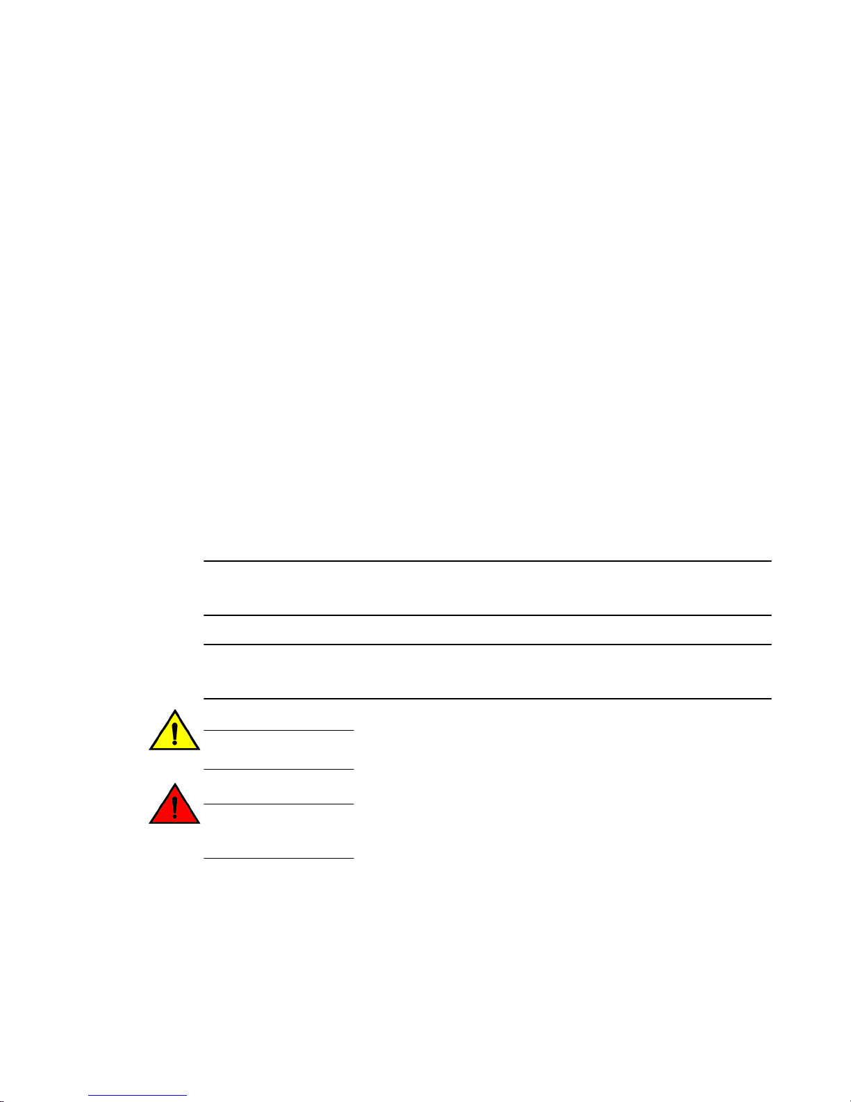
Traffic flow through firewall, NAT, and routing
The following figure shows how traffic flows through the firewall, NAT, and routing services within the
vRouter. Notice the order of firewall instances, destination Network Address Translation (DNAT),
routing decisions, and source Network Address Translation (SNAT).
16 Brocade 5600 vRouter Firewall Reference Guide
53-1003710-03
Page 17
Scenario 1: firewall instances applied to inbound traffic
FIGURE 1 Traffic flow through firewall, NAT, and routing components
Scenario 1: firewall instances applied to inbound traffic
In this scenario, firewall instances are applied to inbound (in) traffic on an interface. Notice that firewall
instances are evaluated before DNAT and routing decisions, and after SNAT.
Scenario 2: firewall instances applied to outbound traffic
In this scenario, firewall instances are applied to outbound (out ) traffic on an interface. Notice that
firewall is evaluated after DNAT and routing decisions, and after SNAT.
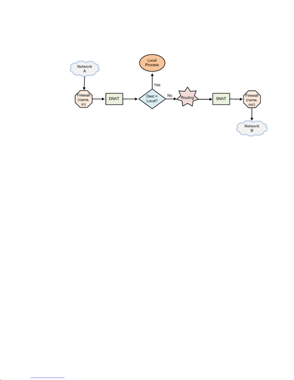
Zone-based firewall
Ordinary firewall rule sets are applied on a per-interface basis to act as a packet filter for the interface.
In a zone-based firewall, interfaces are grouped into security “zones,” where each interface in a zone
has the same security level.
Packet-filtering policies are applied to traffic flowing between zones. Traffic flowing between interfaces
that lie in the same zone is not filtered and flows freely because the interfaces share the same security
level.
The following figure shows an example of a zone-based firewall implementation. This example has
these characteristics:
• Three transit zones exist (that is, points where traffic transits the router): the private zone, the
demilitarized zone (DMZ), and the public zone.
• The dp0p1p4 interface lies in the public zone; the dp0p1p1 and dp0p1p2 interfaces lie in the private
zone; and the dp0p1p3 interface lies in the DMZ.
• The arrows from one zone to another zone represent traffic-filtering policies that are applied to traffic
flowing between zones.
• Traffic flowing between LAN 1 and LAN 2 remains within a single security zone. Thus, traffic from
LAN1 to LAN2, and conversely, flows unfiltered.
Brocade 5600 vRouter Firewall Reference Guide 17
53-1003710-03
Page 18
Firewall Overview
FIGURE 2 Zone-based firewall overview
By default, all traffic coming into the router and originating from the router is allowed.
Note the following additional points about zone-based firewalls:
• An interface can be associated with only one zone.
• An interface that belongs to a zone cannot have a per-interface firewall rule set applied to it, and
conversely.
• Traffic between interfaces that do not belong to any zone flows unfiltered, and per-interface firewall
rule sets can be applied to those interfaces.
• By default, all traffic to a zone is dropped unless explicitly allowed by a filtering policy for a source
zone (from_zone) .
• Filtering policies are unidirectional; they are defined as a “zone pair” that identifies the zone from
which traffic is sourced (from_zone ) and the zone to which traffic is destined (to_zone ). In the
preceding figure, these unidirectional policies can be seen as follows:
‐ From private to DMZ
‐ From public to DMZ
‐ From private to public
‐ From DMZ to public
‐ From public to private
‐ From DMZ to private
18 Brocade 5600 vRouter Firewall Reference Guide
53-1003710-03
Page 19
Configuration Examples
● Packet-filtering................................................................................................................ 19
● Stateful behavior............................................................................................................. 27
● Zone-based firewall.........................................................................................................28
● Using firewall with VRRP interfaces................................................................................32
● Viewing firewall information.............................................................................................34
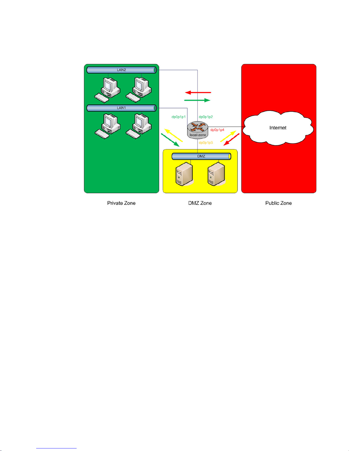
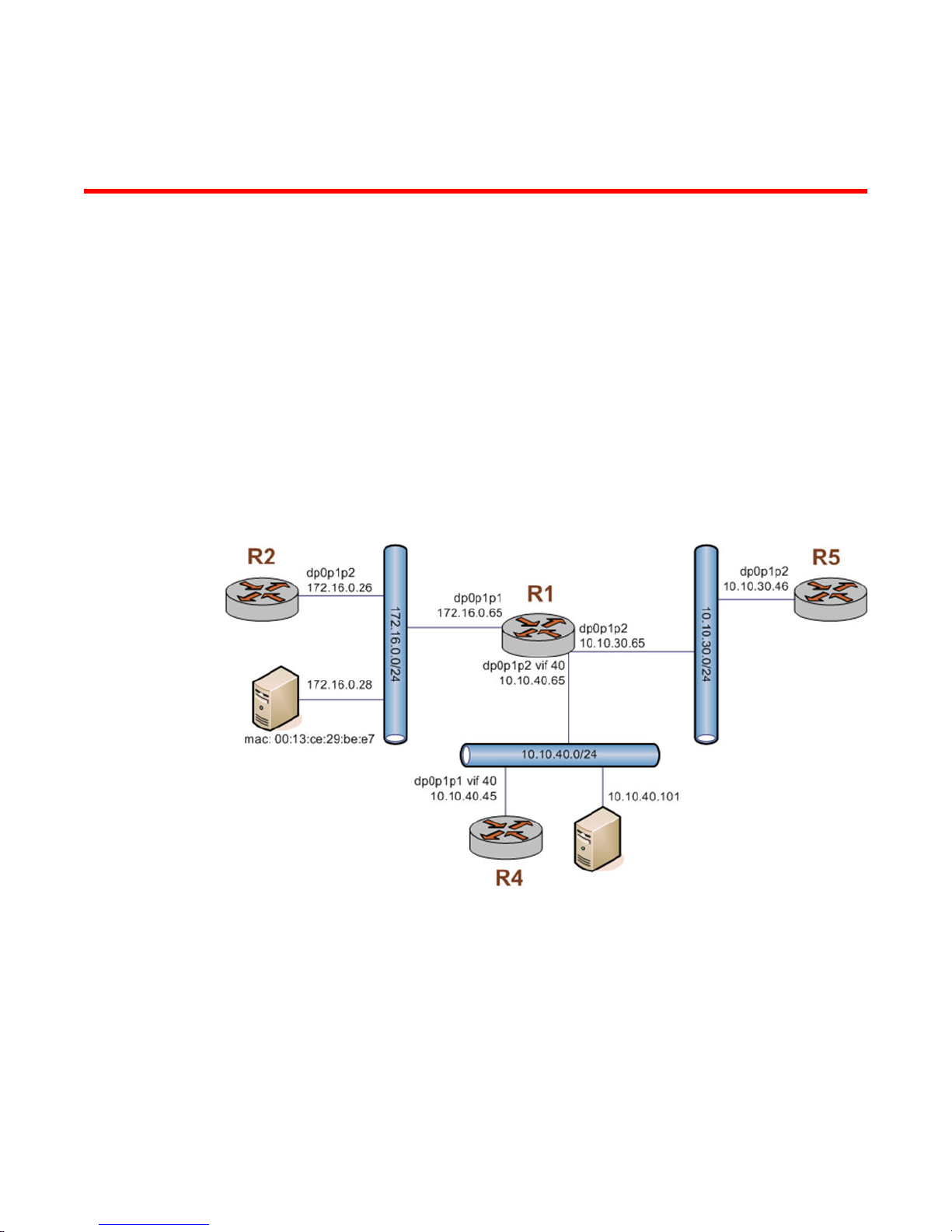
Packet-filtering
This section describes a sample configuration for firewall. When you have finished, the firewall is
configured on the R1 router, as shown in the following figure.
FIGURE 3 Firewall: sample configuration
This section includes the following examples:
• Filtering on source IP address on page 20
• Filtering on source and destination IP addresses on page 20
• Filtering on source IP address and destination protocol on page 21
• Defining a network-to-network filter on page 22
• Filtering on source MAC address on page 23
• Excluding an address on page 24
• Matching TCP flags on page 25
• Matching ICMP type names on page 25
Brocade 5600 vRouter Firewall Reference Guide
53-1003710-03
19
Page 20

Filtering on source IP address
• Matching groups on page 26
• Configuring stateful behavior per rule set on page 27
Filtering on source IP address
The following figure shows how to define a firewall instance that contains one rule, which filters
packets only on source IP address. This rule denies packets coming from the R2 router. It then applies
the firewall instance to packets inbound on the dp0p1p1 interface.
To create an instance that filters on source IP address, perform the following steps in configuration
mode.
Filtering on source IPTABLE 1
Step Command
Create the configuration node for the FWTEST-1 firewall
instance and its rule 1. This rule matches fragmented packets.
Define the action of this rule.
Define a rule that filters traffic on the 176.16.0.26 source IP
address.
Apply FWTEST-1 to inbound packets on dp0p1p1.
Commit the configuration.
Show the configuration.
Filtering on source and destination IP addresses
vyatta@R1# set security firewall name FWTEST-1 rule 1
fragment
vyatta@R1# set security firewall name FWTEST-1 rule 1
action accept
vyatta@R1# set security firewall name FWTEST-1 rule 1
source address 172.16.0.26
vyatta@R1# set interfaces dataplane dp0p1p1 firewall in
FWTEST-1
vyatta@R1# commit
vyatta@R1# show security firewall name FWTEST-1
rule 1 {
action accept
source {
address 172.16.0.26
}
}
vyatta@R1# show interfaces dataplane dp0p1p1
address 172.16.1.1/24
firewall FWTEST-1 {
in {
}
}
The following example shows how to define another firewall instance. This instance contains one rule,
which filters packets on both source and destination IP addresses. The rule accepts packets leaving
R5 through dp0p1p2 using 10.10.30.46 and destined for 10.10.40.101. It then applies the firewall
instance to packets outbound from the 1 virtual interface (vif 1) on the dp0p1p2 interface.
To create an instance that filters on source and destination IP addresses, perform the following steps
in configuration mode.
20 Brocade 5600 vRouter Firewall Reference Guide
53-1003710-03
Page 21

Filtering on source and destination IPTABLE 2
Step Command
Filtering on source IP address and destination protocol
Create the configuration node for the FWTEST-2 firewall
instance and its rule 1. This rule accepts traffic matching the
specified criteria.
Define a rule that filters traffic on the 10.10.30.46 source IP
address.
Define a rule that filters traffic on the 10.10.40.101 destination IP
address.
Apply FWTEST-2 to outbound packets on dp0p1p2 vif 40.
Commit the configuration.
Show the configuration.
vyatta@R1# set security firewall name FWTEST-2 rule 1
action accept
vyatta@R1# set security firewall name FWTEST-2 rule 1
source address 10.10.30.46
vyatta@R1# set security firewall name FWTEST-2 rule 1
destination address 10.10.40.101
vyatta@R1# set interfaces dataplane dp0p1p2 vif 40
firewall out FWTEST-2
vyatta@R1# commit
vyatta@R1# show security firewall name FWTEST-2
rule 1 {
action accept
destination {
address 10.10.40.101
}
source {
address 10.10.30.46
}
}
vyatta@R1# show interfaces dataplane dp0p1p2
vif 40 {
firewall {
out FWTEST-2
}
}
Filtering on source IP address and destination protocol
The following example shows how to define a firewall rule that filters on source IP address and
destination protocol. This rule allows TCP packets originating from address 10.10.30.46 (that is, R5),
and destined for the Telnet port of R1. The instance is applied to local packets (that is, packets destined
for this router, R1) through the dp0p1p2 interface.
To create a instance that filters on source IP address and destination protocol, perform the following
steps in configuration mode.
Filtering on source IP and destination protocolTABLE 3
Step Command
Create the configuration node for the FWTEST-3 firewall instance
and its rule 1. This rule accepts traffic matching the specified
criteria.
Define a rule that filters traffic on the 10.10.30.46 source IP
address.
Define a rule that filters TCP traffic.
Define a rule that filters traffic destined for the Telnet service.
vyatta@R1# set security firewall name FWTEST-3 rule 1
action accept
vyatta@R1# set security firewall name FWTEST-3 rule 1
source address 10.10.30.46
vyatta@R1# set security firewall name FWTEST-3 rule 1
protocol tcp
vyatta@R1# set security firewall name FWTEST-3 rule 1
destination port telnet
Brocade 5600 vRouter Firewall Reference Guide 21
53-1003710-03
Page 22

Defining a network-to-network filter
Filtering on source IP and destination protocol (Continued)TABLE 3
Step Command
Apply FWTEST-3 to packets bound for this router arriving on
dp0p1p2.
Commit the configuration.
Show the configuration.
Defining a network-to-network filter
The following example shows how to define a network-to-network packet filter, allowing packets
originating from 10.10.40.0/24 and destined for 172.16.0.0/24. It then applies the firewall instance to
packets inbound through the 40 virtual interface (vif 40) and the dp0p1p2 interface.
To create a network-to-network filter, perform the following steps in configuration mode.
vyatta@R1# set interfaces dataplane dp0p1p2 firewall
in FWTEST-3
vyatta@R1# commit
vyatta@R1# show security firewall name FWTEST-3
rule 1 {
action accept
destination {
port telnet
}
protocol tcp
source {
address 10.10.30.46
}
}
vyatta@R1# show interfaces dataplane dp0p1p2
firewall {
in FWTEST-3
}
Defining a network-to-network filterTABLE 4
Step Command
Create the configuration node for the FWTEST-4 firewall
instance and its rule 1. This rule accepts traffic matching the
specified criteria.
Define a rule that filters traffic coming from the 10.10.40.0/24
network.
Define a rule that filters traffic destined for the 172.16.0.0/24
network.
Apply FWTEST-4 to packets bound for this router arriving
through vif 40 on dp0p1p2.
Commit the configuration.
vyatta@R1# set security firewall name FWTEST-4 rule 1
action accept
vyatta@R1# set security firewall name FWTEST-4 rule 1
source address 10.10.40.0/24
vyatta@R1# set security firewall name FWTEST-4 rule 1
destination address 172.16.0.0/24
vyatta@R1# set interfaces dataplane dp0p1p2 vif 40
firewall in FWTEST-4
vyatta@R1# commit
22 Brocade 5600 vRouter Firewall Reference Guide
53-1003710-03
Page 23

Defining a network-to-network filter (Continued)TABLE 4
Step Command
Filtering on source MAC address
Show the configuration.
vyatta@R1# show security firewall name FWTEST-4
rule 1 {
action accept
destination {
address 172.16.0.0/24
}
source {
address 10.10.40.0/24
}
}
vyatta@R1# show interfaces dataplane dp0p1p2
vif 40 {
firewall {
in FWTEST-4
}
}
Filtering on source MAC address
The following example shows how to define a firewall instance that contains one rule, which filters
packets only on source medium access control (MAC) address. This rule allows packets coming from a
specific computer, identified by its MAC address rather than its IP address. The instance is applied to
packets inbound on the dp0p1p1 interface.
To create an instance that filters on source MAC address, perform the following steps in configuration
mode.
Filtering on source MAC addressTABLE 5
Step Command
Create the configuration node for the FWTEST-5 firewall
instance and its rule 1. This rule accepts traffic matching the
specified criteria.
Define a rule that filters traffic with the 00:13:ce:29:be:e7
source MAC address.
Apply FWTEST-5 to inbound packets on dp0p1p1.
Commit the configuration.
Show the configuration.
vyatta@R1# set security firewall name FWTEST-5 rule 1
action accept
vyatta@R1# set security firewall name FWTEST-5 rule 1
source mac-address 00:13:ce:29:be:e7
vyatta@R1# set interfaces dataplane dp0p1p1 firewall in
FWTEST-5
vyatta@R1# commit
vyatta@R1# show security firewall name FWTEST-5
rule 1 {
action accept
source {
mac-address 0:13:ce:29:be:e7
}
}
vyatta@R1# show interfaces dataplane dp0p1p1
address 172.16.1.1/24
firewall {
in FWTEST-5
}
Brocade 5600 vRouter Firewall Reference Guide 23
53-1003710-03
Page 24
Excluding an address
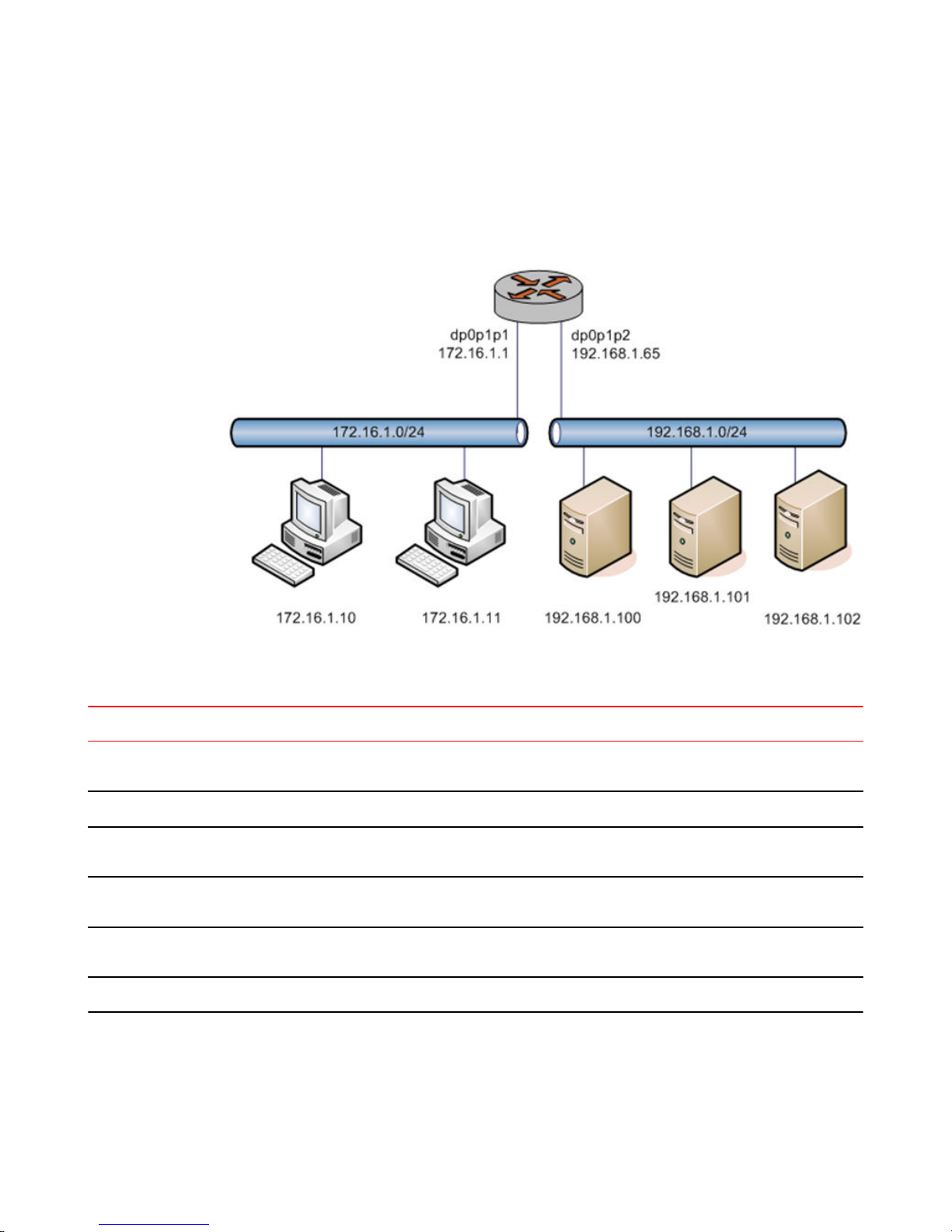
Excluding an address
The firewall rule shown in the following example allows all traffic from the 172.16.1.0/24 network
except traffic to the 192.168.1.100 server.
FIGURE 4 Excluding an address
To create an instance that excludes an address, perform the following steps in configuration mode.
Excluding an addressTABLE 6
Step Command
Create the configuration node for the FWTEST-5 firewall
instance and its rule 10. Give a description for the rule.
Allow all traffic that matches the rule to be accepted.
Allow any traffic from the 172.16.1.0/24 network that
matches the rule.
Allow traffic destined anywhere except the 192.168.1.100
destination address that matches the rule.
Apply the NEGATED-EXAMPLE instance to inbound
packets on dp0p1p1.
Commit the configuration.
vyatta@R1# set security firewall name NEGATED-EXAMPLE
rule 10 description "Allow all traffic from LAN except to
server 192.168.1.100"
vyatta@R1# set security firewall name NEGATED-EXAMPLE
rule 10 action accept
vyatta@R1# set security firewall name NEGATED-EXAMPLE
rule 10 source address 172.16.1.0/24
vyatta@R1# set security firewall name NEGATED-EXAMPLE
rule 10 destination address !192.168.1.100
vyatta@R1#
set interfaces dataplane dp0p1p1 firewall in NEGATEDEXAMPLE
vyatta@R1# commit
24 Brocade 5600 vRouter Firewall Reference Guide
53-1003710-03
Page 25

Excluding an address (Continued)TABLE 6
Step Command
Matching TCP flags
Show the configuration.
Accepting packets with specific TCP flags setTABLE 7
vyatta@R1# show security firewall
name NEGATED-EXAMPLE {
rule 10 {
action accept
description "Allow all traffic from LAN except to
server 192.168.1.100"
destination {
address !192.168.1.100
}
source {
address 172.16.1.0/24
}
}
}
vyatta@R1# show interfaces dataplane dp0p1p1
address 172.16.1.1/24
firewall {
in NEGATED-EXAMPLE
}
Matching TCP flags
The vRouter supports filtering on the TCP flags within TCP packets. For example, to create a rule to
accept packets with the SYN flag set and the ACK, FIN, and RST flags unset, perform the following
steps in configuration mode.
Step Command
Set the protocol to match to TCP.
Set the TCP flags to match.
Set the action to accept.
Commit the configuration.
Show the configuration.
vyatta@R1# set security firewall name TCP-FLAGS rule 30 protocol tcp
vyatta@R1# set security firewall name TCP-FLAGS rule 30 tcp flags SYN,!ACK,!
FIN,!RST
vyatta@R1# set security firewall name TCP-FLAGS rule 30 action accept
vyatta@R1# commit
vyatta@R1# show security firewall name TCP-FLAGS
rule 30 {
action accept
protocol tcp
tcp {
flags SYN,!ACK,!FIN,!RST
}
}
vyatta@R1#
Matching ICMP type names
Packets can be filtered for ICMP type names. For example, to create a rule that allows only ICMP echo
request packets, perform the following steps in configuration mode.
Brocade 5600 vRouter Firewall Reference Guide 25
53-1003710-03
Page 26

Matching groups
Accepting ICMP packets with specific type namesTABLE 8
Step Command
Set the protocol to match to ICMP.
Set the ICMP packet type to match.
Set the action to accept.
Commit the configuration.
Show the configuration.
Matching groups
Groups of addresses, ports, and networks can be defined for similar filtering. For example, to create a
rule that rejects traffic to a group of addresses and ports and from a group of networks, perform the
following steps in configuration mode.
Rejecting traffic based on groups of addresses, networks, and portsTABLE 9
vyatta@R1# set security firewall name ICMP-NAME rule 40 protocol icmp
vyatta@R1# set security firewall name ICMP-NAME rule 40 icmp type-name
echo-request
vyatta@R1# set security firewall name ICMP-NAME rule 40 action accept
vyatta@R1# commit
vyatta@R1# show security firewall name ICMP-NAME
rule 40 {
action accept
protocol icmp
icmp {
type-name echo-request
}
}
vyatta@R1#
Step Command
Add an address to an address group.
Add a network to a address group.
Add a port to a port group.
Add a port name to a port group.
Commit the configuration.
Show the configuration.
Specify a reject action within a firewall instance.
Specify an address group to match as a destination.
vyatta@R1# set resources group address-group SERVERS address
1.1.1.7
vyatta@R1# set resources group address-group SERVERS address
10.0.10.0/24
vyatta@R1# set resources group port-group PORTS port 22
vyatta@R1# set resources group port-group PORTS port http
vyatta@R1# commit
vyatta@R1# show resources
group {
address-group SERVERS {
address 10.0.10.0/24
address 1.1.1.7
}
port-group PORTS {
port 22
port http
}
}
vyatta@R1#
vyatta@R1# set security firewall name REJECT-GROUPS rule 10
action drop
vyatta@R1# set security firewall name REJECT-GROUPS rule 10
destination address SERVERS
26 Brocade 5600 vRouter Firewall Reference Guide
53-1003710-03
Page 27

Rejecting traffic based on groups of addresses, networks, and ports (Continued)TABLE 9
Step Command
Stateful behavior
Specify a port group to match as a destination.
Commit the configuration.
Show the configuration.
Stateful behavior
Stateless firewalls filter packets in isolation, based on static source and destination information. In
contrast, stateful firewalls track the state of network connections and traffic flows and allow or restrict
traffic based on whether its connection state is known and authorized. For example, when an initiation
flow is allowed in one direction, the responder flow is automatically and implicitly allowed in the return
direction.
By default, the vRouter firewall is stateless. If you want the firewall to operate statefully, you have two
choices:
• You can leave the firewall operating statelessly in general and specify stateful behavior per rule set
by configuring state rules within the rule set. This configuration is described in Configuring stateful
behavior per rule set on page 27.
• You can enable global stateful behavior by configuring global state policies. This configuration is
described in Configuring global state policies on page 28.
vyatta@R1# set security firewall name REJECT-GROUPS rule 10
destination port PORTS
vyatta@R1# commit
vyatta@R1# show security firewall name REJECT-GROUPS
rule 10{
action drop
destination {
address SERVERS
port PORTS
}
source {
address SERVERS
}
}
vyatta@R1#
Configuring stateful behavior per rule set
Even if you want the firewall to operate statelessly in general, you can still configure state rules within a
specific rule set.
The following example shows how to configure a rule in the TEST1 firewall rule set. Rule 1 accepts
stateful traffic flows and flows related to existing connections for all protocols.
To configure per-rule set state rules, perform the following steps in configuration mode.
Creating a per-rule set state ruleTABLE 10
Step Command
Create the configuration node for the TEST1 rule set
and give a description for the rule set.
Brocade 5600 vRouter Firewall Reference Guide 27
53-1003710-03
vyatta@R1# set security firewall name TEST1 description
"Filter traffic statefully"
Page 28

Configuring global state policies
Creating a per-rule set state rule (Continued)TABLE 10
Step Command
Create a state rule.
Commit the configuration.
Show the firewall configuration.
Configuring global state policies
You can change behavior to be globally stateful by setting a global state policy with security firewall
global-state-policy <protocol> on page 45. When state policies are defined, state rules for return
traffic of that type need not be explicitly mentioned within the rule sets.
The global state policy that is configured applies to all IPv4 and IPv6 traffic destined for, originating
from, or traversing the router. Note that after the firewall is configured to be globally stateful, this
setting overrides any state rules configured within the rule set.
The following example shows how to configure the firewall globally to allow all return traffic.
This behavior is the same as that configured in the TEST1 rule set in Configuring stateful behavior per
rule set on page 27, except that it is applied globally instead of being restricted to the one rule set.
To configure this global stateful behavior, perform the following steps in configuration mode.
vyatta@R1# set security firewall name TEST1 rule 1 action
accept
vyatta@R1# set security firewall name TEST1 rule 1 state
enable
vyatta@R1# commit
vyatta@R1# show security firewall name TEST1
description "Filter traffic statefully"
rule 1 {
action accept
state enable
}
Setting a global state policyTABLE 11
Step Command
Configure global state policy.
Commit the configuration.
Show the state policy configuration.
vyatta@R1# set security firewall global-state-policy icmp
vyatta@R1# set security firewall global-state-policy tcp
vyatta@R1# set security firewall global-state-policy udp
vyatta@R1# commit
vyatta@R1# show security firewall global-state-policy
icmp
tcp
udp
Zone-based firewall
The vRouter also supports a zone-based model. The following figure shows a zone-based
configuration with three user-defined zones.
The examples that follow show the configuration for this diagram.
28 Brocade 5600 vRouter Firewall Reference Guide
53-1003710-03
Page 29
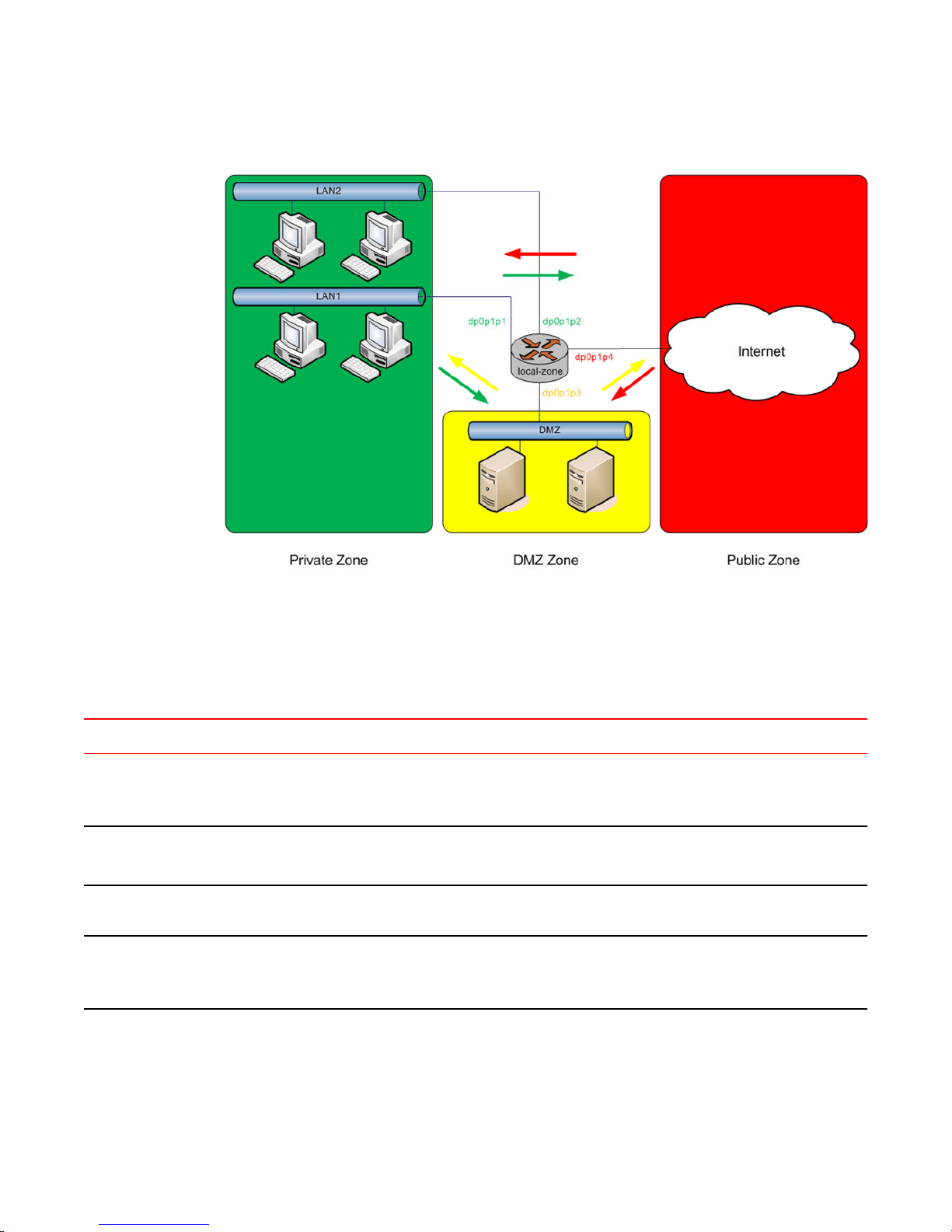
FIGURE 5 Zone-based firewall configuration
Filtering traffic between zones
Filtering traffic between zones
The following example shows how to filter traffic between zones by attaching rule sets to zone.
Creating the zone policiesTABLE 12
Step Command
Create a zone named private and attach
interfaces to it.
Create a zone named dmz and attach an
interface to it.
Create a zone named public and attach an
interface to it.
Create rule sets named to_private ,
to_dmz , and to_public .
vyatta@R1# set security zone-policy zone private description PRIVATE
vyatta@R1# set security zone-policy zone private interface dp0p1p1
vyatta@R1# set security zone-policy zone private interface dp0p1p2
vyatta@R1# set security zone-policy zone dmz description DMZ
vyatta@R1# set security zone-policy zone dmz interface dp0p1p3
vyatta@R1# set security zone-policy zone public description PUBLIC
vyatta@R1# set security zone-policy zone public interface dp0p1p4
vyatta@R1# set security firewall name to_private rule 1 action accept
vyatta@R1# set security firewall name to_dmz rule 1 action accept
vyatta@R1# set security firewall name to_public rule 1 action accept
Brocade 5600 vRouter Firewall Reference Guide 29
53-1003710-03
Page 30

Filtering traffic between the transit zones
Creating the zone policies (Continued)TABLE 12
Step Command
Attach the rule sets to each zone.
Commit the changes.
NOTE
Before committing changes to a zone, firewall requires that you should have an interface and a rule
set attached to the zone.
The following example shows how to view the configuration.
vyatta@R1# show security zone-policy
zone dmz {
description DMZ
interface dp0p1p3
to private {
firewall to_private
}
to public {
firewall to_public
}
}
zone private {
description PRIVATE
interface dp0p1p1
interface dp0p1p2
to dmz {
firewall to_dmz
}
to public {
firewall to_public
}
}
zone public {
description PUBLIC
interface dp0p1p4
to dmz{
firewall to_dmz
}
to private {
firewall to_private
}
}
vyatta@R1# set security zone-policy zone private to dmz firewall
to_dmz
vyatta@R1# set security zone-policy zone private to public firewall
to_public
vyatta@R1# set security zone-policy zone dmz to private firewall
to_private
vyatta@R1# set security zone-policy zone dmz to public firewall
to_public
vyatta@R1# set security zone-policy zone public to dmz firewall
to_dmz
vyatta@R1# set security zone-policy zone public to private firewall
to_private
vyatta@R1# commit
Filtering traffic between the transit zones
The first step in setting up zone-based traffic filtering is to create zone policies, as shown in the
following example. To create the zone policies, perform the following steps in configuration mode.
30 Brocade 5600 vRouter Firewall Reference Guide
53-1003710-03
Page 31

Creating the zone policiesTABLE 13
Step Command
Configuration Examples
Create the configuration node for the DMZ and give a description
for the zone.
Add the interface contained in the DMZ.
Create the configuration node for the private zone and give a
description for the zone.
Add one of the interfaces contained in the private zone.
Add the other interface contained in the private zone.
Create the configuration node for the public zone and give a
description for the zone.
Add the interface contained in the public zone.
Commit the configuration.
Show the configuration.
vyatta@R1# set security zone-policy zone dmz
description “DMZ ZONE”
vyatta@R1# set security zone-policy zone dmz
interface dp0p1p3
vyatta@R1# set security zone-policy zone private
description “PRIVATE ZONE”
vyatta@R1# set security zone-policy zone private
interface dp0p1p1
vyatta@R1# set security zone-policy zone private
interface dp0p1p2
vyatta@R1# set security zone-policy zone public
description “PUBLIC ZONE”
vyatta@R1# set security zone-policy zone public
interface dp0p1p4
vyatta@R1# commit
vyatta@R1# show security zone-policy
zone dmz {
description "DMZ ZONE"
interface dp0p1p3
}
zone private {
description "PRIVATE ZONE"
interface dp0p1p1
interface dp0p1p2
}
zone public {
description "PUBLIC ZONE"
interface dp0p1p4
}
At this point, while traffic can flow freely within a zone, no traffic flows between zones. All traffic flowing
from one zone to another is dropped. For example, because the dp0p1p1 and dp0p1p2 interfaces lie in
the same zone (private), traffic between these interfaces flows freely. However, traffic from dp0p1p2 to
dp0p1p3 (which lies in the DMZ) is dropped.
The next step, shown in the following example, is to create firewall rule sets to allow traffic between
zones. The first rule set allows all traffic to the public zone. To configure this rule set, perform the
following steps in configuration mode.
Creating the rule set for traffic to the public zoneTABLE 14
Step Command
Create the configuration node for the to_public rule set
and give a description for the rule set.
Create a rule to accept all traffic sent to the public
zone.
Commit the configuration.
Brocade 5600 vRouter Firewall Reference Guide 31
53-1003710-03
vyatta@R1# set security firewall name
to_public description "allow all traffic
to PUBLIC zone"
vyatta@R1# set security firewall name
to_public rule 1 action accept
vyatta@R1# commit
Page 32

Using firewall with VRRP interfaces
Step Command
Creating the rule set for traffic to the public zone (Continued)TABLE 14
Show the firewall configuration.
Using firewall with VRRP interfaces
A Virtual Router Redundancy Protocol (VRRP) interface is a logical abstraction that allows the system
to implement RFC 3768-compliant MAC address behavior. VRRP can be configured with or without
VRRP interfaces. To achieve the expected results when filtering traffic, it is important to understand
how traffic flows on systems that use VRRP.
• If no VRRP interface is designed, traffic flows in and out through a physical interface or virtual
interface.
• If a VRRP interface is designed, traffic flows in through the VRRP interface and out through the
physical interface or virtual interface.
This traffic flow affects how you design and attach firewall rule sets.
Applying a rule set to a VRRP interface
vyatta@R1# show security firewall name
to_public
description "allow all traffic to PUBLIC
zone"
rule 1 {
action accept
}
When a host sends a packet to the router, the packet ingresses through the VRRP interface. But when
the router sends traffic to the host, traffic egresses through the parent interface or virtual interface.
The firewall rule sets for the VRRP interface and the physical interface are independent. Specifically,
packet-filtering rules applied to incoming traffic on the parent interface are not applied to traffic arriving
on the VRRP interface. When designing firewall rule sets for incoming traffic, make sure you apply an
appropriate rule set for your VRRP interface; otherwise, all incoming traffic is unfiltered.
The example in Filtering on source IP address on page 20 shows how to define a simple firewall rule
set, FWTEST-1, which filters on source IP address. The following example shows how to apply the
same rule set to inbound traffic on the VRRP interface. In this example, the dp0p1p3 interface is
already configured. Specifically:
• It is a member of VRRP group 15.
• It has rule set FWTEST-1 applied for inbound traffic.
To apply the rule set to the VRRP interface, perform the following steps in configuration mode.
32 Brocade 5600 vRouter Firewall Reference Guide
53-1003710-03
Page 33

Applying a firewall rule set to a VRRP interfaceTABLE 15
Step Command
Using VRRP with a zone-based firewall
View the initial configuration for the
interfaces.
Attach the same FW-TEST1 rule set for
inbound traffic on the VRRP interface.
Commit the configuration.
vyatta@R1# show interfaces
dataplane dp0p160p1 {
address 10.1.32.73/24
mtu 1500
}
dataplane dp0p192p1 {
address 10.10.10.3/24
address 2014:14::3/64
mtu 1500
vrrp {
vrrp-group 10 {
virtual-address 10.10.10.50
}
}
}
dataplane dp0p224p1 {
address 192.168.1.1/24
ip {
}
mtu 1500
}
dataplane dp0p256p1 {
address 20.20.20.3/24
address 2020:20::3/64
mtu 1500
}
loopback lo {
ipv6 {
}
}
vyatta@R1# set interfaces dataplane dp0p192p1 firewall in NEGATEDEXAMPLE
vyatta@R1# commit
Show the configuration.
vyatta@R1# show interfaces dataplane dp0p192p1
address 172.16.1.20/24
firewall {
in FWTEST-1
}
mtu 1500
vrrp {
vrrp-group 15 {
advertise-interval 1
preempt true
sync-group test
virtual-address 172.16.1.25
}
}
Using VRRP with a zone-based firewall
When a physical interface or virtual interface has a VRRP interface defined, all incoming traffic arrives
through the VRRP interface. Zone-based firewalls drop all traffic in and out unless explicitly allowed.
Therefore, if you are using VRRP interfaces with a zone-based firewall, you must make sure you
include the VRRP interfaces in your zone.
To use VRRP interface in a zone you must attach the physical interface on which VRRP is enabled. The
configuration is the same as zone configuration on a physical interface, the only difference is that VRRP
is running on this interface.
Brocade 5600 vRouter Firewall Reference Guide 33
53-1003710-03
Page 34

Viewing firewall information
Viewing firewall information
This section describes how to display firewall configuration information.
Showing firewall instance information
You can see how firewall instances are set up by using security firewall on page 39 in operational
mode and specifying the name of the instance. If no instance is specified, then all defined instances
are displayed.
The following example shows how to display configuration information for firewall instances.
vyatta@R1:~$ show security firewall
---------------------------------------
Rulesets Information: Firewall
---------------------------------------
--------------------------------------------------------------------------------
Firewall "fw_1":
Active on (dp0p192p1, in)
rule action proto packets bytes
---- ------ ----- ------- -----
1 allow tcp 0 0
condition - stateful proto tcp flags S/FSRA all
8 allow any 0 0
condition - stateful to { 20.20.20.0/24 }
---------------------------------------
Rulesets Information: Firewall
---------------------------------------
--------------------------------------------------------------------------------
Firewall "default_state_group":
Active on (dp0p192p1)
rule action proto packets bytes
---- ------ ----- ------- -----
100 allow tcp 0 0
condition - stateful proto tcp all
200 allow udp 0 0
condition - stateful proto udp all
300 allow icmp 0 0
condition - stateful proto icmp all
Showing firewall configuration on interfaces
The following example shows how to apply the FWTEST-1 firewall instance to the dp0p1p1 interface.
vyatta@R1# set interfaces dataplane dp0p1p1 firewall in FWTEST-1
Showing firewall configuration
You can view firewall information in configuration nodes by using the show command in configuration
mode. The following example shows how to display firewall configuration in configuration mode with
security firewall on page 39.
vyatta@R1# show security firewall
name FWTEST-1 {
rule 1 {
34 Brocade 5600 vRouter Firewall Reference Guide
53-1003710-03
Page 35

action accept
source {
address 172.16.0.26
}
}
}
name FWTEST-2 {
rule 1 {
action accept
destination {
address 10.10.40.101
}
source {
address 10.10.30.46
}
}
}
name FWTEST-3 {
rule 1 {
action accept
destination {
port telnet
}
protocol tcp
source {
address 10.10.30.46
}
}
}
name FWTEST-4 {
rule 1 {
action accept
destination {
address 172.16.0.0/24
}
source {
address 10.10.40.0/24
}
}
}
vyatta@R1#
Configuration Examples
Brocade 5600 vRouter Firewall Reference Guide 35
53-1003710-03
Page 36

Showing firewall configuration
36 Brocade 5600 vRouter Firewall Reference Guide
53-1003710-03
Page 37

Global Firewall Commands
● clear firewall.................................................................................................................... 38
● security firewall................................................................................................................39
● show security firewall <interface>................................................................................... 40
Brocade 5600 vRouter Firewall Reference Guide 37
53-1003710-03
Page 38

clear firewall
clear firewall
Clears the counters associated with a firewall rule set.
Syntax
Command Default
Modes
Usage Guidelines
clear firewall
When no rule is specified, the counters are cleared for all rules in the rule set.
Operational mode
Use this command to clear the counters associated with a firewall rule set or a rule within a firewall rule
set.
38 Brocade 5600 vRouter Firewall Reference Guide
53-1003710-03
Page 39

security firewall
Enables or disables firewall on the vRouter.
security firewall
Syntax
Modes
Configuration
Statement
Usage Guidelines
set security firewall
delete security firewall
show security firewall
Configuration mode
security {
firewall {
}
}
Use this command to define firewall configuration settings and rule sets, using other firewall
commands. After a firewall rule set has been defined, it must be applied to an interface as a packet filter
by using firewall-related interface commands. Until a firewall rule set has been applied to an interface,
it has no effect on traffic destined for or traversing the system.
Note that after the final user-defined rule in a rule set is issued, an implicit rule of “reject all” takes
effect.
Use the set form of this command to create a firewall configuration.
Use the delete form of this command to delete a firewall configuration.
Use the show form of this command to display a firewall configuration.
Brocade 5600 vRouter Firewall Reference Guide 39
53-1003710-03
Page 40

show security firewall <interface>
show security firewall <interface>
Displays statistics for a firewall rule set of an interface.
Syntax
Command Default
Parameters
Modes
Usage Guidelines
Examples
show security firewall interface
When used with no option, the command shows information for all configured firewall rule sets.
interface
A type of interface. For detailed keywords and arguments, refer to the table in
the “Usage Guidelines” section that follows.
Operational mode
Use this command to display statistics about configured firewall rule sets.
The following example shows how to display statistics for firewall rule sets. The output includes
statistics for the configured global state and configured firewall rule sets.
vyatta@R1# show security firewall
---------------------------------------
Rulesets Information: Firewall
---------------------------------------
--------------------------------------------------------------------------------
Firewall "fw_1":
Active on (dp0p192p1, in)
rule action proto packets bytes
---- ------ ----- ------- -----
1 allow tcp 0 0
condition - stateful proto tcp flags S/FSRA all
8 allow any 0 0
condition - stateful to { 20.20.20.0/24 }
---------------------------------------
Rulesets Information: Firewall
---------------------------------------
--------------------------------------------------------------------------------
Firewall "default_state_group":
Active on (dp0p192p1)
rule action proto packets bytes
---- ------ ----- ------- -----
100 allow tcp 0 0
condition - stateful proto tcp all
200 allow udp 0 0
condition - stateful proto udp all
300 allow icmp 0 0
condition - stateful proto icmp all
40 Brocade 5600 vRouter Firewall Reference Guide
53-1003710-03
Page 41

Firewall Commands
● security firewall all-ping <state>...................................................................................... 42
● security firewall broadcast-ping <state>..........................................................................43
● security firewall config-trap <state>.................................................................................44
● security firewall global-state-policy <protocol>................................................................45
● security firewall name <name>....................................................................................... 46
● security firewall name <name> default-action <action>.................................................. 47
● security firewall name <name> default-log <action>.......................................................48
● security firewall name <name> description <description>.............................................. 49
● security firewall name <name> rule <rule-number>........................................................50
● security firewall name <name> rule <rule-number> action <action>.............................. 51
● security firewall name <name> rule <rule-number> description <description>...............52
● security firewall name <name> rule <rule-number> destination <destination>...............53
● security firewall name <name> rule <rule-number> disable........................................... 55
● security firewall name <name> rule <rule-number> dscp <value>................................. 56
● security firewall name <name> rule <rule-number> ethertype <type>............................57
● security firewall name <name> rule <rule-number> fragment.........................................58
● security firewall name <name> rule <rule-number> icmp............................................... 59
● security firewall name <name> rule <rule-number> icmpv6........................................... 60
● security firewall name <name> rule <rule-number> ipv6-route type <number>..............61
● security firewall name <name> rule <rule-number> log.................................................. 62
● security firewall name <name> rule <rule-number> mark <action>................................ 63
● security firewall name <name> rule <rule-number> pcp <number>................................64
● security firewall name <name> rule <rule-number> police <limiting-method>................65
● security firewall name <name> rule <rule-number> protocol.......................................... 67
● security firewall name <name> rule <rule-number> source <source>............................ 68
● security firewall name <name> rule <rule-number> state <state>.................................. 70
● security firewall name <name> rule <rule-number> tcp flags <flags>.............................71
● security firewall session-log <protocol>.......................................................................... 72
● security firewall tcp-strict................................................................................................. 74
● interfaces <interface> firewall <state>............................................................................ 75
● Related commands......................................................................................................... 76
Brocade 5600 vRouter Firewall Reference Guide
53-1003710-03
41
Page 42

security firewall all-ping <state>
security firewall all-ping <state>
Enables or disables responses to all ICMP echo request (ping) messages.
Syntax
Command Default
Parameters
Modes
Configuration
Statement
Usage Guidelines
set security firewall all-ping { disable | enable }
delete security firewall all-ping [ disable | enable ]
show security firewall all-ping
Responses to ICMP echo request messages are enabled.
disable
Disables responses to ICMP echo request messages.
enable
Enables responses to ICMP echo request messages.
Configuration mode
security {
firewall {
all-ping
disable
enable
}
}
Use this command to specify whether the system responds to ICMP echo request messages (pings).
These messages include all ping messages: unicast, broadcast, or multicast.
Pings are a network tool that help establish the reachability of a device from the local system. Pings are
often disallowed because they are a potential means of denial of service (DoS) attacks.
Use the set form of this command to enable or disable responses to pings.
Use the delete form of this command to restore the default behavior of responding to pings.
Use the show form of this command to display the state of responding to pings.
42 Brocade 5600 vRouter Firewall Reference Guide
53-1003710-03
Page 43

security firewall broadcast-ping <state>
Enables or disables response to broadcast ICMP echo request and time-stamp request messages.
security firewall broadcast-ping <state>
Syntax
Command Default
Parameters
Modes
Configuration
Statement
Usage Guidelines
set security firewall broadcast-ping { disable | enable }
delete security firewall broadcast-ping [ disable | enable ]
show security firewall broadcast-ping
ICMP echo and time-stamp request messages do not receive responses.
disable
Disables responses to broadcast ICMP echo and time-stamp request
messages.
enable
Enables responses to broadcast ICMP echo and time-stamp request
messages.
Configuration mode
security {
firewall {
broadcast-ping
disable
enable
}
}
Use this command to specify whether the system responds to broadcast ICMP echo request and
broadcast ICMP time-stamp request messages.
Pings are a network tool that help establish the reachability of a device from the local system. Pings,
particularly broadcast pings, are often disallowed because they are a potential means for denial of
service (DoS) attacks. time-stamp requests are used to query another device for the current date and
time. Time-stamp requests are also often disallowed both because they are a potential means for a DoS
attack and because the query allows an attacker to learn the date set on the queried machine.
Use the set form of this command to specify whether the system responds to broadcast ICMP ICMP
echo and time-stamp request messages.
Use the delete form of this command to restore the default behavior of not responding to broadcast
ICMP ICMP echo and time-stamp request messages.
Use the show form of this command to display the behavior to broadcast ICMP ICMP echo and timestamp request messages.
Brocade 5600 vRouter Firewall Reference Guide 43
53-1003710-03
Page 44

security firewall config-trap <state>
security firewall config-trap <state>
Enables the generation of Simple Network Message Protocol (SNMP) traps regarding firewall
configuration changes.
Syntax
Command Default
Parameters
Modes
Configuration
Statement
Usage Guidelines
set security firewall config-trap { disable | enable }
delete security firewall config-trap [ disable | enable ]
show security firewall config-trap
Disabled.
disable
Disables the generation of SNMP traps regarding a firewall configuration
change.
enable
Enables the generation of SNMP traps regarding a firewall configuration
change.
Configuration mode
security {
firewall {
config-trap
disable
enable
}
}
A device uses SNMP traps to notify, without solicitation, the manager of the device about significant
events, such as firewall configuration changes.
Use the set form of this command to enable the generation of SNMP traps when a firewall configuration
change is made.
Use the delete form of this command to restore the default behavior.
Use the show form of this command to display the state regarding the generation of SNMP traps on
firewall configuration changes.
44 Brocade 5600 vRouter Firewall Reference Guide
53-1003710-03
Page 45

security firewall global-state-policy <protocol>
security firewall global-state-policy <protocol>
Configures the global state parameters for firewall.
Syntax
Command Default
Parameters
Modes
Configuration
Statement
set security firewall global-state-policy { icmp | tcp | udp }
delete security firewall global-state-policy [ icmp | tcp | udp ]
show security firewall global-state-policy
If this statement is not configured, the firewall is stateless. In this case, specific rules governing
statefulness can be configured within the rule set.
icmp
Enable ICMP state monitoring for firewall.
tcp
Enable TCP state monitoring for firewall.
udp
Enable UDP state monitoring for firewall.
Configuration mode
security {
firewall {
global-state-policy {
icmp
tcp
udp
}
}
}
Usage Guidelines
Setting this configuration node makes the firewall globally stateful. You then define policies for
established traffic, related traffic, and invalid traffic.
When configured to be stateful, the firewall tracks the state of network connections and traffic flows and
allows or restricts traffic based on whether its connection state is known and authorized. For example,
when an initiation flow is allowed in one direction, the stateful firewall automatically allows responder
flows in the return direction.
The statefulness policy that is configured applies to all IPv4 and IPv6 traffic destined for, originating
from, or traversing the router. After the firewall is configured to be globally stateful, this setting overrides
any state rules configured within rule sets.
Use the set form of this command to configure a global statefulness policy for firewall.
Use the delete form of this command to delete a global statefulness policy for firewall.
Use the show form of this command to display a global statefulness policy for firewall.
Brocade 5600 vRouter Firewall Reference Guide 45
53-1003710-03
Page 46

security firewall name <name>
security firewall name <name>
Creates and names a firewall rule.
Syntax
Parameters
Modes
Configuration
Statement
Usage Guidelines
set security firewall name name
delete security firewall name [ name ]
show security firewall name
name
Multi-node. The name of a firewall rule set. The name must not contain a space
or any other of the following special characters: |, ;, &, $, <, or >. The name can
be as many as 28 characters long.
You can define more than one firewall rule set by creating more than one name
configuration node.
Configuration mode
security {
firewall {
name name
}
}
Use this command to create and name a firewall rule set. A firewall rule set is a named collection of as
many as 9,999 packet-filtering rules. Following the configurable rules is an implicit rule, rule 10000,
which denies all traffic.
Use the set form of this command to create and name a firewall rule set.
Use the delete form of this command to delete to a firewall rule set.
Use the show form of this command to display a firewall rule set.
46 Brocade 5600 vRouter Firewall Reference Guide
53-1003710-03
Page 47

security firewall name <name> default-action <action>
security firewall name <name> default-action <action>
Defines the default action for a firewall rule.
Syntax
Parameters
Modes
Configuration
Statement
set security firewall name name default-action { accept | drop }
delete security firewall name name default-action [ accept | drop ]
show security firewall name name default-action
name
Multi-node. The name of a firewall rule set. The name must not contain a space
or any other of the following special characters: |, ;, &, $, <, or >. The name can
be as many as 28 characters long.
You can define more than one firewall rule set by creating more than one name
configuration node.
accept
Accepts the default action for the specified rule set.
drop
Denies the default action for the specified rule set.
Configuration mode
security {
firewall {
name name {
default-action
accept
drop
}
}
}
Usage Guidelines
A firewall rule set is a named collection of as many as 9,999 packet-filtering rules. Following the
configurable rules is an implicit rule, rule 10000, which denies all traffic.
NOTE
The “deny all” rule stays in effect until every reference to the rule set is removed; that is, until every
packet filter that references the rule set has been removed from all interfaces.
Use the set form of this command to define an IP firewall rule.
Use the delete form of this command to delete a firewall rule.
Use the show form of this command to display a firewall rule.
Brocade 5600 vRouter Firewall Reference Guide 47
53-1003710-03
Page 48

security firewall name <name> default-log <action>
security firewall name <name> default-log <action>
Defines an IP firewall rule set to log packets that reach the default action.
Syntax
Parameters
Modes
Configuration
Statement
set security firewall name name default-log { accept | drop }
delete security firewall name name default-log [ accept | drop ]
show security firewall name name default-log
name
Multi-node. The name of a firewall rule set. The name must not contain a space
or any other of the following special characters: |, ;, &, $, <, or >. The name can
be as many as 28 characters long.
You can define more than one firewall rule set by creating more than one name
configuration node.
accept
Accept packet if no pior rules are matched.
drop
Drop packet if no prior rules are matched.
Configuration mode
security {
firewall {
name name {
default-log
action
drop
}
}
}
Usage Guidelines
Use this command to define an IP firewall rule set.
A firewall rule set is a named collection of as many as 9999 packet-filtering rules. Following the
configurable rules is an implicit rule, rule 10000, which denies all traffic.
NOTE
The “deny all” rule stays in effect until every reference to the rule set is removed; that is, until every
packet filter that references the rule set has been removed from all interfaces.
Use the set form of this command to define a firewall rule set.
Use the delete form of this command to delete a firewall rule set.
Use the show form of this command to display a firewall rule set.
48 Brocade 5600 vRouter Firewall Reference Guide
53-1003710-03
Page 49

security firewall name <name> description <description>
security firewall name <name> description <description>
Provides a brief description for an IP firewall group.
Syntax
Parameters
Modes
Configuration
Statement
Usage Guidelines
set security firewall name name description description
delete security firewall name name
show security firewall name name
name
The name of a firewall group.
description
A brief description of the rule. If the description contains spaces, it must be
enclosed in double quotation marks.
Configuration mode
security {
firewall {
name name {
description description
}
}
}
Providing a description for an firewall group can help you to quickly determine the purpose of the rule
when viewing the configuration.
Use the set form of this command to provide brief description of a firewall group.
Use the delete form of this command to delete a description.
Use the show form of this command to display a description.
Brocade 5600 vRouter Firewall Reference Guide 49
53-1003710-03
Page 50

security firewall name <name> rule <rule-number>
security firewall name <name> rule <rule-number>
Defines a rule for a firewall rule set.
Syntax
Parameters
Modes
Configuration
Statement
Usage Guidelines
set security firewall name name rule rule-number
delete security firewall name name rule rule-number
show security firewall name name rule
name
The name of a firewall rule set.
rule-number
The numeric identifier of a rule. The identifier ranges from 1 through 9999.
Configuration mode
security {
firewall {
name name {
rule rule-number
}
}
}
Use this command to define a rule within a firewall rule set.
A firewall rule set consists as many as 9,999 configurable rules. Following the last configured rule, a
system rule (rule 10000) with an action of “deny all” is applied.
To avoid having to renumber firewall rules, a good practice is to number rules in increments of 10. This
increment allows room for the insertion of new rules within the rule set.
Use the set form of this command to define a firewall rule within a firewall rule set.
Use the delete form of this command to delete a rule from a firewall rule set.
Use the show form of this command to display a rule from a firewall rule set.
50 Brocade 5600 vRouter Firewall Reference Guide
53-1003710-03
Page 51

security firewall name <name> rule <rule-number> action <action>
security firewall name <name> rule <rule-number> action <action>
Defines the actions for a firewall rule set.
Syntax
Parameters
Modes
set security firewall name name rule rule-number action { accept | drop }
delete security firewall name name rule rule-number action
show security firewall name name rule rule-number action
name
The name of a firewall rule set.
rule-number
The numeric identifier of a rule. The identifier ranges from 1 through 9999.
accept
Accepts the packet. To be performed when a packet satisfies the match criteria
specified in the rule.
Exactly one action must be specified. The system does not enforce this oneaction limit at commit time, but the configuration does not function unless only
one action is specified.
drop
Drops the packet silently. To be performed when a packet satisfies the match
criteria specified in the rule.
Exactly one action must be specified. The system does not enforce this oneaction limit at commit time, but the configuration does not function unless only
one action is specified.
Configuration mode
Configuration
Statement
Usage Guidelines
security {
firewall {
name name {
rule rule-number
action
{
accept
drop
}
}
}
}
Use the set form of this command to define a firewall rule within a firewall rule set.
Use the delete form of this command to delete a rule from a firewall rule set.
Use the show form of this command to display a rule from a firewall rule set.
Brocade 5600 vRouter Firewall Reference Guide 51
53-1003710-03
Page 52

security firewall name <name> rule <rule-number> description <description>
security firewall name <name> rule <rule-number> description
<description>
Provides a brief description for an IP firewall rule.
Syntax
Parameters
Modes
Configuration
Statement
Usage Guidelines
set security firewall name name rule rule-number description description
delete security firewall name name rule rule-number description
show security firewall name name rule rule-number description
name
The name of a firewall rule set.
rule-number
The numeric identifier of a rule. The identifier ranges from 1 through 9999.
description
A brief description of the rule. If the description contains spaces, it must be
enclosed in double quotation marks.
Configuration mode
security {
firewall {
name name {
rule rule-number {
description description
}
}
}
}
Providing a description for a firewall rule can help you to quickly determine the purpose of the rule when
viewing the configuration.
Use the set form of this command to provide brief description of a firewall rule.
Use the delete form of this command to delete the description of a firewall rule.
Use the show form of this command to display the description of a firewall rule.
52 Brocade 5600 vRouter Firewall Reference Guide
53-1003710-03
Page 53

security firewall name <name> rule <rule-number> destination <destination>
security firewall name <name> rule <rule-number> destination
<destination>
Defines the destination address, MAC address, or destination port for a firewall rule set.
Syntax
Parameters
set security firewall name name rule rule-number destination { address address | mac-address
address | port port }
delete security firewall name name rule rule-number destination [ address | mac-address | port ]
show security firewall name name rule rule-number destination
name
The name of a firewall rule set.
rule-number
The numeric identifier of a rule. The identifier ranges from 1 through 9999.
address address
Specifies a destination address to match. Address formats are as follows:
ip-address: An IPv4 address.
ip-address/prefix: A network address, where 0.0.0.0/0 matches any network.
!ip-address: All IP addresses except the one specified.
!ip-address/prefix: All network addresses except the one specified.
ipv6-address: An IPv6 address; for example, fe80::20c:29fe:fe47:f89.
ip-address/prefix: A network address, where ::/0 matches any network; for
example, fe80::20c:29fe:fe47:f88/64.
!ipv6-address: All IP addresses except the one specified.
!ip-address/prefix: All network addresses except the one specified.
When both an address and a port are specified, the packet is considered a
match only if both the address and the port match.
mac-address address
Matches the media access control (MAC) address in the source address. The
address format is six 8-bit numbers, separated by colons, in hexadecimal; for
example, 00:0a:59:9a:f2:ba.
port port
Specifies a destination port to match; this criterion applies only when the
protocol is TCP or UDP. Port formats are as follows:
port-name : The name of an IP service; for example, http. You can specify any
service name in the /etc/services file.
port-number : A port number. The number ranges from 1 through 65535.
start-end: A range of ports; for example, 1001-1005.
You can use a combination of these formats, separated by commas, in a list.
You can also negate the entire list by prefixing it with the negation operator
(exclamation mark [!]); for example, .
When both an address and a port are specified, the packet is considered a
match only if both the address and the port match.
Brocade 5600 vRouter Firewall Reference Guide 53
53-1003710-03
Page 54

Firewall Commands
Modes
Configuration
Statement
Usage Guidelines
Configuration mode
security {
firewall {
name name {
rule rule-number
destination {
address address
mac-address address
port port
}
}
}
}
Use the set form of this command to define a destination address, MAC address, or destination port
within a firewall rule set.
Use the delete form of this command to delete a destination address, MAC address, or destination port
from a firewall rule set.
Use the show form of this command to display a destination address, MAC address, or destination port
from a firewall rule set.
54 Brocade 5600 vRouter Firewall Reference Guide
53-1003710-03
Page 55

security firewall name <name> rule <rule-number> disable
security firewall name <name> rule <rule-number> disable
Disables the specified IP firewall rule.
Syntax
Command Default
Parameters
Modes
Configuration
Statement
Usage Guidelines
set security firewall name name rule rule-number disable
delete security firewall name name rule rule-number disable
show security firewall name name rule rule-number
The rule is enabled.
name
The name of a firewall rule set.
rule-number
The numeric identifier of a rule. The identifier ranges from 1 through 9999.
Configuration mode
security {
firewall {
name name {
rule rule-number {
disable
}
}
}
}
Use this command to disable an IP firewall rule. Disabling a firewall rule is a useful way to test how the
firewall performs minus a specific rule without having to delete and then re-enter the rule.
Use the set form of this command to disable a firewall rule
Use the delete form of this command to delete a firewall rule.
Use the show form of this command to display a firewall rule.
Brocade 5600 vRouter Firewall Reference Guide 55
53-1003710-03
Page 56

security firewall name <name> rule <rule-number> dscp <value>
security firewall name <name> rule <rule-number> dscp <value>
Specifies the Differentiated Services Code Point (DSCP) value for a firewall rule set.
Syntax
Parameters
set security firewall name name rule rule-number dscp value
delete security firewall name name rule rule-number dscp
show security firewall name name rule rule-number dscp
dscp value
Specifies the DSCP value to match in the incoming IP header. For the value,
enter one of the following:
number: A DSCP number ranges from 0 through 63. DSCP matches packets
with headers that include this DSCP value. If this option is not set, the DSCP
field retains its original value.
classifier: The traffic classifier for the per-hop behavior defined by the DS field
in the IP header.
• default: The Default Class (00000) for best-effort traffic.
• afnumber: The Assured Forwarding Class for assurance of delivery as
defined in RFC 2597. Depending on the forwarding class and the drop
precedence, the class can be one of the following values: af11 through af13,
af21 through af23, af31 through af33, or af41 through af43.
• csnumber: Class Selector for network devices that use the Precedence field
in the IPv4 header. The number ranges from 1 to 7 and indicates the
precedence, for example cs1.
• ef: Expedited Forwarding, per-hop behavior.
• va: Voice Admit, Capacity-Admitted Traffic.
Modes
Configuration
Statement
Usage Guidelines
Configuration mode
security {
firewall {
name name {
rule rule-number {
dscp value
}
}
}
}
Use the set form of this command to define the DSCP value to match.
Use the delete form of this command to delete the DSCP value.
Use the show form of this command to display the DSCP value for a firewall rule set.
56 Brocade 5600 vRouter Firewall Reference Guide
53-1003710-03
Page 57

security firewall name <name> rule <rule-number> ethertype <type>
security firewall name <name> rule <rule-number> ethertype <type>
Specifies the Ethernet type for a firewall rule set.
Syntax
Command Default
Parameters
Modes
Configuration
Statement
Usage Guidelines
set security firewall name name rule rule-number ethertype type
delete security firewall name name rule rule-number ethertype
show security firewall name name rule rule-number ethertype
By default, the network firewall allows the transmission of known Ethernet-type packets in the network.
ethertype type
Specifies matching for the Ethernet type.
type: The Ethernet type; for example, IPv4. You can specify any Ethernet name
listed in the /etc/ethertypes file. You can also enter the hexadecimal or decimal
value for the Ethernet type.
Configuration mode
security {
firewall {
name name {
rule rule-number {
ethertype type
}
}
}
}
Use this command to configure the firewall to accept or drop specified types of Ethernet packets.
After you define a firewall rule set with the Ethernet type, you must apply it to an interface as a packet
filter by using the firewall-related interface commands. Until you apply a firewall rule set to an interface,
the set has no effect on traffic destined for or traversing the system.
Use the set form of this command to define the Ethernet type to match.
Use the delete form of this command to delete the Ethernet type.
Use the show form of this command to display the Ethernet type for a firewall rule set.
Brocade 5600 vRouter Firewall Reference Guide 57
53-1003710-03
Page 58

security firewall name <name> rule <rule-number> fragment
security firewall name <name> rule <rule-number> fragment
Defines fragmented packets for a firewall rule set.
Syntax
Parameters
Modes
Configuration
Statement
set security firewall name name rule rule-number fragment
delete security firewall name name rule rule-number fragment
show security firewall name name rule rule-number [ fragment ]
name
The name of a firewall rule set.
rule-number
The numeric identifier of a rule. The identifier ranges from 1 through 9999.
fragment
Specifies matching for fragmented packets.
IPv4 fragments are re-assembled before they reach the firewall, so this option
will not match any IPv4 fragments.
IPv6 fragments are re-assembled before they reach the firewall, so this option
will not match IPv6 fragments.
Configuration mode
security {
firewall {
name name {
rule rule-number
fragment
}
}
}
Usage Guidelines
Use the set form of this command to define the matching of fragmented packets within a firewall rule
set.
Use the delete form of this command to delete the matching of fragmented packets from a firewall rule
set.
Use the show form of this command to display the matching of fragmented packets from a firewall rule
set.
58 Brocade 5600 vRouter Firewall Reference Guide
53-1003710-03
Page 59

security firewall name <name> rule <rule-number> icmp
security firewall name <name> rule <rule-number> icmp
Specifies IPv4 ICMP code number, type number, or type name for a firewall rule set.
Syntax
Parameters
Modes
Configuration
Statement
set security firewall name name rule rule-number icmp [ code number | type number | type-name
name ]
delete security firewall name name rule rule-number icmp [ code | type | type-name ]
show security firewall name name rule rule-number icmp [ code | type | type-name ]
name
The name of a firewall rule set.
rule-number
The numeric identifier of a rule. The identifier ranges from 1 through 9999.
code code
Specifies matching for numeric ICMP codes. Codes range from 0 through 255.
For a list of ICMP codes and types, refer to ICMP Types on page 87.
type type
Specifies matching for numeric ICMP types. Types range from 0 through 255;
for example, 8 (echo request) or 0 (echo Reply). For a list of ICMP codes and
types, refer to ICMP Types on page 87.
type-name type-name
Specifies matching for ICMP type names. For a list of ICMP codes and types,
refer to ICMP Types on page 87. The default name is any .
Configuration mode
security {
firewall {
name name {
rule rule-number {
icmp
{
code number
type number
type-name name
}
}
}
}
}
Usage Guidelines
Use the set form of this command to define a ICMP firewall rule within a firewall rule set.
Use the delete form of this command to delete a ICMP firewall rule from a firewall rule set.
Use the show form of this command to display a ICMP firewall rule from a firewall rule set.
Brocade 5600 vRouter Firewall Reference Guide 59
53-1003710-03
Page 60

security firewall name <name> rule <rule-number> icmpv6
security firewall name <name> rule <rule-number> icmpv6
Specifies IPv6 ICMP code number, type number, or type name for a firewall rule set.
Syntax
Parameters
Modes
Configuration
Statement
set security firewall name name rule rule-number icmpv6 [ code number | type number | type-name
name ]
delete security firewall name name rule rule-number icmpv6 [ code | type | type-name ]
show security firewall name name rule rule-number icmpv6 [ code | type | type-name ]
name
The name of a firewall rule set.
rule-number
The numeric identifier of a rule. The identifier ranges from 1 through 9999.
code
Specifies matching for numeric ICMPv6 codes. Codes range from 0 through
255. For a list of ICMPv6 codes and types, refer to ICMPv6 Types on page
89.
type
Specifies matching for numeric ICMPv6 types. Types range from 0 through 255.
For a list of ICMPv6 codes and types, refer to ICMPv6 Types on page 89.
type-name
Specifies matching for ICMPv6 type names. For a list of ICMPv6 codes and
types, refer to ICMPv6 Types on page 89. The default name is any.
Configuration mode
security {
firewall {
name name {
rule rule-number {
icmpv6
{
code number
type number
type-name name
}
}
}
}
}
Usage Guidelines
Use this command to specify the IPv6 ICMP type within a firewall rule set. A firewall rule set consists as
many as 9,999 configurable rules. Following the last configured rule, a system rule (rule 10000) with an
action of “deny all” is applied.
Use the set form of this command to define a ICMP firewall rule within a firewall rule set.
Use the delete form of this command to delete a ICMP firewall rule from a firewall rule set.
Use the show form of this command to display a ICMP firewall rule from a firewall rule set.
60 Brocade 5600 vRouter Firewall Reference Guide
53-1003710-03
Page 61

security firewall name <name> rule <rule-number> ipv6-route type <number>
security firewall name <name> rule <rule-number> ipv6-route type
<number>
Specifies the IPv6 route type number for a firewall rule set.
Syntax
Parameters
Modes
Configuration
Statement
Usage Guidelines
set security firewall name name rule rule-number ipv6-route type number
delete security firewall name name rule rule-number ipv6-route type
show security firewall name name rule rule-number ipv6-route type
type number
Specifies matching for numeric IPv6 route types. Route types range from 0
through 255.
Configuration mode
security {
firewall {
name name {
rule rule-number {
ipv6-route {
type number
}
}
}
}
}
NOTE
This command can be used to block Type 0 Routing Headers in IPv6. RFC 5095 deprecates the use of
Type 0 Routing Headers in IPv6 because they are a security risk.
Use the set form of this command to define the IPv6 route type for a firewall rule set. After you run the
set form of this command, you must configure the protocol to match:
vyatta@vyatta# security firewall name name rule rule-number protocol ipv6-route
Use the delete form of this command to delete the IPv6 route type for a firewall rule set.
Use the show form of this command to display the IPv6 route type for a firewall rule set.
Brocade 5600 vRouter Firewall Reference Guide 61
53-1003710-03
Page 62

security firewall name <name> rule <rule-number> log
security firewall name <name> rule <rule-number> log
Enables or disables logging of IP firewall rule actions.
Syntax
Command Default
Parameters
Modes
Configuration
Statement
Usage Guidelines
set security firewall name name rule rule-number log
delete security firewall name name rule rule-number log
show security firewall name name rule rule-number
Actions are not logged.
name
The name of a firewall rule set.
rule-number
The numeric identifier of a rule. The identifier ranges from 1 through 9999.
Configuration mode
security {
firewall {
name name {
rule rule-number {
log
}
}
}
}
Use the set form of this command to enable or disable logging of firewall rule actions.
Use the delete form of this command to delete the logging value for a rule.
Use the show form of this command to display the logging value for a rule.
62 Brocade 5600 vRouter Firewall Reference Guide
53-1003710-03
Page 63

security firewall name <name> rule <rule-number> mark <action>
security firewall name <name> rule <rule-number> mark <action>
Specifies the DSCP or Priority Code Point (PCP) packet marking action for a firewall rule set.
Syntax
Parameters
set security firewall name name rule rule-number mark { dscp dscp-value | pcp pcp-number }
delete security firewall name name rule rule-number mark [ dscp | pcp ]
show security firewall name name rule rule-number [ mark ]
name
The name of a firewall rule set.
rule-number
The numeric identifier of a rule. The identifier ranges from 1 through 9999.
dscp dscp-value
Specifies the DSCP value. For the value, enter one of the following:
number: A DSCP number ranges from 0 through 63. DSCP matches packets
with headers that include this DSCP value. If this option is not set, the DSCP
field retains its original value.
classifier: The traffic classifier for the per-hop behavior defined by the DS field
in the IP header.
• default: The Default Class (00000) for best-effort traffic.
• afnumber: the Assured Forwarding Class for assurance of delivery as
defined in RFC 2597. Depending on the forwarding class and the drop
precedence, the class can be one of the following values: af11 through af13,
af21 through af23, af31 through af33, or af41 through af43.
• csnumber: Class Selector for network devices that use the Precedence field
in the IPv4 header. The number ranges from 1 to 7 and indicates the
precedence, for example cs1.
• ef: Expedited Forwarding, Per-Hop Behavior.
• va: Voice Admit, Capacity-Admitted Traffic.
pcp pcp-number
The 802.1 priority-code point number. The number can range from 0 through 7.
Modes
Configuration
Statement
Usage Guidelines
Configuration mode
security {
firewall {
name name {
rule rule-number {
mark {
dscp dscp-value
pcp pcp-number
}
}
}
}
}
Use the set form of this command to define the packet marking action within a firewall rule set.
Use the delete form of this command to delete the packet marking action within a firewall rule set.
Use the show form of this command to display the packet marking action within a firewall rule set.
Brocade 5600 vRouter Firewall Reference Guide 63
53-1003710-03
Page 64

security firewall name <name> rule <rule-number> pcp <number>
security firewall name <name> rule <rule-number> pcp <number>
Specifies the 802.1 Priority Code Point (PCP) to match for a firewall rule set.
Syntax
Parameters
Modes
Configuration
Statement
Usage Guidelines
set security firewall name name rule rule-number pcp pcp-number
delete security firewall name name rule rule-number pcp
show security firewall name name rule rule-number pcp
name
The name of a firewall rule set.
rule-number
The numeric identifier of a rule. The identifier ranges from 1 through 9999.
pcp pcp-number
The 802.1 priority-code point number. The number can range from 0 through 7.
Configuration mode
security {
firewall {
name name {
rule rule-number {
pcp pcp-number
}
}
}
}
Use the set form of this command to define the PCP within a firewall rule set.
Use the delete form of this command to delete the PCP within a firewall rule set.
Use the show form of this command to display the PCP within a firewall rule set.
64 Brocade 5600 vRouter Firewall Reference Guide
53-1003710-03
Page 65

security firewall name <name> rule <rule-number> police <limiting-method>
security firewall name <name> rule <rule-number> police <limitingmethod>
Specifies the type of packet rate limiting method.
Syntax
Command Default
Parameters
set security firewall name name rule rule-number police { bandwidth limit | burst size | ratelimit limit
| then { action { accept | drop } | mark { dscp dscp-value | pcp pcp-number } } }
delete security firewall name name rule rule-number police [ { bandwidth limit | burst size | ratelimit
| then { action { accept | drop } | mark { dscp | pcp } } } ]
show security firewall name name rule rule-number police [ { bandwidth | burst | ratelimit | then {
action | mark }]
The action is to drop packets when rule is matched.
name
The name of a firewall rule set.
rule-number
The numeric identifier of a rule. The identifier ranges from 1 through 9999.
bandwidth limit
The bandwidth rate as a number followed by no space and a scaling suffix
representing the rate (for example, 10mbit).
The following suffixes are supported:
No suffix: Kilobits per second.
mbit: Megabits per second.
mbps: Megabytes per second.
gbit: Gigabits per second.
kbps: Kilobytes per second.
gbps: Gigabytes per second.
burst limit
The burst size limit in number of bytes. The number can range from 1 through
312500000.
ratelimit limit
The number of packets that can be sent in a second.
n: Number of packets per second.
nkpps: Thousands of packets per second.
nmpps: Millions packets per second.
dscp dscp-value
Specifies the DSCP number. The supported values are af11 through af13, af21
through af23, af31 through af33, af41 through af43, cs1 through cs7, default,
ef, and va.
Packets are marked with the given value if policing is exceeded.
pcp pcp-number
The 802.1 priority-code point number. The number can range from 0 through 7.
Brocade 5600 vRouter Firewall Reference Guide 65
53-1003710-03
Packets are marked with the given value if policing is exceeded.
Page 66

Firewall Commands
Modes
Configuration
Statement
Usage Guidelines
Configuration mode
security {
firewall {
name name {
rule rule-number {
police {
bandwidth limit
burst size
then {
action accept
action drop
mark {
dscp dscp-value
pcp pcp-number
}
}
}
}
}
}
}
If no then action is specified, then the default action is to drop the packet if police limits are exceeded.
Use the set form of this command to enable or disable policing of firewall rule actions.
Use the delete form of this command to delete the policing value for a rule.
Use the show form of this command to display the policing value for a rule.
66 Brocade 5600 vRouter Firewall Reference Guide
53-1003710-03
Page 67

security firewall name <name> rule <rule-number> protocol
security firewall name <name> rule <rule-number> protocol
Specifies the protocol to match for a firewall rule set.
Syntax
Parameters
Modes
Configuration
Statement
Usage Guidelines
set security firewall name name rule rule-number protocol protocol
delete security firewall name name rule rule-number protocol
show security firewall name name rule rule-number protocol
protocol protocol
Matches packets by protocol. Any protocol literals or numbers listed in the /etc/
protocols file can be specified.
Configuration mode
security {
firewall {
name name {
rule rule-number {
protocol protocol {
}
}
}
}
}
Use the set form of this command to define the protocol type to match for a firewall rule.
Use the delete form of this command to delete the protocol type to match for a firewall rule.
Use the show form of this command to display the protocol type to match for a firewall rule.
Brocade 5600 vRouter Firewall Reference Guide 67
53-1003710-03
Page 68

security firewall name <name> rule <rule-number> source <source>
security firewall name <name> rule <rule-number> source <source>
Defines the source address, MAC address, or source port for a firewall rule set.
Syntax
Parameters
set security firewall name name rule rule-number source { address address | mac-address address
| port port }
delete security firewall name name rule rule-number source [ address address | mac-address
address | port port ]
show security firewall name name rule rule-number source
name
The name of a firewall rule set.
rule-number
The numeric identifier of a rule. The identifier ranges from 1 through 9999.
address address
Specifies a source address to match. Address formats are as follows:
ip-address: An IPv4 address.
ip-address/prefix: A network address, where 0.0.0.0/0 matches any network.
!ip-address: All IP addresses except the one specified.
!ip-address/prefix: All network addresses except the one specified.
ipv6-address: An IPv6 address; for example, fe80::20c:29fe:fe47:f89.
ipv6-address/prefix: A network address, where ::/0 matches any network; for
example, fe80::20c:29fe:fe47:f88/64.
!ipv6-address: All IP addresses except the one specified.
!ipv6-address/prefix: All network addresses except the one specified.
When both an address and a port are specified, the packet is considered a
match only if both the address and the port match.
mac-address address
Matches the media access control (MAC) address in the source address. The
address format is six 8-bit numbers, separated by colons, in hexadecimal; for
example, 00:0a:59:9a:f2:ba.
port port
Specifies a source port to match; this criterion applies only when the protocol is
TCP or UDP. Port formats are as follows:
port-name: The name of an IP service; for example, http. You can specify any
service name in the /etc/services file.
port-number: A port number. The number ranges from 1 through 65535.
start-end: A range of ports; for example, 1001-1005.
You can use a combination of these formats, separated by commas, in a list.
You can also negate the entire list by prefixing it with the negation operator
(exclamation mark [!]); for example, .
When both an address and a port are specified, the packet is considered a
match only if both the address and the port match.
Modes
68 Brocade 5600 vRouter Firewall Reference Guide
Configuration mode
53-1003710-03
Page 69

Firewall Commands
Configuration
Statement
Usage Guidelines
security {
firewall {
name name {
rule rule-number
source {
address address
mac-address address
port port
}
}
}
}
Use the set form of this command to define a source address, MAC address, or source port within a
firewall rule set.
Use the delete form of this command to delete a source address, MAC address, or source port from a
firewall rule set.
Use the show form of this command to display a source address, MAC address, or source port from a
firewall rule set.
Brocade 5600 vRouter Firewall Reference Guide 69
53-1003710-03
Page 70

security firewall name <name> rule <rule-number> state <state>
security firewall name <name> rule <rule-number> state <state>
Defines whether to match packets related to existing connections for the firewall rule set.
Syntax
Parameters
Modes
Configuration
Statement
set security firewall name name rule rule-number state { disable | enable }
delete security firewall name name rule rule-number state
show security firewall name name rule rule-number state
name
The name of a firewall rule set.
rule-number
The numeric identifier of a rule. The identifier ranges from 1 through 9999.
state
Matches or fails to match related packets, depending on the value of state .
Related packets are packets related to existing connections.
Values for state are as follows:
enable: Matches related flows.
disable: Does not match related flows.
Configuration mode
security {
firewall {
name name {
rule rule-number {
state state
}
}
}
}
Usage Guidelines
70 Brocade 5600 vRouter Firewall Reference Guide
Use the set form of this command to enable or disable the state for the firewall rule.
Use the delete form of this command to delete the state of a firewall rule.
Use the show form of this command to display the state of a firewall rule.
53-1003710-03
Page 71

security firewall name <name> rule <rule-number> tcp flags <flags>
security firewall name <name> rule <rule-number> tcp flags <flags>
Defines the TCP flag in a packet for an IP firewall rule.
Syntax
Parameters
Modes
Configuration
Statement
set security firewall name name rule rule-number tcp flags flags
delete security firewall name name rule rule-number tcp [ flags flags ]
show security firewall name name rule rule-number tcp
name
The name of a firewall rule set.
rule-number
The numeric identifier of a rule. The identifier ranges from 1 through 9999.
flags
Matches the specified TCP flags in a packet. The keywords are SYN, ACK,
FIN, RST, URG, and PSH.
When specifying more than one flag, flags should be comma-separated. For
example, the value of SYN,!ACK,!FIN,!RST matches packets with the SYN flag
set, and the ACK, FIN and RST flags unset.
Configuration mode
security {
firewall {
name name {
rule rule-number {
tcp {
flags flags
}
}
}
}
Usage Guidelines
Use the set form of this command to define the TCP flag in a packet of a firewall rule.
Use the delete form of this command to delete the TCP flag in a packet of a firewall rule.
Use the show form of this command to display the TCP flag in a packet of a firewall rule.
Brocade 5600 vRouter Firewall Reference Guide 71
53-1003710-03
Page 72

security firewall session-log <protocol>
security firewall session-log <protocol>
Specifies the protocol to be used for logging session events.
Syntax
Command Default
Parameters
Modes
Configuration
Statement
set security firewall session-log { icmp { closed | established | new | timeout } | other | tcp | udp }
delete security firewall session-log [ icmp | other | tcp | udp ]
show security firewall session-log
Session logging is disabled.
icmp
Enables Internet Control Message Protocol (ICMP) for messaging for the
session log.
• closed: In a closed state.
• established: In an established state.
• new: In a new state.
• timeout: In a timeout state.
other
To use protocols other than TCP, UDP, or ICMP for session logging.
tcp
To use Transmission Control Protocol (TCP) for session logging.
udp
To use User Datagram Protocol (UDP) for session logging.
Configuration mode
security {
firewall {
session-log {
icmp
closed
established
new
timeout
other
tcp
udp
}
}
}
}
Usage Guidelines
Use the set form of this command to log packets that are in the state matching what was configured.
This command configures a global ICMP strict stateful firewall rule policy for traffic associated with
established connections, traffic related to established connections, and invalid traffic.
Setting this configuration node makes the firewall globally stateful. You then define policies for
established traffic, related traffic, and invalid traffic.
When configured to be stateful, the firewall tracks the state of network connections and traffic flows and
allows or restricts traffic based on whether its connection state is known and authorized. For example,
when an initiation flow is allowed in one direction, the stateful firewall automatically allows responder
flows in the return direction.
72 Brocade 5600 vRouter Firewall Reference Guide
53-1003710-03
Page 73

Firewall Commands
The statefulness policy that is configured applies to all IPv4 and IPv6 traffic destined for, originating
from, or traversing the router. After the firewall is configured to be globally stateful, this setting overrides
any state rules configured within rule sets.
Use the delete form of this command to delete the protocol used for logging session events.
Use the show form of this command to display the protocol used for logging session events.
Brocade 5600 vRouter Firewall Reference Guide 73
53-1003710-03
Page 74

security firewall tcp-strict
security firewall tcp-strict
Configures global TCP strict stateful firewall rule.
Syntax
Command Default
Parameters
Modes
Configuration
Statement
Usage Guidelines
set security firewall tcp-strict
delete security firewall tcp-strict
show security firewall tcp-strict
If this statement is not configured, the firewall is stateless. In this case, specific rules governing
statefulness can be configured within the rule set.
tcp-strict
Enables the TCP strict stateful firewall rule
Configuration mode
security {
firewall {
tcp-strict
}
}
Use the set form of this command to enable TCP strict tracking of stateful firewall rules for traffic
associated with established connections, traffic related to established connections, and invalid traffic.
This command enables the user to toggle between loose or strict stateful behaviors for TCP. To do so,
stateful tracking must be enabled through either a state rule or global rule.
When firewall is globally stateful, policies for established, related, and invalid traffic must be defined.
Use the delete form of this command to disable TCP strict tracking of stateful firewall rules for traffic
associated with established connections, traffic related to established connections, and invalid traffic.
Use the show form of this command to display the configuration of TCP strict tracking of stateful firewall
rules for traffic associated with established connections, traffic related to established connections, and
invalid traffic.
74 Brocade 5600 vRouter Firewall Reference Guide
53-1003710-03
Page 75

interfaces <interface> firewall <state>
Applies a firewall instance, or rule set, to an interface.
interfaces <interface> firewall <state>
Syntax
Parameters
Modes
Configuration
Statement
Usage Guidelines
set interfaces interface firewall { in firewall-name | l2 name | out firewall-name }
delete interfaces interface firewall [ in firewall-name | l2 name | out firewall-name ]
show interfaces interface firewall [ in | l2 | out ]
interface
A type of interface. For detailed keywords and arguments, refer to the table in
the “Usage Guidelines” section that follows.
in firewall-name
Applies a firewall rule set to inbound traffic on the specified interface.
l2
Applies a firewall rule set to only bridge traffic.
out firewall-name
Applies a firewall rule set to outbound traffic on the specified interface.
Configuration mode
interfaces interface {
firewall {
in firewall-name
l2 name
out firewall-name
}
}
Use this command to apply a firewall instance, or rule set, to an interface.
A firewall has no effect on traffic traversing the system or destined to the system until a firewall rule set
has been applied to an interface or a virtual interface by using this command.
To use the firewall feature, you must define a firewall rule set as a named firewall instance by using
security firewall name <name> on page 46. You then apply the firewall instance to interfaces, virtual
interfaces, or both by using this command. After the instance is applied, the instance acts as a packet
filter.
The firewall instance filters packets in one of the following ways, depending on what you specify when
you apply it.
• in: If you apply the rule set as in, the firewall filters packets entering the interface.
• out: If you apply the rule set as out, the firewall filters packets leaving the interface.
For each interface, you can apply up to three firewall instances: one firewall in instance, one firewall out
instance, and one firewall local instance.
Make sure the firewall instance you apply to an interface is already defined, or you may experience
unintended results. If you apply a firewall instance that does not exist to an interface, the implicit firewall
rule of allow all is applied.
Use the set form of this command to apply a firewall instance, or rule set, to an interface.
Use the delete form of this command to delete a firewall instance, or rule set, from an interface.
Use the show form of this command to display the configuration of a firewall instance, or rule set, for an
interface.
Brocade 5600 vRouter Firewall Reference Guide 75
53-1003710-03
Page 76

Related commands
Related commands
The following table lists related commands that are documented elsewhere.
Related commands documented elsewhere
resources group address-group
resources group port-group
Defines a group of IP addresses that are referenced in firewall rules. (Refer
to Brocade 5600 vRouter Basic Routing Reference Guide.)
Defines a group of ports that are referenced in firewall rules. (Refer to
Brocade 5600 vRouter Basic Routing Reference Guide.)
76 Brocade 5600 vRouter Firewall Reference Guide
53-1003710-03
Page 77

Zone-Based Firewall Commands
● clear zone-policy............................................................................................................. 78
● show zone-policy.............................................................................................................79
● security zone-policy zone <zone>...................................................................................80
● security zone-policy zone <zone> default-action <action>............................................. 81
● security zone-policy zone <zone> description <description>..........................................82
● security zone-policy zone <from-zone> to <to-zone>..................................................... 83
● security zone-policy zone <from-zone> to <to-zone> firewall <name>...........................84
● security zone-policy zone <zone> interface <interface-name>.......................................85
Brocade 5600 vRouter Firewall Reference Guide 77
53-1003710-03
Page 78

clear zone-policy
clear zone-policy
Clears firewall zone statistics.
Syntax
Command Default
Modes
Usage Guidelines
clear zone-policy
Statistics are cleared on all firewall zones.
Operational mode
Use this command to clear statistics for firewall rules that are applied to zones.
78 Brocade 5600 vRouter Firewall Reference Guide
53-1003710-03
Page 79

show zone-policy
Displays the security zone policy for a security zone or security zone policies for all security zones.
show zone-policy
Syntax
Command Default
Parameters
Modes
Usage Guidelines
Examples
show zone-policy [ zone zone ]
Security zone policies for all security zones are displayed.
zone zone
The name of a security zone.
Operational mode
Use this command to display the security zone policy for a security zone or security policies for all
security zones.
The following example shows how to display security zone policies for all security zones on the R1
router.
vyatta@R1:~$ show zone-policy
------------------Name: LAN1
Interfaces: dp0p256p1
To Zone:
name firewall
---- ------- LAN2 fw_1
------------------Name: LAN2
Interfaces: dp0p192p1
To Zone:
name firewall
---- ------- LAN1 fw_2
Brocade 5600 vRouter Firewall Reference Guide 79
53-1003710-03
Page 80

security zone-policy zone <zone>
security zone-policy zone <zone>
Defines a security zone policy.
Syntax
Parameters
Modes
Configuration
Statement
Usage Guidelines
set security zone-policy zone zone
delete security zone-policy zone [ zone ]
show security zone-policy
zone
Multimode. The name of a security zone. The name can be as many as 18
characters long.
You can define more than one security zone by creating more than one zone-
policy zone configuration node.
Configuration mode
security {
zone-policy {
zone zone {
}
}
}
In the vRouter, a zone is defined as a group of interfaces that have the same security level. After the
zone is defined, a filtering policy can be applied to traffic flowing between zones.
By default, traffic to a zone is dropped unless a policy has been defined for the zone sending the traffic.
Traffic flowing within a zone is not filtered.
When defining a zone, keep the following in mind:
• An interface can be a member of only one zone.
• An interface that is a member of a zone cannot have a firewall rule set directly applied to it.
• For interfaces not assigned to a zone, traffic is unfiltered by default. These interfaces can have rule
sets directly applied to them.
Use the set form of this command to define a security zone.
Use the delete form of this command to delete a security zone.
Use the show form of this command to display the configuration of a security zone. See show zone-
policy on page 79.
80 Brocade 5600 vRouter Firewall Reference Guide
53-1003710-03
Page 81

security zone-policy zone <zone> default-action <action>
security zone-policy zone <zone> default-action <action>
Defines the default action for traffic arriving at a security zone.
Syntax
Command Default
Parameters
Modes
Configuration
Statement
Usage Guidelines
set security zone-policy zone zone default-action { accept | drop }
delete security zone-policy zone zone default-action [ accept | drop ]
show security zone-policy zone zone default-action
Traffic is dropped silently.
zone
The name of a security zone for which traffic is destined.
accept
Accepts traffic. The action to be taken for traffic arriving at a security zone.
drop
Drops traffic silently. The action to be taken for traffic arriving at a security zone.
Configuration mode
security {
zone-policy {
zone zone {
default-action
accept
drop
}
}
}
This action is taken for all traffic arriving from a zone for which a policy has not been defined. That is, for
traffic from a given zone to be allowed, a policy must be explicitly defined that allows traffic from that
zone.
Use the set form of this command to set the default action for traffic arriving at a security zone.
Use the delete form of this command to restore the default action, that is, traffic is dropped silently.
Use the show form of this command to display the configuration of the default action.
Brocade 5600 vRouter Firewall Reference Guide 81
53-1003710-03
Page 82

security zone-policy zone <zone> description <description>
security zone-policy zone <zone> description <description>
Provides a description for a security zone.
Syntax
Parameters
Modes
Configuration
Statement
Usage Guidelines
set security zone-policy zone zone description description
delete security zone-policy zone zone description
show security zone-policy zone zone description
zone
The name of a security zone for which traffic is destined.
description
A brief description for the security zone. If the description contains spaces, it
must be enclosed in double quotation marks.
Configuration mode
security {
zone-policy {
zone zone {
description description
}
}
}
Use the set form of this command to provide a description.
Use the delete form of this command to delete a description.
Use the show form of this command to display the description.
82 Brocade 5600 vRouter Firewall Reference Guide
53-1003710-03
Page 83

security zone-policy zone <from-zone> to <to-zone>
security zone-policy zone <from-zone> to <to-zone>
Specifies the source zone of traffic to which a policy applies.
Syntax
Parameters
Modes
Configuration
Statement
Usage Guidelines
set security zone-policy zone from-zone to to-zone
delete security zone-policy zone from-zone to to-zone
show security zone-policy
from-zone
The name of a security zone from which traffic is originating.
to-zone
The name of a security zone for which traffic is destined.
Configuration mode
security {
zone-policy {
zone from-zone {
to to-zone
}
}
}
Use this command to specify a source zone of traffic. The packet-filtering policy for this “from” zone is
applied to all traffic arriving from the zone.
Use the set form of this command to specify a source zone.
Use the delete form of this command to delete a source zone.
Use the show form of this command to display the configuration of a source zone.
Brocade 5600 vRouter Firewall Reference Guide 83
53-1003710-03
Page 84

security zone-policy zone <from-zone> to <to-zone> firewall <name>
security zone-policy zone <from-zone> to <to-zone> firewall <name>
Applies packet filtering, as defined in a firewall rule set, to traffic sent to a security zone.
Syntax
Parameters
Modes
Configuration
Statement
Usage Guidelines
set security zone-policy zone from-zone to to-zone firewall name name
delete security zone-policy zone from-zone to to-zone firewall name
show security zone-policy zone from-zone to to-zone firewall name
from-zone
The name of a security zone from which traffic is originating.
to-zone
The name of a security zone for which traffic is destined.
name
The name of a firewall rule set.
Configuration mode
security {
zone-policy {
zone from-zone {
to to-zone {
firewall name
}
}
}
}
You can apply a rule set as a packet filter for a from-zone.
Use the set form of this command to specify a rule set as a packet filter for a from-zone.
Use the delete form of this command to delete a rule set from the packet filters defined for a from-zone.
Use the show form of this command to display which packet filter, if any, has been applied to a from-
zone.
84 Brocade 5600 vRouter Firewall Reference Guide
53-1003710-03
Page 85

security zone-policy zone <zone> interface <interface-name>
security zone-policy zone <zone> interface <interface-name>
Adds an interface to a security zone.
Syntax
Parameters
Modes
Configuration
Statement
Usage Guidelines
set security zone-policy zone zone interface interface-name
delete security zone-policy zone zone interface interface-name
show security zone-policy zone zone interface interface-name
zone
The name of a security zone for which traffic is destined.
interface-name
Multi-node. The name of an interface; for example, dp0p1p1, wan1, or ppp1.
Configuration mode
security {
zone-policy {
zone zone {
interface interface-name
}
}
}
All interfaces in the zone have the same security level; traffic arriving to those interfaces from other
zones is all treated in the same way. Traffic flowing between interfaces in the same security zone is not
filtered.
Use the set form of this command to add an interface to a zone.
Use the delete form of this command to delete an interface from a zone.
Use the show form of this command to display which interfaces are members of a zone.
Brocade 5600 vRouter Firewall Reference Guide 85
53-1003710-03
Page 86

security zone-policy zone <zone> interface <interface-name>
86 Brocade 5600 vRouter Firewall Reference Guide
53-1003710-03
Page 87

ICMP Types
This appendix lists the Internet Control Messaging Protocol (ICMP) types defined by the Internet
Assigned Numbers Authority (IANA).
The IANA has developed a standard that maps a set of integers onto ICMP types. The following table
lists the ICMP types and codes defined by the IANA and maps them to the literal strings that are
available in the vRouter system.
ICMP typesTABLE 16
ICMP Type Code Literal Description
0 - Echo reply 0 echo-reply Echo reply (pong)
3 - Destination unreachable destination- unreachable Destination is unreachable
0 network-unreachable Destination network is unreachable
1 host-unreachable Destination host is unreachable
2 protocol-unreachable Destination protocol is unreachable
3 port-unreachable Destination port is unreachable
4 fragmentation-needed Fragmentation is required
5 source-route-failed Source route has failed
6 network-unknown Destination network is unknown
7 host-unknown Destination host is unknown
9 network-prohibited Network is administratively prohibited
10 host-prohibited Host is administratively is prohibited
11 ToS-network-unreachable Network is unreachable for ToS
12 ToS-host-unreachable Host is unreachable for ToS
13 communication-prohibited Communication is administratively prohibited
14 host-precedence-violation Requested precedence is not permitted.
15 precedence-cutoff Precedence is lower than the required
minimum.
4 - Source quench 0 source-quench Source is quenched (congestion control)
Brocade 5600 vRouter Firewall Reference Guide 87
53-1003710-03
Page 88

ICMP Types
ICMP types (Continued)TABLE 16
ICMP Type Code Literal Description
5 - Redirect message redirect Redirected message
0 network-redirect Datagram is redirected for the network
1 host-redirect Datagram is redirected for the host
2 ToS-network-redirect Datagram is redirected for the ToS and
network
3 ToS-host-redirect Datagram is redirected for the ToS and host
8 - Echo request 0 echo-request Echo request (ping)
9 - Router advertisement 0 router-advertisement Router advertisement
10 - Router solicitation 0 router-solicitation Router solicitation
11 - Time exceeded time-exceeded Time to live (TTL) has exceeded
0 ttl-zero-during-transit TTL has expired in transit
1 ttl-zero-during-reassembly Fragment reassembly time has exceeded
12 - Parameter problem: Bad
IP header
13 - Timestamp 0 timestamp-request Request for a timestamp
14 - Timestamp reply 0 timestamp-reply Reply to a request for a timestamp
15 - Information request 0 Information request
16 - Information reply 0 Information reply
17 - Address mask request 0 address-mask-request Address mask request
18 - Address mask reply 0 address-mask-reply Address mask reply
parameter-problem Bad IP header
0 ip-header-bad Pointer that indicates an error
1 required-option-missing Missing required option
19 - Ping ping A ping message
20 - Pong pong A pong message
88 Brocade 5600 vRouter Firewall Reference Guide
53-1003710-03
Page 89

ICMPv6 Types
This appendix lists the ICMPv6 types defined by the Internet Assigned Numbers Authority (IANA).
The Internet Assigned Numbers Authority (IANA) has developed a standard that maps a set of integers
onto ICMPv6 types. The following table lists the ICMPv6 types and codes defined by the IANA and
maps them to the strings literal strings available in the Brocade vRouter system.
ICMPv6 Type Code Literal Description
1 - Destination unreachable destination- unreachable
ICMPv6 typesTABLE 17
0 no-route No route to destination
1 communication-prohibited Communication with destination
administratively prohibited
2 Beyond scope of source address
3 address-unreachable Address unreachable
4 port-unreachable Port unreachable
5 Source address failed ingress/egress
policy
6 Reject route to destination
2 - Packet too big 0 packet-too-big
3 - Time exceeded time-exceeded
0 ttl-zero-during-transit Hop limit exceeded in transit
1 ttl-zero-during-reassembly Fragment reassembly time exceeded
4 - Parameter problem parameter-problem
0 bad-header Erroneous header field encountered
1 unknown-header-type Unrecognized Next Header type
encountered
2 unknown-option Unrecognized IPv6 option
encountered
128 - Echo request 0 echo-request (ping) Echo request
Brocade 5600 vRouter Firewall Reference Guide 89
53-1003710-03
Page 90

ICMPv6 Types
ICMPv6 types (Continued)TABLE 17
ICMPv6 Type Code Literal Description
129 - Echo reply 0 echo-reply (pong) Echo reply
133 - Router solicitation 0 router-solicitation Router solicitation
134 - Router advertisement 0 router-advertisement Router advertisement
135 - Neighbor solicitation 0 neighbor-solicitation (neighbour-
solicitation)
136 - Neighbor advertisement 0 neighbor-advertisement (neighbour-
advertisement)
Neighbor solicitation
Neighbor advertisement
The IANA has developed a standard that maps a set of integers onto ICMP types. ICMPv6 Types lists
the ICMP types and codes defined by the IANA and maps them to the literal strings that are available
in the Brocade vRouter.
ICMP typesTABLE 18
ICMP Type Code Literal Description
0 - Echo reply 0 echo-reply Echo reply (pong)
3 - Destination unreachable destination- unreachable Destination is unreachable
0 network-unreachable Destination network is unreachable
1 host-unreachable Destination host is unreachable
2 protocol-unreachable Destination protocol is unreachable
3 port-unreachable Destination port is unreachable
90 Brocade 5600 vRouter Firewall Reference Guide
4 fragmentation-needed Fragmentation is required
5 source-route-failed Source route has failed
6 network-unknown Destination network is unknown
7 host-unknown Destination host is unknown
9 network-prohibited Network is administratively prohibited
10 host-prohibited Host is administratively is prohibited
11 ToS-network-unreachable Network is unreachable for ToS
12 ToS-host-unreachable Host is unreachable for ToS
53-1003710-03
Page 91

ICMPv6 Types
ICMP types (Continued)TABLE 18
ICMP Type Code Literal Description
13 communication-prohibited Communication is administratively prohibited
14 host-precedence-violation Requested precedence is not permitted.
15 precedence-cutoff Precedence is lower than the required
minimum.
4 - Source quench 0 source-quench Source is quenched (congestion control)
5 - Redirect message redirect Redirected message
0 network-redirect Datagram is redirected for the network
1 host-redirect Datagram is redirected for the host
2 ToS-network-redirect Datagram is redirected for the ToS and
network
3 ToS-host-redirect Datagram is redirected for the ToS and host
8 - Echo request 0 echo-request Echo request (ping)
9 - Router advertisement 0 router-advertisement Router advertisement
10 - Router solicitation 0 router-solicitation Router solicitation
11 - Time exceeded time-exceeded Time to live (TTL) has exceeded
0 ttl-zero-during-transit TTL has expired in transit
1 ttl-zero-during-reassembly Fragment reassembly time has exceeded
12 - Parameter problem: Bad
IP header
13 - Timestamp 0 timestamp-request Request for a timestamp
14 - Timestamp reply 0 timestamp-reply Reply to a request for a timestamp
parameter-problem Bad IP header
0 ip-header-bad Pointer that indicates an error
1 required-option-missing Missing required option
15 - Information request 0 Information request
16 - Information reply 0 Information reply
17 - Address mask request 0 address-mask-request Address mask request
Brocade 5600 vRouter Firewall Reference Guide 91
53-1003710-03
Page 92

ICMPv6 Types
ICMP types (Continued)TABLE 18
ICMP Type Code Literal Description
18 - Address mask reply 0 address-mask-reply Address mask reply
19 - Ping ping A ping message
20 - Pong pong A pong message
92 Brocade 5600 vRouter Firewall Reference Guide
53-1003710-03
Page 93

List of Acronyms
Acronym Description
ACL access control list
ADSL Asymmetric Digital Subscriber Line
AH Authentication Header
AMI Amazon Machine Image
API Application Programming Interface
AS autonomous system
ARP Address Resolution Protocol
AWS Amazon Web Services
BGP Border Gateway Protocol
BIOS Basic Input Output System
BPDU Bridge Protocol Data Unit
CA certificate authority
CCMP AES in counter mode with CBC-MAC
CHAP Challenge Handshake Authentication Protocol
CLI command-line interface
DDNS dynamic DNS
DHCP Dynamic Host Configuration Protocol
DHCPv6 Dynamic Host Configuration Protocol version 6
DLCI data-link connection identifier
DMI desktop management interface
DMVPN dynamic multipoint VPN
DMZ demilitarized zone
DN distinguished name
DNS Domain Name System
DSCP Differentiated Services Code Point
DSL Digital Subscriber Line
eBGP external BGP
EBS Amazon Elastic Block Storage
EC2 Amazon Elastic Compute Cloud
EGP Exterior Gateway Protocol
ECMP equal-cost multipath
ESP Encapsulating Security Payload
Brocade 5600 vRouter Firewall Reference Guide 93
53-1003710-03
Page 94

List of Acronyms
Acronym Description
FIB Forwarding Information Base
FTP File Transfer Protocol
GRE Generic Routing Encapsulation
HDLC High-Level Data Link Control
I/O Input/Output
ICMP Internet Control Message Protocol
IDS Intrusion Detection System
IEEE Institute of Electrical and Electronics Engineers
IGMP Internet Group Management Protocol
IGP Interior Gateway Protocol
IPS Intrusion Protection System
IKE Internet Key Exchange
IP Internet Protocol
IPOA IP over ATM
IPsec IP Security
IPv4 IP Version 4
IPv6 IP Version 6
ISAKMP Internet Security Association and Key Management Protocol
ISM Internet Standard Multicast
ISP Internet Service Provider
KVM Kernel-Based Virtual Machine
L2TP Layer 2 Tunneling Protocol
LACP Link Aggregation Control Protocol
LAN local area network
LDAP Lightweight Directory Access Protocol
LLDP Link Layer Discovery Protocol
MAC medium access control
mGRE multipoint GRE
MIB Management Information Base
MLD Multicast Listener Discovery
MLPPP multilink PPP
MRRU maximum received reconstructed unit
MTU maximum transmission unit
NAT Network Address Translation
NBMA Non-Broadcast Multi-Access
ND Neighbor Discovery
94 Brocade 5600 vRouter Firewall Reference Guide
53-1003710-03
Page 95

Acronym Description
NHRP Next Hop Resolution Protocol
NIC network interface card
NTP Network Time Protocol
OSPF Open Shortest Path First
OSPFv2 OSPF Version 2
OSPFv3 OSPF Version 3
PAM Pluggable Authentication Module
PAP Password Authentication Protocol
PAT Port Address Translation
PCI peripheral component interconnect
PIM Protocol Independent Multicast
PIM-DM PIM Dense Mode
PIM-SM PIM Sparse Mode
PKI Public Key Infrastructure
PPP Point-to-Point Protocol
PPPoA PPP over ATM
PPPoE PPP over Ethernet
PPTP Point-to-Point Tunneling Protocol
PTMU Path Maximum Transfer Unit
PVC permanent virtual circuit
QoS quality of service
RADIUS Remote Authentication Dial-In User Service
RHEL Red Hat Enterprise Linux
RIB Routing Information Base
RIP Routing Information Protocol
RIPng RIP next generation
RP Rendezvous Point
RPF Reverse Path Forwarding
RSA Rivest, Shamir, and Adleman
Rx receive
S3 Amazon Simple Storage Service
SLAAC Stateless Address Auto-Configuration
SNMP Simple Network Management Protocol
SMTP Simple Mail Transfer Protocol
SONET Synchronous Optical Network
SPT Shortest Path Tree
List of Acronyms
Brocade 5600 vRouter Firewall Reference Guide 95
53-1003710-03
Page 96

List of Acronyms
Acronym Description
SSH Secure Shell
SSID Service Set Identifier
SSM Source-Specific Multicast
STP Spanning Tree Protocol
TACACS+ Terminal Access Controller Access Control System Plus
TBF Token Bucket Filter
TCP Transmission Control Protocol
TKIP Temporal Key Integrity Protocol
ToS Type of Service
TSS TCP Maximum Segment Size
Tx transmit
UDP User Datagram Protocol
VHD virtual hard disk
vif virtual interface
VLAN virtual LAN
VPC Amazon virtual private cloud
VPN virtual private network
VRRP Virtual Router Redundancy Protocol
WAN wide area network
WAP wireless access point
WPA Wired Protected Access
96 Brocade 5600 vRouter Firewall Reference Guide
53-1003710-03
 Loading...