


Page 1

53-1002599-01
®
19 September 2012
Brocade ICX 6650
Hardware Installation Guide
Page 2

Copyright © 2012 Brocade Communications Systems, Inc. All Rights Reserved.
ADX, Brocade, Brocade Assurance, Brocade One, the B-wing symbol, DCX, Fabric OS, ICX, MLX, MyBrocade, SAN Health, VCS, and
VDX are registered trademarks, and AnyIO, HyperEdge, NET Health, OpenScript, and The Effortless Network are trademarks of
Brocade Communications Systems, Inc., in the United States and/or in other countries. Other brands, products, or service names
mentioned may be trademarks of their respective owners.
Notice: This document is for informational purposes only and does not set forth any warranty, expressed or implied, concerning
any equipment, equipment feature, or service offered or to be offered by Brocade. Brocade reserves the right to make changes to
this document at any time, without notice, and assumes no responsibility for its use. This informational document describes
features that may not be currently available. Contact a Brocade sales office for information on feature and product availability.
Export of technical data contained in this document may require an export license from the United States government.
The authors and Brocade Communications Systems, Inc. shall have no liability or responsibility to any person or entity with
respect to any loss, cost, liability, or damages arising from the information contained in this book or the computer programs that
accompany it.
The product described by this document may contain “open source” software covered by the GNU General Public License or other
open source license agreements. To find out which open source software is included in Brocade products, view the licensing
terms applicable to the open source software, and obtain a copy of the programming source code, please visit
http://www.brocade.com/support/oscd.
Brocade Communications Systems, Incorporated
Corporate and Latin American Headquarters
Brocade Communications Systems, Inc.
130 Holger Way
San Jose, CA 95134
Tel: 1-408-333-8000
Fax: 1-408-333-8101
E-mail: info@brocade.com
European Headquarters
Brocade Communications Switzerland Sàrl
Centre Swissair
Tour B - 4ème étage
29, Route de l'Aéroport
Case Postale 105
CH-1215 Genève 15
Switzerland
Tel: +41 22 799 5640
Fax: +41 22 799 5641
E-mail: emea-info@brocade.com
Asia-Pacific Headquarters
Brocade Communications Systems China HK, Ltd.
No. 1 Guanghua Road
Chao Yang District
Units 2718 and 2818
Beijing 100020, China
Tel: +8610 6588 8888
Fax: +8610 6588 9999
E-mail: china-info@brocade.com
Asia-Pacific Headquarters
Brocade Communications Systems Co., Ltd. (Shenzhen WFOE)
Citic Plaza
No. 233 Tian He Road North
Unit 1308 – 13th Floor
Guangzhou, China
Tel: +8620 3891 2000
Fax: +8620 3891 2111
E-mail: china-info@brocade.com
Document History
Document title Publication number Summary of changes Date
Brocade ICX 6650 Hardware Installation Guide 53-1002599-01 New document September 2012
Page 3

Contents
About This Document
Audience . . . . . . . . . . . . . . . . . . . . . . . . . . . . . . . . . . . . . . . . . . . . . . . . xi
Supported hardware and software . . . . . . . . . . . . . . . . . . . . . . . . . . . xi
Brocade ICX 6650 slot and Ethernet port numbering . . . . . . . . . . . .xi
How this document is organized . . . . . . . . . . . . . . . . . . . . . . . . . . . . xii
Document conventions. . . . . . . . . . . . . . . . . . . . . . . . . . . . . . . . . . . . xiii
Text formatting . . . . . . . . . . . . . . . . . . . . . . . . . . . . . . . . . . . . . . . xiii
Command syntax conventions . . . . . . . . . . . . . . . . . . . . . . . . . . xiii
Notes, cautions, and warnings . . . . . . . . . . . . . . . . . . . . . . . . . . xiii
Notice to the reader . . . . . . . . . . . . . . . . . . . . . . . . . . . . . . . . . . . . . . xiv
Related publications . . . . . . . . . . . . . . . . . . . . . . . . . . . . . . . . . . . . . . xiv
Additional information. . . . . . . . . . . . . . . . . . . . . . . . . . . . . . . . . . . . . xv
Brocade resources. . . . . . . . . . . . . . . . . . . . . . . . . . . . . . . . . . . . xv
Getting technical help. . . . . . . . . . . . . . . . . . . . . . . . . . . . . . . . . . . . . xv
Document feedback . . . . . . . . . . . . . . . . . . . . . . . . . . . . . . . . . . . . . . xv
Chapter 1 Brocade ICX 6650 Overview
Brocade ICX 6650 overview . . . . . . . . . . . . . . . . . . . . . . . . . . . . . . . . 1
Views of the Brocade ICX 6650 switch . . . . . . . . . . . . . . . . . . . . . . . . 2
Ports-on-Demand licensing . . . . . . . . . . . . . . . . . . . . . . . . . . . . . . . . . 3
Brocade ICX 6650 slot and Ethernet port numbering . . . . . . . . . . . . 4
Supported transceivers and cables. . . . . . . . . . . . . . . . . . . . . . . . . . . 5
Breakout cables . . . . . . . . . . . . . . . . . . . . . . . . . . . . . . . . . . . . . . . . . . 6
Chapter 2 Installing the Brocade ICX 6650
Unpacking the device . . . . . . . . . . . . . . . . . . . . . . . . . . . . . . . . . . . . . . 7
Package contents . . . . . . . . . . . . . . . . . . . . . . . . . . . . . . . . . . . . . 7
Installation and safety considerations. . . . . . . . . . . . . . . . . . . . . . . . . 8
Electrical considerations . . . . . . . . . . . . . . . . . . . . . . . . . . . . . . . . 8
Environmental considerations . . . . . . . . . . . . . . . . . . . . . . . . . . . 8
Location Considerations . . . . . . . . . . . . . . . . . . . . . . . . . . . . . . . . 8
Cabinet considerations . . . . . . . . . . . . . . . . . . . . . . . . . . . . . . . . . 9
Recommendations for cable management . . . . . . . . . . . . . . . . . 9
Installation tasks. . . . . . . . . . . . . . . . . . . . . . . . . . . . . . . . . . . . . . . . .10
Brocade ICX 6650 Hardware Installation Guide iii
53-1002599-01
Page 4

Installation precautions . . . . . . . . . . . . . . . . . . . . . . . . . . . . . . . . . . . 10
General precautions . . . . . . . . . . . . . . . . . . . . . . . . . . . . . . . . . .10
Lifting precautions . . . . . . . . . . . . . . . . . . . . . . . . . . . . . . . . . . . . 11
Power precautions . . . . . . . . . . . . . . . . . . . . . . . . . . . . . . . . . . . .11
Installing the device in a rack or cabinet. . . . . . . . . . . . . . . . . . . . . .12
2-Post rack mount installation . . . . . . . . . . . . . . . . . . . . . . . . . .13
4-Post rack mount installation . . . . . . . . . . . . . . . . . . . . . . . . . . 14
Attaching a PC or terminal . . . . . . . . . . . . . . . . . . . . . . . . . . . . . . . . . 17
Powering on the system . . . . . . . . . . . . . . . . . . . . . . . . . . . . . . . . . . . 17
Installing an SFP+ transceiver . . . . . . . . . . . . . . . . . . . . . . . . . . . . . .18
Chapter 3 Configuring the Brocade ICX 6650
Brocade ICX 6650 slot and Ethernet port numbering . . . . . . . . . . .19
Assigning permanent passwords . . . . . . . . . . . . . . . . . . . . . . . . . . . .20
Setting passwords . . . . . . . . . . . . . . . . . . . . . . . . . . . . . . . . . . . .21
Recovering from a lost password . . . . . . . . . . . . . . . . . . . . . . . . 21
Configuring IP addresses . . . . . . . . . . . . . . . . . . . . . . . . . . . . . . . . . .22
Devices running Layer 2 software . . . . . . . . . . . . . . . . . . . . . . .22
Devices running Layer 3 software . . . . . . . . . . . . . . . . . . . . . . .23
Connecting network devices. . . . . . . . . . . . . . . . . . . . . . . . . . . . . . . . 26
Connectors . . . . . . . . . . . . . . . . . . . . . . . . . . . . . . . . . . . . . . . . . . 26
Connecting a network device to a fiber port . . . . . . . . . . . . . . .26
Testing connectivity. . . . . . . . . . . . . . . . . . . . . . . . . . . . . . . . . . . . . . .28
Pinging an IP address . . . . . . . . . . . . . . . . . . . . . . . . . . . . . . . . .28
Tracing a route . . . . . . . . . . . . . . . . . . . . . . . . . . . . . . . . . . . . . . .28
Troubleshooting network connections. . . . . . . . . . . . . . . . . . . . . . . . 28
Chapter 4 Brocade ICX 6650 Operation
LED activity interpretation . . . . . . . . . . . . . . . . . . . . . . . . . . . . . . . . .29
Brocade ICX 6650 front panel LEDs . . . . . . . . . . . . . . . . . . . . . . . . .29
Brocade ICX 6650 rear panel LEDs. . . . . . . . . . . . . . . . . . . . . . . . . . 31
LED patterns . . . . . . . . . . . . . . . . . . . . . . . . . . . . . . . . . . . . . . . . . . . .32
Brocade ICX 6650 maintenance. . . . . . . . . . . . . . . . . . . . . . . . . . . .33
Diagnostic tests and monitoring . . . . . . . . . . . . . . . . . . . . . . . . . . . .33
Chapter 5 Managing the Brocade ICX 6650
Managing temperature settings. . . . . . . . . . . . . . . . . . . . . . . . . . . . .35
Displaying the temperature. . . . . . . . . . . . . . . . . . . . . . . . . . . . .36
Displaying Syslog messages for temperature . . . . . . . . . . . . . .37
Changing the temperature warning level . . . . . . . . . . . . . . . . . 37
Changing the temperature poll time. . . . . . . . . . . . . . . . . . . . . . 37
Removing MAC address entries . . . . . . . . . . . . . . . . . . . . . . . . . . . . .38
Displaying Brocade ICX 6650 CPU usage . . . . . . . . . . . . . . . . . . . . .38
iv Brocade ICX 6650 Hardware Installation Guide
53-1002599-01
Page 5

Hardware maintenance schedule . . . . . . . . . . . . . . . . . . . . . . . . . . .38
Replacing a copper or fiber optic module . . . . . . . . . . . . . . . . . . . . .39
Removing a copper or fiber optic module . . . . . . . . . . . . . . . . .39
Cabling a fiber optic module . . . . . . . . . . . . . . . . . . . . . . . . . . . .40
Cleaning the fiber optic connectors . . . . . . . . . . . . . . . . . . . . . . 40
FRU removal and replacement procedures. . . . . . . . . . . . . . . . . . . .40
Replacing a power supply unit . . . . . . . . . . . . . . . . . . . . . . . . . . . . . . 41
Determining the need to replace a power supply . . . . . . . . . . .42
Time and items required . . . . . . . . . . . . . . . . . . . . . . . . . . . . . . .42
Replacing a power supply . . . . . . . . . . . . . . . . . . . . . . . . . . . . . .42
Replacing fan trays . . . . . . . . . . . . . . . . . . . . . . . . . . . . . . . . . . . . . . .43
Determining the need to replace a fan assembly . . . . . . . . . . .44
Time and items required . . . . . . . . . . . . . . . . . . . . . . . . . . . . . . .44
Replacing the fan assembly . . . . . . . . . . . . . . . . . . . . . . . . . . . . 44
Appendix A Brocade ICX 6650 Specifications
Weight and physical dimensions . . . . . . . . . . . . . . . . . . . . . . . . . . . .45
Environmental considerations . . . . . . . . . . . . . . . . . . . . . . . . . . . . . .46
Cooling system and fans. . . . . . . . . . . . . . . . . . . . . . . . . . . . . . . . . . .46
Power supply specifications . . . . . . . . . . . . . . . . . . . . . . . . . . . . . . . .49
General specifications . . . . . . . . . . . . . . . . . . . . . . . . . . . . . . . . . . . .49
Supported media types . . . . . . . . . . . . . . . . . . . . . . . . . . . . . . . . . . .50
Pinouts and signalling. . . . . . . . . . . . . . . . . . . . . . . . . . . . . . . . . . . . .50
Memory specifications . . . . . . . . . . . . . . . . . . . . . . . . . . . . . . . . . . . . 50
Appendix B Brocade ICX 6650 Regulatory Statements
USA (FCC CFR 47 Part 15 Warning) . . . . . . . . . . . . . . . . . . . . . . . . . . 51
Industry Canada statement . . . . . . . . . . . . . . . . . . . . . . . . . . . . . . . . 51
Europe and Australia (CISPR 22 Class A Warning) . . . . . . . . . . . . . . 52
Germany (Noise Warning). . . . . . . . . . . . . . . . . . . . . . . . . . . . . . . . . .52
Japan (VCCI). . . . . . . . . . . . . . . . . . . . . . . . . . . . . . . . . . . . . . . . . . . . . 52
Japan power cord . . . . . . . . . . . . . . . . . . . . . . . . . . . . . . . . . . . . . . . .53
Korea . . . . . . . . . . . . . . . . . . . . . . . . . . . . . . . . . . . . . . . . . . . . . . . . . .53
China . . . . . . . . . . . . . . . . . . . . . . . . . . . . . . . . . . . . . . . . . . . . . . . . . .54
BSMI statement (Taiwan) . . . . . . . . . . . . . . . . . . . . . . . . . . . . . . . . . .55
Regulatory compliance . . . . . . . . . . . . . . . . . . . . . . . . . . . . . . . . . . . .55
Appendix C Brocade ICX 6650 Cautions and Danger Notices
Cautions. . . . . . . . . . . . . . . . . . . . . . . . . . . . . . . . . . . . . . . . . . . . . . . . 57
Danger notices . . . . . . . . . . . . . . . . . . . . . . . . . . . . . . . . . . . . . . . . . . 62
Brocade ICX 6650 Hardware Installation Guide v
53-1002599-01
Page 6

Index
vi Brocade ICX 6650 Hardware Installation Guide
53-1002599-01
Page 7

Figures
Figure 1 Front view of the Brocade ICX 6650 . . . . . . . . . . . . . . . . . . . . . . . . . . . . . . . . . . . 2
Figure 2 Back view of the Brocade ICX 6650. . . . . . . . . . . . . . . . . . . . . . . . . . . . . . . . . . . . 2
Figure 3 Brocade ICX 6650 front-panel ports . . . . . . . . . . . . . . . . . . . . . . . . . . . . . . . . . . . 3
Figure 4 Brocade ICX 6650 rear-panel ports . . . . . . . . . . . . . . . . . . . . . . . . . . . . . . . . . . . . 3
Figure 5 QSFP+ to 4 SFP+ (4 x 10 GbE) direct attach copper breakout cable . . . . . . . . . 6
Figure 6 QSFP+ (MTP 1 x 8 or 1 x 12) optical breakout cable . . . . . . . . . . . . . . . . . . . . . . 6
Figure 7 2-post screws and retainer nuts. . . . . . . . . . . . . . . . . . . . . . . . . . . . . . . . . . . . . . 13
Figure 8 Attaching the brackets for Brocade ICX 6650 devices . . . . . . . . . . . . . . . . . . . . 13
Figure 9 Installing the device in a 2-post rack . . . . . . . . . . . . . . . . . . . . . . . . . . . . . . . . . . 14
Figure 10 4-post screws and retainer nuts. . . . . . . . . . . . . . . . . . . . . . . . . . . . . . . . . . . . . . 15
Figure 11 Optional 4-post Rack Mount Kit, Rear Attach . . . . . . . . . . . . . . . . . . . . . . . . . . . 16
Figure 12 Optional 4-post Rack Mount Kit, Side Attach . . . . . . . . . . . . . . . . . . . . . . . . . . . 16
Figure 13 Installing an SFP+ transceiver in a port slot . . . . . . . . . . . . . . . . . . . . . . . . . . . . 18
Figure 14 Brocade ICX 6650 front panel LEDs and port numbering . . . . . . . . . . . . . . . . . 30
Figure 15 Brocade ICX 6650 rear panel LEDs and port number . . . . . . . . . . . . . . . . . . . . 31
Figure 16 Unlocking the bail latch. . . . . . . . . . . . . . . . . . . . . . . . . . . . . . . . . . . . . . . . . . . . . 39
Figure 17 Remove fiber optic module. . . . . . . . . . . . . . . . . . . . . . . . . . . . . . . . . . . . . . . . . . 40
Figure 18 Examples of airflow symbols. . . . . . . . . . . . . . . . . . . . . . . . . . . . . . . . . . . . . . . . . 41
Figure 19 Brocade ICX 6650 airflow — front to back. . . . . . . . . . . . . . . . . . . . . . . . . . . . . . 47
Figure 20 Exhaust airflow label . . . . . . . . . . . . . . . . . . . . . . . . . . . . . . . . . . . . . . . . . . . . . . . 47
Figure 21 Brocade ICX 6650 airflow — back to front . . . . . . . . . . . . . . . . . . . . . . . . . . . . . 48
Figure 22 Intake airflow label . . . . . . . . . . . . . . . . . . . . . . . . . . . . . . . . . . . . . . . . . . . . . . . . 48
Brocade ICX 6650 Installation Guide 1
53-1002599-01
Page 8

2 Brocade ICX 6650 Installation Guide
53-1002599-01
Page 9

Tables
Tab le 1 Installation tasks . . . . . . . . . . . . . . . . . . . . . . . . . . . . . . . . . . . . . . . . . . . . . . . . . . 10
Tab le 2 Power supply status LED behavior, description, and required actions. . . . . . . . 42
Tab le 3 Physical specifications . . . . . . . . . . . . . . . . . . . . . . . . . . . . . . . . . . . . . . . . . . . . . . 45
Tab le 4 Environmental requirements . . . . . . . . . . . . . . . . . . . . . . . . . . . . . . . . . . . . . . . . . 46
Tab le 5 Power state definitions. . . . . . . . . . . . . . . . . . . . . . . . . . . . . . . . . . . . . . . . . . . . . . 49
Tab le 6 System power specifications . . . . . . . . . . . . . . . . . . . . . . . . . . . . . . . . . . . . . . . . . 49
Tab le 7 General specifications . . . . . . . . . . . . . . . . . . . . . . . . . . . . . . . . . . . . . . . . . . . . . . 49
Tab le 8 Mini-USB serial RJ45 management port pinouts . . . . . . . . . . . . . . . . . . . . . . . . . 50
Tab le 9 Brocade ICX 6650memory specifications. . . . . . . . . . . . . . . . . . . . . . . . . . . . . . . 50
Tab le 10 Regulatory Compliance and Safety Approvals. . . . . . . . . . . . . . . . . . . . . . . . . . . 55
Brocade ICX 6650 Ethernet Installation Guide 3
53-1002599-01
Page 10

4 Brocade ICX 6650 Ethernet Installation Guide
53-1002599-01
Page 11
About This Document
Slot 1
The Brocade ICX 6650 is a ToR (Top of Rack) Ethernet switch for campus LAN and classic Ethernet
data center environments.
Audience
This document is designed for system administrators with a working knowledge of Layer 2 and
Layer 3 switching and routing.
If you are using a Brocade Layer 3 Switch, you should be familiar with the following protocols if
applicable to your network: IP, RIP, OSPF, BGP, ISIS, PIM, and VRRP.
Supported hardware and software
This document is specific to the Brocade ICX 6650 running FastIron 7.5.00.
Brocade ICX 6650 slot and Ethernet port numbering
Many CLI commands require users to enter port numbers as part of the command syntax, and
many show command outputs display port numbers. The port numbers are entered and displayed
in stack-unit/slot number/port number format. In all Brocade ICX 6650 inputs and outputs, the
stack-unit number is always 1.
The ICX 6650 contains the following slots and Ethernet ports:
• Slot 1 is located on the front of the ICX 6650 device and contains ports 1 through 56. Ports 1
through 32 are 10 GbE. Ports 33 through 56 are 1/10 GbE SFP+ ports. Refer to the following
figure.
Brocade ICX 6650 Hardware Installation Guide xi
53-1002599-01
Page 12
Brocade ICX 6650 slot and Ethernet port numbering
Slot 2
Slot 2 Slot 3
• Slot 2 is located on the back of the ICX 6650 device and contains ports 1 through 3 on the top
row and port 4 on the bottom row. These ports are 2x40 GbE QSFP+. Refer to the following
figure.
• Slot 3 is located on the back of the ICX 6650 device and contains ports 1 through 8. These
ports are 4 x 10 GbE breakout ports and require the use of a breakout cable. Refer to the
previous figure.
How this document is organized
The document contains the following components:
• Chapter 1, “Brocade ICX 6650 Overview”provides an overview of the Brocade ICX 6650.
• Chapter 2, “Installing the Brocade ICX 6650”provides the information needed to install the
switch in your network.
• Chapter 3, “Configuring the Brocade ICX 6650”lays out the tasks and commands necessary to
get the switch up and running.
• Chapter 4, “Brocade ICX 6650 Operation”discusses the day-to-day operational procedures for
using the switch.
• Chapter 5, “Managing the Brocade ICX 6650” describes how to manage temperature settings,
remove MAC addresses, and provides procedures for removing and replacing the
field-replaceable units (FRUs), including the fan assemblies and power supplies.
• Appendix A, “Brocade ICX 6650 Specifications” provides tables of physical, environmental, and
general specifications.
• Appendix B, “Brocade ICX 6650 Regulatory Statements” provides a list of the regulatory
statements for safety compliance.
• Appendix C, “Brocade ICX 6650 Cautions and Danger Notices” provides a list of the
international caution and danger statements for safety compliance.
xii Brocade ICX 6650 Hardware Installation Guide
53-1002599-01
Page 13

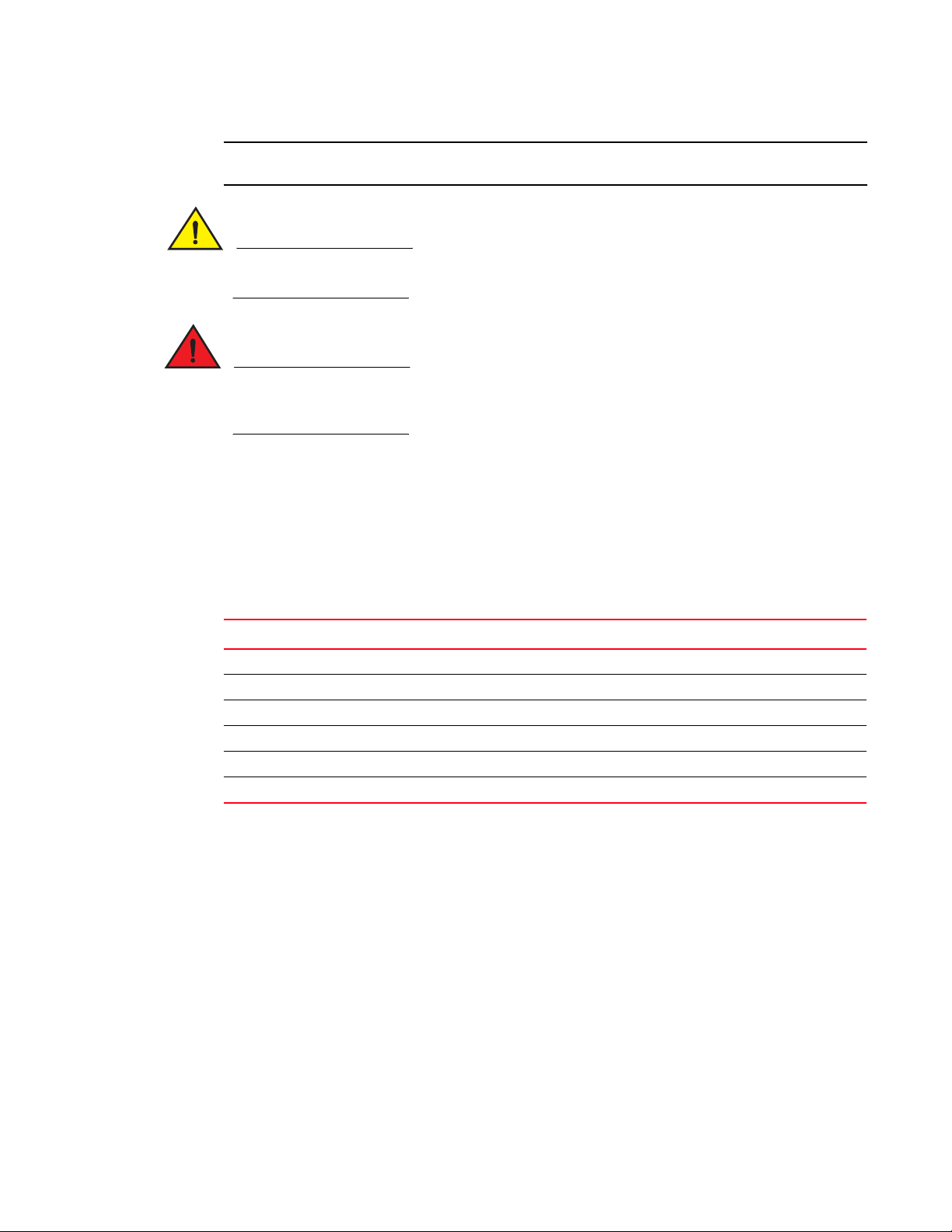
Document conventions
NOTE
This section describes text formatting conventions and important notice formats used in this document.
Text formatting
The narrative-text formatting conventions that are used are as follows:
bold text Identifies command names
italic text Provides emphasis
code text Identifies CLI output
Brocade ICX 6650 slot and Ethernet port numbering
Identifies the names of user-manipulated GUI elements
Identifies keywords and operands
Identifies text to enter at the GUI or CLI
Identifies variables
Identifies paths and Internet addresses
Identifies document titles
Identifies command syntax examples
For readability, command names in the narrative portions of this guide are presented in mixed
lettercase: for example, switchShow. In actual examples, command lettercase is all lowercase.
Command syntax conventions
Command syntax in this manual follows these conventions:
command Commands are printed in bold.
--option, option Command options are printed in bold.
-argument, arg Arguments.
[ ] Optional elements appear in brackets.
variable Variables are printed in italics. In the help pages, values are underlined
enclosed in angled brackets < >.
... Repeat the previous element, for example “member[;member...]”
value Fixed values following arguments are printed in plain font. For example,
--show WWN
| Boolean. Elements are exclusive. Example:
--show -mode egress | ingress
or
Notes, cautions, and warnings
The following notices and statements are used in this manual. They are listed below in order of
increasing severity of potential hazards.
A note provides a tip, guidance, or advice, emphasizes important information, or provides a
reference to related information.
Brocade ICX 6650 Hardware Installation Guide xiii
53-1002599-01
Page 14
Brocade ICX 6650 slot and Ethernet port numbering
ATTENTION
CAUTION
DANGER
An Attention statement indicates potential damage to hardware or data.
A Caution statement alerts you to situations that can be potentially hazardous to you or cause damage to hardware, firmware, software, or data.
A Danger statement indicates conditions or situations that can be potentially lethal or extremely hazardous to you. Safety labels are also attached directly to products to warn of these conditions or situations.
Notice to the reader
This document might contain references to the trademarks of the following corporations. These
trademarks are the properties of their respective companies and corporations.
These references are made for informational purposes only.
Corporation Referenced Trademarks and Products
Microsoft Corporation Windows, Windows NT, Internet Explorer
Oracle Corporation Oracle, Java
Netscape Communications Corporation Netscape
Mozilla Corporation Mozilla Firefox
Sun Microsystems, Inc. Sun, Solaris
Red Hat, Inc. Red Hat, Red Hat Network, Maximum RPM, Linux Undercover
Related publications
The following Brocade documents supplement the information in this guide:
• Brocade ICX 6650 Release Notes
• Brocade ICX 6650 Hardware Installation Guide New
• Brocade ICX 6650 Administration Guide
• Brocade ICX 6650 Platform and Layer 2 Configuration Guide
• Brocade ICX 6650 Layer 3 Routing Configuration Guide
• Brocade ICX 6650 Security Configuration Guide
• Brocade ICX 6650 IP Multicast Configuration Guide
xiv Brocade ICX 6650 Hardware Installation Guide
53-1002599-01
Page 15

• Brocade ICX 6650 Diagnostic Reference
• Unified IP MIB Reference
• Ports-on-Demand Licensing for the Brocade ICX 6650
The latest versions of these guides are posted at http://www.myBrocade.com/ethernetproducts.
Additional information
This section lists additional Brocade and industry-specific documentation that you might find helpful.
Brocade resources
To get up-to-the-minute information, go to http://www.myBrocade.com to register at no cost for a
user ID and password.
White papers, online demonstrations, and data sheets are available through the Brocade website
at:
Brocade ICX 6650 slot and Ethernet port numbering
http://www.myBrocade.com/products-solutions/products/index.page
For additional Brocade documentation, visit the Brocade website:
http://www.myBrocade.com
Release notes are available on the MyBrocade website.
Getting technical help
To contact Technical Support, go to
http://www.myBrocade.com/services-support/index.page
for the latest e-mail and telephone contact information.
Document feedback
Quality is our first concern at Brocade and we have made every effort to ensure the accuracy and
completeness of this document. However, if you find an error or an omission, or you think that a
topic needs further development, we want to hear from you. Forward your feedback to:
documentation@brocade.com
Provide the title and version number of the document and as much detail as possible about your
comment, including the topic heading and page number and your suggestions for improvement.
Brocade ICX 6650 Hardware Installation Guide xv
53-1002599-01
Page 16

Brocade ICX 6650 slot and Ethernet port numbering
xvi Brocade ICX 6650 Hardware Installation Guide
53-1002599-01
Page 17

Chapter
Brocade ICX 6650 Overview
In this chapter
•Brocade ICX 6650 overview . . . . . . . . . . . . . . . . . . . . . . . . . . . . . . . . . . . . . . . 1
•Views of the Brocade ICX 6650 switch . . . . . . . . . . . . . . . . . . . . . . . . . . . . . . 2
•Ports-on-Demand licensing. . . . . . . . . . . . . . . . . . . . . . . . . . . . . . . . . . . . . . . . 3
•Brocade ICX 6650 slot and Ethernet port numbering . . . . . . . . . . . . . . . . . . 4
•Supported transceivers and cables . . . . . . . . . . . . . . . . . . . . . . . . . . . . . . . . . 5
•Breakout cables. . . . . . . . . . . . . . . . . . . . . . . . . . . . . . . . . . . . . . . . . . . . . . . . . 6
Brocade ICX 6650 overview
The Brocade ICX 6650 is a high density, Top of Rack (ToR) switch that offers both 1/10 and 10/40
Gigabit Ethernet (GbE) line rate, low latency cut-through switching, with 1600 Gbps switching
capacity for campus LAN and classic Ethernet data center environments.
1
The device features:
• 56 SFP+ front-panel ports which support 1/10 GbE data rate
• Six QSFP+ rear-panel ports which support 10/40 GbE data rate
• Four 40 GbE ports support optical QSFP+ module (SR only) up to 100 meters
• Two 4x10 GbE ports that support QSFP-to-SFP breakout optical modules (SR) and
QSFP-to-SFP breakout active copper 1-meter, 3-meter, and 5-meter cables
• SFP+ port support with Brocade 1-meter, 3-meter, 5-meter active copper cables and optical
modules
• QSFP+ port support with Brocade 1-meter, 3-meter, 5-meter active copper QSFP-to-SFP
breakout cables, standard SR4 optical modules, and 4x10 GbE SR4 optical modules
• Dual redundant, hot-swappable 250W AC power supplies available with Intake or Exhaust
airflow
• Dual redundant, hot-swappable fan units available with Intake or Exhaust airflow
• One Gigabit Ethernet port (RJ45) and one serial management port to configure and manage
the switch through the CLI.
Brocade ICX 6650 Hardware Installation Guide 1
53-1002599-01
Page 18
Views of the Brocade ICX 6650 switch
7
6
8 9 10
1234
5
2
8
31
5
6 7 9
4
1
Views of the Brocade ICX 6650 switch
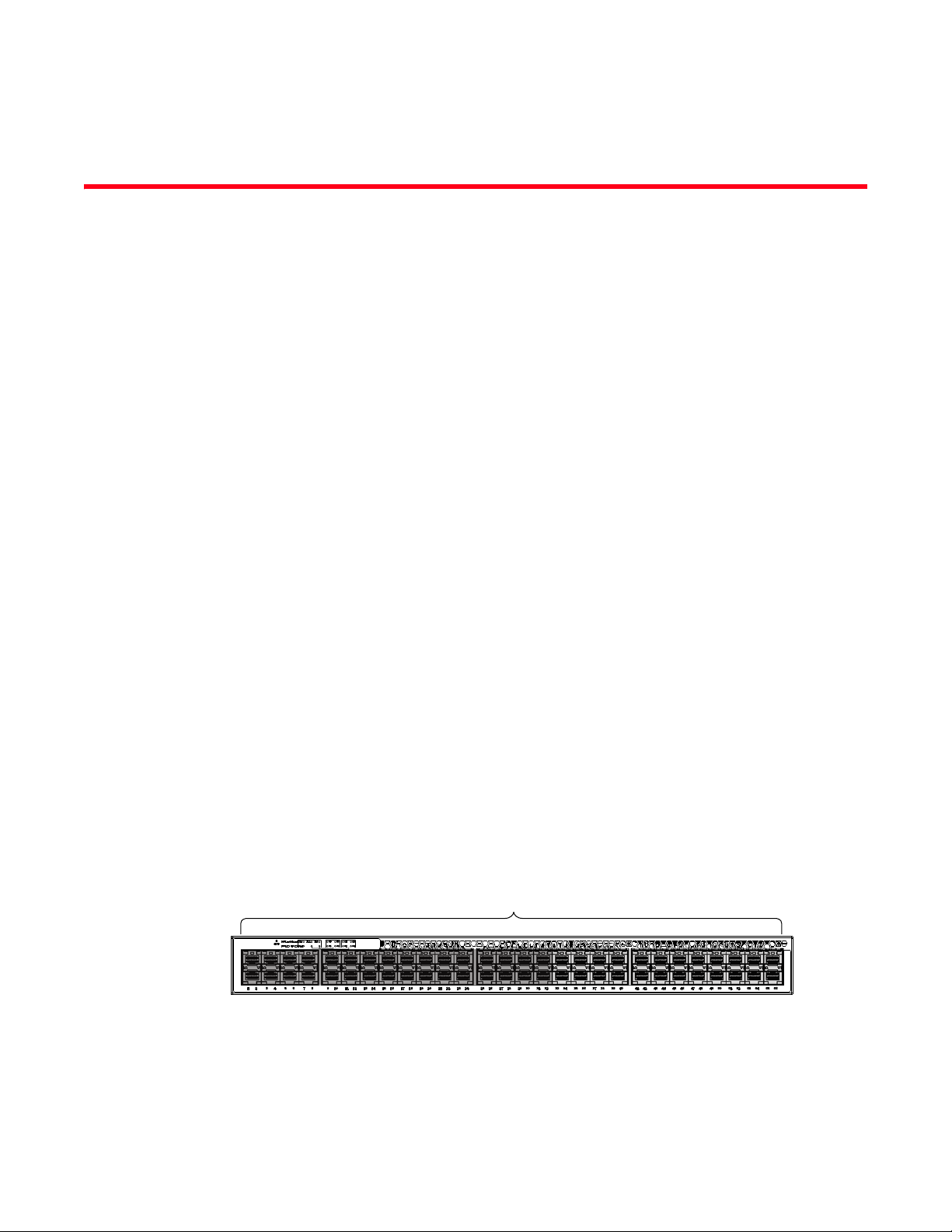
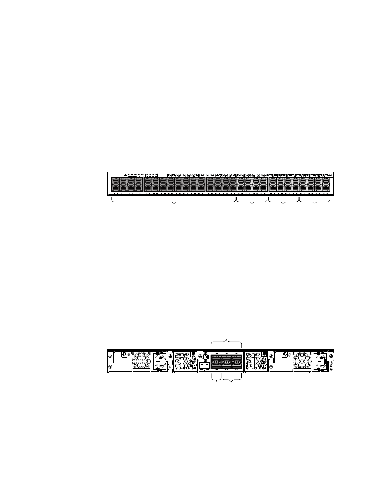
Figure 1 shows the front view of the Brocade ICX 6650 switch.
FIGURE 1 Front view of the Brocade ICX 6650
1 Push button reset 6 Air Intake/Exhaust
2 PSU1 and PSU2 status LEDs 7 Ports 1/1 through 1/32
3 DIAG/MS status LEDs 8 Ports 1/33 through 1/40
4 1x40 GbE QSFP rear port status/activity LEDs 9 Ports 1/41 through 1/48
5 4x10 GbE QSFP-to-SFP breakout port
status/activity LED
10 Ports 1/49 through 1/56
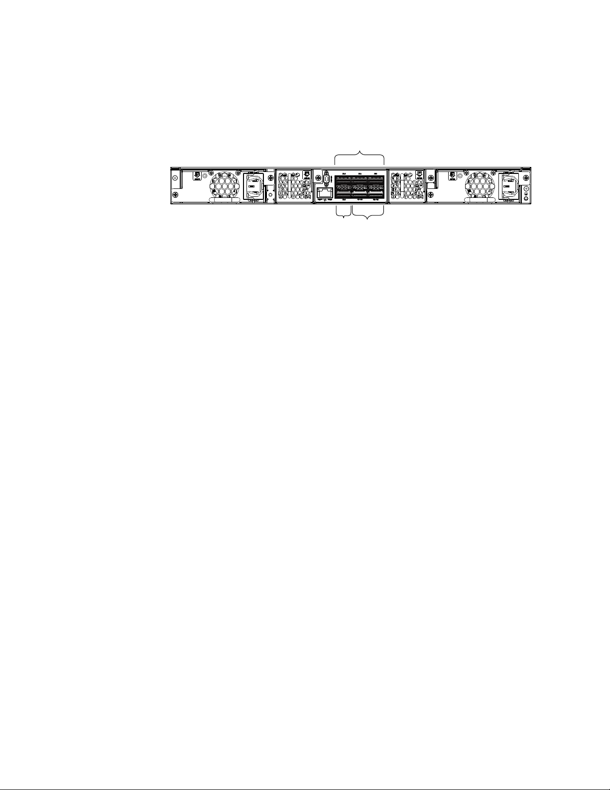
Figure 2 shows the back view of the Brocade ICX 6650 switch.
FIGURE 2 Back view of the Brocade ICX 6650
1 Fan unit 2 Ports 2/1 through 2/2
3Port 2/3 4Fan unit
5 Power supply 6 Ethernet management port
7 Port 2/4 8 Ports 3/1 through 3/8
9 Power supply
2 Brocade ICX 6650 Hardware Installation Guide
53-1002599-01
Page 19
Ports-on-Demand licensing
Base (32x10 GbE) 8x10 GbE 8x10 GbE
Blocks of 8 1/10 GbE SFP+ ports
Sequential only
33-40, 41-48, 49-56
8x10 GbE
2/1-2
2/4 3/1-8
2/3
Any pair of QSFP+ ports
2x40 GbE ports (2/1-2, 2/3-4)
2 4x10 GbE ports (3/1-4, 3/5-8)
4x10 GbE breakout ports
(3/1-4, 3/5-8)
The Brocade ICX 6650 device features Ports-on-Demand licensing. With Ports-on-Demand
licensing, software features do not require licenses and you can add port licenses as needed.
A fully populated device supports 56 front-panel, dual-speed 1/10 GbE SFP+ ports, 4 rear panel 40
GbE QSFP+ ports, and 2 rear panel 4x10 GbE QSFP+ breakout ports.
You can purchase and install Ports-on-Demand licenses in blocks of eight dual-speed 1/10 GbE
SFP+ front-panel ports. These ports are sequential, enabling ports 33 through 40, 41 through 48,
and 49 through 56. To enable additional front-panel ports requires purchasing and installing an
ICX6650-8P10G-LIC-POD license. When you purchase the license, you specify 8, 16, or 24 port
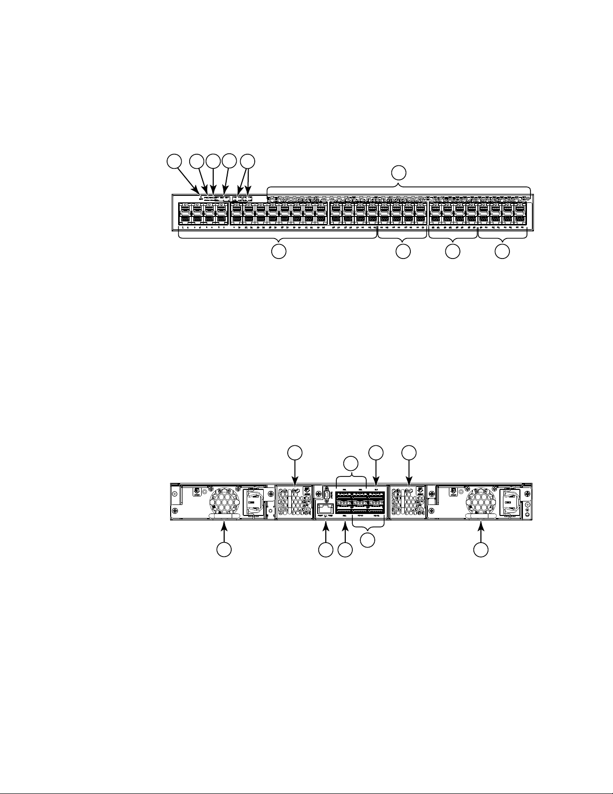
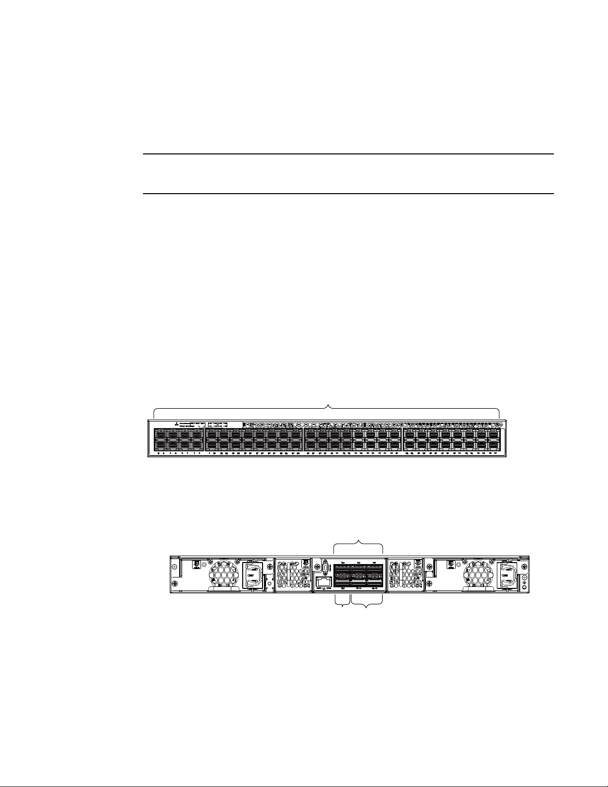
capacity so you purchase only the number of ports that you need. Figure 3 shows the front-panel
ports.
FIGURE 3 Brocade ICX 6650 front-panel ports
Ports-on-Demand licensing
1
You can purchase and install up to three ICX6650-2P40G-LIC-POD licenses to enable pairs of 40
GbE ports or 4x10 GbE breakout ports on the rear panel. An ICX6650-2P40G-LIC-POD license can
be applied to any of the following pairs of 40 GbE rear-panel ports or 4x10 GbE breakout ports:
• 2/1 and 2/2 40 GbE rear-panel ports
• 2/3 and 2/4 40 GbE rear-panel ports
• 3/1-4 and 3/5-8 4x10 GbE rear-panel breakout ports
Figure 4 shows the rear-panel ports.
FIGURE 4 Brocade ICX 6650 rear-panel ports
Brocade ICX 6650 Hardware Installation Guide 3
53-1002599-01
Page 20
Brocade ICX 6650 slot and Ethernet port numbering
NOTE
Slot 1
Slot 2
Slot 2 Slot 3
1
The breakout ports support either:
• Direct-attached copper breakout cables QSPF+ to 4 SFP+ (Part number
40G-QSFP-4SFP-C-/0101/0301/0501)
• Breakout capable SR4 QSPF+ optical transceiver (Part number 40G-QSFP-SR4-INT)
You can add a ICX6650-2P40G-LIC-POD license to any configuration. For example you can add a
ICX6650-2P40G-LIC-POD license to a base 32 port configuration.
No trial licenses are available with Ports-on-Demand licensing.
Brocade ICX 6650 slot and Ethernet port numbering
Many CLI commands require users to enter port numbers as part of the command syntax, and
many show command outputs display port numbers. The port numbers are entered and displayed
in stack-unit/slot number/port number format. In all Brocade ICX 6650 inputs and outputs, the
stack-unit number is always 1.
The ICX 6650 contains the following slots and Ethernet ports:
• Slot 1 is located on the front of the ICX 6650 device and contains ports 1 through 56. Ports 1
through 32 are 10 GbE. Ports 33 through 56 are 1/10 GbE SFP+ ports. Refer to the following
figure.
• Slot 2 is located on the back of the ICX 6650 device and contains ports 1 through 3 on the top
row and port 4 on the bottom row. These ports are 2x40 GbE QSFP+. Refer to the following
figure.
• Slot 3 is located on the back of the ICX 6650 device and contains ports 1 through 8. These
ports are 4 x 10 GbE breakout ports and require the use of a breakout cable. Refer to the
previous figure.
4 Brocade ICX 6650 Hardware Installation Guide
53-1002599-01
Page 21

Supported transceivers and cables
The Brocade ICX 6650 supports the following transceivers and cables:
• 1 GbE
• SX
• LX
• Copper
• 10 GbE
• SFP+: USR, Short Reach, Long Reach
• Active Twinax copper (1 meter, 3 meter, and 5 meter)
• 40 GbE
• Standard 40 GbE [SR4] transceiver without breakout
• 40 GbE [SR4] QSFP+ transceiver with breakout to 4x10 GbE up to 100 meter on OM3 fiber
• 40 GbE copper [D.A.C] breakout (1 meter, 3 meter, and 5 meter)
Non-branded active twinax cables can be used, but Brocade does not support them.
Supported transceivers and cables
1
Brocade ICX 6650 Hardware Installation Guide 5
53-1002599-01
Page 22
Breakout cables
P1
P2
P3
P4
P1
P2
P3
P4
P5
P6
P8
P7
1
Breakout cables
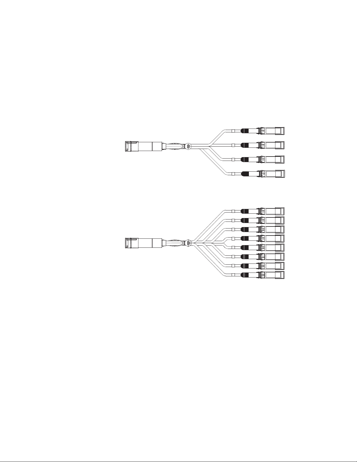
The rear panel of the Brocade ICX 6650 device contains two 4x10 GbE ports which support the following:
• QSFP+ to 4 SFP+ (4 x 10 GbE) direct attach copper breakout cables (see Figure 5)
• QSFP+ (MTP 1 x 8 or 1 x 12) optical breakout cables (see Figure 6)
FIGURE 5 QSFP+ to 4 SFP+ (4 x 10 GbE) direct attach copper breakout cable
FIGURE 6 QSFP+ (MTP 1 x 8 or 1 x 12) optical breakout cable
6 Brocade ICX 6650 Hardware Installation Guide
53-1002599-01
Page 23
Chapter
CAUTION
CAUTION
Installing the Brocade ICX 6650
In this chapter
•Unpacking the device . . . . . . . . . . . . . . . . . . . . . . . . . . . . . . . . . . . . . . . . . . . . 7
•Installation and safety considerations . . . . . . . . . . . . . . . . . . . . . . . . . . . . . . . 8
•Installation tasks . . . . . . . . . . . . . . . . . . . . . . . . . . . . . . . . . . . . . . . . . . . . . . . 10
•Installation precautions . . . . . . . . . . . . . . . . . . . . . . . . . . . . . . . . . . . . . . . . . 10
•Installing the device in a rack or cabinet. . . . . . . . . . . . . . . . . . . . . . . . . . . . 12
•Attaching a PC or terminal . . . . . . . . . . . . . . . . . . . . . . . . . . . . . . . . . . . . . . . 17
•Powering on the system . . . . . . . . . . . . . . . . . . . . . . . . . . . . . . . . . . . . . . . . . 17
•Installing an SFP+ transceiver . . . . . . . . . . . . . . . . . . . . . . . . . . . . . . . . . . . . 18
The procedures in this manual are intended for qualified service personnel.
2
Before beginning the installation, see the precautions in “Power precautions” on page 11.
Unpacking the device
The Brocade ICX 6650 device ships with all of the items listed below. Verify the contents of your
shipping container. If any items are missing, please contact the place of purchase.
Package contents
The following items are included in your shipping carton:
• A Brocade ICX 6650 device
• One accessory kit, containing the following items:
• One power cord
• One RJ45 to DB9F adaptor
• One RJ45 crossover cable
• One mini-USB (M)-DB9(F) cable
• Two mounting ears and screws
• Grounding terminal
Brocade ICX 6650 Hardware Installation Guide 7
53-1002599-01
Page 24

Installation and safety considerations
2
Installation and safety considerations
You can install the Brocade ICX 6650 in the following ways:
• As a standalone unit on a flat surface.
• In an EIA cabinet using a fixed-rail rack mount kit. The optional fixed-rail rack mount kit can be
ordered from your switch retailer. Both the 24”-28” rack depth kit and the 28”-32” rack depth
kit will work with the ICX 6650 device.
• In a 2-post Telco rack using a flush mount rack kit. The optional flush mount rack kit for
switches can be ordered from your switch retailer.
• In a 2-post Telco rack using a mid-mount rack kit. The optional mid-mount rack kit for switches
can be ordered from your switch retailer.
Electrical considerations
To install and operate the switch successfully, ensure compliance with the following requirements:
• The primary outlet is correctly wired, protected by a circuit breaker, and grounded in
accordance with local electrical codes.
• The supply circuit, line fusing, and wire size are adequate, as specified by the electrical rating
on the switch nameplate.
• The power supply standards are met.
Environmental considerations
For successful installation and operation of the switch, ensure that the following environmental
requirements are met:
• Because the Brocade ICX 6650 can be ordered with fans that move air either front to back or
back to front, be sure to orient your switch with the airflow pattern of any other devices in the
rack. All equipment in the rack should force air in the same direction to avoid intake of exhaust
air.
• The ambient air temperature does not exceed 40C (104F) while the switch is operating.
Location Considerations
Before installing the device, plan its location and orientation relative to other devices and
equipment. Devices can be mounted in a standard 19-inch equipment rack or on a flat surface. Be
sure to follow the guidelines below when choosing a location.
The site should meet the following requirements:
• Maintain the operating environment as specified in the section “Environmental
considerations” on page 45.
• Allow a minimum of 3 in. of space between the front and the back of the device and walls or
other obstructions for proper air flow.
• Allow at least 3 in. of space at the front and back of the device for the twisted-pair, fiber-optic,
and power cabling.
• Be accessible for installing, cabling and maintaining the devices.
8 Brocade ICX 6650 Hardware Installation Guide
53-1002599-01
Page 25

Installation and safety considerations
NOTE
2
• Allow the status LEDs to be clearly visible.
• Allow for twisted-pair cable to be always routed away from power lines, fluorescent lighting
fixtures and other sources of electrical interference, such as radios and transmitters.
• Allow for the unit to be connected to a separate grounded power outlet that provides 100 to
240 VAC, 50 to 60 Hz, is within 2 m (6.6 feet) of each device, and is powered from an
independent circuit breaker. As with any equipment, a filter or surge suppressor is
recommended.
• Some combinations of intake and exhaust airflows may not be compatible with your
environment. Consult your fan and power supply module FRU kit to determine the correct
configuration.
• For a 4-post rail mount configuration, order the appropriate mounting kit and refer to the kit
documentation.
Cabinet considerations
For successful installation and operation of the switch in a cabinet, ensure the following cabinet
requirements are met:
• The cabinet must be a standard EIA cabinet.
• The equipment in the cabinet is grounded through a reliable branch circuit connection and
maintains ground at all times. Do not rely on a secondary connection to a branch circuit, such
as a power strip.
• Airflow and temperature requirements are met on an ongoing basis, particularly if the switch is
installed in a closed or multicabinet assembly.
• The additional weight of the switch does not exceed the cabinet’s weight limits or unbalance
the cabinet in any way.
• The cabinet is secured to ensure stability in case of unexpected movement, such as an
earthquake.
Recommendations for cable management
Cables can be organized and managed in a variety of ways; for example, use cable channels on the
sides of the cabinet or patch panels to reduce the potential for tangling the cables. The following
list provides some recommendations for cable management:
You should not use tie wraps with optical cables because they are easily overtightened and can
damage the optic fibers. Velcro-like wraps are recommended.
• Plan for the rack space required for cable management before installing the switch.
• Leave at least 1 m (3.28 ft) of slack for each port cable. This provides room to remove and
replace the switch, allows for inadvertent movement of the rack, and helps prevent the cables
from being bent to less than the minimum bend radius.
• For easier maintenance, label the cables and record the devices to which they are connected.
• Keep LEDs visible by routing port cables and other cables away from the LEDs.
Brocade ICX 6650 Hardware Installation Guide 9
53-1002599-01
Page 26

Installation tasks
CAUTION
2
Installation tasks
Follow the steps listed in Table 1 to install your device. Details for each of these steps are provided
on the pages indicated.
TABLE 1 Installation tasks
Task
Number
Task Where to Find More Information
1 Ensure that the physical environment that will host the
device has the proper cabling and ventilation.
2 Install the device in an equipment rack. “Installing the device in a rack or cabinet”
3 Attach a terminal or PC to the device. This will enable you
to configure the device through the Command Line
Interface (CLI).
4 Plug the device into a nearby power source that adheres to
the regulatory requirements outlined in this manual.
5 No default password is assigned to the CLI. For additional
access security, assign a password.
6 Before attaching equipment to the device, you need to
configure an interface IP address to the subnet on which
the device will be located. Initial IP address configuration
is performed using the CLI with a direct serial connection.
Subsequent IP address configuration can be performed
using the Web management interface.
8 Once you power on the device and assign IP addresses,
the system is ready to accept network equipment.
9 Test IP connectivity to other devices by pinging them and
tracing routes.
10 Continue configuring the device using the CLI or the Web
management interface.
11 Secure access to the device. Brocade ICX 6650 Administration Guide
“Environmental considerations” on page 8
on page 12
“Attaching a PC or terminal” on page 17
“Powering on the system” on page 17
“Setting passwords” on page 21
“Configuring IP addresses” on page 22
“Devices running Layer 3 software” on
page 23
“Testing connectivity” on page 28
Brocade ICX 6650 Administration Guide
Installation precautions
Follow all precautions when installing a device.
General precautions
All fiber-optic interfaces use Class 1 lasers.
10 Brocade ICX 6650 Hardware Installation Guide
53-1002599-01
Page 27

Installation precautions
CAUTION
CAUTION
CAUTION
CAUTION
CAUTION
CAUTION
CAUTION
2
Do not install the device in an environment where the operating ambient temperature might
exceed 40
Make sure the air flow around the front and sides of the device is not restricted.
Never leave tools inside the device.
Risk of explosion if battery is replaced by an incorrect type. Dispose of used batteries according to the instructions.
C (104
F).
Lifting precautions
Make sure the rack or cabinet housing the device is adequately secured to prevent it from becoming unstable or falling over.
Power precautions
Use a separate branch circuit for each AC power cord, which provides redundancy in case one of the circuits fails.
To avoid high voltage shock, do not open the device while the power is on.
Brocade ICX 6650 Hardware Installation Guide 11
53-1002599-01
Page 28

Installing the device in a rack or cabinet
CAUTION
CAUTION
CAUTION
CAUTION
NOTE
2
Ensure that the device does not overload the power circuits, wiring, and over-current protection.
To determine the possibility of overloading the supply circuits, add the ampere (amp) ratings of all
devices installed on the same circuit as the device. Compare this total with the rating limit for the
circuit. The maximum ampere ratings are usually printed on the devices near the input power
connectors.
Disconnect the power cord from all power sources to completely remove power from the device.
If the installation requires a different power cord than the one supplied with the device, make
sure you use a power cord displaying the mark of the safety agency that defines the regulations
for power cords in your country. The mark is your assurance that the power cord can be used
safely with the device.
Installing the device in a rack or cabinet
Make sure the rack or cabinet housing the device is adequately secured to prevent it from becoming unstable or falling over.
You need a #2 Phillips screwdriver for installation.
Before mounting the switch in a rack, pay particular attention to the following factors:
• Temperature: Since the temperature within a rack assembly may be higher than the ambient
room temperature, check that the rack-environment temperature is within the specified
operating temperature range. (Refer to “Operating Environment” on page 45.)
• Mechanical loading: Do not place any equipment on top of a rack-mounted unit.
• Circuit overloading: Be sure that the supply circuit to the rack assembly is not overloaded.
• Grounding: Rack-mounted equipment should be properly grounded. Particular attention should
be given to supply connections other than direct connections to the mains.
12 Brocade ICX 6650 Hardware Installation Guide
53-1002599-01
Page 29

Installing the device in a rack or cabinet
NOTE
123
2
2-Post rack mount installation
Use the following procedure when installing the Brocade ICX 6650 device in a 2-post rack. For 4-post
racks, follow the procedures in the section “4-Post rack mount installation” on page 14.
Remove the rack mount kit from the shipping carton. The kit contains the following:
• Two L-shaped mounting brackets.
• Sixteen 8-32 x 5/16 in., panhead Phillips screws with patchlocks.
• Four 10-32 x 5/8 in., panhead Phillips screws (torque to 25 in-lb, 29 cm-kg). See item 1 in
Figure 7.
• Eight 32-10 retainer nuts (for square-hole rack rails). See item 2 in Figure 7.
• Eight 32-10 retainer nuts (for round-hole rack rails) See item 3 in Figure 7.
FIGURE 7 2-post screws and retainer nuts
Use the following steps to mount devices in a 2-post rack.
1. Attach the mounting brackets to the sides of the device as illustrated in Figure 8 using the 8-32 x 5/16 in. screws.
FIGURE 8 Attaching the brackets for Brocade ICX 6650 devices
Brocade ICX 6650 Hardware Installation Guide 13
53-1002599-01
Page 30

Installing the device in a rack or cabinet
NOTE
2
2. Position the switch in the cabinet, providing temporary support under the switch until the rail kit is secured to the cabinet.
3. Attach the front right bracket to the rail rack using two 10-32 x 5/8 in. screws and the appropriate round or square retainer nuts.
4. Repeat step 3 to attach the left front bracket to the left front rack rail and tighten all 10-32 x 5/8 in. screws to a torque of 25 in-lb (29 cm-kg). See Figure 9.
FIGURE 9 Installing the device in a 2-post rack
5. Proceed to “Attaching a PC or terminal” on page 17.
4-Post rack mount installation
Kits for 4-post rack mounting are not included in the shipping carton and must be ordered separately.
Use the following procedure when installing the Brocade ICX 6650 device in a 4-post rack cabinet.
For 2-post cabinets, follow the procedures in the section “2-Post rack mount installation” on
page 13.
14 Brocade ICX 6650 Hardware Installation Guide
53-1002599-01
Page 31

Installing the device in a rack or cabinet
CAUTION
123
Remove the rack mount kit from the shipping carton. The kit contains the following:
• Two L-shaped mounting brackets.
• Four rack mount rails: two for side attach and two for rear attach racks.
• Thirty-two 8-32 x 5/16 in., panhead Phillips screws with patchlocks.
• Eight 10-32 x 5/8 in., panhead Phillips screws (torque to 25 in-lb, 29 cm-kg). See item 1 in
Figure 10.
• Eight 32-10 retainer nuts (for square-hole rack rails). See item 2 in Figure 10.
• Eight 32-10 retainer nuts (for round-hole rack rails) See item 3 in Figure 10.
FIGURE 10 4-post screws and retainer nuts
Use the following steps to mount devices in a 4-post rack.
2
Do not use the hardware supplied in a 2-post rack mounting kit to mount a Brocade ICX 6650
device in a 4-post rack. Mounting the device in a 4-post rack requires additional hardware to
prevent drooping from possible flexing and distortion of the 4-post rack when a device is not
properly installed.
1. Attach the mounting brackets to the sides of the device as illustrated in Figure 8 above using the 8-32 x 5/16 in. screws.
2. Attach the appropriate rails: either side attach or rear attach at determined by the type of rack in which you are installing the device.
Figure 11 and Figure 12 show exploded views of the optional 4-post rack mount kit.
Brocade ICX 6650 Hardware Installation Guide 15
53-1002599-01
Page 32

Installing the device in a rack or cabinet
2
FIGURE 11 Optional 4-post Rack Mount Kit, Rear Attach
FIGURE 12 Optional 4-post Rack Mount Kit, Side Attach
3. Position the switch in the cabinet, providing temporary support under the switch until the rail kit is secured to the cabinet.
4. Attach the front right bracket to the rail rack using two 10-32 x 5/8 in. screws and the appropriate round or square retainer nuts.
5. Repeat step 3 to attach the left front bracket to the left front rack rail and tighten all 10-32 x 5/8 in. screws to a torque of 25 in-lb (29 cm-kg). See Figure 9.
16 Brocade ICX 6650 Hardware Installation Guide
53-1002599-01
Page 33

6. Attach the rear right bracket to the rail rack using two 10-32 x 5/8 in. screws and the
NOTE
NOTE
appropriate round or square retainer nuts.
7. R ep e at step 6 to attach the left front bracket to the left front rack rail and tighten all 10-32 x 5/8 in. screws to a torque of 25 in-lb (29 cm-kg).
8. Proceed to “Attaching a PC or terminal” on page 17.
Attaching a PC or terminal
To assign an IP address, you must have access to the Command Line Interface (CLI). The CLI is a
text-based interface that can be accessed through a direct serial connection to the device and
through Telnet connections. The CLI is described in detail in the Brocade ICX 6650 Administration
Guide.
Access the CLI by connecting to the console port. After you assign an IP address, you can access
the system through Telnet, the Web management interface, or Brocade Network Advisor.
Use the following steps to attach a management station to the console port:
1. Connect a PC or terminal to the console management port on the back of the ICX 6650 device using the mini-USB serial console port cable (Part number 50-1000059-01.
Attaching a PC or terminal
2
For port pinout information for the mini-USB serial console port, see the section “Pinouts and
signalling” on page 50.
You need to run a terminal emulation program on the PC.
2. Launch the terminal emulation program and set the following session parameters:
• Baud: 9600 bps
• Data bits: 8
• Parity: None
• Stop bits: 1
• Flow control: None
The console serial communication port serves as a connection point for management by a PC.
Powering on the system
After you complete the physical installation, you can power on the system.
1. Remove the power cable from the shipping package.
2. Attach the AC power cable to the AC connector on the rear panel.
3. Insert the power cable plug into a 100V-240V outlet.
To turn the system off, simply unplug the power cable or cables.
Brocade ICX 6650 Hardware Installation Guide 17
53-1002599-01
Page 34

Installing an SFP+ transceiver
NOTE
NOTE
!
2
The socket should be installed near the equipment and should be easily accessible.
Installing an SFP+ transceiver
To monitor the transceivers, the showmedia command output shows the transceiver information
for all interfaces on the switch. Third party transceivers are allowed. Brocade will provide support
for such a system but may require that a Brocade transceiver be used for troubleshooting.
Support will not be provided if there is an issue with the third party transceiver.
Complete the following steps to install an SFP+ transceiver.
1. Remove any protector plugs from the transceivers and the ports.
2. Making sure that the bail (wire handle) is in the unlocked position, place the SFP+ transceiver in the correctly oriented position on the port, as shown in Figure 13.
3. Slide the SFP+ transceiver into the port until you feel it click into place; then close the bail.
Each SFP+ transceiver has a 10-pad gold-plated edge connector on the bottom. The correct
position to insert an SFP+ transceiver in the upper row of ports is with the gold-plated edge down.
The correct position to insert an SFP+ transceiver in the lower row of ports is with the gold-plated
edge up.
FIGURE 13 Installing an SFP+ transceiver in a port slot
18 Brocade ICX 6650 Hardware Installation Guide
53-1002599-01
Page 35

Chapter
Slot 1
Configuring the Brocade ICX 6650
In this chapter
•Brocade ICX 6650 slot and Ethernet port numbering . . . . . . . . . . . . . . . . . 19
•Assigning permanent passwords . . . . . . . . . . . . . . . . . . . . . . . . . . . . . . . . . . 20
•Configuring IP addresses . . . . . . . . . . . . . . . . . . . . . . . . . . . . . . . . . . . . . . . . 22
•Connecting network devices. . . . . . . . . . . . . . . . . . . . . . . . . . . . . . . . . . . . . . 26
•Testing connectivity. . . . . . . . . . . . . . . . . . . . . . . . . . . . . . . . . . . . . . . . . . . . . 28
•Troubleshooting network connections . . . . . . . . . . . . . . . . . . . . . . . . . . . . . . 28
Brocade ICX 6650 slot and Ethernet port numbering
Many CLI commands require users to enter port numbers as part of the command syntax, and
many show command outputs display port numbers. The port numbers are entered and displayed
in stack-unit/slot number/port number format. In all Brocade ICX 6650 inputs and outputs, the
stack-unit number is always 1.
3
The ICX 6650 contains the following slots and Ethernet ports:
• Slot 1 is located on the front of the ICX 6650 device and contains ports 1 through 56. Ports 1
through 32 are 10 GbE. Ports 33 through 56 are 1/10 GbE SFP+ ports. Refer to the following
figure.
Brocade ICX 6650 Hardware Installation Guide 19
53-1002599-01
Page 36

Assigning permanent passwords
NOTE
Slot 2
Slot 2 Slot 3
3
• Slot 2 is located on the back of the ICX 6650 device and contains ports 1 through 3 on the top
row and port 4 on the bottom row. These ports are 2x40 GbE QSFP+. Refer to the following
figure.
• Slot 3 is located on the back of the ICX 6650 device and contains ports 1 through 8. These
ports are 4 x 10 GbE breakout ports and require the use of a breakout cable. Refer to the
previous figure.
Assigning permanent passwords
By default, the CLI is not protected by passwords. To secure CLI access, Brocade strongly
recommends assigning passwords. See the Brocade ICX 6650 Administration Guide.
The CLI contains the following access levels:
• User EXEC – The level you enter when you first start a CLI session. At this level, you can view
some system information but you cannot configure system or port parameters.
• Privileged EXEC – This level is also called the Enable level and can be secured by a password.
You can perform tasks such as manage files on the flash module, save the system
configuration to flash, and clear caches at this level.
• CONFIG – The configuration level. This level lets you configure the system IP address and
configure switching and routing features. To access the CONFIG mode, you must already be
logged into the Privileged level of the EXEC mode.
You can set the following levels of Enable passwords:
• Super User – Allows complete read-and-write access to the system. This is generally for system
administrators and is the only password level that allows you to configure passwords.
You must set a super user password before you can set other types of passwords.
• Port Configuration – Allows read-and-write access for specific ports but not for global
(system-wide) parameters.
• Read Only – Allows access to the Privileged EXEC mode and CONFIG mode but only with read
access.
20 Brocade ICX 6650 Hardware Installation Guide
53-1002599-01
Page 37

Assigning permanent passwords
NOTE
NOTE
NOTE
3
Setting passwords
1. At the opening CLI prompt, enter the following command to change to the Privileged level of the EXEC mode:
Brocade> enable
2. Access the CONFIG level of the CLI by entering the following command:
Brocade# configure terminal
Brocade(config)#
3. Enter the following command to set the super user password:
Brocade(config)# enable super-user-password text
You must set the super user password before you can set other types of passwords.
4. Enter the following commands to set the port configuration and read-only passwords:
Brocade(config)# enable port-config-password text
Brocade(config)# enable read-only-password text
If you forget your super user password, refer to “Recovering from a lost password” on page 21.
Syntax: enable super-user-password | read-only-password | port-config-password text
Passwords can be up to 32 characters long.
Recovering from a lost password
By default, the CLI does not require passwords. However, if someone has configured a password for
the device but the password has been lost, you can regain super user access to the device using
the following procedure.
Recovery from a lost password requires direct access to the serial port and a system reset.
Use the following procedure to recover from a lost password.
1. Start a CLI session over the serial interface to the Brocade device.
2. Reboot the device.
3. While the system is booting, before the initial system prompt appears, enter b to enter the boot monitor mode.
4. Enter no password at the prompt. (You cannot abbreviate this command.)
After the console prompt reappears, assign a new password.
Brocade ICX 6650 Hardware Installation Guide 21
53-1002599-01
Page 38

Configuring IP addresses
CAUTION
NOTE
3
Configuring IP addresses
You must configure at least one IP address using the serial connection to the CLI before you can
manage the system using the other management interfaces.
Brocade devices support both classical IP network masks (Class A, B, and C subnet masks, and so
on) and Classless Interdomain Routing (CIDR) network prefix masks.
• To enter a classical network mask, enter the mask in IP address format. For example, enter
“209.157.22.99 255.255.255.0” for an IP address with a Class-C subnet mask.
• To enter a prefix number for a network mask, enter a forward slash ( / ) and the number of bits
in the mask immediately after the IP address. For example, enter “209.157.22.99/24” for an
IP address that has a network mask with 24 significant (“mask”) bits.
By default, the CLI displays network masks in classical IP address format (example:
255.255.255.0). You can change the display to the prefix format. See the Brocade ICX 6650
Administration Guide.
Devices running Layer 2 software
Use the following procedure to configure an IP address on a device running Layer 2 software.
1. At the opening CLI prompt, enter enable.
Brocade> enable
2. Enter the following command at the CLI Privileged EXEC level prompt, then press Enter. This command erases the factory test configuration if still present:
Brocade# erase startup-config
Use the erase startup-config command only for new systems. If you enter this command on a
system you have already configured, the command erases the configuration. If you accidentally
do erase the configuration on a configured system, enter the write memory command to save the
running configuration to the startup-config file.
3. Access the configuration level of the CLI by entering the following command:
Brocade# configure terminalPrivileged EXEC Level
Brocade(config)# Global CONFIG Level
4. Configure the IP addresses and mask for the switch.
Brocade(config-if-e1000-2)# ip address 192.168.0.0 255.255.255.0
5. Set a default gateway address for the switch.
Brocade(config)# ip default-gateway 192.168.0.0
You do not need to assign a default gateway address for single subnet networks.
Syntax: enable [password]
Syntax: configure terminal
22 Brocade ICX 6650 Hardware Installation Guide
53-1002599-01
Page 39

Configuring IP addresses
CAUTION
NOTE
Syntax: [no] ip address ip-addr ip-mask
or
Syntax: [no] ip address ip-addr/mask-bits]
Syntax: ip default-gateway ip-addr
3
Devices running Layer 3 software
Before attaching equipment to a Brocade ICX 6650 switch, you must assign an interface IP address
to the subnet on which the router will be located. You must use the serial connection to assign the
first IP address. For subsequent addresses, you also can use the CLI through Telnet or the Web
management interface.
By default, you can configure up to 24 IP addresses on each port, virtual interface, and loopback
interface. You can increase this amount to up to 64 IP subnet addresses per port by increasing the
size of the subnet-per-interface table.
The following procedure shows how to add an IP address and mask to a router port.
1. At the opening CLI prompt, enter enable.
Brocade> enable
2. Enter the following command at the CLI Privileged EXEC level prompt, then press Enter. This command erases the factory test configuration if still present:
Brocade# erase startup-config
Use the erase startup-config command only for new systems. If you enter this command on a
system you have already configured, the command erases the configuration. If you accidentally
do erase the configuration on a configured system, enter the write memory command to save the
running configuration to the startup-config file.
3. Access the configuration level of the CLI by entering the following command:
Brocade# configure terminalPrivileged EXEC Level
Brocade(config)# Global CONFIG Level
4. Configure the IP addresses and mask addresses for the interfaces on the router.
Brocade(config)# int e 1/1/1
Brocade(config-if-e1000-2)# ip address 192.168.0.0 255.255.255.0
You can use the syntax ip address ip-addr/mask-bits if you know the subnet mask length. In
the above example, you could enter ip address 192.168.0.0/24.
Syntax: enable [password]
Syntax: configure terminal
Syntax: [no] ip address ip-addr ip-mask [secondary]
or
Brocade ICX 6650 Hardware Installation Guide 23
53-1002599-01
Page 40

Configuring IP addresses
NOTE
NOTE
3
Syntax: [no] ip address ip-addr/mask-bits [secondary]
Use the secondary parameter if you have already configured an IP address within the same
subnet on the interface.
Configuring IP parameters for devices running Layer 3 software
This section describes how to configure IP parameters for devices running Layer 3 software.
Configuring IP addresses
You can configure an IP address on the following types of Layer 3 switch interfaces:
• Ethernet port
• Virtual routing interface (also called a Virtual Ethernet or “VE”)
• Loopback interface
By default, you can have up to 24 IP addresses on each interface, but you can increase this number
to 128 IP addresses.
Once you configure a virtual routing interface on a VLAN, you cannot configure Layer 3 interface
parameters on individual ports in the VLAN. Instead, you must configure the parameters on the
virtual routing interface itself.
Brocade devices support both classical IP network masks (Class A, B, and C subnet masks, and so
on) and Classless Interdomain Routing (CIDR) network prefix masks.
• To enter a classical network mask, enter the mask in IP address format. For example, enter
“209.157.22.99 255.255.255.0” for an IP address with a Class-C subnet mask.
• To enter a prefix network mask, enter a forward slash ( / ) and the number of bits in the mask
immediately after the IP address. For example, enter “209.157.22.99/24” for an IP address
that has a network mask with 24 significant bits (ones).
By default, the CLI displays network masks in classical IP address format (for example:
255.255.255.0). You can change the display to prefix format.
Assigning an IP address to an Ethernet port
Enter the following commands to assign an IP address to port 1/1/1.
Brocade(config)# interface ethernet 1/1/1
Brocade(config-if-1/1/1)# ip address 192.168.0.0 255.255.255.0
You also can enter the IP address and mask in CIDR format, as follows:
Brocade(config-if-1/1/1)# ip address 192.168.0.0/24
Syntax: [no] ip address ip-addr ip-mask
or
Syntax: [no] ip address ip-addr/mask-bits
24 Brocade ICX 6650 Hardware Installation Guide
53-1002599-01
Page 41

Configuring IP addresses
NOTE
NOTE
3
Assigning an IP address to a loopback interface
Loopback interfaces are always up, regardless of the states of physical interfaces. They can add
stability to the network because they are not subject to route flap problems that can occur due to
unstable links between a Layer 3 Switch and other devices. You can configure up to four loopback
interfaces on a Layer 3 switch.
You can add up to 24 IP addresses to each loopback interface.
If you configure the device to use a loopback interface to communicate with a BGP4 neighbor, you
must also configure a loopback interface on the neighbor and configure the neighbor to use that
loopback interface to communicate with the Brocade switch.
To add a loopback interface, enter commands such as those shown in the following example:
Brocade(config)# int loopback 1
Brocade(config-lbif-1)# ip address 192.168.0.0/24
Syntax: interface loopback num
The num parameter specifies the virtual interface number. You can specify from 1 to the maximum
number of virtual interfaces supported on the device. To display the maximum number of virtual
interfaces supported on the device, enter the show default values command. The maximum is
listed in the System Parameters section, in the Current column of the virtual-interface row.
Assigning an IP address to a virtual routing interface
A virtual interface is a logical port associated with a Layer 3 Virtual LAN (VLAN) configured on a
Layer 3 switch. You can configure routing parameters on the virtual interface to enable the Layer 3
switch to route protocol traffic from one Layer 3 VLAN to the other, without using an external router.
This section describes how to configure an IP address on a virtual interface.
The switch uses the lowest MAC address on the device (the MAC address of port 1 or 1/1/1) as the
MAC address for all ports within all virtual interfaces you configure on the device.
Enter commands similar to the following to add a virtual interface to a VLAN and configure an IP
address on the interface.
Brocade(config)# vlan 2 name IP-Subnet_1.1.2.1/24
Brocade(config-vlan-2)# untag 1/1/1 to 1/1/4
Brocade(config-vlan-2)# router-interface ve1
Brocade(config-vlan-2)# interface ve1
Brocade(config-vif-1)# ip address 1.1.2.1/24
The first two commands in this example create a Layer 3 protocol-based VLAN name
“IP-Subnet_1.1.2.1/24” and add a range of untagged ports to the VLAN. The router-interface
command creates virtual interface 1 as the routing interface for the VLAN. The last two commands
change to the interface configuration level for the virtual interface and assign an IP address to the
interface.
Syntax: router-interface ve num
Syntax: interface ve num
Brocade ICX 6650 Hardware Installation Guide 25
53-1002599-01
Page 42

Connecting network devices
3
Deleting an IP address
Enter a command similar to the following to delete an IP address.
Brocade(config-if-1/1/1)# no ip address 1.1.2.1
This command deletes IP address 1.1.2.1. You do not need to enter the subnet mask.
To delete all IP addresses from an interface, enter the following command:
Brocade(config-if-1/1/1)# no ip address *
Syntax: no ip address ip-addr | *
Connecting network devices
Brocade devices support connections to other vendors’ routers, switches, and hubs, as well other
Brocade devices.
Connectors
For port pinouts, refer to “Pinouts and signalling” on page 50.
Connecting a network device to a fiber port
For direct attachment from the device to a Gbps NIC, switch, or router, using a fiber optic
transceiver, you will need fiber cabling with an LC connector.
For information about transceivers supported on ICX 6650 devices, refer to the following Brocade
website:
http://www.myBrocade.com/downloads/documents/data_sheets/product_data_sheets/Optics_
DS.pdf
To connect the device to another network device using a fiber port, you must do the following tasks:
• Install a fiber optic transceiver (SFP, or SFP+)
• Cable the fiber optic transceiver
The following sections describe these tasks.
26 Brocade ICX 6650 Hardware Installation Guide
53-1002599-01
Page 43

Connecting network devices
NOTE
CAUTION
3
Installing a transceiver
You can install a new transceiver in an SFP+ slot while the device is powered on and running.
While installing a transceiver, wear an ESD wrist strap with a plug for connection to a metal surface.
For safety reasons, the ESD wrist strap should contain a series 1 megohm resistor.
All fiber optic interfaces use Class 1 lasers.
Use the following steps to install a transceiver:
1. Put on the ESD wrist strap and ground yourself by attaching the clip end to a metal surface (such as an equipment rack) to act as ground.
2. Remove the new transceiver from the protective packaging.
3. Gently insert the transceiver into the slot until it clicks into place. Transceivers are keyed to prevent incorrect insertion.
Cabling a fiber optic transceiver
Use the following steps to cable a fiber optic transceiver.
1. Remove the protective covering from the fiber-optic port connectors and store the covering for future use.
2. Before cabling a fiber optic transceiver, Brocade strongly recommends cleaning the cable
connectors and the port connectors. For more information, refer to “Cleaning the fiber optic
connectors” on page 27.
3. Gently insert the cable connector (a tab on each connector should face upward) into the transceiver connector until the tabs lock into place.
4. Observe the link and active LEDs to determine if the network connections are functioning properly. For more information about the LED indicators, refer to “LED activity interpretation” on page 29.
Cleaning the fiber optic connectors
To avoid problems with the connection between the fiber optic transceiver (SFP, SFP+, or QSFP+)
and the fiber cable connectors, Brocade strongly recommends cleaning both connectors each time
you disconnect and reconnect them. Dust can accumulate in the connectors and cause problems
such as reducing the optic launch power.
To clean the fiber cable connectors, Brocade recommends using a fiber optic reel-type cleaner.
When not using an SFP connector, make sure to keep the protective covering in place.
Brocade ICX 6650 Hardware Installation Guide 27
53-1002599-01
Page 44

Testing connectivity
NOTE
3
Testing connectivity
Test for connectivity by observing the LEDs related to network connection.
Pinging an IP address
To verify that a Brocade ICX 6650 device can reach another device through the network, enter a
command similar to the following at any level of the CLI.
Brocade# ping 192.168.0.0
Syntax: ping ip addr [source ip addr] [count num] [timeout msec] [ttl num] [verify] [no-fragment]
[quiet] [data 1-to-4 byte hex#, e.g. abcdef00] [numeric] [size byte] [brief [max-print-per-sec
num 0-2047]]
If you address the ping to the IP broadcast address, the device lists the first four responses.
If a problem persists after taking these actions, contact Brocade Technical Support.
Tracing a route
To determine the path through which a Brocade device can reach another device, enter a
command similar to the following at any level of the CLI on the device.
Brocade# traceroute 192.168.0.0
Syntax: traceroute host-ip-addr [maxttl value] [minttl value] [numeric] [timeout value]
[source-ip ip addr]
The CLI displays trace route information for each hop as soon as the information is received.
Traceroute requests display all responses to a given TTL. In addition, if there are multiple equal-cost
routes to the destination, the Brocade device displays up to two responses by default.
Troubleshooting network connections
• For the indicated port, verify that both ends of the cabling (at the device and the connected
device) are snug.
• Verify that the device and the connected device are both powered on and operating correctly.
• Verify that you have used the correct cable type for the connection:
• For twisted-pair connections to an end node, use straight-through cabling.
• For fiber optic connections, verify that the transmit port on the device is connected to the
receive port on the connected device, and that the receive port on the device is connected
to the transmit port on the connected device.
• Use the CLI to verify that the port has not been disabled through a configuration change. If you
have configured an IP address on the device, you also can use the Web management interface
or IronView Network Manager.
• If the other procedures don’t resolve the problem, try using a different port or a different cable.
28 Brocade ICX 6650 Hardware Installation Guide
53-1002599-01
Page 45

Chapter
Brocade ICX 6650 Operation
In this chapter
•LED activity interpretation. . . . . . . . . . . . . . . . . . . . . . . . . . . . . . . . . . . . . . . . 29
•Brocade ICX 6650 front panel LEDs . . . . . . . . . . . . . . . . . . . . . . . . . . . . . . . 29
•Brocade ICX 6650 rear panel LEDs . . . . . . . . . . . . . . . . . . . . . . . . . . . . . . . . 31
•LED patterns . . . . . . . . . . . . . . . . . . . . . . . . . . . . . . . . . . . . . . . . . . . . . . . . . . 32
•Brocade ICX 6650 maintenance . . . . . . . . . . . . . . . . . . . . . . . . . . . . . . . . . . 33
•Diagnostic tests and monitoring. . . . . . . . . . . . . . . . . . . . . . . . . . . . . . . . . . . 33
LED activity interpretation
System activity and status can be determined through the activity of the LEDs on the switch.
There are three possible LED states: off (no light), a steady light, and a flashing light. Flashing lights
may be slow, fast, or flickering. The LED colors are either green or amber.
4
Sometimes, the LEDs flash either of the colors during boot, POST, or other diagnostic tests. This is
normal; it does not indicate a problem unless the LEDs do not indicate a healthy state after all boot
processes and diagnostic tests are complete.
Brocade ICX 6650 front panel LEDs
The Brocade ICX 6650 has the following LEDs on the front panel:
• Two Power Supply Unit (PSU) bicolor status LEDs (green and amber) labeled PSU1 and PSU2.
• One DIAG LED bicolor status LED (green and amber).
• Four 1x40 GbE QSFP port status LEDs (blue) which indicate the status of the 40 GbE ports
located on the rear panel.
• Eight 4x10 GbE QSFP-to-SFP breakout port status LEDs (green) which indicate the status of the
4x10 GbE breakout ports located on the rear panel.
• 56 10 GbE bicolor status LEDs (green for 10 GbE and amber for 1 GbE) which indicate 1/10
GbE mode of operation.
Brocade ICX 6650 Hardware Installation Guide 29
53-1002599-01
Page 46

Brocade ICX 6650 front panel LEDs
3 41
6 7
2
5
4
Figure 14 shows the LEDs on the Brocade ICX 6650 front panel. The up-arrow port status LEDs for
the 10/1 GbE ports correspond to the upper, odd numbered ports; the down-arrow port status
LEDs correspond to the lower, even numbered ports
FIGURE 14 Brocade ICX 6650 front panel LEDs and port numbering
1 Push button reset 5 4x10 GbE QSFP-to-SFP breakout port
status/activity LEDs
2 PSU1 and PSU2 status LEDs 6 10 GbE/1 GbE port status LEDs
3 DIAG/MS status LEDs 7 Port numbering (odd numbered port at top,
even numbered port at bottom)
4 40 GbE QSFP rear port status/activity LEDs
30 Brocade ICX 6650 Hardware Installation Guide
53-1002599-01
Page 47

Brocade ICX 6650 rear panel LEDs
3
1
4
5
2
The Brocade ICX 6650 has the following LEDs on the rear panel:
• Six 40 GbE QSFP+ port status LEDs (green).
• One DIAG LED bicolor status LED (green and amber).
• Two Management port status LEDs
Figure 15 shows the LEDs on the rear panel of the Brocade ICX 6650.
FIGURE 15 Brocade ICX 6650 rear panel LEDs and port number
Brocade ICX 6650 rear panel LEDs
4
1 Mini-USB connector console port 2 Management port status LEDs
3 40 GbE ports 4 Ethernet management port
5 40 GbE port status LEDs
Brocade ICX 6650 Hardware Installation Guide 31
53-1002599-01
Page 48

LED patterns
4
LED patterns
The following sections describe the Brocade ICX 6650 LED patterns.
PSU 1 and PSU2
LED State Status of hardware Recommended action
Off (no light) System is off or there is no power. Verify the system is on and has
completed booting.
Steady green PSU is on and functioning properly. No action required.
Steady amber PSU is in faulty state or missing power. Replace power supply.
DIAG LED
LED State Status of hardware Recommended action
Off (no light) Diagnostic is off. No action required.
Blinking green System self-diagnostic test is in progress. No action required.
Steady green System self-diagnostic test is successfully
completed. Device reboot and clears back to off.
Steady amber System self-diagnostic test has detected a fault. Contact support.
No action required.
Management port status LED
LED State Status of hardware Recommended action
Off (no light) Not cabled. No action required
Blinking There is traffic and packets are being
transmitted or received.
Steady No traffic being transmitted, but link is up. No action required.
No action required.
1/10 GbE SFP+ port LEDs
LED State Status of hardware Recommended action
Green Link is up in 10 GbE mode. No action required.
Blinking green There is 10 GbE activity (traffic) and packets are
being transmitted or received.
Amber Link is up in 1 GbE mode. No action required.
Blinking amber There is 1 GbE activity (traffic) and packets are
being transmitted or received.
No action required.
No action required.
40 GbE GSFP+ rear port LEDs on front panel
LED State Status of hardware Recommended action
Off (no light) Not enabled. No action required.
Blue Link is up in 40 GbE mode. No action required.
Blinking blue Indicates activity, and packets are being
transmitted or received.
No action required.
32 Brocade ICX 6650 Hardware Installation Guide
53-1002599-01
Page 49

4x10 GbE GSFP+ rear port LEDs on front panel
LED State Status of hardware Recommended action
Off (no light) Not enabled. No action required.
Green Link is up in 10 GbE mode. No action required.
Blinking green Indicates activity, and packets are being
transmitted or received.
Brocade ICX 6650 maintenance
The ICX 6650 is designed for high availability and low failure; it does not require any regular physical maintenance. Supported transceivers and diagnostic tests are described in the following sections.
Diagnostic tests and monitoring
Brocade Network OS includes diagnostic tests to help you troubleshoot the hardware. System
diagnostic software is designed to fulfill the purpose of off-line diagnostics. In off-line diagnostics,
you have to turn ON/OFF the diagnostic flags to execute diagnostic tests during the next boot-up.
Brocade ICX 6650 maintenance
No action required.
4
The CLI commands for system diagnostic tests are dm diag and dm alt-diag. These diagnostic tests
verify all available hardware components including:
• I2C devices
• EEPROMS
• CPU packet
• Test MAC alignment
• Line rate
During system diagnostic testing, the system is completely under the control of the diagnostic
software. All hardware components are verified, and results are displayed on the console. In cases
where a failure is detected, results and corrective actions will be displayed. After the system
diagnostic testing is complete, the system exits from the diagnostic mode and reloads the system
for normal operation.
System diagnostic testing runs at link speeds 10 Gbps and 40 Gbps (QSFP ports) depending on the
speed of the link being tested and the type of port.
Brocade ICX 6650 Hardware Installation Guide 33
53-1002599-01
Page 50

Diagnostic tests and monitoring
4
34 Brocade ICX 6650 Hardware Installation Guide
53-1002599-01
Page 51

Chapter
CAUTION
Managing the Brocade ICX 6650
In this chapter
•Managing temperature settings . . . . . . . . . . . . . . . . . . . . . . . . . . . . . . . . . . . 35
•Removing MAC address entries . . . . . . . . . . . . . . . . . . . . . . . . . . . . . . . . . . . 38
•Displaying Brocade ICX 6650 CPU usage . . . . . . . . . . . . . . . . . . . . . . . . . . . 38
•Hardware maintenance schedule . . . . . . . . . . . . . . . . . . . . . . . . . . . . . . . . . 38
•Replacing a copper or fiber optic module . . . . . . . . . . . . . . . . . . . . . . . . . . . 39
•FRU removal and replacement procedures. . . . . . . . . . . . . . . . . . . . . . . . . . 40
•Replacing a power supply unit . . . . . . . . . . . . . . . . . . . . . . . . . . . . . . . . . . . . 41
•Replacing fan trays . . . . . . . . . . . . . . . . . . . . . . . . . . . . . . . . . . . . . . . . . . . . . 43
The procedures in this chapter are for qualified service personnel.
5
Managing temperature settings
The device contains temperature sensors that the software reads based on a configurable device
poll time. To protect the device from overheating, the following temperature threshold levels exist:
• The warning level is the temperature at which the device generates a Syslog message and
SNMP trap. It is configurable.
• The shutdown level is the temperature at which the device reboots. It is set by the device and is
not configurable.
The fan speed settings are set by the device, and are not configurable.
Brocade ICX 6650 Hardware Installation Guide 35
53-1002599-01
Page 52

Managing temperature settings
NOTE
5
Displaying the temperature
To display the temperature of a device, enter the show chassis command at any level of the CLI.
This temperature reflects the temperature of the board inside the device.
ICX6650-64 Router#sh chas
The stack unit 1 chassis info:
Power supply 1 (NA - AC - Regular) present, status ok
Power supply 1 Fan Air Flow Direction: Back to Front
Power supply 2 (NA - AC - Regular) present, status ok
Power supply 2 Fan Air Flow Direction: Back to Front
Fan 1 ok, speed (auto):