

Page 1

53-1002373-02
®
53-1002373-02
26 September 2011
Brocade MLX Series and
Brocade NetIron XMR
Hardware Installation Guide
Supported Release: Multi-Service IronWare R05.2.00b
Page 2
Copyright © 2006-2011 Brocade Communications Systems, Inc. All Rights Reserved.
Brocade, the B-wing symbol, DCX, Fabric OS, and SAN Health are registered trademarks, and Brocade Assurance, Brocade NET Health, Brocade
One, CloudPlex, MLX, VCS, VDX, and When the Mission Is Critical, the Network Is Brocade are trademarks of Brocade Communications Systems,
Inc., in the United States and/or in other countries. Other brands, products, or service names mentioned are or may be trademarks or service
marks of their respective owners.
Notice: This document is for informational purposes only and does not set forth any warranty, expressed or implied, concerning any equipment,
equipment feature, or service offered or to be offered by Brocade. Brocade reserves the right to make changes to this document at any time,
without notice, and assumes no responsibility for its use. This informational document describes features that may not be currently available.
Contact a Brocade sales office for information on feature and product availability. Export of technical data contained in this document may
require an export license from the United States government.
The authors and Brocade Communications Systems, Inc. shall have no liability or responsibility to any person or entity with respect to any loss,
cost, liability, or damages arising from the information contained in this book or the computer programs that accompany it.
The product described by this document may contain “open source” software covered by the GNU General Public License or other open source
license agreements. To find out which open source software is included in Brocade products, view the licensing terms applicable to the open
source software, and obtain a copy of the programming source code, please visit
http://www.brocade.com/support/oscd.
Brocade Communications Systems, Incorporated
Corporate and Latin American Headquarters
Brocade Communications Systems, Inc.
130 Holger Way,
San Jose, CA 95134
Tel: 1-408-333-8000
Fax: 1-408-333-8101
E-mail: info@Brocade.com
European Headquarters
Brocade Communications Switzerland Sàrl
Centre Swissair
Tour B - 4ème étage
29, Route de l'Aéroport
Case Postale 105
CH-1215 Genève 15
Switzerland
Tel: +41 22 799 5640
Fax: +41 22 799 5641
E-mail: emea-info@Brocade.com
Asia-Pacific Headquarters
Brocade Communications Systems China HK, Ltd.
No. 1 Guanghua Road
Chao Yang District
Units 2718 and 2818
Beijing 100020, China
Tel: +8610 6588 8888
Fax: +8610 6588 9999
E-mail: china-info@Brocade.com
Asia-Pacific Headquarters
Brocade Communications Systems Co., Ltd. (Shenzhen WFOE)
Citic Plaza
No. 233 Tian He Road North
Unit 1308 – 13th Floor
Guangzhou, China
Tel: +8620 3891 2000
Fax: +8620 3891 2111
E-mail: china-info@Brocade.com
Document History
Title Publication number Summary of changes Date
Brocade MLX Series and Brocade
NetIron XMR Hardware Installation Guide
Brocade MLX Series and Brocade
NetIron XMR Hardware Installation Guide
53-1002373-01 New document 21 June 20011
53-1002373-02 Added MR2 information and
updated power supply
information.
26 September 2011
Brocade MLX Series and Brocade NetIron XMR Hardware Installation Guide
53-1002373-02
Page 3

Contents
About This Document
Audience . . . . . . . . . . . . . . . . . . . . . . . . . . . . . . . . . . . . . . . . . . . . . . . xiii
How this document is organized . . . . . . . . . . . . . . . . . . . . . . . . . . . . xiii
Supported hardware . . . . . . . . . . . . . . . . . . . . . . . . . . . . . . . . . . . . . . xiv
What’s new in this document. . . . . . . . . . . . . . . . . . . . . . . . . . . . . . . xiv
Document conventions. . . . . . . . . . . . . . . . . . . . . . . . . . . . . . . . . . . . xv
Text formatting . . . . . . . . . . . . . . . . . . . . . . . . . . . . . . . . . . . . . . . xv
Command syntax conventions . . . . . . . . . . . . . . . . . . . . . . . . . . xv
Command examples . . . . . . . . . . . . . . . . . . . . . . . . . . . . . . . . . . xv
Notes, cautions, and danger notices . . . . . . . . . . . . . . . . . . . . . xv
Notice to the reader . . . . . . . . . . . . . . . . . . . . . . . . . . . . . . . . . . . . . . xvi
Notice to the reader . . . . . . . . . . . . . . . . . . . . . . . . . . . . . . . . . . . . . . xvi
Related publications . . . . . . . . . . . . . . . . . . . . . . . . . . . . . . . . . . . . . . xvi
Getting technical help. . . . . . . . . . . . . . . . . . . . . . . . . . . . . . . . . . . . .xvii
Chapter 1 Product Overview
Brocade router overview. . . . . . . . . . . . . . . . . . . . . . . . . . . . . . . . . . . . 1
Router applications. . . . . . . . . . . . . . . . . . . . . . . . . . . . . . . . . . . . . . . . 1
Hardware features . . . . . . . . . . . . . . . . . . . . . . . . . . . . . . . . . . . . . . . . 1
Brocade MLXe routers . . . . . . . . . . . . . . . . . . . . . . . . . . . . . . . . . . 2
Brocade MLX routers. . . . . . . . . . . . . . . . . . . . . . . . . . . . . . . . . . . 8
Brocade NetIron XMR routers . . . . . . . . . . . . . . . . . . . . . . . . . . .13
Router modules. . . . . . . . . . . . . . . . . . . . . . . . . . . . . . . . . . . . . . . . . . 17
Management modules . . . . . . . . . . . . . . . . . . . . . . . . . . . . . . . .17
Interface modules . . . . . . . . . . . . . . . . . . . . . . . . . . . . . . . . . . . .22
POS interface modules . . . . . . . . . . . . . . . . . . . . . . . . . . . . . . . .44
Switch fabric modules . . . . . . . . . . . . . . . . . . . . . . . . . . . . . . . . .48
High-speed switch fabric modules . . . . . . . . . . . . . . . . . . . . . . .50
Power supplies. . . . . . . . . . . . . . . . . . . . . . . . . . . . . . . . . . . . . . .50
Rack mounting brackets . . . . . . . . . . . . . . . . . . . . . . . . . . . . . . .52
Cooling system for Brocade MLXe routers . . . . . . . . . . . . . . . . .52
Cooling system for Brocade MLX Series and Brocade NetIron XMR
routers . . . . . . . . . . . . . . . . . . . . . . . . . . . . . . . . . . . . . . . . . . . . .57
NIBI-16-FAN-EXH-A high-speed fan assemblies. . . . . . . . . . . . . 61
Rack mount kit. . . . . . . . . . . . . . . . . . . . . . . . . . . . . . . . . . . . . . . 61
Supported software features . . . . . . . . . . . . . . . . . . . . . . . . . . . . . . . 61
Brocade MLX Series and Brocade NetIron XMR Hardware Installation Guide iii
53-1002373-02
Page 4

Chapter 2 Installing a Brocade MLXe Router
Installation precautions . . . . . . . . . . . . . . . . . . . . . . . . . . . . . . . . . . .63
General precautions . . . . . . . . . . . . . . . . . . . . . . . . . . . . . . . . . .63
Power precautions . . . . . . . . . . . . . . . . . . . . . . . . . . . . . . . . . . . .65
Installing 2x100GbE interface modules in Brocade MLXe routers .67
Installation considerations . . . . . . . . . . . . . . . . . . . . . . . . . . . . .67
Installation procedure . . . . . . . . . . . . . . . . . . . . . . . . . . . . . . . . .68
Installing a Brocade MLXe-4 router . . . . . . . . . . . . . . . . . . . . . . . . . . 71
Preparing the installation site. . . . . . . . . . . . . . . . . . . . . . . . . . . 71
Unpacking a Brocade MLXe-4 router . . . . . . . . . . . . . . . . . . . . . 71
Installing a Brocade MLXe-4 router in a rack or cabinet. . . . . . 71
Installing Brocade MLXe-4 modules. . . . . . . . . . . . . . . . . . . . . . 73
Installing power supplies in a Brocade MLXe-4 router . . . . . . . 76
Connecting AC power . . . . . . . . . . . . . . . . . . . . . . . . . . . . . . . . . .77
Connecting DC power . . . . . . . . . . . . . . . . . . . . . . . . . . . . . . . . .78
Final steps . . . . . . . . . . . . . . . . . . . . . . . . . . . . . . . . . . . . . . . . . .79
Installing a Brocade MLXe-8 router . . . . . . . . . . . . . . . . . . . . . . . . . .80
Preparing the installation site. . . . . . . . . . . . . . . . . . . . . . . . . . . 80
Unpacking a Brocade MLXe-8 router . . . . . . . . . . . . . . . . . . . . .80
Installing a Brocade MLXe-8 router in a rack. . . . . . . . . . . . . . .80
Installing Brocade MLXe-8 modules. . . . . . . . . . . . . . . . . . . . . . 82
Installing power supplies in the Brocade MLXe-8 router. . . . . .85
Connecting AC power . . . . . . . . . . . . . . . . . . . . . . . . . . . . . . . . . .87
Connecting DC power . . . . . . . . . . . . . . . . . . . . . . . . . . . . . . . . . 87
Final steps . . . . . . . . . . . . . . . . . . . . . . . . . . . . . . . . . . . . . . . . . .89
Installing a Brocade MLXe-16 router . . . . . . . . . . . . . . . . . . . . . . . . .89
Preparing the installation site. . . . . . . . . . . . . . . . . . . . . . . . . . . 89
Unpacking a Brocade MLXe-16 router . . . . . . . . . . . . . . . . . . . .90
Installing a Brocade MLXe-16 router in a rack. . . . . . . . . . . . . .90
Installing modules in a Brocade MLXe 16-slot router . . . . . . . .92
Installing power supplies in a Brocade MLXe-16 router . . . . . .96
Connecting AC power . . . . . . . . . . . . . . . . . . . . . . . . . . . . . . . . . .97
Connecting DC power . . . . . . . . . . . . . . . . . . . . . . . . . . . . . . . . .98
Final steps . . . . . . . . . . . . . . . . . . . . . . . . . . . . . . . . . . . . . . . . .100
Mounting Brocade MLXe-4, -8, or -16 routers in a 4-post rack or cabinet
100
Cabinet or 4-Post Rack Mount Kit contents. . . . . . . . . . . . . . .100
Installing Brocade MLXe-4 and Brocade MLXe-8 routers in a cabinet
or 4-post rack. . . . . . . . . . . . . . . . . . . . . . . . . . . . . . . . . . . . . . .100
Installing a Brocade MLXe-16 router in a cabinet or 4-post rack105
iv Brocade MLX Series and Brocade NetIron XMR Hardware Installation Guide
53-1002373-02
Page 5

Installing a Brocade MLXe-32 router . . . . . . . . . . . . . . . . . . . . . . . .109
Preparing the installation site. . . . . . . . . . . . . . . . . . . . . . . . . .109
Brocade MLXe-32 router shipping carton contents. . . . . . . . .109
Unpacking your Brocade MLXe-32 router. . . . . . . . . . . . . . . . .109
Installing a Brocade MLXe-32 router in a rack. . . . . . . . . . . . .111
Installing modules in the Brocade MLXe-32 router. . . . . . . . .122
Brocade MLXe-32 cable management . . . . . . . . . . . . . . . . . . .126
Accessing modules for service . . . . . . . . . . . . . . . . . . . . . . . . .134
Installing power supplies in a Brocade MLXe-32 router . . . . .136
Connecting AC power. . . . . . . . . . . . . . . . . . . . . . . . . . . . . . . . .137
Connecting DC power . . . . . . . . . . . . . . . . . . . . . . . . . . . . . . . .137
Removing Brocade MLXe-32 router DC power supplies . . . . .139
Final steps . . . . . . . . . . . . . . . . . . . . . . . . . . . . . . . . . . . . . . . . .140
Attaching a management station. . . . . . . . . . . . . . . . . . . . . . . . . . .140
Attaching a PC or terminal to the console port or Ethernet port140
Activating the power source . . . . . . . . . . . . . . . . . . . . . . . . . . . . . . .141
Verifying proper operation . . . . . . . . . . . . . . . . . . . . . . . . . . . . . . . .142
Observing the LEDs . . . . . . . . . . . . . . . . . . . . . . . . . . . . . . . . . .142
Displaying the module status . . . . . . . . . . . . . . . . . . . . . . . . . .145
. . . . . . . . . . . . . . . . . . . . . . . . . . . . . . . . . . . . . . . . . . . . . . . . . . . . . .146
Chapter 3 Installing a Brocade MLX Router
Installation precautions . . . . . . . . . . . . . . . . . . . . . . . . . . . . . . . . . .147
General precautions . . . . . . . . . . . . . . . . . . . . . . . . . . . . . . . . .147
Power precautions . . . . . . . . . . . . . . . . . . . . . . . . . . . . . . . . . . .149
Installing 2x100GbE interface modules in Brocade MLX routers .151
Installation considerations . . . . . . . . . . . . . . . . . . . . . . . . . . . .151
Installation procedure . . . . . . . . . . . . . . . . . . . . . . . . . . . . . . . .151
Installing a Brocade MLX-4 router . . . . . . . . . . . . . . . . . . . . . . . . . .155
Preparing the installation site. . . . . . . . . . . . . . . . . . . . . . . . . .155
Unpacking a Brocade MLX-4 router . . . . . . . . . . . . . . . . . . . . .155
Installing a Brocade MLX-4 router in a rack. . . . . . . . . . . . . . .156
Installing Brocade MLX-4 modules. . . . . . . . . . . . . . . . . . . . . .158
Installing Brocade MLX-4 router power supplies . . . . . . . . . . .160
Connecting AC power. . . . . . . . . . . . . . . . . . . . . . . . . . . . . . . . .161
Connecting DC power . . . . . . . . . . . . . . . . . . . . . . . . . . . . . . . .162
Final steps . . . . . . . . . . . . . . . . . . . . . . . . . . . . . . . . . . . . . . . . .164
Installing a Brocade MLX-8 router . . . . . . . . . . . . . . . . . . . . . . . . . .164
Preparing the installation site. . . . . . . . . . . . . . . . . . . . . . . . . .164
Unpacking a Brocade MLX-8 router . . . . . . . . . . . . . . . . . . . . .165
Installing a Brocade MLX-8 router in a rack. . . . . . . . . . . . . . .165
Installing Brocade MLX-8 modules. . . . . . . . . . . . . . . . . . . . . .167
Installing Brocade MLX-8 router power supplies . . . . . . . . . . .170
Connecting AC power. . . . . . . . . . . . . . . . . . . . . . . . . . . . . . . . . 171
Connecting DC power . . . . . . . . . . . . . . . . . . . . . . . . . . . . . . . .172
Final steps . . . . . . . . . . . . . . . . . . . . . . . . . . . . . . . . . . . . . . . . . 174
Brocade MLX Series and Brocade NetIron XMR Hardware Installation Guide v
53-1002373-02
Page 6

Installing a Brocade MLX-16 router . . . . . . . . . . . . . . . . . . . . . . . . .175
Preparing the installation site. . . . . . . . . . . . . . . . . . . . . . . . . .175
Unpacking a Brocade MLX-16 router . . . . . . . . . . . . . . . . . . . .175
Installing a Brocade MLX-16 router in a rack. . . . . . . . . . . . . . 176
Installing Brocade MLX-16 router modules . . . . . . . . . . . . . . .178
Installing NIBI-16-FAN-EXH-A fan assemblies . . . . . . . . . . . . .182
Installing Brocade MLX-16 router power supplies. . . . . . . . . .186
Connecting AC power. . . . . . . . . . . . . . . . . . . . . . . . . . . . . . . . .187
Connecting DC power . . . . . . . . . . . . . . . . . . . . . . . . . . . . . . . .188
Final steps . . . . . . . . . . . . . . . . . . . . . . . . . . . . . . . . . . . . . . . . .190
Installing a Brocade MLX-32 router . . . . . . . . . . . . . . . . . . . . . . . . .190
Preparing the installation site. . . . . . . . . . . . . . . . . . . . . . . . . .190
Unpacking a Brocade MLX-32 router . . . . . . . . . . . . . . . . . . . .190
Installing a Brocade MLX-32 router in a rack. . . . . . . . . . . . . .192
Installing a Brocade MLX-32 router . . . . . . . . . . . . . . . . . . . . . . . . .195
Preparing the installation site. . . . . . . . . . . . . . . . . . . . . . . . . .195
Brocade MLX-32 router shipping carton contents. . . . . . . . . .195
Unpacking your Brocade MLX-32 router. . . . . . . . . . . . . . . . . .196
Installing a Brocade MLX-32 router in a rack. . . . . . . . . . . . . .197
Installing Brocade MLX-32 router modules . . . . . . . . . . . . . . .209
Brocade MLX-32 cable management. . . . . . . . . . . . . . . . . . . .213
Accessing modules for service . . . . . . . . . . . . . . . . . . . . . . . . .221
Installing power supplies in a Brocade MLX-32 router . . . . . .222
Connecting AC power. . . . . . . . . . . . . . . . . . . . . . . . . . . . . . . . .224
Connecting DC power . . . . . . . . . . . . . . . . . . . . . . . . . . . . . . . .224
Removing Brocade MLX-32 router DC power supplies . . . . . .227
Final steps . . . . . . . . . . . . . . . . . . . . . . . . . . . . . . . . . . . . . . . . .227
Attaching a management station. . . . . . . . . . . . . . . . . . . . . . . . . . .227
Attaching a PC or terminal to the console port or the Ethernet port
228
Activating the power source . . . . . . . . . . . . . . . . . . . . . . . . . . . . . . .228
Verifying proper operation . . . . . . . . . . . . . . . . . . . . . . . . . . . . . . . .229
Observing the LEDs . . . . . . . . . . . . . . . . . . . . . . . . . . . . . . . . . .229
Displaying the module status . . . . . . . . . . . . . . . . . . . . . . . . . .232
Chapter 4 Installing a Brocade NetIron XMR Router
Installation precautions . . . . . . . . . . . . . . . . . . . . . . . . . . . . . . . . . .235
General precautions . . . . . . . . . . . . . . . . . . . . . . . . . . . . . . . . .236
Power precautions . . . . . . . . . . . . . . . . . . . . . . . . . . . . . . . . . . .236
Installing 2x100GbE interface modules in Brocade MLX routers .239
Installation considerations . . . . . . . . . . . . . . . . . . . . . . . . . . . .239
Installation procedure . . . . . . . . . . . . . . . . . . . . . . . . . . . . . . . .240
vi Brocade MLX Series and Brocade NetIron XMR Hardware Installation Guide
53-1002373-02
Page 7

Installing a Brocade NetIron XMR 4000 router. . . . . . . . . . . . . . . .243
Preparing the installation site. . . . . . . . . . . . . . . . . . . . . . . . . .243
Unpacking a Brocade NetIron XMR 4000 router. . . . . . . . . . .243
Installing a Brocade NetIron XMR 4000 router in a rack . . . .243
Installing Brocade NetIron XMR 4000 modules . . . . . . . . . . .245
Installing Brocade NetIron XMR 4000 router power supplies 248
Final steps . . . . . . . . . . . . . . . . . . . . . . . . . . . . . . . . . . . . . . . . .252
Installing a Brocade NetIron XMR 8000 router. . . . . . . . . . . . . . . .252
Preparing the installation site. . . . . . . . . . . . . . . . . . . . . . . . . .252
Unpacking a Brocade NetIron XMR 8000 router. . . . . . . . . . .253
Installing the Brocade NetIron XMR 8000 router in a rack. . .254
Installing Brocade NetIron XMR 8000 modules . . . . . . . . . . .255
Installing Brocade NetIron XMR 8000 router power supplies 258
Final steps . . . . . . . . . . . . . . . . . . . . . . . . . . . . . . . . . . . . . . . . .261
Installing a Brocade NetIron XMR 16000 router . . . . . . . . . . . . . .262
Preparing the installation site. . . . . . . . . . . . . . . . . . . . . . . . . .262
Unpacking a Brocade NetIron XMR 16000 router. . . . . . . . . .262
Installing a Brocade NetIron XMR 16000 router in a rack . . .263
Installing Brocade NetIron XMR 16000 modules . . . . . . . . . .265
Installing power supplies in a Brocade NetIron XMR 16000 router
268
Final steps . . . . . . . . . . . . . . . . . . . . . . . . . . . . . . . . . . . . . . . . .272
Installing a Brocade NetIron XMR 32000 router . . . . . . . . . . . . . .273
Preparing the installation site. . . . . . . . . . . . . . . . . . . . . . . . . .273
Unpacking a Brocade NetIron XMR 32000 router. . . . . . . . . .273
Installing a Brocade NetIron XMR 32000 router in a rack . . .275
Installing Brocade NetIron XMR 32000 modules . . . . . . . . . .277
Brocade NetIron XMR 32000 cable management . . . . . . . . .280
Accessing modules for service . . . . . . . . . . . . . . . . . . . . . . . . .289
Installing Brocade NetIron XMR 32000 router power supplies290
Removing Brocade NetIron XMR 3200 router DC power supplies296
Final steps . . . . . . . . . . . . . . . . . . . . . . . . . . . . . . . . . . . . . . . . .296
Attaching a management station. . . . . . . . . . . . . . . . . . . . . . . . . . .296
Attaching a PC or terminal to the console port or to the Ethernet port
297
Activating the power source . . . . . . . . . . . . . . . . . . . . . . . . . . . . . . .297
Verifying proper operation . . . . . . . . . . . . . . . . . . . . . . . . . . . . . . . .298
Observing the LEDs . . . . . . . . . . . . . . . . . . . . . . . . . . . . . . . . . .298
Displaying the module status . . . . . . . . . . . . . . . . . . . . . . . . . .301
Chapter 5 Using Brocade Structured Cabling Components
Cable cinch overview . . . . . . . . . . . . . . . . . . . . . . . . . . . . . . . . . . . .303
Brocade MLX Series and Brocade NetIron XMR Hardware Installation Guide vii
53-1002373-02
Page 8

mRJ21 procedures . . . . . . . . . . . . . . . . . . . . . . . . . . . . . . . . . . . . . .303
Cable cinch with two mRJ21 cables . . . . . . . . . . . . . . . . . . . . .304
Cable cinch with three mRJ21 cables . . . . . . . . . . . . . . . . . . .304
Cable cinch with four mRJ21 cables. . . . . . . . . . . . . . . . . . . . .305
Cable cinch with five mRJ21 cables . . . . . . . . . . . . . . . . . . . . .305
Cable cinch with six mRJ21 cables. . . . . . . . . . . . . . . . . . . . . .306
Cable cinch with seven mRJ21 cables . . . . . . . . . . . . . . . . . . .306
Cable cinch with eight mRJ21 cables. . . . . . . . . . . . . . . . . . . .307
RJ45 procedures. . . . . . . . . . . . . . . . . . . . . . . . . . . . . . . . . . . . . . . .307
Cable cinch with one group of RJ45 cables . . . . . . . . . . . . . . .307
Cable cinch with two groups of RJ45 cables . . . . . . . . . . . . . .308
Cable cinch with three groups of RJ45 cables. . . . . . . . . . . . .308
Cable cinch with four groups of RJ45 cables. . . . . . . . . . . . . .309
Cable cinch with five groups of RJ45 cables . . . . . . . . . . . . . .309
Cable cinch with six groups of RJ45 cables . . . . . . . . . . . . . . .310
Cable cinch with seven groups of RJ45 cables . . . . . . . . . . . .310
Cable cinch with eight groups of RJ45 cables . . . . . . . . . . . . .311
Chapter 6 Connecting a Router to a Network Device
Assigning permanent passwords . . . . . . . . . . . . . . . . . . . . . . . . . . .313
Configuring IP addresses . . . . . . . . . . . . . . . . . . . . . . . . . . . . . . . . .314
Support of subnet masks . . . . . . . . . . . . . . . . . . . . . . . . . . . . .315
Assigning an IP address to a management interface . . . . . . .315
Assigning IP addresses to an interface, virtual interface,
or loopback interface. . . . . . . . . . . . . . . . . . . . . . . . . . . . . . . . .316
Enabling and disabling the interfaces . . . . . . . . . . . . . . . . . . .317
Understanding management port functions . . . . . . . . . . . . . . . . . .317
Connecting the router to a network device . . . . . . . . . . . . . . . . . . 317
Installing a fiber-optic transceiver. . . . . . . . . . . . . . . . . . . . . . .318
Cabling a fiber-optic transceiver . . . . . . . . . . . . . . . . . . . . . . . .318
Cleaning fiber-optic ports and connectors . . . . . . . . . . . . . . . .319
Troubleshooting network connections . . . . . . . . . . . . . . . . . . .319
Testing network connectivity . . . . . . . . . . . . . . . . . . . . . . . . . . . . . .320
Pinging an IP address . . . . . . . . . . . . . . . . . . . . . . . . . . . . . . . .320
Tracing a route . . . . . . . . . . . . . . . . . . . . . . . . . . . . . . . . . . . . . .320
Chapter 7 Managing Routers and Modules
Managing the device. . . . . . . . . . . . . . . . . . . . . . . . . . . . . . . . . . . . .321
Enabling and disabling a DC Power Source . . . . . . . . . . . . . . .321
Disabling and re-enabling power to interface modules. . . . . .321
Monitoring I2C failures on management modules . . . . . . . . .322
Displaying device status and temperature readings . . . . . . . .324
Displaying the Syslog configuration and static and dynamic buffers
327
Managing switch fabric modules . . . . . . . . . . . . . . . . . . . . . . . . . . .329
Forcing HSF modules to operate in normal mode . . . . . . . . . .330
Blocking discovery of G1 switch fabric modules . . . . . . . . . . .330
viii Brocade MLX Series and Brocade NetIron XMR Hardware Installation Guide
53-1002373-02
Page 9

Managing the cooling system. . . . . . . . . . . . . . . . . . . . . . . . . . . . . .331
Configuring the cooling system. . . . . . . . . . . . . . . . . . . . . . . . .331
Manually setting the fan speed . . . . . . . . . . . . . . . . . . . . . . . .336
Monitoring the cooling system . . . . . . . . . . . . . . . . . . . . . . . . .336
Temperature log reduction . . . . . . . . . . . . . . . . . . . . . . . . . . . .337
Managing interface modules . . . . . . . . . . . . . . . . . . . . . . . . . . . . . .338
Configuring interface module boot parameters. . . . . . . . . . . .338
Changing priority of slots for interface modules . . . . . . . . . . .344
Disabling and re-enabling power to interface modules. . . . . .344
Enabling and disabling management module CPU usage calculations
345
Displaying CPU usage . . . . . . . . . . . . . . . . . . . . . . . . . . . . . . . .346
Displaying management module CPU usage . . . . . . . . . . . . . . . . .347
Removing MAC address entries . . . . . . . . . . . . . . . . . . . . . . . . . . . .348
Chapter 8 Maintenance and Field Replacement
Hardware maintenance schedule . . . . . . . . . . . . . . . . . . . . . . . . . .349
Replacing a management module. . . . . . . . . . . . . . . . . . . . . . . . . .350
Replacing the Compact Flash Card in an MR2 management module
350
Replacing an interface module . . . . . . . . . . . . . . . . . . . . . . . . . . . .351
Removing and replacing an interface module . . . . . . . . . . . . .351
Replacing a switch fabric module . . . . . . . . . . . . . . . . . . . . . . . . . .352
Replacing a fiber-optic transceiver . . . . . . . . . . . . . . . . . . . . . . . . .353
Cabling a fiber-optic transceiver . . . . . . . . . . . . . . . . . . . . . . . .354
Replacing a power supply. . . . . . . . . . . . . . . . . . . . . . . . . . . . . . . . .354
Determining which power supply failed . . . . . . . . . . . . . . . . . .354
Setting the threshold for power supply monitoring . . . . . . . . .354
Clearing power supply failure timestamps. . . . . . . . . . . . . . . .355
Displaying power supply monitoring timestamps . . . . . . . . . .355
Enabling a power supply shutdown . . . . . . . . . . . . . . . . . . . . .356
Powering on the power supply through the CLI . . . . . . . . . . . .356
Replacing a power supply . . . . . . . . . . . . . . . . . . . . . . . . . . . . .356
Replacing fan assemblies. . . . . . . . . . . . . . . . . . . . . . . . . . . . . . . . .359
Replacing fan assemblies in all 32-slot routers. . . . . . . . . . . .359
Replacing fan assemblies in 16-slot routers . . . . . . . . . . . . . .362
Replacing the fan tray assembly in 4-slot and 8-slot routers .365
Replacing the air filters . . . . . . . . . . . . . . . . . . . . . . . . . . . . . . .367
Installing upward deflectors on fan assemblies . . . . . . . . . . .373
Brocade MLX Series and Brocade NetIron XMR Hardware Installation Guide ix
53-1002373-02
Page 10

Chapter 9 Hardware Specifications
Hardware specifications for Brocade MLXe routers . . . . . . . . . . . .379
Power specifications . . . . . . . . . . . . . . . . . . . . . . . . . . . . . . . . .379
Physical dimensions . . . . . . . . . . . . . . . . . . . . . . . . . . . . . . . . .382
Operating environment . . . . . . . . . . . . . . . . . . . . . . . . . . . . . . .382
Storage environment . . . . . . . . . . . . . . . . . . . . . . . . . . . . . . . . .382
Safety agency approvals . . . . . . . . . . . . . . . . . . . . . . . . . . . . . .382
Electromagnetic approvals . . . . . . . . . . . . . . . . . . . . . . . . . . . .382
Hardware specifications for Brocade MLX routers . . . . . . . . . . . . .384
Power specifications . . . . . . . . . . . . . . . . . . . . . . . . . . . . . . . . .384
Physical dimensions . . . . . . . . . . . . . . . . . . . . . . . . . . . . . . . . .386
Operating environment . . . . . . . . . . . . . . . . . . . . . . . . . . . . . . .386
Storage environment . . . . . . . . . . . . . . . . . . . . . . . . . . . . . . . .386
Safety agency approvals . . . . . . . . . . . . . . . . . . . . . . . . . . . . . .387
Electromagnetic approvals . . . . . . . . . . . . . . . . . . . . . . . . . . . .387
Hardware specifications for Brocade NetIron XMR routers . . . . . .387
Power specifications . . . . . . . . . . . . . . . . . . . . . . . . . . . . . . . . .387
Physical dimensions . . . . . . . . . . . . . . . . . . . . . . . . . . . . . . . . .389
Operating environment . . . . . . . . . . . . . . . . . . . . . . . . . . . . . . .389
Storage environment . . . . . . . . . . . . . . . . . . . . . . . . . . . . . . . .390
Safety agency approvals . . . . . . . . . . . . . . . . . . . . . . . . . . . . . .390
Electromagnetic approvals . . . . . . . . . . . . . . . . . . . . . . . . . . . .390
Port specifications for all router models . . . . . . . . . . . . . . . . . . . . .390
Console port pin assignments . . . . . . . . . . . . . . . . . . . . . . . . .390
Management port pin assignments . . . . . . . . . . . . . . . . . . . . .391
Power cords. . . . . . . . . . . . . . . . . . . . . . . . . . . . . . . . . . . . . . . . . . . .392
Appendix A Brocade MLXe Chassis bundles
Appendix B Regulatory Statements
U.S.A. . . . . . . . . . . . . . . . . . . . . . . . . . . . . . . . . . . . . . . . . . . . . . . . . .409
Industry Canada statement . . . . . . . . . . . . . . . . . . . . . . . . . . . . . . .409
Europe and Australia. . . . . . . . . . . . . . . . . . . . . . . . . . . . . . . . . . . . .409
Germany. . . . . . . . . . . . . . . . . . . . . . . . . . . . . . . . . . . . . . . . . . . . . . .409
Japan . . . . . . . . . . . . . . . . . . . . . . . . . . . . . . . . . . . . . . . . . . . . . . . . . 410
Power cords (Japan Denan) . . . . . . . . . . . . . . . . . . . . . . . . . . . . . . .411
China . . . . . . . . . . . . . . . . . . . . . . . . . . . . . . . . . . . . . . . . . . . . . . . . .411
Taiwan . . . . . . . . . . . . . . . . . . . . . . . . . . . . . . . . . . . . . . . . . . . . . . . .412
Korea . . . . . . . . . . . . . . . . . . . . . . . . . . . . . . . . . . . . . . . . . . . . . . . . .412
Russia . . . . . . . . . . . . . . . . . . . . . . . . . . . . . . . . . . . . . . . . . . . . . . . .412
Brazil . . . . . . . . . . . . . . . . . . . . . . . . . . . . . . . . . . . . . . . . . . . . . . . . .413
Appendix C Caution and Danger Notices
Cautions. . . . . . . . . . . . . . . . . . . . . . . . . . . . . . . . . . . . . . . . . . . . . . .415
x Brocade MLX Series and Brocade NetIron XMR Hardware Installation Guide
53-1002373-02
Page 11

Dangers . . . . . . . . . . . . . . . . . . . . . . . . . . . . . . . . . . . . . . . . . . . . . . .426
Brocade MLX Series and Brocade NetIron XMR Hardware Installation Guide xi
53-1002373-02
Page 12

xii Brocade MLX Series and Brocade NetIron XMR Hardware Installation Guide
53-1002373-02
Page 13

About This Document
Audience
This document is designed for system administrators with a working knowledge of Layer 2 and
Layer 3 switching and routing.
If you are using a Brocade device, you should be familiar with the following protocols if applicable to
your network – IP, RIP, OSPF, BGP, ISIS, IGMP, PIM, MPLS, and VRRP.
How this document is organized
This document is organized to help you find the information that you want as quickly and easily as
possible.
The document contains the following components:
• Chapter 1, “Product Overview,”provides an overview of Brocade MLX Series and Brocade
NetIron XMR routers.
• Chapter 2, “Installing a Brocade MLXe Router,” provides installation instructions for Brocade
MLXe routers.
• Chapter 3, “Installing a Brocade MLX Router,” provides installation instructions for Brocade
MLX routers.
• Chapter 4, “Installing a Brocade NetIron XMR Router,” provides installation instructions for
Brocade NetIron XMR routers.
• Chapter 5, “Using Brocade Structured Cabling Components,” provides information on how to
use the cabling components with Brocade MLX Series and Brocade NetIron XMR routers.
• Chapter 6, “Connecting a Router to a Network Device,” describes how to connect Brocade MLX
Series and Brocade NetIron XMR routers to network devices.
• Chapter 7, “Managing Routers and Modules,” provides information on management tasks for
Brocade MLX Series and Brocade NetIron XMR routers.
• Chapter 8, “Maintenance and Field Replacement,” describes maintenance procedures for
Brocade MLX Series MLXe, Brocade MLX, and Brocade NetIron XMR routers.
• Chapter 9, “Hardware Specifications,” provides hardware specifications for Brocade MLX
Series and Brocade NetIron XMR routers.
• Appendix A, “Brocade MLXe Chassis bundles,” provides a list of FRU bundle contents for the
Brocade MLXe router.
• Appendix B, “Regulatory Statements,” contains regulatory information for Brocade MLX Series
and Brocade NetIron XMR routers.
• Appendix C, “Caution and Danger Notices,” contains Caution and Danger notices in four
languages for Brocade MLX Series and Brocade NetIron XMR routers.
Brocade MLX Series and NetIron XMR Hardware Installation Guide xiii
53-1002373-02
Page 14

How this document is organized
Supported hardware
In instances in which procedures or parts of procedures documented here apply to some devices
but not to others, this guide identifies exactly which devices are supported and which are not.
Although many different hardware configurations are tested and supported by Brocade
Communications Systems, Inc., documenting all possible configurations and scenarios is beyond
the scope of this document.
The following hardware platforms are described in this document:
• Brocade MLXe-4 router
• Brocade MLXe-8 router
• Brocade MLXe-16 router
• Brocade MLXe-32 router
• Brocade MLX-4 router
• Brocade MLX-8 router
• Brocade MLX-16 router
• Brocade MLX-32 router
• Brocade NetIron XMR 4000 router
• Brocade NetIron XMR 8000 router
• Brocade NetIron XMR 16000 router
• Brocade NetIron XMR 32000 router
What’s new in this document
This document has been updated for this release to include the following new information:
• MR2 management modules:
• BR-MLX-MR2-M management module (MR2 for Brocade MLX and Brocade MLXe 4, 8, and
16-slot devices)
• BR-MLX-MR2-X management module (MR2 for Brocade NetIron XMR 4, 8, and 16-slot
devices)
• BR-MLX-32-MR2-M management module (MR2 for Brocade MLX and Brocade MLXe
32-slot devices)
• BR-MLX-32-MR2-X (MR2 for Brocade NetIron XMR 32-slot devices)
• 3000W power supply information
xiv Brocade MLX Series and NetIron XMR Hardware Installation Guide
53-1002373-02
Page 15

Document conventions
NOTE
This section describes text formatting conventions and important notice formats used in this
document.
Text formatting
The narrative-text formatting conventions that are used are as follows:
bold text Identifies command names
italic text Provides emphasis
Document conventions
Identifies the names of user-manipulated GUI elements
Identifies keywords
Identifies text to enter at the GUI or CLI
Identifies variables
Identifies document titles
code text Identifies CLI output
Command syntax conventions
.
Command syntax in this manual follows these conventions:
command and
parameters
[ ] Optional parameter.
<variable> Variables are printed in italics enclosed in angled brackets < >.
... Repeat the previous element, for example “member [;member...]”
| Choose from one of the parameters.
Commands and parameters are printed in bold.
Command examples
This document describes how to perform simple upgrade and configuration tasks using the
command line interface (CLI), but does not describe the commands in detail. For complete
descriptions of commands for Brocade MLX Series and Brocade NetIron XMR routers, see the
Brocade MLX Series and Brocade NetIron Family Configuration Guide.
Notes, cautions, and danger notices
The following notices and danger statements are used in this manual. They are listed below in
order of increasing severity of potential hazards.
A note provides a tip, guidance, or advice, emphasizes important information, or provides a
reference to related information.
Brocade MLX Series and NetIron XMR Hardware Installation Guide xv
53-1002373-02
Page 16
Document conventions
CAUTION
DANGER
A Caution statement alerts you to situations that can be potentially hazardous to you or cause
damage to hardware, firmware, software, or data.
A Danger statement indicates conditions or situations that can be potentially lethal or extremely
hazardous to you. Safety labels are also attached directly to products to warn of these conditions
or situations.
Notice to the reader
This document may contain references to the trademarks of the following corporations. These
trademarks are the properties of their respective companies and corporations.
These references are made for informational purposes only.
Notice to the reader
This document may contain references to the trademarks of the following corporations. These
trademarks are the properties of their respective companies and corporations.
These references are made for informational purposes only.
Corporation Referenced Trademarks and Products
Phillips Screw Company, Inc. Phillips
Microsoft Corporation Internet Explorer
Mozilla Corporation Mozilla Firefox
Sun Microsystems Java Runtime Environment
Related publications
The following Brocade Communications documents supplement the information in this guide:
• Multi-Service IronWare Software Upgrade Guide
• Brocade MLX Series and NetIron Family Configuration Guide
• Unified IP MIB Reference
• Brocade MLX Series and NetIron XMR Series Diagnostic Reference
• Multi-Service IronWare Software Upgrade Procedures for Brocade MLX Series and NetIron
Family devices
xvi Brocade MLX Series and NetIron XMR Hardware Installation Guide
53-1002373-02
Page 17

Getting technical help
To contact Technical Support, go to http://www.brocade.com/services-support/index.page for the
latest e-mail and telephone contact information.
Document conventions
Brocade MLX Series and NetIron XMR Hardware Installation Guide xvii
53-1002373-02
Page 18

Document conventions
xviii Brocade MLX Series and NetIron XMR Hardware Installation Guide
53-1002373-02
Page 19

Chapter
Product Overview
Brocade router overview
Brocade routers provide high-performance routing to service providers, metro topologies, and
Internet Exchange Points, offering the following benefits:
• Scalable multi-service IP/MPLS carrier Ethernet routers.
• 100 Gbps Ethernet and 1 Gbps Ethernet wire-speed ports in a single router.
• Wire-speed IPv4, IPv6, and MPLS forwarding performance.
• Comprehensive IPv4 and IPv6 routing support based on Brocade Multi-Service IronWare.
• High-availability design with redundant management modules, switch fabric modules, power
supplies and fans, supporting hitless failover, hitless software upgrades, and non-stop routing.
• Advanced, scalable Metro Ethernet Layer 2 services.
• Advanced Layer 2/Layer 3 VPN and multicast capabilities support residential triple-play and
business services.
• Comprehensive hardware-based security and policies.
• Advanced QoS for differentiated SLAs.
1
Router applications
Brocade routers are commonly deployed in the following situations:
• Layer 2 metro networks
• Multiprotocol Label Switching (MPLS) Layer 3 Virtual Private Network (VPN) service provider
networks supporting multi-VRFs and RFC 2547bis
• MPLS Layer 2 VPN service provider networks supporting both Virtual Private LAN Service
(VPLS) and Virtual Leased Line (VLL)
Hardware features
This section describes the major hardware components of Brocade routers. The figures in this
section show the router slots where you install modules and power supplies. For installation
instructions for these devices, refer to the appropriate installation chapter in this guide for your
model.
Brocade MLX Series and Brocade NetIron XMR Hardware Installation Guide 1
53-1002373-02
Page 20
Hardware features
10
8
9
4
3
1
2
7
6
5
11
12
13
14
1
Brocade MLXe routers
Brocade MLXe routers are available in the following models:
• Brocade MLXe-4: 4 interface slots (see Figure 1 on page 2)
• Brocade MLXe-8: 8 interface slots (see Figure 2 on page 3)
• Brocade MLXe-16: 16 interface slots (see Figure 3 on page 5)
• Brocade MLXe-32: 32 interface slots (see Figure 4 on page 7)
The following sections described the components you can install in the router slots. For a detailed
list of components that ships with each router, refer to Appendix A, “Brocade MLXe Chassis
bundles”.
Brocade MLXe-4 router components
You can install the following components in the router slots:
• Up to two management modules (one active and one redundant).
• Up to three switch fabric modules.
• Up to four interface modules.
• Up to four power supplies (AC or DC).
For a detailed list of components that ships with each router, refer to Appendix A, “Brocade MLXe
Chassis bundles”.
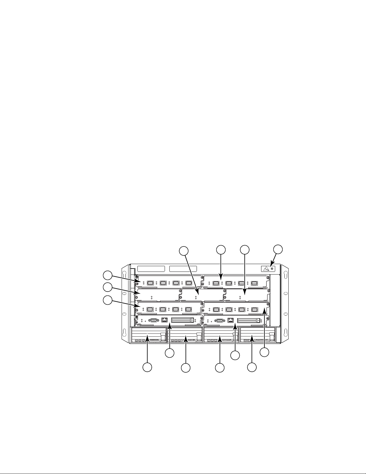
Figure 1 displays the Brocade MLXe-4 router.
FIGURE 1 Brocade MLXe-4 router
2 Brocade MLX Series and Brocade NetIron XMR Hardware Installation Guide
1 Interface slot 2 4 ESD connector 7 Interface slot 3 10 Interface slot 4
2 Switch fabric slot 2 5 Interface slot 1 8 Management slot 1 11-14 Power supplies
3 Switch fabric slot 3 6 Switch fabric slot 1 9 Management slot 2
53-1002373-02
Page 21
Hardware features
14 15
16
17
1 2
8
10
12
6
3
9
7
5
4
11
18
13
1
Brocade MLXe-8 router components
You can install the following components in the router slots:
• Up to two management modules (one active and one redundant).
• Up to three switch fabric modules.
• Up to eight interface modules.
• Up to four power supplies (AC or DC).
For a detailed list of components that ships with each router, refer to Appendix A, “Brocade MLXe
Chassis bundles”.
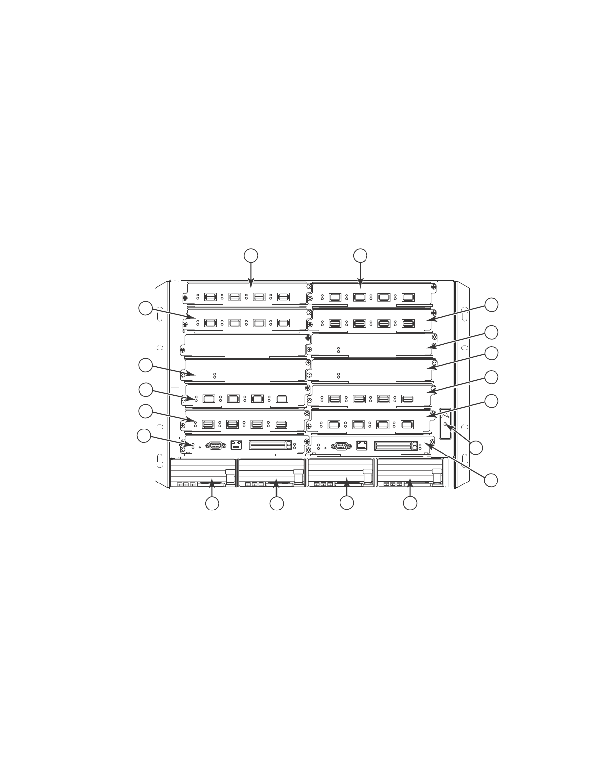
Figure 2 displays the Brocade MLXe-8 router.
FIGURE 2 Brocade MLXe-8 router
1 Interface slot 1 6 Switch fabric slot 2 11 Interface slot 8 16 Power supply slot 3
2 interface slot 2 7 Switch fabric slot 3 12 Management slot 1 17 Power supply slot 4
3 Interface slot 3 8 Interface slot 5 13 Management slot 2 18 ESD connector
4 Interface slot 4 9 Interface slot 6 14 Power supply slot 1
5 Switch fabric slot 1 10 Interface slot 7 15 Power supply slot 2
Brocade MLX Series and Brocade NetIron XMR Hardware Installation Guide 3
53-1002373-02
Page 22

Hardware features
1
Brocade MLXe-16 router components
You can install the following components in the router slots:
• Up to two management modules (one active and one redundant).
• Up to four switch fabric modules.
• Up to 16 interface modules.
• Up to eight power supplies (AC or DC).
For a detailed list of components that ships with each router, refer to Appendix A, “Brocade MLXe
Chassis bundles”.
4 Brocade MLX Series and Brocade NetIron XMR Hardware Installation Guide
53-1002373-02
Page 23
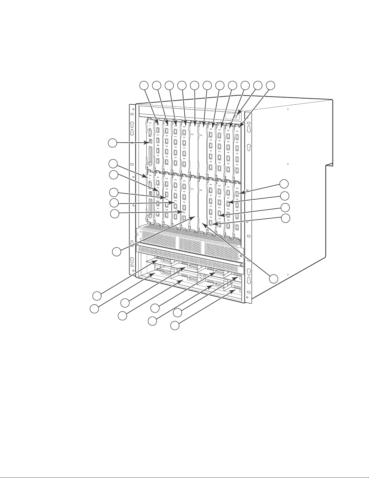
Figure 3 displays the Brocade MLXe-16 router.
12
13
14
15
16
17
18
19
20
21
22
23
1
2
3
4
5
6
7
8
91011
24
28
25
29
26
30
27
31
FIGURE 3 Brocade MLXe-16 router
Hardware features
1
1-16 Interface slots 1-16 20 Switch fabric slot 4 24-31 Power supplies
17 Switch fabric slot 1 21 Management slot 1
18 Switch fabric slot 2 22 Management slot 2
19 Switch fabric slot 3 23 ESD connector
Brocade MLX Series and Brocade NetIron XMR Hardware Installation Guide 5
53-1002373-02
Page 24

Hardware features
1
Brocade MLXe-32 router components
You can install the following components in the router slots:
• Up to two management modules.
• Up to eight switch fabric modules.
• Up to 32 interface modules.
• Up to eight power supplies (AC or DC).
For a detailed list of components that ships with each router, refer to Appendix A, “Brocade MLXe
Chassis bundles”.
6 Brocade MLX Series and Brocade NetIron XMR Hardware Installation Guide
53-1002373-02
Page 25
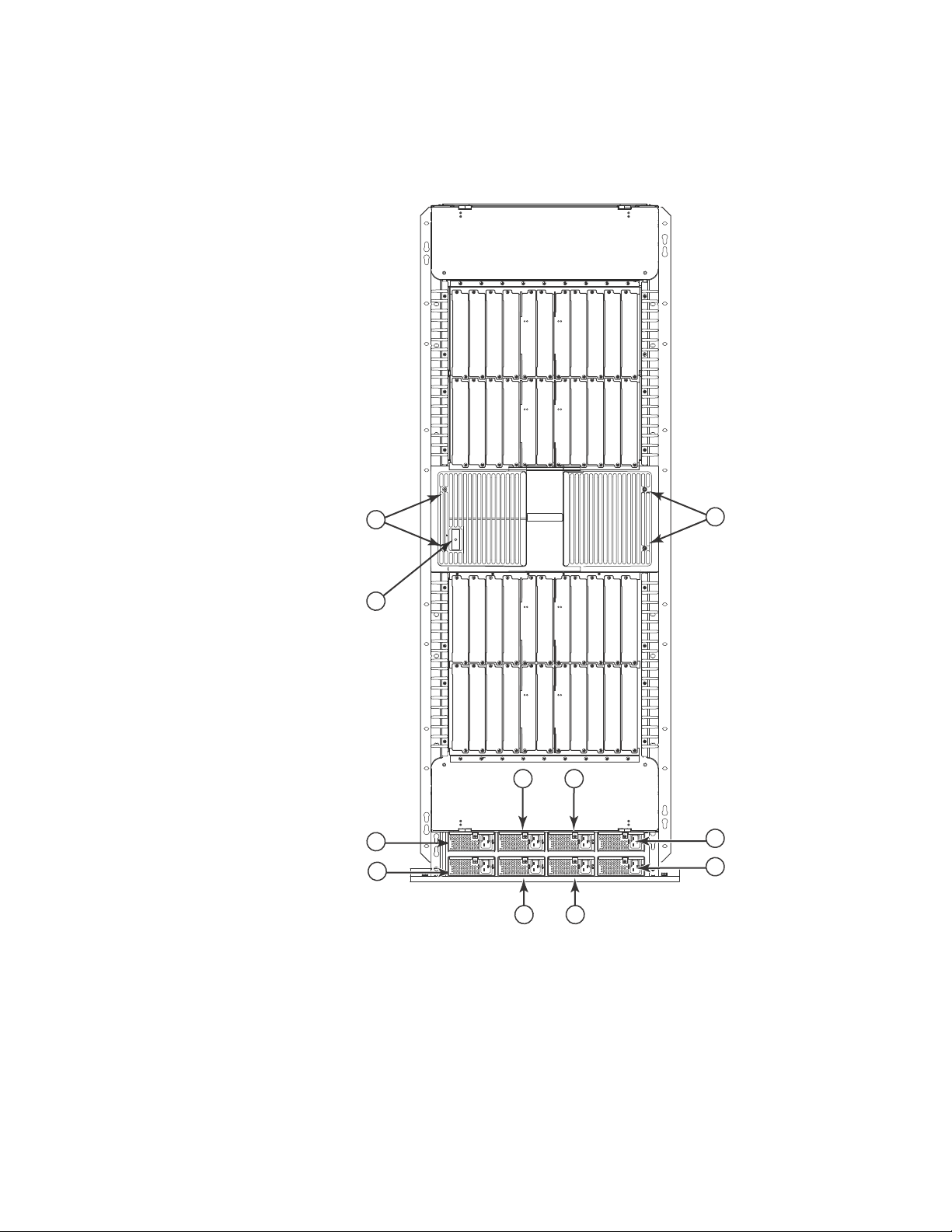
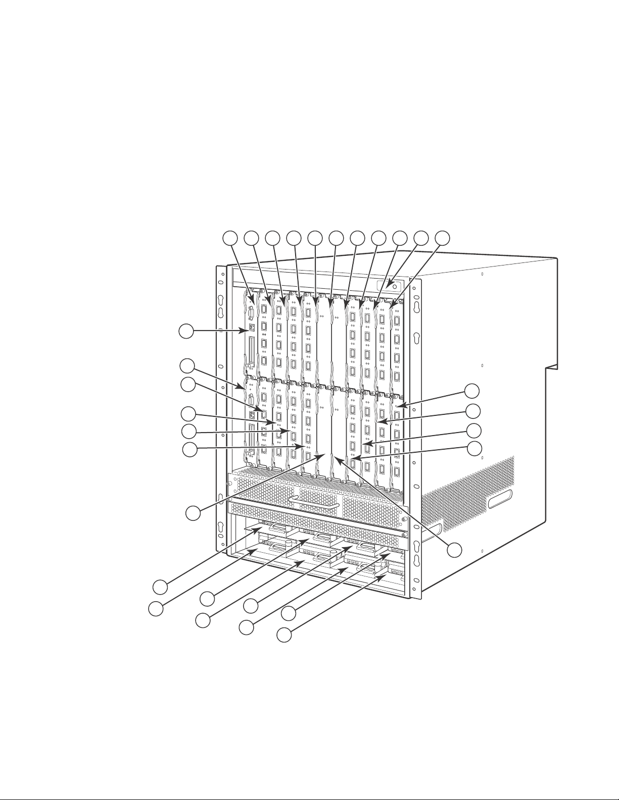
Figure 4 displays the Brocade MLXe-32 router.
44
45
43
43
Pwr
Active
Pwr
Active
Pwr
Active
Pwr
Active
357 91
2468 10
1133 35
34 36
41
12
13 15
14 16
Pwr
Active
Pwr
Active
Pwr
Active
Pwr
Active
17 19 21 23 37 39 25 27 29 31
18 20 22 24 38 42 40 26 28 30 32
46 47
49
50 51
AC OK
DC OK
ALM
AC OK
DC OK
ALM
AC OK
DC OK
ALM
AC OK
DC OK
ALM
AC OK
DC OK
ALM
AC OK
DC OK
ALM
AC OK
DC OK
ALM
AC OK
DC OK
ALM
52
48
FIGURE 4 Brocade MLXe-32 router
Hardware features
1
1-32 Interface slots 1-32 38 Switch fabric slot 6 44 ESD connector 50 Power supply 6
33 Switch fabric slot 1 39 Switch fabric slot 7 45 Power supply 1 51 Power supply 7
34 Switch fabric slot 2 40 Switch fabric slot 8 46 Power supply 2 52 Power supply 8
35 Switch fabric slot 3 41 Management slot 1 47 Power supply 3
36 Switch fabric slot 4 42 Management slot 2 48 Power supply 4
37 Switch fabric slot 5 43 Captive screws 49 Power supply 5
Brocade MLX Series and Brocade NetIron XMR Hardware Installation Guide 7
53-1002373-02
Page 26
Hardware features
7
6
5
1324
8910
11
12
13
1
Brocade MLX routers
Brocade MLX routers are available in the following models:
• Brocade MLX-4: 4 interface slots (see Figure 5 on page 8)
• Brocade MLX-8: 8 interface slots (see Figure 6 on page 9)
• Brocade MLX-16: 16 interface slots (see Figure 7 on page 10)
• Brocade MLX-32: 32 interface slots (see Figure 8 on page 12)
The following sections described the components you can install in the router slots.
Brocade MLX-4 router components
You can install the following components in the router slots:
• Up to two management modules (one active and one redundant).
• Up to three switch fabric modules.
• Up to four interface modules.
• Up to three power supplies (AC or DC).
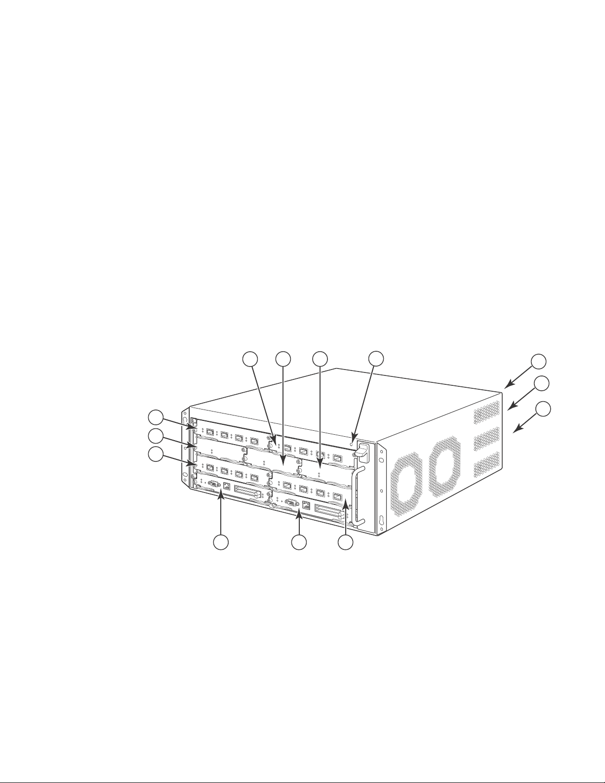
Figure 5 displays the Brocade MLX-4 router.
FIGURE 5 Brocade MLX-4 router
1 Interface slot 2 4 ESD connector 7 Interface slot 3 10 Interface slot 4
2 Switch fabric slot 2 5 Interface slot 1 8 Management slot 1 11 - 13 Three power supplies
3 Switch fabric slot 3 6 Switch fabric slot 1 9 Management slot 2
8 Brocade MLX Series and Brocade NetIron XMR Hardware Installation Guide
53-1002373-02
Page 27
Brocade MLX-8 router components
8
10
12
6
9
7
5
4
3
14 15
11
16 17
1 2
13
18
You can install the following components in the router slots:
• Up to two management modules (one active and one redundant).
• Up to three switch fabric modules.
• Up to eight interface modules.
• Up to four power supplies (AC or DC).
Figure 6 displays the Brocade MLX-8 router.
FIGURE 6 Brocade MLX-8 router
Hardware features
1
1 Interface slot 1 6 Switch fabric slot 2 11 Interface slot 8 16 Power supply slot 3
2 interface slot 2 7 Switch fabric slot 3 12 Management slot 1 17 Power supply slot 4
3 Interface slot 3 8 Interface slot 5 13 Management slot 2 18 ESD connector
4 Interface slot 4 9 Interface slot 6 14 Power supply slot 1
5 Switch fabric slot 1 10 Interface slot 7 15 Power supply slot 2
Brocade MLX Series and Brocade NetIron XMR Hardware Installation Guide 9
53-1002373-02
Page 28
Hardware features
12
13
14
15
16
17
18
19
20
21
22
23
1
2
3
4
5
6
7
8
91011
24
28
25
29
26
30
27
31
1
Brocade MLX-16 router components
You can install the following components in the router slots:
• Up to two management modules (one active and one redundant).
• Up to four switch fabric modules.
• Up to 16 interface modules.
• Up to eight power supplies (AC or DC).
Figure 7 displays the Brocade MLX-16 router.
FIGURE 7 Brocade MLX-16 router
1-16 Interface slots 1-16 20 Switch fabric slot 4 24-31 Power supplies
17 Switch fabric slot 1 21 Management slot 1
18 Switch fabric slot 2 22 Management slot 2
19 Switch fabric slot 3 23 ESD connector
10 Brocade MLX Series and Brocade NetIron XMR Hardware Installation Guide
53-1002373-02
Page 29

Brocade MLX-32 router components
You can install the following components in the router slots:
• Two management modules.
• Up to eight switch fabric modules.
• Up to 32 interface modules.
• Up to eight power supplies (AC or DC).
Hardware features
1
Brocade MLX Series and Brocade NetIron XMR Hardware Installation Guide 11
53-1002373-02
Page 30
Hardware features
Pwr
Active
Pwr
Active
Pwr
Active
Pwr
Active
Pwr
Active
Pwr
Active
Pwr
Active
Pwr
Active
AC OK
DC OK
ALM
AC OK
DC OK
ALM
AC OK
DC OK
ALM
AC OK
DC OK
ALM
AC OK
DC OK
ALM
AC OK
DC OK
ALM
AC OK
DC OK
ALM
AC OK
DC OK
ALM
357 91
2468 10
1133 35
34 36
41
12
13 15
14 16
17 19 21 23 37 39 25 27 29 31
18 20 22 24 38 42
43
44
45
43
40 26 28 30 32
46
47
48
52
49
50 51
1
Figure 8 displays the Brocade MLX-32 router.
FIGURE 8 Brocade MLX-32 router
1-32 Interface slots 1-32 38 Switch fabric slot 6 44 ESD connector 50 Power supply 6
33 Switch fabric slot 1 39 Switch fabric slot 7 45 Power supply 1 51 Power supply 7
34 Switch fabric slot 2 40 Switch fabric slot 8 46 Power supply 2 52 Power supply 8
35 Switch fabric slot 3 41 Management slot 1 47 Power supply 3
36 Switch fabric slot 4 42 Management slot 2 48 Power supply 4
37 Switch fabric slot 5 43 Captive screws 40 Power supply 5
12 Brocade MLX Series and Brocade NetIron XMR Hardware Installation Guide
53-1002373-02
Page 31

Hardware features
7
6
5
1324
8910
11
12
13
1
Brocade NetIron XMR routers
Brocade NetIron XMR Series routers are available in the following models:
• Brocade NetIron XMR 4000: 4 interface slots (see Figure 9 on page 13).
• Brocade NetIron XMR 8000: 8 interface slots (see Figure 10 on page 14).
• Brocade NetIron XMR 16000: 16 interface slots (see Figure 11 on page 15).
• Brocade NetIron XMR 32000: 32 interface slots (see Figure 12 on page 16).
The following sections described the components you can install in the router slots. For a detailed
list of components that ships with each router, refer to >>>>>>>>>>.
Brocade NetIron XMR 4000 router components
You can install the following components in the router slots:
• Up to two management modules (one active and one redundant).
• Up to three switch fabric modules.
• Up to four interface modules.
• Up to three power supplies (AC or DC).
Figure 9 displays the Brocade NetIron XMR 4000 router.
FIGURE 9 Brocade NetIron XMR 4000 router
1 Interface slot 2 4 ESD connector 7 Interface slot 3 10 Interface slot 4
2 Switch fabric slot 2 5 Interface slot 1 8 Management slot 1 11 -13 Three power supplies
3 Switch fabric slot 3 6 Switch fabric slot 1 9 Management slot 2
installed in rear of
device
Brocade MLX Series and Brocade NetIron XMR Hardware Installation Guide 13
53-1002373-02
Page 32

Hardware features
8
10
12
6
9
7
5
4
3
14 15
11
16 17
1 2
13
18
1
Brocade NetIron XMR 8000 router components
You can install the following components in the router slots:
• Up to two management modules (one active and one redundant).
• Up to three switch fabric modules.
• Up to eight interface modules.
• Up to four power supplies (AC or DC).
Figure 10 displays the Brocade NetIron XMR 8000 router.
FIGURE 10 Brocade NetIron XMR 8000 router
1 Interface slot 1 6 Switch fabric slot 2 11 Interface slot 8 16 Power supply slot 3
2 interface slot 2 7 Switch fabric slot 3 12 Management slot 1 17 Power supply slot 4
3 Interface slot 3 8 Interface slot 5 13 Management slot 2 18 ESD connector
4 Interface slot 4 9 Interface slot 6 14 Power supply slot 1
5 Switch fabric slot 1 10 Interface slot 7 15 Power supply slot 2
14 Brocade MLX Series and Brocade NetIron XMR Hardware Installation Guide
53-1002373-02
Page 33

Brocade NetIron XMR 16000 router components
12
13
14
15
16
17
18
19
20
21
22
23
1
2
3
4
5
6
7
8
91011
24
28
25
29
26
30
27
31
You can install the following components in the router slots:
• Up to two management modules (one active and one redundant).
• Up to four switch fabric modules.
• Up to 16 interface modules.
• Up to eight power supplies (AC or DC)
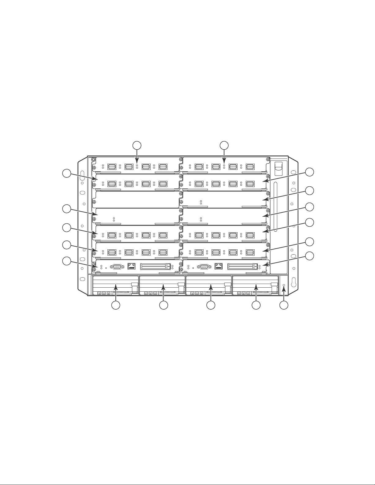
Figure 11 displays the Brocade NetIron XMR 16000 router.
FIGURE 11 Brocade NetIron XMR 16000 router
Hardware features
1
1-16 Interface slots 1-16 20 Switch fabric slot 4 24-31 Power supplies
17 Switch fabric slot 1 21 Management slot 1
18 Switch fabric slot 2 22 Management slot 2
19 Switch fabric slot 3 23 ESD connector
Brocade MLX Series and Brocade NetIron XMR Hardware Installation Guide 15
53-1002373-02
Page 34

Hardware features
44
45
43
43
Pwr
Active
Pwr
Active
Pwr
Active
Pwr
Active
357 91
2468 10
1133 35
34 36
41
12
13 15
14 16
Pwr
Active
Pwr
Active
Pwr
Active
Pwr
Active
17 19 21 23 37 39 25 27 29 31
18 20 22 24 38 42 40 26 28 30 32
46 47
49
50 51
AC OK
DC OK
ALM
AC OK
DC OK
ALM
AC OK
DC OK
ALM
AC OK
DC OK
ALM
AC OK
DC OK
ALM
AC OK
DC OK
ALM
AC OK
DC OK
ALM
AC OK
DC OK
ALM
52
48
1
Brocade NetIron XMR 32000 router components
You can install the following components in the router slots:
• Up to two management modules (one active and one redundant).
• Up to eight switch fabric modules.
• Up to 32 interface modules.
• Up to eight power supplies (AC or DC).
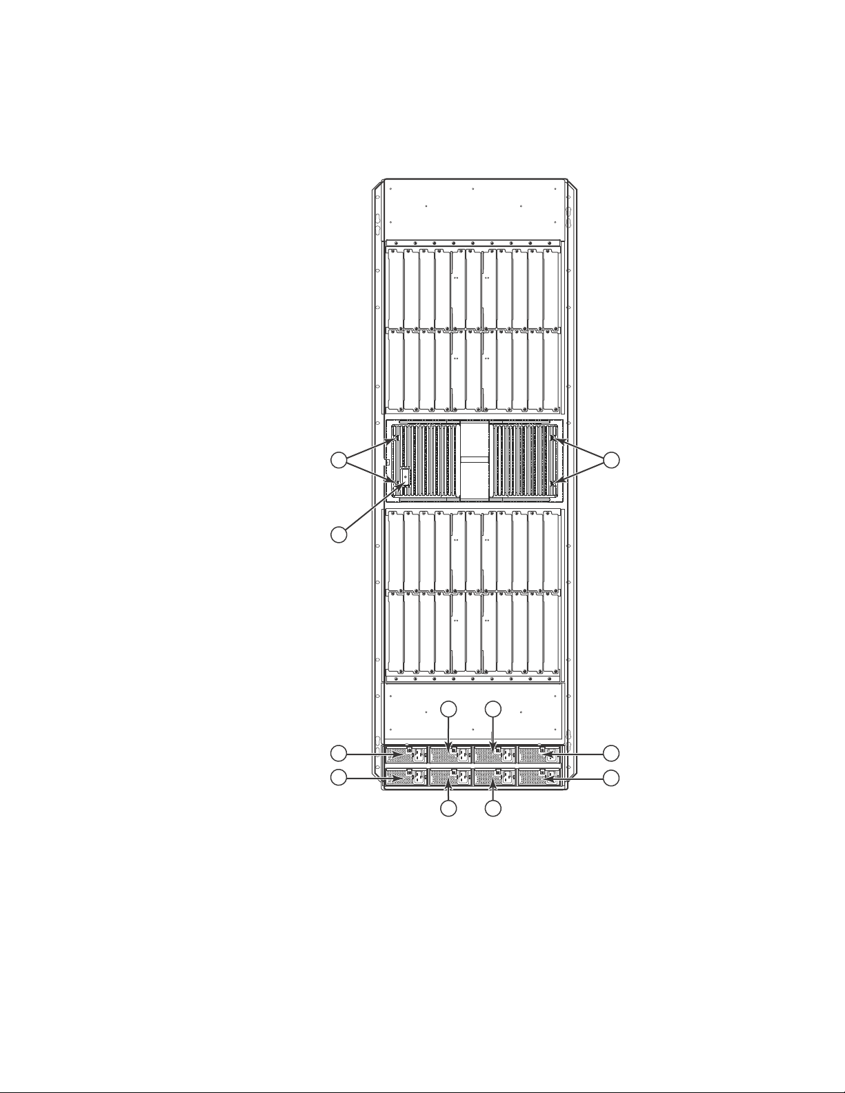
Figure 12 displays the Brocade NetIron XMR 32000 router.
FIGURE 12 Brocade NetIron XMR 32000 router
r
16 Brocade MLX Series and Brocade NetIron XMR Hardware Installation Guide
53-1002373-02
Page 35

1-32 Interface slots 1-32 38 Switch fabric slot 6 44 ESD connector 50 Power supply 6
33 Switch fabric slot 1 39 Switch fabric slot 7 45 Power supply 1 51 Power supply 7
34 Switch fabric slot 2 40 Switch fabric slot 8 46 Power supply 2 52 Power supply 8
35 Switch fabric slot 3 41 Management slot 1 47 Power supply 3
36 Switch fabric slot 4 42 Management slot 2 48 Power supply 4
37 Switch fabric slot 5 43 Captive screws 49 Power supply 5
Router modules
This section describes management modules, interface modules, and switch fabric modules.
Management modules
Brocade MLX, Brocade MLXe, and Brocade NetIron XMR routers support the following management
modules types:
• MR management module
• MR2 management module
Router modules
1
Tab le 1 lists the management modules available for Brocade MLXe, Brocade MLX, and Brocade
NetIron XMR routers.
TABLE 1 Management modules for all Brocade MLX Series and Brocade NetIron XMR routers
Part number Description
NI-MLX-MR (MR)
Brocade MLXe and Brocade MLX management module, 1 GB SDRAM, dual auxiliary flash
slots, EIA or TIA-232 and 10/100/1000 Ethernet ports for out-of-band management.
NI-MLX-32-MR (MR)
Brocade MLXe-32 and Brocade MLX-32 management module, 1 GB SDRAM, dual auxiliary
flash slots, EIA or TIA-232 and 10/100/1000 Ethernet ports for out-of-band management.
NI-XMR-MR
NI-XMR-32-MR
BR-MLX-MR2-M (MR2)
BR-MLX-MR2-X (MR2)
(MR)
Brocade NetIron XMR management module, 2 GB SDRAM, dual auxiliary flash slots, EIA or
TIA-232 and 10/100/1000 Ethernet ports for out-of-band management.
(MR)
Brocade NetIron XMR 32000 management module, 2 GB SDRAM, dual auxiliary flash slots,
EIA or TIA-232 and 10/100/1000 Ethernet ports for out-of-band management.
MLXe/MLX Gen2 management (M) module for 4-, 8- and 16-slot systems. Includes 4 GB
RAM, 1 internal compact flash drive (2GB), 1 external compact flash slot with included 2GB
card, RS-232 serial console port and 10/100/1000 Ethernet port for management.
MLXe/XMR Gen2 management (X) module for 4-, 8- and 16-slot systems. Includes 4 GB
RAM, 1 internal compact flash drive (2GB), 1 external compact flash slot with included 2GB
card, RS-232 serial console port and 10/100/1000 Ethernet port for management.
Brocade MLX Series and Brocade NetIron XMR Hardware Installation Guide 17
53-1002373-02
Page 36

Router modules
NOTE
NOTE
NOTE
Pwr
Active
10/100/1000
Port 1
Port 2
Console
RX-BI-MR
1
TABLE 1 Management modules for all Brocade MLX Series and Brocade NetIron XMR routers (Continued)
Part number Description
BR-MLX-32-MR2-M
BR-MLX-32-MR2-X
(MR2)
MLXe/MLX Gen2 management (M) module for 32-slot systems. Includes 4 GB RAM, 1
internal compact flash drive (2GB), 1 external compact flash slot with included 2GB card,
RS-232 serial console port and 10/100/1000 Ethernet port for management.
(MR2)
MLXe/XMR Gen2 management (X) module for 32-slot systems. Includes 4 GB RAM, 1
internal compact flash drive (2GB), 1 external compact flash slot with included 2GB card,
RS-232 serial console port and 10/100/1000 Ethernet port for management.
The management module controls the hardware components, runs the networking protocols, and
provides the Real Time Operating System (RTOS).
Each router requires one management module, and can accommodate a second module for
redundancy. A redundant management module works in conjunction with the active management
module. If the active module becomes unavailable, the redundant management module
automatically takes over the system operation, minimizing system downtime. For information about
the redundancy feature, refer to the “Using a Redundant Management Module” chapter in the
Brocade MLX Series and Brocade NetIron Family Configuration Guide.
Management modules are installed in dedicated slots marked M1 and M2. By default, the module
installed in slot M1 is the active management module.
Management modules are hot-swappable, which means you can remove and replace them without
powering down the system.
MR and MR2 management modules cannot be mixed in the same chassis.
Prior to installing or replacing the MR2 management module, you must read the Hardware
Installation Notes that shipped with the hardware.
Although management modules are designed to be hot-swappable, you must upgrade the software
on all interface modules and management modules to the appropriate software release before
installing them. For more information on the appropriate software release, refer to the Hardware
Installation Notes that shipped with the management module.
Figure 13 shows a management module front panel.
FIGURE 13 MR management module front panel
18 Brocade MLX Series and Brocade NetIron XMR Hardware Installation Guide
53-1002373-02
Page 37

Router modules
NOTE
NOTE
Figure 14 shows the MR2 management module front panel.
FIGURE 14 MR2 management module front panel
The front panel of the management module contains the following control features:
• Two auxiliary flash slots (available on MR management modules only)
• Compact flash slot (available on MR2 management modules only)
• Console port
• A 10/100/1000 Ethernet port
• Six LEDs
Auxiliary flash slots
1
Auxiliary flash slots support flash PC cards where you can store boot images, startup and running
configuration files, and other system files, in addition to what is stored in system flash memory.
This allows you to perform system management tasks, such as copying files between flash PC
cards, or copying files between a flash PC card and flash memory.
For maximum performance, it is recommended that you use Brocade auxiliary flash cards, part
number FLASH-PCC, which can be ordered from Brocade. Brocade auxiliary flash cards ship with
the label on the bottom of the card; take caution to insert the card with the label on the bottom
side.
Some older auxiliary flash cards can be inserted the wrong way in the slot because there is no
indication in the card about which is the right way. If you insert the card backwards, you will see
continuous messages in the console and the card inserted/ card removed syslog. If this occurs, you
must remove the card and reinsert it the correct way.
External compact flash
MR2 management modules do not contain an auxiliary flash slot. Instead, they contain a 2 GB
internal compact flash card and an external compact flash drive. MR2 management modules come
with a factory installed compact flash card in the external compact flash slot. The internal compact
flash provides greater storage space for image retention, improving the upgrade process.
Do not use compact flash cards over 2GB; they will render the system unstable.
The internal compact flash card cannot be accessed for removal or replacement.
The external compact flash slot allows you to insert a 2 GB compact flash card. If you need to
replace or add an additional compact flash card, contact Brocade technical support.
Brocade MLX Series and Brocade NetIron XMR Hardware Installation Guide 19
53-1002373-02
Page 38

Router modules
NOTE
NOTE
1
Console port
The console port is a standard DB-9 serial connector through which you can attach a PC or terminal
to configure the router using the CLI.
The console port interfaces the control plane only. It does not interface the data plane.
10/100/1000 Ethernet port
Management modules also contain a 10BaseT, 100BaseTX, or 1000BaseTX auto-sensing,
auto-negotiating Ethernet port. This port has an RJ45 unshielded twisted pair (UTP) connector.
Typical uses of this port include, but are not limited to, the following:
• Connecting a PC to configure, monitor, and manage the system through a Telnet or SSHv2
connection.
• Connecting to the 10BaseT, 100BaseTX, or 1000BaseTX port for connectivity to your existing
management network. You can then access the router and configure, monitor, and manage the
system from a management station.
The existing management network into which you can connect the 10/100/1000 Ethernet port
must be separate and isolated from the network over which user packets are switched and routed.
For information about the functionality of the management port, refer to “Understanding
management port functions” on page 317.
For information about connecting a PC to the 10/100/1000 Ethernet port, refer to “Attaching a
management station” on page 227.
Unlike the 10 Gbps Ethernet ports, the out-of-band port does not interface the LAN. Instead, the
out-of-band port can interface with a separate system management network, and allows you to do
the following tasks:
• Access the router through Telnet, the Web management interface, or the IronView Network
Manager software.
• Access a TFTP server to perform system upgrade tasks.
• Access SNMP messages or protocol data units (PDUs).
• Send Syslog packets.
• Access the system through RADIUS AAA.
20 Brocade MLX Series and Brocade NetIron XMR Hardware Installation Guide
53-1002373-02
Page 39

Router modules
Management module LEDs
The LEDs on all management module models are the same. Table 2 describes the LEDs on the
management module.
TABLE 2 Management module LEDs
LED Position State Meaning
1
Port 1
and
Port 2
Active Lower Left On The module is functioning as the active
Pwr Upper Left On The module is receiving power.
10/100/1000
Ethernet Port
10/100/1000
Ethernet Port
Each adjacent to
the auxiliary flash
slot that it
represents
Above and right of
RJ45 connector
Above and left of
RJ45 connector
On or blinking The software is currently accessing the auxiliary
flash card.
Off The software is not currently accessing a auxiliary
flash card, although there is one inserted in the slot.
management module.
Off The module is functioning as the redundant
management module.
Off The module is not receiving power.
On (Green) A link is established with the remote port.
Off No link is established with the remote port.
On or blinking
(Yellow)
Off for an
extended period
The port is transmitting and receiving packets.
The port is not transmitting or receiving packets.
Brocade MLX Series and Brocade NetIron XMR Hardware Installation Guide 21
53-1002373-02
Page 40

Router modules
1
Interface modules
Interface modules for Brocade MLX, Brocade MLXe, and Brocade NetIron XMR routers are available
in two types:
• Gen-1 interface modules
• Gen-2 interface modules, which provide additional functionality, more memory, and higher
operation speeds.
Tab le 3 lists the interface modules that are available for Brocade MLX Series and Brocade NetIron
XMR routers.
TABLE 3 Interface modules for all Brocade MLX Series and Brocade NetIron XMR routers
SKU Ports Supported on Description
NI-MLX-10GX2 2 MLXe, MLX NetIron MLX Series 2-port 10-GbE module with
IPv4/IPv6/MPLS hardware support - requires XFP optics
NI-XMR-10GX2 2 XMR (no longer
available)
NI-X-OC192-1 2 MLXe, MLX, XMR (no
longer available)
NI-X-OC48X2 2 MLXe, MLX, XMR NetIron XMR/MLX 2-port OC-12/48 (STM-4/16) Packet
BR-MLX-100GX-1 1 MLXe, MLX, XMR MLXE/XMR/MLX 1-port 100-GbE (X) Module with
BR-MLX-100GX-2 2 MLXe, MLX MLXE 2-port 100-GbE (X) Module with IPv4/IPv6/MPLS
NI-MLX-10GX4 4 MLXe, MLX NetIron MLX Series 4-port 10-GbE module with
NI-XMR-10Gx4 4 XMR NetIron XMR Series 4-port 10-GbE module with
NI-X-OC48X4 4 MLXe, MLX, XMR NetIron XMR/MLX 4-port OC-12/48 (STM-4/16) Packet
BR-MLX-10GX4-X 4 MLXe, MLX, XMR XMR/MLXe 4-port 10-GbE (X) module with
BR-MLX-10Gx4-X-ML 4 MLXe, MLX, XMR MLX/MLXe 4-port 10-GbE (ML) module with
Gen-1 2-port 10-Gbps Ethernet module - requires XFP
optics. IPv4, IPv6, MPLS support
Gen-1 2-port OC-192 POS/SDH module. IPv4, IPv6,
MPLS support. Requires SFP optics.
over SONET/SDH module interface module with
IPv4/IPv6/MPLS hardware support. Requires SFP
optics.
IPv4/IPv6/MPLS hardware support - requires CFP
optics. Supports 1M IPv4 routes in FIB in XMR mode and
512K IPv4 routes in MLX mode. Requires high speed
switch fabric modules. License upgradable to 2-ports on
a MLXe.
hardware support - requires CFP optics. Supports 1M
IPv4 routes in FIB in XMR mode and 512K IPv4 routes in
MLX mode. Requires high speed switch fabric modules.
IPv4/IPv6/MPLS hardware support - requires XFP optics
IPv4/IPv6/MPLS hardware support - requires XFP optics
over SONET/SDH module interface module with
IPv4/IPv6/MPLS hardware support. Requires SFP
optics.
IPv4/IPv6/MPLS hardware support - requires XFP optics.
Supports 1M IPv4 routes in FIB.
IPv4/IPv6/MPLS hardware support-requires XFP optics.
Supports 512K IPv4 routes in FIB. License Upgradable
to "X" scalability (1M IPv4 routes in FIB).
22 Brocade MLX Series and Brocade NetIron XMR Hardware Installation Guide
53-1002373-02
Page 41

Router modules
TABLE 3 Interface modules for all Brocade MLX Series and Brocade NetIron XMR routers (Continued)
SKU Ports Supported on Description
NI-X-OC48X8 8 MLXe, MLX, XMR NetIron XMR/MLX 8-port OC-12/48 (STM-4/16) Packet
over SONET/SDH module interface module with
IPv4/IPv6/MPLS hardware support. Requires SFP
optics.
NI-MLX-10GX8-M 8 MLXe, MLX Brocade MLX Series 8-port 10-GbE (M) module with
IPv4/IPv6/MPLS hardware support - requires SFPP
optics. Supports 512K IPv4 routes in FIB. Requires high
speed switch fabric modules
NI-MLX-10GX8-D 8 MLXe, MLX Brocade MLX Series 8-port 10-GbE (D) module with
IPv4/IPv6 hardware support - requires SFPP optics.
Supports 256K IPv4 routes in FIB. Doesn't support
MPLS. Requires high speed switch fabric modules
BR-MLX-10GX8-X 8 MLXe, MLX, XMR MLXe/XMR 8-port 10-GbE (X) module with
IPv4/IPv6/MPLS hardware support-requires SFPP
optics. Supports 1M IPv4 routes in FIB. Requires high
speed switch fabric modules.
NI-MLX-1GX20-SFP 20 MLXe, MLX NetIron MLX Series 20-port FE/GE (100/1000) module
with IPv4/IPv6/MPLS hardware support - requires SFP
optics. Note: Copper SFPs are supported at 1000Mbps
only
NI-XMR-1GX20-SFP 20 XMR NetIron XMR Series 20-port FE/GE (100/1000) module
with IPv4/IPv6/MPLS hardware support - requires SFP
optics. Note: Copper SFPs are supported at 1000Mbps
only
NI-MLX-1GX20-GC 20 MLXe, MLX NetIron MLX Series 20-port 10/100/1000 copper
module with IPv4/IPv6/MPLS hardware support
NI-XMR-1Gx20-GC 20 XMR NetIron XMR Series 20-port 10/100/1000 copper
module with IPv4/IPv6/MPLS hardware support
BR-MLX-1GCX24-X 24 MLXe, MLX, XMR XMR/MLXE 24-port 1-GbE (X) Copper (RJ-45) Module.
Supports 1M IPv4 routes in FIB.
BR-MLX-1GCX24-X-ML 24 MLXe, MLX, XMR MLX/MLXE 24-port 1-GbE (ML) Copper (RJ-45) Module.
Supports 512K IPv4 routes in FIB. License Upgradable
to “X” scalability (1M IPv4 routes in FIB).
BR-MLX-1GFx24-X 24 MLXe, MLX, XMR XMR/MLXE 24-port 1-GbE (X) Copper (RJ-45) Module.
Supports 1M IPv4 routes in FIB.
BR-MLX-1GFX24-X-ML 24 MLXe, MLX, XMR MLX/MLXE 24-port 1-GbE (ML) Fiber (SFP) Module.
Supports 512K IPv4 routes in FIB. License Upgradable
to “X” scalability (1M IPv4 routes in FIB).
NI-MLX-1GX48-T-A 48 MLXe, MLX NetIron MLX Series 48-port 10/100/1000Base-T,
MRJ21 module with IPv4/IPv6/MPLS hardware support.
Requires high speed fans NIBI-16-FAN-EXH-A on MLX-16.
1
Depending on your router model, you can install up to 32 single-slot interface modules, or 16
double-slot interface modules.
Interface modules are hot-swappable, which means you can remove and replace them without
powering down the system.
Brocade MLX Series and Brocade NetIron XMR Hardware Installation Guide 23
53-1002373-02
Page 42

Router modules
NOTE
NOTE
1
Tab le 4provides a compatibility matrix for MLXe modules.
TABLE 4 Brocade MLXe module compatibility matrix
Module MLX XMR MLXe with MLX
or MR2-M mgmt
module
MLX 4x10G Yes No Yes No G1 SFM, hSFM
MLX 2x10G Yes No Yes No G1 SFM, hSFM
MLX 20x1G Yes No Yes No G1 SFM, hSFM
MLX
48x1G-T
MLX
8x10G-D
MLX
8x10G-M
XMR 4x10G No Yes No Yes G1 SFM, hSFM
XMR 20x1G No Yes No Yes G1 SFM, hSFM
POS Yes Yes Yes Yes G1 SFM, hSFM
24x1G-X Yes Yes++ Yes Yes++ G1 SFM, hSFM
4x10G-X Yes Yes++ Yes Yes++ G1 SFM, hSFM
8x10G-X Yes Yes Yes Yes G2 hSFM
100G Yes Yes Yes Yes G2 h SFM
SFMYesYesNoNoG1N/A
hS FM Yes Ye s Yes Ye s G2 N /A
Yes No Ye s No G1 SFM, hSFM
Yes No Ye s No G2 h SFM
Yes No Ye s No G2 h SFM
MLXe with XMR
or MR2-X mgmt
module
Generation
(G)
Fabric
Compatibility
++ Requires “X” scalability requirement
100xGbE 2-port interface module
The 100xGbE 2-port interface module is supported on all Brocade MLX Series and Brocade NetIron
XMR routers. This interface module has two 100 Gbps CFP optics ports, 2 Gbps memory, an
internal flash of 32MB for local storage of CPU images, and 64MB for local storage of FPGA
images. The 100xGbE 2-port interface module supports 1.5 MB buffering per port.
Only Brocade MLXe devices support both ports on the 100xGbE module. Brocade MLX and Brocade
NetIron XMR models support one port only.
The 100xGbE interface module occupies two interface module slots in any chassis, with one slot
active and one slot inactive. In all devices, the lower number of the two occupied slots becomes the
active slot.
Because of the possibility of overheating, 2x100GbE interface modules should not be installed in
the top slot of a Brocade MLX 4-slot chassis.
24 Brocade MLX Series and Brocade NetIron XMR Hardware Installation Guide
53-1002373-02
Page 43

Router modules
NOTE
NOTE
NOTE
Pwr Lnk/Act
1
2
Lnk/Act
1
Before you install a 2x100GbE module, you will need to remove the center slot guide that divides
the slot into two partitions. Do not discard this guide, as you will need it if you ever want to convert
the slot into two slots. For information about how to remove the center guide and install high-speed
fabric modules, refer to the 2x100GbE module installation instructions in the appropriate
installation chapter for your router model.
Before installing the 100GbE module in a chassis, the tm-credit-size must be changed to 1024
bytes.
You will also need to change the system tm credit size to 1024b (which readies the device to
forward 100 Gbps traffic). Log into your system and enter the following commands in the
configuration level of the CLI. Remember to write to memory and reload the device.
Brocade# config
Brocade(config)# system-init tm-credit-size credit_1024b
Brocade(config)# exit
Brocade# write memory
Brocade# reload
The 100GbE module requires a minimum software version of R05.2.00. Please upgrade all software
on the system to a minimum version of R05.2.00 before you inst all your 2x100G module.
100xGbE modules require high-speed switch fabric modules to operate.
Figure 15 shows the front panel of the 2x100GbE 2-port interface module.
FIGURE 15 100xGbE 2-port interface module front panel
The front panel contains the following features:
• Power LED and Lnk/Act LED for each port (as described in Table 5)
• Two 100xGbE CF P p or ts
100xGbE interface module LEDs
The LEDs on the 100xGbE interface modules indicate the status of each port, as described in
Tab le 5.
TABLE 5 100xGbE module LEDs
LED Location State Meaning
Power (module state) Left side of module Green Module is receiving power
Off Module is not receiving power
Link/Act To the right of each port. Green blinking Port is enabled and link is up.
Off Port is disabled.
Brocade MLX Series and Brocade NetIron XMR Hardware Installation Guide 25
53-1002373-02
Page 44

Router modules
1
CFP optics
The 100 GbE interface module is 802.3ba compliant, supports CFP-based optics, and is
backwards-compatible with existing Brocade MLX and Brocade NetIron XMR interface modules.
This interface module requires high-speed fabric modules. 100GbE interface modules will boot in
turbo mode if all modules in the chassis are Gen-2 modules.
You must insert CFP-compliant fiber-optic transceivers in each port you intend to use.
CFP-compliant transceivers provide an optical or physical medium-dependent (PMD) interface for
single- or multi-mode fiber that can be used with either the LAN physical layer (PHY) or WAN
physical layer (WAN PHY).
For a list of supported 100xGbE CFP-compliant fiber-optic transceivers that are available from
Brocade, refer to the latest version of the Brocade Optics Family Data Sheet, available online in the
following location:
http://www.brocade.com/downloads/documents/data_sheets/product_data_sheets/Optics_DS.p
df
For more information about fiber-optic transceivers and associated cabling, refer to “Installing a
fiber-optic transceiver” on page 318.
Power supply requirements for 100xGbE modules
Tab le 6 lists the power supply requirements for each type of router when installing 100xGbE
modules.
TABLE 6 Power supply requirements for 100xGbE modules
Router type Number of 100xGbE
modules installed
MLXe-4 one one 1200W PSU
two two 1200W PSU
MLX-4 and
Brocade NetIron
XMR 4000
MLXe-8 two two 1200W PSU
Brocade NetIron
XMR 8000
two (1x100GE) one 1200W PSU
three or four three 1200W PSU
four (1x100GE) two 1200W PSU
Power supply requirements (minimum required-redundancy requirements)
for 1+1 redundancy, install two 1200W PSU
one 1800W PSU
for 1+1 redundancy, install two 1800W PSU
for 2+1 redundancy, install three 1200W PSU
one 1800W PSU
for 1+1 redundancy, install two 1800W PSU
for 1+1 redundancy, install two 1200W PSU
for 1+1 redundancy, install four 1200W PSU
one 1800W PSU
for 1+1 redundancy, install two 1800W PSU
for 3+1 redundancy, install four 1200W PSU
two 1800W PSU
for 2+2 redundancy, install four 1800Q PSU
for 2+2 redundancy, install four 1200W
26 Brocade MLX Series and Brocade NetIron XMR Hardware Installation Guide
53-1002373-02
Page 45

NOTE
TABLE 6 Power supply requirements for 100xGbE modules (Continued)
1
2
7
8
Router type Number of 100xGbE
modules installed
MLXe-16 six four 1200W PSU
seven to eight a minimum of five 1200W PSU
Brocade NetIron
XMR 1600
MLXe-32 twelve four 2400W PSU
Brocade NetIron
XMR 3200
eight (1x100GE) four 1200W PSU
thirteen to sixteen five 2400W PSU
sixteen (1x100GE) four 2400W PSU
Power supply requirements (minimum required-redundancy requirements)
for 4+4 redundancy, install eight 1200W PSU
for 3+3 redundancy, install four 1800W PSU
for 4+4 redundancy, install eight 1800W PSU
for 5+3 redundancy, install eight 1200W PSU
for 4+4 redundancy, install eight 1200W PSU
for 4+4 redundancy, install eight 2400W PSU
for 5+3 redundancy, install eight 2400W PSU
four 3000W PSU
for 4x4 redundancy, instal eight 3000W PSU
for 4+4 redundancy, install eight 2400W PSU
Router modules
1
8x10GE-X interface modules
The 8x10GE-X interface modules provide 8 ports of 10 Gigabit Ethernet with support for 1M IPv4
routes in hardware.
Gen-2 8x10GE-X modules require high speed switch fabric modules to operate. You can replace
switch fabric modules with high-speed switch fabric modules while the system is powered on and
running. For more information about high-speed switch fabric modules, refer to “High-speed switch
fabric modules” on page 50.
Figure 16 shows the faceplate of the 8x10GE-X module.
FIGURE 16 8x10GE-X module faceplate
8x10GE-X modules support SFP+ optics only; they do not support SFP or CFP optics. For a list of
supported SFP+ optics, refer to the latest version of the Brocade Optics Family Data Sheet,
available online in the following location:
http://www.brocade.com/downloads/documents/data_sheets/product_data_sheets/Optics_DS.p
df
Brocade MLX Series and Brocade NetIron XMR Hardware Installation Guide 27
53-1002373-02
Page 46

Router modules
1
8x10GE-X interface module LEDs
The 8x10GE-X interface module LEDs indicate module and port status, as described in Tab le 7.
TABLE 7 8x10GE-X module LEDs
LED Location State Meaning
Power Lower left corner of module Green Module is receiving power
Off Module is not receiving power
Link/Act Below the ports. Top port
LED on left, bottom port LED
on right.
Green
blinking
Off Port is disabled.
Port enabled and link is passing traffic. LED is solid
green when link is idle.
Power supply requirements for 8x10GE-X modules
Tab le 8 lists the power supply requirements for each type of router when installing 8x10GE-X
modules.
TABLE 8 Power supply requirements for 8x10GE-X modules
Router type Number of 8x10GE-X
modules installed
Power supply requirements
MLXe-4 one one 1200W PSU
for 1+1 redundancy, install two 1200W PSU
two to four two 1200W PSU
for 2+2 redundancy, install four 1200W PSU
one 1800W PSU
for 1+1 redundancy, install two 1800W PSU
MLX-4 and
Brocade NetIron
XMR 4000
MLXe-8 and
Brocade NetIron
XMR 8000
All 16-slot routers fifteen four 1200W PSU
All 32-slot routers twenty-eight four 2400W PSU
four one 1200W PSU
for 1+1 redundancy, install two 1200W PSU
seven two 1200W PSU
for 2+2 redundancy, install four 1200W PSU
eight three 1200W PSU
for 3+1 redundancy, install four 1200W PSU
two 1800W PSU
for 2+3 redundancy, install four 1800W PSU
for 4+4 redundancy, install eight 1200W PSU
sixteen five 1200W PSU
for 5+3 redundancy, install eight 1200W PSU
four 1800W PSU
for 4+4 redundancy, install eight 1800W PSU
for 4+4 redundancy, install eight 2400W PSU
twenty-nine to
thirty-two
five 2400W PSU
for 4+4 redundancy, install eight 2400W PSU
four 3000W PSU
for 4+4 redundancy, install 3000W PSU
28 Brocade MLX Series and Brocade NetIron XMR Hardware Installation Guide
53-1002373-02
Page 47

Router modules
NOTE
Lnk
Active
Lnk
Active
Lnk
Active
Lnk
Active
1
2
34
Lnk
Active
Lnk
Active
1
2
1
Gen-1 10Gx2 and 10Gx4 Ethernet interface modules
Gen-1 2-port and 4-port 10 Gbps Ethernet interface modules are available in the following formats:
• NI-MLX-10Gx2 - 2-port interface module for MLX devices
• NI-XMR-10Gx2 - 2-port interface module for XMR devices
• NI-MLX-10Gx4 - 4-port interface module for MLX devices
• NI-XMR-10Gx4 - 4-port interface module for XMR devices
When you install Gen-1 2-port or 4-port 10 Gbps Ethernet interface modules, you must upgrade the
software on all interface modules and management modules to the appropriate software release.
For more information on the appropriate software release refer to the Hardware Installation Notes
that shipped with the interface module.
Figure 17 shows Gen-1 2-port and 4-port 10 Gbps Ethernet interface module front panels.
FIGURE 17 Gen-1 2-port and 4-port 10 Gbps Ethernet module front panels
The front panel of the 2-port module includes the following features:
• Two LEDs per port (as described in Table 9)
• Two 10 Gbps Ethernet XFP optics ports
The front panel of the 4-port module includes the following features:
• Two LEDs per port (as described in Table 9)
• Four 10 Gbps Ethernet XFP optics ports
10 Gbps Ethernet interface module LEDs
Gen-1 2-port and 4-port interface modules have LEDs that indicate the status of each port, as
described in Table 9.
TABLE 9 Gen-1 2-port or 4-port 10 Gbps Ethernet module LEDs
LED Location State Meaning
Link Left of each
Brocade MLX Series and Brocade NetIron XMR Hardware Installation Guide 29
53-1002373-02
Active Left of each
Ethernet port
Ethernet port
On A link is established with the remote port.
Off A link is not established with the remote port.
On The port is transmitting and receiving packets.
Off The port is not transmitting or receiving packets.
Page 48

Router modules
1
10 Gbps Ethernet ports
The Gen-1 2-port or 4-port Ethernet modules (BR-MLX-10Gx4-X) have either two or four physical
ports that allow you to connect your router to other network routers at a speed of 10 Gbps.
You must insert XFP-compliant fiber-optic transceivers in each port you intend to use.
XFP-compliant transceivers provide an optical or physical medium-dependent (PMD) interface for
single- or multi-mode fiber that can be used with either the LAN physical layer (PHY) or WAN
physical layer (WAN PHY).
For a list of XFP-compliant fiber-optic transceivers supported for Gen-1 2-port or 4-port modules,
refer to the latest version of the Brocade Optics Family Data Sheet, available online in the following
location:
http://www.brocade.com/downloads/documents/data_sheets/product_data_sheets/Optics_DS.p
df
For more information about fiber-optic transceivers and associated cabling, refer to “Installing a
fiber-optic transceiver” on page 318.
30 Brocade MLX Series and Brocade NetIron XMR Hardware Installation Guide
53-1002373-02
Page 49

Router modules
1
Power supply requirements for Gen-1 2-port or 4-port 10 Gbps Ethernet interface modules
Tab le 10 lists the power supply requirements for each type of router when installing Gen-1 2-port or
4-port 10 Gbps Ethernet interface modules.
TABLE 10 Power supply requirements for Gen-1 2-port or 4-port 10 Gbps Ethernet interface modules
Router type Number of Gen-1
2-port or 4-port Gbps
Ethernet interface
modules installed
MLXe-4 three one 1200W PSU
four two 1200W PSU
MLX-4 and
Brocade NetIron
XMR 4000
MLXe-8 seven two 1200W PSU
Brocade NetIron
XMR 8000
All 16-slot routers sixteen four 1200W PSU
All 32-slot routers thirty-two four 2400W PSU
four one 1200W PSU
eight three 1200W PSU
eight two 1200W PSU
Power supply requirements
for 1+1 redundancy, install two 1200W PSU
for 2+2 redundancy, install four 1200W PSU
for 1+1 redundancy, install two 1200W PSU
for 2+2 redundancy, install four 1200W PSU
for 3+1 redundancy, install four 1200W PSU
for 2+2 redundancy, install eight 1200W PSU
for 4+4 redundancy, install eight 1200W PSU
for 4+4 redundancy, install eight 2400W PSU
Brocade MLX Series and Brocade NetIron XMR Hardware Installation Guide 31
53-1002373-02
Page 50

Router modules
NOTE
Lnk
Active
Lnk
Active
Lnk
Active
Lnk
Active
1
2
34
1
Gen-2 4-port 10 Gbps Ethernet interface modules
Gen-2 4-port 10 Gbps Ethernet interface modules are available in the following formats:
• BR-MLX-10Gx4-X-ML - 4-port interface module for MLX and MLXe devices
• BR-MLX-10GX4-X - 4-port interface module for XMR and MLXe devices
The 10Gx4-X10 GbE module requires a minimum software version of R0.51.00. Please upgrade all
software on the system to a minimum of R05.1.00 before installing your 10Gx4-X module.
Figure 18 shows the front panel of 4-port 10 Gbps Ethernet interface modules.
FIGURE 18 BR-MLX-10Gx4-X and BR-MLX-10Gx4-X-ML interface module front panel
The front panel of the BR-MLX-10GX4-X and BR-MLX-10Gx4-X-ML modules includes the following
features:
• Two LEDs per port
• Four 10 Gbps Ethernet XFP optics ports
BR-MLX-10GX4-X and BR-MLX-10Gx4-X-ML interface module LEDs
The BR-MLX-10GX4-X and BR-MLX-10Gx4-X-ML interface module LEDs indicate the status of each
port, as described in Table 11.
TABLE 11 BR-MLX-10GX4-X and BR-MLX-10Gx4-X-ML Ethernet module LEDs
LED Location State Meaning
Link Left of each
Ethernet port
Active Left of each
Ethernet port
BR-MLX-10GX4-X and BR-MLX-10Gx4-X-ML interface module Ethernet ports
The BR-MLX-10GX4-X interface module has four physical ports that allow you to connect your router
to other network routers at a speed of 10 Gbps. BR-MLX-10Gx4-X-ML supports up to 512K IPv4
routes in hardware. BR-MLX-10Gx4-X supports up to 1M IPv4 routes. BR-MLX-10Gx4-X-ML can be
upgraded to an X version through a software license. Please contact Brocade to purchase the
license upgrade.
You must insert XFP-compliant fiber-optic transceivers in each port you intend to use.
XFP-compliant transceivers provide an optical or physical medium-dependent (PMD) interface for
single- or multi-mode fiber that can be used with either the LAN physical layer (PHY) or WAN
physical layer (WAN PHY).
On A link is established with the remote port.
Off A link is not established with the remote port.
On The port is transmitting and receiving packets.
Off The port is not transmitting or receiving packets.
32 Brocade MLX Series and Brocade NetIron XMR Hardware Installation Guide
53-1002373-02
Page 51

Router modules
1
For an up to date list of the 10 Gbps XFP-compliant fiber-optic transceivers that are available from
Brocade, refer to the latest version of the Brocade Optics Family Data Sheet, available online in the
following location:
http://www.brocade.com/downloads/documents/data_sheets/product_data_sheets/Optics_DS.p
df
For more information about fiber-optic transceivers and associated cabling, refer to “Installing a
fiber-optic transceiver” on page 318.
Power supply requirements for 10Gx4 interface modules
Tab le 12 lists the power supply requirements for each type of router when installing
BR-MLX-10GX4-X interface modules.
TABLE 12 Power supply requirements for BR-MLX-10GX4-X and BR-MLX-10Gx4-X-ML interface modules
Router type Number of Gen-2
10GX4-X interface
modules installed
MLXe-4 three one 1200W PSU
four two 1200W PSU
MLX-4 and
Brocade NetIron
XMR 4000
MLXe-8 seven two 1200W PSU
Brocade NetIron
XMR 8000
All 16-slot routers sixteen four 1200W PSU
All 32-slot routers thirty-two four 2400W PSU
four one 1200W PSU
eight three 1200W PSU
eight two 1200W PSU
Power supply requirements
for 1+1 redundancy, install two 1200W PSU
for 2+2 redundancy, install four 1200W PSU
for 1+1 redundancy, install two 1200W PSU
for 2+2 redundancy, install four 1200W PSU
for 3+1 redundancy, install four 1200W PSU
for 2+2 redundancy, install eight 1200W PSU
for 4+4 redundancy, install eight 1200W PSU
for 4+4 redundancy, install eight 2400W PSU
Brocade MLX Series and Brocade NetIron XMR Hardware Installation Guide 33
53-1002373-02
Page 52

Router modules
NOTE
NOTE
NOTE
NOTE
1
2
7
8
1
Gen-2 8-port 10 Gbps interface modules
For Brocade MLXe and Brocade MLX routers, the 8-port, 10 Gbps interface modules
(NI-MLX-10Gx8-M and NI-MLX-10Gx8-D) provide eight 10 Gbps ports that support SFP+ optics.
These modules contain an internal flash memory of 16 MB for local storage of CPU images, and 32
MB for local storage of FPGA images. The NI-MLX-10Gx8-M interface module supports a buffer of 3
GB buffering per module. The NI-MLX-10Gx8-D module supports 1 GB buffering per module.
NI-MLX-10Gx8-M and NI-MLX-10Gx8-D modules are designed for use with Brocade MLXe and
Brocade MLX routers only. They are not supported for Brocade NetIron XMR routers.
When installing NI-MLX-10Gx8-M or NI-MLX-10Gx8-D modules, you must first upgrade the software
on all interface modules and management modules to Multi-Service IronWare software R05.0.00 or
later. For more information, refer to the Hardware Installation Notes that shipped with the modules.
NI-MLX-10Gx8-D interface modules do not support MPLS.
NI-MLX-10Gx8-M or NI-MLX-10Gx8-D modules require high-speed switch fabric modules to operate.
You can replace switch fabric modules with high-speed switch fabric modules while the system is
powered on and running. For more information about high-speed switch fabric modules, see
“High-speed switch fabric modules” on page 50.
For Brocade MLX 16-slot routers, NI-MLX-10Gx8-M and NI-MLX-10Gx8-D modules require the
installation of high-speed fans in addition to high-speed switch fabric modules. For information
about the high-speed fans, see “NIBI-16-FAN-EXH-A high-speed fan assemblies” on page 61.
Figure 19 displays the faceplate of the NI-MLX-10Gx8-M and NI-MLX-10Gx8-D modules. Figure 20
shows the RX and TX orientation for the ports, and identifies which LED goes with which port.
FIGURE 19 NI-MLX-10Gx8-M and NI-MLX-10Gx8-D module faceplate
34 Brocade MLX Series and Brocade NetIron XMR Hardware Installation Guide
53-1002373-02
Page 53

Router modules
NOTE
1
2
7
8
1 TX RX
2 RX TX 4 RX TX 6 RX TX 8 RX TX
3 TX RX 5 TX RX 7 TX RX
LEDs 1 2 3 4 5 6 7 8
1
FIGURE 20 Port RX and TX, and LED designations for NI-MLX-10Gx8-M and NI-MLX-10Gx8-D modules
NI-MLX-10Gx8-M and NI-MLX-10Gx8-D modules support the SFP+ optics; they do not support SFP
optics. For a list of supported SFP+ optics, refer to the latest version of the Brocade Optics Family
Data Sheet, available online in the following location:
http://www.brocade.com/downloads/documents/data_sheets/product_data_sheets/Optics_DS.p
df
NI-MLX-10Gx8-M and NI-MLX-10Gx8-D interface module LEDs
The NI-MLX-10Gx8-M and NI-MLX-10Gx8-D interface module LEDs indicate module and port status,
as described in Table 13.
TABLE 13 NI-MLX-10Gx8-M and NI-MLX-10Gx8-D interface module LEDs
LED Location State Meaning
Power Lower left corner of module Green Module is receiving power
Off Module is not receiving power
Link/Activity Underneath the ports. Top port LED
on left, bottom port LED on right.
Green
blinking
Off Port is disabled.
Port enabled and link is up.
Installation considerations
When you install NI-MLX-10Gx8-M or NI-MLX-10Gx8-D modules, you must upgrade the software on
all interface modules and management modules to the appropriate software release. Refer to the
Hardware Installation Notes that shipped with the interface module.
NI-MLX-10Gx8-D modules do not support Multiprotocol Label Switching (MPLS).
If you try to configure MPLS on a device that has NI MLX 8x10G -D modules installed, you will see
the following error message.
Brocade(config)# router mpls
The command can't be used when system contains -d class modules.
If you install an NI-MLX-10Gx8-D module in a device that is running MPLS, the NI-MLX-10Gx8-D
Brocade MLX Series and Brocade NetIron XMR Hardware Installation Guide 35
53-1002373-02
module boots in INTERACTIVE mode, and the following error message is displayed.
Brocade#
Module is inserted into slot 7
Page 54

Router modules
1
SYSLOG: May 28 16:22:35:<13>May 28 16:22:35 System: Module was inserted to slot 7
Module 7 is -d class, it can't work when router mpls is enabled.
Reset slot 7
SYSLOG: May 28 16:22:48 :<13>May 28 16:22:48 Module 7 is reset by mgmt (reason:
boot to interactive mode)
Power supply requirements for NI-MLX-10Gx8-M and NI-MLX-10Gx8-D modules
Tab le 14 lists the power supply requirements for each type of router when installing Gen-2 8-port
10 Gbps interface modules (NI-MLX-10Gx8-M and NI-MLX-10Gx8-D).
TABLE 14 Power supply requirements for Gen-2 8-port 10 Gbps interface modules
Router type Number of Gen-2
8-port 10 Gbps
interface modules
installed
MLXe-4 three one 1200W PSU
four two 1200W PSU
MLX-4 and
Brocade NetIron
XMR 4000
MLXe-8 seven two 1200W PSU
Brocade NetIron
XMR 8000
All 16-slot routers sixteen four 1200W PSU
All 32-slot routers thirty-two four 2400W PSU
four one 1200W PSU
eight three 1200W PSU
eight two 1200W PSU
Power supply requirements
for 1+1 redundancy, install two 1200W PSU
for 2+2 redundancy, install four 1200W PSU
for 1+1 redundancy, install two 1200W PSU
for 2+2 redundancy, install four 1200W PSU
for 3+1 redundancy, install four 1200W PSU
for 2+2 redundancy, install eight 1200W PSU
for 4+4 redundancy, install eight 1200W PSU
for 4+4 redundancy, install eight 2400W PSU
24-port 1 Gbps Ethernet copper RJ45 interface module
The 24-port 1 Gbps Ethernet copper interface module is available in the following formats:
• BR-MLX-1GCx24-X-ML
• BR-MLX-1GCx24-X
This module has 32 Mb of flash memory and contains 24 RJ45 physical ports, through which you
can connect your router to other network routers. BR-MLX-1GCx24-X-ML support s up to 512K IPv4
routes in hardware and BR-MLX-1GCx24-X version supports up to 1M IPv4 routes in hardware.
BR-MLX-1GCx24-X-ML does not include a software license, but can be upgraded to an X version
through a software license. Please contact Brocade to purchase the license upgrade.
36 Brocade MLX Series and Brocade NetIron XMR Hardware Installation Guide
53-1002373-02
Page 55

Router modules
NOTE
NOTE
NOTE
1
When you install BR-MLX-1GCx24-X modules, you must upgrade the software on all interface
modules and management modules to the appropriate software release. For more information on
the appropriate software release refer to the Hardware Installation Notes that shipped with the
modules.
When you are replacing older modules with 24x1G modules, you must first delete the software
configuration for the older module. If you do not delete the old configuration, a configuration
mismatch will occur when you install the new module. This mismatch will be displayed in the results
of the show config command.
The SNMP Management Information Base (MIB) uses the Interface Index (ifIndex) to assign a unique
value to each port on a module or slot. The number of indexes that can be assigned per module is
20, 40, or 64, depending on the number of ports on the module. When installing 24-port copper or
fiber interface modules, you must change the ifIndex allocation to 64 before you install the module,
or the module will not operate properly.
Figure 21 shows the front panel of the BR-MLX-1GCx24-X interface module.
FIGURE 21 BR-MLX-1GCx24-X copper interface module front panel
The front panel includes the following features:
• LEDs to the left support the top ports, LEDs to the right support the bottom ports
• 24 1 Gbps RJ45 copper ports
Tab le 15 describes the LEDs for the BR-MLX-1GCx24-X interface module.
TABLE 15 BR-MLX-1GCx24-X copper module LEDs
Position State Meaning
LEDs located at top right and
left edge of top row ports. Left
LED for top port, right LED for
bottom port)
Solid green A link has been established.
Green blinking The port is transmitting and receiving packets.
Off No link exists and the port is not transmitting or
receiving packets.
Brocade MLX Series and Brocade NetIron XMR Hardware Installation Guide 37
53-1002373-02
Page 56

Router modules
NOTE
1
Power supply requirements for BR-MLX-1GCx24-X interface modules
Tab le 16 lists the power supply requirements for each type of router when installing 24-port 1 Gbps
Ethernet copper RJ45 interface module (BR-MLX-1GCx24-X).
TABLE 16 Power supply requirements for 24-port 1 Gbps Ethernet copper RJ45 interface module
Router type Number of 24-port 1
Gbps Ethernet copper
RJ45 interface
module installed
MLXe-4 three one 1200W PSU
four two 1200W PSU
MLX-4 and
Brocade NetIron
XMR 4000
MLXe-8 seven two 1200W PSU
Brocade NetIron
XMR 8000
All 16-slot routers sixteen four 1200W PSU
All 32-slot routers thirty-two four 2400W PSU
four one 1200W PSU
eight three 1200W PSU
eight two 1200W PSU
Power supply requirements
for 1+1 redundancy, install two 1200W PSU
for 2+2 redundancy, install four 1200W PSU
for 1+1 redundancy, install two 1200W PSU
for 2+2 redundancy, install four 1200W PSU
for 3+1 redundancy, install four 1200W PSU
for 2+2 redundancy, install eight 1200W PSU
for 4+4 redundancy, install eight 1200W PSU
for 4+4 redundancy, install eight 2400W PSU
24-port 1 Gbps fiber interface module
The 24-port 1 Gbps fiber interface module is available in the following formats:
• BR-MLX-1GFx24-X
• BR-MLX-1GFx24-X-ML
The 24-port 1 Gbps fiber interface modules has 32 Mb of flash memory and provide 24 physical
ports, through which you can connect your router to other network routers. BR-MLX-1GFx24-X-ML
supports up to 512K IPv4 routes in hardware. BR-MLX-1GFx24-X supports up to 1M IPv4 routes in
hardware. The ML version can be upgraded to a X version through a software license. Please
contact Brocade to purchase the license upgrade.
When you install BR-MLX-1GFx24-X and BR-MLX-1GFx24-X-ML modules, you must upgrade the
software on all interface modules and management modules to the appropriate software release.
For more information on the appropriate software release refer to the Hardware Installation Notes
that shipped with the modules.
38 Brocade MLX Series and Brocade NetIron XMR Hardware Installation Guide
53-1002373-02
Page 57

Router modules
NOTE
NOTE
1
When you are replacing older modules with 24x1G modules, you must first delete the software
configuration for the older module. If you do not delete the old configuration, a configuration
mismatch will occur when you install the new module. This mismatch will be displayed in the results
of the show config command.
The SNMP Management Information Base (MIB) uses the Interface Index (ifIndex) to assign a unique
value to each port on a module or slot. The number of indexes that can be assigned per module is
20, 40, or 64, depending on the number of ports on the module. When installing 24-port copper or
fiber interface modules, you must change the ifIndex allocation to 64 before you install the module,
or the module will not operate properly when installed.
Figure 22 shows the front panel of the BR-MLX-1GFx24-X and BR-MLX-1GFx24-X-ML fiber interface
modules.
FIGURE 22 BR-MLX-1GFx24-X and BR-MLX-1GFx24-X-ML fiber interface module front panel
The front panel includes the following features:
• Arrow-shaped LEDs in center horizontal strip for all ports. LEDs to the left support the bottom
ports, LEDs to the right (pointing up) support the top ports.
• 24 1 Gbps fiber ports
Tab le 17 describes the LEDs for the BR-MLX-1GFx24-X and BR-MLX-1GFx24-X interface modules.
TABLE 17 BR-MLX-1GFx24-X and BR-MLX-1GFx24-X fiber module LEDs
Position State Meaning
Arrow-shaped LEDs in center
horizontal strip between ports.
Left LEDs support upper ports.
Right LEDs support lower ports.
For a list of SFP optics supported for the BR-MLX-1GFx24-X and BR-MLX-1GFx24-X interface
modules, refer to the latest version of the Brocade Optics Family Data Sheet, available online in the
following location:
http://www.brocade.com/downloads/documents/data_sheets/product_data_sheets/Optics_DS.p
df
Solid green A link has been established.
Green blinking The port is transmitting and receiving packets.
Off No link exists, and the port is not transmitting or receiving
packets.
Brocade MLX Series and Brocade NetIron XMR Hardware Installation Guide 39
53-1002373-02
Page 58

Router modules
1
Power supply requirements for BR-MLX-1GFx24-X and BR-MLX-1GFx24-X-ML interface modules
Tab le 18 lists the power supply requirements for each type of router when installing 24-port 1 Gbps
fiber interface modules.
TABLE 18 Power supply requirements for 24-port 1 Gbps fiber interface module
Router type Number of 24-port 1
Gbps fiber interface
module installed
MLXe-4 three one 1200W PSU
four two 1200W PSU
MLX-4 and
Brocade NetIron
XMR 4000
MLXe-8 seven two 1200W PSU
Brocade NetIron
XMR 8000
All 16-slot routers sixteen four 1200W PSU
All 32-slot routers thirty-two four 2400W PSU
four one 1200W PSU
eight three 1200W PSU
eight two 1200W PSU
Power supply requirements
for 1+1 redundancy, install two 1200W PSU
for 2+2 redundancy, install four 1200W PSU
for 1+1 redundancy, install two 1200W PSU
for 2+2 redundancy, install four 1200W PSU
for 3+1 redundancy, install four 1200W PSU
for 2+2 redundancy, install eight 1200W PSU
for 4+4 redundancy, install eight 1200W PSU
for 4+4 redundancy, install eight 2400W PSU
20-port 100/1000 Ethernet interface module
Figure 23 shows the front panel of the 20-port 100/1000 Gbps Ethernet SFP interface module.
FIGURE 23 20-port 100/1000 Ethernet module front panel
40 Brocade MLX Series and Brocade NetIron XMR Hardware Installation Guide
53-1002373-02
Page 59

Router modules
The front panel includes the following features:
• LEDs to the left support the top ports, LEDs to the right support the bottom ports
• 20 100/1000 Ethernet SFP ports
Tab le 19 describes the LEDs for the 20-port 100/1000 Ethernet module
TABLE 19 20-port 100/1000 Ethernet module LEDs
Position State Meaning
1
Below each Ethernet port.
(Left-side LED supports port in
top row. Right-side LED supports
port in bottom row.)
On or blinking The port is transmitting and receiving packets.
Off for an extended period The port is not transmitting or receiving packets.
100/1000 Ethernet ports
The 100/1000 Ethernet interface module contains 20 physical ports, through which you can
connect your router to other network routers at a speed of 100 Mbps or 1 Gbps.
You must insert an SFP-compliant fiber-optic transceiver (provided by Brocade) into a physical port.
SFP-compliant fiber-optic transceivers provide a physical medium-dependent (PMD) fiber interface
that can be used with either the LAN physical layer (PHY) or WAN physical layer (WAN PHY).
For a list of SFP optics supported by Brocade, refer to the latest version of the Brocade Optics
Family Data Sheet, available online in the following location:
http://www.brocade.com/downloads/documents/data_sheets/product_data_sheets/Optics_DS.p
df
20-port 10/100/1000 Ethernet interface module
Figure 24 shows the front panel of the 20-port 10/100/1000 Ethernet RJ45 module.
FIGURE 24 20-port 10/100/1000 copper Ethernet interface module front panel
The front panel includes the following features:
• LEDs
• Twenty 10/100/1000 copper Ethernet ports.
Tab le 20 describes the 20-port 10/100/1000 Ethernet module LEDs.
TABLE 20 20-port 10/100/1000 Ethernet module LEDs
LED Position State Meaning
Link or
Active
Brocade MLX Series and Brocade NetIron XMR Hardware Installation Guide 41
53-1002373-02
Above the ports. The top
port LED is on the left side,
the bottom port LED is on
the right side.
On (solid) A link is established with the remote port (with no traffic).
Blinking The port is transmitting and receiving packets.
Off A link is not established with the remote port and no traffic is
being passed.
Page 60

Router modules
NOTE
A
1
NI-MLX-1Gx48-T-A interface module
Figure 25 shows the front panel of the NI-MLX-1Gx48-T-A interface module.
FIGURE 25 NI-MLX-1Gx48-T-A module front panel
The front panel includes the following features:
• A power LED located below the part number
• Eight mini-RJ21 connectors, each supporting six 10/100/1000 Mbps Ethernet ports
The eight mini-RJ21 connectors support six 1 Gbps Ethernet ports each. You can connect a patch
panel with a mini-RJ21 connector to a mini-RJ21 connector on the interface module. The patch
panel provides RJ45 connectors. You can also use a cable with a mini-RJ21 connector on one end
that connects to the mini-RJ21 connector on the interface module. The other end of the cable splits
into six cables with RJ45 connectors on each cable.
The NI-MLX-1Gx48-T-A module ships with two cable cinches. Each cable cinch consists of a plastic
part and a velcro strap. For instructions on using the cable cinches, see Chapter 5, “Using Brocade
Structured Cabling Components”.
Cables and patch panels that support this module are available through any Tyco International
distribution partner. Information about these products is available at the following URL.
https://www.ampnetconnect.com/foundrynetworks
Before you install NI-MLX-1Gx48-T-A modules, you must first upgrade the software on all interface
modules and management modules to the appropriate software release. For more information refer
to the Hardware Installation Notes that shipped with the modules.
42 Brocade MLX Series and Brocade NetIron XMR Hardware Installation Guide
53-1002373-02
Page 61

Router modules
NOTE
NOTE
Power supply requirements for NI-MLX-1Gx48-T-A modules
Tab le 21 lists the power supply requirements for each type of router when installing
NI-MLX-1Gx48-T-A modules.
TABLE 21 Power supply requirements for NI-MLX-1Gx48-T-A modules
Router type Number of
NI-MLX-1Gx48-T-A
modules installed
MLXe-4 one one 1200W PSU
two to four two 1200W PSU
MLX-4 and
Brocade NetIron
XMR 4000
MLXe-8 and
Brocade NetIron
XMR 8000
All 16-slot routers fifteen four 1200W PSU
All 32-slot routers twenty-eight four 2400W PSU
four one 1200W PSU
seven two 1200W PSU
eight three 1200W PSU
sixteen five 1200W PSU
twenty-nine to
thirty-two
Power supply requirements
for 1+1 redundancy, install two 1200W PSU
for 2+2 redundancy, install four 1200W PSU
one 1800W PSU
for 1+1 redundancy, install two 1800W PSU
for 1+1 redundancy, install two 1200W PSU
for 2+2 redundancy, install four 1200W PSU
for 3+1 redundancy, install four 1200W PSU
two 1800W PSU
for 2+3 redundancy, install four 1800W PSU
for 4+4 redundancy, install eight 1200W PSU
for 5+3 redundancy, install eight 1200W PSU
four 1800W PSU
for 4+4 redundancy, install eight 1800W PSU
for 4+4 redundancy, install eight 2400W PSU
five 2400W PSU
for 4+4 redundancy, install eight 2400W PSU
four 3000W PSU
for 4+4 redundancy, install 3000W PSU
1
When one or more NI-MLX-1GX48-T-A modules are installed in an MLX16-slot router, you must
replace the NI-X-16-FAN-EXH modules with NIBI-16-FAN-EXH-A high-speed fan modules. For more
information about high-speed fan modules, see “NIBI-16-FAN-EXH-A high-speed fan assemblies” on
page 61. If the 16-slot router is not upgraded to support NIBI-16-FAN-EXH-A modules before
NI-MLX-1GX48-T-A modules are installed, the following Syslog message is displayed.
SYSLOG: Mar 26 14:19:53:<12>R1, 48X1G modules in slots 10,11,13,16 shouldn't be
running without high speed fans.
The NIBI-16-FAN-EXH-A fan module does not ship with Brocade MLX-16 routers. Contact Brocade to
purchase this module.
Brocade MLX Series and Brocade NetIron XMR Hardware Installation Guide 43
53-1002373-02
Page 62

Router modules
NOTE
NOTE
1
Fan upgrades are not required on Brocade MLX-16 routers.
To display information about NIBI-16-FAN-EXH-A modules installed in a 16-slot router, enter the
show chassis command.
Brocade# show chassis
*** Brocade MLX-16 chassis ***
Power 1 (H1250CFN - AC 1200W): Installed (OK)
Power 2: Installed (Failed or Disconnected)
Power 3: not present
Power 4: Installed (Failed or Disconnected)
Power 5: (H1250CFN - AC 1200W): Installed (OK)
Power 6: (30351200 - AC 1200W): Installed (OK)
Power 7: Installed (Failed or Disconnected)
Power 8: (30351200 - AC 1200W): Installed (OK)
Total power budget for chassis = 4800 W
Total power used by system core = 762 W
Total power used by LPs = 1040 W
Total power available = 2998 W
Slot Power-On Priority and Power Usage:
Slot10 pri=1 module type=NI-MLX-1Gx48-T-A 48-port 10/100/1000Base-T MRJ21
Module power usage=260W
Slot11 pri=1 module type=NI-MLX-1Gx48-T-A 48-port 10/100/1000Base-T MRJ21
Module power usage=260W
Slot13 pri=1 module type=NI-MLX-1Gx48-T-A 48-port 10/100/1000Base-T MRJ21
Module power usage=260W
Slot16 pri=1 module type=NI-MLX-1Gx48-T-A 48-port 10/100/1000Base-T MRJ21
Module power usage=260W
--- FANS ---Bottom fan tray (fan 1): Status = OK, Speed = LOW (50%)
Bottom fan tray (fan 2): Status = OK, Speed = LOW (50%)
Bottom fan tray (fan 3): Status = OK, Speed = LOW (50%)
Bottom fan tray (fan 4): Status = OK, Speed = LOW (50%)
Bottom fan tray (fan 5): Status = OK, Speed = LOW (50%)
Bottom fan tray (fan 6): Status = OK, Speed = LOW (50%)
Rev A Back Fan A (revision 0x09): Status = OK, Speed = LOW (50%)
Rev A Back Fan B (revision 0x0c): Status = OK, Speed = LOW (50%)
The output displays firmware Revision A (Rev A) for NIBI-16-FAN-EXH-A modules. Rev A
indicates that the router contains the required rear fan modules to support the
NI-MLX-1Gx48-T-A modules. The RPM value thresholds (LOW/MED/MED-HI/HI) are also
displayed for rear fan modules.
If the router does not contain NIBI-16-FAN-EXH-A modules, the show chassis command will not
display Rev A for rear fan modules.
POS interface modules
Brocade MLX and Brocade NetIron XMR routers support the following Packet Over SONET or SDH
(POS) interface modules:
• Dual speed (OC-48c or STM-16)/(OC-12c or STM-4) – Available with 2, 4, or 8 ports
• Single speed OC-192c or STM-64 – Available with 1 or 2 ports
Brocade MLXe routers support POS interface modules, beginning with release 05.0.00 and later.
44 Brocade MLX Series and Brocade NetIron XMR Hardware Installation Guide
53-1002373-02
Page 63

Router modules
NOTE
Power
Active /
Local Fail
Tx Pk
t
BITS1
BITS2
Rx Pkt
Carrier Rcvd /
Remote Fail
I
N
O
U
T
12
1
2
I
N
O
U
T
1
2
4
5
3
Power
Active /
Local Fail
Tx Pk
t
BITS1
BITS2
Rx Pkt
Carrier Rcvd /
Remote Fail
I
N
O
U
T
1234
123
4
I
N
O
U
T
2
4
1
6
7
3 5
1
All POS modules support both Packet over SONET and Packet over SDH.
Dual speed OC-12c and OC-48c POS interface modules
Dual-speed OC-48c or OC-12c POS interface modules can be reconfigured through the CLI to
support OC-48 or OC-12 speeds.
The front panels of OC-12c and OC-48c POS interface modules contain the following features:
• Two, four, or eight ports that can accommodate SFP optics.
• A power LED to indicate if power is being received by the module.
• Four LEDs per port that indicate the following port states: Active or Local Fail, TX Pkt, RX Pkt,
and Carrier Rcvd or Remote Fail.
• Two IN and two OUT RJ-48 connectors to provide a BITS external clock source and to propagate
a common clock source (Line or BITS) among POS modules.
Figure 26, Figure 27, and Figure 28 illustrate these features.
FIGURE 26 2-port OC-12X and OC-48c POS interface module
1 Power 3 Port 2 5 BITS clocking port
2 Port 1 4 Port status LEDs
FIGURE 27 4-port OC-12c and OC-48c POS interface module
1 Power 3 Port 2 5 Port 4 7 BITS clocking ports
2 Port 1 4 Port 3 6 Port status LEDs
Brocade MLX Series and Brocade NetIron XMR Hardware Installation Guide 45
53-1002373-02
Page 64

Router modules
Power
Active /
Local Fail
Tx Pk
t
BITS1
BITS2
Rx Pkt
Carrier Rcvd /
Remote Fail
I
N
O
U
T
1234 5678
1234567
8
I
N
O
U
T
2 4 6 8
1
10
11
3 5 7 9
Power
Active /
Local Fail
Tx Pk
t
BITS1
BITS2
Rx Pkt
Carrier Rcvd /
Remote Fail
I
N
O
U
T
1
I
N
O
U
T
1
1
2
3
4
Power
Active /
Local Fail
Tx Pk
t
BITS1
BITS2
Rx Pkt
Carrier Rcvd /
Remote Fail
I
N
O
U
T
12
I
N
O
U
T
1
2
1
2
3
4
5
1
FIGURE 28 8-port OC-12c and OC-48c POS interface module
1 Power 4 Port 3 7 Port 6 10 Port status LEDs
2 Port 1 5 Port 4 8 Port 7 11 BITS clocking ports
3 Port 2 6 Port 5 9 Port 8
Single-Speed OC-192c POS interface modules
The front panel of the single-speed OC-192c POS interface modules contain the following features:
• One or two ports that accommodate XFP optics.
• An LED that indicates if power is being received by the module.
• Four LEDs per port that indicate the following port status: Active or Local Rail, TX Pkt, RX Pkt,
and Carrier Rcvd or Remote Fail.
• Two IN and two OUT RJ-48C connectors to provide a BITS external clock source and to
propagate a common clock source (Line or BITS) among POS modules.
Figure 29, and Figure 30 illustrate these features.
FIGURE 29 1-port OC-192c POS interface module
1 Power 2 Port 1 3 Port status LEDs 4 ZBITS clocking ports
FIGURE 30 2-port OC-192c POS interface module
1 Power 2 Port 1 3 Port 2 4 Port status LEDs 5 BITS clocking ports
46 Brocade MLX Series and Brocade NetIron XMR Hardware Installation Guide
53-1002373-02
Page 65

Router modules
POS module LEDs
POS interface module front panels contain a power LED and four LEDs per port to indicate port
states as described in Table 22.
TABLE 22 POS module LEDs
LED Position State Meaning
Power Far left of module On Power is being received by the module
Off The module is not receiving power.
Active or Local
Failure
TX Pkt Center of board:
Rx Pkt Center of board:
Carrier Received
or
Remote Failure
Center of board:
top position
One LED per port as
defined by column
position
2nd from top position
One LED per port as
defined by column
position
3rd from top position
One LED per port as
defined by column
position
Center of board:
4th from top position
One LED per port as
defined by column
position
Green Port is enabled.
Red Port is enabled and their is a locally detected error
condition.
Off Port is disabled.
Blinking
Green
Off No packets are being transmitted from the specified port.
Blinking
Green
Off
Green Laser signal is being received at the specified port.
Yellow Laser signal is being received at the specified port with an
Off Laser signal is not being received at the specified port.
Blinks during transmission of packets from the specified
port.
Blinks during reception of packets on the specified port.
alarm.
1
Brocade MLX Series and Brocade NetIron XMR Hardware Installation Guide 47
53-1002373-02
Page 66

Router modules
DANGER
1
OC-12c and OC-48c POS interface module ports
OC-12c and OC-48c POS interface modules have two, four, or eight ports that accept SFP optical
transceivers (provided by Brocade). For a list of SFP optics supported by Brocade, refer to the latest
version of the Brocade Optics Family Data Sheet, available online in the following location:
http://www.brocade.com/downloads/documents/data_sheets/product_data_sheets/Optics_DS.p
df
OC-192c POS interface module ports
OC-192c POS interface modules have one or two ports that accept XFP optical transceivers
(provided by Brocade). For a list of XFP optics supported by Brocade, refer to the latest version of
the Brocade Optics Family Data Sheet, available online in the following location:
http://www.brocade.com/downloads/documents/data_sheets/product_data_sheets/Optics_DS.p
df
Clocking and timing a POS interface module
POS interface modules support the following timing configurations:
• Internal Timing – This option uses the internal stratum 3 clock. This is the default clocking
configuration.
• Loop Timing – This option receives timing from the line.
• Line Timing – This interface receives timing from the line and is used to clock all ports on the
same interface module but not for the entire router.
• External (BITS) Timing – This option allows timing to be provided by a central office BITS
system. Each POS interface module has four RJ48C ports for connections to the external BITS
system. The two input ports (labeled IN) are for receiving clocking. The two output ports
(labeled OUT) provide clocking to another POS interface module.
The ports labeled BITS1 and BITS2 are safety extra low voltage (SELV) circuits. SELV circuits
should only be connected to other SELV circuits. All interconnected equipment should be located
in the same building as the unit.
Configuration of the internal and external clocking and timing options is described in the “Using
Packet Over SONET Modules” chapter in the Brocade MLX Series and Brocade NetIron Family
Configuration Guide.
Clocking port pin assignments
The clocking ports are standard RJ48C connectors. Refer to Chapter 9, “Hardware Specifications”
for pin-out descriptions and diagrams.
Switch fabric modules
Tab le 23 lists the switch fabric modules that are available for Brocade MLX Series and Brocade
NetIron XMR routers.
48 Brocade MLX Series and Brocade NetIron XMR Hardware Installation Guide
53-1002373-02
Page 67

Router modules
NOTE
Pwr
Active
BI-SWF
1
TABLE 23 Switch fabric modules
Part number Description
NI-X-SF1 Switch fabric module for 4-slot routers
NI-X-SF3 Switch fabric module for 8- and 16-slot routers
NI-X-32-SF Switch fabric module for 32-slot routers
NI-X-4-HSF High speed switch fabric module for 4-slot routers
NI-X-16-8-HSF High speed switch fabric module for 8- and 16-slot routers
NI-X-32-HSF High speed switch fabric module for 32-slot routers
Switch fabric modules switch packets from one interface module to another. Brocade MLX Series
and Brocade NetIron XMR routers can be configured with multiple switch fabric modules as
described:
• 4-slot router: Accommodates three switch fabric modules (two required and one redundant) for
a fully-loaded system. Ships with two switch fabric modules. You must purchase an additional
switch fabric module to equip your router for redundancy.
• 8-slot router: Accommodates three switch fabric modules (two required and one redundant) for
a fully-loaded system. Ships with two switch fabric modules. You must purchase an additional
switch fabric module to equip your router for redundancy.
• 16-slot router: Accommodates four switch fabric modules (three required and one redundant)
for a fully-loaded system. Ships with three switch fabric modules. You must purchase an
additional switch fabric module to equip your router for redundancy.
• 32-slot router: Accommodates and ships with eight switch fabric modules.
Brocade MLX Series and Brocade NetIron XMR router switch fabric modules are dedicated, which
means that they function properly in these routers only. If you attempt to install a Brocade MLX
Series or Brocade NetIron XMR router switch fabric module in another Brocade device or a switch
fabric module intended for another Brocade device in a Brocade MLX Series or Brocade NetIron XMR
router, the router and switch fabric module will not function properly.
Figure 31 shows the front panel of a switch fabric module.
FIGURE 31 Switch fabric module front panel
l
The front panel contains two LEDs, as described in Table 24.
TABLE 24 Switch fabric module LEDs
LED Position State Meaning
Pwr Above Active LED On The module is receiving power.
Off The module is not receiving power.
Brocade MLX Series and Brocade NetIron XMR Hardware Installation Guide 49
53-1002373-02
Page 68

Router modules
NOTE
NOTE
1
TABLE 24 Switch fabric module LEDs (Continued)
LED Position State Meaning
Active Below Pwr LED On The switch fabric is active and ready to switch user packets.
Off for
extended
period
The switch fabric is not active and cannot switch user packets.
High-speed switch fabric modules
Gen-2 high-speed fabric (HSF) modules support wire-speed forwarding for all packet sizes,
including jumbo frames.
Gen-1 switch fabric modules and Gen-2 HSF module are not compatible and will not operate
together in the same device.
HSF modules are supported on Brocade MLX Series and Brocade NetIron XMR routers, and are
interoperable with all existing interface modules.
HSF modules are hot-swappable, which means you can install or replace them while the system is
powered up and running.
Hot-swapping or installing high-speed switch fabric modules one-at-a-time may affect the
performance of 2x100GbE interface modules. If you have 2x100GbE modules in your device, it is
recommended that you bring your system down and install all required high-speed switch fabric
modules before you bring the system back up.
HSF modules can operate in normal mode or turbo mode but will boot in turbo mode only if all
active interface modules are Gen-2 modules. For a list of Gen-1 and Gen-2 modules, refer to
Tab le 3.
Power supplies
Brocade offers the following power supply types:
• 1200W AC or DC power supply (ships standard with 4, 8, and 16-slot devices)
• 1800W AC or DC power supply
• 2100W AC or DC power supply (no longer available)
• 2400W AC or DC power supply
• 3000W AC or DC power supply
Brocade MLX Series and Brocade NetIron XMR routers support the following power supply options:
• 4-slot router: Supports 1200W and 1800W AC and DC power supplies.
• MLX and XMR devices can accommodate three 1200W power supplies. For power
redundancy you must purchase additional power supplies depending on how you populate
your router.
• MLXe devices can accommodate four 1200W or 1800W power supplies. For power
redundancy, you must purchase additional power supplies depending on how you populate
your router.
50 Brocade MLX Series and Brocade NetIron XMR Hardware Installation Guide
53-1002373-02
Page 69

Router modules
NOTE
1
• 8-slot router: Can accommodate up to four 1200W or 1800W AC and DC power supplies.
Because power is supplied over a common power bus, any power supply installed in addition to
the two required provides backup for any supply that fails. For full redundancy for the required
power supplies, you must add two additional power supplies.
• 16-slot router: Can accommodate eight 1200W or 1800W AC and DC power supplies. Because
power is supplied over a common power bus, any power supply installed in addition to the four
required provides backup for any power supply that fails. For full redundancy for the required
power supplies, you must add four additional power supplies.
1800W AC power supplies support low and high line operation. For line voltages between 90 180, the power supply operates at 1200W. For line voltages between 180 - 264, the power
supply operates at 1800W.
• 32-slot router: Supports 2100W AC, 2400W AC and DC, and 3000W AC and DC models.
Accommodates eight power supplies.The following redundancy configurations apply:
- If you are using 2100W AC power supplies, five are required and three are redundant
(200-240 volts AC only).
- If you are using 2400W AC or 2400W DC power supplies, four are required and four are
redundant (200-240 volts AC only).
- If you are using 2100W and 2400W power supplies (AC or DC) in combination, five are
required and three are redundant.
- If you are using 3000W AC or DC power supplies, four are required and four are redundant.
Because power is supplied over a common power bus, any power supply installed in addition to
required power supplies provides backup for any power supply that fails.
Power supply interoperability
For Brocade MLXe routers, power supplies for the 4-slot, 8-slot, and 16-slot devices are
interchangeable. Power supplies for the Brocade MLXe 32-slot devices cannot be used in Brocade
MLXe 4-slot, 8-slot, or 16-slot devices.
For Brocade MLX Series and Brocade NetIron XMR 32-slot devices, you can mix 2400W and
3000W power supply units.
For Brocade MLX and Brocade NetIron XMR devices, only the 8-slot and 16-slot router power
supplies are interchangeable. The 4-slot and 32-slot power supplies cannot be used in 8-slot or
16-slot Brocade MLX or Brocade NetIron XMR devices.
For power supply specifications, refer to “Power specifications” on page 384.
Power supplies are installed in slots along the bottom of 8-slot, 16-slot, and 32-slot routers. Power
supplies are installed in slots in the rear of 4-slot routers.
Power supplies provide power to all router components, share the workload equally, and report
status to the management module. If the management module detects that a power supply has
failed or overheated, the management module redistributes the workload of the failed power
supply to the remaining power supplies.
Power supplies generally have three LEDs on the faceplate that provide status for input power,
output power, and notification of alarms. If the input power and output power LEDs are on (steady
green), the power supply is providing power to the router components. For more information about
power supply LEDs, refer to the AC and DC power supply sections in Tab le 39 on page 229.
Brocade MLX Series and Brocade NetIron XMR Hardware Installation Guide 51
53-1002373-02
Page 70

Router modules
NOTE
NOTE
DANGER
1
After a power supply is removed from a router, the software determines if there is enough power to
operate all of the interface modules. If there is not enough power, some interface modules will be
powered off.
If you want to perform a hitless upgrade, replace one power supply unit at a time, and make sure
the device has at least +1 redundancy at all times.
Power supplies are hot-swappable, which means they can be removed and replaced while the
router is powered on and running. However, Brocade recommends that you disconnect a power
supply from the power source before removing and replacing the supply. The 4-, 8-, and 16-slot
router can be running while a power supply is being removed and replaced, but the power supply
itself should not be connected to a power source. Otherwise, you could be injured, or the power
supply or other parts of the router could be damaged. (In the 32-slot router, you cannot unlatch
and remove a power supply without first releasing the cord retainer and removing the power
cord.)
Rack mounting brackets
All routers ship with pre-installed mounting brackets that allow you to front-mount the router in a
standard 19-inch (EIA310-D) rack. For instructions about how to mount the router in a rack, refer to
the installation chapter that is appropriate for your router model.
You can also mid-mount your 4-, 8- or 16-slot router in a rack using the brackets that ship with the
router. You simply remove the brackets from the front of the router and mount them midway along
the sides of the router. For more information, see the installation chapter appropriated for your
router model.
Brocade MLXe routers can also be mounted in a cabinet or 4-post rack using optional rack mount
kits available from Brocade. For information about how to install your Brocade MLXe router in a
cabinet or 4-post rack, refer to “Cabinet or 4-Post Rack Mount Kit contents” on page 100.
Cooling system for Brocade MLXe routers
The cooling systems for Brocade MLXe routers contain the following components:
• 4-slot router: Equipped with one fan assembly that contains two 4-speed fans and two fan
controllers to support redundancy.
• 8-slot router: Equipped with one fan assembly containing four 4-speed fans and four fan
controllers to support redundancy.
• 16-slot router: Equipped with two high-speed fan assemblies. Each fan assembly contains two
4-speed fans with four fan controllers to support redundancy. High-speed fans are identified in
the show chassis command output in the following manner:
Rev A Back Fan A-1: Status = OK, Speed = LOW (50%)
Rev A Back Fan A-2: Status = OK, Speed = LOW (50%)
52 Brocade MLX Series and Brocade NetIron XMR Hardware Installation Guide
53-1002373-02
Page 71

Router modules
1
1
• 32-slot router: Equipped with ten fan assemblies. Each fan assembly contains a 4-speed fan.
The fan trays support four settings, 50%, 60%, 75%, and 100%, as the normal fan speeds,
which are set by the management module.
You can install an optional upward air deflector on the fans of 32-slot routers using a fan
deflector kit from Brocade. For more information, refer to “Cooling system for Brocade MLX
Series and Brocade NetIron XMR routers” on page 57.
Figure 32 and Figure 33 show the fan locations for 4-slot and 8-slot routers. Figure 34 and
Figure 35 show the fan locations for 16-slot routers. Figure 36 shows the fan locations for 32-slot
routers.
FIGURE 32 Fan locations for Brocade MLXe-4 routers
1 Fans in rear of chassis
Brocade MLX Series and Brocade NetIron XMR Hardware Installation Guide 53
53-1002373-02
Page 72

Router modules
1
1
1
FIGURE 33 Fan locations for Brocade MLXe-8-routers
1Fan module
FIGURE 34 Front fan location for Brocade MLX-16 routers
1 Front fan assembly
54 Brocade MLX Series and Brocade NetIron XMR Hardware Installation Guide
53-1002373-02
Page 73

FIGURE 35 Rear fan location for Brocade MLXe-16 routers
1
Router modules
1
1 Rear fan assemblies
Brocade MLX Series and Brocade NetIron XMR Hardware Installation Guide 55
53-1002373-02
Page 74

Router modules
2
1
4
3
6
5
8
7
10
9
1
FIGURE 36 Rear fan locations for Brocade MLXe 32-slot routers
1 - 10 Fan modules 1 - 10, numbered as labeled
At startup, the fans operate at high speed. After a period of time, the management module
changes the fan speed to low.
By default, the router polls the temperature sensor on each module every 60 seconds for a
temperature reading. Depending on the results, the router will:
• Leave the fan speed as is
• Increase the fan speed
• Decrease the fan speed
• Shut down a module to prevent damage
If the temperature of a module exceeds specified high temperature thresholds, the system
generates a Syslog message and SNMP trap. The system can also shut down the module if the
temperature exceeds the highest threshold.
You can change default low and high temperature thresholds for modules and fan speeds. Refer to
“Changing temperature thresholds for modules and fan speeds” on page 331.
56 Brocade MLX Series and Brocade NetIron XMR Hardware Installation Guide
53-1002373-02
Page 75

Router modules
The fan control modules include a bi-color LED, which indicates the status of the fans. Table 2 6
describes the states of this LED.
TABLE 25 Brocade MLXe-32 router fan control LED
LED Position State Meaning
1
Fan control LED Rear of router
on the fan
assembly
The router ships with fan assemblies fully installed. Fan assemblies are hot-swappable, which
means you can remove and replace them without powering down the system.
Off The fans are not receiving power.
Green The fans are working and responding to commands from the
fan control module.
Red The fans are not working and not responding to commands
the fan control module.
Cooling system for Brocade MLX Series and Brocade NetIron XMR routers
The cooling systems for Brocade MLX and Brocade NetIron XMR routers contain the following
components:
• 4-slot router: Equipped with a fan assembly that contains two 4-speed fans and two fan
controllers to support redundancy.
• 8-slot router: Equipped with a fan assembly containing four 4-speed fans and four fan
controllers to support redundancy.
• 16-slot router: Equipped with three fan assemblies. The fan tray located in the lower front of
the router contains six 4-speed fans. There are two fan assemblies located in the rear of the
router. For Brocade MLX-16 routers, each fan assembly contains one 4-speed fan. Eight fan
controllers support redundancy. High-speed fans for Brocade MLX-16 routers are identified in
the show chassis command output in the following manner:
Rev A Back Fan A-1: Status = OK, Speed = LOW (50%)
Rev A Back Fan A-2: Status = OK, Speed = LOW (50%)
• 32-slot router: Equipped with ten fan assemblies located in the rear of the router. Each fan
assembly contains a 4-speed fan. The fan trays support four settings, 50%, 75%, 90%, and
100%, as the normal fan speeds, which are set by the management module.
Figure 37 and Figure 38 show the fan locations for 4-slot and 8-slot routers. Figure 39 and
Figure 40 show the fan locations for 16-slot routers. Figure 41 shows the fan locations for 32-slot
routers.
Brocade MLX Series and Brocade NetIron XMR Hardware Installation Guide 57
53-1002373-02
Page 76

Router modules
1
1
1
FIGURE 37 Fan locations for Brocade MLX and Brocade NetIron XMR 4-slot routers
1Fan module
FIGURE 38 Fan locations for Brocade MLX and Brocade NetIron XMR 8-slot routers
1Fan module
58 Brocade MLX Series and Brocade NetIron XMR Hardware Installation Guide
53-1002373-02
Page 77

Router modules
1
1
FIGURE 39 Front fan location for Brocade MLX and Brocade NetIron XMR 16-slot routers
1
1 Front fan assembly
FIGURE 40 Rear fan location for Brocade MLX and Brocade NetIron XMR 16-slot routers
1 Rear fan assemblies
Brocade MLX Series and Brocade NetIron XMR Hardware Installation Guide 59
53-1002373-02
Page 78

Router modules
2
1
4
3
6
5
8
7
10
9
1
FIGURE 41 Rear fan locations for Brocade MLX and Brocade NetIron XMR 32-slot routers
1 - 10 Fan modules 1 - 10, numbered as labeled
At startup, the fans operate at high speed. After a period of time, the management module
changes the fan speed to low.
By default, the router polls the temperature sensor on each module every 60 seconds for a
temperature reading. Depending on the results, the router will:
• Leave the fan speed as is
• Increase the fan speed
• Decrease the fan speed
• Shut down a module to prevent damage
If the temperature of a module exceeds specified high temperature thresholds, the system
generates a Syslog message and SNMP trap. The system can also shut down the module if the
temperature exceeds the highest threshold.
You can change default low and high temperature thresholds for modules and fan speeds. Refer to
“Changing temperature thresholds for modules and fan speeds” on page 331.
60 Brocade MLX Series and Brocade NetIron XMR Hardware Installation Guide
53-1002373-02
Page 79

Supported software features
The 32-slot router fan control modules include a bi-color LED, which indicates the status of the
fans. Ta ble 2 6 describes the states for this LED.
TABLE 26 Brocade MLX and Brocade NetIron XMR 32-slot router fan control LED
LED Position State Meaning
1
Fan control LED Rear of router
on the fan
assembly
The router ships with fan assemblies fully installed. Fan assemblies are hot-swappable, which
means you can remove and replace them without powering down the system.
Off The fans are not receiving power.
Green The fans are working and responding to commands from the
fan control module.
Red The fans are not working and not responding to commands
the fan control module.
NIBI-16-FAN-EXH-A high-speed fan assemblies
NIBI-16-FAN-EXH-A high-speed fan assemblies are required for Brocade MLX Series 16-slot routers
when you install NI-MLX-10Gx8-M, NI-MLX-10Gx8-D, or NI-MLX-1Gx48-T-A modules. Brocade MLX
Series-16 routers ship with high-speed fan assemblies factory installed. Refer to “Installing
NIBI-16-FAN-EXH-A fan assemblies” on page 182 for high-speed fan installation instructions.
Rack mount kit
Brocade MLX Series and Brocade NetIron XMR routers can be mounted in a standard 19-inch
(EIA310-D) 2-post rack, using the pre-installed mounting brackets. For flush-mounting, simply use
the mounting brackets as installed. For mid-mounting, move the pre-installed brackets from the
front edges of the device to the holes provided in the sides of the device. For more information,
refer to the appropriate installation chapter for your router model.
Supported software features
For a complete list of software features supported on Brocade MLX Series and Brocade NetIron
XMR routers, refer to the Brocade MLX Series and Brocade NetIron Family Configuration Guide.
Brocade MLX Series and Brocade NetIron XMR Hardware Installation Guide 61
53-1002373-02
Page 80

Supported software features
1
62 Brocade MLX Series and Brocade NetIron XMR Hardware Installation Guide
53-1002373-02
Page 81

Chapter
NOTE
DANGER
DANGER
Installing a Brocade MLXe Router
This chapter describes how to install a Brocade MLXe router and its modules in the following
sections:
• “Installation precautions” on page 63
• “Installing 2x100GbE interface modules in Brocade MLXe routers” on page 67
• “Installing a Brocade MLXe-4 router” on page 71
• “Installing a Brocade MLXe-8 router” on page 80
• “Installing a Brocade MLXe-16 router” on page 89
• “Mounting Brocade MLXe-4, -8, or -16 routers in a 4-post rack or cabinet” on page 100
• “Installing a Brocade MLXe-32 router” on page 109
• “Attaching a management station” on page 140
• “Activating the power source” on page 141
• “Verifying proper operation” on page 142
The illustrations in this chapter display how to correctly insert the modules and routers. For a
complete router module description and slot number identification, refer to “Brocade MLXe
routers” on page 2 of this guide.
2
Illustrations in this chapter may differ slightly from the actual equipment.
Installation precautions
Read the following cautions and danger notices before installing Brocade MLXe routers.
General precautions
The procedures in this manual are for qualified service personnel.
All fiber-optic interfaces use Class 1 Lasers.
Brocade MLX Series and NetIron XMR Hardware Installation Guide 63
53-1002373-02
Page 82

Installation precautions
CAUTION
CAUTION
CAUTION
CAUTION
2
Do not install the router in an environment where the operating ambient temperature might
exceed 40C (104F).
Make sure the air flow around the front, sides, and back of the router is not restricted.
If you do not install a module in a slot, you must keep the slot blank in place. If you operate the
router with an uncovered slot, the system may overheat.
Never leave tools inside the router.
64 Brocade MLX Series and NetIron XMR Hardware Installation Guide
53-1002373-02
Page 83

Installation precautions
CAUTION
DANGER
DANGER
DANGER
DANGER
DANGER
DANGER
Power precautions
Use a separate branch circuit for each AC power cord for redundancy in case one of the circuits
fails.
Make sure to choose the appropriate circuit device, depending on the number of AC power
supplies installed in the router.
Disconnect the power cord from all power sources to completely remove power from the router.
2
Make sure that the power source circuits are properly grounded, then use the power cord
supplied with the router to connect it to the power source.
If the installation requires a different power cord than the one supplied with the router, make
sure you use a power cord displaying the mark of the safety agency that defines the regulations
for power cords in your country. The mark is your assurance that the power cord can be used
safely with the router.
Make sure the rack or cabinet housing the router is adequately secured to prevent it from
becoming unstable or falling over.
Mount the routers you install in a rack or cabinet as low as possible. Place the heaviest router at
the bottom and progressively place lighter routers above.
Brocade MLX Series and Brocade NetIron XMR Hardware Installation Guide 65
53-1002373-02
Page 84

Installation precautions
CAUTION
CAUTION
CAUTION
CAUTION
CAUTION
CAUTION
2
Ensure that the router does not overload the power circuits, wiring, and over-current protection.
To determine the possibility of overloading the supply circuits, add the ampere (amp) ratings of all
devices installed on the same circuit as the router. Compare this total with the rating limit for the
circuit. The maximum ampere ratings are usually printed on the routers near the input power
connectors.
Brocade MLXe routers with DC power sources are intended for installation in restricted access
areas only. A restricted access area is where access can be gained only by service personnel
through the use of a special tool, lock and key, or other means of security, and is controlled by the
authority responsible for the location.
Brocade MLXe routers with AC power sources are intended for installation in restricted access
areas only. A restricted access area is a location where access can be gained only by service
personnel through the use of a special tool, lock and key, or other means of security.
For the DC input circuit to the system of Brocade MLXe-4. Brocade MLXe-8, and Brocade MLXe-16
routers (1800W supply), make sure there is a 60 amp circuit breaker, minimum -48VDC, double
pole, on the input lugs to the power supply. The input wiring for connection to the product should
be copper wire, 6 AWG, marked VW-1, and rated minimum 90C.
For the DC input circuit to the system of Brocade MLXe-4. Brocade MLXe-8, and Brocade MLXe16
routers (1200W supply), make sure there is a 40 amp circuit breaker, minimum -48VDC, double
pole, on the input lugs to the power supply. The input wiring for connection to the product should
be copper wire, 6 AWG, marked VW-1, and rated minimum 90C.
For the DC input circuit to the system of a Brocade MLXe-32 router (3000W supply), make sure
there is a 80 amp circuit breaker, minimum -48VDC, double pole, on the input lugs to the power
supply. The input wiring for connection to the product should be copper wire, 2 AWG, marked
VW-1, and rated minimum 90C.
66 Brocade MLX Series and NetIron XMR Hardware Installation Guide
53-1002373-02
Page 85

Installing 2x100GbE interface modules in Brocade MLXe routers
CAUTION
CAUTION
For the NEBS-compliant installation of Brocade MLXe-4, Brocade MLXe--8, and Brocade MLXe-16
routers with AC and DC systems, use a ground wire of at least 6 American Wire Gauge (AWG). The
ground wire should have an agency-approved crimped connector (provided with the device)
attached to one end, with the other end attached to building ground. The connector must be
crimped with the proper tool, allowing it to be connected to both ground screws on the enclosure.
Before crimping the ground wire into the provided ground lug, ensure the bare copper wire has
been cleaned and antioxidant is applied to the bare wire.
For the NEBS-compliant installation of Brocade MLXe-32, routers with AC and DC systems, use a
ground wire of at least 2 American Wire Gauge (AWG). The ground wire should have an
agency-approved crimped connector (provided with the device) attached to one end, with the
other end attached to building ground. The connector must be crimped with the proper tool,
allowing it to be connected to both ground screws on the enclosure. Before crimping the ground
wire into the provided ground lug, ensure the bare copper wire has been cleaned and antioxidant
is applied to the bare wire.
2
Installing 2x100GbE interface modules in Brocade MLXe routers
This section provides installation instructions for 2x100G interface modules.
Installation considerations
• 2x100G interface modules cannot be installed in slot 1 of a Brocade MLX 4-slot or a Brocade
NetIron XMR4000 chassis. This restriction does not apply to Brocade MLXe 4-slot devices.
• 2x100G modules occupy two adjacent slots. When you install a 2x100G module, the odd
numbered (low number) slot of the slot pair becomes the active slot, and the even numbered
slot (higher number) is blocked.
The acceptable slots in which to install this module are odd-numbered interface module slots
(1, 3, 5, 7, 9. 11, 13, and 15 for a 16-slot chassis, for example). Adjacent even-numbered slots
will be in blocked state. In all cases, the lower number (odd number) becomes the active slot
and the higher number (even number) becomes the blocked slot.
• 2x100G modules cannot be installed in the following scenarios:
- If there is another type of module installed in either of the slots
- If either slot is configured as something else. Before you install your 2x100G module, you
will need to reconfigure the slot using the no module command.
• The following conditions will prevent a 2x100G interface module from operating properly:
- If either of the two slots required to house the module is already configured for another
type of module.
Brocade MLX Series and Brocade NetIron XMR Hardware Installation Guide 67
53-1002373-02
Page 86

Installing 2x100GbE interface modules in Brocade MLXe routers
DANGER
NOTE
NOTE
2
If the higher-number slot (even number) is configured for another type of module, you must
reconfigure it by entering the no module command.
- If there is a module of another type installed in either of the slots. You must remove the
existing module, remove the center slot guide, and reconfigure the higher-numbered (even
number) of the two slots as no module.
• For maximum performance you must operate your 2x100G module with high speed switch
fabric modules in turbo mode.
Installation procedure
When installing modules, wear an ESD wrist strap with a plug for connection to the ESD connector
on the router chassis or other suitable ground.
For safety reasons, the ESD wrist strap should contain a 1 megohm series resistor.
1. Upgrade the software on all management modules and interface modules to Multi-Service
IronWare R05.2.00 or later. For specific upgrade instructions, refer to the Multi-Service
IronWare Upgrade Guide.
2. Before you install your 2x100G interface module into a working device, you must change the
system tm credit size to 1024b (which readies the device to forward 100 Gbps traffic). Log into
your system and enter the following commands in the configuration level of the CLI. Remember
to write to memory and reload the device.
Brocade# config
Brocade(config)# system-init tm-credit-size credit_1024b
Brocade(config)# exit
Brocade# write memory
Brocade# reload
The system-init tm-credit-size command is only available in R05.2.00 or later, so it is important
to upgrade all software to R05.2.00 before you install your 2x100G module.
3. Remove the center slot guide. In some devices, you must lift a plunger to remove the center
slot guide. Be sure to keep the plunger raised so that it does not reseat while you are removing
the guide. In some devices, you must loosen a screw to remove the center slot guide. Figure 42
shows the two types of center slot guides.
Remove the guide carefully so that it does not move from side to side. Excess movement of the
guide may damage pins on the backplane before it is fully removed from the chassis.
Do not discard the center slot guide, as you will need it if you want to revert to a 2-slot
configuration. If you misplace your center slot guide, you can purchase a replacement from
Brocade.
68 Brocade MLX Series and NetIron XMR Hardware Installation Guide
53-1002373-02
Page 87

Installing 2x100GbE interface modules in Brocade MLXe routers
NOTE
Plunger style
Screw style
Pull up on plunger while
pulling guide out of chassis
Loosen screw before
pulling guide out of chassis
Rear connector covers
Caution: do not lift module
by port cover tabs
2
FIGURE 42 Removing the center slot guide
4. Remove the two connector covers from the rear connectors of the module. Refer to Figure 43.
5. Remove the port cover from one or both ports, depending on how you plan to use your module.
If you are using one port only (always Port 1), you must leave the port cover in the inactive port
(always Port 2). Port covers are designed for a tight fit and will take some effort to remove.
Refer to Figure 43.
Do not use the port cover tabs to lift the module. They are not designed to support the weight
of the module, which can fall and be damaged.
FIGURE 43 Port covers and connector covers
Port covers
6. Insert the module into the slot until the connectors securely engage the backplane.
In 4- and 8-slot devices, the modules are installed horizontally. In 16- and 32-slot devices the
modules are installed vertically. Figure 44 and Figure 45 show how to install 2x100G modules
in horizontal and vertical slots (4-slot and 16-slot devices are shown, but the process is the
same for 8-slot and 32-slot devices).
Brocade MLX Series and Brocade NetIron XMR Hardware Installation Guide 69
53-1002373-02
Page 88

Installing 2x100GbE interface modules in Brocade MLXe routers
NOTE
2
The 2x100G interface module is sensitive to dust and debris. Keep the optics covers in place
until you are ready to connect the fiber cable. Clean all fiber cables properly before you
connect them to the 2x100G interface module.
FIGURE 44 Installing 2x100G modules in a 4- or 8-slot device (4-slot shown)
FIGURE 45 Installing 2x100G modules in a 16- or 32-slot device (16-slot shown)
70 Brocade MLX Series and NetIron XMR Hardware Installation Guide
53-1002373-02
Page 89

Installing a Brocade MLXe-4 router
NOTE
NOTE
This section describes how to install a Brocade MLXe-4 router.
Preparing the installation site
Before installing the router, plan the location and orientation relative to other devices and
equipment. For cooling purposes, allow a minimum of six inches of space between the sides, front,
and the back of the router and walls or other obstructions. If a router is installed in a perforated
enclosure, the perforations must cover at least 60 percent of the surface.
This equipment is suitable for installation in a Network Telecommunication facility and where NEC
requirements apply. Additionally, it may be installed in either a Common Bonding Network (CBN) or
Isolated Bonding Network (IBN). It is not intended for Outside Plant (OSP) installations.
Ensure that the proper cabling is installed at the site.
For information on cabling, refer to “Installing power supplies in a Brocade MLXe-4 router” on
page 76, “Attaching a management station” on page 140, and “Connecting the router to a network
device” on page 317.
Installing a Brocade MLXe-4 router
2
Unpacking a Brocade MLXe-4 router
The Brocade MLXe-4 router ships with the following items:
• Router chassis with switch fabric modules installed in slots marked SF, slot blanks installed in
all empty module slots, and mounting brackets attached for front-mount.
• Insertion or extraction tool for use with RJ45 and fiber-optic connectors.
If any items are missing, contact the place of purchase.
Follow these steps to unpack your Brocade MLXe-4 router.
1. Remove the router from the shipping carton.
2. Save the shipping carton and packing materials in case you need to move or ship the router at
a later time.
Installing a Brocade MLXe-4 router in a rack or cabinet
Your Brocade MLXe-4 router ships from the factory with mounting brackets attached. You can
mount your router in the following ways:
• Front-mount in a standard two-post rack using the factory-installed brackets.
• Mid-mount in a standard two-post rack by moving the factory-installed brackets to the center of
the device
• Mount the device in a four-post rack or cabinet using the Cabinet Mount Kit. Refer to “” on
page 146.
Brocade MLX Series and Brocade NetIron XMR Hardware Installation Guide 71
53-1002373-02
Page 90

Installing a Brocade MLXe-4 router
NOTE
NOTE
5"
3"
1 2
2
Because of the weight of a fully loaded Brocade MLXe-4 router, Brocade recommends mounting it
in a rack before installing the modules and AC power supplies.
You can install up to eight Brocade MLXe-4 routers in a standard 19-inch (EIA310-D) two-post rack
using the factory-installed mounting brackets for either front- or mid-mounts.
Mounting your device in a standard 2-post rack
The factory-installed mounting brackets allow you to front-mount or mid-mount your device in the
rack. For a mid-mount, you must remove the factory installed brackets from the front edge of the
device and install them using the holes in the center-sides of the device. Refer to Figure 47.
You will need to provide four standard #12-24 pan-head screws (per router) to secure routers in the
rack. You will also need a #2 Phillips screwdriver. Complete the following steps.
When connecting the device to the rack frame, use thread-forming screws and paint-piercing
washers.
1. Determine the position of each router in the rack according to the weight of the router. For
example, mount the router with the fewest modules near the top of the rack, a router with more
modules near the middle of the rack, and fully populated routers near the bottom of the rack.
2. Using the keyhole slots in the router mounting brackets as a guide, align one screw per rack
post, as shown in Figure 46. On one side of the rack, the screw should align with the top hole in
the mounting bracket. On the other side of the rack, the screw should align with the bottom
hole of the mounting bracket. When tightening these screws, leave approximately 1/4 inch of
clearance between the back of the screw head and the rack post.
FIGURE 46 Positioning the mounting screws in rack posts
1 Unequal flange equipment rack 2 Network equipment rack
3. Mount the lowest router first. With one person on each side, lift the router and slip the widest
part of each keyhole slot on the mounting bracket over the corresponding screw in the rack
post. See Figure 47.
72 Brocade MLX Series and NetIron XMR Hardware Installation Guide
53-1002373-02
Page 91

Installing a Brocade MLXe-4 router
NOTE
NOTE
DANGER
1
1
2
3
FIGURE 47 installing the router in a rack
1 Screws on mounting posts 2 Front-mount position 3 Mid-mount position
4. Slide the router down so that the mounting screw heads are in the narrowest part of the
keyhole slots.
2
5. Tighten the screws to secure the router in place. For extra support, use additional screws.
For better grounding of the router to the rack, attach the router using star washers. You should also
use star washers with any single-hole grounding lugs to keep the lugs from rotating.
6. Repeat step 2 through step 5 to mount each router in the rack, moving from lowest to highest.
Installing Brocade MLXe-4 modules
The sequence for installing multiple modules is important to ensure proper fit. The recommended
sequence for the Brocade MLXe-4 router is to install right-to-left, beginning with the lowest row and
moving up.
For instructions about installing 2x100GbE interface modules, refer to “Installing 2x100GbE
interface modules in Brocade MLXe routers” on page 67.
Installation procedures are identical for interface, management and switch fabric modules.
The intra-building ports of the equipment or subassembly is suitable for connection to
intra-building or unexposed wiring or cabling only. The intra-building ports of the equipment or
subassembly MUST NOT be metallically connected to interfaces that connect to the outside plant
(OSP) or its wiring. These interfaces are designed for use as intra-building interfaces only (Type 2
or Type 4 ports as described in GR-1089-CORE, Issue 5) and require isolation from the exposed
OSP cabling. The addition of Primary Protectors is not sufficient protection in order to connect
these interfaces metallically to OSP wiring.
Brocade MLX Series and Brocade NetIron XMR Hardware Installation Guide 73
53-1002373-02
Page 92

Installing a Brocade MLXe-4 router
NOTE
NOTE
DANGER
2
Brocade MLXe modules are dedicated, which means that you must install them in Brocade MLXe
routers only. If you install a Brocade MLXe module in a non-Brocade MLXe router, or install a module
intended for a non-Brocade MLXe router in a Brocade MLXe router, the router and module will not
function properly.
Although management modules are designed to be hot-swappable, you must upgrade the software
on all interface modules and management modules to the appropriate software release before
installing them. For more information on the appropriate software release, refer to the Hardware
Installation Notes that shipped with the management module.
For information about how to disable and re-enable power to interface modules, see “Disabling and
re-enabling power to interface modules” on page 321
Tab le 27 identifies the router slot numbers where the modules must be installed. An identifying
label can be seen at the base of each slot.
The Brocade MLXe-4 router ships with the required switch fabric modules installed.
TABLE 27 Brocade MLXe-4 module installation
Module Slot number
Management modules Active module – M1 (left).
Redundant module – M2 (right).
Interface modules 1 – 4
Switch fabric modules SF1 – SF3
If you are installing a redundant management module, see the chapter titled “Using a Redundant
Management Module” in the Brocade MLX Series and Brocade NetIron Family Configuration Guide
for information about how the redundant module works, optional software configurations, and how
to manage redundancy.
You can install modules while the router is powered on and running.
Before installing a new interface module, you will need to remove the slot blank from the module
slot. You should also have the following items available:
• A 1/4 inch #8 flat-blade screwdriver, or a #2 Phillips screwdriver
• A new interface module, which you can order from Brocade
• An ESD wrist strap with a plug for connection to the ESD connector on the Brocade MLXe
router.
For safety reasons, the ESD wrist strap should contain a 1 megohm series resistor.
The Brocade MLXe-4 router ships with slot blanks installed in all empty module slots. The slot
blanks help ensure proper airflow inside the router. You must remove the slot blank to install a
module into a slot.
74 Brocade MLX Series and NetIron XMR Hardware Installation Guide
53-1002373-02
Page 93

Installing a Brocade MLXe-4 router
CAUTION
CAUTION
NOTE
2
If you do not install a module in a slot, you must keep the slot blank in place. If you operate the
router with an uncovered slot, the system may overheat. Tighten the screws that secure the slot
blanks so that they remain in place when removing adjacent panels or modules.
If you are hot-swapping a module, allow a minimum of two seconds after a module (or power
supply or fan tray) has been removed before inserting a module in the same slot.
Although the slot blanks differ in size, the procedure for removing them is identical. You will need a
flat-blade screwdriver to remove slot blanks.
Follow these steps to remove a slot blank.
1. Loosen the screws on either end of the slot blank by hand or with a flat-blade screwdriver.
2. Pull the slot blank out of the router, and store it in a safe place for future use.
Follow these steps to install a module.
1. If you are installing a module in a slot which may have been configured for a different module
type, remove the old configuration information by following these steps.
a. Use the show running-config command in config mode to determine the current
configuration of the slot.
Brocade(config)# show running-config
Current configuration:
!
ver V5.0.0T163
module 1 ni-mlx-20-port-1g-copper
!
This example shows that slot 1 has already been configured for a 20-port 1 Gbps copper
interface module.
b. Enter the no module <slot-number> <module-type> command to remove the configuration
from slot 1, using the information shown as a result of the show running-config command.
Brocade(config)# no module 1 ni-mlx-20-port-1g-copper
This example removes the existing configuration from slot 1, leaving it ready for a new
module.
2. Put on the ESD wrist strap and ground yourself by inserting the plug into the ESD connector on
the front of the chassis.
3. Remove the module from the packaging.
4. Insert the module into the router slot, and slide the card along the card guide until the ejectors
on either side of the module move close to the module front panel. Refer to Figure 48.
When inserting the module into the router, be sure that the faceplate does not overlap the
faceplate of an adjacent module.
Brocade MLX Series and Brocade NetIron XMR Hardware Installation Guide 75
53-1002373-02
Page 94

Installing a Brocade MLXe-4 router
NOTE
NOTE
CAUTION
2
5. Rotate the ejectors until they are flush with the module front panel. This action will fully seat
the module in the backplane.
6. Tighten the screws at each end of the module faceplate by pushing them in and turning them
clockwise. Complete the tightening process using the flat-blade screwdriver.
7. En te r t he write memory command to ensure that the slot will be correctly configured for the
new module after a reboot.
Brocade(config)# write memory
Write startup-config done.
FIGURE 48 Installing a module
Installing power supplies in a Brocade MLXe-4 router
You need a small Phillips or flat-blade screwdriver to install power supplies.
Follow these steps to install a power supply.
1. Remove the power supply slot blank and store it for future use.
2. Remove the power supply from the packaging.
3. Insert the power supply into the slot and slide it along the guides on each side of the slot. Refer
to Figure 49.
Empty power supply slots must be covered with slot blanks.
Do not overtighten screws when installing power supplies.
Carefully follow the mechanical guides on each side of the power supply slot and make sure the
power supply is properly inserted in the guides. Never insert the power supply upside down.
76 Brocade MLX Series and NetIron XMR Hardware Installation Guide
53-1002373-02
Page 95

Installing a Brocade MLXe-4 router
NOTE
DANGER
FIGURE 49 Installing a power supply
4. Push the power supply front panel into the router until it engages the backplane connector.
2
5. Pull the latch handle on the power supply up to lock the power supply in place.
For information about connecting power to the router, refer to “Connecting AC power” on page 77 or
“Connecting DC power” on page 78.
Connecting AC power
AC power is supplied through a power cord connected to the AC power supply installed in the router.
For the NEBS-compliant installation, AC power connections must use a surge protection device
(SPD) to protect the AC power supplies from damage due to excessive power line surges.
Follow these steps to connect the AC power cord.
1. Locate the power supply AC inlet on rear of chassis for the associated installed power supply.
2. Lift the cord retainer and connect the AC power cord to the AC inlet.
3. Snap the cord retainer over the power plug to hold it in place.
If the installation requires a different power cord than the one supplied with the router, make
sure you use a power cord displaying the mark of the safety agency that defines the regulations
for power cords in your country. The mark is your assurance that the power cord can be used
safely with the router.
For information about powering on the system, refer to “Activating the power source” on page 141.
Brocade MLX Series and Brocade NetIron XMR Hardware Installation Guide 77
53-1002373-02
Page 96

Installing a Brocade MLXe-4 router
DANGER
NOTE
CAUTION
DC OUT
ALM
DC IN
1
2
2
Connecting DC power
You can provide DC power for the Brocade MLXe-4 router by installing a DC-to-DC power supply. The
DC-to-DC supply converts 48V-DC input from a power source to 12V-DC for your router.
The procedure in this section is for qualified service personnel.
Because there are multiple power supply vendors, the LED layout on your DC power supply may differ
from what is shown in Figure 50. However, the LED functions are identical.
Follow these steps to connect a DC power source.
1. Use a #1 Phillips screwdriver to remove the two screws that hold the transparent cover over
the power supply lugs, as shown in Figure 50.
FIGURE 50 The Brocade MLXe-4 DC power supply
1 Screws holding transparent cover 2 Power lug screws
2. Use a #2 Phillips screwdriver to remove the power lugs.
3. Crimp #8 AWG power supply wire into the power lugs and reconnect the lugs to the power
supply unit. Refer to Figure 51.
For the NEBS-compliant installation of Brocade MLXe-4, Brocade MLXe--8, and Brocade MLXe-16
routers with AC and DC systems, use a ground wire of at least 6 American Wire Gauge (AWG). The
ground wire should have an agency-approved crimped connector (provided with the device)
attached to one end, with the other end attached to building ground. The connector must be
crimped with the proper tool, allowing it to be connected to both ground screws on the enclosure.
Before crimping the ground wire into the provided ground lug, ensure the bare copper wire has
been cleaned and antioxidant is applied to the bare wire.
78 Brocade MLX Series and NetIron XMR Hardware Installation Guide
53-1002373-02
Page 97

Installing a Brocade MLXe-4 router
CAUTION
CAUTION
NOTE
1
For the NEBS-compliant installation of Brocade MLXe-32, routers with AC and DC systems, use a
ground wire of at least 2 American Wire Gauge (AWG). The ground wire should have an
agency-approved crimped connector (provided with the device) attached to one end, with the
other end attached to building ground. The connector must be crimped with the proper tool,
allowing it to be connected to both ground screws on the enclosure. Before crimping the ground
wire into the provided ground lug, ensure the bare copper wire has been cleaned and antioxidant
is applied to the bare wire.
To ensure adequate bonding when attaching the ground lug, a minimum of 20 PSI of torque is
required to be applied to the mounting hardware used to attach the ground lug.
FIGURE 51 Crimping the power supply wire in the lug
2
1 AWG power supply wire:
#8 AWG power supply wire for 1200W power supplies
#6 AWG power supply wire for 1800W power supplies
4. Connect the -48V cable to the negative terminal and the 0V cable to the positive terminal.
DC return must be isolated from the router ground (DC-I) when connecting to DC power
supplies.
5. Replace the transparent cover over the lugs.
This equipment installation must meet NEC/CEC code requirements. Consult local authorities for
regulations.
Final steps
Complete these steps in the order listed:
• “Attaching a management station”
• “Activating the power source”
• “Verifying proper operation”
Brocade MLX Series and Brocade NetIron XMR Hardware Installation Guide 79
53-1002373-02
Page 98

Installing a Brocade MLXe-8 router
NOTE
NOTE
2
Installing a Brocade MLXe-8 router
This section describes how to install a Brocade MLXe-8 router.
Illustrations in this chapter may differ slightly from the actual equipment.
Preparing the installation site
Before installing the router, plan the location and orientation relative to other devices and
equipment. For cooling purposes, allow a minimum of six inches of space between the sides, front,
and the back of the router and walls or other obstructions. If a router is installed in a perforated
enclosure, the perforations must cover at least 60 percent of the surface.
This equipment is suitable for installation in a Network Telecommunication facility and where NEC
requirements apply. Additionally, it may be installed in either a Common Bonding Network (CBN) or
Isolated Bonding Network (IBN). It is not intended for Outside Plant (OSP) installations.
Ensure that the proper cabling is installed at the site.
For information on cabling, refer to “Installing power supplies in the Brocade MLXe-8 router” on
page 85, “Attaching a management station” on page 140, and “Connecting the router to a network
device” on page 317.
Unpacking a Brocade MLXe-8 router
The Brocade MLXe-8 router ships with the following items:
• Switch fabric modules installed in slots marked SF, and slot blanks installed in all empty
module slots.
• Two AC or two DC power supplies
• Insertion or extraction tool for use with RJ45 and fiber-optic connectors.
Save the shipping carton and packing materials in case you need to move or ship the router at a
later time.
Lifting guidelines for Brocade MLXe-8 routers
Follow these guidelines for lifting and moving Brocade MLXe-8 routers:
• Before lifting or moving the router, disconnect all external cables.
• Do not attempt to lift a fully configured router by yourself.
• It is recommended that you install router components after you have installed the router in a
rack.
Installing a Brocade MLXe-8 router in a rack
Because of the weight of a fully loaded Brocade MLXe-8 router, Brocade recommends mounting it
in a rack before installing the modules and AC power supplies.
80 Brocade MLX Series and NetIron XMR Hardware Installation Guide
53-1002373-02
Page 99

Installing a Brocade MLXe-8 router
NOTE
5"
3"
1 2
You can install up to six Brocade MLXe-8 routers in a standard 19-inch (EIA310-D) rack using the
standard rack installation method. If you use the cabinet mounting kit, you can install up to 4
Brocade MLXe-8 routers in a standard 19-inch rack.
2
Front- or mid-mount your device in a standard rack
Your Brocade MLXe-8 router ships from the factory with mounting brackets attached for
front-mount installation in a standard 2-post rack. You can also use these brackets for a mid-mount
installation by simply removing the brackets from the front edges of the device and re-attaching
them in the center sides of the device using the pre-drilled holes. Refer to Figure 53.
You will need to provide four standard #12-24 pan-head screws (per router) and a #2 Phillips
screwdriver to secure routers in the rack.
If you are installing your Brocade MLXe-8 router in a cabinet or 4-post rack, refer to “” on page 146.
When connecting the device to the rack frame, use thread-forming screws and paint-piercing
washers.
Follow these steps to mount your device in a standard 2-post rack in either a front- or mid-mount
configuration.
1. Determine the position of each router in the rack according to weight. For example, mount the
router with the fewest modules near the top of the rack, the router with more modules near the
middle of the rack, and a fully populated router near the bottom of the rack.
2. Using the keyhole slots in the router mounting brackets as a guide, align one screw per rack
post, as shown in Figure 52. On one side of the rack, the screw should align with the top hole in
the mounting bracket. On the other side of the rack, the screw should align with the bottom
hole of the mounting bracket. When tightening these screws, leave approximately 1/4 inch of
clearance between the back of the screw head and the rack post.
FIGURE 52 Positioning the mounting screws in rack posts
1 Unequal flange equipment rack 2 Network equipment rack
Brocade MLX Series and Brocade NetIron XMR Hardware Installation Guide 81
53-1002373-02
Page 100

Installing a Brocade MLXe-8 router
NOTE
NOTE
1
2
3
1
2
3. Mount the lowest router first. With one person on each side, lift the router and slip the widest
part of each keyhole slot on the mounting bracket over the corresponding screw in the rack
post. See Figure 53.
FIGURE 53 Mounting the router in a rack
1 Screws in mounting posts 2 Front-mount position installation 3 Mid-mount installation
4. Slide the router down so that the mounting screw heads are in the narrowest part of the
keyhole slots.
5. Tighten the screws to secure the router in place. For extra support, use additional screws.
For better grounding of the router to the rack, attach the router using star washers. You should also
use star washers with any single-hole grounding lugs to keep the lugs from rotating.
Repeat step 2 through step 5 to mount each router in the rack, moving from lowest to highest.
Installing Brocade MLXe-8 modules
The sequence for installing multiple modules is important to ensure proper fit. The recommended
sequence for the Brocade MLXe-8 router is to install right-to-left, beginning with the lowest row and
moving up.
The Brocade MLXe-8 router ships with the required switch fabric modules installed.
For instructions about installing 2x100GbE interface modules, refer to “Installing 2x100GbE
interface modules in Brocade MLXe routers” on page 67.
installation instructions are identical for interface, management, and switch fabric modules.
82 Brocade MLX Series and NetIron XMR Hardware Installation Guide
53-1002373-02
 Loading...