

Page 1
SAN Design: March 29, 2001 3:18 pm
Building and Scaling BROCADE
SAN Fabrics: Design and Best
©
Practices Guide
53-0001575-01 BROCADE Technical Note Page: 1 of 31
Page 2

BROCADE SAN Integration and Application Department
Last Updated
March 29, 2001 3:18 pm
Design and Best Practices Guide
This document contains BROCADE© recommendations and guidelines for configuring a Storage Area Network (SAN). The document
includes several reference topologies and also provides pointers to products/solutions from BROCADE partners that can be used to
implement the target configuration/solution. This information is for reference only and is meant to provide some ideas and starting
points for a SAN design. Brocade provides more in depth training courses on SAN design. See the Brocade web site www.brocade.com
to sign up for these courses where this information is covered in more depth.
1.0 Introduction
This document details SAN topologies supported by Brocade SilkWorm 2x00 switch fabrics and provides guidance on the number of end user ports that can reliably be deployed based on testing done to date. Exceeding these
port count guidelines may have unpredictable results on fabric stability.
BROCADE is providing this document as a starting point for users interested in implementing a Storage Area Network (SAN). The target users of this document are individuals who are responsible for developing a SAN architecture on behalf of a client user or an end
user who desires information to aid in developing a SAN architecture. Section 1describes SAN topologies and maximum size configurations supported as of the publication of this document. Section 2 presents information that is related to SAN Design and that should
prove helpful when designing and implementing a SAN. These relate to cabling, inter-switch links, switch counts, and fabric management options. BROCADE is working with OEMs and integrators exploring fabric solutions of 15, 20, and 30 or more switches. This
paper is designed to help in developing fabric solutions that use a large number of switches with hundreds of end nodes in tested and
proven topologies. This is a work in progress and as additional information is developed and larger SAN designs are tested this document will be updated.
Brocade provides SAN design guidance via our sales force to partners and end users. If you need to exceed the limits presented in
this guide, please contact a Brocade sales representative to receive help and guidance in designing your fabric.
53-0001575-01 BROCADE Technical Note Page 2 of 31
Page 3

SAN Design: March 29, 2001 3:18 pm
2.0 Fabric Topologies
This section explores a variety of fabric topologies and provides some specific network examples for SAN fabrics. Topologies fall into the
following general categories:
• Meshed Topology-- a network of switches that has at least one link to each adjacent switch. Fully meshed designs will have a
connection from each switch in the fabric to all other switches in the fabric. Other topologies are a specific instance of a mesh design.
• Star Topology-- central switch(es) with some or all ports used to connect to other switches; edge switches connect only to the center
switches
• Tier Architecture -- a switch hierarchy of two or more levels with inter switch connections that assume data paths go from one side
(hosts) to the other side (targets).
Each of these topologies has advantages and disadvantages. The SAN designer should be aware of the features and benefits of each design
when building a solution for a specific customer environment. Some advantages and disadvantages are detailed here:
Meshed Topology Designs
• Provide any-to-any connectivity for devices
• Good for designs where locality of data is know and hosts and targets can be located on the same switch but where some amount
of any-to-any connections are needed
• Provide for resiliency on switch failure with the fabric able to re-route traffic via other switches in the mesh
• Allows for expansion at the edges without disruption of the fabric and attached devices
• Allows for scaling in size as port count demands increase (see SAN building block in the sample configuration section)
• Host and storage devices can be placed anywhere in the fabric
Star Topology Designs
• Two hops maximum, consistent latency
• Multiple equal cost paths allowing for load sharing at time of configuration of fabric
• Easy to start small and scale
• Two paths through the core from edge switches allows for failover
53-0001575-01 BROCADE Technical Note Page: 3 of 31
Page 4

SAN Design: March 29, 2001 3:18 pm
Tier Architecture Designs
• Typically three layers of switches, a host layer, core layer, and storage layer
• Natural extension to star design (in some cases, Tier designs are Stars)
• Core switches are used to provide connectivity between host and storage layer switches, includes redundant switching elements
• Each layer can be scaled independently
• Cores can be simple to more complex, easily replaced with higher port count switches
• Can still use knowledge of data locality in placing devices in fabric
• Allows for bandwidth improvement by using multiple ISLs where needed
• Multiple paths in fabric allowing for redundant path selection should a failure occur
2.1 REDU NDANCY AND FAILOVER
One of the major benefits of a Fibre Channel fabric is the ability of the fabric to recover from failures of individual fabric elements as long
as the design includes redundant paths. The BROCADE SilkWorm design supports auto re-configuration of the fabric when switches are
added or removed from the fabric. This allows for auto discovery of alternate routes between fabric nodes with the routing algorithm determining the most efficient route between nodes based on the currently available switches. Obviously to take advantage of this feature the
basic fabric design should have built in redundancy to allow for alternate paths to end node devices. A single switch fabric will have no
alternate paths between devices should the switch fail. However, a simple two switch fabric can be designed, along with redundant elements in the host and storage nodes, to allow for failure of a single switch and to use a route through an alternate switch.
A number of factors should be considered when designing a fabric and there is no one answer or single topology that addresses all problems. Each user will have unique system elements and design needs that will need to be factored into the fabric design. The later portion of
this document provides for a number of design topologies that can be used as templates for fabric designs. Key elements to consider are:
• How much redundancy is required? Hosts with key applications should have redundant paths to required storage (via the fabric),
meaning multiple HBA’s per host should be considered so a single HBA failure will not result in loss of host access to data
• Storage considerations. RAID devices provide for more reliability and resilience to failure of a single drive and allow for autorecovery on failure. HIgh availability designs should use RAID storage devices as the building blocks for storage -- these devic es
have built in recovery when using RAID 1(mirroring) or RAID 5 (striping with parity disk). A greater level of reliability can be achieved
by mirroring the storage device remotely using the switch support for devices at 10Km distance (or more using devices that support
extended distance optical signaling). Some RAID subsystems include the ability to mirror writes to another disk system as a feature
of the disk controller; software support for this feature (e.g. Veritas) also exist. A critical storage node can be mirrored loc ally within
a fabric or mirrored across an extended fabric link. BROCADE provides a licensed software option (Extended Switch, available in
release 2.1.3) that allows for increasing the E-port buffer credits for extended links. [Buffer credits allow for the sending device to
continue to send data up to the credit limit without having to wait for acknowledgment, improving performance. More credits allows
for a greater pipeline of data on a link, particularly useful when transmitting over extended distances.] The extended fabric option is
53-0001575-01 BROCADE Technical Note Page: 4 of 31
Page 5

SAN Design: March 29, 2001 3:18 pm
useful when combined with a link extender that can allow from 30 to 120 kilometers distance between switch elements. There is a
latency penalty for extended links that needs to considered where performance is a concern. Shorter links, lower latency -- with
roughly 100 microseconds of delay per 10KM of distance for round trip traffic.
• RAID devices have the added benefit of requiring only one switch port and an intelligent RAID controller can support multiple SCSI
or Fibre Channel drives behind it. RAID controllers will also off-load hosts from dedicating CPU cyles to supporting software RAID.
The trade off is cost and performance. A loop of disks contained in a JBOD can also be attached to a single switch port and managed
via software RAID. Redundant loops can be used to provide for high availability to stored data.
• Host systems can be designed to be passive fabric elements and only activated when a primary host system fails. Designs that use
two active hosts sharing the same data can also be achieved. An example of a remote mirrored high availability design is detailed
later in this paper.
2.2 REDU NDANT FABRICS
The previous section discussed redundant elements within a fabric design. Another design approach is to use redundant fabrics. Two independent switch fabrics are used. The simplest version of this is a two switch solution where the switches are not connected. [See the first
example in section 2.0]. This solution allows for redundant fabrics and should a single switch fail in the case of the simplest design, data is
routed via the second switch in the alternate fabric. Recovery to the alternate switch occurs at the host/device driver level where failure of a
data path can be noted and an alternate path to storage can be selected.
There are four levels of redundancy possible within a fabric design. From least reliable to most reliable, they are:
• Single fabric, non-resilient
All switches are connected in such a way as to form a single fabric, and this fabric contains at least one single point of failure.
• Single fabric, resilient
All switches are connected in such a way as to form a single fabric, but no single point of failure exists which could cause the fabric
to segment.
• Dual fabric, non-resilient
Half of the switches are connected to form one fabric, and the other half form an identical fabric, which is completely unconnected
to the first fabric. Within each fabric, at least one single point of failure exists. This can be used in combination with dual attach
hosts and storage to keep a solution up even when one entire fabric fails.
• Dual fabric, resilient
53-0001575-01 BROCADE Technical Note Page: 5 of 31
Page 6
SAN Design: March 29, 2001 3:18 pm
Half of the switches are connected to form one fabric, and the other half form an identical fabric, which is completely unconnected
to the first fabric. There is no single point of failure in either fabric which could cause the fabric to segment. This can be used in
combination with dual attach hosts and storage to keep a solution up even when one entire fabric fails. This is generally the best
approach to take to SAN design for high availability.
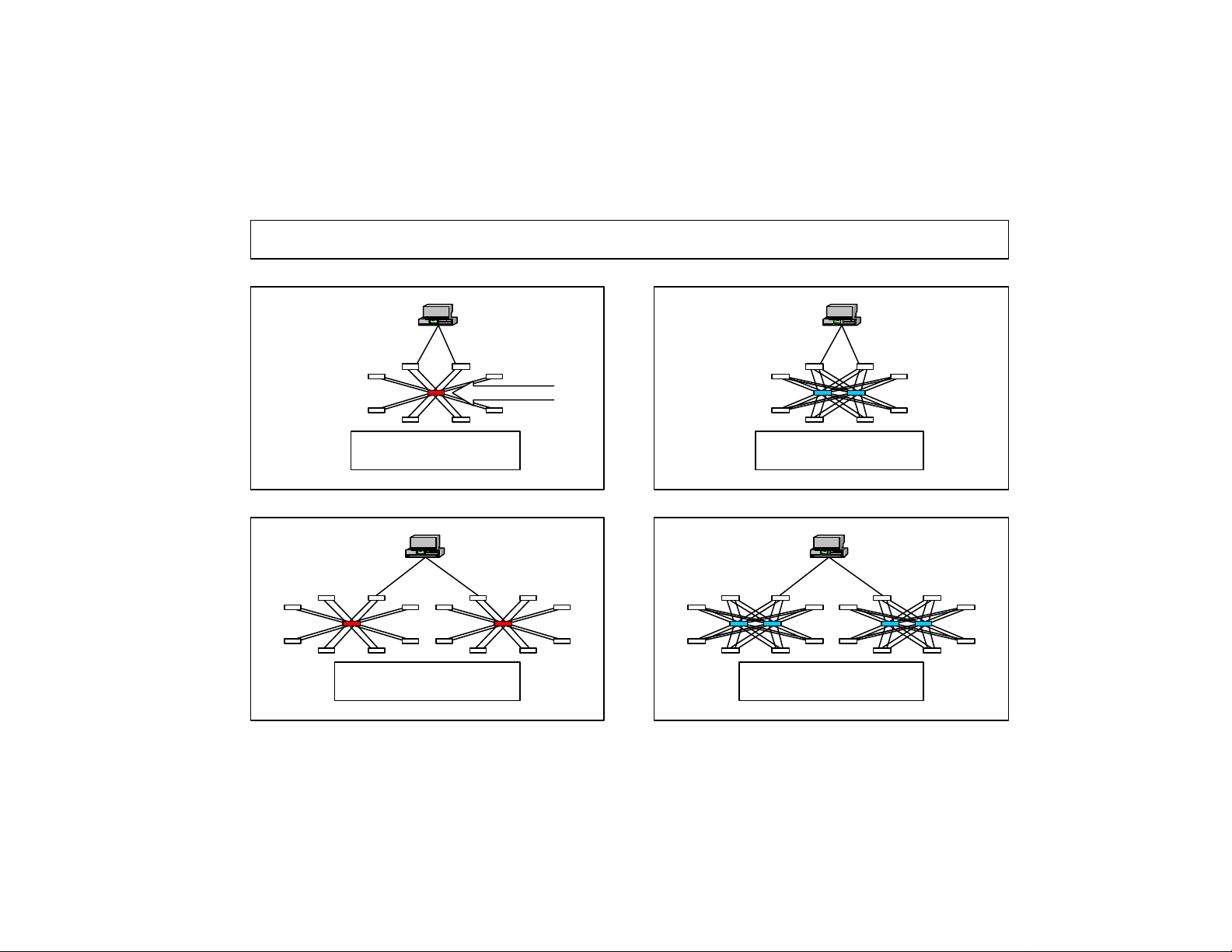
FIGURE 1. This Figure shows an example of each of the types of resilient designs.
Levels of Redundancy
SPF
Single fabric,
non-resilient
Dual fabric,
non-resilient
Single fabric,
resilient
Dual fabric,
resilient
The following discussion will be about single fabrics with resiliency. If a dual fabric, resilient design is desired (in fact, this is recom-
mended), simply pick the appropriate single fabric design and build two of them.
53-0001575-01 BROCADE Technical Note Page: 6 of 31
Page 7
SAN Design: March 29, 2001 3:18 pm
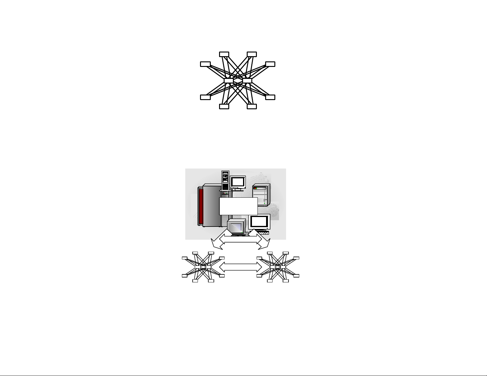
FIGURE 2. Two Core Switch, Two ISL, Star Design.
The above SAN is a single fabric, resilient design. To deploy a dual fabric, resilient SAN based upon this architecture, the following SAN
would be built
FIGURE 3. Dual Fabric Design, Hosts and Storage connection to Two Independent Fabrics:
Hosts and
Storage
Dual connections
No connection!
Redundancy builds in the ability to allow for SAN management to take place on one SAN while the other SAN stays in operation. For a site
where high availability is mandatory and where significant down time cannot be tolerated this design approach is the most prudent.
• When designing a fabric solution, consider using two redundant fabrics to provide the maximum flexibility in terms of SAN
downtime and maintenance. This solution will allow for:
53-0001575-01 BROCADE Technical Note Page: 7 of 31
Page 8

SAN Design: March 29, 2001 3:18 pm
• Switch upgrades can take place on one SAN (firmware, hardware, both) and while this SAN is down the
redundant SAN stays in operation
• A switch failure in one SAN allow for failover to the redundant SAN while the failed switch is replaced.
• Eliminates the single point of failure in the system - while highly meshed and redundant connections in a sin-
gle fabric are possible, the overall design of the SAN when installed as a redundant set of device inter-connects is
simpler to maintain and provides insurance against failure of a single fabric
2.3 SAMPLE SWITC H CONFIGURATIONS
This section provides a number so switch fabric designs using the topologies defined above. Simple switch designs are shown along with
more complex meshed fabric designs, Tier Architecture designs, and Star topology designs. This section also provides guidance on the
overall size in the form of port counts that can reliably be deployed today. As testing is completed for larger port count topologies they will
be added to this document.
53-0001575-01 BROCADE Technical Note Page: 8 of 31
Page 9
SAN Design: March 29, 2001 3:18 pm
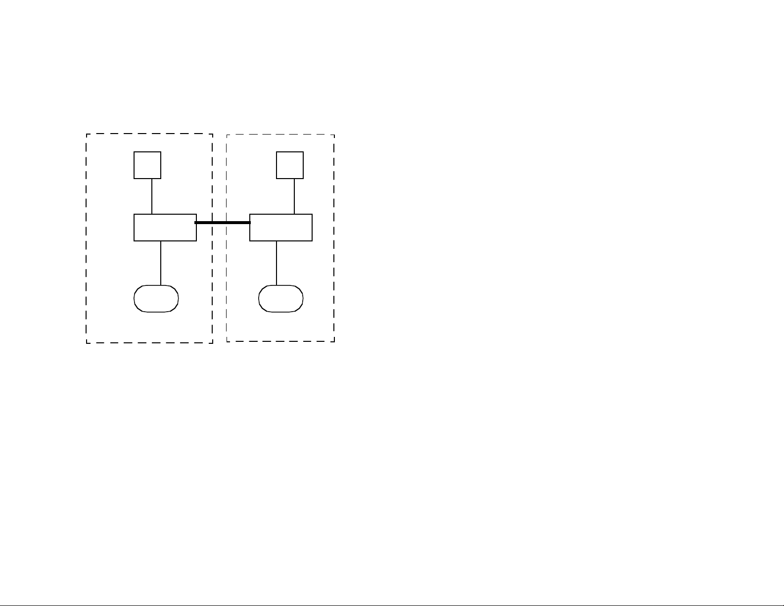
2.4 DUAL SWITCH HIGH AVAILABILITY CONFIGURATION - REDUNDANT FABRIC
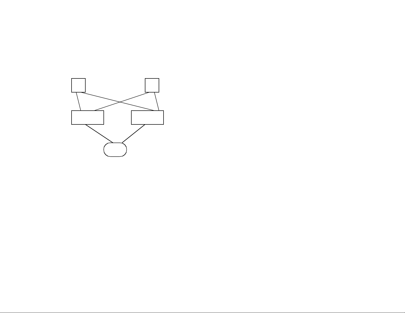
FIGURE 4. Two Fabrics -- Simplest Redundant Fabric Configuration
H
SW
H
SW
D
• Can use multiple hosts sharing single disk device, with redundant
paths in two fabrics
• Redundant switches, not combined into fabric
• Dual HBAs in hosts, host level software provides for failover to
alternate HBA when failure is noted in one HBA
• Dual ported storage allows for either host to access the same data
• With 8 port switches can support 4 hosts and two disk devices,
larger configurations possible with 16 port switches
H - host
SW - switch
D - storage device
53-0001575-01 BROCADE Technical Note Page: 9 of 31
Page 10
SAN Design: March 29, 2001 3:18 pm
2.5 TWO SWITC H FABRIC FOR MIRRORING AND DISASTER TOLERANCE
FIGURE 5. Extended Fabric Example
H
SW
D
10 KM
SW
D
H
• Sample configuration showing only two hosts and two storage
devices, larger configurations can be deployed
• This example shows how data being used at the local site can be
mirrored at a remote site via an extended fabric link. Primary system
data is replicated at remote site where a backup failover system is
located. Primary system disk information is mirrored to remote site that
can be 10KM distance with standard FC components (Long Wave
Length GBICs). Extended distances (20 to 120 KM possible) using
optical extender devices or DWDM devices.
• Starting with Fabric OS version 2.1.1, optional software to support
extended fabric is available. This allows increase in buffer-to-buffer
credits on E-ports to allow for maximum performance on links extended
over long distances. This option recommended when extended beyond
40KM.
• Mirroring across the link is accomplished by use of host based
mirroring software or by storage based mirroring options.
Local Site
Primary Compute Site
53-0001575-01 BROCADE Technical Note Page: 10 of 31
Remote Site
Activated when
primary site fails
• Note: this configuration does not show a highly available solution,
there are single points of failure -- it points out the concept of remotely
mirroring data for disaster tolerance; other more highly available
architected solutions are possible at both sites.
• Alternative designs are possible where both sites mirror to each
other; sites can also consist of multi-switch fabrics connected over an
extended link
Page 11

SAN Design: March 29, 2001 3:18 pm
2.6 HIGHLY AV AILABLE SMALL FABRIC CONFIGURATION
FIGURE 6. HIghly Available Small Fabric
H
SW SW
5
1
SW SW
• In this design, any switch can fail and there will still be an alternative
path to the host and storage devices. [Assumes hosts/storage have
D
intelligence to fail over.] Any single switch could be powered off for
servicing and replaced in the fabric without loosing device connectivity.
• This simple switch topology allows for multiple routes through the
2
fabric ensuring that any single inter-switch link failure (GBIC or cable) will
not result in loss of connectivity. BROCADE switches do automatic
failover to alternate link and will recompute routing tables for all N-port
6
3
devices.
• The typical path through the fabric for a host requires only one hop to
get to the storage. Should path 1 fail, traffic will route via 5 and 4 to get to
disk. If the switch fails, the alternate HBA in the host can be used to still
4
allow a single hop to the storage using path 6. Should paths 1 and 6 fail,
there is a still a three hop path to the storage device (2-3-4). This provides
for considerable resiliency and flexibility to fabric reconfigurations
• There are a number of host and storage suppliers that can provide for
D
H
detection of failed HBAs, failed paths, and failed ports on dual ported
storage devices and that will use host based software to initiate a failover
Numbers above are labels for the links, see text
scenario. At this time failover is managed by hosts or by intelligent RAID
systems that can detect the failure, it is not done by switch software
8 port switches -- 20 N-port devices
supported with max of 2 hops. Inter switch
Link failure always has alternate link
available at hop count penalty
16 port switches -- 52 N-port connections
• Storage in a fabric is globally available to all host elements (assuming
a shared storage file system is in place). Where this is not the case, and
storage is typically associated with a specific host, the storage is best
placed on the same switch as the host to minimize inter-switch link traffic.
• This design is appropriate when the fabric itself needs to be highly
available; a single switch can fail and/or be taken off-line for maintenance
and the fabric will still support all connected devices (devices do require
one redundant entry point to the fabric)
53-0001575-01 BROCADE Technical Note Page: 11 of 31
Page 12

SAN Design: March 29, 2001 3:18 pm
2.7 SAN BUILD ING BLOCK - MESHED FABRIC CONSISTING OF TWO STAR TOPOLOGIES CONNECTED BY A MESH
FIGURE 7. SAN Building Block showing expansion to 17 switch Mesh Fabric
SW
SW SW
SW
• An atomic building block of 8 switches (star) for larger SANs
• Design can be expanded horizontally or vertically- horizontal
expansion shown above using mesh design
• Redundant paths through the fabric by having at least two interswitch links per switch
• Note: nodes can be on exterior switches or on interior switches.
This will enable hosts/storage to be co-located on a switch if the
application/data is closely associated with the host. Or, the interior
switches can be used for storage devices shared by hosts on the
exterior switches, eliminating a hop in the host<--->storage
connection
SW SW
SW SW
SW
SW SW
SW
DESIGN GUIDANCE
- Recommend use of FOS version 2.1.9g/2.2.2 or higher
- Do not exceed 17 switches in this topology
- No more than three inter-switch links per edge switch
- Maximum ports 220 (single ISL)
- Max hops 6
- Take advantage of any known locality
SW SW
SW SW
• This basic 8 switch design with single ISL’s accommodates 104
end nodes
• When merging, connect the core switches using mesh
53-0001575-01 BROCADE Technical Note Page: 12 of 31
Page 13

SAN Design: March 29, 2001 3:18 pm
2.8 STA R TOPOLOGY DESIGN
In the traditional data networking world, star topology network has a core of networking equipment (hubs, switches, and routers) with other
equipment radiating out from this. A star topology SAN is fundamentally the same: It contains one or more “core” switches, surrounded by
one or more “edge” switches.
FIGURE 8.
Edge
Core
FIGURE 9. Star Topology -- with Core and Edge Switches
There is a difference between a fibre channel star architecture and a traditional data network star. Because the fibre channel routing protocol
FSPF provides superior load sharing characteristics, there could be as many as sixteen core units. If the star were built with future, higher
port count products, the count could be even higher. FSPF will distribute connections across all cores more or less evenly.
2.8.1 SIMPLE VS. COMPLEX CORES
Each core “unit” in a star SAN can be a single switch (simple), or a group of switches (complex). All of the examples given to this
point, there are two cores, each of which is a single switch.
53-0001575-01 BROCADE Technical Note Page: 13 of 31
Page 14

SAN Design: March 29, 2001 3:18 pm
FIGURE 10. Two Switch Core Star SAN Design
Two, single-switch cores
The strengths of this design are numerous. This provides lowest hop count design, uses the fewest switches for the given port count,
has the best and easiest to analyze performance characteristics, and is the simplest to build, understand, and maintain. Support for
more complex cores will be detailed in a future version of this document.
As long as the number of edge switches is equal to or less than the number of ports in each core switch, this design is the best to use.
For example, if the core is comprised of 16-port switches, there can be up to 16 edge switches with a simple core design:
53-0001575-01 BROCADE Technical Note Page: 14 of 31
Page 15

SAN Design: March 29, 2001 3:18 pm
FIGURE 11. Star Topologies shown with 2x16 port switch at the core and with 4x16 port switch at the core
Brocade has tested and validate star SAN designs today with our SilkWorm 2800 16 port switch. The two core switch topology
shown in Figure 5 is a very good typical SAN design that can support many network storage applications. There is a maximum port
count available of 224 ports. No more than two hops from any device to any device in the network. Equal cost paths for all devices
in the network meaning the fabric can load balance on initialization. The four switch core version retains many of the same benefits
for a maximum of 192 ports. The benefit of this design is added equal costs paths via the core to improve data throughput via the
core.
2.8.2 DESIGN CRITERIA /TESTED AND SUPPORTED CONFIGURATIONS:
• Maximum of 20 switches in Star topology
• Maximum of 4 switches in the core, 16 port
• Dual connections to core from edge switches allow for single switch core failure with no loss of connectivity
• Maximum port count of 224; 192 with 4 switch core
• Fewer switches can be used and the SAN can “grow” to maximum configuration
53-0001575-01 BROCADE Technical Note Page: 15 of 31
Page 16

SAN Design: March 29, 2001 3:18 pm
FIGURE 12. Star Topologies Possible with 2 switch cores
2.9 TIER DESIGN
53-0001575-01 BROCADE Technical Note Page: 16 of 31
Page 17

SAN Design: March 29, 2001 3:18 pm
Three Tier designs in general allow for higher port count fabrics over Star designs (using the same switch building blocks) but can add
additional hops to the design. A middle (core) set of switches can be used to provide connectivity between an upper and lower level of
switches. These designs are generally used when data traffic flows between devices attached to the top tier and devices on the bottom tier.
For example, hosts on the top tier and storage systems on the bottom. These kinds of connections will have minimal hop counts and also
multiple equal cost paths in the fabric to allow for load sharing. If devices at a given level need to communicate via the fabric, there may be
additional hops and less variety of paths for this communication. A sample of an acceptable tested three tier design is shown in Figure 10.
This particular design was used in Brocade’s Fabric Aware test program to validate heterogeneous device connectivity in a large SAN network.
FIGURE 13. Three Tier Design used in Fabric Aware Testing at Brocade
A1 A2 A8A3 A7A4 A5 A6 A9 A10 A11 A12 A13 A14
B1 B4
C1
C2 C3 C4 C5 C6
B3B2
Total of 268 ports available -- 196 host and 72 storage ports typical; total of 48 ISLs
There are a number of possible three tier designs that will work and that are generally in the 200 port count range. Shown in Figure 11 is
another example of an operating three tier design. This design includes an extended fabric link via DWDM allowing for connection of two
smaller SANs into a large SAN across a dark fiber link using DWDM equipment.
53-0001575-01 BROCADE Technical Note Page: 17 of 31
Page 18

SAN Design: March 29, 2001 3:18 pm
FIGURE 14. MUlti Tier SAN Design across an Extended Link
SITE 1
SITE 2
These links are via DWDM,
not shown in diagram.
DESIGN: 16 SWITCHES, TWO LOCATIONS; TOTA L PORTS= 212 USING 16 PORT SWITCHES
Depicted in the next diagram is a 20 switch fabric, three tier, with 4 switches at the core. This fabric offers 2 hops from source to destinations, with multiple equal cost paths between devices allowing for device failover without a performance lost due to added latency.
53-0001575-01 BROCADE Technical Note Page: 18 of 31
Page 19

SAN Design: March 29, 2001 3:18 pm
FIGURE 15. Twenty Switch Three Tier Design (also a Star configuration)
• 192 user ports total; total of 64 ISLs
• Multiple equal cost paths between end nodes via a redundant switch
• Maximum of two hops between devices
• Any to any connectivity however data flow from top to bottom and vice versa is expected
usage
• Core switches for interconnect only, no user devices
• Start with fewer switches and can grow to final configuration
53-0001575-01 BROCADE Technical Note Page: 19 of 31
Page 20

SAN Design: March 29, 2001 3:18 pm
2.9.1 SUMMA RY
A variety of SAN designs topologies and port counts can be deployed today using Brocade switch. The Fabric Operating System provides
for auto-discovery and configuration of the SAN as devices are added and new switches included in an existing SAN. The user should
understand his environment, the components in the SAN, the relationship between hosts and storage, usage patterns and his needs for reliability and redundancy when building a SAN. Information in this section can be used as guidance in choosing a design. The safe limits for
reliable SAN sizes supported as of this publication date are shown the Table 1 below.
FIGURE 16. SAN Topologies and Port Counts Supported by Brocade
Fabric Type
Meshed 16 2.1.9g+
Star 18-20 2.1.9g+
Three Tier 20-24 2.1.9g+
Switch
Count
FOS
Version
See Note
2.2.2+
2.2.2+
2.2.2+
NOTE:FOS release information. These versions of FOS are the recommended versions to use when targeting fabrics of the
size defined in this table. Later releases should work as well as denoted by the (+) symbol. The 2.2 Tree contains additional
licensed features not found in the 2.1 Tree of releases, however, in terms of compatibility and bug fixes the 2.1.9g and the
2.2.2 version are equivalent.
Port Count
Maximum
220 Single Port count max is with single ISL links in the mesh. Lower port counts if multiple ISL
224 One to each core
192-262 2 or more Figure 10 design: 190 host ports and 72 storage ports
ISL Comments
links are used.
Fewer switches can be used and the SAN can be expanded as to maximum configurafrom edge
switch
tion as more devices are added. Can still take advantage of locality if that is
known.however SAN allows for equal cost paths from any initiator to target.
Note: devices are not generally attached to the middle tier though it could be used for
device attach (add 12ports)
53-0001575-01 BROCADE Technical Note Page: 20 of 31
Page 21

SAN Design: March 29, 2001 3:18 pm
3.0 Additional Considerations in Fabric Design and Implementation
3.1 FABRIC BRING UP
A large (greater than 8) switch fabric will require care and planning on initial power up and for expanding switch elements. Bro-
cade has developed an extensive planning document to allow SAN administrators to successfully bring up, add to, delete from, and generally maintain a large switch fabric. Consult the following reference document on the Brocade Web Site for these details:
• Building and Scaling BROCADE SAN Fabrics: Large Fabric Bring Up and Maintenance Guide, Doc. # 53-
0001573-01
3.2 INTER-SWITC H LINKS (ISL)
Inter-switch links (E-port connections) provide for connection between switches. Multiple links can be setup between switches. Any switch
in the fabric can have one or more links to another switch in the fabric. At initial start-up of the switch, the links are allocated in a roundrobin fashion to balance the load on the system. On addition or deletion of an ISL, the Dynamic Load Sharing capability is used to re-compute routes in the traffic to balance ports across ISL paths. (In the current BROCADE switch versions, dynamic load balancing after path
initialization does not exist across these links.The BROCADE switch guarantees in-order delivery and dividing traffic from a given port
among available ISLs will violate the in-order delivery we enforce.)
• Some features of the SilkWorm can be used to increase inter-switch bandwidth. Adding an ISL between switches is dynamic and
can be done while the switch is active. Adding a new ISL will result in a routing re-computation and new allocation of ISL links
between source and destination ports. Similarly, removing a link will result in routing re-computation across the fabric and pos sible
fabric re-configuration. RSCNs are generated following these events sometimes causing I/O traffic to pause as nodes reauthenticate with the fabric.
• Adding ISL’s will cause routing traffic/zoning data to be updated across each ISL. The number of ISL’s is not so relevant as changing
ISL configuration--as each change will result in a re-calculation of routes in the fabric. When numerous fabric reconfigurations occur
(removing or adding links, downing/upping a switch, etc.) the load on the switches CPUs will be increased and some fabric events
may time out waiting on CPU response. While fabric reconfiguration is taking place, data is held pending the completion of new
route calculations. Extensive changes on an ongoing basis of ISLs can effect data traffic. Adding or deleting ISL’s should be done
on a planned basis when SAN utilization is low and grouped in a manner to minimize impact on the fabric.
• No more than 8 ISLs between any two switches is supported. More than 8 ports can be used on a switch for ISL traffic as long as
no more than 8 go to a single adjacent switch. A sample of a switch star inter-connect is shown in Figure 1.
53-0001575-01 BROCADE Technical Note Page: 21 of 31
Page 22

SAN Design: March 29, 2001 3:18 pm
FIGURE 17. Valid and Invalid Configurations using Inter Switch Links
Valid Configuration Using 16 ISL’s
Not Valid Config - 9 ISL’s
Between Two Switches
Note: connection of more than 8 ISLs leaving
7 or less open ports does not make sense for
traffic routing in a 16 port switch.
3.3 CABLING AND MEDIA INTERFACES
Fibre channel supports several cable and optical media interface options.
• The shortest supported optical cable length is 2 meters. Using shorter cables could exceed the expected signal output at the optical
GBIC and is not recommended per the Fibre Channel standards.
NOTE:Recent recommendations to the T11 standards group have resulted in approval of a shorter cable lengths as part of
the Fibre Channel standards. Lengths of 12 inches are in the final stages of being ratified by the standards group.
• With Short Wave Length GBICs (Gigabit Interface Connectors), cable lengths can be 200m (with 62.5 micron multi-mod fiber) or
500m (with 50 micron multi-mode fiber cable).
• With Long Wave Length GBICs, single mode fiber cable lengths of up to 10 KM are supported
• These cables and distances are what BROCADE supports with the standard shipping product and BROCADE components. A
BROCADE OEM switch model may use different components and may allow for different distances.
• Copper cabling is also supported. A passive copper GBIC can be used with cable lengths of up to 13m. The BROCADE supplied
GBIC uses an HSSDC connector [this connector type is an alternative to the DB-9 connector used in many Gigabit Link Module
(GLM) copper connections]. Active copper GBICS allow the distance to be increased to 30m. Copper is typically used intra-cabinet
53-0001575-01 BROCADE Technical Note Page: 22 of 31
Page 23

SAN Design: March 29, 2001 3:18 pm
for wiring components that do not need to be a long distance from the switch. Copper connections tend to be less expensive. If cost
is not a driver, designing a solution with all optical media will provide for greater flexibility in future system upgrades and expansion
and allow devices to be extended beyond the limits of one rack without having to replace any GBICs.
3.4 ZONING/NAME SPACE
Other considerations should also be weighed when designing a large switch count fabric. Some of these are:
• Total number of zones and zoned devices. The larger the zoning information, the more information content needs to be passed
between switches when the fabric re-configures. CPU cycles in each switch are used to accept, resolve, and re-set zone data. A
busy CPU can take too long to recognize new devices being attached to the fabric. Future versions of this document will contain
more specific data based on empirical testing, however the general rule is try and keep the number of zones down as the total switch
count increases. Zoning tables of several hundred entries have been tested and validated in the fabric sizes detailed in this
document.
• All switches need to have the same zoning information in order to be merged in a fabric. See the large port count fabric bring up
document referenced at the start of this section for details on adding switches with zoning to an existing fabric.
• Name Space -- name selection in zoning can be based on World Wide Name or on Domain/Port ID. Using the WWN provides for
more flexibility in moving devices in the fabric, the zoning follows the WWN no matter what port the device is plugged into the fabric.
However, CPU translation of the WWN to domain/port ID must take place imposing an additional processing load on the switches
in the fabric. Domain/PortID zoning will not require CPU translation and will also allow the hardware to enforce zoning. There is no
one right answer, just two options to choose from and each has benefits and drawbacks that need to be considered when designing
a zoning scheme.
• WWN based zoning: zoning follows device no matter what switch port; allows for moving cables and maintain-
ing zones. Drawback--requires CPU to translate WWN to port ID for zone checks
• Domain ID/Port ID based zoning: allows for hardware enforced zoning instead of software, no CPU translation
required, minimizes CPU load. Drawback -- if you move a cable the zoning table must be re-configured for the new
port.
• GUI Zoning Definition -- a zoning GUI tool that allows for specifications of zones using our Web Tools GUI is available in firmware
version 2.1 and later. This tool does require licensing of Web Tools as well as Zoning as added switch software options.
3.5 TOTAL SWITCH COU NT/PORT COUNT
The ultimate limitation in fabric design is a maximum of 239 physical switches, be they 8 or 16 port versions. This limit is imposed by the
actual number of domain IDs that can be uniquely established in the Fibre Channel Device ID header on the frames. The practical limit and
what has been tested is much fewer switches. BROCADE is currently testing and validating fabrics greater than 32 switches with as many
as 68 switches in the configuration. Table 1 in this document details the current tested switch/port count limits for fabrics. Future updates of
this table will result from testing taking place now with updated FOS releases and with testing performed on later iterations of the Fabric
OS. In addition, switch port count support will increase with next generation larger port count switches.
53-0001575-01 BROCADE Technical Note Page: 23 of 31
Page 24

SAN Design: March 29, 2001 3:18 pm
The total size of a switch fabric is related to a number of factors that can affect overall performance. Some factors include:
• Total nodes, entries in the name space. Name space table management as devices in the fabric change can effect overall fabric
performance as a reconfiguration is needed to accommodate changes
• Zoning entries, similar to names space, needs to be propagated through the fabric
• Error handling. Excessive errors by one or more devices can affect the performance of a single (or multiple) switches and could
effect a switch CPU’s ability to handle a fabric level request
The testing that Brocade performs includes attaching devices to all available fabric nodes, introducing errors into the fabric, making fabric
changes, updating zoning tables, and removing and adding switches. Fabric stability and the ability to recover from these events for a given
fabric size, topology and with and given FOS release are tested and validated. This testing is the basis for stating support for a larger fabric
size.
3.6 SWITCH HOP COUN T
Hop counts in a fabric are limited to 7 -- that is 7 links between a source connected device and a destination connected device. While this
number of hops is allowed, fewer hops are better. The Star designs discussed in the document have a maximum of 2 hops. The hop count
limit is set by the Fabric OS and is used to derive a frame hold-time value per switch. The hold-time value is the maximum amount of time
a frame can be held in a switch before it is dropped (class 3) or F_BSY (class 2) is returned. A frame would be held if its destination port is
not available. The hold-time is derived from the error detect time out value and the resource allocation time out value via a formula.
• E_D_TOV - error detect time out value. When this time is exceeded and the sending port has not been notified of receipt of data by
the receiving port for a transmission, this error condition occurs (2 sec default)
• R_A_TOV - resource allocation time out value. Time after which a fabric resource with a reported error condition that is not cle ared
when the fabric de-allocates the resource (10 sec default)
• Hold-time = (R_A_TOV - E_D_TOV) / (Hop Count +1) / 2 ms (where time value is in milliseconds. For 7 hops, and the default
E_D_TOV of 2000 milliseconds, the hold-time per switch is 500ms.
3.7 BLOCKIN G VS. NON-BLOCKING
The BROCADE switch is a non-blocking design. This means any two pairs of ports can be active and transferring data without blocking
transfer of data from another pair of ports. Each port is allocated a time slice to transfer data, and cut through routing occurs that allows for
immediate transfer of data from an input port to an output port if that port is free. Blocking occurs in a fabric design with multiple switches
when data from multiple sources must be sent to a single destination port, or when data is required to be sent across an inter-switch link
from multiple input ports. Data is ‘blocked’, i.e. buffered in the switch, and sent to the destination port based on the priority set of the data
(default priority for data based on virtual channels gives greater priority to F-port traffic on inter-switch links than data traffic). The nature
53-0001575-01 BROCADE Technical Note Page: 24 of 31
Page 25

SAN Design: March 29, 2001 3:18 pm
of Fibre Channel is that data is transferred based on buffer credits assigned to ports and sending and receiving devices manage the credits so
that there is never an overrun of data in the switch.
Blocking is also called over-subscription -- where multiple initiator ports are limited by ISL links or paths in the fabric and, for example, 3
devices must share a single link between switches [a switch with 12 N-port nodes and 4 ISLs is 3:1 over-subscription]. An ideal non-block-
ing design has a subscription ratio of 1:1. However many devices do not have a bandwidth that can saturate a Fibre Channel data path and
allowing multiple devices to share a data path given the bursty nature of much data traffic can still result in high performance with limited
blocking. Knowing your devices and the nature of your data usage is key to implementing a SAN design with good performance.
3.8 SAN MAN AGEMENT
The SilkWorm switch supports a number of management interfaces. These are:
• Telnet. A telnet session can be established with the switch that supports a command line interface. An administrator can login and
execute a number of commands that allow for showing switch status, port status, temperature and fan status, and for configuring
switch parameters. When BROCADE ZONING is licensed, a command line interface allows for defining fabric level zone
configurations.
Definition: ISL subscription is the ratio of input ports which might want to cross between
switches to the number of ISLs over which the traffic could cross. Over subscription occurs
when the ration is greater than 1:1.
• SNMP. Per the Fibre Channel FC-GS specifications, the SilkWorm switch supports a Fabric Element MIB and a BROCADE specific
MIB. Traps are defined for switch events and SNMP management software can be alerted to trap events. Similarly management
software can access switch information available via the telnet session.
• BROCADE WEB TOOLS. BROCADE supplies a licensed software option that allows Netscape or Internet Explorer browsers to
interact with an HTML server in the switch. A graphical view of all switches in the fabric is displayed and individual switch can be
selected for further drill down on switch/port information and for switch setup and configuration. Some OEMs have provided hooks
into SNMP management tools or custom disk management tools the invocation of web tools when switch management is required.
• SES (SCSI Enclosure Services). This is a programmatic interface within the switch that can be invoked from SCSI protocol as
defined in the SES specification. It allows for switch management via a host bus adapter that supports the SCSI FCA protocol. It
can be used when a separate out-of-band management tool is not desirable and when other device management is being conducted
via SES.
• Front Panel. The SilkWorm 2800 switch model (and 1600) feature a front key panel and display that supports most (but not all) telnet
commands. Basic switch addresses can be set, status information viewed, and configuration parameters set using the front panel.
With the large variety of management interfaces it is possible to accommodate a wide variety of SAN management approaches. The first
consideration should be decide if in-band (using FC protocol such as SES or using an HBA that supports IP over FC) or out-of-band management is preferred. Out-of-band would use the switch Ethernet port for connection to the fabric. It should be noted that the SilkWorm fabric supports the ability to connect to one switch in the fabric via the switch Ethernet port, and to then connect to all other switches in the
53-0001575-01 BROCADE Technical Note Page: 25 of 31
Page 26

SAN Design: March 29, 2001 3:18 pm
fabric using IP over fibre channel protocol across switch links, thus reducing the need for a large switch management network. This configuration requires the primary switch with the Ethernet connection to be configured as the gateway switch for the Fibre Channel IP network.
All other switches would have to have this switch configured as the gateway address. This reduces the complexity of having a full Ethernet
switch management network, but does make the gateway switch a single point of failure for the management interface.
Web Tools provides the most user friendly interface to switch management. Within WebTools there is also the option to connect to a switch
via telnet session should a command line interface be needed to set special debugging options or if the administrator prefers a command
line interface over a GUI.
A typical management approach would be to use an SNMP management tool to monitor the switch network (along with other network elements) and to set alarms/traps for key events that would trigger an administrative intervention. This could be switch down, port down, fan
failure, power supply failure, temperature out of range and similar events that require intervention. The administrator would get either the
IP address of the switch or (if the SNMP tool has been setup this way) an icon of the switch indicating an alarm. The admin could click on
the switch and have the SNMP management tool invoke WebTools for that switch. Further diagnosis and trouble shooting would occur via
the WebTools interface.
3.9 NON PUBLIC DEVICES AND EXISTING FC-AL DISK EQUIPMENT
Fibre Channel Arbitrated Loop (FC-AL) technology is used by a number of manufacturers in disk storage systems. It is the usual format
employed in JBODs and also the technology used behind some storage RAID controllers (which can also present a FC-AL interface or Fabric interface or both to a switch). BROCADE supplies a switch mode designated QuickLoop™ that allows for the attachment of non-public
FC-AL devices to the switch. If the host bus adapter driver does not support Fabric attachment, and only supports a private interface, then a
QuickLoop connection to the switch is required. QuickLoop is supported only on the SilkWorm 2000 series switches. The entire switch can
be a QuickLoop enabled switch (model 2100 and 2010) or a fabric switch model can have selected ports configured to be QuickLoop ports
(this is a separately licensed product from BROCADE). Up to two switches can be connected with an ISL to form one logical QuickLoop.
No more than one QuickLoop can be supported between one or two switches. All devices within a QuickLoop can communicate with each
other. Public devices attached to a non-QuickLoop port can communicate to the private QuickLoop devices using translative mode addressing (more on this later). The advantage of a switch employed in the QuickLoop mode over a hub is the fact that the switch provides for full
bandwidth on each port. If multiple devices are used on multiple QuickLoop ports, each set of devices attached to a physical port share the
full port bandwidth of 100 MBytes/second. In a hub attached device configuration all devices on a single loop share the maximum band-
53-0001575-01 BROCADE Technical Note Page: 26 of 31
Page 27

SAN Design: March 29, 2001 3:18 pm
width of 100 MBytes/sec. Thirty disks attached to a hub on a single physical loop will not perform as well as 5 disks attached to 6 switch
QuickLoop ports. Other advantages are:
• Loop tenancies can occur in parallel on different looplets. A loop tenancy occurs when a device takes control of the loop to perform
I/O and I/O to any other loop device is restricted. In most loop implementations only one device is allowed control (tenancy) at a time.
• Faults are isolated to a looplet [Looplet: a single switch port with attached loop devices that are part of larger logical loop], instead
of affecting the entire loop
• The switch management tools and port statistics and debugging data are available for monitoring and management of the
QuickLoop
The switch will isolate misbehaving devices on a given port from the rest of the switch attached devices and will not propagate LIPS from
a misbehaving device to other devices sharing a single logical loop. [Note: managed hubs provide a similar capability.]
It is possible to use a switch in QuickLoop mode to connect JBODs and other private devices without having to change software drivers
and have this be a plug-and-play solution. Software license upgrades to the QuickLoop switches can be used to provide for full fabric support when users are ready to migrate to fabrics.
Translative mode. This addressing option is built into the Fabric OS™ for SilkWorm. It allows for public devices to see and talk to private
devices. The private devices (typically disks in a JBOD attached to a switch FL-port) would normally only have 8 bit addresses and be
missing the Domain and Node address bits required for a public device. Translative mode provides a pseudo 24 bit address for these
devices and presents this “phantom address” to a public devices (typically a host) that wants to perform I/O to the disks. The switch detects
when traffic has a destination ID of this pseudo address and the FL-port translates the public address back into the ALPA for the device on
the loop (and vice-versa). There are limitations in total number of devices that can be on a loop in translative mode:
• SilkWorm 1000: 31 devices can have phantom public addresses in a single loop
• SilkWorm 2000: 125 devices can have phantom public addresses in a single loo p
53-0001575-01 BROCADE Technical Note Page: 27 of 31
Page 28

SAN Design: March 29, 2001 3:18 pm
4.0 Glossary
This glossary provides definitions for the fibre channel and switch terminology used in BROCADE guide .
TABLE 1. Glossary of Fibre Channel and SAN Design Terminology
Term Definition
Address Identifier
Value used to identify source or destination of a frame
ASIC Application-Specific Integrated Circuit
BROCADE Extended
Switch option that allows for interconnection of switches up to 100 KM
Fabric
BROCADE Web
Tools
BROCADE product that provides a graphical interface for monitoring and managing individual switches or entire
fabrics from standard workstations.
BROCADE Zoning BROCADE product that allows partitioning of fabric into logical groupings of devices. See also Zone
Domain ID As applies to switches in the BROCADE SilkWorm 2000 series, a unique number between 1 and 239 that identifies
the switch to the fabric.
E_D_TOV Error Detect Time-out Value. Time allowed for round-trip transmission before recovery is initiated. Can also be
defined as the minimum time an L_Port waits for sequence completion before initiating recovery. See also R_A_TOV
F-Port Fabric Port. A port that can transmit using fabric protocol and can interface over links. Can be used to connect
N_Ports to a switch.
Fabric A fibre channel network of two or more switches. Also called a “switched fabric.”
Fabric OS
TM
Proprietary operating system on BROCADE switches.
Fabric Watch
TM
BROCADE product that allows monitoring and configuration of fabric and switch elements.
FL-Port Fabric Loop Port. A port that can transmit under both fabric protocol and loop protocol. Can be used to connect
NL_Ports to a switch.
FLOGI Fabric Login. Process by which a node makes a logical connection to fabric. Used by ports to determine if fabric is
present, and if so to exchange service parameters with the fabric
53-0001575-01 BROCADE Technical Note Page: 28 of 31
Page 29

SAN Design: March 29, 2001 3:18 pm
TABLE 1. Glossary of Fibre Channel and SAN Design Terminology
Term Definition
Frame Fibre channel structure used to transmit data. Consists of start-of-frame delimiter, header, any optional headers, data
payload, cyclic redundancy check (CRC), and end-of-frame delimiter. There are two types: data frames and link control frames. Similar to the networking concept “packet”.
FSPF Fabric Shortest Path First. BROCADE routing protocol for fibre channel switches
G-Port Generic Port. Port that can operate either as E_Port or F_Port. Ports are defined as G_Ports when disconnected or have
not assumed specific function within fabric
GBIC Gigabit Interface Converter -- converts electrical to optical signal
HBA Host Bus Adapter. Interface card between a server or workstation bus and the fibre channel network. Similar to a net-
work interface card
ISL Interswitch Link. Fibre channel link from the E_Port of one switch to E_Port of another.
JBOD Just a Bunch Of Disks. A number of disks connected in a single chassis to one or more controllers
Latency Time required to transmit a frame, from the time sent until time of arrival.
Link As applies to fibre channel, a physical connection between two ports, consisting of both transmit and receive fibres
LWL GBIC Long wavelength fibre optic GBIC. Based on 1300 nm lasers supporting 1.0625 Gbps link speeds. Connectors are
color-coded blue.
MIB Management Information Base. SNMP structure that provides configuration and device information to assist with
device management
Name Server Service of storing names, addresses, and attributes for up to 15 minutes, provided by a switch to other entities in fab-
ric. Defined by fibre channel standards, and existing at a well-known address. Also called Simple Name Server, SNS,
or directory service
N-Port Node Port. Port that can attach to a fibre channel port.
Storage Area Network. Network of systems and storage devices that usually communicate using fibre channel protocols.
SWL GBIC Short wavelength fiber-optic cable. Based on 850 nm lasers supporting 1.0625 Gbps link speeds. Connectors are
color-coded black.
53-0001575-01 BROCADE Technical Note Page: 29 of 31
Page 30

SAN Design: March 29, 2001 3:18 pm
TABLE 1. Glossary of Fibre Channel and SAN Design Terminology
Term Definition
Topology As applies to fibre channel, the structure of the fibre channel network and the resulting possible communication paths.
There are three fibre channel topologies: point-to-point, fabric, and arbitrated loop.
Zone Set of hosts and devices attached to same fabric and having access permission, including RSCNs and user data, to
each other. Entities inside a zone are not visible to entities outside the same zone, even if the outside entities are in
another zone.
Meshed Topology
Star Topology
Tier Architecture
Meshed Topology-- a network of switches that has at least one link to each adjacent switch. Fully meshed designs will have a connection from each switch in
the fabric to all other switches in the fabric. Other topologies are a specific instance of a mesh design.
Star Topology-- central switch(es) with some or all ports used to connect to other switches; edge switches connect only to the center switches
Tier Architecture -- a switch hierarchy of two or more levels with inter switch connections that assume data paths go from one side (hosts) to the other side
(targets).
53-0001575-01 BROCADE Technical Note Page: 30 of 31
Page 31

SAN Design: March 29, 2001 3:18 pm
Copyright
IMPORTANT NOTICE
This document is the property of BROCADE. It is intended solely as an aid for installing and configuring Storage Area Networks constructed with
BROCADE switches. This document does not provide a warranty to any BROCADE software, equipment, or service, nor does it imply product
availability. BROCADE is not responsible for the use of this document and does not guarantee the results of its use. BROCADE does not warrant
or guarantee that anyone will be able to recreate or achieve the results described in this document. The installation and configuration described in
this document made use of third party software and hardware. BROCADE does not make any warranties or guarantees concerning such third party
software and hardware.
2001, Brocade Communications Systems, Incorporated.
ALL RIGHTS RESERVED. Part number: 53-0000023-03
BROCADE, SilkWorm, SilkWorm Express, and the BROCADE logo are trademarks or registered trademarks of Brocade Communications
Systems, Inc., in the United States and/or in other countries.
All other brands, products, or service names are or may be trademarks or service marks of, and are used to identify, products or services of their
respective owners.
NOTICE: This document is for informational purposes only and does not set forth any warranty, express or implied, concerning any equipm ent, equipment feature, or
service offered or to be offered by BROCADE. BROCADE reserves the right to make changes to this document at any time, without notice, and assumes no
responsibility for its use. This informational document describes features that may not be currently available. Contact a BROCADE sales office for information
on feature and product availability.
Export of technical data contained in this document may require an export license from the United States Government.
Brocade Communications Systems, Incorporated
1745 Technology Drive
San Jose, CA 95110
53-0001575-01 BROCADE Technical Note Page: 31 of 31
 Loading...