

Page 1

53-1001583-01
53-1001583-01
21 June 2010
Brocade Adapters
Administrator’s Guide
Supporting HBA models 825, 815, 804, 425, 415
®
Page 2

Copyright © 2008-2010 Brocade Communications Systems, Inc. All Rights Reserved.
Brocade, the B-wing symbol, BigIron, DCX, Fabric OS, FastIron, IronPoint, IronShield, IronView, IronWare, JetCore, NetIron,
SecureIron, ServerIron, StorageX, and TurboIron are registered trademarks, and DCFM, Extraordinary Networks, and SAN Health
are trademarks of Brocade Communications Systems, Inc., in the United States and/or in other countries. All other brands,
products, or service names are or may be trademarks or service marks of, and are used to identify, products or services of their
respective owners.
Notice: This document is for informational purposes only and does not set forth any warranty, expressed or implied, concerning
any equipment, equipment feature, or service offered or to be offered by Brocade. Brocade reserves the right to make changes to
this document at any time, without notice, and assumes no responsibility for its use. This informational document describes
features that may not be currently available. Contact a Brocade sales office for information on feature and product availability.
Export of technical data contained in this document may require an export license from the United States government.
The authors and Brocade Communications Systems, Inc. shall have no liability or responsibility to any person or entity with
respect to any loss, cost, liability, or damages arising from the information contained in this book or the computer programs that
accompany it.
The product described by this document may contain “open source” software covered by the GNU General Public License or other
open source license agreements. To find out which open source software is included in Brocade products, view the licensing
terms applicable to the open source software, and obtain a copy of the programming source code, please visit
http://www.brocade.com/support/oscd.
Brocade Communications Systems, Incorporated
Corporate and Latin American Headquarters
Brocade Communications Systems, Inc.
1745 Technology Drive
San Jose, CA 95110
Tel: 1-408-333-8000
Fax: 1-408-333-8101
E-mail: info@brocade.com
European Headquarters
Brocade Communications Switzerland Sàrl
Centre Swissair
Tour B - 4ème étage
29, Route de l'Aéroport
Case Postale 105
CH-1215 Genève 15
Switzerland
Tel: +41 22 799 5640
Fax: +41 22 799 5641
E-mail: emea-info@brocade.com
Asia-Pacific Headquarters
Brocade Communications Systems China HK, Ltd.
No. 1 Guanghua Road
Chao Yang District
Units 2718 and 2818
Beijing 100020, China
Tel: +8610 6588 8888
Fax: +8610 6588 9999
E-mail: china-info@brocade.com
Asia-Pacific Headquarters
Brocade Communications Systems Co., Ltd. (Shenzhen WFOE)
Citic Plaza
No. 233 Tian He Road North
Unit 1308 – 13th Floor
Guangzhou, China
Tel: +8620 3891 2000
Fax: +8620 3891 2111
E-mail: china-info@brocade.com
Document History
Title Publication number Summary of changes Date
Brocade Adapters Administrator’s Guide
Supporting HBA models 415, 425, 815, 825
Brocade Adapters Administrator’s Guide
Supporting HBA models 825, 815, 804, 425,
415
53-1000881-01 New document June 2008
53-1001583-01 Updates to support the HBA
model 804 (mezzanine card for
the Hewlett Packard Blade
server)
June 2010
Page 3

Contents
About This Document
In this section . . . . . . . . . . . . . . . . . . . . . . . . . . . . . . . . . . . . . . . . . . . . ix
How this document is organized . . . . . . . . . . . . . . . . . . . . . . . . . . . . . ix
Document conventions. . . . . . . . . . . . . . . . . . . . . . . . . . . . . . . . . . . . . x
Text formatting . . . . . . . . . . . . . . . . . . . . . . . . . . . . . . . . . . . . . . . . x
Notes, cautions, and warnings . . . . . . . . . . . . . . . . . . . . . . . . . . . x
Key terms . . . . . . . . . . . . . . . . . . . . . . . . . . . . . . . . . . . . . . . . . . . .xi
Notice to the reader . . . . . . . . . . . . . . . . . . . . . . . . . . . . . . . . . . . . . . . xi
Additional information. . . . . . . . . . . . . . . . . . . . . . . . . . . . . . . . . . . . . . xi
Brocade resources. . . . . . . . . . . . . . . . . . . . . . . . . . . . . . . . . . . . . xi
Other industry resources. . . . . . . . . . . . . . . . . . . . . . . . . . . . . . . xii
Getting technical help. . . . . . . . . . . . . . . . . . . . . . . . . . . . . . . . . . . . . xii
Related documentation . . . . . . . . . . . . . . . . . . . . . . . . . . . . . . . . . . . xii
Document feedback . . . . . . . . . . . . . . . . . . . . . . . . . . . . . . . . . . . . . . xiii
Chapter 1 Host Management Overview
In this chapter . . . . . . . . . . . . . . . . . . . . . . . . . . . . . . . . . . . . . . . . . . . . 1
Host bus adapters. . . . . . . . . . . . . . . . . . . . . . . . . . . . . . . . . . . . . . . . . 1
HCM software . . . . . . . . . . . . . . . . . . . . . . . . . . . . . . . . . . . . . . . . . . . . 2
HCM features. . . . . . . . . . . . . . . . . . . . . . . . . . . . . . . . . . . . . . . . . . . . . 2
Tree node pop-up menus . . . . . . . . . . . . . . . . . . . . . . . . . . . . . . . . . . . 3
Adapter support. . . . . . . . . . . . . . . . . . . . . . . . . . . . . . . . . . . . . . . . . . . 4
Chapter 2 Getting Started with HCM Software
In this chapter . . . . . . . . . . . . . . . . . . . . . . . . . . . . . . . . . . . . . . . . . . . . 5
HCM software launch . . . . . . . . . . . . . . . . . . . . . . . . . . . . . . . . . . . . . . 5
Launching the application on Windows platforms. . . . . . . . . . . . 5
Launching the application on Linux platforms. . . . . . . . . . . . . . . 6
Remember password. . . . . . . . . . . . . . . . . . . . . . . . . . . . . . . . . . . 6
Skip login . . . . . . . . . . . . . . . . . . . . . . . . . . . . . . . . . . . . . . . . . . . . 6
Changing an HCM application password . . . . . . . . . . . . . . . . . . . 6
Changing an HCM agent password. . . . . . . . . . . . . . . . . . . . . . . . 7
Brocade Adapters Administrator’s Guide iii
53-1001583-01
Page 4

Software downgrade using Adapter Software Installer . . . . . . . . . . . 9
Downgrading HCM and driver or HCM only . . . . . . . . . . . . . . . . . 9
Downgrading driver only . . . . . . . . . . . . . . . . . . . . . . . . . . . . . . . . 9
HCM configuration data . . . . . . . . . . . . . . . . . . . . . . . . . . . . . . . . 9
Backing up data after an uninstall . . . . . . . . . . . . . . . . . . . . . . .10
Data restoration . . . . . . . . . . . . . . . . . . . . . . . . . . . . . . . . . . . . . .10
HCM main window . . . . . . . . . . . . . . . . . . . . . . . . . . . . . . . . . . . . . . . 12
Legend Help menu . . . . . . . . . . . . . . . . . . . . . . . . . . . . . . . . . . . . . . . 13
HCM product icons. . . . . . . . . . . . . . . . . . . . . . . . . . . . . . . . . . . . 13
Event severity icons . . . . . . . . . . . . . . . . . . . . . . . . . . . . . . . . . . . 14
Discovery . . . . . . . . . . . . . . . . . . . . . . . . . . . . . . . . . . . . . . . . . . . . . . . 14
Setting up out-of-band discovery for an adapter . . . . . . . . . . . . 15
Logging off HCM . . . . . . . . . . . . . . . . . . . . . . . . . . . . . . . . . . . . . . . . .16
Chapter 3 Host Configuration
In this chapter . . . . . . . . . . . . . . . . . . . . . . . . . . . . . . . . . . . . . . . . . . . 17
Host security authentication . . . . . . . . . . . . . . . . . . . . . . . . . . . . . . .17
Configuring security authentication using HCM (Host and HBA)17
Configuring security authentication using the BCU. . . . . . . . . . 19
Buffer credits. . . . . . . . . . . . . . . . . . . . . . . . . . . . . . . . . . . . . . . . . . . .20
Basic port configuration . . . . . . . . . . . . . . . . . . . . . . . . . . . . . . . . . . .20
Opening the Basic Port Configuration dialog box . . . . . . . . . . .21
Port logging level . . . . . . . . . . . . . . . . . . . . . . . . . . . . . . . . . . . . . 21
Boot over SAN . . . . . . . . . . . . . . . . . . . . . . . . . . . . . . . . . . . . . . . . . . . 28
Configuring Boot over SAN . . . . . . . . . . . . . . . . . . . . . . . . . . . . .28
Pre-boot configuration. . . . . . . . . . . . . . . . . . . . . . . . . . . . . . . . .30
Boot image update. . . . . . . . . . . . . . . . . . . . . . . . . . . . . . . . . . . . 31
Virtual port configuration . . . . . . . . . . . . . . . . . . . . . . . . . . . . . . . . . .32
Virtual port restrictions . . . . . . . . . . . . . . . . . . . . . . . . . . . . . . . .32
Creating a virtual port . . . . . . . . . . . . . . . . . . . . . . . . . . . . . . . . .32
Deleting a virtual port . . . . . . . . . . . . . . . . . . . . . . . . . . . . . . . . . 33
HCM logging levels . . . . . . . . . . . . . . . . . . . . . . . . . . . . . . . . . . . . . . . 34
Configuring the HCM logging level using HCM. . . . . . . . . . . . . .34
Advanced port configuration . . . . . . . . . . . . . . . . . . . . . . . . . . . . . . . 35
Opening the Advanced Port Configuration dialog box. . . . . . . .35
Interrupt Control Coalesce . . . . . . . . . . . . . . . . . . . . . . . . . . . . . 36
Name configuration . . . . . . . . . . . . . . . . . . . . . . . . . . . . . . . . . . . . . . 37
Dual role changes . . . . . . . . . . . . . . . . . . . . . . . . . . . . . . . . . . . . 37
Name validation. . . . . . . . . . . . . . . . . . . . . . . . . . . . . . . . . . . . . .37
Defining a name. . . . . . . . . . . . . . . . . . . . . . . . . . . . . . . . . . . . . .38
Editing the name fields . . . . . . . . . . . . . . . . . . . . . . . . . . . . . . . .38
Adding name entries . . . . . . . . . . . . . . . . . . . . . . . . . . . . . . . . . .39
Removing a name entry. . . . . . . . . . . . . . . . . . . . . . . . . . . . . . . .40
Exporting the properties for a WWN . . . . . . . . . . . . . . . . . . . . . . 40
Importing the properties for a WWN. . . . . . . . . . . . . . . . . . . . . . 41
Importing duplicated names . . . . . . . . . . . . . . . . . . . . . . . . . . . .43
iv Brocade Adapters Administrator’s Guide
53-1001583-01
Page 5

NPIV . . . . . . . . . . . . . . . . . . . . . . . . . . . . . . . . . . . . . . . . . . . . . . . . . . . 44
Chapter 4 Monitoring
In this chapter . . . . . . . . . . . . . . . . . . . . . . . . . . . . . . . . . . . . . . . . . . .45
Performance monitoring. . . . . . . . . . . . . . . . . . . . . . . . . . . . . . . . . . . 45
Polling frequency rate . . . . . . . . . . . . . . . . . . . . . . . . . . . . . . . . . 46
Resetting statistics . . . . . . . . . . . . . . . . . . . . . . . . . . . . . . . . . . . 46
Master log . . . . . . . . . . . . . . . . . . . . . . . . . . . . . . . . . . . . . . . . . . . . . . 47
Application log . . . . . . . . . . . . . . . . . . . . . . . . . . . . . . . . . . . . . . . . . . .50
Syslog support. . . . . . . . . . . . . . . . . . . . . . . . . . . . . . . . . . . . . . . . . . .51
Opening the Syslog Server Configuration dialog box. . . . . . . . . 51
Registering a host server. . . . . . . . . . . . . . . . . . . . . . . . . . . . . . . 51
Removing a host server. . . . . . . . . . . . . . . . . . . . . . . . . . . . . . . . 52
Syslog host configuration using VMware . . . . . . . . . . . . . . . . . . 52
Chapter 5 Diagnostics
In this chapter . . . . . . . . . . . . . . . . . . . . . . . . . . . . . . . . . . . . . . . . . . .53
Diagnostics using the BCU . . . . . . . . . . . . . . . . . . . . . . . . . . . . . . . . . 53
Diagnostics using HCM. . . . . . . . . . . . . . . . . . . . . . . . . . . . . . . . . . . .55
Displaying test log details. . . . . . . . . . . . . . . . . . . . . . . . . . . . . . . . . . 58
Beaconing . . . . . . . . . . . . . . . . . . . . . . . . . . . . . . . . . . . . . . . . . . . . . .59
SFP management . . . . . . . . . . . . . . . . . . . . . . . . . . . . . . . . . . . . . . . .60
Debugging . . . . . . . . . . . . . . . . . . . . . . . . . . . . . . . . . . . . . . . . . . . . . .61
supportSave . . . . . . . . . . . . . . . . . . . . . . . . . . . . . . . . . . . . . . . . . . . . 61
Appendix A HCM Dialog Boxes
In this appendix. . . . . . . . . . . . . . . . . . . . . . . . . . . . . . . . . . . . . . . . . . 65
Authentication Statistics dialog box. . . . . . . . . . . . . . . . . . . . . . . . . . 67
Backup dialog box. . . . . . . . . . . . . . . . . . . . . . . . . . . . . . . . . . . . . . . . 69
Base Port Properties panel . . . . . . . . . . . . . . . . . . . . . . . . . . . . . . . .70
Change HCM Password dialog box. . . . . . . . . . . . . . . . . . . . . . . . . . . 71
Change HCM Agent Password dialog box . . . . . . . . . . . . . . . . . . . . .72
Configure Names dialog box . . . . . . . . . . . . . . . . . . . . . . . . . . . . . . .73
Define Name dialog box . . . . . . . . . . . . . . . . . . . . . . . . . . . . . . . . . . . 75
Duplicated Names dialog box. . . . . . . . . . . . . . . . . . . . . . . . . . . . . . . 76
Event Properties dialog box . . . . . . . . . . . . . . . . . . . . . . . . . . . . . . . .77
Fabric Statistics dialog box. . . . . . . . . . . . . . . . . . . . . . . . . . . . . . . . .78
FCP IM Statistics dialog box . . . . . . . . . . . . . . . . . . . . . . . . . . . . . . . .79
FCP IM Module Statistics dialog box . . . . . . . . . . . . . . . . . . . . . . . . . 81
Brocade Adapters Administrator’s Guide v
53-1001583-01
Page 6

Fibre Channel Security Protocol Configuration dialog box . . . . . . .83
Hardware Tests Diagnostics dialog box . . . . . . . . . . . . . . . . . . . . . . .85
HBA Properties panel . . . . . . . . . . . . . . . . . . . . . . . . . . . . . . . . . . . . .86
IOC Statistics dialog box . . . . . . . . . . . . . . . . . . . . . . . . . . . . . . . . . . .88
Logical Port Statistics dialog box . . . . . . . . . . . . . . . . . . . . . . . . . . . .93
LPORT Properties panel . . . . . . . . . . . . . . . . . . . . . . . . . . . . . . . . . . .95
Master Log tab . . . . . . . . . . . . . . . . . . . . . . . . . . . . . . . . . . . . . . . . . .96
Master Log Filter dialog box . . . . . . . . . . . . . . . . . . . . . . . . . . . . . . . .97
Persistent Binding dialog box . . . . . . . . . . . . . . . . . . . . . . . . . . . . . . .98
Port Properties panel . . . . . . . . . . . . . . . . . . . . . . . . . . . . . . . . . . . . .99
Port Statistics dialog box . . . . . . . . . . . . . . . . . . . . . . . . . . . . . . . . . 101
Protocol Tests dialog box . . . . . . . . . . . . . . . . . . . . . . . . . . . . . . . . .103
QoS Statistics dialog box . . . . . . . . . . . . . . . . . . . . . . . . . . . . . . . . .104
Remote Port Properties panel . . . . . . . . . . . . . . . . . . . . . . . . . . . . .105
Restore dialog box. . . . . . . . . . . . . . . . . . . . . . . . . . . . . . . . . . . . . . .106
SFP Properties panel . . . . . . . . . . . . . . . . . . . . . . . . . . . . . . . . . . . . 107
Syslog Server Configuration dialog box . . . . . . . . . . . . . . . . . . . . . .109
Target Statistics dialog box. . . . . . . . . . . . . . . . . . . . . . . . . . . . . . . .110
Test Log Details dialog box . . . . . . . . . . . . . . . . . . . . . . . . . . . . . . . .114
Virtual Port Creation dialog box . . . . . . . . . . . . . . . . . . . . . . . . . . . .115
Virtual Port Deletion dialog box . . . . . . . . . . . . . . . . . . . . . . . . . . . .116
Virtual Port Properties panel . . . . . . . . . . . . . . . . . . . . . . . . . . . . . .117
Virtual Port Statistics dialog box . . . . . . . . . . . . . . . . . . . . . . . . . . .118
Appendix B Brocade Command Utility
In this appendix. . . . . . . . . . . . . . . . . . . . . . . . . . . . . . . . . . . . . . . . .121
About the BCU . . . . . . . . . . . . . . . . . . . . . . . . . . . . . . . . . . . . . . . . . .122
BCU commands. . . . . . . . . . . . . . . . . . . . . . . . . . . . . . . . . . . . . . . . .122
adapter. . . . . . . . . . . . . . . . . . . . . . . . . . . . . . . . . . . . . . . . . . . . . . . .126
auth . . . . . . . . . . . . . . . . . . . . . . . . . . . . . . . . . . . . . . . . . . . . . . . . . .128
bios. . . . . . . . . . . . . . . . . . . . . . . . . . . . . . . . . . . . . . . . . . . . . . . . . . .131
boot . . . . . . . . . . . . . . . . . . . . . . . . . . . . . . . . . . . . . . . . . . . . . . . . . .133
debug . . . . . . . . . . . . . . . . . . . . . . . . . . . . . . . . . . . . . . . . . . . . . . . . .135
diag . . . . . . . . . . . . . . . . . . . . . . . . . . . . . . . . . . . . . . . . . . . . . . . . . .137
drvconf . . . . . . . . . . . . . . . . . . . . . . . . . . . . . . . . . . . . . . . . . . . . . . . .139
fabric . . . . . . . . . . . . . . . . . . . . . . . . . . . . . . . . . . . . . . . . . . . . . . . . .140
fcdiag . . . . . . . . . . . . . . . . . . . . . . . . . . . . . . . . . . . . . . . . . . . . . . . . .141
vi Brocade Adapters Administrator’s Guide
53-1001583-01
Page 7

fcpim . . . . . . . . . . . . . . . . . . . . . . . . . . . . . . . . . . . . . . . . . . . . . . . . .143
ioc. . . . . . . . . . . . . . . . . . . . . . . . . . . . . . . . . . . . . . . . . . . . . . . . . . . .145
log. . . . . . . . . . . . . . . . . . . . . . . . . . . . . . . . . . . . . . . . . . . . . . . . . . . . 147
lport . . . . . . . . . . . . . . . . . . . . . . . . . . . . . . . . . . . . . . . . . . . . . . . . . .148
pbind . . . . . . . . . . . . . . . . . . . . . . . . . . . . . . . . . . . . . . . . . . . . . . . . .150
port. . . . . . . . . . . . . . . . . . . . . . . . . . . . . . . . . . . . . . . . . . . . . . . . . . .151
qos . . . . . . . . . . . . . . . . . . . . . . . . . . . . . . . . . . . . . . . . . . . . . . . . . . .155
ratelim . . . . . . . . . . . . . . . . . . . . . . . . . . . . . . . . . . . . . . . . . . . . . . . .156
rport . . . . . . . . . . . . . . . . . . . . . . . . . . . . . . . . . . . . . . . . . . . . . . . . . .157
vport . . . . . . . . . . . . . . . . . . . . . . . . . . . . . . . . . . . . . . . . . . . . . . . . . .160
Appendix C HCM Troubleshooting
In this appendix. . . . . . . . . . . . . . . . . . . . . . . . . . . . . . . . . . . . . . . . .163
Appendix D Glossary and Acronyms
Index
Brocade Adapters Administrator’s Guide vii
53-1001583-01
Page 8

viii Brocade Adapters Administrator’s Guide
53-1001583-01
Page 9

About This Document
In this section
•How this document is organized . . . . . . . . . . . . . . . . . . . . . . . . . . . . . . . . . . . ix
•Document conventions . . . . . . . . . . . . . . . . . . . . . . . . . . . . . . . . . . . . . . . . . . . x
•Notice to the reader . . . . . . . . . . . . . . . . . . . . . . . . . . . . . . . . . . . . . . . . . . . . . xi
•Additional information. . . . . . . . . . . . . . . . . . . . . . . . . . . . . . . . . . . . . . . . . . . . xi
•Getting technical help . . . . . . . . . . . . . . . . . . . . . . . . . . . . . . . . . . . . . . . . . . . xii
•Related documentation. . . . . . . . . . . . . . . . . . . . . . . . . . . . . . . . . . . . . . . . . . xii
•Document feedback . . . . . . . . . . . . . . . . . . . . . . . . . . . . . . . . . . . . . . . . . . . . xiii
How this document is organized
. This document is organized to help you find the information that you want as quickly and easily as
possible.
The document contains the following components:
• Chapter 1, “Host Management Overview,” provides a description of the Host Connectivity
Manager (HCM) application software, the graphical user interface (GUI), system requirements,
and supported operating systems.
• Chapter 2, “Getting Started with HCM Software,” explains how to launch the management
software, set security passwords, discover SAN components, and log out.
• Chapter 3, “Host Configuration,” provides the procedures to configure operating parameters
(basic and advanced), security authentication, and persistent binding using the Brocade
Command Line Utility (BCU) or the GUI.
• Chapter 4, “Monitoring,” describes the HCM monitoring features.
• Chapter 5, “Diagnostics,” describes the non-destructive group of diagnostic commands that
can be run from the BCU or the GUI.
• Appendix A, “HCM Dialog Boxes,” lists the fields that are associated with the HCM GUI and
provides a definition for each field.
• Appendix B, “Brocade Command Utility,” provides reference information for the Host
Connectivity Manager (HCM) commands that can be run from the Brocade Command Line
Utility (BCU)
• Appendix C, “HCM Troubleshooting,” provides a summary of HCM navigation problems and
workarounds.
• Appendix D, “Glossary and Acronyms,” provides reference information for common terms and
acronyms.
Brocade Adapters Administrator’s Guide ix
53-1001583-01
Page 10

Document conventions
NOTE
ATTENTION
CAUTION
DANGER
This section describes text formatting conventions and important notice formats used in this
document.
Text formatting
The narrative-text formatting conventions that are used are as follows:
bold text Identifies command names
italic text Provides emphasis
code text Identifies CLI output
For readability, command names in the narrative portions of this guide are presented in mixed
lettercase: for example, switchShow. In actual examples, command lettercase is often all
lowercase. Otherwise, this manual specifically notes those cases in which a command is case
sensitive.
Identifies the names of user-manipulated GUI elements
Identifies keywords and operands
Identifies text to enter at the GUI or CLI
Identifies variables
Identifies paths and Internet addresses
Identifies document titles
Identifies command syntax examples
Notes, cautions, and warnings
The following notices and statements are used in this manual. They are listed below in order of
increasing severity of potential hazards.
A note provides a tip, guidance or advice, emphasizes important information, or provides a reference
to related information.
An Attention statement indicates potential damage to hardware or data.
A Caution statement alerts you to situations that can be potentially hazardous to you or cause
damage to hardware, firmware, software, or data.
A Danger statement indicates conditions or situations that can be potentially lethal or extremely
hazardous to you. Safety labels are also attached directly to products to warn of these conditions
or situations.
x Brocade Adapters Administrator’s Guide
53-1001583-01
Page 11

Key terms
For definitions specific to Brocade and Fibre Channel, see the Brocade Glossary.
For definitions specific to this document, see “Glossary and Acronyms” on page 165.
For definitions of SAN-specific terms, visit the Storage Networking Industry Association online
dictionary at:
http://www.snia.org/education/dictionary
Notice to the reader
This document may contain references to the trademarks of the following corporations. These
trademarks are the properties of their respective companies and corporations.
These references are made for informational purposes only.
.
Corporation Referenced Trademarks and Products
Microsoft Corporation Windows Server, Windows XP, Windows Vista
Sun Microsystems, Inc. Sun, Solaris
Red Hat, Inc. Red Hat, Red Hat Network, Maximum RPM, Linux Undercover
Novell, Inc. SuSE Enterprise Server (SLES), Linux
VMware VMware, ESX Server
Additional information
This section lists additional Brocade and industry-specific documentation that you might find
helpful.
Brocade resources
To get up-to-the-minute information, go to http://my.brocade.com to register at no cost for a user ID
and password.
For practical discussions about SAN design, implementation, and maintenance, you can obtain
Building SANs with Brocade Fabric Switches through:
http://www.amazon.com
White papers, online demos, and data sheets are available through the Brocade Web site at:
http://www.brocade.com/products-solutions/products/index.page
For additional Brocade documentation, visit the Brocade Web site:
http://www.brocade.com
Brocade Adapters Administrator’s Guide xi
53-1001583-01
Page 12

Release notes are available on the MyBrocade website and are also bundled with the Fabric OS
firmware.
Other industry resources
For additional resource information, visit the Technical Committee T11 Web site. This Web site
provides interface standards for high-performance and mass storage applications for Fibre
Channel, storage management, and other applications:
http://www.t11.org
For information about the Fibre Channel industry, visit the Fibre Channel Industry Association Web
site:
http://www.fibrechannel.org
Getting technical help
Contact your adapter support supplier for hardware, firmware, and software support, including
product repairs and part ordering. To expedite your call, have the following information available:
• Adapter model and serial number
• Adapter operating system version
• Error numbers and messages received
• supportSave command output (see “debug” on page 135 for details)
• Detailed description of the problem, including the switch or fabric behavior immediately
following the problem, and specific questions
• Description of any troubleshooting steps already performed and the results
• Serial console and Telnet session logs
• syslog message logs
Related documentation
• Brocade Adapters Installation and Reference Manual
• Brocade Adapters Troubleshooting Guide
• Fabric OS Administrator’s Guide supporting Fabric OS v6.4.0
• Fabric OS Troubleshooting and Diagnostics Guide supporting Fabric OS v6.4.0
• Data Center Fabric Manager User Manual
xii Brocade Adapters Administrator’s Guide
53-1001583-01
Page 13

Document feedback
Quality is our first concern at Brocade and we have made every effort to ensure the accuracy and
completeness of this document. However, if you find an error or an omission, or you think that a
topic needs further development, we want to hear from you. Forward your feedback to:
documentation@brocade.com
Provide the title and version number of the document and as much detail as possible about your
comment, including the topic heading and page number and your suggestions for improvement.
Brocade Adapters Administrator’s Guide xiii
53-1001583-01
Page 14

xiv Brocade Adapters Administrator’s Guide
53-1001583-01
Page 15

Chapter
NOTE
Host Management Overview
In this chapter
•Host bus adapters . . . . . . . . . . . . . . . . . . . . . . . . . . . . . . . . . . . . . . . . . . . . . . . 1
•HCM software . . . . . . . . . . . . . . . . . . . . . . . . . . . . . . . . . . . . . . . . . . . . . . . . . . 2
•HCM features. . . . . . . . . . . . . . . . . . . . . . . . . . . . . . . . . . . . . . . . . . . . . . . . . . . 2
•Tree node pop-up menus . . . . . . . . . . . . . . . . . . . . . . . . . . . . . . . . . . . . . . . . . 3
Host bus adapters
Brocade offers five models of Fibre Channel Host Bus Adapters (HBAs). These models provide
reliable, high-performance host connectivity for mission-critical SAN environments. The Brocade
HBAs are listed in Table 1.
TABLE 1 Brocade Fibre Channel HBA models
Model Number Port Speed Number of Ports
415 4 Gbps m axi mum
425 4 Gbps maximum
804 8 Gbps maximum 2
815 8 Gbps maximum
825 8 Gbps maximum
1
A 4 Gbps SFP installed in Brocade 815 or 825 HBAs allows 4, 2, or 1 Gbps speed only.
2
An 8 Gbps SFP installed in Brocade 425 or 415 HBAs allows 2 or 4 Gbps speed only.
1
2
2
1
1
1
2
1
2
Using Brocade HBAs, you can connect your server (host system) to devices on the Fibre Channel
SAN. The combined high performance and proven reliability of a single-ASIC design makes these
HBAs ideal for connecting hosts to SAN fabrics based on Brocade Fabric or M-Enterprise operating
systems.
Brocade 804 mezzanine cards connect to the embedded switch modules or embedded interconnect
modules on the Blade System chassis by way of an internal backplane and therefore, no optical
modules (SFPs) are involved. With the exception of no SFPs, the Brocade 804 mezzanine FC HBA
card functions the same as the other Brocade HBAs.
Brocade Adapters Administrator’s Guide 1
53-1001583-01
Page 16

HCM software
NOTE
1
HCM software
The Host Connectivity Manager (HCM) is a management software application for configuring,
monitoring, and troubleshooting Brocade HBAs, converged network adapters (CNAs) and FC
mezzanine cards in a storage area network (SAN) environment.
The management software has two components:
• The agent, which runs on the host.
• The management console, which is the graphical user interface client used to manage the
The information in this guide is intended for OEMs, field service personnel, and customers who are
installing Brocade hardware and HCM software. HCM can be installed in standalone and HP
servers. For instructions about how to install the HCM software, refer to the Brocade Adapters
Installation and Reference Manual.
You can manage the software on the host or remotely from another host. The communication
between the management console and the agent is managed using JSON-RPC over HTTPS.
All HCM, utility, SMI-S Provider, boot software, and driver installation packages, as well as the Driver
Update Disk (DUD), are described in the Brocade Adapters Installation and Reference Manual.
adapter.
HCM features
Common HBA management software features include the following:
• Discovery using the agent software running on the servers attached to the SAN, which enables
• Configuration management , which enables you to configure local and remote systems. With
• Diagnostics, which enables you to test the adapters and the devices to which they are
• Monitoring, which provides statistics for the SAN components.
• Security, which enables you to specify a CHAP secret and configure authentication parameters.
• Event notifications, which provide asynchronous notification of various conditions and
you to contact the devices in your SAN.
HCM you can configure the following items:
- Brocade 4 Gbps and 8 Gbps HBAs
- HBA ports (including logical ports, base ports, remote ports, and virtual ports) associated
with the local host
connected:
- Link status of each adapter and its attached devices
- Loopback test, which is external to the adapter, to evaluate the ports (transmit and receive
transceivers) and the error rate on the adapter
- Read/write buffer test, which tests the link between the adapter and its devices
- FC protocol tests, including echo, ping, and traceroute
problems through a user-defined event filter.
2 Brocade Adapters Administrator’s Guide
53-1001583-01
Page 17

Tree node pop-up menus
You can use the HCM GUI main menu or the Brocade Command Line Utility (BCU) to configure,
monitor, and troubleshoot your SAN components. The instructions for using each feature are
detailed in subsequent chapters of this document. For each SAN component, you can optionally
right-click its icon and a pop-up menu displays (see Table 2).
TABLE 2 HCM tree pop-up menus
SAN component Pop-up menu feature
Host Refresh All
Tree node pop-up menus
Start Polling
Update Boot Image
Change Agent Password
Configure Names
Basic Port Configuration
Persistent Binding
Statistics > Port Statistics
Authentication
Support Save
Tree > Copy | Search | Collapse All | Expand All
1
Brocade HBA
4 Gbps or 8 Gbps
Port Refresh
Base Port Refresh
Device Refresh
Refresh
Define Name
Update Boot Image
Basic Port Configuration
Persistent Binding
Port Statistics
Diagnostics
Authentication
Enable Adapter
Tree > Copy | Search | Collapse All | Expand All
Define Name
Port Configuration > Basic | Advanced
Virtual Port > Create | Delete
Diagnostics
FC-SP
Enable Port
Persistent Binding
Statistics > Port | FCP IM Module | Fabric | IOC | QoS
Tree > Copy | Search | Collapse All | Expand All
Logical Port Statistics
Tree > Copy | Search | Collapse All | Expand All
Define Name
Statistics > Target | FCP IM
Tree > Copy | Search | Collapse All | Expand All
Brocade Adapters Administrator’s Guide 3
53-1001583-01
Page 18

Adapter support
1
Adapter support
The HBAs are supported on the operating systems listed in Table 3.
TABLE 3 Adapter operating system support
Type of adapter Description of adapter Operating systems supported
HBA
BR-415 4 Gbps HBA, 1 port Linux, Windows, VMware, Solaris
BR-425 4 Gbps HBA, 2 port Linux, Windows, VMware, Solaris
BR-804 8 Gbps HBA mezzanine card, 2 port Linux, Windows, VMware
BR-815 8 Gbps HBA, 1 port Linux, Windows, VMware, Solaris
BR-825 8 Gbps HBA, 2 port Linux, Windows, VMware, Solaris
For a complete list of supported operating systems, refer to the Brocade Adapters Installation and
Reference Manual.
For the latest support information, refer to the release notes for your adapter software version.
4 Brocade Adapters Administrator’s Guide
53-1001583-01
Page 19
Chapter
Getting Started with HCM Software
In this chapter
•HCM software launch . . . . . . . . . . . . . . . . . . . . . . . . . . . . . . . . . . . . . . . . . . . . 5
•Software downgrade using Adapter Software Installer. . . . . . . . . . . . . . . . . . 9
•HCM main window. . . . . . . . . . . . . . . . . . . . . . . . . . . . . . . . . . . . . . . . . . . . . . 12
•Legend Help menu . . . . . . . . . . . . . . . . . . . . . . . . . . . . . . . . . . . . . . . . . . . . . 13
•Discovery . . . . . . . . . . . . . . . . . . . . . . . . . . . . . . . . . . . . . . . . . . . . . . . . . . . . . 14
•Logging off HCM . . . . . . . . . . . . . . . . . . . . . . . . . . . . . . . . . . . . . . . . . . . . . . . 16
HCM software launch
The following procedures describe how to launch the HCM application in Windows and Linux.
• “Launching the application on Windows platforms”
• “Launching the application on Linux platforms”
2
Launching the application on Windows platforms
After installing the HCM software, locate Brocade HCM on the Windows platform by selecting
Start > Programs > Brocade Adapter Software > Host Connectivity Manager.
OR
Click the desktop icon to launch the application.
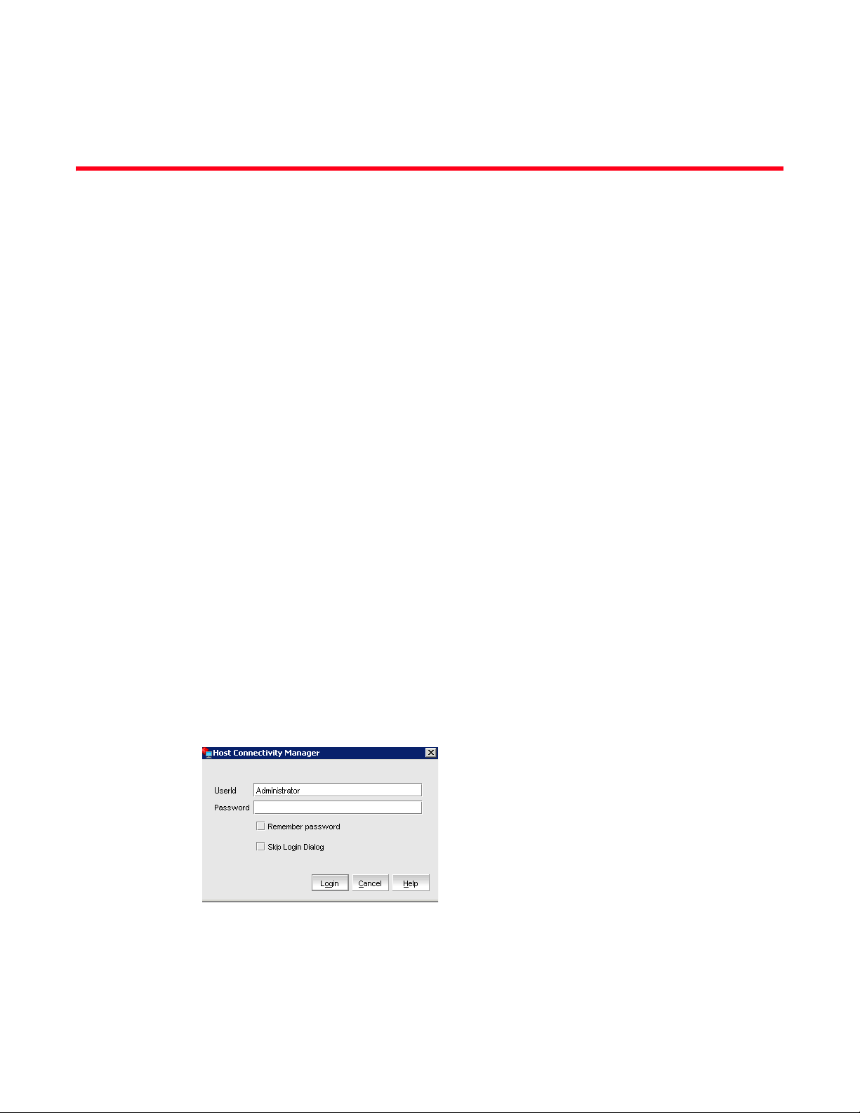
Figure 1 shows the screen that appears when HCM software is first launched.
FIGURE 1 HCM Login dialog box
The factory default user ID and password are Administrator and password. After you log in for the
first time, you should change the default password to a new one using the HCM GUI.
Brocade Adapters Administrator’s Guide 5
53-1001583-01
Page 20

HCM software launch
2
Launching the application on Linux platforms
After installing the HCM software, locate Brocade HCM on the Linux platform.
• If using a GNOME shell, double-click the Host_Connectivity_Manager icon to launch the
application.
• If using a KDE shell, click the Host_Connectivity_Manager icon to launch the application.
OR
Start the application from the command prompt using the following commands:
suse116208:~ # cd /opt/brocade/adapter/client
suse116208:<installed directory>/adapter/client #
./Host_Connectivity_Manager
Remember password
The Login dialog has a check box to remember the password. If you check the Remember password
check box, you do not need to enter the password the next time you launch the application.
Skip login
Take one of the following actions to manage the Skip Login feature.
• Enable Skip Login by checking the Skip Login Dialog check box.
If the Skip Login check box is checked, it automatically disables the Remember password
option.
• Disable Skip Login by setting hba-application.skip-login=false in the
/data/HBAApplication.properties file.
• Select the Skip Login check box if you do not want the Login dialog box to appear the next time
the application is started.
Changing an HCM application password
You can change the default password of the application to a different password using the Change
HCM Password dialog box.
Note the following when you change a password:
• You must validate your user identity by supplying your old password before you can change to a
new password. The new password must be different than the old password.
• The password can begin with an alphabetic, numeric, or special character.
• The default minimum and maximum length of the password is 8 and 64 characters. You can
configure the password length in the HBAApplication.properties file:
# min chars for the application password
password_min=8
#max chars for the application password
password_max=64
• The password is encrypted and stored in the noitacitnehtua.properties file.
6 Brocade Adapters Administrator’s Guide
53-1001583-01
Page 21
HCM software launch
NOTE
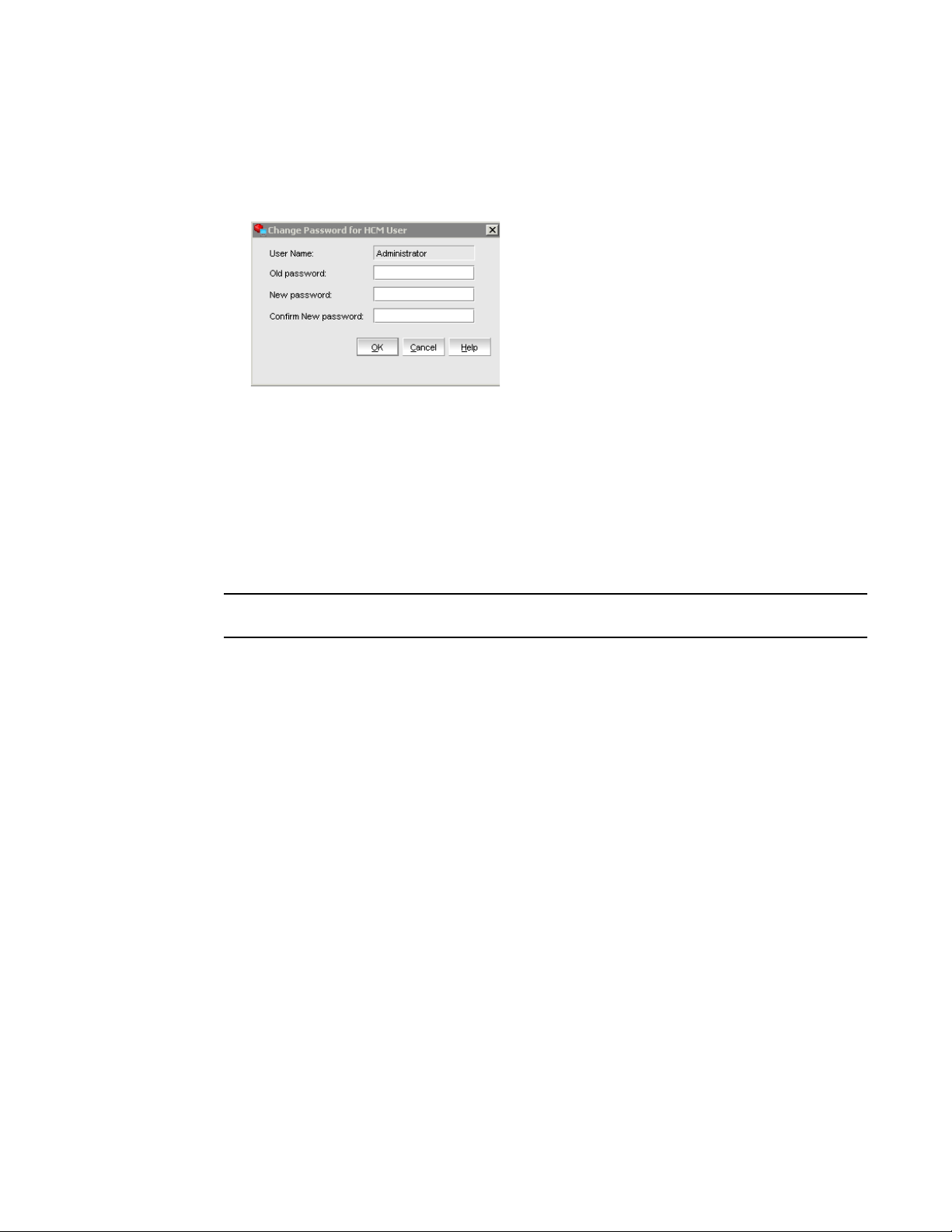
1. From the Host Connectivity Manager, select Configure > Change Password > Change Password
for HCM User.
The Change HCM Password dialog box, shown in Figure 2, displays.
2
FIGURE 2 Change HCM Password dialog box
2. Type the current password for the account. The default user name and password are
Administrator and password.
3. Type the new password of the account.
The new password must have at least one character different from the old password.
4. Retype the new password in the Confirm New password field.
5. Click OK.
Both the user name and passwords are case-sensitive.
Changing an HCM agent password
You can change the default password of the agent to a different password using the Change HCM
Agent Password dialog box.
Note the following when you change a password:
• You must validate your user identity by supplying your old password before you can change to a
new password. The new password must be different than the old password.
• The password can begin with an alphabetic, numeric, or special character.
• The default minimum and maximum length of the password is 8 and 64 characters. You can
configure the password length in the HBAApplication.properties file:
# min chars for the application password
password_min=8
#max chars for the application password
password_max=64
• The password is encrypted and stored in the noitacitnehtua.properties file.
Brocade Adapters Administrator’s Guide 7
53-1001583-01
Page 22
HCM software launch
NOTE
2
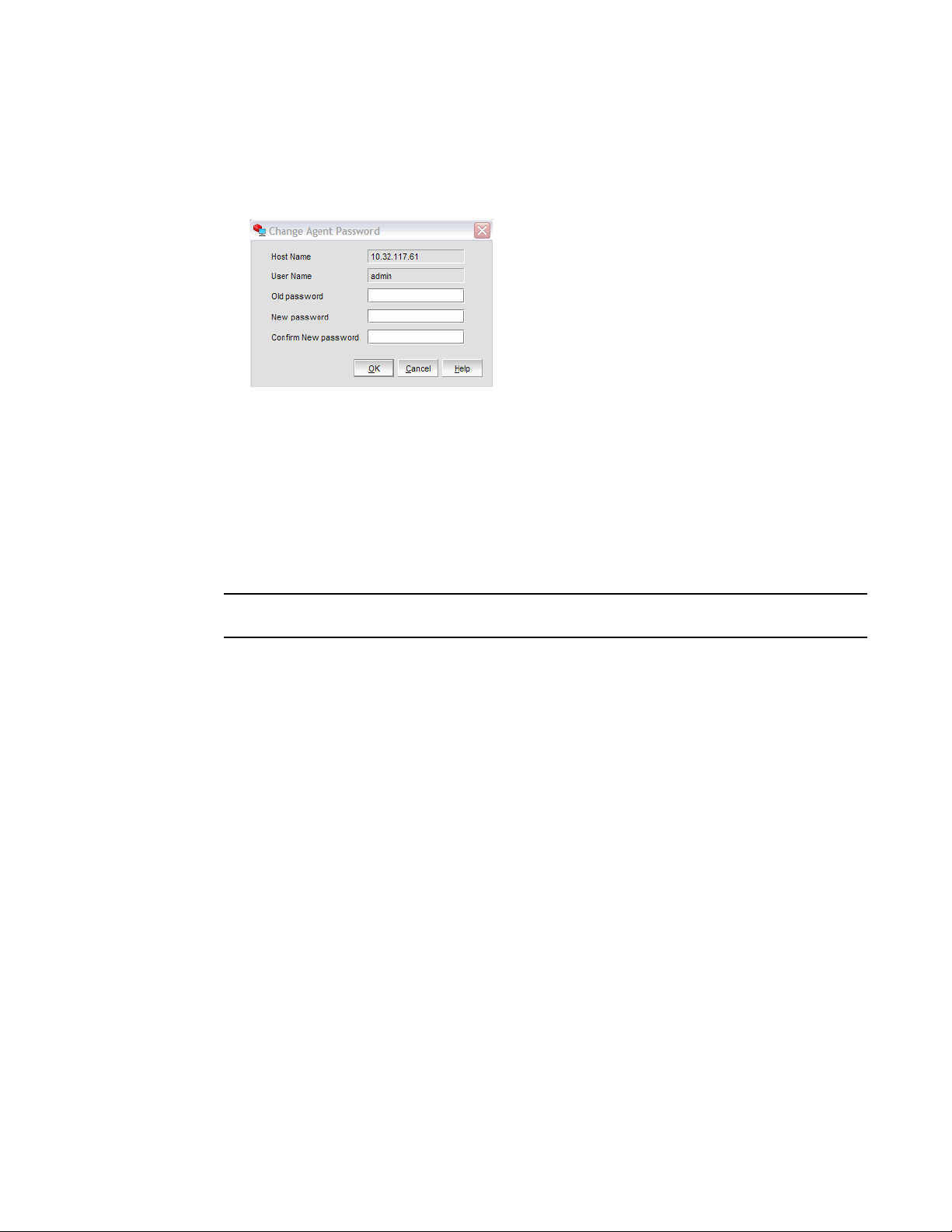
1. From the Host Connectivity Manager, click Configure > Change Password > Change Agent
Password.
The Change HCM Agent Password dialog box, shown in Figure 3, displays.
FIGURE 3 Change HCM Agent Password dialog box
2. Type the current password for the account. The default user name and password are admin
and password.
3. Type the new password of the account.
The new password must have at least one character different from the old password.
4. Retype the new password in the Confirm New password field.
5. Click OK.
Both the user name and passwords are case-sensitive.
8 Brocade Adapters Administrator’s Guide
53-1001583-01
Page 23

Software downgrade using Adapter Software Installer
Software downgrade using Adapter Software Installer
Although driver and HCM downgrades are not supported, the following procedures are
recommended for downgrading between versions 2.1, 2.0, and 1.1 of the Brocade adapter
software. If you are not downgrading previous software versions, proceed to HCM software launch.
Downgrading HCM and driver or HCM only
To downgrade HCM and adapter drivers or HCM only, follow these steps, which are detailed in the
following designated sections of the Brocade Adapters Installation and Reference Manual.
1. Uninstall HCM and drivers or HCM only using procedures detailed under "Software removal
using Adapter Software Uninstaller."
2. When a message box displays asking to back up the HCM configuration, click Yes and proceed
with the software removal. Refer to "HCM configuration data."
3. Install the desired version of the software using "Using the Adapter Software Installer."
When the "Found Backed up data" message displays prompting you to restore old
configurations, select restore the data and continue with the installation.
2
Downgrading driver only
Uninstall existing drivers using procedures under "Software removal using Adapter Software
Uninstaller" in the Brocade Adapters Installation and Reference Manual.
Install new drivers using procedures under "Using the Adapter Software Installer" in the Brocade
Adapters Installation and Reference Manual.
HCM configuration data
HCM configuration data is compatible between version 2.1, 2.0, 1.1, and 1.0 of the Brocade
adapter software. Configuration data that is backed up when prompted during software removal
with the Adapter Software Uninstaller and when using the HCM Backup dialog box includes the
following:
The following application configuration files are backed up in the data directory:
• HBAApplication.properties
• SetupDiscovery.properties
• HbaAliasdb.properties
• log4j.xml
• noitacitnehtua.properties
• Syslog.properties
• Logging.properties
Brocade Adapters Administrator’s Guide 9
53-1001583-01
Page 24

Software downgrade using Adapter Software Installer
NOTE
2
Backing up data after an uninstall
If you uninstall the Brocade HCM software, you are prompted to back up the application
configuration data that was created during installation. Be sure to back up configuration data when
the backup message displays during uninstallation. You can perform a backup on an as-needed
basis.
Following are default locations for HCM configuration data.
• Versions 1.1.0.8 and above - <user home>\HCM\data
• Versions 1.1.0.6 and below - <installation location>\FC HBA\data
To restore the backed-up configuration data when you re-install the HCM, you must manually
overwrite the new data directory contents with the backed-up data. This restores your previous
settings.
Data restoration
You can use the Restore Data dialog box to restore data that has been previously backed up. The
Host Connectivity Manager (HCM) stores the location and version details of the most recently-taken
backed up data and automatically points to the location of the data.
Use HCM 2.1 or later to restore backed up data. HCM 2.0 and earlier versions do not support the
Restore Data feature.
The following data is restored:
• HBA application configuration data (HBAApplication.properties)
• HCM user authentication data (noitacitnehtua.properties)
• Alias Configuration data (HbaAliasdb.properties)
• Setup Discovery data (SetupDiscovery.properties)
• Syslog data (Syslog.properties)
• HCM Logging data (logging.properties and log4j.xml)
• SupportSave
Restoring backed up data
You must use HCM 2.1 or later to restore backed-up data.
1. Select the host, an HBA, or a port from the device tree.
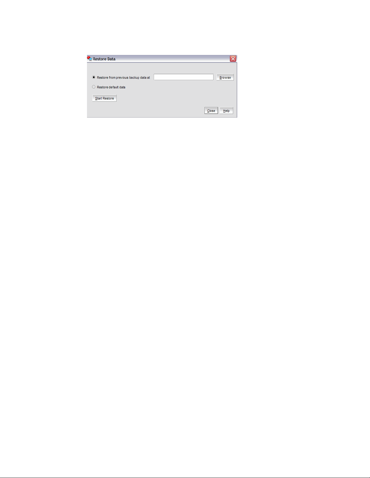
2. Select Tool > Restore Data from the main menu.
The Restore Data dialog box, shown in Figure 4, displays.
10 Brocade Adapters Administrator’s Guide
53-1001583-01
Page 25
Software downgrade using Adapter Software Installer
2
FIGURE 4 Restore Data dialog box
3. Click the Restore from previous backup data at button, and then click Browse and navigate to
where the last backed up file resides.
OR
Click the Restore default data button. If you click this button, the Browse field is grayed out and
the last restored data file is automatically retrieved.
4. Click Start Restore.
5. Restart the HCM application for the restoration to take effect.
The backed up data that you selected is restored.
Brocade Adapters Administrator’s Guide 11
53-1001583-01
Page 26
HCM main window
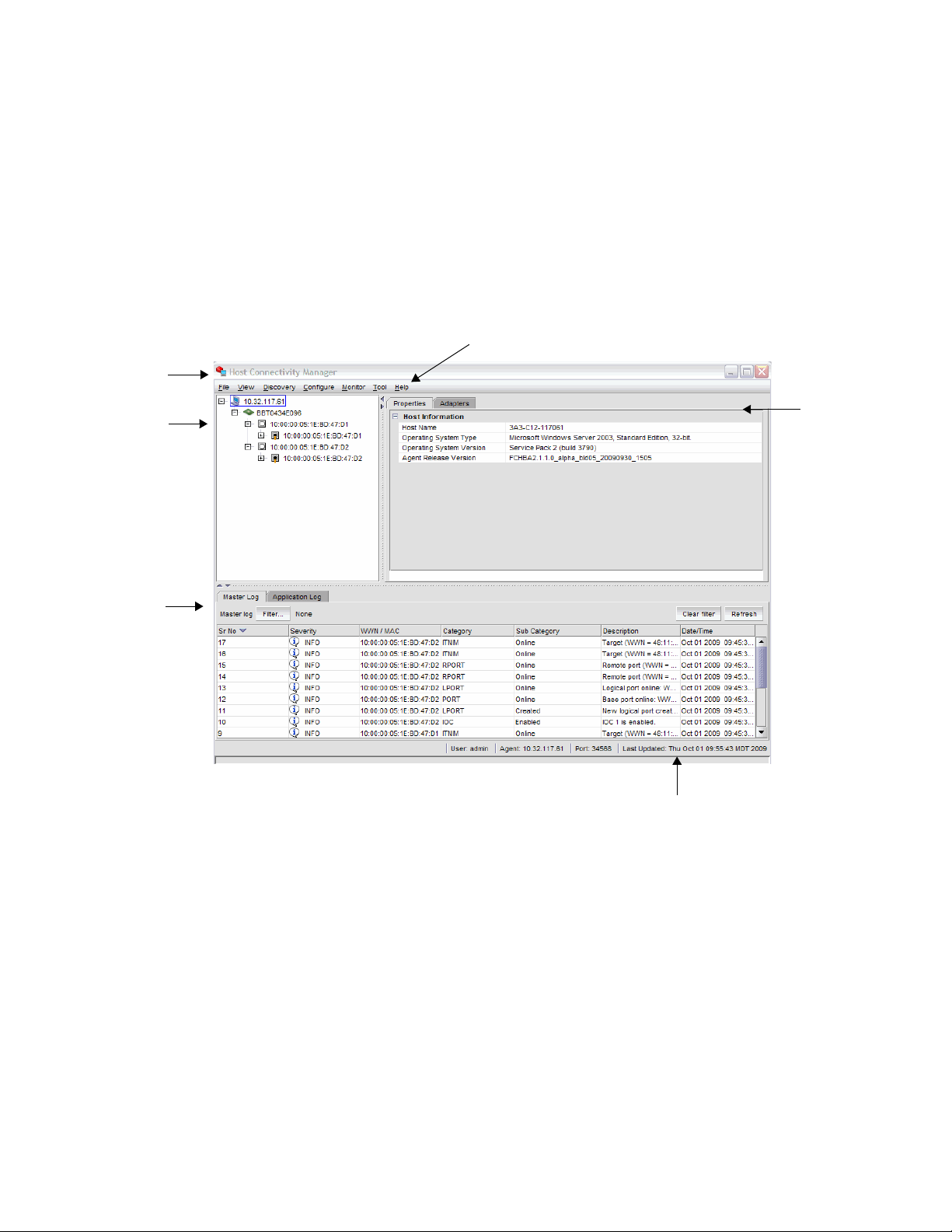
1. Menu bar
2. Device tree window
3. Master Log
4. Online help
5. System information
1.
2.
3.
6. Context view
5.
4.
6.
2
HCM main window
From the Host Connectivity Manager main window, shown in Figure 5, you can manage all the
adapters installed in this computer. Alternatively you can manage adapters installed in remote
computers, if the computers are networked. Only one host can be managed at a time; multiple host
management is not supported.
Refer to the Brocade Adapters Installation and Reference Manual for instructions on how to install
both the driver and GUI, the driver only, or the GUI only.
FIGURE 5 Host Connectivity Manager main window
12 Brocade Adapters Administrator’s Guide
53-1001583-01
Page 27
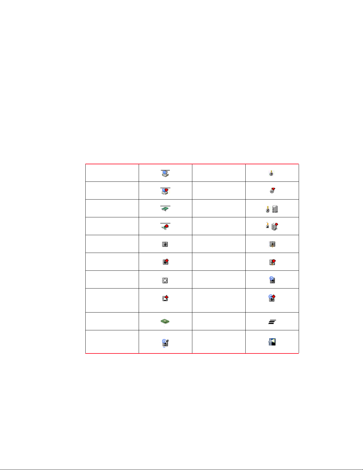
Legend Help menu
To display the HCM product icons and the event severity icons, select Help > Legends from the
Host Connectivity Manager.
HCM product icons
On the left side of the Host Connectivity Manager, there is a navigation tree for representing the
managed host with adapters and ports. Each tree node has an icon to represent the type of node.
If the operational status is offline, link-down, or error, a small red diamond appears on the upper
right corner of the icon.
Tab le 4 shows the product icons that represent the components that HCM manages.
TABLE 4 HCM product icons
Host (agent up) Remote Port (Initiator)
Host (agent down) Remote Port (Initiator)
online
offline
Legend Help menu
2
HBA online Remote Port (Target)
online
HBA offline Remote Port (Target)
offline
Port (with SFP) link up Base Port (link up)
Port (with SFP) link
down
Port (without SFP) link
up
Port (without SFP) link
down
Mezzanine card LUN
Pre-boot configured
device
Base Port (link down)
Virtual Port (online)
Virtual Port (offline)
Beacon Status
Brocade Adapters Administrator’s Guide 13
53-1001583-01
Page 28
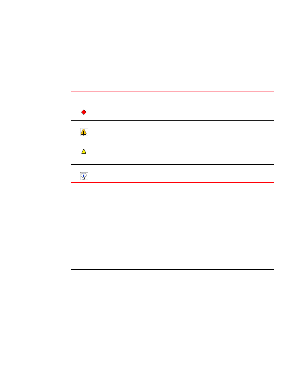
2
NOTE
Discovery
Event severity icons
Tab le 5 describes the icons that represent the four event types. Event filtering enables you to block
events based on user-defined criteria (severity or type of log). Events that have been filtered out do
not appear in the Master Log, For information about how to filter events, see “Filtering event log
entries” on page 64.
TABLE 5 HCM Master Log icons
Icon Description
Critical-level messages indicate that the software has detected serious problems that will
eventually cause a partial or complete failure of a subsystem if not corrected immediately; for
example, a power supply failure or rise in temperature must receive immediate attention.
Major messages represent conditions that do not impact overall system functionality significantly.
For example, timeouts on certain operations, failures of certain operations after retries, invalid
parameters, or failure to perform a requested operation.
Minor messages highlight a current operating condition that should be checked or it might lead to
a failure in the future. For example, a power supply failure in a redundant system relays a warning
that the system is no longer operating in redundant mode and that the failed power supply needs
to be replaced or fixed.
Discovery
Information-level messages report the current non-error status of the system components; for
example, the online and offline status of a fabric port.
Discovery enables you to contact the adapters present in a specified host in your SAN. The setup
discovery profile is saved in the SetupDiscovery.properties file to remember the history of
each host and related attributes of discovered hosts.
When you log in to HCM, the specified host is automatically contacted (discovered) and displayed
on the navigation tree. By default, the local host is automatically contacted (discovered) and
displayed on the navigation tree. When you configure and turn on discovery, the application
discovers Brocade adapters in that host, connected to the SAN.
The HCM application enables you to discover Brocade adapters, ports, virtual ports, remote ports,
and LUNs using out-of-band discovery only.
14 Brocade Adapters Administrator’s Guide
53-1001583-01
Page 29
Discovery
NOTE
NOTE
2
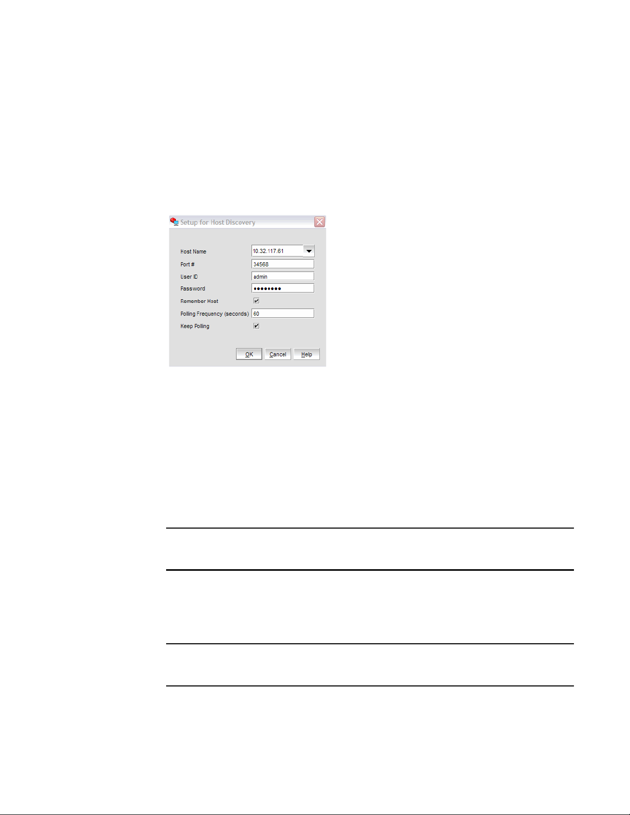
Setting up out-of-band discovery for an adapter
When performing out-of-band discovery, you are managing the adapter remotely. The application
connects to the agent running on the host server over the IP network and product information is
copied back from the Brocade adapter to the server. If you do not configure the application to
directly discover the devices, the connections and attached devices may not display correctly.
1. From the Host Connectivity Manager, click Discovery > Setup.
The Setup for Discovery dialog box, shown in Figure 6, displays.
FIGURE 6 Setup for Discovery dialog box
2. From the Host Name list, select the host name from where you will discover the adapter.
For the first time, the Host Name list will contain only the Local host. You must specify the host
name or the IP address for discovering the remote servers. Only previously-discovered servers
are available in the Host Name list.
3. Type the port number in the Port Number text box. The default is 34568.
4. Type in the user ID and password that will authenticate the SAN product with the agent. The
default user ID and password are admin/password.
It is recommended you change the agent password on the host for security reasons.
Click the Remember Host check box if you do not want to type it in each time you set up
discovery.
5. In the Polling Frequency (seconds) text box, specify the value for how frequently the application
has to poll for newly discovered devices.
All parameters related to the adapters that are installed in that server are refreshed each time
the poll occurs.
If the Keep Polling check box is checked, polling occurs after the specified polling interval. If
the check box is not checked, polling stops.
6. Click OK.
Brocade Adapters Administrator’s Guide 15
53-1001583-01
Page 30

Logging off HCM
2
Logging off HCM
End the HCM session using one of the following methods:
• From the Host Connectivity Manager, click File > Exit.
• Click the X in the upper-right corner of the HCM window to close it.
16 Brocade Adapters Administrator’s Guide
53-1001583-01
Page 31

Chapter
NOTE
NOTE
Host Configuration
In this chapter
•Host security authentication. . . . . . . . . . . . . . . . . . . . . . . . . . . . . . . . . . . . . . 17
•Buffer credits . . . . . . . . . . . . . . . . . . . . . . . . . . . . . . . . . . . . . . . . . . . . . . . . . . 20
•Basic port configuration . . . . . . . . . . . . . . . . . . . . . . . . . . . . . . . . . . . . . . . . . 20
•Boot over SAN . . . . . . . . . . . . . . . . . . . . . . . . . . . . . . . . . . . . . . . . . . . . . . . . . 28
•Virtual port configuration . . . . . . . . . . . . . . . . . . . . . . . . . . . . . . . . . . . . . . . . 32
•HCM logging levels . . . . . . . . . . . . . . . . . . . . . . . . . . . . . . . . . . . . . . . . . . . . . 34
•Advanced port configuration. . . . . . . . . . . . . . . . . . . . . . . . . . . . . . . . . . . . . . 35
•Name configuration. . . . . . . . . . . . . . . . . . . . . . . . . . . . . . . . . . . . . . . . . . . . . 37
•NPIV . . . . . . . . . . . . . . . . . . . . . . . . . . . . . . . . . . . . . . . . . . . . . . . . . . . . . . . . . 44
Host security authentication
3
Use the HCM GUI or the Brocade command line utility (BCU) to display the authentication settings
and status. There are five well-known DH groups; however, only DH-CHAP group 0, called NULL DH,
is supported in this release.
Security authentication is not supported on Solaris platforms.
Configuring security authentication using HCM (Host and HBA)
You can access the Fibre Channel Security Protocol Configuration dialog box by selecting the Host,
an HBA, or an HBA port from the device tree.
Fibre Channel Security Protocol (FC-SP) is not available for Solaris platforms.
1. Select the appropriate device based on how you want to configure security authentication:
• From the host level, select the host from the device tree.
• From the HBA level, select the adapter from the device tree.
• From an HBA port, select a port from the device tree.
Brocade Adapters Administrator’s Guide 17
53-1001583-01
Page 32

Host security authentication
3
2. Select Configure > Authentication from the main menu, or perform the appropriate following
step to open the security authentication dialog box:
• From the host level, right-click the host and select Authentication from the list.
The Fibre Channel Security Protocol Configuration (host level) dialog box displays, as
shown in Figure 7.
• From the adapter level, right-click the adapter and select Authentication from the list.
The Fibre Channel Security Protocol Configuration (adapter level) dialog box displays. This
dialog box is identical to the Fibre Channel Security Protocol Configuration (host level)
dialog box.
• From the adapter port level, right click a port and select FC-SP > Authentication from the
list.
The Fibre Channel Security Protocol Configuration dialog at the host level displays.
FIGURE 7 Fibre Channel Security Protocol Configuration - host-level dialog box
18 Brocade Adapters Administrator’s Guide
53-1001583-01
Page 33

Host security authentication
3. Configure the following parameters on the Port Security Authentication tab:
a. Select the Enable Authentication check box to enable or disable the authentication policy.
If authentication is enabled, the port attempts to negotiate with the switch. If the switch
does not participate in the authentication process, the port skips the authentication
process.
b. Type and retype the secret.
The maximum length of the secret is 63 bytes. The default secret for each interface is its
port world wide name (PWWN) without the colons; for example, 0102030405060708.
Select the algorithm type from the list:
• MD5 - A hashing algorithm that verifies a message’s integrity using Message Digest
version 5.
• SHA1 - A secure hashing algorithm that computes a 160-bit message digest for a data
file that is provided as input.
• MD5SH1 - Similar to the MD5 hashing algorithm, but used for DH-CHAP
authentication.
• SHA1MD5 - Similar to the SHA1 hashing algorithm, but used for DH-CHAP
authentication.
3
c. Select DHNULL as the group value (this is the only group that is supported).
4. Click Apply to apply the changes.
5. Click OK to save the changes and close the dialog box.
Configuring security authentication using the BCU
Enter the following commands to display or configure security authentication for the ports:
• bcu auth --algo <port_id> <md|sha1|ms|sm>
• bcu auth --policy <port_id> {on|off}
• bcu auth --secret <port_id> “secret_string”
• bcu auth --show <port_id>
• bcu auth --stats <port_id>
• bcu auth --statsclr <port_id>
Refer to “auth” on page 128 for details about these commands.
Brocade Adapters Administrator’s Guide 19
53-1001583-01
Page 34

Buffer credits
3
Buffer credits
Buffer-to-buffer credit flow control is implemented to limit the amount of data a port sends, based
on the number and size of the frames sent from that port. This scheme allows Fibre Channel to be
self-throttling, thereby allowing it to establish a reliable connection without the need to
accommodate dropped frames due to congestion. Buffer credit limits between each device and the
fabric are communicated at the time of fabric login. One buffer credit allows a device to send one
frame of data (typically 1 or 2 KB). Buffer credits cannot be configured on an adapter.
The default BB Credit is 1. The baseline for the calculation is one credit per kilometer at 2 Gbps.
This yields the following values for 10 km:
• 5 credits per port at 1 Gbps
• 10 credits per port at 2 Gbps
• 20 credits per port at 4 Gbps
• 40 credits per port at 8 Gbps
Refer to the “Extended Fabrics concepts and planning” section of the Fabric OS Administrator’s
Guide for detailed information about buffer credits.
Basic port configuration
For each port, you can configure the following parameters using the Basic Port Configuration dialog
box, the Brocade Command Line utility (BCU), or both. Table 6 lists the features and configuration
options.
TABLE 6 Basic port configuration options
Port configuration parameter
Port logging level Yes Yes “Port logging level”
Configure speed Yes Yes “Port speed”
Frame data field size Yes Yes “Frame data field size”
Persistent Binding
Note: The persistent binding option is
available on Windows platforms only.
QoS Yes Yes “QoS”
Path Time Out
Note: Path time out value (pathtov) is
valid for firmware versions 2.0 and
higher. It is not supported on the
Solaris operating system.
Configurable using
HCM
Yes Yes “Persistent binding”
Yes Yes “Path time out”
Configurable using
the BCU For more information
Tar get Ra te Lim it ing Yes Yes “Target rate limiting”
20 Brocade Adapters Administrator’s Guide
53-1001583-01
Page 35

Basic port configuration
NOTE
3
Opening the Basic Port Configuration dialog box
You can access the Basic Port Configuration dialog box, shown in Figure 8, by selecting the Host,
an HBA, or an HBA port from the device tree.
There are slight changes in HCM’s Basic Port Configuration dialog box, depending on the operating
system.
1. Select a device from the device tree.
2. Select Configure > Basic Port Configuration from the main menu.
The Basic Port Configuration dialog box displays.
FIGURE 8 Basic Port Configuration dialog box - Windows, Linux, and VMware
Port logging level
The number of messages logged by the host depends on the predetermined logging level. Although
the adapter might generate many messages, only certain types of messages are logged based on
the specified logging level.
Brocade Adapters Administrator’s Guide 21
53-1001583-01
Page 36

Basic port configuration
3
Configuring the port logging level using HCM
1. Select Configure > Basic Port Configuration from the Host Connectivity Manager.
The Basic Port Configuration dialog box displays.
2. Select a value from the Port Logging Level list.
Supported values are Log Critical, Log Error, Log Warning, Log Info, and Log Invalid.
3. Click Apply to apply the changes.
4. Click OK to save the changes and close the window.
Configuring the port logging level using the BCU
Enter the following command to set the logging level on the port.
bcu log --level <port_id> [<level>] [-m <fw|ha1|fcs|drv|aen|all>]
Refer to “log” on page 147 for details about this command.
Port speed
Port speed is the maximum amount of data that can pass through the port at a given second. The
unit of measurement is in gigabits per second (Gbps). The available speed options depend on the
HBA’s speed and the port’s SFP. Auto-negotiate is the recommended setting and it is the default.
Speed options for the 4 Gbps HBA (425 and 415) and the mezzanine card (804) are 1 Gbps,
2 Gbps, 4 Gbps, and 8 Gbps. The 8 Gbps HBA supports the 1 Gbps speed at the driver level, but it
does not support 1 Gbps in a BIOS/BOS configuration.
Configuring the port speed using HCM
1. Select Configure > Basic Port Configuration from the Host Connectivity Manager.
The Basic Port Configuration dialog box displays.
2. Select a value from the Configured Speed list.
3. Click Apply to apply the changes.
A port disable/enable configuration dialog box displays, confirming the configured speed,
which will take effect when the port is disabled or enabled.
4. Click Yes to continue, or No to cancel the operation.
5. Click OK to close the window.
22 Brocade Adapters Administrator’s Guide
53-1001583-01
Page 37

Basic port configuration
NOTE
3
Configuring the port speed using the BCU
Enter the following command to set the port speed.
bcu port --speed <port_id> [<speed>]
Refer to “port” on page 151 for details about this command.
Frame data field size
Buffer credits determine the maximum amount of frame data. If the number of buffer credits is not
large enough to handle the link distance and speed, performance can be severely limited.
See “Buffer credits” on page 20 for information about buffer credits.
Specifying the maximum frame size using HCM
1. Select Configure > Basic Port Configuration from the Host Connectivity Manager.
The Basic Port Configuration dialog box displays.
2. Select the frame size from the Frame Data Field Size list. Options include 512, 1024, 2048,
2112 Mbps and auto. The default value is 2112.
3. Click Apply to apply the change.
4. Click OK to close the window.
Configuring the frame data field size using the BCU
The dfsize command sets the ports maximum receive data field size. If you do not specify a value,
the driver default receive buffer size displays, which is 2112.
The new receive data field size takes effect when the port is re-enabled.
Enter the following command to set the frame data field size.
bcu port --dfsize <port_id> [<dfsize>]
Refer to “port” on page 151 for details about this command.
Brocade Adapters Administrator’s Guide 23
53-1001583-01
Page 38

Basic port configuration
3
Persistent binding
Persistent binding enables you to permanently assign a system SCSI target ID to a specific FC
device. Persistent binding can be achieved by binding to world wide port name (WWPN), world wide
node name (WWNN), or device ID (DID).
You can access the Persistent Binding dialog box by selecting the Host or an HBA from the device
tree.
Enabling and disabling persistent binding using HCM
Persistent binding can be enabled or disabled from the HCM GUI using the following steps:
1. Launch the Basic Port Configuration dialog box at the port level.
2. Check or uncheck the Persistent Binding check box in the Basic Port Configuration dialog box.
Enabling and disabling persistent binding using the BCU
Target persistent binding enables target port world wide name binding to a persistent target ID for
the OS stack. Using the -list operand, you can query the list of mappings from the persistent binding
module.
Enter the following commands to configure target persistent binding:
• bcu pbind --list <port_id> [<pwwn>]
• bcu pbind --clear <port_id>
Refer to “pbind” on page 150 for details about this command.
24 Brocade Adapters Administrator’s Guide
53-1001583-01
Page 39

Basic port configuration
NOTE
3
QoS
Quality of Service (QoS) works in conjunction with the QoS feature on Brocade switch F_Ports. The
Fabric operating system (FOS) provides a mechanism to assign traffic priority (high, medium, or
low) for a given source and destination traffic flow. By default, all flows are marked as medium.
This feature is supported only on 8 Gbps HBA ports installed on specific switch models that use
Fabric OS 6.2 and later. The following licenses need to be installed on the switch connected to each
HBA port (edge switch):
• Adaptive Networking (AN) license
• Server Application Optimization (SAO) license
To determine if these licenses are installed on the connected switch, execute the Fabric OS
licenseshow command. Refer to the Fabric OS Administrator’s Guide for detailed information about
QoS.
Configuring QoS on the switch side using the BCU
On the switch side, you can create QoS zones using the PWWNs that correspond to devices in a
source/destination traffic flow. You need a Server Application Optimization (SAO) license installed
on the switch to enable QoS. In addition, an Adaptive Networking (AN) license is required on the
switch to enable QoS on the switch ports.
You enable or disable QoS settings on ports with the portCfgQos command. Refer to the Fabric OS
Administrator’s Guide for details about this command on the switch side.
Configuring QoS on the HBA side using the BCU
There are three possible QoS states:
• Enabled, online - QoS is established with the switch.
• Enabled, offline - QoS negotiation failed and QoS was not established with the switch. Possible
reasons for failure could be the license is not installed on the switch or QoS is not enabled on
the port.
• Disabled.
You must first enter the bcu port --disable <port_id> command, followed by the
bcu port --enable <port_id> command, before the bcu qos --enable or
bcu qos --disable commands take effect.
Brocade Adapters Administrator’s Guide 25
53-1001583-01
Page 40

Basic port configuration
3
Enter the following commands to enable or disable QoS support on the HBA side:
• bcu qos --enable <port_id>
• bcu qos --disable <port_id>
• bcu qos --query <port_id>
• bcu qos --stats <port_id>
• bcu qos --statsclr <port_id>
Refer to “qos” on page 155 for details about this command.
Path time out
With path time out values (TOV), you can either force an immediate failover (by setting the TOV to 0)
or you can specify a delay in seconds (1-60 seconds). The default TOV is 30.
Specifying path time out using HCM
1. Select Configure > Basic Port Configuration from the Host Connectivity Manager.
The Basic Port Configuration dialog box displays.
2. Type a value in the Path Time Out field.
3. Click OK to close the window.
Specifying path time out using the BCU
Enter the following command to specify the optional path time out value in seconds (1 to 60). The
default TOV is 10 seconds. A value of 0 is not allowed from the BCU.
bcu fcpim --pathtov <port_id> tov
Refer to “fcpim” on page 143 for details about this command.
Target rate limiting
The target rate limiting feature is used to minimize congestion at the adapter port caused by a slow
drain device operating in the fabric at a slower speed. A remote port’s operating speed is
determined from the fabric, and then the information is used to throttle the transmitted traffic rate
to that remote port. Traffic destined to the remote port is limited to its current operating speed.
Limiting the data rate to slower targets ensures that there is no buffer-to-buffer credit
back-pressure between the switch due to a slow-draining target.
26 Brocade Adapters Administrator’s Guide
53-1001583-01
Page 41

Basic port configuration
NOTE
3
Enabling and disabling rate limiting on the adapter side using HCM
Target rate limiting is supported only when the adapter port is connected to the fabric. Therefore,
target rate limiting is not supported when the port is directly connected with another device.
1. Select Configure > Basic Port Configuration from the Host Connectivity Manager.
The Basic Port Configuration dialog box displays.
2. Enable the Target Rate Limiting feature by clicking the corresponding check box.
3. Select the default rate limit from the list. Options include 1 Gbps, 2 Gbps, and 4 Gbps; the
default is 2 Gbps.
4. Click OK to close the window.
Enabling and disabling rate limiting on the adapter side using the BCU
Enter the following commands to enable or disable rate limiting on the adapter side:
You must first enter the bcu port --disable <port_id> command, followed by the
bcu port --enable <port_id> command, before the bcu ratelim --enable or
bcu ratelim --disable commands take effect.
• bcu ratelim --enable <port_id> ]
• bcu ratelim --disable <port_id>
• bcu ratelim --query <port_id>
• bcu ratelim --defspeed <port_id> [<1|2|4>]
Refer to “ratelim” on page 156 for details about this command.
Brocade Adapters Administrator’s Guide 27
53-1001583-01
Page 42

Boot over SAN
NOTE
3
Boot over SAN
Boot over SAN configuration using the Basic Port Configuration dialog box is enabled on all
platforms if the HCM version is 1.1 or higher.
The Boot over SAN feature allows you to target remote boot devices (LUNs on SAN storage arrays)
from which to boot the host system. When the host’s operating system and adapter driver are
installed on the remote device, the adapter BIOS and user-configurable boot instructions stored in
adapter flash memory allow the host to boot from the device.
Various operating systems require you to follow specific guidelines to enable servers to boot from a
SAN. Understanding these requirements is key to a successful deployment of a boot over SAN
environment.
Boot LUNs are identified to adapter ports using the BIOS Configuration Utility and BCU commands.
These utilities also allow you to enable or disable BIOS for booting the host system over SAN, set
boot options, and set the port speed. Refer to the Brocade Adapters Installation and Reference
Manual for instructions.
BIOS boot over SAN provides the ability for x86 and x86_64 systems to perform booting of the OS
installed on the SCSI disk connected over the Fibre Channel SAN.
The maximum number of supported adapters is limited to 16 and the maximum targets and LUNs
that are displayed during discovery is limited to 256.
After you have configured boot devices using the BIOS Configuration Utility, you can enable or
disable BIOS for Boot over SAN, set boot options, and set port speed using the HCM GUI. All
configuration information is stored in flash memory.
Configuring Boot over SAN
The boot-LUN table lists the vendor information, LUN capacity, and whether the LUNs are
accessible. These fields are not editable.
You can access the Boot-over-SAN dialog box by selecting the Host, an adapter or a physical port
from the device tree.
1. Select Configure > Basic Port Configuration from the Host Connectivity Manager.
The Basic Port Configuration dialog box displays.
2. Click the Boot-over-SAN tab.
The Boot-over-SAN dialog box, shown in Figure 9, displays.
28 Brocade Adapters Administrator’s Guide
53-1001583-01
Page 43

FIGURE 9 Boot-over-SAN dialog box
Boot over SAN
3
3. Click the BIOS Enable check box to enable Boot over SAN.
4. From the Boot Option list, select one of the following:
• Auto Discovered from Fabric - Enables Boot over SAN using boot LUN information stored in
the fabric. This is the default setting.
• First Visible LUN - Enables Boot over SAN from the first discovered LUN in the SAN.
• User Configured LUNs - Allows the user to select and prioritize the remote target and LUN
for booting over SAN.
5. Select the Boot Device Port WWN row in the table, then click the up and down arrows to move
the row up or down in the table. The host will attempt to boot from the first LUN in the table,
and then move on to succeeding LUNs.
• You can delete a row using the Delete button under the arrows.
• Click the Boot Device Port WWN and LUN fields to physically enter boot LUNs to the table.
These LUNs must be visible to the adapter to be accessible as boot LUNs.
6. Click OK.
The Vendor Info, LUN Capacity, and Accessible status that correspond to the selected boot
device and LUN display automatically.
Brocade Adapters Administrator’s Guide 29
53-1001583-01
Page 44

3
Boot over SAN
Pre-boot configuration
Any parameters flagged with pre-boot were configured using a blade system management
application. You cannot use HCM to create or modify a pre-boot configuration. If the port has been
pre-boot enabled:
• The BIOS Enable option is disabled.
• The pre-boot configured LUNs in the LUN column are displayed as <LUN wwn> (Pre-boot), as
shown in Figure 9. The maximum number of user-configured LUNs supported is four, and the
maximum number of pre-boot-configured LUNs is eight.
• The configuration changes take affect after the next reset.
Configuring fabric-based boot LUN discovery
Use the following steps to configure fabric-based boot LUN discovery.
1. Set the adapter’s BIOS configuration to auto-discovery using one of the following interfaces:
• Brocade BIOS Configuration Utility
Adapter Settings > Boot LUN > Auto Discover
• HCM
Refer to “Configuring Boot over SAN” on page 28 for instructions.
• BCU
bios --enable <port_id> -o auto
2. Enter the following BCU command to provide the zone name and zone members to use as
operands in the Fabric OS zonecreate command.
bcu boot --blunZone -c <cfg> -p <port_wwn> -r <rport_wwn> -l <lun_id | lun#>
Refer to “boot” on page 133 for details about this command.
3. Configure the zone on the switch using the Fabric OS zoneCreate command. Refer to the
Brocade Adapters Installation and Reference Manual or the Fabric OS Administrator’s Guide
for more information about creating zones.
30 Brocade Adapters Administrator’s Guide
53-1001583-01
Page 45

Boot over SAN
3
Boot image update
You can update a boot image at the host level or at the adapter level.
At the host level, if the HCM version is lower than 2.1, the Upload Boot Image menu is enabled only
when one HBA is visible. If the agent version is 2.1 and higher, the Upload Boot Image menu is
always enabled if at least one adapter is visible and will update the image to all visible adapters.
Uploading the boot image using HCM
1. Download the boot code (brocade_adapter_boot_fw_v2-1-1-0) from www.brocade.com/hba to
a folder on your local drive.
2. Launch HCM.
3. Right-click a host or adapter from the device tree and select Upload Boot Image from the list.
• Right-clicking a host downloads the boot image to all adapters that are installed on the
host.
• Right-clicking an adapter downloads the boot image to the selected adapter only.
The Upload Boot Image dialog box displays.
4. Click the Browse button and navigate to the location of the boot image.
5. Select the boot image and click Open.
The selected file downloads. If an error occurs during the downloading process, an error
message displays.
Updating the boot image using the BCU
Enter the following command to update the boot image.
bcu boot --update [adapter_id] <image_file> [-a]
Refer to “boot” on page 133 for details about this command.
Brocade Adapters Administrator’s Guide 31
53-1001583-01
Page 46

Virtual port configuration
3
Virtual port configuration
Virtual ports (V_Ports) appear to the hosts as physical ports in the data network. One or more
virtual ports are assigned to each host, and a host can access storage at a virtual port only if the
virtual port has been assigned to the host.
Virtual port restrictions
• You cannot create a V_Port that already exists in the Names dialog box. If you need to re-create
a V_Port that has been deleted through an interface other than the currently-managing HCM or
the V_Ports deleted on Linux servers reboot, you must first manually remove the V_Port’s WWN
from the Names dialog box in HCM. If you do not manually remove the V_Port from HCM, an
error message displays that the V_Port already exists. See “Removing a name entry” on
page 40 for instructions on how to manually remove a V_Port.
• The HCM GUI should post an error message for duplicate VPorts (detected in the Vports.db file)
and prompt the user to remove the duplicate, but it does not. Duplicate world wide names are
not restricted when the BCU is used to create V_Ports. Do not use the BCU for virtual port
management, because it does not handle duplicate V_Port world wide names. Instead, use
only the HCM GUI to manage vPorts.
Creating a virtual port
You create virtual ports on HBA ports only; virtual ports are not supported on an adapter. Virtual
ports are not supported for VMware and Solaris agents.
1. Select a physical HBA port from the device tree.
2. Select Configure > Virtual Port > Create from the main menu.
OR
Right-click the physical port and select Virtual Port > Create from the list.
The Virtual Port Creation dialog box, shown in Figure 10, displays. The following fields are
system-generated:
• Physical port world wide name.
• Virtual port world wide name - This WWN must be unique.
• Virtual node world wide name - The system returns the default node WWN, which is the
physical port node WWN.
32 Brocade Adapters Administrator’s Guide
53-1001583-01
Page 47

Virtual port configuration
NOTE
NOTE
By default, the Use auto-generated check box is selected and the Generate Again button is
enabled. You can still edit the Virtual Port WWN field if Use auto-generated is selected.
FIGURE 10 Virtual Port Creation dialog box
3
3. (Optional). Provide a symbolic name for the virtual port.
4. (Optional). Provide an alias name for the virtual port. By creating an alias, you can assign a
familiar name to a device or group multiple devices into a single name. This can simplify
cumbersome data entry and allows an intuitive naming structure.
5. (Optional). Enter descriptive information about the virtual port into the Description field.
6. Click OK to apply the changes and close the window.
Deleting a virtual port
If the maximum number of virtual ports have already been created, the option to create virtual
ports using HCM is disabled.
Pre-boot-created virtual ports are not labeled. If the virtual port is pre-boot-created, the Delete check
box is disabled.
1. Select a virtual port from the device tree.
2. Select Configure > Virtual Port > Delete from the main menu.
OR
Right-click the virtual port and select Virtual Port > Delete from the list.
A warning message displays, asking for confirmation.
3. Click OK to continue.
The Virtual Port Deletion dialog box displays.
Brocade Adapters Administrator’s Guide 33
53-1001583-01
Page 48

HCM logging levels
3
FIGURE 11 Virtual Port Deletion dialog box
4. Click the check box that corresponds to one or multiple virtual ports you want to delete, and
click OK.
HCM logging levels
You can set the log level for the following modules:
• Agent communication log, where all messages are exchanged between the HCM GUI
application and the HCM agent.
• HCM debug log, where messages are logged locally.
If you do not set an HCM log level, DEBUG, which is the default, is used.
Configuring the HCM logging level using HCM
1. Select Configure >HCM Logging Levels from the Host Connectivity Manager.
The Configure HCM Logging Levels dialog box, shown in Figure 12, displays.
FIGURE 12 Configure HCM Logging Levels dialog box
2. From both the Agent Communication Log and the HCM Debug Log lists, select one of the
following:
• Tra ce
• Debug, the most verbose and the default
• Info
• Warning
• Error
• Fatal, which is the least verbose.
3. Click Apply to apply the change.
34 Brocade Adapters Administrator’s Guide
53-1001583-01
Page 49

Advanced port configuration
You can access the Advanced Port Configuration dialog box by selecting an HBA port from the
device tree.
For each port, you can configure the following parameters using the Advanced Port Configuration
dialog box, the Brocade Command Line utility (BCU), or both. Tab le 7 lists the features and
configuration options.
TABLE 7 Advanced port configuration options
Port configuration parameter Configurable using HCM Configurable using the BCU
Interrupt Control Coalesce Yes Yes
Interrupt Control Latency Yes Yes
Interrupt Control Delay Yes Yes
Opening the Advanced Port Configuration dialog box
1. Select an HBA port from the device tree.
Advanced port configuration
3
2. From the Host Connectivity Manager, select Configure > Port Configuration > Advanced.
The Advanced Port Configuration dialog box, shown in Figure 13, displays.
FIGURE 13 Advanced Port Configuration dialog box
Brocade Adapters Administrator’s Guide 35
53-1001583-01
Page 50

Advanced port configuration
NOTE
3
Interrupt Control Coalesce
Interrupt control coalescing allows the system to optimize CPU utilization by varying the number of
interrupts generated. Increasing the latency monitor timeout value should result in a lower
interrupt count and less CPU utilization, which may result in higher throughput.
You can configure the following interrupt control coalescing parameters per port:
• Interrupt delay time - The host interrupt generation is delayed by the specified duration to
• Interrupt latency timer - This value helps to minimize I/O latency by avoiding host interrupt
Configuring the Interrupt Control Coalesce using HCM
1. Select a port from the device tree.
coalesce multiple I/O interrupt events into one. Increasing this value results in fewer interrupts
per multiple interrupt events.
generation to have to wait until the interrupt delay has expired for an I/O throughput.
• From the Host Connectivity Manager, select Configure > Advanced Port Configuration.
The Advanced Port Configuration dialog box displays.
OR
• Right-click a port and select Port Configuration > Advanced.
2. Set the latency and delay values:
• Select On from the Interrupt Control Coalesce list.
Interrupt Control Coalesce is On by default.
• Specify the latency monitor timeout value in microseconds, if coalesce is set to on. Latency
timeout values supported are 0-225 microseconds for all HBAs, including the Brocade
804 mezzanine card. Setting the latency timeout value to 0 disables the latency monitor
time out interrupt.
• Specify the delay timeout value in microseconds, if coalesce is set to on. Delay timeout
values supported are 0-1125 microseconds for all HBAs, including the Brocade 804
mezzanine card. Setting the delay timeout value to 0 disables the latency monitor time out
interrupt.
3. Click OK.
36 Brocade Adapters Administrator’s Guide
53-1001583-01
Page 51

Name configuration
NOTE
The Host Connectivity Manager allows you to configure names as a method of providing familiar,
simple names to world wide names for adapters, ports, virtual ports, and remote ports in the SAN.
(A logical port can be a base port or a virtual port.) Only unique names are allowed.
You can acc ess the Define Names dialog box by right-clicking an adapter, port, remote port, or Virtual
Port. You can access the Configure Names dialog box by selecting an HBA, an HBA port, or a Virtual
Port from the device tree.
You can perform the following name tasks using either the Configure Names dialog or the Define
Names dialog:
• Associate a name that represents an adapter, port, virtual port, or remote port. Note the
following points about names:
- Among all adapters, two cannot have duplicate names.
- Among all the ports, two cannot have duplicate names.
- A port and adapter can have the same name.
- You cannot associate a name for a storage device.
- Name changes on remote ports and virtual ports are sent to the *.properties file local to
the HCM application but are not sent to the agent.
• Add a detached WWN and an associated name with Type and operational status as Unknown.
• Remove or disassociate a name from a WWN.
Name configuration
3
Dual role changes
Dual role types were introduced in HCM release 1.1 for situations where an Initiator WWN acts as a
Target. In HCM release 2.0, the design was changed to use a MAC or WWN + Type combination,
enabling you to set your own name to the port (Initiator) as well as to a remote port (Target).
Since HCM release 2.1, the dual role type has been eliminated, so if you import a data file from an
HCM release 2.0 or earlier which has a Dual Role type, the WWN is imported as an "Unknown" type
and the application log displays "Dual Role" type is not supported.
If the name you imported already exists in the Configure Names dialog box, the Fix Duplicates
dialog box displays, showing the duplicated names. Refer to “Importing duplicated names” on
page 43 for more information.
Name validation
Note the following when you define a name:
• The name cannot begin with a number.
• The name cannot begin with an underscore ( _ ) or hyphen ( - ), however an underscore or
hyphen character is allowed within the name; for example, name1_name-2.
• No special characters are allowed, except for an underscore or hyphen.
• The maximum length of the name is 15 characters.
• The maximum length of the description is 80 characters.
Brocade Adapters Administrator’s Guide 37
53-1001583-01
Page 52

Name configuration
NOTE
3
Defining a name
The Define Name dialog box, shown in Figure 14, enables you to assign a name to an existing world
wide name (WWN) or media access control (MAC) address.
1. Select an adapter from the device tree.
2. Select Configure > Define Names from the Host Connectivity Manager.
OR
Right-click a device from the device tree and select Define Names.
The Define Name dialog box displays.
FIGURE 14 Define Name dialog box
3. Enter a meaningful name for the selected adapter or port.
Tye type of device is displayed in the Type field. The drop-down list is disabled.
4. Enter a description of the device.
5. Click OK.
Editing the name fields
Only the name, the world wide name (WWN), and the description fields are editable. Depending on
the component, the following occurs when you edit the name fields:
• Name changes on the adapter and ports are sent to the agent and stored in the *.properties
file.
• Name changes on remote ports and virtual ports are sent to the *.properties file local to the
HCM application but are not sent to the agent.
1. Select a host, adapter, or port from the device tree.
2. Select Configure > Names from the Host Connectivity Manager.
OR
Right-click a device from the device tree and select Configure > Names.
38 Brocade Adapters Administrator’s Guide
53-1001583-01
Page 53

Name configuration
The Configure Names dialog box, shown in Figure 15, displays all the discovered and detached
(undiscovered) names.
FIGURE 15 Configure Names dialog box
3. Select a row and edit the name, the WWN, and the description, as needed.
3
4. Click OK.
Adding name entries
You can add up to 2000 names which are then stored in the HbaAliasdb.properties file.
The entries persist during reboot.
1. Select an HBA, an HBA port, or a Virtual Port from the device tree.
2. Select Configure > Names from the Host Connectivity Manager.
OR
Right-click a device from the device tree and select Configure Names.
3. Type a name that represents an adapter, port, or storage device into the Name field.
4. Type a valid WWN that corresponds to the name. Valid WWW types are as follows:
• Node
• Port
• Remote Port
• V_Port
• Unknown
5. Click OK to close the window.
The new component is added to the Name list.
Brocade Adapters Administrator’s Guide 39
53-1001583-01
Page 54

Name configuration
3
Removing a name entry
The Remove functionality clears the name and description values of a selected detached WWN.
1. Select an HBA, an HBA port, or a Virtual Port from the device tree.
2. Select Configure > Names from the Host Connectivity Manager.
OR
Right-click a device from the device tree and select Configure > Names.
The Configure Names dialog box displays all the names available at the host.
3. Select one of the following from the Display list:
• Current Host
• All WWNs
• Only Nodes
• Only Ports
• Only V_Ports
• Only Remote Ports
A list of names for the devices you selected displays.
4. Select a device to highlight it and click the Remove button to remove the discovered device
from the list.
The Remove button clears the names of the discovered WWN and the entire row of the
detached (undiscovered) WWN.
5. Click OK to close the window.
Exporting the properties for a WWN
You can export the properties for a world wide name in .csv, *.properties, or .txt file format.
1. Select an HBA, an HBA port, or a Virtual Port from the device tree.
2. Select Configure > Names from the Host Connectivity Manager.
OR
Right-click a device from the device tree and select Configure > Names.
The Configure Names dialog box displays.
3. Select one of the following from the Display list:
• Current Host
• All WWNs
• Only Nodes
• Only Ports
• Only L_Ports
• Only V_Ports
• Only Remote Ports
40 Brocade Adapters Administrator’s Guide
53-1001583-01
Page 55

Name configuration
4. Click the Export button.
The Save dialog box displays. You can save the properties file in .txt, .csv, or .properties format.
5. Name the file, and click Save.
6. Click OK to close the window.
Importing the properties for a WWN
Complete the following steps to import WWN properties.
1. Select Configure > Names from the Host Connectivity Manager.
OR
Right-click a device from the device tree and select Configure Names.
The Configure Names dialog box displays.
2. Select one of the following from the Display list:
• Current Host
• All WWNs
• Only Nodes
• Only Ports
• Only Remote Ports
3
3. Click the Import button.
The Open dialog box displays.
4. Navigate to the location of the *.properties file from which you will import properties for the
selected device.
5. Name the properties file, and click Open.
6. Click OK to close the window.
Brocade Adapters Administrator’s Guide 41
53-1001583-01
Page 56

Name configuration
3
Importing properties in EFCM format
You can use this procedure to import properties in Enterprise Fabric Connectivity Manager (EFCM)
format.
1. In the Configure Names dialog box, select EFCM Format and then select Import.
2. Navigate to the location of the *.properties file from which you will import properties for the
selected device.
The format appears as follows.
# Names Export File V 1.0 : DO NOT DELETE / MOVE / MODIFY THIS LINE
# For each row in the file the name should be followed by an '='
# Column Format: WWN=Name=Type =Description
# EFCM Names file Format [ Delimiter '=' ]
####################################################################
200000051e536b20=s=Node=
200000051e536b43=bfa0=Node=
100000051e536b20=a=Port=
100000051e536b44=bfa0_port1=Port=
100000051e536b43=bfa0_port0=Port=
3. Click OK.
Importing properties in DCFM or FM format
You can use this procedure to import properties in Data Center Fabric Manager (DCFM) or Fabric
Manager (FM) format.
1. In the Configure Names dialog box, select DCFM/FM Format and then select Import.
2. Navigate to the location of the *.properties file from which you will import properties for the
selected device.
The format appears as follows:
# Names Export File V 1.0 : DO NOT DELETE / MOVE / MODIFY THIS LINE
# For each row in the file the name should be followed by an ','
# Column Format: WWN,Name,Type ,Description
# FM Names file Format [ Delimiter ',' ]
####################################################################
200000051e536b20,s,Node,
200000051e536b43,bfa0,Node,
100000051e536b20,a,Port,
100000051e536b44,bfa0_port1,Port,
100000051e536b43,bfa0_port0,Port,Adding a name and a WWN
3. Click OK.
42 Brocade Adapters Administrator’s Guide
53-1001583-01
Page 57

Name configuration
Importing duplicated names
The Duplicated Names dialog box, shown in Figure 16, displays when you import a file with a
duplicate name.
1. Select Configure > Names from the Host Connectivity Manager.
OR
Right-click a device from the device tree and select Configure Names.
The Configure Names dialog box displays.
2. Import a file with duplicate names in the Configure Names dialog box.
The Duplicated Names dialog box displays.
3
FIGURE 16 Duplicated Names dialog box
3. Determine which method you will use to fix the name policy violation, and click the appropriate
button.
• Append unique suffix for all repetitive names - Click to instruct the software to add
incremental numbers to fix the duplicated names.
• User Administrator will manually fix - Change duplicate names using the procedure in
“Editing the name fields” on page 38.
4. Click OK.
Brocade Adapters Administrator’s Guide 43
53-1001583-01
Page 58

3
NPIV
NPIV
N-Port ID Virtualization (NPIV) enables a single Fibre Channel protocol port to appear as multiple,
distinct ports. NPIV provides separate port identification within the fabric for each operating system
image (partition) behind the port, as if each operating system image had its own unique physical
port.
Each NPIV device has a unique virtual port ID (PID), port WWN, and node WWN. The virtual port has
the same properties as an N_Port and is therefore capable of registering with all services of the
fabric. In other words, multiple virtual devices emulated by NPIV appear no different than regular
devices connected to a non-NPIV port. The maximum number of virtual PIDs for an N_Port on a FC
switch is 255.
NPIV is available at the physical port level or at the virtual fabric level. If virtual fabric ports are
detected, then you cannot configure NPIV parameters at the physical port level. If virtual fabric
ports are deleted on the switch port side, the NPIV parameters can then be configured at the
physical port level. No settings are available for V_Ports from basic port configuration.
44 Brocade Adapters Administrator’s Guide
53-1001583-01
Page 59

Chapter
Monitoring
In this chapter
•Performance monitoring . . . . . . . . . . . . . . . . . . . . . . . . . . . . . . . . . . . . . . . . . 45
•Master log . . . . . . . . . . . . . . . . . . . . . . . . . . . . . . . . . . . . . . . . . . . . . . . . . . . . 47
•Application log . . . . . . . . . . . . . . . . . . . . . . . . . . . . . . . . . . . . . . . . . . . . . . . . . 50
•Syslog support . . . . . . . . . . . . . . . . . . . . . . . . . . . . . . . . . . . . . . . . . . . . . . . . . 51
Performance monitoring
The Host Connectivity Manager (HCM) Port Statistics window enables you to monitor the
performance of the adapter and the traffic between the adapter and the LUNs. You can use the
information to isolate and troubleshoot areas that impact application performance.
Tab le 8 lists the port statistics that are monitored by component. Refer to Appendix A, “HCM Dialog
Boxes” for a description of each statistics field.
4
TABLE 8 Statistics monitored by component
Component Statistics monitored
Local host • Port
HBA
HBA port
• Port
• Port
• FCP IM Module
• Fabric
• IOC
• QoS
Logical port and remote
port
Virtual port
• Logical port
• Logical port
• Virtual port
Device*
• Remote port > Target statistics
• Remote port > FCP IM statistics
*No statistics are available
for LUNs
Brocade Adapters Administrator’s Guide 45
53-1001583-01
Page 60

Performance monitoring
4
Polling frequency rate
The faster the polling rate, the more quickly the HCM GUI receives indications from the host.
However, faster polling rates consume more of your system’s CPU and network resources and can
therefore slow the system.
Controlling the polling frequency rate
To control port statistics polling, do one of the following from any of the Statistics dialog boxes.
1. Click the Start Polling check box to manually poll the port statistics.
2. Type the polling rate in the Polling Frequency in Seconds field. The range is between 5 and
3600 seconds. The default is 5 seconds.
3. Click the Stop Polling check box to stop port statistics polling.
4. Check the Keep Running Data check box to see the trend.
Resetting statistics
1. Click the Reset button on any of the Statistics dialog boxes.
A warning dialog box, shown in Figure 17, displays.
FIGURE 17 Reset statistics warning
2. Click Yes.
All of the statistics are reset to 0.
46 Brocade Adapters Administrator’s Guide
53-1001583-01
Page 61

Master log
NOTE
Master log
Event monitoring enables early fault detection and isolation on a selected adapter. When
applicable events occur during adapter operation, the adapter driver generates event messages.
These messages are captured in your host system logs. These messages are also captured in an
agtEvent.log file by the HCM agent and displayed in the HCM master log. Note that message display
may differ in your host system log and the HCM master log; however, messages will most likely
contain the following information:
4
• Message ID
• Description
• Severity level
• Event category
• Cause of event
• Recommended action
• Date and time event occured
Message details are also contained in HTML files, which load into your system when you install the
adapter driver. You can view these HTML files using any internet browser application. Refer to the
Brocade Adapters Troubleshooting Guide for details of all driver event messages.
To avoid processing of older events in first-time event discovery, an event will be considered for
processing if it has occurred within the last 20 seconds, or not greater than the discovery interval.
The agent and the HCM GUI application must be running in the same time zone and at the right time.
Brocade Adapters Administrator’s Guide 47
53-1001583-01
Page 62

4
Master log
The Master Log Properties dialog box, described in Table 9 , displays a list of all events that have
occurred. See Table 5 on page 14 for a description of the event severities.
You can filter the events based on the user-defined criteria shown in Figure 18.
TABLE 9 Master Log fields
Field Description
Filter button Click to launch the Master Log Filter dialog box.
Clear Filter button Click to clear the master log filter option set.
Sr No column Displays a numbering sequence in ascending order.
Severity column Displays the event severity (informational, minor, major, or critical).
WWN/MAC column Displays the world wide name (WWN) or the media access control
(MAC) address of the device on which the event occurred.
Category column Displays the category of event, based on one of the following
categories:
• Adapter
• Port
• LPort
• RPort
• ITNIM
• Audit
• IOC
Subcategory column Displays the subcategory of the main category.
Description column Displays a brief description of the event.
Date/Time column Displays the date and time when the event occurred.
48 Brocade Adapters Administrator’s Guide
53-1001583-01
Page 63

Master log
NOTE
4
Filtering event log entries
Event filtering enables you to block events based on user-defined criteria (severity or type of log).
Events that have been filtered out do not appear in the Master Log
1. Click the Filter button in the Master Log section of the bottom pane.
The Master Log Filter dialog box displays.
2. Filter the events using one or a combination of the criteria shown in Figure 18.
The Category is the type of event. The categories are listed in Table 9.
FIGURE 18 Master Log Filter dialog box
3. Click Apply to save your changes, or click Cancel to exit the window.
OR
Click OK to save the changes and exit the window.
Brocade Adapters Administrator’s Guide 49
53-1001583-01
Page 64

Application log
NOTE
4
Application log
The HCM application log, shown in Figure 19, displays all application-related informational and
error messages, as well as the following attributes:
• Date and time the message occurred
• Severity of the message
• Description of the message
• The agent IP address
Run-time memory information is logged in the application log whenever a supportSave is triggered
from HCM or when the About dialog box is launched in HCM.
FIGURE 19 HCM Application Log
50 Brocade Adapters Administrator’s Guide
53-1001583-01
Page 65

Syslog support
NOTE
Syslog forwarding is the process by which you can configure the Host Connectivity Manager (HCM)
agent to send Syslog messages to other computers through port 514. You can configure the HCM
agent to forward events to a maximum of three Syslog destinations. These events will display in the
operating system logs.
The HCM stores all the received events from the driver in the agtEvent.log file. By default, the
location is /opt/hcmagent/log/hbaEvents.log in Linux and Solaris systems.
VMware ESX 3.5 and 4.0 blocks the Syslog outgoing port 514 by default. Therefore, you must
configure the firewall if you use VMware ESX 3.5 or 4.0 and plan to use Syslog Host Configuration
feature in DCFM or if you access HCM through DCFM. See “Syslog host configuration using VMware”
on page 52 for more information.
Opening the Syslog Server Configuration dialog box
1. Select the host, an adapter, or a port from the device tree.
2. Select Configure > Syslog from the main menu.
Syslog support
4
The Syslog Server Configuration dialog box, shown in Figure 20, displays.
FIGURE 20 Syslog Server Configuration dialog box
Registering a host server
You can register up to three Syslog destinations on managed Fabric OS devices.
1. Select Configure > Syslog from the main menu.
The Syslog Server Configuration dialog box displays.
2. Enter the host name or IP address of the destination device into the Host Name/IP Address
field.
3. Click Add to register the host as a Syslog destination.
4. Click OK to close the dialog box.
Brocade Adapters Administrator’s Guide 51
53-1001583-01
Page 66

4
Syslog support
Removing a host server
1. Select Configure > Syslog from the main menu.
The Syslog Server Configuration dialog box displays.
2. Enter the host name of the destination device into the Hostname field.
3. Enter the IP address of the destination device into the IP Address field.
4. Click Remove to remove the host as a Syslog destination.
5. Click OK to close the dialog box.
Syslog host configuration using VMware
VMware ESX 3.5 and 4.0 blocks the Syslog outbound port 514 by default. Therefore you must
configure the firewall to allow outgoing port 514 for Syslog if you plan to use the Syslog host
configuration feature in DCFM or if you access HCM through DCFM.
Use the following procedure if the outgoing UDP port 514 is blocked by the VMware ESX firewall.
1. Restart the HCM Agent if the firewall settings on port 514 change in VMware.
2. Use the following command to open port 514:
esxcfg-firewall -o 514,udp,out,syslog
3. Use the following command to block outgoing traffic through port 514:
esxcfg-firewall -c 514,udp,out,syslog
52 Brocade Adapters Administrator’s Guide
53-1001583-01
Page 67

Chapter
NOTE
Diagnostics
In this chapter
•Diagnostics using the BCU . . . . . . . . . . . . . . . . . . . . . . . . . . . . . . . . . . . . . . . 53
•Diagnostics using HCM . . . . . . . . . . . . . . . . . . . . . . . . . . . . . . . . . . . . . . . . . . 55
•Displaying test log details . . . . . . . . . . . . . . . . . . . . . . . . . . . . . . . . . . . . . . . . 58
•Beaconing . . . . . . . . . . . . . . . . . . . . . . . . . . . . . . . . . . . . . . . . . . . . . . . . . . . . 59
•SFP management . . . . . . . . . . . . . . . . . . . . . . . . . . . . . . . . . . . . . . . . . . . . . . 60
•Debugging . . . . . . . . . . . . . . . . . . . . . . . . . . . . . . . . . . . . . . . . . . . . . . . . . . . . 61
•supportSave. . . . . . . . . . . . . . . . . . . . . . . . . . . . . . . . . . . . . . . . . . . . . . . . . . . 61
Diagnostics using the BCU
The purpose of diagnostic commands is to evaluate the integrity of the system hardware. Be sure to
disable the port before running any type of port diagnostics. In addition, it is advisable that you do
not perform other operations on the adapter while running HCM or BCU diagnostics.
5
You must disable the port prior to executing the loopback test. You must disable the adapter prior to
executing the memtest.
Brocade Adapters Administrator’s Guide 53
53-1001583-01
Page 68

Diagnostics using the BCU
NOTE
5
diag commands
The diag commands shown in Table 10 monitor hardware components and can be performed while
the system is running (they are non-disruptive). Refer to “diag” on page 137 for command details.
The sfpshow and beacon commands are not applicable for Brocade 804 mezzanine cards.
TABLE 10 Fibre Channel diag commands
Command Description
beacon Blinks the appropriate port LED for physical identification. Beaconing can
occur at the port or the link level.
End-to-end (E2E) beaconing is a software feature that can be enabled on
Brocade 8 Gbps HBAs to allow the local HBA to flash (beacon) and also
cause the connected Fibre Channel switch port to uniquely beacon. Refer
to the Brocade Adapters Installation and Reference Guide for details on
E2E beaconing patterns.
loopback Tests the data path from the IOC to the desired network loopback port
(internal, serdes, external) and back. This is an offline diagnostic test.
memtest Tests the adapter’s memory blocks.
pciloopback Checks the communications path between the host and the IO Controller
(IOC).
queuetest Tests the CPE/RME queue.
sfpshow Displays small form factor pluggable (SFP) information.
tempshow Displays the temperature of the adapter.
fcdiag commands
Fibre Channel diagnostics include the tests shown in Table 11. Refer to “fcdiag” on page 141 for
details about this command.
TABLE 11 Fibre Channel diagnostic tests
Command Description
fcping Determines the basic connectivity between the Fibre Channel
network points and monitors and measures network latency.
fctraceroute Reports on a SAN path, including node hops and latency data.
fcecho Sends an FC Echo Extended Link Services (ELS) request to a remote
port.
linkbeacon Blinks the LED light of the remote port of the link.
scsitest Tests the SCSI components.
54 Brocade Adapters Administrator’s Guide
53-1001583-01
Page 69

Diagnostics using HCM
NOTE
The purpose of diagnostic commands is to evaluate the integrity of the system hardware. Be sure to
disable the port(s) before running any type of port diagnostics. In addition, it is advisable that you
do not perform other operations on the adapter while running HCM or BCU diagnostics.
When you invoke a test on an adapter, you can run diagnostics for one or both ports within the
selected adapter.
Running a hardware-level test using HCM
1. Select an adapter or an adapter port from the device tree.
2. Select Configure > Diagnostics from the main menu.
OR
Right-click the component and select Diagnostics from the list
The Diagnostics dialog box, shown in Figure 21, is displayed.
Diagnostics using HCM
5
FIGURE 21 Hardware-level diagnostics tests dialog box
Brocade Adapters Administrator’s Guide 55
53-1001583-01
Page 70

Diagnostics using HCM
NOTE
5
3. Click the check box that corresponds to the port test you are running.
4. Specify the parameters based on parameter information found in Tab le 12.
Click the Stop on Error check box if you want the test to stop running if an error occurs.
5. Click Start to run the test.
Hardware-level test parameters
TABLE 12 Hardware-level test parameters
Hardware-level test Parameter Test Options
Memory test
NOTE: During the test, IOC will
be disabled.
PCI loopback test Frame Count Integer from 0 - 4,294,967,295. The
Port loopback test
None You can enable or disable this test.
Regardless of test cycle set value, the
Memory Test will run only once.
default value is 8192.
Data Pattern Default value is A5A5A5A5.
Test Cycle The number of times the test runs. The
default value is 10.
Subtest ID
• Internal
• External
NOTE: For an External
Loopback test, you must plug
in the loopback connector.
For a Brocade 804 mezzanine
card, a pass-through module is
required for an External
Loopback test.
Queue test
Sends a health check message
from host to firmware through
message queues memory
mapped over the PCI.
Link Speed 2, 4, and 8 Gbps
Frame Count Integer from 0 - 4,294,967,295. The
Test Cycle The number of times the test runs. The
Data Pattern (hexadecimal) Default value is A5A5A5A5.
You can enable or disable this
test.
• Serdes
default value is 8192.
default value is 10.
Queue number from 0-3. Because HCM
only allows you to enable or disable the
queue test (and not specify an integer),
all the queues will be tested.
56 Brocade Adapters Administrator’s Guide
53-1001583-01
Page 71

Diagnostics using HCM
5
Running a Fibre Channel protocol-level test using HCM
There are three protocol-level tests:
• Echo test, which sends an FC Echo ELS to a remote port.
• FC ping test, which requests the management server to test the connectivity with a given
remote port (without zoning restrictions). Not supported in Solaris operating systems.
• FC traceroute test, which requests to enumerate the route between two given end points. Not
supported in Solaris operating systems.
To run one of the protocol-level tests, use the following procedure.
1. Select an adapter or port from the device tree.
2. Select Configure > Diagnostics from the main menu.
OR
Right-click the component and select Diagnostics from the list.
The Diagnostics dialog box, shown in Figure 22, displays.
3. Click the FC Protocol Tests tab.
FIGURE 22 Protocol-level diagnostic tests dialog box
Brocade Adapters Administrator’s Guide 57
53-1001583-01
Page 72

Displaying test log details
5
4. Click the check box that corresponds to the protocol test you are running.
5. Select a port, target, and logical port from the lists, and click Add to add it to the test table.
6. Define how many times the test runs by specifying the test cycle number. The default test cycle
number is 1.
7. Cl i c k Start to run the test.
Displaying test log details
1. Select Configure > Diagnostics from the Host Connectivity Manager.
2. Run any diagnostic test.
3. Select and double-click a row of the test results in the bottom pane.
The Test Log Details dialog box, shown in Figure 23, displays.
FIGURE 23 Test Log Details for Echo Test dialog box
58 Brocade Adapters Administrator’s Guide
53-1001583-01
Page 73

Beaconing
NOTE
Beaconing
Beaconing is a continuous signaling of error conditions on a LAN. Beaconing can occur either on
the port or on one or both sides of the link (known as end-to-end beaconing). Link end-to-end
beaconing provides a mechanism to start beaconing on both the adapter side and the switch side.
Port beaconing is not supported on the Brocade 804 mezzanine card.
5
Configuring beaconing using HCM
You can configure beaconing from an HBA port.
1. Select an HBA port from the device tree.
2. Select Configure > Beacon from the Host Connectivity Manager.
3. Click either the Port check box or the Link check box to enable the feature.
Configuring beaconing using the BCU
Enter the following command to blink the appropriate port LED for physical identification.
bcu diag --beacon <port_id> {on | off} [-t <secs>]
where:
duration Blinks the local port for the specified number of seconds. The default is 0,
which means infinite blinking.
Refer to “diag” on page 137 for details about this command.
Enter the following command to blink the appropriate link for physical identification.
bcu fcdiag --linkbeacon <port_id> {on|off}
Refer to “fcdiag” on page 141 for details about this command.
Brocade Adapters Administrator’s Guide 59
53-1001583-01
Page 74

SFP management
NOTE
5
SFP management
The Port SFP dialog box enables you to display the properties that are associated with a selected
small form-factor pluggable (SFP) transceiver.
Displaying SFP information using the BCU
Enter the following command to view the SFP information. If the firmware detects a non-Brocade
SFP, the port is disabled.
bcu diag --sfpshow <port_id>
Refer to “diag” on page 137 for details about this command.
Displaying SFP information using HCM
Brocade 804 mezzanine cards connect to the embedded switch modules or embedded interconnect
modules on the Blade System chassis by way of an internal backplane and therefore, the SFP
properties do not apply to the Brocade 804 mezzanine card.
1. Select a port in the device tree.
2. Click the SFP tab in the right pane.
The SFP Properties panel, shown in Figure 23, displays.
FIGURE 24 SFP Properties panel
Details about the port technology and extended link are described in “SFP Properties panel” on
page 107.
60 Brocade Adapters Administrator’s Guide
53-1001583-01
Page 75

Debugging
NOTE
supportSave
Debugging
The following debug commands capture all the support information needed to diagnose suspected
system issues:
5
• portlog
Displays the log of FC frames and other main control messages that were sent out and
received.
• portlogclear
Clears the port’s frame log.
• portlogctl
Enables or disables the portlog.
Refer to “debug” on page 135 for details about these commands.
The supportSave command collects debug information needed from the driver. You can collect
supportSave information using the bfa_supportsave command or through the Data Center Fabric
Manager (DCFM). HCM supportSave contains driver, agent, and HCM-related information.
Before collecting data using the supportSave feature, you may want to disable auto-recovery on the
host system. This is because when adapters are reset after an auto-recovery from a failure, traces
initiated before the failure can be lost or overwritten.
The captured debug information can be saved to the local filesystem and then sent to the supplier
for further investigation. The information that is captured is detailed in Table 13.
TABLE 13 supportSave categories
supportSave level Captured information
System (or Host) HCM GUI-related engineering logs
Events
Configuration files
Operating-specific information
Environment information
Data.xml file
Vital CPU, memory, network resources
HCM Agent (logs, configuration)
Driver logs (bfa_supportSave output)
Install logs
Core files
Brocade Adapters Administrator’s Guide 61
53-1001583-01
Page 76

5
supportSave
The default location to where supportSave output is saved is under the IP address of the host from
which it was collected, relative to the HCM installation directory, as follows:
USER HOME\HCM\data\10.32.116.1\supportsave
For example:
C:\Users\Administrator\HCM\data\10.32.116.1\supportsave
supportSave collection sources
Tab le 14 lists the sources from which you can gather supportSave information.
TABLE 14 supportSave collection sources
Source of supportSave information supportSave information collected
BFA based supportSave
Browser-based supportSave Driver-related logs and config files
HCM-based supportsave Agent log and config files
1
bcu debug does not support the bcu debug --supportsave command. See
“supportSave collection using a command prompt” on page 63 for more information.
1
Driver-related logs and config files
Agent log/config files
HCM GUI log and config files
Automatic statistics collection
The port statistics log file is collected as part of the supportSave activity.
Port statistics collection occurs every eight hours and will be logged in to a rolling file under the
/log/ directory. There are a maximum of five backup files and each file has a 100 KB size limit. A
new backup file overwrites the oldest file.
62 Brocade Adapters Administrator’s Guide
53-1001583-01
Page 77

supportSave
NOTE
5
supportSave collection using HCM
There are two ways to trigger a supportSave collection using the HCM GUI, explained in this section.
You can also gather supportSave information for the adapter using the DCFM application. For
information about supportSave using DCFM, refer to the Data Center Fabric Manager User Manual.
1. Select Tool > Support Save from the Host Connectivity Manager.
OR
Right-click a host from the device tree and select Support Save from the list.
If the agent is up, it will use the advanced configuration. If there is no agent, it will use the
basic configuration.
After the supportSave operation completes, the following message is displayed:
Support Save Completed and is located at
<HCM HOME Dir>/data/localhost/supportSave_Basic_<file_name>.zip
2. Click OK to close the dialog box.
supportSave collection on a port crash event
If the port crashes and triggers a port crash event, support save data is collected at a system-wide
level. An application log message is generated with the following message:
Port Crash Support Save Completed
Port crash events have a CRITICAL severity and you can view the details in the Master Log and
Application Log tables in HCM. For more information, refer to “Master log” on page 47 and
“Application log” on page 50.
supportSave collection using a command prompt
The bcu debug command does not support the bcu debug --supportsave command. The
bfa_supportsave command, however, supports the following options:
• bfa_supportsave - To create and save the supportsave at /tmp.
• bfa_supportsave_dir - To create and save the supportsave under <dir>.
• bfa_supportsave <dir> <ss_file_name> - To create and save the supportsave under <dir> as
the file name <ss_file_name>. If <ss_file_name> already exists, it will be overwritten.
Brocade Adapters Administrator’s Guide 63
53-1001583-01
Page 78

5
supportSave
supportSave collection using a browser
You can use an Internet browser (Internet Explorer 6 or higher or Firefox 2.0 or higher) to collect
and transfer supportSave information for the driver and the HCM agent.
Use a browser if you do not have root access, if you do not have access to file transfer methods
such as FTP and SCP, or you do not have access to the Host Configuration Manager (HCM) or the
Data Center Fabric Manager (DCFM).
1. Open an Internet browser and type the following URL:
https://localhost:34568/JSONRPCServiceApp/SupportSaveController.do
In this URL, localhost is the IP address of the server from which you want to collect the
bfa_supportSave information.
2. Type the agent’s credentials using the factory default settings, admin and password.
The File Download dialog box displays, prompting you to save the
supportSaveController.do file.
3. Click Save and navigate to the location where you want to save the bfa_supportSave file.
4. Rename the supportSaveController.do file as a zip file, using .zip as the extension.
Use IZArc or winzip to unpack the file and analyze the contents.
64 Brocade Adapters Administrator’s Guide
53-1001583-01
Page 79

Appendix
HCM Dialog Boxes
In this appendix
•Authentication Statistics dialog box . . . . . . . . . . . . . . . . . . . . . . . . . . . . . . . . 67
•Backup dialog box . . . . . . . . . . . . . . . . . . . . . . . . . . . . . . . . . . . . . . . . . . . . . . 69
•Base Port Properties panel. . . . . . . . . . . . . . . . . . . . . . . . . . . . . . . . . . . . . . . 70
•Change HCM Password dialog box . . . . . . . . . . . . . . . . . . . . . . . . . . . . . . . . . 71
•Change HCM Agent Password dialog box . . . . . . . . . . . . . . . . . . . . . . . . . . . 72
•Configure Names dialog box. . . . . . . . . . . . . . . . . . . . . . . . . . . . . . . . . . . . . . 73
•Define Name dialog box . . . . . . . . . . . . . . . . . . . . . . . . . . . . . . . . . . . . . . . . . 75
•Duplicated Names dialog box. . . . . . . . . . . . . . . . . . . . . . . . . . . . . . . . . . . . . 76
•Event Properties dialog box . . . . . . . . . . . . . . . . . . . . . . . . . . . . . . . . . . . . . . 77
•Fabric Statistics dialog box . . . . . . . . . . . . . . . . . . . . . . . . . . . . . . . . . . . . . . . 78
•FCP IM Statistics dialog box . . . . . . . . . . . . . . . . . . . . . . . . . . . . . . . . . . . . . . 79
•FCP IM Module Statistics dialog box . . . . . . . . . . . . . . . . . . . . . . . . . . . . . . . 81
•Fibre Channel Security Protocol Configuration dialog box . . . . . . . . . . . . . . 83
•Hardware Tests Diagnostics dialog box . . . . . . . . . . . . . . . . . . . . . . . . . . . . . 85
•HBA Properties panel . . . . . . . . . . . . . . . . . . . . . . . . . . . . . . . . . . . . . . . . . . . 86
•IOC Statistics dialog box . . . . . . . . . . . . . . . . . . . . . . . . . . . . . . . . . . . . . . . . . 88
•Logical Port Statistics dialog box . . . . . . . . . . . . . . . . . . . . . . . . . . . . . . . . . . 93
•LPORT Properties panel . . . . . . . . . . . . . . . . . . . . . . . . . . . . . . . . . . . . . . . . . 95
•Master Log tab. . . . . . . . . . . . . . . . . . . . . . . . . . . . . . . . . . . . . . . . . . . . . . . . . 96
•Master Log Filter dialog box . . . . . . . . . . . . . . . . . . . . . . . . . . . . . . . . . . . . . . 97
•Persistent Binding dialog box . . . . . . . . . . . . . . . . . . . . . . . . . . . . . . . . . . . . . 98
•Port Properties panel . . . . . . . . . . . . . . . . . . . . . . . . . . . . . . . . . . . . . . . . . . . 99
•Port Statistics dialog box. . . . . . . . . . . . . . . . . . . . . . . . . . . . . . . . . . . . . . . . 101
•Protocol Tests dialog box. . . . . . . . . . . . . . . . . . . . . . . . . . . . . . . . . . . . . . . . 103
•QoS Statistics dialog box. . . . . . . . . . . . . . . . . . . . . . . . . . . . . . . . . . . . . . . . 104
•Remote Port Properties panel . . . . . . . . . . . . . . . . . . . . . . . . . . . . . . . . . . . 105
•Restore dialog box. . . . . . . . . . . . . . . . . . . . . . . . . . . . . . . . . . . . . . . . . . . . . 106
•SFP Properties panel. . . . . . . . . . . . . . . . . . . . . . . . . . . . . . . . . . . . . . . . . . . 107
•Syslog Server Configuration dialog box . . . . . . . . . . . . . . . . . . . . . . . . . . . . 109
•Target Statistics dialog box . . . . . . . . . . . . . . . . . . . . . . . . . . . . . . . . . . . . . . 110
•Test Log Details dialog box . . . . . . . . . . . . . . . . . . . . . . . . . . . . . . . . . . . . . . 114
•Virtual Port Creation dialog box . . . . . . . . . . . . . . . . . . . . . . . . . . . . . . . . . . 115
A
Brocade Adapters Administrator’s Guide 65
53-1001583-01
Page 80

In this appendix
A
•Virtual Port Deletion dialog box . . . . . . . . . . . . . . . . . . . . . . . . . . . . . . . . . . 116
•Virtual Port Properties panel . . . . . . . . . . . . . . . . . . . . . . . . . . . . . . . . . . . . 117
•Virtual Port Statistics dialog box. . . . . . . . . . . . . . . . . . . . . . . . . . . . . . . . . . 118
66 Brocade Adapters Administrator’s Guide
53-1001583-01
Page 81

Authentication Statistics dialog box
The Authentication Statistics dialog box enables you to display statistical information related to
transmitted and received DH-CHAP attempts for a selected port.
Opening the dialog box
1. Select an HBA port from the device tree.
2. Select Configure > FC_SP > Authentication Statistics from the Host Connectivity Manager.
Fields and components
Field Description
Date The date the statistics were run.
Failures The number of times security authentication failed.
Successes The number of times security authentication succeeded.
Tx Auth Rjts The number of rejected transmitted Fibre Channel authentication
attempts.
Tx Auth Negs The number of transmitted Fibre Channel authentication negotiation
attempts.
Tx Auth Dones The number of completed Fibre Channel authentication negotiation
attempts.
Tx DHCHAP Challenges The number of transmitted DH-CHAP challenge attempts.
Tx DHCHAP Replies The number of transmitted DH-CHAP replies.
Tx DHCHAP Successes The number of times a transmitted Fibre Channel authentication
attempt was successful.
Rx Auth Rjts The number of rejected received Fibre Channel authentication
attempts.
Rx Auth Negs The number of received Fibre Channel authentication negotiation
attempts.
Rx Auth Dones The number of completed received Fibre Channel authentication
attempts.
Rx DHCHAP Challenges The number of received DH-CHAP challenge attempts.
Rx DHCHAP Replies The number of received DH-CHAP replies.
Rx DHCHAP Successes The number of times a received DH-CHAP challenge was successful.
Authentication Statistics dialog box
A
Brocade Adapters Administrator’s Guide 67
53-1001583-01
Page 82

Authentication Statistics dialog box
A
Using the dialog box
Refer to the following topics for specific procedures using this dialog box:
• “Configuring security authentication using HCM (Host and HBA)”
• “Port Statistics dialog box”
• “Polling frequency rate”
• “Resetting statistics”
• “Performance monitoring”
68 Brocade Adapters Administrator’s Guide
53-1001583-01
Page 83

Backup dialog box
The Backup dialog box allows you to create a backup of data and configuration files.
Opening the dialog box
Select any device from the device tree and select Tool > Backup Data from the Host Connectivity
Manager.
Fields and components
Field Description
Output Directory text box Enter the location of the directory in which you want to back up the
Browse button Click to browse to the location of the backup directory.
Start Backup button Click to instruct the system to back up the data and configuration
Close button Click to close and exit the Backup dialog box.
data and configuration files.
files to the designated location.
Backup dialog box
A
Brocade Adapters Administrator’s Guide 69
53-1001583-01
Page 84

Base Port Properties panel
A
Base Port Properties panel
The Base Port Properties panel enables you to display the properties that are associated with the
base port.
Opening the properties panel
1. From the device tree, select a base port.
2. In the right pane, click the Base Port Properties tab.
Fields and components
Field Description
Base Port Indicates whether the port is a base port (true or false).
Fabric Name The name of the Fabric associated with the base port.
FC Address The Fibre Channel address of the base port.
Node WWN The world wide name of the device.
Port WWN The world wide name of the base port.
Roles The role of the base port; for example, FCP Initiator.
State Indicates whether the base port is online or offline.
Switch IP Address The IP address of the switch.
Symbolic Name The symbolic name associated with the base port.
70 Brocade Adapters Administrator’s Guide
53-1001583-01
Page 85

Change HCM Password dialog box
The Change HCM Password dialog box enables you to change an existing password for the
application.
Opening the dialog box
Select Configure > Change HCM Password from the Host Connectivity Manager.
Fields and components
Field Description
User Name Type yo ur use r name .
Old password Type your existing password.
New password Type a new password.
Confirm New password Confirm your new password by retyping it.
Change HCM Password dialog box
A
Using the dialog box
Refer to the following topic for specific procedures using this dialog box:
• “Changing an HCM application password”
Brocade Adapters Administrator’s Guide 71
53-1001583-01
Page 86

Change HCM Agent Password dialog box
A
Change HCM Agent Password dialog box
The Change HCM Agent Password dialog box enables you to change an existing password for the
host.
Opening the dialog box
Select Configure > Change Password > Change Agent Password from the Host Connectivity
Manager.
Fields and components
Field Description
Host Name Displays the IP address of the host.
User Name Type yo ur use r name .
Old password Type your existing password.
New password Type a new password.
Confirm New password Confirm your new password by retyping it.
Using the dialog box
Refer to the following topic for specific procedures using this dialog box:
• “Changing an HCM application password”
72 Brocade Adapters Administrator’s Guide
53-1001583-01
Page 87

Configure Names dialog box
The Configure Names dialog box enables you to add a world wide name and an associated name
for an adapter, port, or storage device that is not yet discovered. You can also remove a device from
the Name display list and import from or export properties to a file.
Opening the dialog box
1. Select any device from the device tree.
2. Select Configure > Names from the Host Connectivity Manager.
Fields and components
Field Description
Display list Select a discovered host from the list. Current Host is the default.
Name The name for all configured devices.
Scope list The type of name; options include the Name itself or the WWN. After
WWN/MAC The world wide name for all configured devices.
Operational Status The operational status of the WWN/MAC (for example, Discovered).
Typ e The type of device; for example, Node or Port.
Description Displays a description of the device.
Remove button Select a device to highlight it, then click the Remove button to
Import Click to import properties from a properties file for a selected device.
Export Click to save properties to a properties file for a selected device.
Add button For undiscovered dev ices, t ype in t he name of the por t’s name or the
DCFM/FM format list Select from the list to import properties in DCFM (Data Center Fabric
Fix Duplicates button Click to fix any duplicate names.
Configure Names dialog box
NOTE: You can also search for a name by typing the name into
the text box and clicking OK.
you have selected the type of name from the Scope list, type the
name or WWN into the corresponding text box.
NOTE: You can also search for a name by typing the world wide
name into the text box and clicking OK.
remove the discovered device from the list.
WWN and click the Add button to add it to the Display list.
Manager), FM (Fabric Manager), or EFCM (Enterprise Fabric
Connectivity Manager) format.
A
Brocade Adapters Administrator’s Guide 73
53-1001583-01
Page 88

Configure Names dialog box
A
Using the dialog box
Refer to the following topics for specific procedures using this dialog box:
• “Name configuration”
• “Adding name entries”
• “Removing a name entry”
• “Exporting the properties for a WWN”
• “Importing the properties for a WWN”
74 Brocade Adapters Administrator’s Guide
53-1001583-01
Page 89

Define Name dialog box
NOTE
The Define Name dialog box enables you to assign a name to an existing world wide name.
Opening the dialog box
1. Right-click on an HBA or a port in the device tree.
2. Type a name that represents the adapter or port.
The WWN and the Type are not editable.
3. Click OK to apply the change and close the window.
The new component is added to the Name list.
Fields and components
Field Description
Define Name dialog box
A
WWN/MAC The world wide name for the device.
Name Enter a meaningful name for the device.
Typ e The type of device; for example, Node or Port.
Description Enter a description of the device.
Using the dialog box
Refer to the following topics for specific procedures using this dialog box:
• “Name configuration”
• “Adding name entries”
• “Removing a name entry”
• “Exporting the properties for a WWN”
• “Importing the properties for a WWN”
Brocade Adapters Administrator’s Guide 75
53-1001583-01
Page 90

Duplicated Names dialog box
A
Duplicated Names dialog box
The Duplicated Names dialog box enables you to display configured names that are redundant.
Opening the dialog box
The Duplicated Names dialog box displays when you import a file with a duplicate name.
1. Select Configure > Names from the Host Connectivity Manager.
OR
Right-click a device from the device tree and select Configure Names.
The Configure Names dialog box displays.
2. Import a file with duplicate names in the Configure Names dialog box.
The Duplicated Names dialog box displays.
Fields and components
Field Description
Append unique suffix for all repetitive
names button
User/Administrator will manually fix
button
Name The port number with which the duplicated name is associated.
WWN/MAC The world wide name or media access control address with which
Operational Status The operational status of the duplicate WWN (for example,
Typ e The type of device; for example, Node or Port.
Description A description of the duplicate name.
Click to automatically add an incremental number to a duplicate
name.
Click if you want to manually fix a duplicate name.
the duplicated name is associated.
Discovered).
Using the dialog box
Refer to the following topics for specific procedures using this dialog box:
• “Name configuration”
• “Adding name entries”
• “Removing a name entry”
• “Exporting the properties for a WWN”
• “Importing the properties for a WWN”
76 Brocade Adapters Administrator’s Guide
53-1001583-01
Page 91

Event Properties dialog box
The Event Properties dialog box displays the properties associated with a selected event from the
Master Log.
Opening the dialog box
1. Click the Master Log tab, located on the bottom pane of the Host Connectivity Manager.
A master summary of events on all discovered devices is displayed.
2. Double-click an event.
Fields and components
Field Description
Date/Time The date when the event occurred.
Time The time when the event occurred.
Severity The event severity (informational, minor, major, or critical).
WWN/MAC The world wide name (WWN) or media access control (MAC) of the
Event ID An identifier that corresponds to the event.
Category The category of event; for example, Rport or ITNIM.
Description A brief description of the event.
Root Cause The root cause of the event.
Event Properties dialog box
device on which the event occurred.
A
Using the dialog box
Refer to the following topics for specific procedures using this dialog box:
• “Master log”
• “Event severity icons”
• “Filtering event log entries”
Brocade Adapters Administrator’s Guide 77
53-1001583-01
Page 92

Fabric Statistics dialog box
A
Fabric Statistics dialog box
The Fabric Statistics dialog box enables you to view statistics on a selected Fabric.
Opening the dialog box
1. Select a port from the device list.
2. Select Monitor > Statistics > Fabric Statistics from the Host Connectivity Manager.
Fields and components
Field Description
Keep Running Data check box Click to continue running statistical data. This is useful if you want to
Polling Frequency in Seconds text box Type a number for polling frequency. The range is between five and
Start Polling button Click to manually poll the V_Port statistics.
Reset button Click to reset all of the statistics to 0.
Date The date the Fabric statistics were run.
Num FLOGIs sent The number of Fabric logins sent.
FLOGI response errors The number of Fabric login response errors.
FLOGI accept errors The number of times Fabric login attempts are accepted.
FLOGI accepts received The number of times Fabric logins are received.
FLOGI rejects received The number of times Fabric login attempts are rejected.
Unknown responses for FLOGI The number of unknown Fabric login responses.
Allocation waits prior to sending
FLOGI
FLOGIs received The number of times Fabric logins are received.
Incoming FLOGIs rejected The number of times Fabric logins are rejected.
Internal fabric online notification sent
to other modules
Internal fabric offline notification
sent to other modules
see a trend.
3600 seconds and the default is five seconds.
The number of delayed Fabric login allocations.
The number of internal notifications for Fabrics that are online that
are sent to other modules.
The number of internal notifications for Fabrics that are offline that
are sent to other modules.
Using the dialog box
Refer to the following topics for specific procedures using this dialog box:
• “Port Statistics dialog box”
• “Polling frequency rate”
• “Resetting statistics”
• “Performance monitoring”
78 Brocade Adapters Administrator’s Guide
53-1001583-01
Page 93

FCP IM Statistics dialog box
The FCP IM Statistics dialog box enables you to display Fibre Channel Protocol Input Method
(FCP IM) statistical information for initiators and targets.
Opening the dialog box
Select Monitor > Statistics > Remote Port Statistics > FCP IM Statistics from the Host Connectivity
Manager.
OR
Right-click a remote port from the device tree and select FCP IM Statistics.
Fields and components
Field Description
Date The date and time of the most recent reset.
RPort Onlines The number of online R_Ports.
RPort Offlines The number of offline R_Ports.
PRLI Sent The number of process login (PRLI) requests sent.
Fcxp Alloc Waits The number of FCXP allocation waits.
PRLI Rsp Errors The number of process login (PRLI) response errors.
PRLI Rsp Accepts The number of process login (PRLI) response accepts.
PRLI Responses Parse Error The number of process login (PRLI) response parse errors.
PRLI Rejects The number of process login (PRLI) rejected requests.
Number of Times Timeouts Detected The number of timeouts detected.
Second Level Error Recovery The number of errors recovered.
Num Times in Initiator Mode The number of times the RPort has been in initiator mode.
HAL Online Events The number of hardware abstraction layer (HAL) online events.
HAL Offline Events The number of hardware abstraction layer (HAL) offline events.
HAL Create Events The number of hardware abstraction layer (HAL) create events.
HAL Delete Events The number of hardware abstraction layer (HAL) delete events.
HAL Create Completions The number of hardware abstraction layer (HAL) create completions.
HAL Delete Completions The number of hardware abstraction layer (HAL) delete completions.
HAL SLER Events The number of hardware abstraction layer (HAL) sequence layer
HAL IOC Down Events The number of hardware abstraction layer (HAL) IOC Down events.
HAL IO Cleanup Completions The number of hardware abstraction layer (HAL) I/O cleanup
HAL Task Management Commands The number of hardware abstraction layer (HAL) task management
error recovery (SLER) events.
completions.
commands.
FCP IM Statistics dialog box
A
Brocade Adapters Administrator’s Guide 79
53-1001583-01
Page 94

FCP IM Statistics dialog box
A
Field Description
HAL TM Firmware Responses The number of hardware abstraction layer (HAL) task management
firmware responses.
HAL TM Successes The number of hardware abstraction layer (HAL) task management
successes.
HAL TM Failures The number of hardware abstraction layer (HAL) task management
failures.
HAL TM Related IO Cleanups The number of hardware abstraction layer (HAL) TM-related I/O
cleanups.
HAL TM Firmware Queue Resumed The number of times the hardware abstraction layer (HAL) task
management firmware queue is resumed.
HAL TM Affected by IOC Down Events The number of times hardware abstraction layer (HAL) task
management is affected by IOC down events.
HAL TM Affected by ITN Offline The number of times hardware abstraction layer (HAL) task
management is affected when ITN is offline.
HAL TM Offline Cleanup Completions The number of hardware abstraction layer (HAL) task management
offline cleanup completions.
HAL IO Requests The number of hardware abstraction layer (HAL) I/O requests.
HAL IO Completions The number of hardware abstraction layer (HAL) I/O completions.
Using the dialog box
Refer to the following topics for specific procedures using this dialog box:
• “Port Statistics dialog box”
• “Polling frequency rate”
• “Resetting statistics”
• “Performance monitoring”
80 Brocade Adapters Administrator’s Guide
53-1001583-01
Page 95

FCP IM Module Statistics dialog box
The FCP IM Module Statistics dialog box enables you to display statistical information for each
initiator target nexus (ITN).
Opening the dialog box
Select Monitor > Statistics > FCP IM Module Statistics from the Host Connectivity Manager.
OR
Right-click a port from the device tree and select Statistics > FCP IM Module Statistics.
Fields and components
Field Description
Keep Running Data check box Click to continue running statistical data. This is useful if you want to
see a trend.
Polling Frequency in Seconds text box Type a number for polling frequency. The range is between five and
3600 seconds and the default is five seconds.
Start Polling button Click to manually poll the FCP IM Module statistics.
Reset button Click to reset all of the statistics to 0.
Date The date and time of the most recent reset.
Total number of IOs The total number of I/O operations on the port.
NO IO contexts Number of I/O context requests.
IO waiting for CQ space The number of I/Os waiting for circular queue space.
IO abort requests The number of I/O abort requests.
NO task management contexts Number of task management I/O context requests.
IO completions with OK status The number of I/O operations that completed successfully.
IO underrun (good) The number of successful firmware I/O underrun operations.
IO overrun (good) The number of successful firmware I/O overrun operations.
Aborted IO requests The number of aborted I/O requests.
IO selection timeouts The number of I/O selection timeout occurrences.
IO protocol errors The number of I/O protocol errors.
IO timeouts The number of times an I/O timed out.
IO SBC-3 protection errors Number of SCSI block data protection errors for SBC-3 (SCSI Block
Command 3)
IO aborted by TM requests The number of I/Os that were aborted because of target mode
requests.
IO retry for SQ error recovery The number of I/O retries for sequence level error recovery.
Delayed freeing of IO resources The number of times I/O resource freeing was delayed.
IO with non-good SCSI status The number of I/Os with SCSI status of non-good.
Host IO abort requests The number of times the host aborted I/O requests.
FCP IM Module Statistics dialog box
A
Brocade Adapters Administrator’s Guide 81
53-1001583-01
Page 96

FCP IM Module Statistics dialog box
A
Field Description
IO comp with unknown tags The number of I/Os with unknown tags.
IO implicitly aborted The number of times an I/O was implicitly aborted.
IO aborted due to TM commands The number of I/Os that were aborted because of target mode
Using the dialog box
Refer to the following topics for specific procedures using this dialog box:
• “Port Statistics dialog box”
• “Polling frequency rate”
• “Resetting statistics”
• “Performance monitoring”
commands.
82 Brocade Adapters Administrator’s Guide
53-1001583-01
Page 97

Fibre Channel Security Protocol Configuration dialog box
Fibre Channel Security Protocol Configuration dialog box
The Fibre Channel Security Protocol Configuration dialog box enables you to define security
authentication on selected ports.
Opening the dialog box
Select Configure > Authentication from the main menu, or perform the appropriate following step to
open the security authentication dialog box:
• From the host level, right-click the host and select Authentication from the list.
The Fibre Channel Security Protocol Configuration (host level) dialog box displays.
• From the adapter level, right-click the adapter and select Authentication from the list.
The Fibre Channel Security Protocol Configuration (adapter level) dialog box displays. This
dialog box is identical to the Fibre Channel Security Protocol Configuration (host level) dialog
box.
• From the adapter port level, right click a port and select FC-SP > Authentication from the list.
The Fibre Channel Security Protocol Configuration dialog at the host level displays.
A
Fields and components
Field Description
Port # The port number (0 or 1) for which you are configuring security
authentication.
Port WWN The world wide name of the port for which you are configuring
security authentication.
Port Name The name of the port (for example, Port 0 or Port 1) for which you are
configuring security authentication.
Authentication Check to enable port security authentication.
Status Indicates whether authentication is used.
Algorithm The configured algorithm. Options include MD5, SHA1, MD5SHA1,
SHAMD5.
Group Indicates the DH group value. DHNULL (group 0) is the only option.
Enable Authentication check box Check to enable FC-SP authentication on the selected device.
CHAP Secret Typ e t he CHA P secr et .
Retype Secret Retype the CHAP secret to confirm.
Algorithm list Select the type of algorithm. Options include the following:
• MD5 - A hashing algorithm that verifies a message’s integrity
using Message Digest version 5.
• SHA1 - A secure hashing algorithm that computes a 160-bit
message digest for a data file that is provided as input.
• MD5SH1 - Similar to the MD5 hashing algorithm, but used for
DH-CHAP authentication.
• SHA1MD5 - Similar to the SHA1 hashing algorithm, but used for
DH-CHAP authentication.
Brocade Adapters Administrator’s Guide 83
53-1001583-01
Page 98

Fibre Channel Security Protocol Configuration dialog box
A
Field Description
Group list The DHNULL (group 0) is the only option available in the list.
Apply button Click to apply the FC-SP settings.
Using the dialog box
Refer to the following topics for specific procedures using this dialog box:
• “Configuring security authentication using HCM (Host and HBA)”
• “Port Statistics dialog box”
• “Polling frequency rate”
• “Resetting statistics”
• “Performance monitoring”
84 Brocade Adapters Administrator’s Guide
53-1001583-01
Page 99

Hardware Tests Diagnostics dialog box
The Port Tests diagnostics dialog box enables you to run tests on the port and to configure
parameters such as link speed and frame count.
Opening the dialog box
1. Select an HBA or HBA port from the device tree.
2. Select Configure > Diagnostics from the Host Connectivity Manager.
3. Click the Hardware Tests tab.
Fields and components
Field Description
Memory Test check box Check to run a Memory test on the port.
Ports list Select a port from the list.
PCI Loopback Test check box Check to run a PCI Loopback test on the port.
Data Pattern Type a data pattern. The default value is A5A5A5A5.
Tes t Cycl e text box Specify the number of times the test runs. The default value is 100.
Loopback Test check box Check to run a Loopback test on the port.
Queue Test check box Check to run a Queue test on the port.
Subtest ID list Select a subtest from the list. The default is Internal.
Link Speed list Select a link speed from the list.
Frame Count Type a frame count. The default value is 8192.
Stop on Error check box Check to flag the system to stop running the test if an error occurs.
Tes t Lo g table Displays the time the test was run, the status of the test, and the
result of the test.
Start button Click to run the selected test.
Stop button Click to stop all pending tests.
Hardware Tests Diagnostics dialog box
A
Using the dialog box
Refer to the following topics for specific procedures using this dialog box:
• “Configuring beaconing using HCM”
• “supportSave collection sources”
Brocade Adapters Administrator’s Guide 85
53-1001583-01
Page 100

HBA Properties panel
A
HBA Properties panel
The HBA Properties panel enables you to display the properties that are associated with a selected
4 Gbps or 8 Gbps Brocade HBA or mezzanine card.
Opening the properties panel
1. Select an HBA in the device tree.
2. Click the Properties tab in the right pane.
Fields and components
Field Description
HBA Parameters
Node WWN The adapter node’s world wide name.
Name The name representing the adapter.
Operating Status Whether the HBA is enabled or disabled.
Manufacturer The company that manufactured the HBA.
Model Description The description of the HBA.
Max Speed Supported The maximum speed supported on the HBA; for example, 8 Gbps.
# of Ports The number of ports associated with the HBA.
OEM info Information about the original equipment manufacturer.
Card Type The HBA card type; for example, FC.
Chip Revision The revision level of the chip.
Hardware Path The hardware path of the HBA.
Serial # The serial number of the HBA.
Temperature The temperature of the HBA, displayed in Celsius and Fahrenheit.
Driver Parameters
It is possible to have multiple pairs of driver information, based on the number and types of drivers installed.
Driver Name The name of the host adapter driver.
Driver Version The version level of the host adapter driver.
Firmware Parameters
Firmware Version The version level of the firmware.
BIOS Version The version level of the BIOS.
PCI Registers
Vendor ID The identifier of the PCI Register’s vendor.
Device ID The device ID of the PCI Register.
Subsystem ID The ID of the PCI subsystem.
Subsystem Vendor ID The ID of the PCI subsystem vendor.
86 Brocade Adapters Administrator’s Guide
53-1001583-01
 Loading...