

Page 1
!
MODEL QTNLEDA
FAN / LIGHT / LED NIGHT LIGHT
READ AND SAVE THESE INSTRUCTIONS
MODEL QTNLEDA
Page 1
WARNING
TO REDUCE THE RISK OF FIRE, ELECTRIC SHOCK, OR
INJURY TO PERSONS, OBSERVE THE FOLLOWING:
1. Use this unit only in the manner intended by the manufacturer.
If you have questions, contact the manufacturer at the address
or telephone number listed in the warranty.
2. Before servicing or cleaning unit, switch power off at service
panel and lock the service disconnecting means to prevent
power from being switched on accidentally. When the service
disconnecting means cannot be locked, securely fasten a
prominent warning device, such as a tag, to the service panel.
3. Installation work and electrical wiring must be done by a
qualified person(s) in accordance with all applicable codes
and standards, including fire-rated construction codes and
standards.
4. Sufficient air is needed for proper combustion and exhausting
of gases through the flue (chimney) of fuel burning equipment
to prevent backdrafting. Follow the heating equipment
manufacturer’s guideline and safety standards such as those
published by the National Fire Protection Association (NFPA),
and the American Society for Heating, Refrigeration and
Air Conditioning Engineers (ASHRAE), and the local code
authorities.
5. When cutting or drilling into wall or ceiling, do not damage
electrical wiring and other hidden utilities.
6. Ducted fans must always be vented to the outdoors.
7. Acceptable for use over a tub or shower when connected to
a GFCI (Ground Fault Circuit Interrupter) - protected branch
circuit.
8. This unit must be grounded.
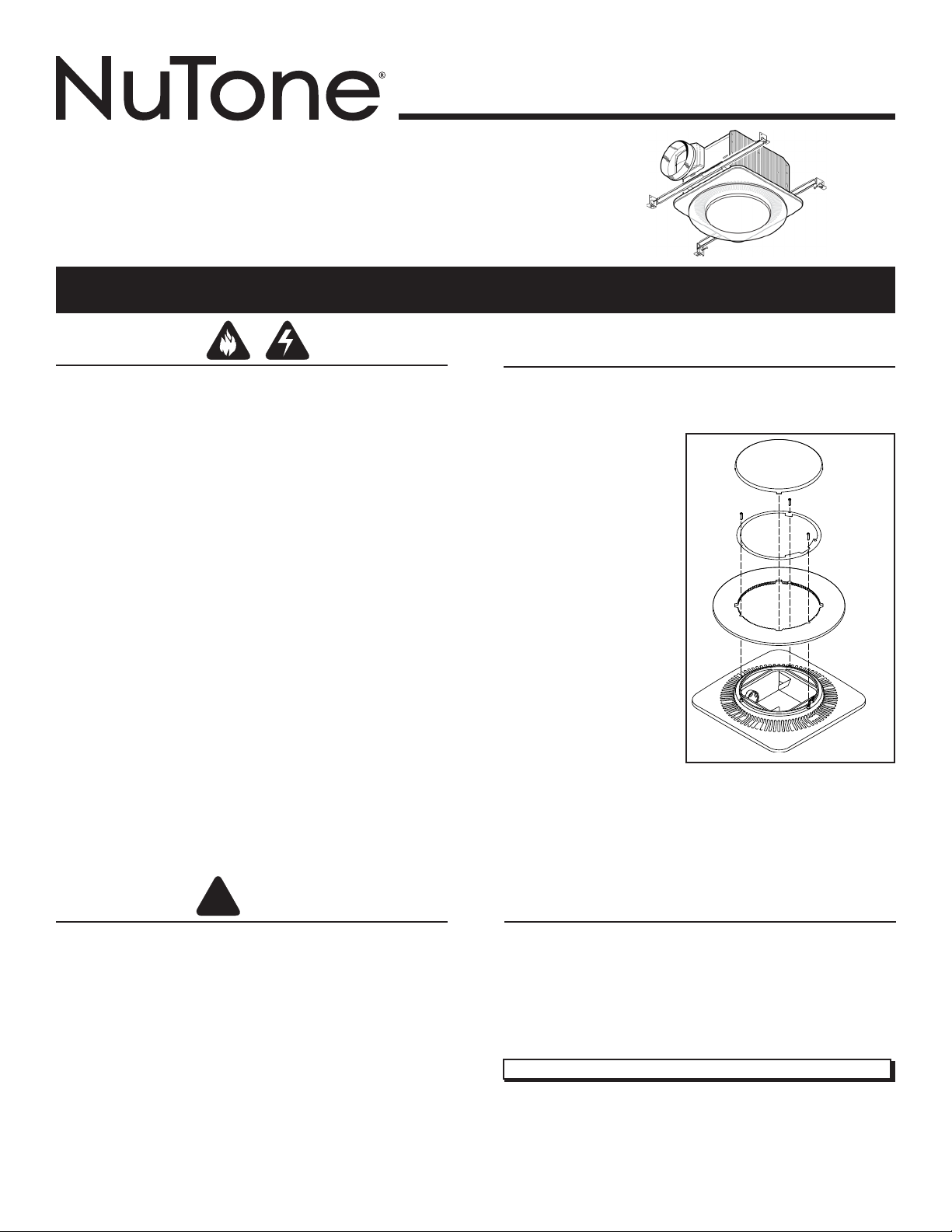
CLEANING & MAINTENANCE
For quiet and efficient operation, long life, and attractive
appearance - lower or remove grille and vacuum interior of unit
with the dusting brush attachment.
To clean the LED plate:
1. Remove grille from
ceiling and unplug
wiring from housing.
2. Remove lens.
3. Remove three (3)
screws from retention
ring.
4. Remove LED plate and
wash plate with a mild
detergent solution.
DO NOT USE
ABRASIVE
CLOTH, STEEL WOOL
PADS, SCOURING
POWDERS, CLEANING
SPRAYS OR
SOLVENTS.
5. Re-assemble grille
assembly and re-install
to fan housing.
The motor is permanently lubricated and never needs oiling. If the
motor bearings are making excessive or unusual noises, replace
the blower assembly (includes motor and impeller).
SCREWS
LENS
RETENTION
RING
LED
PLATE
GRILLE
CAUTION
1. For general ventilating use only. Do not use to exhaust
hazardous or explosive materials and vapors.
2. This product is designed for installation in ceilings up to a
12/12 pitch (45 degree angle). Duct connector must point up.
DO NOT MOUNT THIS PRODUCT IN A WALL.
3. To avoid motor bearing damage and noisy and/or unbalanced
impellers, keep drywall spray, construction dust, etc. off power
unit.
4. The LED light source is designed for this specific application
and can overheat if serviced by untrained personnel. If any
servicing is required, the product should be returned to an
authorized service facility for examination or repair.
5. Please read specification label on product for further
information and requirements.
OPERATION
The fan, light, and night light can be operated separately. Use a
3-function wall control. Do not use a dimmer switch to operate
the light. See “Connect Wiring” for details. Use of speed controls
other than the NuTone Models 78V and 78W may cause a motor
humming noise.
Register your product online at: www.nutone.com/register
Installer: Leave this manual with
the homeowner.
Page 2
MODEL QTNLEDA
Cooking
Equipment
Floor
COOKING AREA
Do not install above or
inside this area.
45
o
45
o
NOT FOR USE IN
A COOKING AREA.
Page 2
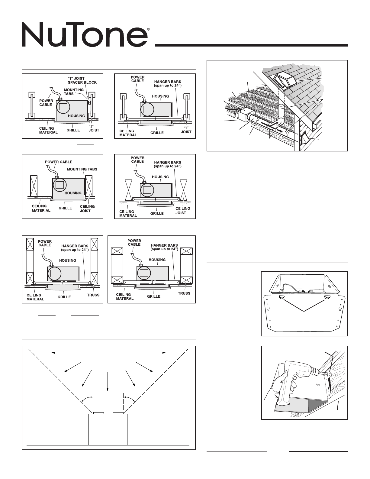
TYPICAL INSTALLATIONS
Housing mounted to I-joists.
Housing mounted to joists.
Housing mounted anywhere be-
tween I-joists using hanger bars.
Housing mounted anywhere between joists using hanger bars.
Seal duct
joints with
tape.
ROUND
ELBOWS*
ROOF CAP*
(with built-in
damper)
Keep duct
runs short.
OR
WALL CAP*
(with built-in
damper)
POWER
CABLE*
Seal gaps
around
Housing.
*Purchase
separately.
HOUSING
INSULATION*
(Place around and
over Fan Housing.)
FAN
ROUND
DUCT*
The ducting from this fan to the outside of the building has
a strong effect on the air flow, noise and energy use of the
fan. Use the shortest, straightest duct routing possible for
best performance, and avoid installing the fan with smaller
ducts than recommended. Insulation around the ducts can
reduce energy loss and inhibit mold growth. Fans installed
with existing ducts may not achieve their rated airflow.
6-inch round rigid metal duct is recommended for best
performance.
Use a roof cap or wall cap that has a built-in damper to
reduce backdrafts.
Plan to supply the unit with proper line voltage and
appropriate power cable.
Housing mounted anywhere be-
tween trusses using hanger bars.
Housing mounted anywhere between
trusses using hanger bars.
PLAN THE INSTALLATION
INSTALL HOUSING & DUCT
1a. Mount
housing
to joist or
I-joist.
Use a pliers to
bend housing
TABS out
to 900. Hold
housing in
place so that
the housing
tabs contact
the bottom
of the joist.
(use for mounting to I-Joist)
The housing
mounts with
four (4) screws
or nails. Screw
or nail housing
to joist through
lowest holes in
each mounting
flange, then
through
highest holes.
NOTE: Mounting to I-JOIST (shown) requires use of
SPACERS (included) between the highest hole of
each mounting flange and the I-joist.
TABS
SPACER
I-JOIST
OR
Page 3
1b. Mount housing anywhere between
trusses, joists, or I-joists using hanger
bars.
Sliding hanger bars are provided to allow for accurate
positioning of housing anywhere between framing. They can
be used on all types of framing (I-joist, standard joist, and
truss construction) and span up to 24”.
TAB
SCREWS (4)
MODEL QTNLEDA
Page 3
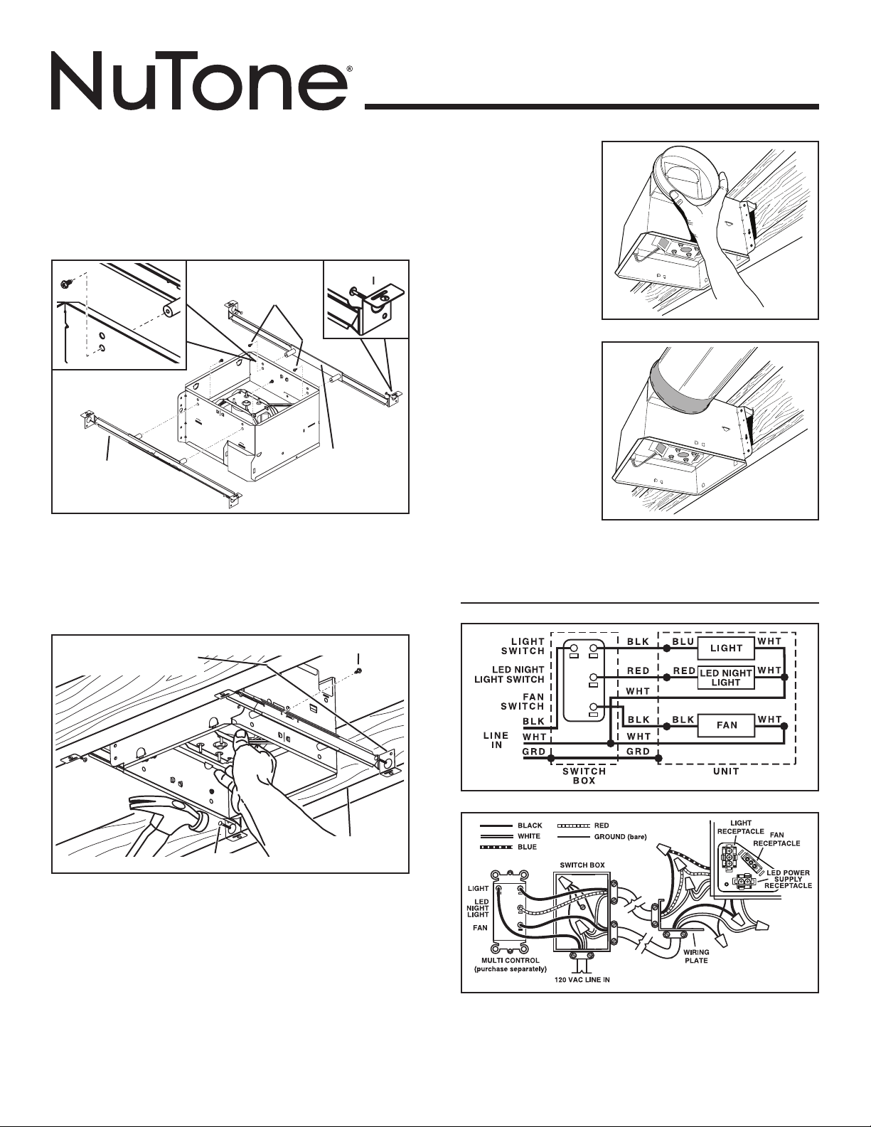
2. Attach
damper/duct
connector.
Snap damper /
duct connector
onto housing.
Make sure
connector is flush
with top of housing
and damper flap
falls closed.
STD
HANGER
BAR (4)
Attach the MOUNTING CHANNELS to the housing using
the SCREWS supplied. Make sure TABS face “up” as shown.
Use the set of channel mounting holes (marked “STD”) to
mount the housing flush with the bottom of the drywall. Use
the other set of holes (not marked) to mount the housing
flush with the top of the drywall.
HOLE FOR OPTIONAL
SCREW MOUNTING (4)
MOUNTING
CHANNEL (2)
SCREW (2)
*
3. Install
6-inch or
4-inch round
ductwork.
Connect 6-inch
or 4-inch round
ductwork to
damper/ duct
connector or
reducer. Run
ductwork to a roof
cap or wall cap.
Tape all ductwork
connections to make them secure and air tight.
CONNECT WIRING
BOTTOM EDGE
NAIL (4)
Extend HANGER BARS to the width of the framing.
Hold ventilator in place with the hanger bar tabs wrapping
around the BOTTOM EDGE OF THE FRAMING.
NAIL ventilator to framing or fasten with screws (not provided)
through HOLES near nails.
* To ensure a noise-free mount: Secure hanger bars together
with SCREWS or use a pliers to crimp mounting channels
tightly around hanger bars.
OF FRAMING
4. Connect electrical wiring.
Run 120 VAC house wiring to installation location. Use
proper UL approved connector to secure house wiring to
wiring plate. Connect wires as shown in wiring diagrams.
Page 4
MODEL QTNLEDA
Page 4
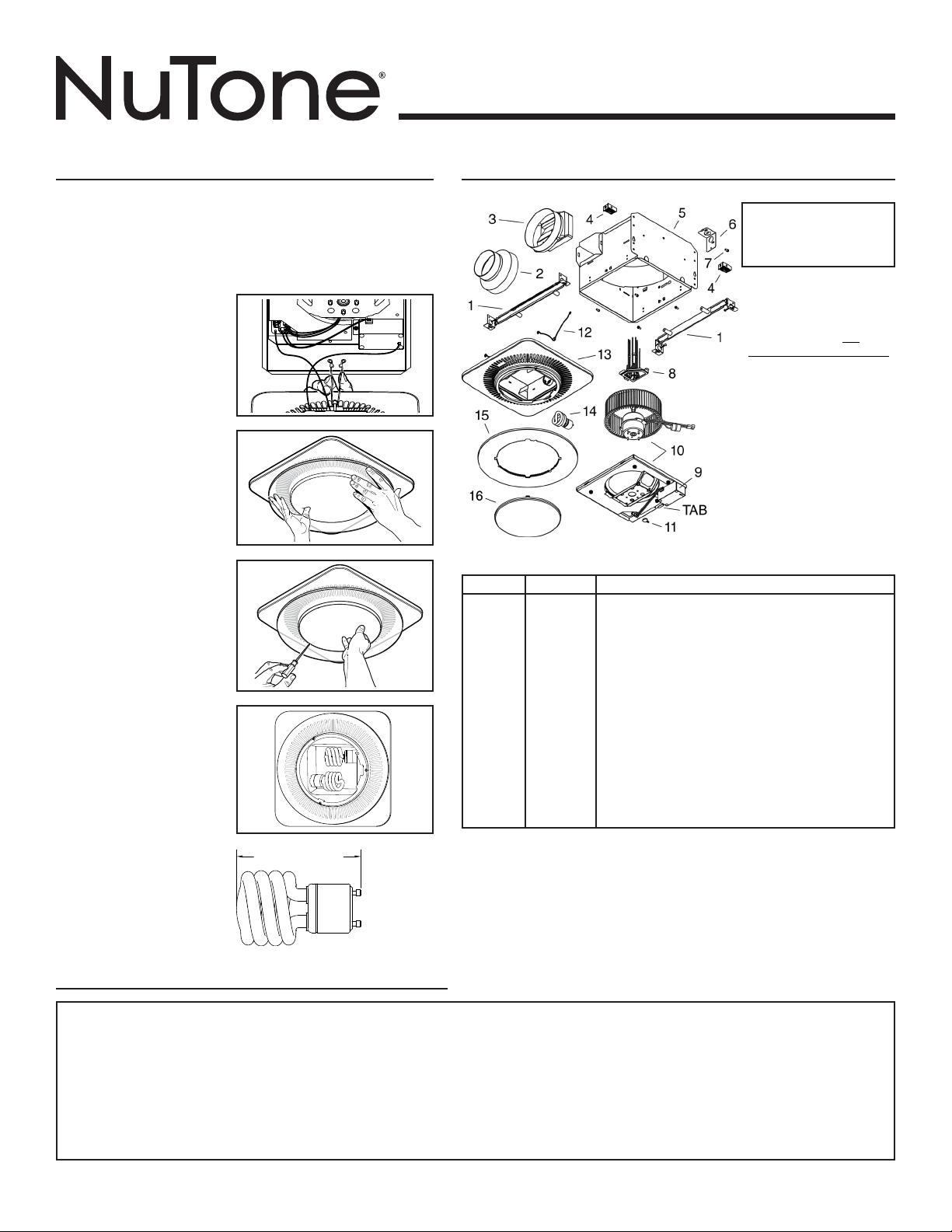
INSTALL GRILLE
5. Finish ceiling.
Install ceiling material. Cut out around housing.
6. Plug in wiring.
Plug wiring into proper receptacles.
7. Attach grille to
housing.
Squeeze grille springs
and insert them into
tabs on each side of
housing.
8. Push grille
against ceiling.
9. Remove light
lens.
Carefully insert a
small flat-blade
screwdriver between
grille and lens. Pry
lens out.
10. Install light
bulbs.
Purchase (2) 18W
(max.), type GU24
fluorescent lamps with
M.O.L. (maximum
overall length) of 3.9”
(100mm) as illustrated
below.
Insert lamps and bulb
into their sockets.
Replace lens.
3.9" (100mm) M.O.L.
SERVICE PARTS
Replacement parts can be
ordered on our website.
Please visit us at
www.nutone.com
SERVICE NOTE To
remove Blower Assembly:
Unplug motor. Remove
thumbscrew (12) from
motor plate flange. Find
the single TAB on the
motor plate (located next
to the receptacle). Push
up near motor plate tab
while pushing out on side
of housing. Or insert a
straight-blade screwdriver
into slot in housing (next to
tab) and twist screwdriver.
KEY NO. PART NO. DESCRIPTION
1 SQTHB1 HANGER BAR KIT
2 475 DUCT REDUCER 6” TO 4”
3 97018562 DUCT CONNECTOR - 6”
4 99111293 SPACER (2 REQ’D)
5 97016466 HOUSING
6 98010102 WIRING PLATE
7 99170245 SCREW, #8-18 X .375
8 97018552 WIRE PANEL/HARNESS ASSEMBLY
9 97020045 CONTROL ASSEMBLY
10 97020046 SERVICE ASSEMBLY, BLOWER
(INCLUDES KEY NO. 11)
11 99420665 THUMBSCREW, #8-18 X .375
12 99140199 GRILLE SPRING (2 REQ’D)
13 97018480 GRILLE ASSEMBLY
14 99271381 BULB, GU24, 18W FLUORESCENT (2 REQ’D)
15 99111530 RING
16 99111529 LENS
* Not shown assembled.
Order service parts by “Part No.” - not by “Key No.”
WARRANTY
Broan-NuTone warrants to the original consumer purchaser of its products that such products will be free from defects in materials or workmanship for a period of three years from the date of original purchase. THERE ARE NO OTHER
WARRANTIES, EXPRESS OR IMPLIED, INCLUDING, BUT NOT LIMITED TO, IMPLIED WARRANTIES OF MERCHANTABILITY OR FITNESS FOR A PARTICULAR PURPOSE.
During this three-year period, Broan-NuTone will, at its option, repair or replace, without charge, any product or part which is found to be defective under normal use and service.
THIS WARRANTY DOES NOT EXTEND TO FLUORESCENT L AMP STARTERS, TUBES, HALOGEN AND INCANDESCENT BULBS, FUSES, FILTERS, DUCTS, ROOF CAPS, WALL CAPS AND OTHER ACCESSORIES FOR DUCTING.
This warranty does not cover (a) normal maintenance and service or (b) any products or parts which have been subject to misuse, negligence, accident, improper maintenance or repair (other than by Broan-NuTone), faulty installation
or installation contrary to recommended installation instructions.
The duration of an implied warranty is limited to the three-year period as specified for the express warranty. Some states do not allow limitation on how long an implied warranty lasts, so the above limitation may not apply to you.
BROAN-NUTONE’S OBLIGATION TO REPAIR OR REPLACE, AT BROAN-NUTONE’S OPTION, SHALL BE THE PURCHASER’S SOLE AND EXCLUSIVE REMEDY UNDER THIS WARRANTY. BROAN-NUTONE SHALL NOT BE LIABLE FOR
INCIDENTAL, CONSEQUENTIAL OR SPECIAL DAMAGES ARISING OUT OF OR IN CONNECTION WITH PRODUCT USE OR PERFORMANCE. Some states do not allow the exclusion or limitation of incidental or consequential damages, so the
above limitation may not apply to you.
This warranty gives you specific legal rights, and you may also have other rights, which vary from state to state. This warranty supersedes all prior warranties.
To qualify for warranty service, you must (a) notify Broan-NuTone at the address or telephone number stated below, (b) give the model number and part identification and (c) describe the nature of any defect in the product or part. At the
time of requesting warranty service, you must present evidence of the original purchase date.
Broan-NuTone LLC, 926 W. State Street, Hartford, Wisconsin 53027 www.nutone.com 888-336-3948
BROAN-NUTONE THREE YEAR LIMITED WARRANTY
99045484A
Page 5

MODÈLE QTNLEDA
!
VENTILATEUR /
LUMIÈRE / VEILLEUSE
DEL MODÈLE QTNLEDA
LIRE CES DIRECTIVES ET LES CONSERVER
Page 5
AVERTISSEMENT
AFIN DE DIMINUER LES RISQUES D’INCENDIE,
D’ÉLECTROCUTION OU DE BLESSURES, SUIVEZ CES
DIRECTIVES :
1. N’utilisez cet appareil que de la manière prévue par le fabricant.
Si vous avez des questions, communiquez avec le fabricant à
l’adresse ou au numéro de téléphone indiqués dans la garantie.
2. Avant de procéder à l’entretien ou au nettoyage de l’appareil, coupez
l’alimentation du panneau électrique et verrouillez l’interrupteur
principal afin d’empêcher que le courant ne soit accidentellement
rétabli. S’il est impossible de verrouiller l’interrupteur principal,
fixez solidement un message d’avertissement, par exemple une
étiquette, sur le panneau électrique.
3. La pose de l’appareil et les travaux d’électricité doivent être
effectués par des personnes qualifiées conformément à la
réglementation en vigueur, notamment les normes de la
construction ayant trait à la protection contre les incendies.
4. Pour éviter les refoulements, l’apport d’air doit être suffisant pour
brûler les gaz produits par les appareils à combustion et les
évacuer dans le conduit de fumée (cheminée). Respectez les
directives du fabricant de l’appareil de chauffage et les normes de
sécurité, notamment celles publiées par la National Fire Protection
Association (NFPA), l’American Society for Heating, Refrigeration
and Air Conditioning Engineers (ASHRAE) et les codes des
autorités locales.
5. Veillez à ne pas endommager le câblage électrique ou d’autres
équipements non apparents lors de la découpe ou du perçage du
mur ou du plafond.
6. Les ventilateurs canalisés doivent toujours rejeter l’air à l’extérieur.
7. Cet appareil peut être installé au-dessus d’une enceinte de
baignoire ou de douche s’il est branché sur un circuit de dérivation
protégé par un disjoncteur de fuite à la terre.
8. Cet appareil doit être relié à une mise à la terre.
NETTOYAGE ET ENTRETIEN
Pour un fonctionnement silencieux et efficace, ainsi qu’une durabilité
et une apparence supérieures, abaissez ou enlevez la grille et
nettoyez l’intérieur de l’appareil avec un aspirateur muni d’une brosse
à épousseter.
Pour nettoyer la plaque
DEL :
1.
Enlevez la grille du plafond
et débranchez le fil
du boîtier.
2. Retirez la lentille
d’éclairage.
3. Enlevez les trois (3) vis
de l’anneau de retenue.
4. Enlevez la plaque DEL et
lavez-la avec une solution
de détergent doux.
N’UTILISEZ PAS DE
CHIFFONS ABRASIFS,
DE LAINE D’ACIER, DE
POUDRE À RÉCURER
NI DE NETTOYANTS EN
PULVÉRISATEUR OU
DE SOLVANTS.
5. Remontez l’ensemble de
grille et réinstallez le tout dans le boîtier du ventilateur.
Le moteur est lubrifié en permanence et n’a pas besoin d’être huilé.
Si les roulements du moteur sont anormalement bruyants, remplacez
l’ensemble de ventilateur (incluant le moteur et la roue à ailettes).
VIS
LENTILLE
ANNEAU DE
RETENUE
PLAQUE
DEL
GRILLE
ATTENTION
1. Pour ventilation générale uniquement. Ne pas utiliser cet appareil
pour évacuer des matières ou des vapeurs dangereuses ou
explosives.
2. Ce produit peut être installé dans un plafond dont la pente n’excède
pas 12/12 (45 degrés). Le raccord de conduit doit pointer vers le
haut. CE PRODUIT NE PEUT PAS ÊTRE POSÉ DANS UN MUR.
3. Pour éviter d’endommager les roulements de moteur, de
déséquilibrer les pales ou de les rendre bruyantes, débarrassez
l’appareil de la poussière de plâtre, de construction, etc.
4. La source lumineuse à DEL est conçu pour cette application
spécifique et peuvent surchauffer si desservis par du personnel
non formé. Si aucun entretien n’est nécessaire, le produit doit
être retourné à un centre de service autorisé pour examen ou
réparation.
5. Veuillez lire l’étiquette de spécifications du produit pour obtenir
plus de renseignements, notamment sur les exigences.
FONCTIONNEMENT
Le ventilateur, l’éclairage et la veilleuse peuvent être commandés
séparément. Utilisez une commande murale à trois fonctions. N’utilisez
pas un gradateur pour commander la lumière. Pour plus de détails,
consultez la section « Câblage ». L’utilisation de commandes de vitesse
autres que les modèles NuTone 78V et 78W risque de causer un
grondement du moteur.
Enregistrez votre produit en ligne à : www.nutone.com/register
Installateur : Veuillez remettre ce
manuel au propriétaire.
Page 6

MODÈLE QTNLEDA
BLOC DE CALE DE
SOLIVE EN « I »
ERGOTS DE
MONTAGE
FIL
D’ALIMENTATION
BOÎTIER
MATÉRIAU DU
PLAFOND
GRILLE
SOLIVE
EN « I »
FIL
D’ALIMENTATION
BOÎTIER
FERME
GRILLE
MATÉRIAU DU
PLAFOND
BARRES DE
SUSPENSION
(s’allongent jusqu’à
61 cm [24 po])
FIL
FIL
FIL
D’ALIMENTATION
BARRES DE
SUSPENSION
(s’allongent jusqu’à
61 cm [24 po])
BOÎTIER
FERME
GRILLE
MATÉRIAU DU
PLAFOND
Appareil
de cuisson
Plancher
ZONE DE CUISSON
Ne pas installer
au-dessus ou à l’intérieur
de cette zone.
45
o
45
o
NE PAS INSTALLER
DANS UNE ZONE
DE CUISSON.
Page 6
INSTALLATION TYPE
MATÉRIAU DU
PLAFOND
Boîtier xé à des solives en « i ».
FIL D’ALIMENTATION
ERGOTS DE MONTAGE
BOÎTIER
MATÉRIAU
DU PLAFOND
GRILLE
SOLIVE DU
PLAFOND
Boîtier xé aux solives
Boîtier monté n’importe où entre des solives
en « I » à l’aide des barres de suspension.
MATÉRIAU
DU PLAFOND
Boîtier monté n’importe où entre des
solives à l’aide des barres de suspension.
D’ALIMENTATION
GRILLE
D’ALIMENTATION
BARRES DE SUSPENSION
(s’allongent jusqu’à
61 cm [24 po])
BOÎTIER
SOLIVE
GRILLE
BARRES DE SUSPENSION
(s’allongent jusqu’à
61 cm [24 po])
BOÎTIER
GRILLE
EN « I »
SOLIVE DU
PLAFOND
(Répartir autour
et au-dessus du boîtier
du ventilateur.)
BOÎTIER DE
VENTILATEUR
CORDON
D’ALIMENTATION*
Calfeutrer
les espaces
autour du
ventilateur.
CONDUIT
ISOLATION*
ROND*
Sceller les joints
de conduit avec
du ruban adhésif.
* Vendu séparément.
COUDES
RONDS*
CAPUCHON
DE TOIT*
(avec clapet
intégré)
Garder le
tracé des
conduits court.
OU
CAPUCHON
MURAL*
(avec clapet intégré)
Les conduits allant de ce ventilateur jusqu’à l’extérieur de
l’habitation ont une grande influence sur le débit d’air, le bruit
du ventilateur et sa consommation d’énergie. Pour obtenir le
meilleur rendement, utilisez les conduits les plus courts et
les plus droits que possible et évitez d’utiliser des conduits
plus petits que ceux recommandés. L’isolation des conduits
peut contribuer à réduire les pertes d’énergie et éviter la
prolifération de moisissures. Les ventilateurs installés sur
d’anciens conduits pourraient ne pas produire leur débit d’air
nominal.
Pour un rendement optimal, il est recommandé d’utiliser des
conduits métalliques ronds de 15,2 cm (6 po) de diamètre.
Utilisez un capuchon de toit ou un capuchon mural muni d’un
clapet intégré afin de réduire les refoulements d’air.
Prévoyez l’alimentation de l’appareil avec la tension adéquate
et le câble approprié.
Boîtier monté n’importe où entre des
fermes de toit à l’aide des
PLANIFICATION DE L’INSTALLATION
barres de suspension.
Boîtier monté n’importe où entre des fermes
de toit à l’aide des barres de suspension.
INSTALLATION DU BOÎTIER
ET DES CONDUITS
1a. Fixez le boîtier
aux solives ou
solives en I.
Utilisez des pinces
pour plier les
ERGOTS vers
l’extérieur jusqu’à
90°. Maintenez le
boîtier en place de
sorte que les ergots
touchent au bas de
se fixe avec quatre
la solive. Le boîtier
CALE (pour fixation aux
(4) vis ou clous.
Vissez ou clouez-le
à la solive au travers
des trous les plus
bas de chaque bride
de montage, puis au
travers des trous les
plushauts.
REMARQUE : La
fixation aux SOLIVES
EN I (illustré) exige l’utilisation de CALES (incluses)
entre le trou le plus haut de chaque bride de montage et
la solive en I.
OU
ERGOTS
solives en I)
SOLIVES EN I
Page 7

ENTRÉE
APPAREIL
BOÎTE
D’INTERRUPTEUR
INTERRUPTEUR
D’ÉCLAIRAGE
INTERRUPTEUR
DE VEILLEUSE DEL
INTERRUPTEUR
DU VENTILATEUR
BLANC
FIL DE TERRE
NOIR
NOIR
NOIR NOIR
BLANC
BLANC
FIL DE TERRE
ROUGE
ROUGE
BLEU
ÉCLAIRAGE
VEILLEUSE
DEL
VENTILATEUR
BLANC
BLANC
BLANC
ÉCLAIRAGE
VEILLEUSE
DEL
COMMANDE
MULTIFONCTIONS
(vendue séparément)
PLAQUE
DE CÂBLAGE
PRISE DU
VENTILATEUR
PRISE DE LA
VEILLEUSE DEL
SOCLE
D’AMPOULE
ALIMENTATION 120 VCA
NOIR
BLANC
BLEU
ROUGE
FIL DE TERRE (nu)
BOÎTE D’INTERRUPTEUR
VENTILATEUR
1b. Fixez le boîtier n’importe où entre les
fermes, solives ou solives en « I » avec les
barres de suspension.
Les barres de suspension fournies permettent de positionner
avec précision le boîtier entre la charpente. Elles s’utilisent pour
tous les types de charpente (solives en I, solives ordinaires et
fermes de toit) et s’allongent jusqu’à 61 cm (24 po).
ERGOT
VIS (4)
STD
BARRE DE
SUSPENSION (4)
Fixez les PROFILÉS DE MONTAGE au boîtier à l’aide des
VIS fournies. Assurez-vous que les ERGOTS soient vers le
haut, tel qu’illustré. Utilisez les trous de montage des profilés
(marqués « STD ») pour fixer le boîtier au même niveau que
le dessous gypse. Utilisez les autres trous (non marqués)
pour fixer le boîtier au même niveau que le dessus du gypse.
PROFILÉS DE
MONTAGE (2)
MODÈLE QTNLEDA
Page 7
2. Fixez le clapet/
raccord de
conduit.
Enclenchez le
clapet / raccord
de conduit sur le
boîtier. Assurezvous que le haut
du raccord est à
égalité avec le
boîtier et que le
clapet retombe
fermé.
3. Installez un
conduit rond
de 15,2 cm ou
10,2 cm (6po
ou 4 po).
Raccordez le
conduit rond
de 15,2 cm ou
10,2 cm (6 po
ou 4 po) au
clapet / raccord
de conduit ou
au réducteur.
Acheminez le conduit jusqu’au capuchon mural ou de toit.
Étanchez tous les joints avec du ruban adhésif.
CÂBLAGE
TROU POUR VISSAGE
Allonger les BARRES DE SUSPENSION à la même largeur
Maintenez le ventilateur en place avec les ergots des barres
CLOUEZ le ventilateur à la charpente ou fixez-le avec des vis
* Pour assurer un montage silencieux : Fixez les barres
VIS (2)
FACULTATIF (4)
*
BORD INFÉRIEUR
CLOU (4)
DE LA CHARPENTE
que la charpente.
de suspension épousant le BORD INFÉRIEUR DE LA
CHARPENTE.
(non fournies) au travers des TROUS à côté des clous.
de suspension ensemble avec des VIS ou, à l’aide de
pinces, écrasez fermement les profilés autour des barres de
suspension.
4. Branchement du câblage électrique
Acheminez un fil de 120 VCA jusqu’au lieu d’installation.
Fixez le fil à la plaque de câblage avec le connecteur
approprié homologué UL. Connectez les fils, tel qu’illustré
dans les schémas de câblage.
Page 8

MODÈLE QTNLEDA
Page 8
INSTALLATION DE LA GRILLE
5. Finissez la surface du plafond.
Installez le matériau du plafond. Coupez-le autour du boîtier.
6. Branchez le câblage.
Branchez le câblage dans des récipients appropriés.
7. Fixez la grille au
boîtier.
Pincez les ressorts de
la grille set insérez-les
dans les encoches
de chaque côté du
boîtier.
8. Poussez la grille
contre le plafond.
9. Retirez
la lentille
d’éclairage.
Insérez délicatement
un petit tournevis à
lame plate entre la
grille et la lentille.
Dégagez la lentille.
10. Installez les
ampoules.
Achetez (2) ampoules
fluorescentes de type
GU24 d’au maximum
18 watts, d’une
longueur maximale
totale de 100 mm
(3,9po), tel qu’illustré
ci-dessous.
Insérez les ampoules
dans leurs socles.
Replacez la lentille.
Longueur maximale
de 100 mm (3,9 po)
PIÈCES DE RECHANGE
Les pièces de rechange
peuvent être commandées
sur notre site Web.
Visitez notre site à www.
nutone.com
NOTE RELATIVE AU
SERVICE Pour enlever
l’ensemble de ventilateur :
Débranchez le moteur.
Enlevez la vis à oreilles
(12) du rebord de la
plaque du moteur.
Trouvezl’ERGOT sur
la plaque du moteur
(àproximité de la prise).
Soulevez l’ergot tout en
poussant sur les côtés du
boîtier. Ouencore, insérez
la lame d’un tournevis plat
dans la fente du boîtier
(àcôté de l’ergot) et
tournez le tournevis.
REPÈRE N° DE PIÈCE DESCRIPTION
1 SQTHB1
2 475
3 97018562
4 99111293
5 97016466
6 98010102
7 99170245
8 97018552
91097020045
97020046
11 99420665
12 99140199
13 97018480
14 99271381
15 99111530
16 99111529
* Illustré démonté.
Veuillez commander les pièces par « N° de pièce » et non par « N° de repère ».
ENSEMBLE DE BARRES DE SUSPENSION
RÉDUCTEUR DE CONDUIT DE 15,2 À 10,2 CM (6 À 4 PO)
RACCORD DE CONDUIT - 15,2 CM (6 PO)
CALES (2 REQUISES)
BOÎTIER
PLAQUE DE CÂBLAGE
VIS, n° 8-18 x 0,375
PANNEAU DE CÂBLAGE / FAISCEAU DE FILS
ENSEMBLE DE COMMANDE
ENSEMBLE DE RÉPARATION, VENTILATEUR
(COMPREND REPÈRES No 11)
VIS À OREILLES, n° 8-18 x 0,375
RESSORT DE GRILLE (2 REQUIS)
ENSEMBLE DE GRILLE
AMPOULE, GU24, 18W, FLUORESCENTE (2 REQUISES)
ANNEAU
LENTILLE
GARANTIE
Broan-NuTone garantit à l’acheteur original que les produits vendus en vertu de la présente sont libres de tout vice de matériau ou de fabrication pour une période de trois ans à compter de la date d’achat originale. CETTE GARANTIE NE COMPORTE
AUCUNE AUTRE GARANTIE, EXPRESSE OU TACITE, Y COMPRIS, MAIS SANS S’Y LIMITER, LES GARANTIES TACITES DE VALEUR MARCHANDE OU D’ADAPTATION À UN USAGE PARTICULIER.
Durant cette période de trois ans, Broan-NuTone réparera ou remplacera gratuitement, à sa discrétion, tout produit ou toute pièce jugés défectueux dans des conditions normales d’utilisation.
CETTE GARANTIE NE S’APPLIQUE PAS AUX TUBES FLUORESCENTS ET AUX DÉMARREURS, NI AUX AMPOULES HALOGÈNES OU INCANDESCENTES, FUSIBLES, FILTRES, CONDUITS, CAPUCHONS DE TOIT, CAPUCHONS MURAUX ET AUTRES
ACCESSOIRES POUR CONDUITS.
Cette garantie ne couvre pas (a) les frais d’entretien ou de service normaux ni (b) tout produit ou toute pièce soumis à un abus, une négligence, un accident, un entretien ou une réparation inadéquats (autres que ceux effectués par Broan-NuTone),
une mauvaise installation ou une installation contraire aux instructions recommandées.
La durée de toute garantie tacite est limitée à cette période de trois ans, tel que stipulé pour la garantie expresse. Certains territoires ou provinces interdisant de limiter la durée d’une garantie tacite, la limitation ci-dessus peut ne pas s’appliquer à votre situation.
L’OBLIGATION POUR BROAN-NUTONE DE RÉPARER OU DE REMPLACER LE PRODUIT, À SA DISCRÉTION, CONSTITUE LE SEUL RECOURS DE L’ACHETEUR EN VERTU DE LA PRÉSENTE GARANTIE. BROAN-NUTONE NE PEUT ÊTRE TENUE
RESPONSABLE DES DOMMAGES INDIRECTS OU CONSÉCUTIFS NI DES DOMMAGES-INTÉRÊTS PARTICULIERS DÉCOULANT DE L’UTILISATION OU DU RENDEMENT DU PRODUIT. Certains territoires ou provinces interdisent l’exclusion ou la
restriction des dommages indirects ou consécutifs. La restriction susmentionnée peut donc ne pas s’appliquer dans votre cas.
La présente garantie vous confère des droits spécifiques reconnus par la loi. D’autres droits pourraient également vous être accordés selon la législation locale en vigueur. La présente garantie remplace toutes les autres garanties précédentes.
Pour vous prévaloir de cette garantie, vous devez (a) aviser Broan-NuTone à l’adresse ou au numéro de téléphone indiqués ci-dessous, (b) donner le numéro de modèle du produit et le numéro d’identification de la pièce et (c) décrire la nature de la
défectuosité du produit ou de la pièce. Lors de votre demande de garantie, vous devez présenter une preuve de la date d’achat originale.
Broan-NuTone LLC, 926 W. State Street, Hartford, Wisconsin 53027 www.nutone.com 888-336-3948
GARANTIE LIMITÉE DE TROIS ANS DE BROAN-NUTONE
99045484A
Page 9

MODELO QTNLEDA
!
MODELO QTNLEDA VENTILADOR/
LUZ/LUZ NOCTURNA DE LED
LEA Y CONSERVE ESTAS INSTRUCCIONES
Página 9
ADVERTENCIA
PARA REDUCIR EL RIESGO DE INCENDIO, DESCARGA ELÉCTRICA O
LESIONES CORPORALES, OBSERVE LO SIGUIENTE:
1. Use la unidad sólo de la manera indicada por el fabricante. Si tiene
preguntas, comuníquese con el fabricante a la dirección o al número
telefónico que se incluye en la garantía.
2. Antes de dar servicio a la unidad o de limpiarla, interrumpa el suministro
eléctrico en el panel de servicio y bloquee los medios de desconexión
del servicio para evitar que la electricidad se reanude accidentalmente.
Cuando no sea posible bloquear los medios de desconexión del servicio,
fije firmemente una señal de advertencia (como una etiqueta) en un lugar
visible del panel de servicio.
3. Una o más personas calificadas deben realizar el trabajo de instalación
y el cableado eléctrico, de acuerdo con todos los códigos y normas
correspondientes, incluidos los códigos y normas de construcción
específicos de protección contra incendios.
4. Se necesita suficiente aire para que se lleve a cabo una combustión
y una extracción adecuadas de los gases a través del tubo de humos
(chimenea) del equipo quemador de combustible, con el fin de evitar el
contratiro. Siga las directrices y las normas de seguridad del fabricante del
equipo de calefacción, como las publicadas por la Asociación Nacional de
Protección contra Incendios (National Fire Protection Association, NFPA),
la Sociedad Americana de Ingenieros de Calefacción, Refrigeración y
Aire Acondicionado (American Society for Heating, Refrigeration and Air
Conditioning Engineers, ASHRAE) y las autoridades normativas locales.
5. Al cortar o perforar a través de la pared o del cielo raso, tenga cuidado
de no dañar el cableado eléctrico ni otros servicios ocultos.
6. Los ventiladores en conductos siempre deben ventearse hacia el exterior.
7. Esta unidad puede instalarse sobre una tina o ducha siempre que se
conecte a un GFCI (interruptor accionado por pérdida de conexión a
tierra) en un circuito de derivación protegido.
8. Esta unidad debe estar conectada a tierra.
LIMPIEZA Y MANTENIMIENTO
Para lograr un funcionamiento silencioso y eficiente como también
larga vida y apariencia atractiva del producto, baje o retire la rejilla
y aspire el interior de la unidad con el accesorio del cepillo para
sacudir polvo.
Para limpiar la placa
deLED:
1. Retire la rejilla del cielo
raso y desconecte el
cableado de la cubierta.
2. Retire la lente.
3. Retire tres (3) tornillos
del anillo de retención.
4. Retire la placa de LED y
lávela con una solución
de detergente suave.
NO USE PAÑOS
ABRASIVOS,
ALMOHADILLAS DE
LANA DE ACERO,
POLVOS ABRASIVOS
NI SPRAYS O
SOLVENTES DE
LIMPIEZA.
5. Arme nuevamente el conjunto de la rejilla y reinstálela en la
cubierta del ventilador.
El motor está permanentemente lubricado y nunca necesitará
ponerle aceite. Si los cojinetes del motor están haciendo ruido
excesivo o inusitado, reemplace el conjunto del ventilador (incluye
el motor y el impulsor).
TORNILLOS
LENTE
ANILLO DE
RETENCIÓN
PLACA
DE LED
REJILLA
PRECAUCIÓN
1. Sólo para usarse como medio de ventilación general. No debe usarse
para la extracción de materiales o vapores peligrosos o explosivos.
2. Este producto está diseñado para instalarse en cielos rasos con una
pendiente de hasta 12/12 (en un ángulo de 45 grados). El conector de
conductos debe apuntar hacia arriba. NO MONTE ESTE PRODUCTO
EN LA PARED.
3. Para evitar daños a los cojinetes del motor y rotores ruidosos o
desbalanceados, mantenga la unidad de potencia protegida contra
rociados de yeso, polvos de construcción, etc.
4. La fuente de luz LED está diseñado para esta aplicación específica y
provoca el calentamiento atendidos por personal no capacitado. Si se
requiere ningún tipo de servicio, el producto debe ser devuelto a un centro
de servicio autorizado para su revisión o reparación.
5. Lea la etiqueta de especificaciones que tiene el producto para ver
información y requisitos adicionales.
FUNCIONAMIENTO
El ventilador, la luz y la luz nocturna pueden funcionar separadamente.
Utilice un control de pared de 3 funciones. No utilice un reductor de
intensidad para hacer funcionar la luz (consulte los detalles en la
sección “Conexión eléctrica”). Los controles de velocidad diferentes
a los modelos 78V y 78W de NuTone podrían ocasionar un zumbido
en el motor.
Registre su producto en el sitio web www.nutone.com/register
Aviso al instalador: Deje este
manual con el dueño de la casa.
Page 10

MODELO QTNLEDA
VIGUETA
“I”
REJILLA
CABLE
ELÉCTRICO
BARRAS DE SUSPENSIÓN
(se extienden hasta
24 pulg. [61 cm])
CUBIERTA
MATERIAL
DEL CIELO
RASO
CABLE ELÉCTRICO
LENGÜETAS DE MONTAJE
CUBIERTA
MATERIAL DEL
CIELO RASO
REJILLA
VIGUETA DE
CIELO RASO
CABLE
ELÉCTRICO
CUBIERTA
ARMADURA
REJILLA
MATERIAL DEL
CIELO RASO
BARRAS DE
SUSPENSIÓN
(se extienden hasta
24 pulg. [61 cm])
VIGUETA
“I”
REJILLA
CABLE
ELÉCTRICO
BARRAS DE SUSPENSIÓN
(se extienden hasta
24 pulg. [61 cm])
CUBIERTA
MATERIAL
DEL CIELO
RASO
BARRAS DE SUSPENSIÓN
(se extienden hasta
24 pulg. [61 cm])
CABLE
ELÉCTRICO
MATERIAL DEL
CIELO RASO
REJILLA
VIGUETA DE
CIELO RASO
CUBIERTA
CABLE
ELÉCTRICO
BARRAS DE
SUSPENSIÓN
(se extienden hasta
24 pulg. [61 cm])
CUBIERTA
ARMADURA
REJILLA
MATERIAL DEL
CIELO RASO
Equipo
de cocina
Piso
ÁREA DE COCINA
No instalar el producto sobre
esta área ni dentro de ella.
45
o
45
o
NO USAR EL
PRODUCTO EN UN
ÁREA DE COCINA.
Página 10
INSTALACIONES TÍPICAS
Montaje de la cubierta en viguetas “I”.
Montaje de la cubierta en viguetas.
Montaje de la cubierta en cualquier parte
entre las viguetas “I” por medio de
barras de suspensión.
Montaje de la cubierta en cualquier parte
entre las viguetas por medio de
barras de suspensión.
CAPUCHÓN
PARA TEJADO*
(con regulador
de tiro
incorporado)
Asegurarse
de que los
conductos
sean cortos.
CAPUCHÓN
DE PARED*
(con regulador
de tiro incorporado)
del conducto
con cinta.
AISLACIÓN*
(Colocar alrededor y sobre
el compartimiento para el ventilador).
VENTILADOR
COMPARTIMIENTO
CABLE DE
ALIMENTACIÓN*
Sellar las
cavidades
alrededor del
compartimiento.
CONDUCTO
CIRCULAR*
Sellar las uniones
*Comprar por separado.
OR
O
CODOS
CIRCULARES*
Los conductos desde este ventilador hacia el exterior del
edificio tienen un gran efecto sobre el flujo de aire, el ruido y
el uso de energía del ventilador. Utilice el tramo de conductos
más corto y recto posible para obtener un desempeño óptimo
y evite instalar el ventilador con conductos menores que los
recomendados. El aislamiento alrededor de los conductos
puede reducir la pérdida de energía e inhibir el desarrollo de
moho. Los ventiladores instalados en conductos existentes
podrían no obtener el flujo de aire nominal.
Para un mejor desempeño, se recomienda utilizar conductos
metálicos redondos y rígidos de 6 pulg. (15,2 cm).
Instale una tapa de techo o de pared que tenga un regulador
de tiro integrado, con el fin de reducir los contratiros.
Haga los preparativos para alimentar la unidad con el voltaje
de línea y el cable eléctrico apropiados.
Montaje de la cubierta en cualquier parte
PLANEACIÓN DE LA INSTALACIÓN
entre armaduras por medio de
barras de suspensión.
Montaje de la cubierta en cualquier parte entre
armaduras por medio de barras de suspensión.
INSTALE LA CUBIERTA Y
EL CONDUCTO
1a. Instale la
cubierta en
las viguetas o
viguetas “I”.
Con alicates, doble
las LENGÜETAS
de la cubierta
a un ángulo de
90º. Sostenga la
cubierta en su lugar
de manera que
las lengüetas de
la cubierta hagan
contacto con la parte
inferior de la vigueta.
Para el montaje de
la cubierta se utilizan
cuatro (4) tornillos
o clavos. Atornille o
clave la cubierta a
la vigueta a través
de los orificios
más bajos de cada
brida de montaje, y
seguidamente a través de los más altos.
NOTA: El montaje en la VIGUETA “I” (mostrado) requiere
utilizar SEPARADORES (incluidos) entre el orificio más alto
de cada brida de montaje y la vigueta “I”.
O BIEN
LENGÜETAS
SEPARADOR
(se usa para el montaje a la
vigueta “I”)
VIGUETA “I”
Page 11

LUZ
LÍNEA DE
ENTRADA
INTERRUPTOR
DE LUZ
INTERRUPTOR DE LA
LUZ NOCTURNA DE LED
INTERRUPTOR DEL
VENTILADOR
NEGRO
BLANCO
TIERRA
CAJA DEL
INTERRUPTOR
UNIDAD
VENTILADOR
LUZ NOCTURNA
DE LED
BLANCO
BLANCO
BLANCO
NEGRO
NEGRO NEGRO
ROJO
ROJO
AZUL
BLANCO
TIERRA
BLANCO
LUZ
LUZ
NOCTURNA
DE LED
CONTROL MÚLTIPLE
(se compra por
separado)
PLACA DE
CABLEADO
RECEPTÁCULO
DEL VENTILADOR
RECEPTÁCULO
DE LA FUENTE DE
ALIMENTACIÓN
DE LED
RECEPTÁCULO
DE LA LUZ
LÍNEA DE ENTRADA
DE 120 VCA
NEGRO
BLANCO
AZUL
ROJO
TIERRA (desnuda)
CAJA DEL INTERRUPTOR
VENTILADOR
1b. Instale la cubierta en cualquier parte entre
las armaduras, viguetas o viguetas “I” por
medio de barras de suspensión.
Se proporcionan barras de suspensión deslizantes para
facilitar la colocación adecuada de la cubierta en cualquier
parte entre la estructura. Estas barras se adaptan a toda
clase de estructuras (construcciones de viguetas “I”, viguetas
estándares y armaduras) y se extienden a un máximo de
24pulg. (61 cm).
LENGÜETA
TORNILLOS (4)
STD
BARRA DE
SUSPENSIÓN (4)
Fije los CANALES DE MONTAJE a la cubierta con los
TORNILLOS incluidos. Asegúrese de que las LENGÜETAS
estén de cara hacia arriba, tal como se muestra. Utilice el
conjunto de orificios de montaje del canal (marcados como
“STD”) para montar la cubierta al ras con la parte inferior de la
tablarroca. Utilice el otro conjunto de orificios (sin marca) para
montar la cubierta al ras con la parte superior de la tablarroca.
CANAL DE
MONTAJE (2)
MODELO QTNLEDA
Página 11
2. Acople el
conectador del
regulador de
tiro/conducto.
Conecte a presión el
conector del regulador
de tiro/conducto en la
cubierta. Asegúrese
de que el conector
esté al ras con la
parte superior de
la cubierta y que la
aleta del regulador se
cierre al caer.
3. Instale
conductos
redondos de
6ó 4 pulgadas
(15.2 ó
10.2cm).
Conecte el conducto
redondo de 6 ó 4 pulg.
(15.2 ó 10.2 cm) al
regulador/conector de
conducto o reductor.
Extienda el conducto
hacia una tapa de
techo o tapa de pared.
Encinte todas las conexiones de los
conductos para fijarlas y hacerlas herméticas al aire.
CONEXIÓN ELÉCTRICA
ORIFICIO PARA MONTAJE
OPCIONAL CON
Abra las BARRAS DE SUSPENSIÓN hasta el ancho de la
estructura.
Sostenga el ventilador en su sitio envolviendo las lengüetas
de la barra de suspensión alrededor del BORDE INFERIOR
DE LA ESTRUCTURA.
CLAVE el ventilador a la estructura o sujételo con tornillos
(noincluidos) a través de los ORIFICIOS que están cerca de
los clavos.
* Para lograr un montaje silencioso: acople y fije las barras
de suspensión con TORNILLOS, o doble los canales de
montaje con unos alicates bien justos alrededor de las barras
de suspensión.
TORNILLO (4)
CLAVO (4)
TORNILLO (2)
*
BORDE INFERIOR
DELA ESTRUCTURA
4. Conecte los cables eléctricos.
Extienda el cableado de la casa de 120 VCA al lugar de la
instalación. Utilice una conexión aprobada por UL para afianzar
el cableado de la casa a la placa de cableado. Conecte los
cables tal como se ilustra en los diagramas de cableado.
Page 12

MODELO QTNLEDA
Página 12
INSTALE LA REJILLA
5. Termine el cielo raso.
Instale el material del cielo raso. Recorte alrededor de la cubierta.
6. Conecte el cableado.
Conecte el cableado en los receptáculos apropiados.
7. Acople la rejilla
a la cubierta.
Apriete los resortes de
la rejilla e insértelos
en las lengüetas que
se encuentran a cada
lado de la cubierta.
8. Empuje la rejilla
contra el cielo
raso.
9. Quite la lente de
la luz.
Con cuidado, inserte
un destornillador
plano pequeño entre
la rejilla y la lente.
Haga palanca con
el destornillador y
saque la lente.
10. Instale las
bombillas.
Compre dos (2)
lámparas fluorescentes
tipo GU24 de 18W
(máx.), con una
longitud total máxima
de 3.9 pulg. (100 mm),
como se muestra a
continuación.
Introduzca las
lámparas y bombilla
en sus portalámparas.
Vuelva a colocar
la lente.
3.9 pulg. (100 mm)
de longitud total máxima
PIEZAS DE SERVICIO
Se pueden hacer los
pedidos de las piezas de
repuesto en nuestro sitio
web. Visítenos en
www.nutone.com.
NOTA DE SERVICIO Para
desmontar el conjunto del
ventilador: Desconecte el
motor. Saque el tornillo
de apriete manual (12)
de la brida de la placa
del motor. Localice
la LENGÜETA única
de la placa del motor
(se encuentra junto al
receptáculo). Empuje
hacia arriba cerca de la
lengüeta de la placa del
motor al mismo tiempo
que empuja hacia afuera
el costado de la cubierta.
O bien, introduzca un
desarmador de punta
plana en la ranura de
la cubierta (junto a la
lengüeta) y dele vuelta.
CLAVE n.º PIEZA n.º DESCRIPCIÓN
1 SQTHB1
2 475
3 97018562
4 99111293
5 97016466
6 98010102
7 99170245
8 97018552
9 97020045
10 97020046
11 99420665
12 99140199
13 97018480
14 99271381
15 99111530
16 99111529
* No se muestra montado.
Al hacer el pedido de una pieza de servicio se debe especificar el número de
la pieza (no el número de la clave).
JUEGO DE BARRAS DE SUSPENSIÓN
REDUCTOR DE CONDUCTO, 6 A 4 PULG. (15.2 A 10.2 CM)
CONECTOR DE CONDUCTOS, 6 PULG. (15.2 CM)
SEPARADOR (SE REQUIEREN 2)
CUBIERTA
PLACA DE CABLEADO
TORNILLO, N.º 8-18 X 0.375
CONJUNTO DEL PANEL DE CABLEADO/ARNÉS
CONJUNTO DE CONTROL
CONJUNTO DE SERVICIO DEL VENTILADOR
(INCLUYE LAS CLAVE N.º 11)
TORNILLO DE APRIETE MANUAL, N. º 8-18 X 0.375
RESORTE DE LA REJILLA (SE REQUIEREN 2)
CONJUNTO DE LA REJILLA
BOMBILLA GU24 FLUORESCENTE DE 18 W (SE REQUIEREN 2)
ANILLO
LENTE
GARANTÍA
Broan-NuTone garantiza al consumidor comprador original de sus productos que tales productos estarán libres de defectos en materiales o mano de obra durante un período de tres años a partir de la fecha de la compra original. NO EXISTEN OTRAS
GARANTÍAS, EXPLÍCITAS O IMPLÍCITAS, INCLUYENDO, ENTRE OTRAS, GARANTÍAS IMPLÍCITAS DE COMERCIALIZACIÓN O APTITUD PARA UN PROPÓSITO PARTICULAR.
Durante este período de tres años, Broan-NuTone, a su criterio, reparará o reemplazará, sin cargo alguno, cualquier pieza o producto que se encuentre defectuoso bajo condiciones normales de uso y servicio.
LA PRESENTE GARANTÍA NO CUBRE TUBOS O ARRANCADORES DE LÁMPARAS FLUORESCENTES, BOMBILLAS HALÓGENAS E INCANDESCENTES, FUSIBLES, FILTROS, CONDUCTOS, TAPAS DE TECHO O DE PARED Y DEMÁS ACCESORIOS DE
CANALIZACIÓN.
Esta garantía no cubre (a) mantenimiento y servicio normales, ni (b) ningún producto o piezas que se hayan sometido a uso inadecuado, negligencia, accidente, mantenimiento o reparación inadecuada (no hecha por Broan-NuTone), instalación
incorrecta o instalación en contra de las instrucciones de instalación recomendadas.
La duración de una garantía implícita se limita al período de tres años como se especifica para la garantía explícita. Algunos estados no permiten limitaciones en cuanto al tiempo de vencimiento de una garantía implícita, por lo que la limitación antes
mencionada podría no aplicarse a usted.
LA OBLIGACIÓN DE BROAN-NUTONE DE REPARAR O REEMPLAZAR, A CRITERIO DE BROAN-NUTONE, SERÁ EL ÚNICO Y EXCLUSIVO RECURSO DEL COMPRADOR BAJO ESTA GARANTÍA. BROAN-NUTONE NO SERÁ RESPONSABLE POR DAÑOS
INCIDENTALES, RESULTANTES O ESPECIALES QUE SURJAN DEL USO O DESEMPEÑO DEL PRODUCTO O EN RELACIÓN CON EL MISMO. Algunos estados no permiten la exclusión o la limitación de daños incidentales o resultantes, de manera que
es posible que la limitación antedicha no se aplique en su caso.
Esta garantía le otorga derechos legales específicos, y usted podría tener otros derechos que varían de un estado a otro. Esta garantía sustituye todas las garantías anteriores.
Para tener derecho al servicio de la garantía, usted debe (a) notificar a Broan NuTone a la dirección y número de teléfono que aparecen abajo, (b) proporcionar el número de modelo y la identificación de la pieza y (c) describir la naturaleza de
cualquier defecto en el producto o pieza. En el momento de solicitar el servicio cubierto por la garantía, debe presentar un comprobante de la fecha original de compra.
Broan-NuTone LLC, 926 W. State Street, Hartford, Wisconsin 53027 www.nutone.com 888-336-3948
GARANTÍA LIMITADA DE TRES AÑOS DE BROAN-NUTONE
99045484A
 Loading...