

Page 1

READ AND SAVE THESE INSTRUCTIONS
Installer: leave this guide with homeowner.
Register your product online at www.broan.com/register.
ZB80M n ZB110M
X2 | Multi-Speed
Ventilation Fan
with Motion Sensor
INSTALLATION GUIDE
Easy installation in both
new construction and retrofit
© 2017 Broan
Table of Contents
Warnings and Cautions 2
Typical Installation 2
New Construction Installation 3
Retrofit Installation 7
Operation 12
Cleaning and Maintenance 12
Troubleshooting 12
Service Parts 13
Warranty 14
Page 2

Page 2
ZB80M n ZB110M Installation Guide
WARNING
TO REDUCE THE RISK OF FIRE, ELECTRIC SHOCK, OR
INJURY TO PERSONS, OBSERVE THE FOLLOWING:
1. Use this unit only in the manner intended by the manufacturer.
If you have questions, contact the manufacturer at the address
or telephone number listed in the warranty.
2. Before servicing or cleaning unit, switch power off at service
panel and lock the service disconnecting means to prevent
power from being switched on accidentally. When the service
disconnecting means cannot be locked, securely fasten a
prominent warning device, such as a tag, to the service panel.
3. Installation work and electrical wiring must be done by a
qualified person(s) in accordance with all applicable codes
and standards, including fire-rated construction codes and
standards.
4. Sufficient air is needed for proper combustion and exhausting
of gases through the flue (chimney) of fuel burning equipment
to prevent backdrafting. Follow the heating equipment
manufacturer’s guideline and safety standards such as those
published by the National Fire Protection Association (NFPA),
and the American Society for Heating, Refrigeration and
Air Conditioning Engineers (ASHRAE), and the local code
authorities.
5. When cutting or drilling into wall or ceiling, do not damage
electrical wiring and other hidden utilities.
6. Ducted fans must always be vented to the outdoors.
7. Use only ON/OFF switch, mechanical timer or relay-switched
control.
8. Acceptable for use over a tub or shower when connected to
a GFCI (Ground Fault Circuit Interrupter) - protected branch
circuit.
9. This unit must be grounded.
CAUTION
1. For general ventilating use only. Do not use to exhaust
hazardous or explosive materials and vapors.
2. This product is designed for installation in flat ceilings. Sensor
will not function reliably if product is not installed in flat ceiling.
DO NOT MOUNT THIS PRODUCT IN A WALL.
3. To avoid motor bearing damage and noisy and/or unbalanced
impellers, keep drywall spray, construction dust, etc. off power
unit.
4. Please read specification label on product for further
information and requirements.
NOT FOR USE IN A COOKING AREA
Do not install above or inside this area
45° 45°
Cooking
Equipment
Floor
Typical Installation
• Installation is the same for:
Joists I-Joists Trusses
• Fits in 2" x 8" ceiling construction.
• Infinitely adjust the fan position
between joists from 14" to 24"
on center.
The ducting from this fan to the outside of the building has a strong effect on the air flow, noise and energy use of the fan. Use the shortest, straighest duct routing possible for best performance, and avoid
installing the fan with smaller ducts than recommended. Insulation around the ducts can reduce energy loss and inhibit mold growth. Fans installed with existing ducts may not achieve their rated airflow.
6-inch round rigid metal duct is recommended for best performance.
HOUSING
POWER
CABLE*
Seal gaps
around
Housing.
*Purchase
separately.
INSULATION*
(Place around and
over Fan Housing.)
FAN
ROUND
DUCT*
Seal duct
joints with
tape.
OR
ROUND
ELBOWS*
ROOF CAP*
(with built-in
damper)
Keep duct
runs short.
WALL CAP*
(with built-in
damper)
Page 3

Page 3
New Construction Installation
ZB80M n ZB110M Installation Guide
Tools needed
• Power screwdriver with a Phillips bit
• Phillips screwdriver
• Flathead screwdriver
• Pliers
• Wire insulation stripper
• Wire cutter
Remove Packaging
1
Parts Bag holds
Knockout Plate
and six (6)
screws
Materials needed
• 6" round metal ducting recommended for best performance.
Use of other ducting is acceptable but may impact performance.
• Roof cap or wall cap (built-in damper recommended)
• Tape to seal duct connections
• Electrical wiring and supplies per local code requirements
Punch out Mask from
packaging. See Step 6.
Remove
Instruction
Sheet
Install
2
Mounting
Frame
2
1
4
3
Page 4

Page 4
New Construction Installation
Snap-in and
3
Secure Housing
2
snap!
ZB80M n ZB110M Installation Guide
1
4
Attach Duct Connector and Ducting
4
Top and bottom flanges
go outside Housing
Insert tab into slot
inside Housing
1
6" Ducting
Tape
Screws from Parts Bag
3
3
4" Ducting
Tape
Position Housing
between joists and
crimp channel on both
sides of Mounting Frame
to lock Housing in place.
Do not crimp Housing.
Screw from
2
Parts Bag
Tape
6" to 4" Reducer (for Model ZB80M only)
Page 5

Page 5
New Construction Installation
Connect Wires and Install Knockout Plate
5
• Run 120VAC electrical wiring to the installation location.
• Use proper UL-approved connectors to secure wiring to the Knockout Plate provided in Parts Bag.
• Connect wires as shown in wiring diagram.
Attach cable clamp to Knockout
1
Plate. Knockout Plate mounts to
outside of Housing and may be
oriented as desired.
Connect wires
2
ZB80M n ZB110M Installation Guide
3
4
Screw from
Parts Bag
GRD
120 VAC
LINE IN
MASTER
ON/OFF
SWITCH*
WHT
BLK
SENSOR
CONTROL
SWITCH*
purchase separately
*
MASTER MANUAL-ON
FUNCTION WALL SWITCHES
BLACK
WHITE
SENSOR/
CONTROL
STANDARD OR MULTI-
RED
BLUE
MANUAL
ON
SWITCH*
SWITCH BOX
120 VAC
LINE IN
GRD
WHT
BLK
BLU
RED
(IF ALL
WALL SWITCH
OPTIONS
ARE USED)
ORANGE
BROWN
GROUND
(green or bare)
KNOCKOUT
14/4
PLATE
BLK
RED
BLK
BRN
SENSOR/
CONTROL
ORG
RECEPTACLES
WHT
FAN
• See OPERATION section on page 12
for details.
• MASTER switch turns fan system
on and shuts it off for fan cleaning and
maintenance purposes.
• SENSOR/CONTROL switch turns
motion control automatic operation on/off.
• MANUAL-ON switch directly increases
fan operation to certified airflow rate.
• MASTER and SENSOR/CONTROL
switches can be combined (see page 10).
• MASTER switch along with or separate
from SENSOR/CONTROL switch may be
located where it is not easily accessed
for everyday usage; they may need to
be labeled and located where it can’t be
turned on without being seen from fan to
comply with local and national codes.
Page 6

Page 6
New Construction Installation
Insert Mask and
6
Finish Ceiling
• Install ceiling material.
• Cut out around Housing.
CAUTION
IN ORDER TO PREVENT MOTOR/CONTROL DAMAGE:
If the blower was unplugged, power must be
disconnected (see page 2, WARNING item 2)
before inserting motor plugs into control assembly.
ZB80M n ZB110M Installation Guide
Mask protects unit
during construction.
Remove before
installing Grille.
Install Grille
7
Plug in
Sensor
See Page 12 for Operations, Cleaning and Maintenance, and Troubleshooting.
1
2
3
Page 7

Page 7
Retrofit Installation
ZB80M n ZB110M Installation Guide
Tools needed
• Power screwdriver with a Phillips bit
• Phillips screwdriver
• Flathead screwdriver
• Pliers
• Wire insulation stripper
• Wire cutter
• Ruler
• Pencil
• Drywall saw
• Claw hammer or pry bar
• Utility knife
Materials needed
• Tape to seal duct connections
• Existing rigid duct will require the
addition of a short length of flexible duct
• Electrical wiring and supplies per
local code requirements
Remove Packaging
1
Parts Bag holds
Knockout Plate
and six (6)
screws
Remove
Instruction
Sheet
Punch out Mask from
packaging. See Step 12.
Switch Off Power
2
WARNING
Before removing existing fan, switch power off at service panel and lock the service disconnecting
means to prevent power from being switched on accidentally. When the service disconnecting means
cannot be locked, securely fasten a prominent warning device, such as a tag, to the service panel.
Enlarge Ceiling Opening and Remove Existing Fan
3
12" (30.5 cm)
1
11" (27.9 cm)
parallel with joists
Existing ductwork and
wiring left in place
Examine Wiring
4
Examine the existing wiring to make sure it is not damaged. If any damage is found,
DO NOT CONTINUE INSTALLATION of this product. Contact a qualified person(s) for repair.
2
Page 8

Page 8
Retrofit Installation
Remove Blower Assembly
5
2
ZB80M n ZB110M Installation Guide
1
Set aside
Blower
Assembly
Both sides
Remove Wiring Panel
6
Set aside
screw
1
3
Set aside
Wiring Panel
2
3
Insert
7
Mounting
Frame
4
3
1
Remove screws from
Mounting Frame
and set aside
5
2
Bend up
four tabs
Page 9

Page 9
Retrofit Installation
Secure
8
Mounting
Frame
Snap-in Housing
9
ZB80M n ZB110M Installation Guide
Screws set
aside
in Step 7
2
10
Pull existing
ductwork
into Housing
1
Pull existing wiring into
Housing as it is inserted
into Mounting Frame
snap!
Attach Ducting and Duct Connector
1
4
Screw from
Parts Bag
3
Insert tab into
slot inside
Housing
6" Ducting
Tape
2
4" Ducting
6" to 4" Reducer (for Model ZB80M only)
Tape
Tape
Page 10

Page 10
Retrofit Installation
Install Knockout Plate, Connect Wires and Reinstall Wiring Panel
11
Screw from
Parts Bag
• Use proper UL-approved connectors to secure wiring to the Knockout Plate provided in Parts Bag.
• Connect wires as shown in wiring diagram.
Attach cable clamp to Knockout
1
Plate. Knockout Plate mounts to
inside of Housing and may be
oriented as
2
ZB80M n ZB110M Installation Guide
desired.
Screw set
aside in
Step 6
5
6
4
Connect
3
wires
• See OPERATION section on page
12 for details.
• MASTER switch turns fan system
on along with motion control and shuts
them off for cleaning and maintenance
purposes.
• MASTER switch may be located where
it is not easily accessed for everyday
usage; it may need to be labeled and
located where it can’t be turned on without
being seen from fan to comply with local
and national codes.
120 VAC
LINE IN
BLK
WHT
GRD
BLACK
WHITE
MASTER
WALL
SWITCH
MASTER
WALL
SWITCH*
BLK
WHT
GRD
ORANGE
BROWN
SWITCH BOX
14/2
GROUND
(green or bare)
BLK
RED
BRN
KNOCKOUT
PLATE
FAN
BLK
SENSOR/
CONTROL
ORG
WHT
RECEPTACLES
purchase separately
*
120 VAC
LINE IN
Page 11

Pa g e 11
Retrofit Installation
Reinsert and Secure Blower Assembly
12
CAUTION
Power must be disconnected (see page 2, WARNING item 2) before inserting motor plugs into control assembly.
ZB80M n ZB110M Installation Guide
IN ORDER TO PREVENT MOTOR/CONTROL DAMAGE:
13
Plug in
Sensor
Install Grille
1
1
2
2 3
Screws from Parts Bag
If ceiling repairs are needed, place Mask in
Housing after Blower Assembly is secured.
See New Construction Installation Step 6.
Remove Mask before installing Grille.
3
Page 12

Page 12
ZB80M n ZB110M Installation Guide
WARNING Before servicing or cleaning unit, switch
power off at service panel and lock the service disconnecting
means to prevent power from being switched on accidentally. When
the service disconnecting means cannot be locked, securely fasten
a prominent warning device, such as a tag, to the service panel.
Operation
It is normal for this ventilation fan to take approximately 5 seconds to
start running after it is turned on.
Modes
(For reference, wiring diagrams are on pages 5 and 10.)
Continuous ventilation:
1. Turn master wall switch on.
2. Fan operates at user-adjustable airflow rate.
Motion sensing:
1. If master wall switch is not already on, turn it on.
2. Turn sensor/control wall switch on. Some installations may not have a
separate sensor/control wall switch; where it is combined with master
wall switch.
3. Fan operates at certified airflow rate and sensor detects motion.
4. When no more motion is detected, fan enters time delay mode. (See
below.)
Manual-on (optional manual-on wall switch must be installed):
1. Turn master and manual-on wall switches on (sensor/control wall
switch can be on or off).
2. Fan operates at certified airflow rate.
3. When manual-on wall switch is turned off, fan enters timed-off mode.
(See below.)
Time Delay:
Fan continues to run at cerified airflow rate until user-adjustable TIME
delay has passed, then fan reverts to user-adjustable airflow rate.
Cleaning and Maintenance
CAUTION
IN ORDER TO PREVENT MOTOR/
CONTROL DAMAGE:
DO NOT remove motor plug to stop spinning
motor.
Power must be disconnected (see
WARNING at top left of this page) before
motor plug is removed or inserted into
control assembly.
To Clean
For quiet and efficient operation, long life and
attractive appearance, remove Grille and
vacuum interior of unit with a dusting brush
attachment.
Do not use cleaning sprays, solvents or water
on, or near, the sensor.
Motor is permanently lubricated and never
needs oiling. If motor is making excessive or
unusual noises, replace Control Assembly
and Motor.
To Set the User-Adjustable Airflow Rate*
Using a small, flat-blade screwdriver, carefully rotate the CFM
adjustment until the arrow points to the desired airflow rate.
To Set the User-Adjustable Time Delay*
Using a small, flat-blade screwdriver, carefully rotate TIME adjustment
until the arrow points to the desired minutes of time delay.
* The user-adjustable controls are located in one corner of the Fan
Housing, behind the Grille.
ZB80M User-adjustable controls
ZB110M User-adjustable controls
To Turn Fan OFF
Turn the master switch OFF.
Page 13
Page 13
ZB80M n ZB110M Installation Guide
Troubleshooting
Before continuing, turn off power as previously noted
in WARNING and CAUTION sections at the top of the
previous page.
Symptom: Fan does not run.
• Check for an open fuse or circuit breaker in building’s
service panel.
• Check two (2) plug-in connections for Motor and its
Control are seated firmly in place.
• Check two (2) plug-in connections for Sensor and its
Control are seated firmly in place.
• Check that Blower Wheel spins freely.
Symptom: Motion mode does not operate fan at certi-
fied air flow rate.
• Check two (2) plug-in connections for Sensor and its
Control are seated firmly in place.
Symptom: Fan runs erratically.
• Check that Blower Wheel is firmly attached to Motor
shaft and both spin freely.
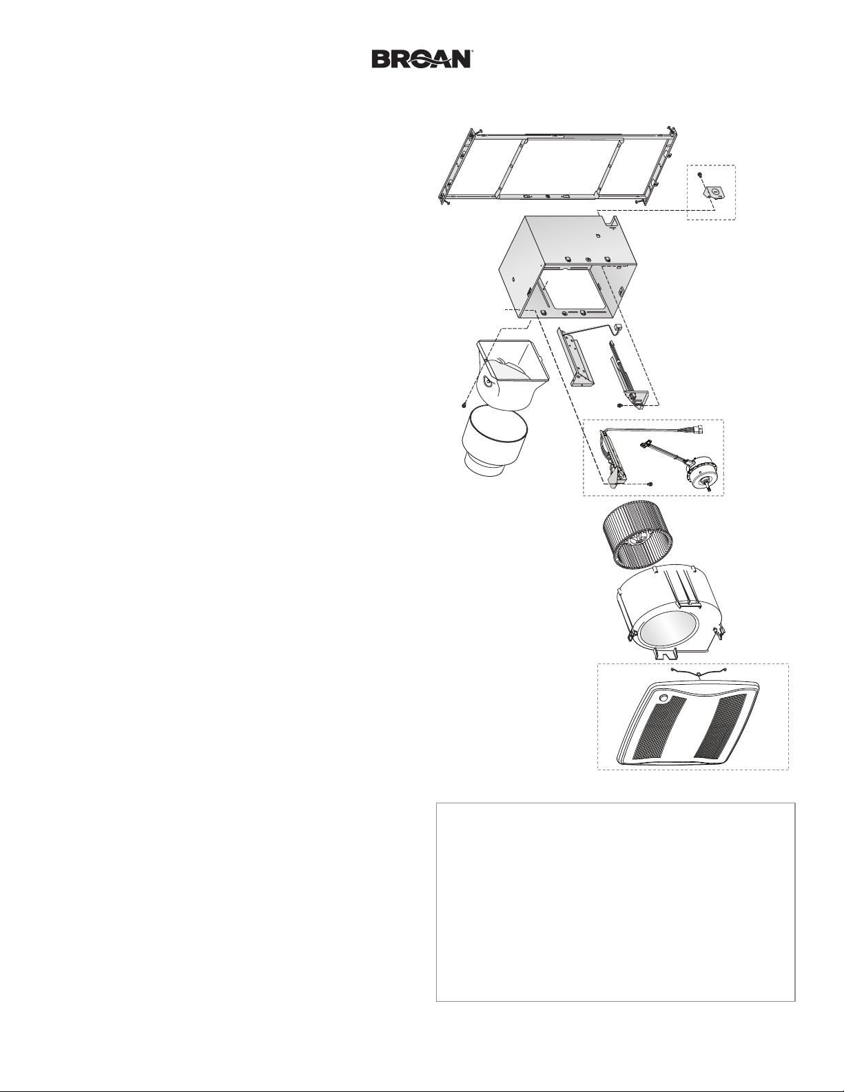
Service Parts
1
2
3
5
4
7
6
8
Symptom: Fan seems noisy.
• Check that back draft damper in fan’s Duct Connector
pivots freely. Screws used to attach duct to Duct Connector may prevent damper from opening.
• Check that back draft damper in wall or roof cap pivots
freely. Dampers are sometimes mistakenly painted shut
or obstructed by bird or insect debris.
Symptom: Fan does not properly ventilate room.
• For spot ventilation, turn both master switch and sensor/
control wall switch ON, so sensor/control operates fan at
certified airflow rate.
• For spot ventilation followed by continuous ventilation,
increase the “TIME” setting of user-adjustable time delay.
• For continuous ventilation, increase “CFM” setting of
user-adjustable airflow rate.
9
Order replacement
parts by Part No.,
not by Key No.
12
Key No. Part No. Description
1 97018349 Mounting Frame
2 97018721 Knockout Plate & Screws
3 97018382 Housing
4 97018472 Wiring Panel/Harness Assembly
5 97018846 Motion Control Assembly
6 1102582 Control Assembly & Motor (ZB80M)
1102583 Control Assembly & Motor (ZB110M)
7 97018331 Duct Connector
8 99111513 6” to 4” Reducer (ZB80M only)
9 99020301 Blower Wheel
10 97019371 Scroll Assembly (ZB80M)
97018768 Scroll Assembly (ZB110M)
11 97018775 Grille Assembly (includes 12)
12 99140208 Grille Spring (2 req’d)
10
11
Page 14

Page 14
Warranty
Broan Ventilation Fan/Lights Limited Warranty
WARRANTY PERIOD: Broan warrants to the original consumer purchaser
of its Broan Ventilation Fan/Light (the “Fan”) that your Fan (excluding lamps/
bulbs) will be materially free from defects in materials or workmanship for a
period of three (3) years from the date of original purchase. The warranty on
the lamps/bulbs provided with the Fan is one (1) year and does not cover
lamp/bulb breakage. This warranty does not cover accessories, such as
speed controls, that may be purchased separately and installed with the Fan.
The limited warranty period for replacement parts, and for Fans repaired or
replaced under this limited warranty, shall continue for the remainder of the
original warranty period.
NO OTHER WARRANTIES: THE FOREGOING WARRANTIES ARE
EXCLUSIVE AND IN LIEU OF ANY OTHER WARRANTIES, EXPRESS OR
IMPLIED. BROAN DISCLAIMS AND EXCLUDES ALL OTHER EXPRESS
WARRANTIES, AND DISCLAIMS AND EXCLUDES ALL WARRANTIES
IMPLIED BY LAW, INCLUDING WITHOUT LIMITATION THOSE OF
MERCHANTABILITY AND FITNESS FOR A PARTICULAR PURPOSE. TO
THE EXTENT THAT APPLICABLE LAW PROHIBITS THE EXCLUSION
OF IMPLIED WARRANTIES, THE DURATION OF ANY APPLICABLE
IMPLIED WARRANTY IS LIMITED TO THE PERIOD SPECIFIED FOR THE
EXPRESS WARRANTY. Some states do not allow limitations on how long an
implied warranty lasts, so the above limitation may not apply to you. Any oral
or written description of the Fan is for the sole purpose of identifying it and
shall not be construed as an express warranty.
REMEDY: During the applicable limited warranty period, Broan will, at its
option, provide replacement parts for, or repair or replace, without charge,
any Fan or part thereof, to the extent Broan finds it to be covered by and in
breach of this limited warranty. Broan will ship the repaired or replaced Fan
or replacement parts to you at no charge. You are responsible for all costs
for removal, reinstallation and shipping, insurance or other freight charges
incurred in the shipment of the Fan or part to Broan. This warranty does not
cover (a) normal maintenance and service, (b) normal wear and tear, (c) any
Fans or parts which have been subject to misuse, abuse, abnormal usage,
negligence, accident, improper or insufficient maintenance, storage or repair
(other than repair by Broan), (d) damage caused by faulty installation, or
installation or use contrary to recommendations or instructions, (e) any Fan
that has been moved from its original point of installation, (f) damage caused
by environmental or natural elements, (g) damage in transit, (h) natural wear
of finish, (i) Fans in commercial or nonresidential use, or (j) damage caused
by fire, flood or other act of God. This warranty covers only Fans sold in the
United States or through U.S. distributors authorized by Broan.
EXCLUSION OF DAMAGES: BROAN’S OBLIGATION TO PROVIDE
REPLACEMENT PARTS, OR REPAIR OR REPLACE, AT BROAN’S
OPTION, SHALL BE YOUR SOLE AND EXCLUSIVE REMEDY UNDER
THIS LIMITED WARRANTY AND BROAN’S SOLE AND EXCLUSIVE
OBLIGATION. BROAN SHALL NOT BE LIABLE FOR INCIDENTAL,
INDIRECT, CONSEQUENTIAL OR SPECIAL DAMAGES ARISING OUT
OF OR IN CONNECTION WITH THE FAN, ITS USE OR PERFORMANCE.
Incidental damages include but are not limited to such damages as loss of
time and loss of use. Consequential damages include but are not limited to
the cost of repairing or replacing other property which was damaged if the
Fan does not work properly.
Some states do not allow the exclusion or limitation of incidental or
consequential damages, so the above limitation or exclusion may not apply
to you. This warranty gives you specific legal rights, and you may also have
other rights, which vary from state to state.
This warranty supersedes all prior warranties and is not transferable from the
original consumer purchaser.
BROAN SHALL NOT BE LIABLE TO YOU, OR TO ANYONE CLAIMING
UNDER YOU, FOR ANY OTHER OBLIGATIONS OR LIABILITIES,
INCLUDING, BUT NOT LIMITED TO, OBLIGATIONS OR LIABILITIES
ARISING OUT OF BREACH OF CONTRACT OR WARRANTY,
NEGLIGENCE OR OTHER TORT OR ANY THEORY OF STRICT LIABILITY,
WITH RESPECT TO THE FAN OR BROAN’S ACTS OR OMISSIONS OR
OTHERWISE.
This warranty covers only replacement or repair of defective Fans or parts
thereof at Broan’s main facility and does not include the cost of field service
travel and living expenses.
Any assistance Broan provides to or procures for you outside the terms,
limitations or exclusions of this limited warranty will not constitute a waiver
of such terms, limitations or exclusions, nor will such assistance extend or
revive the warranty.
Broan will not reimburse you for any expenses incurred by you in repairing
or replacing any defective Fan, except for those incurred with Broan’s prior
written permission.
HOW TO OBTAIN WARRANTY SERVICE: To qualify for warranty service,
you must (a) notify Broan at the address or telephone number stated below
within seven (7) days of discovering the covered defect, (b) give the model
number and part identification and (c) describe the nature of any defect in
the Fan or part. At the time of requesting warranty service, you must present
evidence of the original purchase date.
Broan, 926 West State Street, Hartford, WI 53027
(1-800-637-1453)
www.broan.com
If you must send the Fan or part to Broan, as instructed by Broan, you must
properly pack the Fan or part—Broan is not responsible for damage in transit.
ZB80M n ZB110M Installation Guide
99045844B
Page 15

LEA Y CONSERVE ESTAS INSTRUCCIONES
Aviso al instalador: Deje esta guía con el dueño de la casa.
Registre su producto en línea en www.broan.com/register.
ZB80M n ZB110M
X2 | Ventilador de
velocidad múltiple con
sensor de movimiento
GUÍA DE INSTALACIÓN
Fácil instalación en construcciones
nuevas y en aplicaciones de conversión.
Índice
Advertencias y precauciones 2
Instalación típica 2
Instalación en una construcción nueva 3
Instalación de conversión 7
Funcionamiento 12
Limpieza y mantenimiento 12
Resolución de problemas 12
Piezas de servicio 13
Garantía 14
Page 16

Página 2
Guía de instalación del ventilador ZB80M n ZB110M
ADVERTENCIA
PARA REDUCIR EL RIESGO DE INCENDIOS, DESCARGAS
ELÉCTRICAS O LESIONES PERSONALES, OBSERVE LAS SIGUIENTES
PRECAUCIONES:
1. Use la unidad solo de la manera indicada por el fabricante. Si tiene
preguntas, comuníquese con el fabricante a la dirección o al número
telefónico que se incluye en la garantía.
2. Antes de dar servicio a la unidad o de limpiarla, interrumpa el suministro
eléctrico en el panel de servicio y bloquee los medios de desconexión
del servicio para evitar que la electricidad se reanude accidentalmente.
Cuando no sea posible bloquear los medios de desconexión del
servicio, fije firmemente una señal de advertencia (como una etiqueta)
en un lugar visible del panel de servicio.
3. El trabajo de instalación y el cableado eléctrico deben estar a cargo de
un personal capacitado, de acuerdo con todos los códigos y normas
correspondientes, incluidos los códigos y normas de construcción
específicos sobre protección contra incendios.
4. Es necesario que haya suficiente aire para que se lleve a cabo una
combustión y una extracción adecuadas de los gases a través del tubo
de humos (chimenea) del equipo quemador de combustible, con el fin
de evitar el contratiro. Siga las directrices y las normas de seguridad
del fabricante del equipo de calefacción, como las publicadas por la
Asociación Nacional de Protección contra Incendios (National Fire
Protection Association, NFPA), la Sociedad Americana de Ingenieros
de Calefacción, Refrigeración y Aire Acondicionado (American Society
for Heating, Refrigeration and Air Conditioning Engineers, ASHRAE) y
las autoridades de los códigos locales.
5. Al cortar o perforar a través de la pared o del cielo raso, tenga cuidado
de no dañar el cableado eléctrico ni otros servicios ocultos.
6. Los ventiladores con conductos siempre se deben conectar hacia
elexterior.
7. Use solamente un interruptor de ENCENDIDO/APAGADO, un
temporizador mecánico o un control de relé-interruptor.
8. Esta unidad puede instalarse sobre una tina o ducha siempre que se
conecte a un GFCI (interruptor accionado por pérdida de conexión a
tierra) en un circuito de derivación protegido.
9. Esta unidad debe estar conectada a tierra.
PRECAUCIÓN
1. Solo para usarse como medio de ventilación general. No debe usarse
para la extracción de materiales o vapores peligrosos o explosivos.
2. Este producto está diseñado para instalarse solamente en un cielo
raso plano. El sensor no funcionará de forma fiable si el producto no
se instala en un cielo raso plano. NO MONTE ESTE PRODUCTO EN
LA PARED.
3. Para evitar daños a los cojinetes del motor y rotores ruidosos o
desbalanceados, mantenga la unidad de potencia protegida contra
rociados de yeso, polvos de construcción, etc.
4. Lea la etiqueta de especificaciones del producto para ver información
y requisitos adicionales.
NO USAR EL PRODUCTO EN UN ÁREA DE COCINA
No instale el equipo sobre o dentro de esta área
45° 45°
Equipo
de cocina
Piso
Instalación típica
AISLAMIENTO*
• La instalación es la misma para:
ELÉCTRICO*
Vigas Vigas en “I” Cerchas
• Cabe en una construcción de cielo raso de
2 x 8 pulg. (5.1 x 20.3 cm)
• Ajustes ilimitados de la posición del
ventilador entre las vigas de 14 a 24 pulg.
(35.6 a 61 cm) en el centro.
Selle las
separaciones
alrededor de
la cubierta.
Los conductos desde este ventilador hacia el exterior del edificio tienen un gran efecto sobre el flujo de aire, el ruido y el uso de energía
del ventilador. Utilice el tramo de conductos más corto y recto posible para obtener un desempeño óptimo y evite instalar el ventilador
con conductos menores que los recomendados. El aislamiento alrededor de los conductos puede reducir la pérdida de energía e inhibir
el desarrollo de moho. Los ventiladores instalados en conductos existentes podrían no obtener el flujo de aire nominal.
Para un mejor desempeño, se recomienda utilizar conductos metálicos redondos y rígidos de 6 pulg. (15.2 cm).
(Colóquelo alrededor y
sobre la cubierta del
CUBIERTA DEL
VENTILADOR
CABLE
CONDUCTO
REDONDO*
*Se compra por
separado.
ventilador).
Selle con
las uniones
conductos.
cinta
de los
O
CODOS
REDONDOS*
TAPA DE
TECHO *
(con regulador
de tiro integrado)
Mantenga
cortos
los tramos
de conductos.
TAPA DE
PARED *
(con regulador
de tiro integrado)
Page 17

Página 3
Instalación en una construcción nueva
Guía de instalación del ventilador ZB80M n ZB110M
Herramientas necesarias
• Destornillador eléctrico con cabeza Phillips
• Destornillador Phillips
• Destornillador de cabeza plana
• Alicates
• Desforrador de cables
• Cortador de cables
Materiales necesarios
• Se recomienda utilizar conductos metálicos redondos de 6 pulg. (15.2 cm) para
• Tapa de techo o tapa de pared (se recomienda que tenga regulador de tiro integrado)
• Cinta para sellar las conexiones de los conductos
• Cableado eléctrico y suministros según los requisitos de los códigos locales
Saque el producto de su empaque
1
La bolsa de piezas
contiene la placa
de agujero ciego y
seis (6) tornillos
obtener un desempeño óptimo.
Aunque el uso de otros sistemas de conductos es aceptable, puede afectar
aldesempeño.
Retire la cubierta protectora del
empaque. Proceda con el paso 6.
Saque la hoja
de instrucciones
Instale
2
el marco
de montaje
2
1
4
3
Page 18

Página 4
Instalación en una construcción nueva
Acople y fije
3
la cubierta
1
2
Acople
a presión
Guía de instalación del ventilador ZB80M n ZB110M
4
Tornillos de la bolsa de piezas
3
Acople el conector de conducto y los conductos
4
Las bridas superior e inferior se
instalan por fuera de la cubierta
Introduzca la pestaña en
la ranura del interior de
la cubierta
1
Conductos de
6 pulg. (15.2 cm)
Cinta
Conductos de
3
4 pulg. (10.2 cm)
Cinta
Coloque la cubierta entre
las vigas y doble el canal
a ambos lados del marco
de montaje para fijar
la cubierta en su lugar.
No doble la cubierta.
Tornillo de
2
la bolsa
de piezas
Cinta
Reductor de 6 a 4 pulg (15.2 a 10.2 cm) (para modelo ZB80M solamente)
Page 19

Página 5
Guía de instalación del ventilador ZB80M n ZB110M
Instalación en una construcción nueva
Conecte los cables e instale la placa de agujero ciego
5
• Tienda el cable eléctrico de 120 VCA hasta el lugar de la instalación.
• Use conectores aprobados por UL para fijar el cableado a la placa de agujero ciego incluida en la bolsa de piezas.
• Conecte los cables tal como se ilustra en el diagrama de cableado.
1
Acople la abrazadera para
cables a la placa de agujero
ciego. La placa de agujero ciego
se monta en el exterior de la
cubierta y puede orientarse en la
dirección que se desee.
Conecte los cables
2
3
4
Tornillo de
la bolsa
de piezas
TIERRA
120 VCA
LÍNEA DE
ENTRADA
INTERRUPTOR
MAESTRO DE
ENCENDIDO/
BLANCO
NEGRO
APAGADO*
* Se compra por separado
INTERRUPTOR
MAESTRO
INTERRUPTORES DE PARED
MULTIFUNCIONALES O ESTÁNDAR
NEGRO
BLANCO
INTERRUPTOR
DE CONTROL/
SENSOR*
INTERRUPTOR
DE ENCENDIDO
MANUAL*
CAJA DEL INTERRUPTOR
SENSOR/
CONTROL
ROJO
AZUL
ENCENDIDO
MANUAL
NARANJA
CAFÉ
TIERRA
(Verde o sin aislamiento)
LÍNEA DE ENTRADA
DE 120 VCA
TIERRA
BLANCO
NEGRO
AZUL
ROJO
14/4
(SI SE UTILIZAN
TODAS
LAS OPCIONES DE
INTERRUPTORES
DE PARED)
PLACA DE
AGUJERO CIEGO
NEGRO
ROJO
CAFÉ
NARANJA
RECEPTÁCULOS
BLANCO
• Vea los detalles
de la sección
FUNCIONAMIENTO
en la página 26.
VENTILADOR
NEGRO
• El interruptor
MAESTRO enciende
y apaga el sistema
del ventilador para
SENSOR/
CONTROL
fines de limpieza y
mantenimiento.
• El interruptor del
SENSOR/CONTROL
enciende/apaga
el funcionamiento
automático del control
de movimiento.
• El interruptor de ENCENDIDO
MANUAL aumenta directamente el
funcionamiento del ventilador a un
índice certificado de flujo de aire.
• Se pueden combinar los interruptores
MAESTRO y SENSOR/CONTROL
(vea la página 24).
• El interruptor MAESTRO, junto o por
separado del interruptor SENSOR/
CONTROL, se puede colocar donde
no se pueda tener acceso fácilmente
para uso diario; tal vez sea necesario
etiquetarlo y situarlo donde no se
pueda encender sin ser visto desde
el ventilador para cumplir con los
códigos locales y nacionales.
Page 20

Página 6
Instalación en una construcción nueva
Inserte la cubierta
6
` protectora y
finalice el cielo
raso
• Instale el material del
cielo raso.
• Recorte alrededor de
la cubierta.
PRECAUCIÓN
PARA PREVENIR DAÑOS EN
EL MOTOR/CONTROL:
Si el motor estaba desconectado, se debe desconectar la
electricidad (vea la página 16, ADVERTENCIA, punto 2) antes
de insertar los enchufes del motor en el conjunto de control.
Guía de instalación del ventilador ZB80M n ZB110M
La cubierta protege
la unidad durante la
construcción. Retírela
antes de instalar
la rejilla.
Instale la rejilla
7
Conecte
el sensor
Consulte la página 12 para obtener información sobre el funcionamiento, limpieza, mantenimiento y resolución de problemas.
1
2
3
Page 21

Página 7
Instalación de conversión
Guía de instalación del ventilador ZB80M n ZB110M
Herramientas necesarias
• Destornillador eléctrico con cabeza Phillips
• Destornillador Phillips
• Destornillador de cabeza plana
• Alicates
• Desforrador de cables
• Cortador de cables
• Regla
• Lápiz
• Sierra para panel de yeso
• Martillo de uñas o pata de cabra
• Navaja utilitaria
Materiales necesarios
• Cinta para sellar las conexiones de
los conductos
• Los conductos rígidos existentes requerirán la
adición de un tramo corto de conducto flexible
• Cableado eléctrico y suministros según los
requisitos de los códigos locales
Saque el producto de su empaque
1
Saque la hoja de
instrucciones
La bolsa de piezas
contiene la placa
de agujero ciego y
seis (6) tornillos
Retire la cubierta protectora del
empaque. Proceda con el paso 12.
Apague la unidad
2
ADVERTENCIA
Antes de quitar la unidad existente, interrumpa el suministro eléctrico en el panel de servicio y bloquee los medios de
desconexión del servicio para evitar que la electricidad se reanude accidentalmente. Cuando no sea posible bloquear
los medios de desconexión del servicio, fije firmemente una señal de advertencia (como una etiqueta) en un lugar
visible del panel de servicio.
Agrande la abertura del cielo raso y retire el ventilador existente
3
12 pulg. (30.5 cm)
1
11 pulg. (27.9 cm)
paralelo a las vigas
Conductos existentes y
cableado en su lugar
Examine el cableado
4
Examine el cableado existente para asegurarse de que no esté dañado. Si encuentra algún daño,
NO CONTINÚE CON LA INSTALACIÓN de este producto. Encargue la reparación a personas debidamente capacitadas.
2
Page 22

Página 8
Instalación de conversión
Retire el conjunto del ventilador
5
2
Guía de instalación del ventilador ZB80M n ZB110M
1
Ponga a un
lado el conjunto
del ventilador
Ambos lados
Retire el panel de cableado
6
Ponga a
un lado
el tornillo
1
2
3
Ponga a un lado
el panel
de cableado
3
Inserte
7
el marco
de montaje
4
3
1
Saque los tornillos del
marco de montaje y
póngalos a un lado
5
2
Doble hacia arriba
lascuatro pestañas
Page 23

Página 9
Instalación de conversión
Sujete
8
el marco
de montaje
Cubierta a presión
9
Guía de instalación del ventilador ZB80M n ZB110M
Tornillos
extraídos en
el paso 7
2
10
Tire de los
conductos
existentes
hacia el
interior de
la cubierta
Conductos de
6 pulg. (15.2 cm)
1
Tire del cableado existente hacia el
interior de la cubierta a medida que lo
inserta en el marco de montaje
Acople
a presión
Acople el conector de conductos y los conductos
4
1
2
Cinta
Conductos de
4 pulg. (10.2 cm)
Cinta
Cinta
Tornillo de
la bolsa
de piezas
3
Introduzca la
pestaña en la
ranura del interior
de la cubierta
Reductor de 6 a 4 pulg (15.2 a 10.2 cm) (para modelo ZB80M solamente)
Page 24

Página 10
Instalación de conversión
Instale la placa de agujero ciego, conecte los cables y reinstale
11
el panel de cableado
• Use conectores aprobados por UL para fijar el cableado a la placa de agujero ciego incluida en la bolsa de piezas.
• Conecte los cables tal como se ilustra en el diagrama de cableado.
Acople la abrazadera para cables
1
Tornillo de
la bolsa
de piezas
a la placa de agujero ciego.
La placa de agujero ciego
se monta en el
interior de
la cubierta y
puede orientarse
en la dirección
que se desee.
2
Guía de instalación del ventilador ZB80M n ZB110M
Tornillo
extraído en
el paso 6
5
6
4
Conecte
3
los cables
• Vea los detalles de la sección
FUNCIONAMIENTO en la página 26.
• El interruptor MAESTRO enciende
el sistema de ventilador junto con
el control de movimiento, y los
apaga para fines de limpieza y
mantenimiento.
• El interruptor MAESTRO se puede
colocar donde no se pueda tener
acceso fácilmente para uso diario;
tal vez sea necesario etiquetarlo
y colocarlo donde no se pueda
encender sin ser visto desde el
ventilador para cumplir con los
códigos locales y nacionales.
NEGRO
120 VCA
LÍNEA DE
ENTRADA
BLANCO
TIERRA
NEGRO
BLANCO
INTERRUPTOR
* Se compra por separado
INTERRUPTOR
DE PARED
MAESTRO
ROJO
AZUL
DE PARED
CAJA DEL INTERRUPTOR
MAESTRO*
LÍNEA DE ENTRADA
DE 120 VCA
NEGRO
BLANCO
TIERRA
14/2
TIERRA
(Verde
o sin aislamiento)
PLACA DE
AGUJERO CIEGO
NEGRO
ROJO
VENTILADOR
NEGRO
CAFÉ
SENSOR/
CONTROL
NARANJA
BLANCO
RECEPTÁCULOS
Page 25

Página 11
Instalación de conversión
Reinserte y fije el conjunto del ventilador
12
PRECAUCIÓN
Debe desconectar la electricidad (vea la página 16, ADVERTENCIA, punto 2) antes de insertar los enchufes
del motor en el conjunto de control.
Guía de instalación del ventilador ZB80M n ZB110M
PARA PREVENIR DAÑOS EN EL MOTOR/CONTROL:
13
Conecte
el sensor
Instale la rejilla
1
1
2
2 3
Tornillos de la bolsa de piezas
Si es necesario realizar reparaciones en el cielo
raso, coloque el protector en la cubierta después
de haber fijado el conjunto del ventilador.
Consulte el paso 6 sobre la instalación en una
construcción nueva. Retire la cubierta protectora
antes de instalar la rejilla.
3
Page 26

Página 12
Guía de instalación del ventilador ZB80M n ZB110M
ADVERTENCIA Antes de dar servicio a la unidad o de
limpiarla, interrumpa el suministro eléctrico en el panel de servicio y bloquee
los medios de desconexión del servicio para evitar que la electricidad se
reanude accidentalmente. Cuando no sea posible bloquear los medios de
desconexión del servicio, fije firmemente una señal de advertencia (como una
etiqueta) en un lugar visible del panel de servicio.
Funcionamiento
Es normal que este ventilador para tomar aproximadamente 5 segundos para empezar a
correr después de que se encienda.
Modos
(Como referencia, los diagramas de cableado se encuentran en las páginas 19 y
24).
Ventilación continua:
1. Encienda el interruptor de pared maestro (asegúrese de que todos los demás
interruptores de pared están apagados).
2. El ventilador funciona a un índice nominal de flujo de aire ajustable por el
usuario.
Detección de movimiento:
1. Si el interruptor de pared maestro todavía no está encendido, enciéndalo.
2.
Encienda el interruptor de pared del sensor/control. Es posible que algunas
instalaciones no dispongan de un interruptor de pared independiente para el
sensor/control, y que este
maestro.
3. El ventilador funciona a un índice certificada de flujo de aire y el sensor detecta
el movimiento.
4. Cuando no se detecte más movimiento, el ventilador entra a modo de retardo de
tiempo. (Vea má abajo.)
Encendido manual (se debe instalar un interruptor de pared opcional para el encendido
manual):
1. Encienda los interruptores de pared principal y de encendido manual (el interruptor de
pared del sensor/control puede estar encendido o apagado).
2. El ventilador funciona a un índice certificada de flujo de aire.
3. Cuando el interruptor de pared de encendido manual está apagado, el ventilador pasa al
modo de retardo de tiempo.
Retardo de tiempo:
El ventilador continúa funcionando a una velocidad de flujo de aire certificado hasta que haya
pasado por el usuario ajustable retardo de tiempo, y luego se vuelve fan de cuadal de aire
velocidad ajustable por el usuario.
interruptor esté combinado con un interruptor de pared
Limpieza y
mantenimiento
PRECAUCIÓN
PARA PREVENIR DAÑOS EN EL
MOTOR/CONTROL:
NO retire el enchufe del motor para
detener el giro del motor.
La electricidad debe estar desconectada
(vea la ADVERTENCIA en la parte
superior izquierda de esta página) antes
de retirar o insertar el enchufe del motor
en el conjunto de control.
Para limpiarlo
Para lograr un funcionamiento silencioso y
eficiente, además de una larga vida útil y una
apariencia atractiva, retire la rejilla y aspire
el interior de la unidad con un accesorio del
cepillo para quitar el polvo.
No use sprays limpiadores, solventes ni agua
en el sensor o cerca del mismo.
El motor está permanentemente lubricado
y nunca necesitará aceite. Si el motor hace
ruidos excesivos o inusuales, reemplace el
conjunto de control y el motor.
Cómo ajustar el índice de flujo de aire ajustable por el
usuario*
Utilizando un destornillador pequeño de cabeza plana, gire con cuidado el control
de ajuste CFM (pies cúbicos por minuto) hasta que la flecha apunte al índice de
flujo de aire deseado.
Cómo ajustar el tiempo de espera ajustable por el usuario*
Utilizando un destornillador pequeño de cabeza plana, gire con cuidado el control
de ajuste del TIEMPO hasta que la flecha apunte al tiempo de retardo deseado,
expresado en minutos.
* Los controles ajustables por el usuario están situados en una esquina de la
cubierta del ventilador, detrás de la rejilla.
Controles ajustables por el usuario del ZB80M
Controles ajustables por el usuario del ZB110M
Para APAGAR el ventilador
APAGUE el interruptor maestro.
Page 27

Página 13
Guía de instalación del ventilador ZB80M n ZB110M
Resolución de problemas
Antes de continuar, desconecte la alimentación, como se indica
en las secciónes de ADVERTENCIA y PRECAUTION de la página
anterior.
Síntoma: El ventilador no funciona.
• Compruebe si hay un fusible o un interruptor automático
abierto en el panel de servicio del edificio.
• Asegúrese de que los dos (2) conectores de enchufe del motor
y de su control estén bien afianzados en su lugar.
• Asegúrese de que los dos (2) conectores de enchufe del
sensor y de su control estén bien afianzados en su lugar.
• Compruebe que la rueda del ventilador gire sin obstrucciones.
Síntoma: El modo de movimiento no hace funcionar el
ventilador al índice nominal de flujo de aire.
• Asegúrese de que los dos (2) conectores de enchufe del
sensor y de su control estén bien afianzados en su lugar.
Síntoma: El ventilador funciona de forma errática.
•
Compruebe que la rueda del ventilador esté firmemente
acoplada al eje del motor y que ambos giren sin obstrucciones.
Síntoma: El ventilador hace demasiado ruido.
• Compruebe que el regulador de tiro invertido del conector de
conductos del ventilador gire sin obstrucciones. Los tornillos
utilizados para afianzar el conducto al conector de conductos
pueden impedir que el regulador de tiro se abra.
• Compruebe que el regulador de tiro invertido del conector
de conductos de la tapa de techo o de pared gire sin
obstrucciones. Estos reguladores suelen cerrarse
accidentalmente después de ser pintados o suelen obstruirse
con pájaros o restos de insectos.
Piezas de servicio
5
7
8
Pida las piezas por
número de pieza,
no por número
de clave.
1
2
3
4
6
9
10
Síntoma: El ventilador no ventila adecuadamente la habitación.
• Para ventilar un área específica, ENCIENDA tanto el
interruptor maestro como el interruptor de pared del sensor/
control, para que el sensor/control haga funcionar al índice
nominal de flujo de aire.
• Para ventilar un área específica seguida de ventilación
continua, aumente el nivel de “TIME” (Tiempo) del selector
de tiempo de espera ajustable por el usuario.
• Para una ventilación continua aumente el nivel de “CFM”
correspondiente al índice nominal de flujo de aire ajustable por
el usuario.
12
N.º de N.º de
clave pieza Descripción
1 97018349 Marco de montaje
2 97018721 Placa de agujero ciego y tornillos
3 97018382 Cubierta
4 97018472 Conjunto del panel de cableado/mazo de cables
5 97018846 Conjunto de control de movimiento
6 1102582 Conjunto de control y motor (ZB80M)
1102583 Conjunto de control y motor (ZB110M)
7 97018331 Conector del conducto
8 99111513 Reductor de 6 a 4 pulg (15.2 a 10.2 cm)
(ZB80M solamente)
9 99020301 Rueda del ventilador
10 97019371 Conjunto del desplazador (ZB80M)
97018768 Conjunto del desplazador (ZB110M)
11 97018775 Conjunto de la rejilla (incluye 12)
12 99140208 Resorte de la rejilla (se requieren 2)
11
Page 28

Página 14
Garantía
Garantía limitada para las luces/ventilador para ventilación Broan
PERÍODO DE LA GARANTÍA: Broan le garantiza al comprador consumidor
original de su lámpara/ventilador para ventilación Broan (el “Ventilador”) que
su ventilador (a excepción de lámparas/lamparillas) no presentará defectos de
material o de mano de obra durante un período de tres (3) años a partir de la
fecha de la compra original. La garantía para las lámparas/lámparas de noche
que vienen con el Ventilador es de un (1) año y no cubre la rotura de las mismas.
Esta garantía no cubre accesorios tales como controles de velocidad que pueden
adquirirse por separado y que se instalan con el Ventilador.
El período de garantía limitada para los repuestos y para los Ventiladores
reparados o reemplazados bajo esta garantía limitada continuará durante el
período restante de la garantía original.
AUSENCIA DE OTRAS GARANTÍAS: LAS SIGUIENTES GARANTÍAS SON
EXCLUSIVAS Y SE RELACIONAN CON TODA OTRA GARANTÍA EXPRESA
O IMPLÍCITA. BROAN RENUNCIA Y EXCLUYE TODA OTRA GARANTÍA
EXPRESA Y RENUNCIA Y EXCLUYE TODA GARANTÍA QUE EXIJA LA LEY,
INCLUYENDO PERO NO LIMITÁNDOSE A AQUELLAS RELACIONADAS CON
LA COMERCIABILIDAD Y LA APTITUD PARA UN FIN EN PARTICULAR. EN
TANTO LA LEY CORRESPONDIENTE PROHÍBA LA EXCLUSIÓN DE LAS
GARANTÍAS IMPLÍCITAS, LA DURACIÓN DE TODA GARANTÍA IMPLÍCITA
APLICABLE SE LIMITA AL PERÍODO ESPECIFICADO PARA LA GARANTÍA
EXPRESA. Algunos estados no permiten limitaciones sobre cuál es la duración
de una garantía implícita, de modo que la limitación antes mencionada puede no
aplicarse a su caso. Toda descripción escrita u oral del Ventilador es al sólo fin de
identificarlo y no deberá tomarse como una garantía expresa.
COMPENSACIÓN: Durante el transcurso del período aplicable de la garantía
limitada, Broan, a su discreción, proporcionará repuestos, reparación o
reemplazo, en forma gratuita, para cualquier Ventilador o cualquiera de sus
piezas, en tanto Broan considere que está cubierto por y en violación de esta
garantía limitada. Broan le enviará el Ventilador reparado o su reemplazo o
los repuestos en forma gratuita. Usted es responsable de los costos de retiro,
reinstalación y envío, seguros y otros cargos por flete que se generen durante
el transporte del Ventilador o del repuesto a Broan. Esta garantía no cubre (a) el
mantenimiento y el servicio normales, (b) el desgaste normal, (c) todo Ventilador
o repuesto sometido a mal uso, abuso, uso anormal, negligencia, accidente,
mantenimiento inadecuado o insuficiente, conservación o reparación (que no
sea la reparación realizada por Broan, (d) daños provocados por instalación
defectuosa o instalación o uso contrario a las recomendaciones o instrucciones,
(e) todo Ventilador que se haya trasladado del punto original de instalación, (f)
daño provocado por elementos naturales o ambientales, (g) daño durante el
transporte, (h) desgaste natural del acabado, (i) Ventiladores en uso comercial o
no residencial o (j) daño provocado por incendio, inundación u otro caso fortuito.
Esta garantía cubre sólo a los Ventiladores que se venden en los Estados Unidos
o a través de representantes de los Estados Unidos autorizados por Broan.
EXCLUSIÓN DE DAÑOS: LA OBLIGACIÓN DE BROAN DE PROPORCIONAR
REPUESTOS O LA REPARACIÓN O EL REEMPLAZO, A DISCRECIÓN DE
BROAN, SERÁ LA ÚNICA Y EXCLUSIVA COMPENSACIÓN BAJO EL AMPARO
DE ESTA GARANTÍA LIMITADA Y LA ÚNICA Y EXCLUSIVA OBLIGACIÓN DE
BROAN. BROAN NO SERÁ RESPONSABLE DE DAÑOS INCIDENTALES,
INDIRECTOS, EMERGENTES O ESPECIALES QUE SURJAN DE O EN
CONEXIÓN CON EL VENTILADOR, SU USO O FUNCIONAMIENTO. Los
daños incidentales incluyen, pero no se limitan a, daños tales como pérdida de
tiempo o pérdida del uso. Los daños emergentes incluyen pero no se limitan al
costo de la reparación o reemplazo de otra propiedad que haya sufrido daños en
caso del mal funcionamiento del Ventilador.
Algunos estados no permiten la exclusión o la limitación de los daños incidentales
o emergentes, de modo que la limitación o la inclusión antes mencionada puede
no aplicarse a su caso. Esta garantía le otorga derechos legales específicos y
usted también podrá gozar de otros derechos que varían según el estado.
Esta garantía reemplaza a todas las garantías anteriores y no es transferible por
el comprador consumidor original.
BROAN NO SERÁ RESPONSABLE ANTE USTED, O ANTE CUALQUIER
PERSONA QUE RECLAME EN SU NOMBRE, DE NINGUNA OTRA
OBLIGACIÓN O RESPONSABILIDAD, QUE INCLUYE, PERO NO SE LIMITA
A, LAS OBLIGACIONES O RESPONSABILIDADES QUE SURJAN DE LA
VIOLACIÓN DEL CONTRATO O DE LA GARANTÍA, NEGLIGENCIA U
OTRO AGRAVIO O CUALQUIER TEORÍA SOBRE LA RESPONSABILIDAD
ESTRICTA, CON RESPECTO AL VENTILADOR O A LOS ACTOS U
OMISIONES U OTROS POR PARTE DE BROAN.
Esta garantía cubre sólo el reemplazo o la reparación de los Ventiladores o
piezas con defectos del mismo en la plana principal de Broan y no incluye los
costos del transporte del servicio en campo ni los gastos de estadía.
Toda asistencia que Broan le brinde o procure fuera de los términos, las
limitaciones o las exclusiones de esta garantía limitada no constituirá una
renuncia a dichos términos, limitaciones o exclusiones ni dicha asistencia
extenderá o revivirá la garantía.
Broan no le reembolsará ningún gasto en el que usted incurra en la reparación
o reemplazo de cualquier Ventilador defectuoso excepto por aquellos en los que
incurra previo a la obtención del permiso por escrito de Broan.
CÓMO OBTENER EL SERVICIO DE LA GARANTÍA: Para calificar para el
servicio de garantía, usted debe (a) notificar a Broan a la dirección o al número
de teléfono que figura a continuación dentro de los siete (7) días de haber
descubierto el defecto cubierto, (b) brindar el número de modelo y la identificación
de la pieza y (c) describir la naturaleza de cualquier defecto del Ventilador o de la
pieza. A la hora de solicitar el servicio de garantía, usted debe presentar prueba
de la fecha original de la compra.
Broan, 926 West State Street, Hartford, WI 53027
(1-800-637-1453)
www.broan.com
Si usted debe enviar el Ventilador o la pieza a Broan, según las indicaciones de
Broan, debe embalar el Ventilador o la pieza en forma adecuada. Broan no es
responsable de los daños ocasionados durante el transporte.
Guía de instalación del ventilador ZB80M n ZB110M
99045844B
Page 29

LISEZ ET CONSERVEZ CES INSTRUCTIONS
À l’attention de l’installateur: laissez ce guide chez le client.
Enregistrez votre produit en ligne sur www.broan.ca/register.asp
ZB80M n ZB110M
X2 | Ventilateur multivitesse
avec détecteur
de mouvement
GUIDE D’INSTALLATION
Installation facile,
lors de construction
neuve ou de rénovations
Table des matières
Avertissementset mises en garde 2
Installation type 2
Installation dans une construction neuve 3
Installation lors de rénovation 7
Fonctionnement 12
Nettoyage et entretien 12
Dépannage 12
Pièces de rechange 13
Garantie 14
Page 30

Page 2
!
ZB80M n ZB110M Guide d’installation
AVERTISSEMENT
POUR DIMINUER LE RISQUE D’INCENDIE, D’ÉLECTROCUTION OU
DE BLESSURE, RESPECTER LES PRÉCAUTIONS CI-DESSOUS:
1. N’utilisez cet appareil que de la manière prévue par son fabricant.
Si vous avez des questions, communiquez avec le fabriquant à
l’adresse ou au numéro de téléphone indiqués dans la garantie.
2. Avant toute intervention sur l’appareil ou nettoyage de celui-ci,
couper l’alimentation électrique au tableau de distribution et
verrouiller le dispositif de sectionnement pour empêcher toute
remise sous tension accidentelle. S’il est impossible de verrouiller
le dispositif de sectionnement, y fixer solidement et de manière
visible un dispositif d’affichage (par ex. : une étiquette).
3. Les travaux d’installation et de raccordement électrique doivent
obligatoirement être effectués par du personnel qualifié,
conformément aux codes et normes applicables, y compris les
codes et normes relatifs aux constructions résistantes au feu.
4. Une quantité suffisante d’air est nécessaire pour assurer la
bonne combustion et l’évacuation par la cheminée des gaz
produits par les appareils brûlant du combustible, pour éviter tout
refoulement. Respecter les recommandations du fabriquant de
l’appareil et les normes de sécurité comme celles publiées par la
National Fire Protection Association (NFPA), l’American Society
for Heating, Refrigeration and Air Conditioning Engineers et les
autorités locales responsables des codes.
5. Lorsque vous coupez un mur ou un plafond, prenez garde de ne
pas endommager les fils électriques ou autres installations qui
pourraient y être dissimulés.
6. Les ventilateurs avec conduit doivent toujours évacuer l’air
à l’extérieur.
7. N’utilisez qu’un interrupteur MARCHE/ARRÊT, une minuterie
mécanique ou une commande à relais.
8. Cet appareil convient à une installation au-dessus de la baignoire
ou de la douche lorsqu’il est relié à un circuit protégé par un
disjoncteur de fuite à la terre (DDFT).
9. Cet appareil doit obligatoirement être mis à la terre.
ATTENTION
1. Réservé exclusivement à la ventilation générale. Ne pas utiliser
pour évacuer des matières ou des vapeurs dangereuses
ou explosives.
2. Ce produit est conçu pour être installé dans des plafonds plats.
Le détecteur ne pourra fonctionner de façon fiable si ce produit est
installé dans un plafond en pente. NE PAS MONTER CE PRODUIT
DANS UN MUR.
3. Pour éviter d’endommager les paliers du moteur et les roues de
devenir bruyantes et (ou) mal équilibrées, garder votre appareil
à l’abri des poussières de gypse, de construction, etc.
4. Consulter l’étiquette des caractéristiques sur le produit pour
plus de renseignements ou exigences.
NE PAS UTILISER DANS UNE CUISINE
Ne pas installer au-dessus ou à l’intérieur de cette zone
45° 45°
Appareil
de cuisson
Plancher
Instalation type
• L’installation est identique pour:
Solive Poutrelle Fermes
en « I » de toit
• Convient à un plafond construit
en 2 po x 8 po.
• Le ventilateur s’installe n’importe où entre
les solives, de 14 po à 24 po d’entraxe.
Les conduits allant de ce ventilateur jusqu’à l’extérieur de l’habitation ont une grande influence sur le débit d’air, le bruit du
ventilateur et sa consommation d’énergie. Pour obtenir le meilleur rendement, utilisez les conduits les plus courts et les
plus droits que possible et évitez d’utiliser des conduits plus petits que ceux recommandés. L’isolation des conduits peut
contribuer à réduire les pertes d’énergie et éviter la prolifération de moisissures. Les ventilateurs installés sur d’anciens
conduits pourraient ne pas produire leur débit d’air nominal.
Pour un rendement optimal, il est recommandé d’utiliser des conduits métalliques ronds de 15.2 cm (6 po) de diamètre.
ISOLATION*
(Répartir autour
et au-dessus du boîtier
du ventilateur.)
BOÎTIER DE
VENTILATEUR
CORDON
D’ALIMENTATION*
Calfeutrer
les espaces
autour du ventilateur.
CONDUIT ROND*
* Vendu séparément.
Sceller les joints
de conduit avec
du ruban adhésif.
OU
COUDES
RONDS*
CAPUCHON
DE TOIT*
(avec
clapet intégré)
Garder le
tracé des
conduits court.
CAPUCHON
MURAL*
(avec clapet intégré)
Page 31

Page 3
Installation dans une construction neuve
ZB80M n ZB110M Guide d’installation
Outils nécessaires
• Tournevis électrique avec embout Phillips
• Tournevis Phillips
• Tournevis à lame plate
• Pinces
• Pince à dénuder
• Pince coupante
Retirer l’emballage
1
Le sachet de
pièces contient
une plaque de
câblage et
six (6) vis.
Matériaux nécessaires
•
Conduit rond en métal de 6 po recommandé pour une meilleure performance.
Du conduit différent est acceptable, au prix d’une performance inférieure.
• Capuchon de toit ou de mur (recommandé avec clapet intégré).
• Ruban adhésif pour l’étanchéité des joints.
• Câblage et fournitures électriques en fonction des exigences du code local.
Découper le masque dans l’emballage.
Voir l’étape 6.
Enlever la feuille
d’instructions.
Installer le cadre
2
de montage
2
1
4
3
Page 32

Page 4
Installation dans une construction neuve
Encliqueter et
3
fixer le boîtier
1
2
Encliqueté!
ZB80M n ZB110M Guide d’installation
4
Vis du sachet de pièces
3
Fixer le raccord de conduit et le conduit
4
Les rebords supérieur et inférieur
vont à l’extérieur du boîtier.
Introduire la languette
dans la fente à l’intérieur
du boîtier.
1
Conduit
de 6po
Ruban
adhésif
Mettre le boîtier en place
entre les solives et
pincer la glissière de
chaque côté du cadre de
montage pour verrouiller
le boîtier en place.
Ne pas pincer le boîtier.
Vis du
2
sachet
de pièces
3
Conduit
de 4po
Ruban
adhésif
Ruban
adhésif
Réducteur de 6 po à 4 po fourni avec certains modèles
Page 33

Page 5
Mise à
RÉCEPTACLES
DE 120 VCA
Installation dans une construction neuve
Raccorder les fils et installer la plaque de câblage
5
• Acheminer les fils 120V CA à l’emplacement de l’installation.
• Raccorder les fils à la plaque de câblage fournie dans le sachet de pièces à l’aide de connecteurs homologués UL.
• Raccorder les fils tel qu’il est indiqué au schéma de câblage.
Fixer le collier à la plaque de
1
câblage. La plaque de câblage
s’installe à l’extérieur du boîtier,
d’un côté comme de l’autre.
Raccorder les fils.
2
la terre
LIGNE
D’ENTRÉE
DE 120 VCA
INTERRUPTEUR
MARCHE/ARRÊT*
BLANC
NOIR
PRINCIPAL
* Acheter séparément
INTERRUPTEUR
CAPTEUR/
PRINCIPAL
INTERRUPTEURS STANDARDS
NOIR
BLANC
INTERRUPTEUR
DE COMMANDE
DU CAPTEUR*
COMMANDE
OU MULTIFONCTION
INTERRUPTEUR
MANUEL*
INTERRUPTEUR
MANUEL-
MARCHE
ROUGE
BLEU
BOÎTIER
D’INTERRUPTEURS
LIGNE D’ENTRÉE
Mise à
la terre
BLANC
NOIR
BLEU
ROUGE
14/4
SI TOUTES
(
LES OPTIONS
D’INTERRUPTEUR
SONT UTILISÉES
ORANGE
BRUN
Mise à la terre
(VERT ou nu)
)
PLAQUE
DE CÂBLAGE
3
NOIR
ROUGE
BRUN
ORANGE
ZB80M n ZB110M Guide d’installation
4
Vis du
sachet
de pièces
BLANC
VENTILATEUR
NOIR
CONTRÔLE
DU CAPTEUR
• Les interrupteurs MAÎTRE et
CAPTEUR/COMMANDE peuvent être combinés (voir page
24).
• Les interrupteurs MAÎTRE et le
CAPTEUR/COMMANDE peuvent être placés ensemble ou
séparément à un endroit où ils
ne seront pas facilement accessibles pour l’utilisation quotidienne; il se peut qu’ils doivent
être étiquetés et être situés à
un endroit permettant de voir le
ventilateur pour être conformes
aux codes locaux et nationaux.
• Voir la section FONCTIONNEMENT
à la page 26
pour tous les
détails.
• L’interrupteur
MAÎTRE actionne ou arrête
le ventilateur
aux fins de
l’entretien et du
nettoyage.
• L’interrupteur
CAPTEUR/
COMMANDE
met le contrôle
de mouvement
automatique sur
Marche/Arrêt.
• L’interrupteur
MANUELMARCHE accélère la vitesse
du ventilateur
pour offrir le
débit d’air certifié.
Page 34

Page 6
Installation dans une construction neuve
Mettre le masque
6
et finir le plafond
• Installer le matériau du plafond.
• Découper autour du boîtier.
ATTENTION
POUR ÉVITER D’ENDOMMAGER LE
MOTEUR/LA COMMANDE :
Si le ventilateur a été débranché, l’alimentation doit être
coupée avant d’insérer les fiches du moteur dans l’ensemble
de commande (voir page 16, AVERTISSEMENT point 2).
ZB80M n ZB110M Guide d’installation
Le masque protège
l’appareil pendant les
travaux . Retirer le masque
avant d’installer la grille.
Installer la grille
7
Brancher
le capteur
Voir page 26 pour le fonctionnement, le nettoyage et l’entretien ainsi que pour le dépannage.
1
2
3
Page 35

Page 7
Installation lors de rénovation
ZB80M n ZB110M Guide d’installation
Outils nécessaires
• Tournevis électrique avec embout Phillips
• Tournevis Phillips
• Tournevis à lame plate
• Pinces
• Pince à dénuder
• Pince coupante
• Règle
• Crayon
• Scie à cloison sèche
• Marteau à panne fendue ou levier
• Couteau universel
Matériaux nécessaires
• Ruban adhésif pour l’étanchéité des joints
• Un conduit rigide existant nécessite l’ajout
d’une courte section de conduit flexible
• Câblage et fournitures électriques en
fonction des exigences du code local
Retirer l’emballage
1
Le sachet de
pièces contient
une plaque de
câblage et
six (6) vis.
Enlever la feuille
d’instructions.
Découper le masque dans
l’emballage. Voir l’étape 12.
Couper l’alimentation
2
AVERTISSEMENT
Avant de retirer le ventilateur existant, couper l’alimentation électrique au tableau de distribution et verrouiller le dispositif de sectionnement pour empêcher toute remise sous tension accidentelle. S’il est impossible de verrouiller le
dispositif de sectionnement, y fixer solidement et de manière visible un dispositif d’affichage (par ex. : une étiquette).
Agrandir l’ouverture dans le plafond et retirer le ventilateur existant
3
12 po (30,5 cm)
1
11 po (27,9 cm)
parallèle aux solives
Conduit et câblage
existants restant en place
Examiner les fils
4
Vérifier les fils existants pour s’assurer qu’ils soient en bon état. S’ils sont endommagés,
NE PAS CONTINUER L’INSTALLATION de ce produit. Prendre contact avec un technicien qualifié pour la réparation.
2
Page 36

Page 8
Installation lors de rénovation
Retirer l’ensemble ventilateur
5
2
ZB80M n ZB110M Guide d’installation
1
Mettre de
côté
l’ensemble
ventilateur.
Des deux côtés
Retirer le panneau de branchement
6
Mettre de côté
la vis
1
2
3
Mettre de côté le panneau
de branchement
3
Installer le
7
cadre
de montage
4
3
1
Retirer et
conserver les
vis du cadre de montage.
5
2
Replier
les quatre
languettes.
Page 37

Page 9
Installation lors de rénovation
Fixer le cadre
8
de montage
Encliqueter le boîtier
9
ZB80M n ZB110M Guide d’installation
Vis conservées
lors de l’étape 7
2
Fixer le raccord de conduit et le conduit
10
Introduire le
conduit existant
dans le boîtier.
Conduit
de 6po
1
Ruban
adhésif
Encliqueté!
Faire passer les fils existants dans
le boîtier en insérant celui-ci
dans le cadre de montage.
Vis du sachet
4
1
2
Conduit
de 4po
Ruban
adhésif
Ruban
adhésif
de pièces
3
Introduire la
languette
dans la fente
à l’intérieur
du boîtier.
Réducteur de 6 po à 4 po fourni avec certains modèles
Page 38

Page 10
LIGNE
D’ENTRÉE
120 VCA
RÉCEPTACLES
NOIR
Mise à la terre
ORANGE
Installation lors de rénovation
Installer la plaque de câblage, raccorder les fils et reinstaller le
11
panneau de branchement
• Raccorder les fils à la plaque de câblage fournie dans le sachet de pièces à l’aide de connecteurs homologués UL.
• Raccorder les fils tel qu’il est indiqué au schéma de câblage.
Fixer le collier à la plaque de
1
câblage. La plaque de câblage
2
Vis du
sachet
de pièces
s’installe
à l’intérieur du
boîtier, d’un
côté comme
de l’autre.
Vis
conservée
lors de
l’étape 6
5
ZB80M n ZB110M Guide d’installation
6
4
Raccorder
3
les fils.
• Voir la section FONCTIONNEMENT à
la page 26 pour tous les détails.
• L’interrupteur MAÎTRE actionne ou
arrête le ventilateur et la commande
de mouvement aux fins de l’entretien
et du nettoyage.
• L’interrupteur MAÎTRE peut être
placé à un endroit où il ne sera pas
facilement accessible pour l’utilisation
quotidienne; il se peut qu’il doive être
étiqueté et il être situé à un endroit
permettant de voir le ventilateur pour
être conforme aux codes locaux et
nationaux.
INTERRUPTEUR
PRINCIPAL
NOIR
BLANC
Mise à
la terre
BLANC
INTERRUPTEUR
PRINCIPAL*
Acheter séparément
*
NOIR
BLANC
Mise à la terre
BRUN
BOÎTIER
D’INTERRUPTEUR
LIGNE D’ENTRÉE
120VCA
14/2
(VERT ou nu)
NOIR
ROUGE
BRUN
ORANGE
PLAQUE
DE CÂBLAGE
VENTILATEUR
NOIR
CONTRÔLE
DU CAPTEUR
BLANC
Page 39

Page 11
1
2 3
Installation lors de rénovation
Reinsérer et fixer l’ensemble ventilateur
12
ATTENTION
L’alimentation doit être coupée avant d’insérer les fiches du moteur dans l’ensemble de commande (voir
page 16, AVERTISSEMENT point 2).
POUR ÉVITER D’ENDOMMAGER LE MOTEUR/LA COMMANDE :
ZB80M n ZB110M Guide d’installation
13
Brancher
le capteur
Installer la grille
1
1
2
2 3
Vis du sachet de pièces
S’il faut réparer le plafond, mettre le masque dans le
boîtier après fixation de l’ensemble ventilateur. Voir
Installation dans une construction neuve, étape 6.
Retirer le masque avant d’installer la grille.
3
Page 40

Page 12
ZB80M n ZB110M Guide d’installation
AVERTISSEMENT
l’appareil ou nettoyage de celui-ci, couper l’alimentation électrique au
tableau de distribution et verrouiller le dispositif de sectionnement pour
empêcher toute remise sous tension accidentelle. S’il est impossible
de verrouiller le dispositif de sectionnement, y fixer solidement et de
manière visible un dispositif d’affichage (par ex. : une étiquette).
Avant toute intervention sur
Fonctionnement
(Veuillez vous référer aux diagrammes de câblage des pages 19 et 24.)
Modes
Ventilation continue :
1. Si l’interrupteur principal est eteint, allumez-le.
2. Le ventilateur fonctionnera au débit préréglé par l’usager.
Détection de mouvement :
1. Si l’interrupteur principal n’est pas réglé à marche, le régler à marche.
2. Régler l’interrupteur du capteur à marche. Certaines installations
peuvent ne pas avoir un interrupteur du capteur indépendant, il sera
combiné à l’interrupteur principal.
3. Le ventilateur fonctionnera à son débit homologué et le capteur
détectera les mouvements.
4. Lorsque plus aucun mouvement n’est détecté, le ventilateur entre en
mode minuterie. (Voir ci-dessous.)
Fonctionnement manuel (l’interrupteur manuel optionnel de mise en
marche doit être installé) :
1. Régler les interrupteurs principal et manuel de mise en marche en
position marche (l’interrupteur du capteur peut être réglé à marche ou à
arrêt).
2. Le ventilateur fonctionnera à son débit homologué.
3. Le ventilateur entre dans le mode chronométré lorsque l’interrupteur
manuel sur est éteint.
Minuterie :
Le ventilateur functionne à l’écoulement de l’air certifié jusqu’à ce que
l’utilisateur minuterie réglable a expiré alors le ventilateur tourne à débit
d’air réglable par l’utilisateur.
Nettoyage et entretien
ATTENTION
POUR ÉVITER D’ENDOMMAGER LE
MOTEUR/LA COMMANDE :
NE PAS retirer la fiche du moteur pour
l’arrêter.
L’alimentation doit être coupée avant de
retirer ou d’insérer la fiche du moteur
dans l’ensemble de commande (voir
l’AVERTISSEMENT en haut à gauche de
cette page).
Pour nettoyer
Pour un fonctionnement silencieux et
efficace, une grande longévité et un bel
aspect, enlever la grille et nettoyer l’intérieur
de l’appareil avec un aspirateur muni d’une
brosse à épousseter.
Ne pas utiliser de nettoyants en
vaporisateur, de solvants ou d’eau près ou
sur le capteur.
Le moteur est lubrifié à vie et n’a jamais
besoin d’être huilé. Si le moteur fait un
bruit excessif ou inhabituel, remplacer
l’ensemble de commande et le moteur.
Pour régler le débit d’air*
À l’aide d’un petit tournevis à lame plate, tourner délicatement le bouton
CFM (pieds cubes par minute) jusqu’à ce que la flèche soit vis-à-vis le
niveau désiré.
Pour régler la temporisation*
À l’aide d’un petit tournevis plat, tounez délicatement le bouton de la
MINUTERIE jusqu’à ce que la flèche pointe le nombre de minutes de délai.
*
Les boutons de réglage par l’usager sont situés dans un coin du
boîtier du ventilateur, sous la grille.
Boutons de réglage par l’usager
du ZB80M
Boutons de réglage par l’usager
du ZB110M
Pour arrêter le ventilateur
Régler l’interrupteur principal à arrêt.
Page 41

Page 13
ZB80M n ZB110M Guide d’installation
Dépannage
Avant de continuer, coupez le courant tel qu’indiqué
aux sections AVERTISSEMENT et ATTENTION en haut
de la page précédente.
Symptôme : Le ventilateur ne fonctionne pas.
• Vérifier au tableau électrique de l’immeuble qu’un fusible
ne soit pas grillé ou un disjoncteur déclenché.
• S’assurer que les deux (2) connecteurs pour le moteur et
pour le contrôle soient bien insérés dans les réceptacles.
• S’assurer que les deux (2) connecteurs pour le capteur
et son contrôle soient bien insérés dans les réceptacles.
• Vérifier que la roue du ventilateur tourne librement.
Symptôme : Le mode de détection de mouvement ne fait
pas fonctionner le ventilateur à son débit homologué.
• S’assurer que les deux (2) connecteurs pour le capteur
et son contrôle soient bien insérés dans les réceptacles.
Symptôme : Le ventilateur fonctionne de manière erratique.
• S’assurer que la roue du ventilateur est fermement fixée
à l’arbre du moteur et que les deux tournent librement.
Pièces de rechange
1
2
3
5
4
7
6
8
Symptôme : Le ventilateur semble bruyant.
• Vérifier que le clapet anti-retour situé dans le raccord de
conduit du ventilateur pivote librement. Les vis de fixation
du conduit sur le raccord peuvent empêcher l’ouverture
du clapet.
• Vérifier que le clapet anti-retour situé dans le capuchon
de toit ou de mur pivote librement. Il arrive en effet que
ces clapets se bloquent parce qu’ils ont été peints, ou
qu’ils soient obstrués par des débris laissés par des
oiseaux ou des insectes.
Symptôme : Le ventilateur n’aère pas correctement la pièce.
• Pour une aértion ponctuelle, régler l’interrupteur principal
et l’interrupteur du capteur en position marche, pour faire
fonctionner le ventilateur à son débit d’air homologué.
• Pour une aération ponctuelle suivie d’une aération
continue, augmenter la valeur de durée (TIME) de la
temporisation réglable.
• Pour une aération continue, augmenter la valeur (CFM)de
débit réglable.
9
Commander les pièces
de rechange par Réf.,
non par N° de repère.
12
Nº repère Réf. Description
1 97018349 Cadre de montage
2 97018721 Plaque de câblage et vis
3 97018382 Boîtier
4 97018472
5 97018846 Ens. de contrôle et capteur de mouvement
6 1102582 Ens. de commande et moteur (ZB80M)
1102583 Ens. de commande et moteur (ZB110M)
7 97018331 Raccord de conduit
8 99111513 Réducteur de 6 po à 4 po
(Modèle ZB80M seulement)
9 99020301 Roue du ventilateur
10 97019371 Ensemble de volute (ZB80M)
97018768 Ensemble de volute (ZB110M)
11 97018775 Ensemble de grille (incluant 12
12 99140208 Ressort de grille (2 requis)
Ensemble de panneau de fils/
faisceau électrique
10
11
Page 42

Page 14
Garantie
Garantie limitée des ventilateurs Broan
DURÉE DE LA GARANTIE : Broan garantit à l’usager acquéreur original de son
ventilateur Broan (le « ventilateur ») que son ventilateur sera exempt de défauts de
matière ou de main-d’oeuvre pendant une durée de trois (3) ans à partir de la date
de son achat original. La présente garantie ne couvre pas les accessoires (régulateur
de vitesse, par ex.), qui seraient achetés séparément et installés avec le ventilateur.
La durée de la garantie limitée pour obtenir des pièces de rechange et pour la
réparation ou le remplacement du ventilateur dans le cadre de la présente garantie
limitée, se poursuivra pendant le restant de la durée de garantie originale.
ABSENCE D’AUTRES GARANTIES : LA PRÉSENTE GARANTIE EST EXCLUSIVE
ET TIENT LIEU DE TOUTES AUTRES GARANTIES, EXPLICITES OU IMPLICITES.
BROAN DÉCLINE ET EXCLUT TOUTE AUTRE GARANTIE EXPLICITE, ET
DÉCLINE ET EXCLUT TOUTE GARANTIE IMPLICITE EN VERTU DE LA LOI,
Y COMPRIS, SANS POUR AUTANT Y ÊTRE LIMITÉ, CELLES RELATIVES LA
QUALITÉ MARCHANDE ET À L’ADÉQUATION À UN BESOIN PARTICULIER.
DANS LA MESURE OÙ LA LÉGISLATION APPLICABLE INTERDIT L’EXCLUSION
DES GARANTIES IMPLICITES, LA DURÉE DE TOUTE GARANTIE IMPLICITE
ÉVENTUELLEMENT APPLICABLE EST LIMITÉE À LA PÉRIODE SPÉCIFIÉE POUR
LA GARANTIE EXPLICITE. Certains États n’autorisant pas les limitations sur la durée
d’une garantie implicite, il se peut que la limitation ci-dessus ne s’applique pas à vous.
Les éventuelles descriptions, orales ou écrites, du ventilateur, n’ont pour seul but que
de l’identifier et ne sauraient être interprétées comme une garantie explicite.
RECOURS : Pendant la durée de la garantie limitée applicable, Broan, à sa discrétion,
fournira des pièces de rechange pour tout ventilateur ou partie de ventilateur, ou
réparera ou remplacera celui-ci ou celle-ci, sans frais, dans la mesure où Broan
admet être redevable de la présente garantie limitée. Broan vous enverra sans frais
le ventilateur, ou les pièces de rechange, réparé ou remplacé. Vous êtes responsable
de tous les frais de retrait, de réinstallation ainsi que d’expédition, assurance, frais
de transport ou autres relatifs à l’envoi à Broan du ventilateur ou des pièces. La
présente garantie ne couvre pas (a) l’entretien ni les réparations normales, (b) l’usure
normale, (c) les ventilateurs ou pièces détachées ayant été soumis à des abus, une
mauvaise utilisation, de la négligence, un accident, un entretien erroné ou insuffisant,
un entreposage ou une réparation (réparation non effectuée par Broan), (d) les
dommages causés par une mauvaise installation, ou par une installation ou un emploi
contraire aux recommandations ou instructions, (e) un ventilateur ayant été déplacé
de son point d’installation original, (f) les dommages causés par des éléments
environnementaux ou naturels, (g) les dommages survenus pendant le transport, (h)
l’usure naturelle de la finition, (i) les ventilateurs utilisés de manière commerciale ou
non résidentielle ou (j) les dommages causés par les incendies, inondations ou autres
cas de force majeure. La présente garantie ne couvre que les ventilateurs vendus au
Canada ou par des distributeurs canadiens agréés par Broan.
EXCLUSION DES DOMMAGES : L’OBLIGATION PAR BROAN DE FOURNIR
DES PIÈCES DE RECHANGE, OU D’EFFECTUER UNE RÉPARATION OU UN
REMPLACEMENT, AU CHOIX DE BROAN, REPRÉSENTE VOTRE RECOURS
UNIQUE ET EXCLUSIF EN VERTU DE LA PRÉSENTE GARANTIE LIMITÉE, ET
CONSTITUE L’OBLIGATION UNIQUE ET EXCLUSIVE DE BROAN. BROAN NE
SAURAIT ÊTRE RESPONSABLE D’ÉVENTUELS DOMMAGES ACCESSOIRES,
INDIRECTS OU SPÉCIAUX DÉCOULANT DU VENTILATEUR, DE SON UTILISATION
OU DE SES PERFORMANCES, OU QUI LEUR SERAIENT LIÉS.
Les dommages accessoires comprennent, sans pour autant y être limités, la perte
de temps et la privation de jouissance. Les dommages indirects comprennent, sans
pour autant y être limités, le coût de réparation ou de remplacement des autres biens
endommagés par le mauvais fonctionnement du ventilateur.
Certains États n’autorisant pas l’exclusion ou la limitation des dommages-intérêts
accessoires, la limitation ou l’exclusion susmentionnée peut ne pas vous être
applicable. La présente garantie vous donne des droits légaux spécifiques, et vous
pouvez également avoir d’autres droits, qui varient en fonction de l’État.
La présente garantie annule et remplace toutes les garanties précédentes et n’est pas
cessible par le consommateur ayant effectué l’achat original.
BROAN NE SAURAIT ÊTRE RESPONSABLE ENVERS VOUS, OU ENVERS QUI
QUE CE SOIT SE RÉCLAMANT DE VOUS, D’AUCUNE AUTRE OBLIGATION OU
RESPONSABILITÉ, Y COMPRIS, SANS TOUTEFOIS Y ÊTRE LIMITÉ, DES OBLIGATIONS
OU RESPONSABILITÉS DÉCOULANT D’UNE VIOLATION DE CONTRAT OU DE
GARANTIE, DE NÉGLIGENCE OU AUTRE DÉLIT CIVIL NI D’AUCUNE THÉORIE
DE RESPONSABILITÉ STRICTE, RELATIVEMENT AU VENTILATEUR, OU À DES
ACTIONS OU ABSTENTIONS, OU AUTRES, COMMIS PAR BROAN.
La présente garantie ne couvre que le remplacement ou la réparation, à l’usine principale
de Broan, des seuls ventilateurs ou pièces défectueux ou défectueuses; elle ne
comprend pas le coût des déplacements d’entretien ou les frais de subsistance éventuels.
Aucune assistance que vous fournirait éventuellement Broan en dehors des modalités,
limitations ou exclusions de la présente garantie limitée ne saurait constituer une
renonciation auxdits termes, limitations ou exclusions, ni ne saurait prolonger ladite
garantie. Broan ne remboursera aucune dépense que vous auriez engagée pour la
réparation ou le remplacement d’un ventilateur défectueux, sauf celles engagées avec
une permission écrite de Broan.
COMMENT BÉNÉFICIER DE LA GARANTIE : Pour avoir droit à la garantie, vous
devez obligatoirement (a) prévenir Broan à l’adresse ou au numéro de téléphone
ci-dessous dans les sept (7) jours suivant la découverte du défaut couvert, (b)
communiquer le numéro de modèle et l’identification de la pièce et (c) décrire la nature
des éventuels défauts du ventilateur ou de la pièce concernée. Lors de la demande de
prise en garantie, vous devrez obligatoirement fournir une preuve de la date d’achat originale.
Broan Canada, 1140 Tristar Drive, Mississauga, Ontario L5T 1H9
(1 877 896-1119)
www.broan.ca
Si vous devez envoyer à Broan le ventilateur ou une pièce, conformément aux
instructions de Broan, vous devrez emballer correctement le ventilateur ou la pièce;
Broan ne saurait être responsable d’éventuels dommages pendant le transport.
ZB80M n ZB110M Guide d’installation
99045844B
Page 43

Page 44

99045844B
 Loading...