

Page 1
READ AND SAVE THESE
INSTRUCTIONS
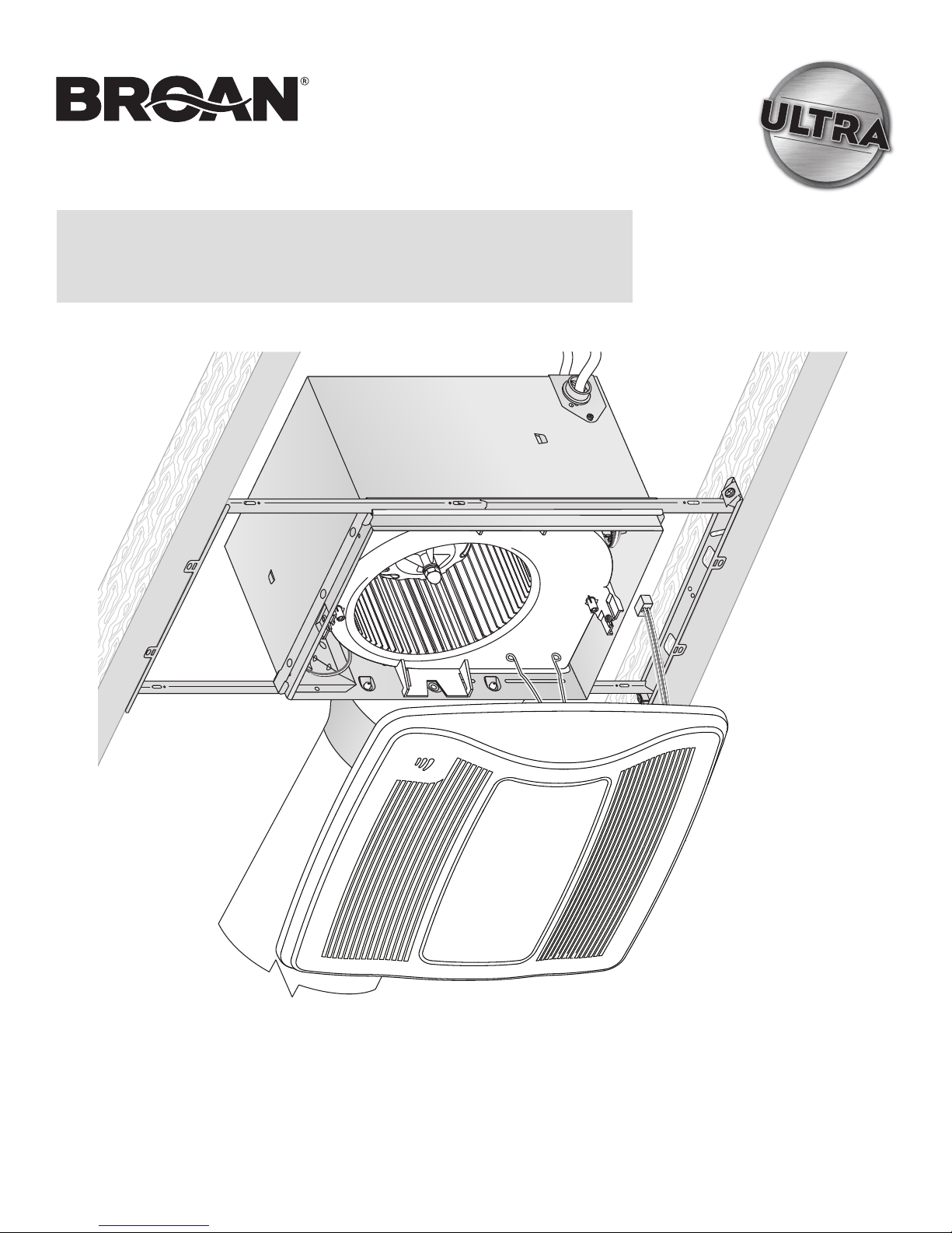
ZB110HL
X2 | Multi-Speed Ventilation
Fan with Light, Night Light
and Humidity Sensor
INSTALLATION GUIDE
Easy installation in both
new construction and retrofit
© 2017 Broan
Table of Contents
W
arnings and Cautions
Typical Installation
New Construction Installation
Retrofit Installation
Operation
Cleaning and Maintenance
Troubleshooting
Service Parts
2
2
3
7
12
12
12
13
Page 2
Page 2
ZB110HL Installation Guide
WARNING
TO REDUCE THE RISK OF FIRE, ELECTRIC SHOCK, OR
INJURY TO PERSONS, OBSERVE THE FOLLOWING:
1. Use this unit only in the manner intended by the manufacturer.
If you have questions, contact the manufacturer at the address
or telephone number listed in the warranty.
2. Before servicing or cleaning unit, switch power off at service
panel and lock the service disconnecting means to prevent
power from being switched on accidentally. When the service
disconnecting means cannot be locked, securely fasten a
prominent warning device, such as a tag, to the service panel.
3. Installation work and electrical wiring must be done by a
qualified person(s) in accordance with all applicable codes
and standards, including fire-rated construction codes and
standards.
4. Sufficient air is needed for proper combustion and exhausting
of gases through the flue (chimney) of fuel burning equipment
to prevent backdrafting. Follow the heating equipment
manufacturer’s guideline and safety standards such as those
published by the National Fire Protection Association (NFPA),
and the American Society for Heating, Refrigeration and
Air Conditioning Engineers (ASHRAE), and the local code
authorities.
5. When cutting or drilling into wall or ceiling, do not damage
electrical wiring and other hidden utilities.
6. Ducted fans must always be vented to the outdoors.
7. Use only ON/OFF switch, mechanical timer or relay-switched
control.
8. Acceptable for use over a tub or shower when connected to
a GFCI (Ground Fault Circuit Interrupter) - protected branch
circuit.
9. This unit must be grounded.
CAUTION
1. For general ventilating use only. Do not use to exhaust
hazardous or explosive materials and vapors.
2. This product is designed for installation in flat ceilings. Sensor
will not function reliably if product is not installed in flat ceiling.
DO NOT MOUNT THIS PRODUCT IN A WALL.
3. To avoid motor bearing damage and noisy and/or unbalanced
impellers, keep drywall spray, construction dust, etc. off power
unit.
4. Please read specification label on product for further
information and requirements.
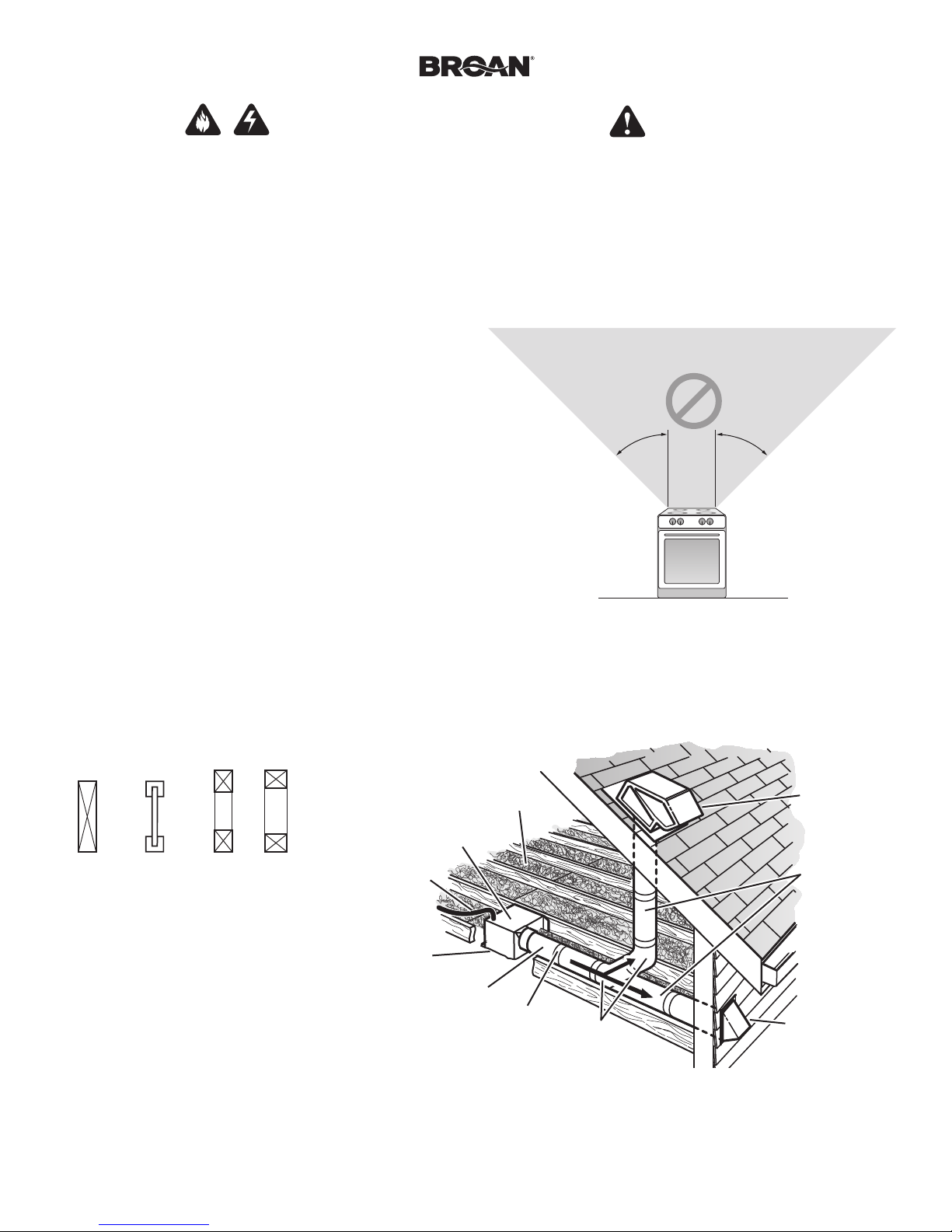
NOT FOR USE IN A COOKING AREA
Do not install above or inside this area
45° 45°
Cooking
Equipment
Floor
Typical Installation
• Installation is the same for:
Joists I-Joists Trusses
• Fits in 2" x 8" ceiling construction.
• Infinitely adjust the fan position
between joists from 14" to 24"
on center.
The ducting from this fan to the outside of the building has a strong effect on the air flow, noise and energy use of the fan. Use the shortest, straighest duct routing possible for best performance, and avoid
installing the fan with smaller ducts than recommended. Insulation around the ducts can reduce energy loss and inhibit mold growth. Fans installed with existing ducts may not achieve their rated airflow.
HOUSING
POWER
CABLE*
Seal gaps
around
Housing.
*Purchase
separately.
INSULATION*
(Place around and
over Fan Housing.)
FAN
ROUND
DUCT*
Seal duct
joints with
tape.
OR
ROUND
ELBOWS*
ROOF CAP*
(with built-in
damper)
Keep duct
runs short.
WALL CAP*
(with built-in
damper)
6-inch round rigid metal duct is recommended for best performance.
Page 3
Page 3
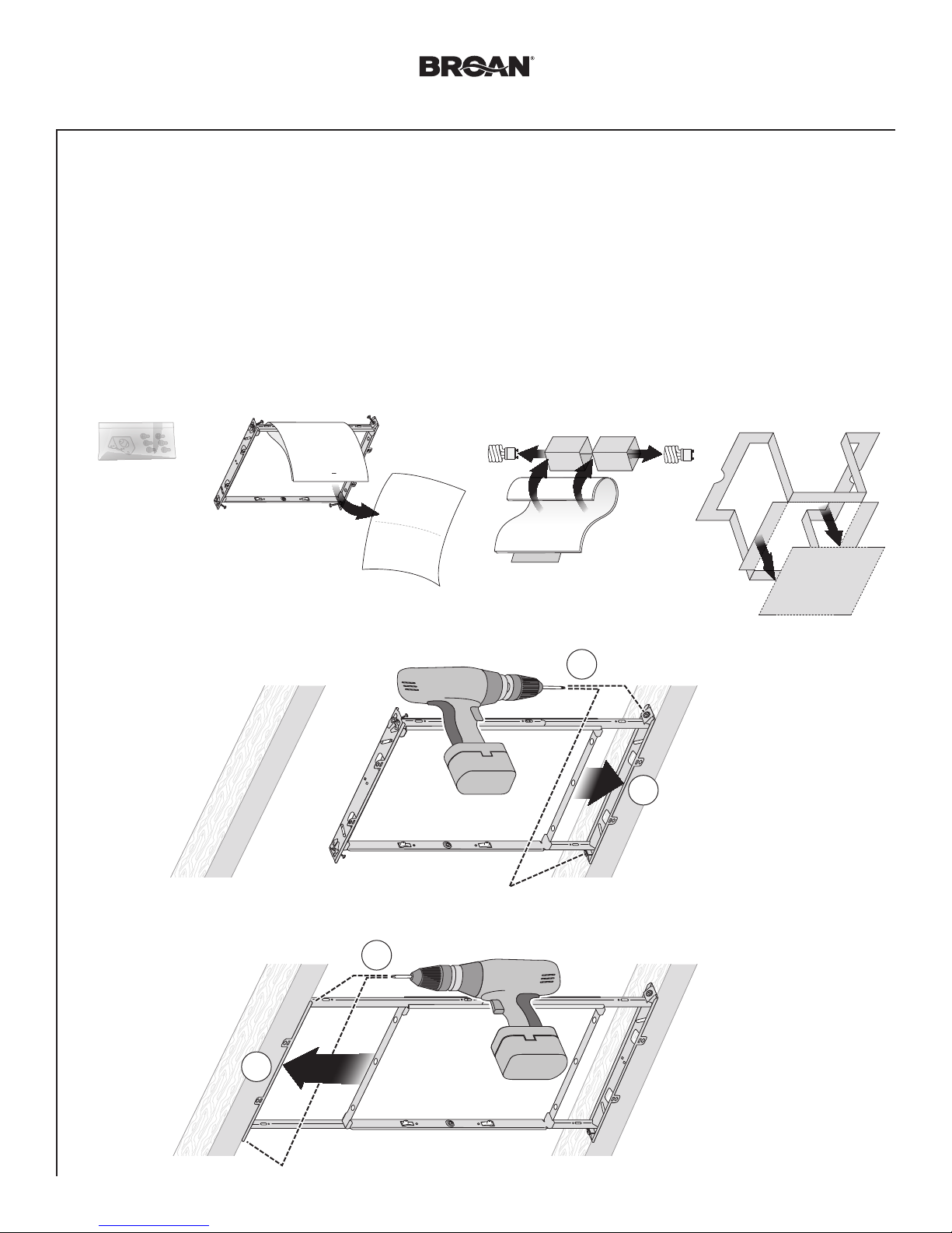
New Construction Installation
ZB110HL Installation Guide
Tools needed
• Power screwdriver with a Phillips bit
• Phillips screwdriver
• Flathead screwdriver
• Pliers
• Wire insulation stripper
• Wire cutter
Remove Packaging
1
Parts Bag holds
Knockout Plate
and six (6)
screws
Materials needed
• 6" round metal ducting recommended for best performance.
Use of other ducting is acceptable but may impact performance.
• Roof cap or wall cap (built-in damper recommended)
• Tape to seal duct connections
• Electrical wiring and supplies per local code requirements
• 4W (max.) C7-type night light bulb
Remove CFL Bulbs
from protective packaging
Remove
Instruction
Sheet
Punch out Mask from
packaging. See Step 6.
Install
2
Mounting
Frame
2
1
4
3
Page 4
Page 4
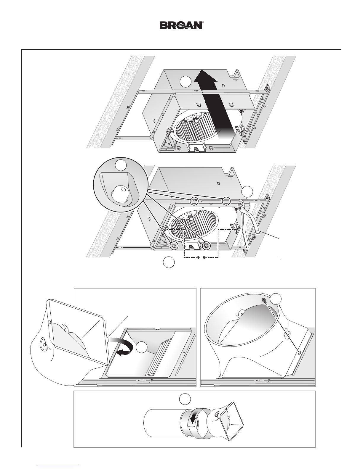
New Construction Installation
Snap-in and
3
Secure Housing
2
snap!
ZB110HL Installation Guide
1
4
4
Screws from Parts Bag
3
Attach Duct Connector and Ducting
Top and bottom flanges
go outside Housing
Insert tab into slot
inside Housing
1
Position Housing
between joists and
crimp channel on both
sides of Mounting Frame
to lock Housing in place.
Do not crimp Housing.
Screw from
2
Parts Bag
6" Ducting
3
Tape
Page 5

Page 5
New Construction Installation
Connect Wires and Install Knockout Plate
5
• Run 120VAC electrical wiring to the installation location.
• Use proper UL-approved connectors to secure wiring to the Knockout Plate provided in Parts Bag.
• Connect wires as shown in wiring diagram.
• Do not use a dimmer switch to operate the light.
Attach cable clamps to Knockout
1
Plate. Knockout Plate mounts to
outside of Housing and may be
oriented as desired.
ZB110HL Installation Guide
3
Fan
WHT
120 VAC
LINE IN
SENSOR / CONTROL
BLK
GRD
SENSOR/CONTROL
BLACK
WHITE
ORANGE
MANUAL - ON
MASTER
(purchase separately)
Light
2
MULTI-FUNCTION
WALL SWITCHES
MANUAL-ON
MASTER
RED
BLUE
BROWN
MULTI-FUNCTION
WALL CONTROLS
Connect wires
LIGHT
NIGHT
LIGHT
SWITCH
BOX
LIGHT
NIGHT
LIGHT
WHT
BLK
RED
RED
BLU
BLK
WHT
GRD
GROUND
(green or bare)
120 VAC
LINE IN
KNOCKOUT
14/3
14/4
(IF ALL
WALL SWITCH
OPTIONS
ARE USED)
LIGHT RECEPTACLE WIRES
PLATE
ORG
RECEPTACLES
FAN RECEPTACLE
WIRES
RED
BRN
BLU
RED
BLK
4
Screw from
Parts Bag
• See OPERATION
section on page 12 for
details.
• MASTER switch
WHT
LIGHT
NIGHT
LIGHT
SENSOR/
CONTROL
BLK
FAN
WHT
• MANUAL-ON switch is not required
to manually increase fan operation to
certified airflow rate (see page 10).
• MASTER and SENSOR/CONTROL
switches can be combined (see page
10).
• MASTER switch along with or
separate from SENSOR/CONTROL
switch may be located where they
are not easily accessed for everyday
usage, they may need to be labeled
and located where they can’t be
turned on without being seen from
fan to comply with local and national
codes.
turns fan system on
and shuts it off for
fan cleaning and
maintenance purposes.
• SENSOR/CONTROL
switch turns humidity
control automatic
operation on/off.
• MANUAL-ON switch
directly increases fan
operation to certified
airflow rate.
• MASTER switch must
be on for humidity
control or MANUAL-ON
switch to change fan
operation to certified
airflow rate.
Page 6

Page 6
New Construction Installation
Insert Mask and
6
Finish Ceiling
• Install ceiling material.
• Cut out around Housing.
CAUTION
IN ORDER TO PREVENT
MOTOR/CONTROL DAMAGE:
If the blower was unplugged, power must be
disconnected (see page 2, WARNING item 2)
before inserting motor plugs into control assembly.
Install Grille
7
ZB110HL Installation Guide
Mask protects unit
during construction.
Remove before
installing Grille.
Plug in
Sensor
Install Bulbs
8
1
Plug in
2
Light
3
4
3
2
1
Night Light
(purchase
separately)
4
See Page 12 for Operations, Cleaning
and Maintenance, and Troubleshooting.
Page 7

Page 7
Retrofit Installation
ZB110HL Installation Guide
Tools needed
• Power screwdriver with a Phillips bit
• Phillips screwdriver
• Flathead screwdriver
• Pliers
• Wire insulation stripper
• Wire cutter
• Ruler
• Pencil
• Drywall saw
• Claw hammer or pry bar
• Utility knife
Materials needed
• Tape to seal duct connections
• Existing rigid duct will require the
addition of a short length of flexible duct
• Electrical wiring and supplies per
local code requirements
• 4W (max.) C7-type night light bulb
Remove Packaging
1
Remove
Instruction
Sheet
Parts Bag holds
Knockout Plate
and six (6)
screws
Remove CFL Bulbs
from protective packaging
Switch Off Power
2
WARNING
Before removing existing fan, switch power off at service panel and lock the service disconnecting
means to prevent power from being switched on accidentally. When the service disconnecting means
cannot be locked, securely fasten a prominent warning device, such as a tag, to the service panel.
Punch out Mask from
packaging. See Step 12.
Enlarge Ceiling Opening and Remove Existing Fan
3
12" (30.5 cm)
1
11" (27.9 cm)
parallel with joists
Existing ductwork and
wiring left in place
Examine Wiring
4
Examine the existing wiring to make sure it is not damaged. If any damage is found,
DO NOT CONTINUE INSTALLATION of this product. Contact a qualified person(s) for repair.
2
Page 8

Page 8
Retrofit Installation
Remove Blower Assembly
5
ZB110HL Installation Guide
6
2
Both sides
Remove Wiring Panel
Set aside
screw
1
2
1
Set aside
Blower
Assembly
3
Set aside
Wiring Panel
3
Insert
7
Mounting
Frame
4
3
1
Remove screws from
Mounting Frame
and set aside
5
2
Bend up
four tabs
Page 9

Page 9
Retrofit Installation
Secure
8
Mounting
Frame
Snap-in Housing
9
ZB110HL Installation Guide
Screws set
aside
in Step 7
2
10
Pull existing
ductwork
into Housing
1
Pull existing wiring into
Housing as it is inserted
into Mounting Frame
snap!
Attach Ducting and Duct Connector
1
2
4
Screw from
Parts Bag
3
Insert tab into
slot inside
Housing
6" Ducting
Tape
Page 10

Page 10
Retrofit Installation
Install Knockout Plate, Connect Wires and Reinstall Wiring Panel
11
• Use proper UL-approved connectors to secure wiring to the Knockout Plate provided in Parts Bag.
• Connect wires as shown in wiring diagram.
• Do not use a dimmer switch to operate the light.
1
mounts to inside of
2
Screw from
Parts Bag
Attach cable
clamps to
Knockout Plate.
Knockout Plate
Housing and may
be oriented
as desired.
ZB110HL Installation Guide
Screw set
aside in
Step 6
5
6
4
Connect wires
3
Fan
Light
• See OPERATION section on page
12 for details.
• MASTER switch turns fan system on
along with humidity control and shuts
them off for cleaning and maintenance
purposes.
• Toggle mode can be used to manually
increase fan operating airflow to certified
rate.
• MASTER switch may be located where
it is not easily accessed for everyday
usage; it may need to be labeled and
located where it can’t be turned on
without being seen from fan to comply
with local and national codes.
GRD
WHT
120 VAC
LINE IN
BLK
BLACK
WHITE
ORANGE
MASTER
STANDARD OR
MULTI-FUNCTION
WALL CONTROLS
(purchase separately)
MULTI-FUNCTION
MASTER
LIGHT
STANDARD OR
WALL SWITCHES
NIGHT
LIGHT
LIGHT
NIGHT
LIGHT
RED
BLUE
BROWN
SWITCH
BOX
120 VAC
LINE IN
GRD
WHT
BLK
RED
14/3
14/2
BLK
WHT
GROUND
(green or bare)
LIGHT RECEPTACLE WIRES
KNOCKOUT
PLATE
WHT
BLU
LIGHT
RED
NIGHT
LIGHT
BLK
FAN
RED
BLK
BRN
SENSOR/
CONTROL
ORG
WHT
RECEPTACLES
FAN RECEPTACLE
WIRES
Page 11

Pa g e 11
1
2 3
Retrofit Installation
Reinsert and Secure Blower Assembly
12
CAUTION
Power must be disconnected (see page 2, WARNING item 2) before inserting motor plugs into control assembly.
ZB110HL Installation Guide
IN ORDER TO PREVENT MOTOR/CONTROL DAMAGE:
13
14
Install Grille
Plug in
Sensor
1
Install Bulbs
1
If ceiling repairs are needed, place Mask in Housing after Blower
3
Assembly is secured. See New Construction Installation Step 6.
Plug in
2
Light
2 3
Remove Mask before installing Grille.
4
Screws from Parts Bag
2
1
3
Night Light
(purchase
separately)
4
Page 12

Page 12
ZB110HL Installation Guide
WARNING Before servicing or cleaning unit,
switch power off at service panel and lock the service
disconnecting means to prevent power from being switched on
accidentally. When the service disconnecting means cannot be
locked, securely fasten a prominent warning device, such as a
tag, to the service panel.
Operation
It is normal for this ventilation fan to take approximately 5 seconds to start running after it is turned on.
Modes
(For reference, wiring diagrams are on pages 5 and 10.)
Continuous ventilation:
1. Turn master wall switch on (make sure any other wall
switches are off).
2. Fan operates at user-adjustable airflow rate.
Humidity sensing:
1. If master wall switch is not already on, turn it on.
2. Turn sensor/control wall switch on (make sure any other wall
switches are off). Some installations may not have a separate
sensor/control wall switch; where it is combined with master
wall switch.
3. Sensor monitors humidity level for (a) moderate to rapid rise
or (b) above set-point.
4. Fan operates at certified airflow rate to reduce humidity.
5. When humidity decreases, fan enters time delay mode. (See
below.)
Manual-on (optional manual-on wall switch must be installed):
1. Turn master and manual-on wall switches on (sensor/control
wall switch can be on or off).
2. Fan operates at certified airflow rate.
3. When manual-on wall switch is turned off, fan enters timedoff mode. (See below.)
Toggle (for manual operation when optional manual-on wall
switch is not installed):
1. If master wall switch is not already on, turn it on.
2. Turn sensor/control wall switch on (make sure any other wall
switches are off). Some installations may not have a separate
sensor/control wall switch; where it is combined with master
wall switch then turn master wall switch on and off using
following instructions.
3. Wait at least one-second.
4. Turn switch off for less than one-second.
5. Turn switch back on.
6. Fan will operate at certified airflow rate and enter time delay
mode. (See next.)
Time Delay:
Fan operates at certified airflow rate until user-adjustable TIME
delay has passed, then fan reverts to user-adjustable airflow rate.
To Set the User-Adjustable Airow Rate*
Using a small, flat-blade screwdriver, carefully rotate the CFM
adjustment until the arrow points to the desired airflow rate.
To Set the User-Adjustable Time Delay*
Using a small, flat-blade screwdriver, carefully rotate the TIME
adjustment until arrow points to the desired minutes of time
delay.
* The user-adjustable controls are located in one corner of the
Fan Housing, behind the Grille.
To Turn Fan OFF
Turn the master switch OFF.
Cleaning and Maintenance
CAUTION
IN ORDER TO PREVENT MOTOR/CONTROL DAMAGE:
DO NOT remove motor plug to stop spinning motor.
Power must be disconnected (see WARNING at top left of this page)
before motor plug is removed or inserted into control assembly.
To Clean
For quiet and efficient operation,
long life and attractive appearance,
remove Grille and vacuum interior
of unit with a dusting brush
attachment.
Do not use cleaning sprays,
solvents or water on, or near, the
sensor.
Motor is permanently lubricated
and never needs oiling. If motor is making excessive or unusual
noises, replace Control Assembly and Motor.
To Change Bulbs
Refer to Retrofit Installation Step 14 (page 11).
1. Carefully insert a small flathead screwdriver between the Grille
and Lens, then twist to remove Lens.
2. Purchase two (2) 18W (max.) type GU24 fluorescent lamps
with Maximum Overall Length (MOL) of 3.9” (100 mm).
Purchase a 4W (max.) C7-type incandescent night light bulb.
3. Insert bulbs into their sockets. Replace Lens.
M.O.L.
3.9" (100 mm)
To Set User-Adjustable
Humidity Sensitivity**
Using a small, flat-blade
screwdriver, carefully rotate
HUMIDITY adjustment until
arrow points to desired
humidity level shown in
percent relative humidity (%RH).
** User-adjustable humidity sensitivity is located in corner of
Fan Housing behind Grille.
Page 13

Page 13
ZB110HL Installation Guide
Troubleshooting
Before continuing, turn off power as previously noted in WARNING
and CAUTION sections on the previous page.
Symptom: Fan does not run.
• Check for an open fuse or circuit breaker in building’s service
panel.
• Check two (2) plug-in connections for Motor and its Control are
seated firmly in place.
• Check two (2) plug-in connections for Sensor and its Control
are seated firmly in place.
• Check that Blower Wheel spins freely.
Symptom: Humidity mode does not operate fan at certied air
ow rate.
• Check two (2) plug-in connections for Sensor and its Control
are seated firmly in place.
Symptom: Fan runs erratically.
• Check that Blower Wheel is firmly attached to Motor shaft and
both spin freely.
Symptom: Fan seems noisy.
• Check that back draft damper in fan’s Duct Connector pivots
freely. Screws used to attach duct to Duct Connector may
prevent damper from opening.
• Check that back draft damper in wall or roof cap pivots freely.
Dampers are sometimes mistakenly painted shut or obstructed
by bird or insect debris.
Symptom: Fan does not properly ventilate room.
• For spot ventilation, turn both master switch and sensor/control
wall switch ON, so sensor/control operates fan at certified
airflow rate.
• For spot ventilation followed by continuous ventilation, increase
the “TIME” setting of user-adjustable time delay.
• For continuous ventilation, increase “CFM” setting of useradjustable airflow rate.
Service Parts
7
Order replacement
parts by Part No.,
not by Key No.
1
2
3
4
6
8
9
11
5
Key No. Part No. Description
1 97018349 Mounting Frame
2 97018721 Knockout Plate & Screws
3 97018382 Housing
4 97018474 Wiring Panel/Harness Assembly
5 97019012 Humidity Control Assembly & Grille Assembly
(includes Key Nos. 10, 11)
6 97020845 Control Assembly & Motor
7 97018331 Duct Connector - 6"
8 99020301 Blower Wheel
9 97018768 Scroll Assembly
10 99140208 Grille Spring (2 req’d)
11 99111542 Lens
12 99271381 Bulb, GU24 18W 3500K Fluorescent (2 req’d)
10
12
Looking for RV hardware? Visit our website.
 Loading...