

Page 1
READ AND SAVE THESE INSTRUCTIONS
Installer: leave this guide with homeowner.
Register your product online at www.broan.ca/register.asp
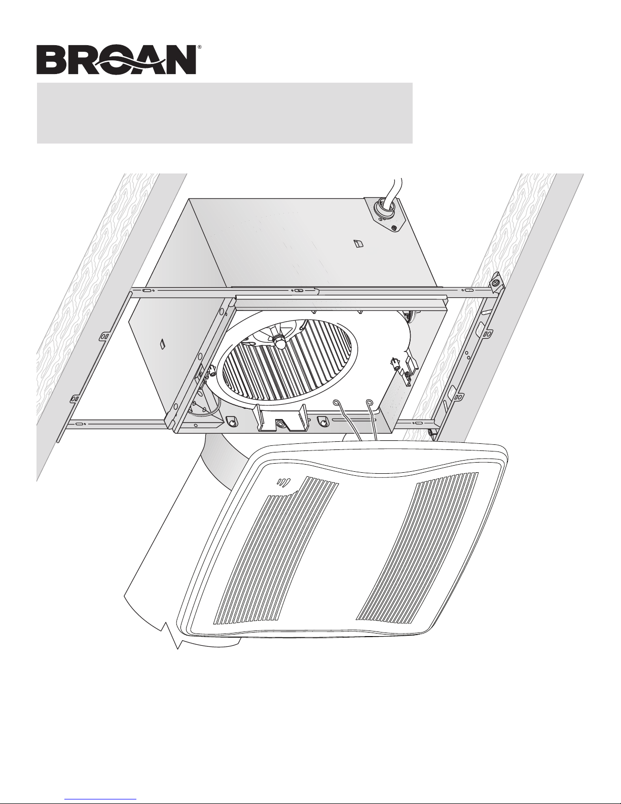
XB90HC n XB110HC
X1 | Single-Speed
Ventilation Fan
with Humidity Sensor
INSTALLATION GUIDE
Easy installation in both
new construction and retrofit
© 2012 Broan-NuTone LLC
Table of Contents
Warnings and Cautions 2
Typical Installation 2
New Construction Installation 3
Retrofit Installation 7
Operation 12
Cleaning and Maintenance 12
Troubleshooting 12
Service Parts 13
Warranty 13
Page 2
Page 2
!
XB90HC n XB110HC Installation Guide
WARNING
TO REDUCE THE RISK OF FIRE, ELECTRIC SHOCK, OR
INJURY TO PERSONS, OBSERVE THE FOLLOWING:
1. Use this unit only in the manner intended by the manufacturer.
If you have questions, contact the manufacturer at the address
or telephone number listed in the warranty.
2. Before servicing or cleaning unit, switch power off at service
panel and lock the service disconnecting means to prevent
power from being switched on accidentally. When the service
disconnecting means cannot be locked, securely fasten a
prominent warning device, such as a tag, to the service panel.
3. Installation work and electrical wiring must be done by a
qualified person(s) in accordance with all applicable codes
and standards, including fire-rated construction codes and
standards.
4. Sufficient air is needed for proper combustion and exhausting
of gases through the flue (chimney) of fuel burning equipment
to prevent backdrafting. Follow the heating equipment
manufacturer’s guideline and safety standards such as those
published by the National Fire Protection Association (NFPA),
and the American Society for Heating, Refrigeration and
Air Conditioning Engineers (ASHRAE), and the local code
authorities.
5. When cutting or drilling into wall or ceiling, do not damage
electrical wiring and other hidden utilities.
6. Ducted fans must always be vented to the outdoors.
7. Use only ON/OFF switch, mechanical timer or relay-switched
control.
8. Acceptable for use over a tub or shower when connected to
a GFCI (Ground Fault Circuit Interrupter) - protected branch
circuit.
9. This unit must be grounded.
CAUTION
1. For general ventilating use only. Do not use to exhaust
hazardous or explosive materials and vapors.
2. This product is designed for installation in flat ceilings. Sensor
will not function reliably if product is not installed in flat ceiling.
DO NOT MOUNT THIS PRODUCT IN A WALL.
3. To avoid motor bearing damage and noisy and/or unbalanced
impellers, keep drywall spray, construction dust, etc. off power
unit.
4. Please read specification label on product for further
information and requirements.
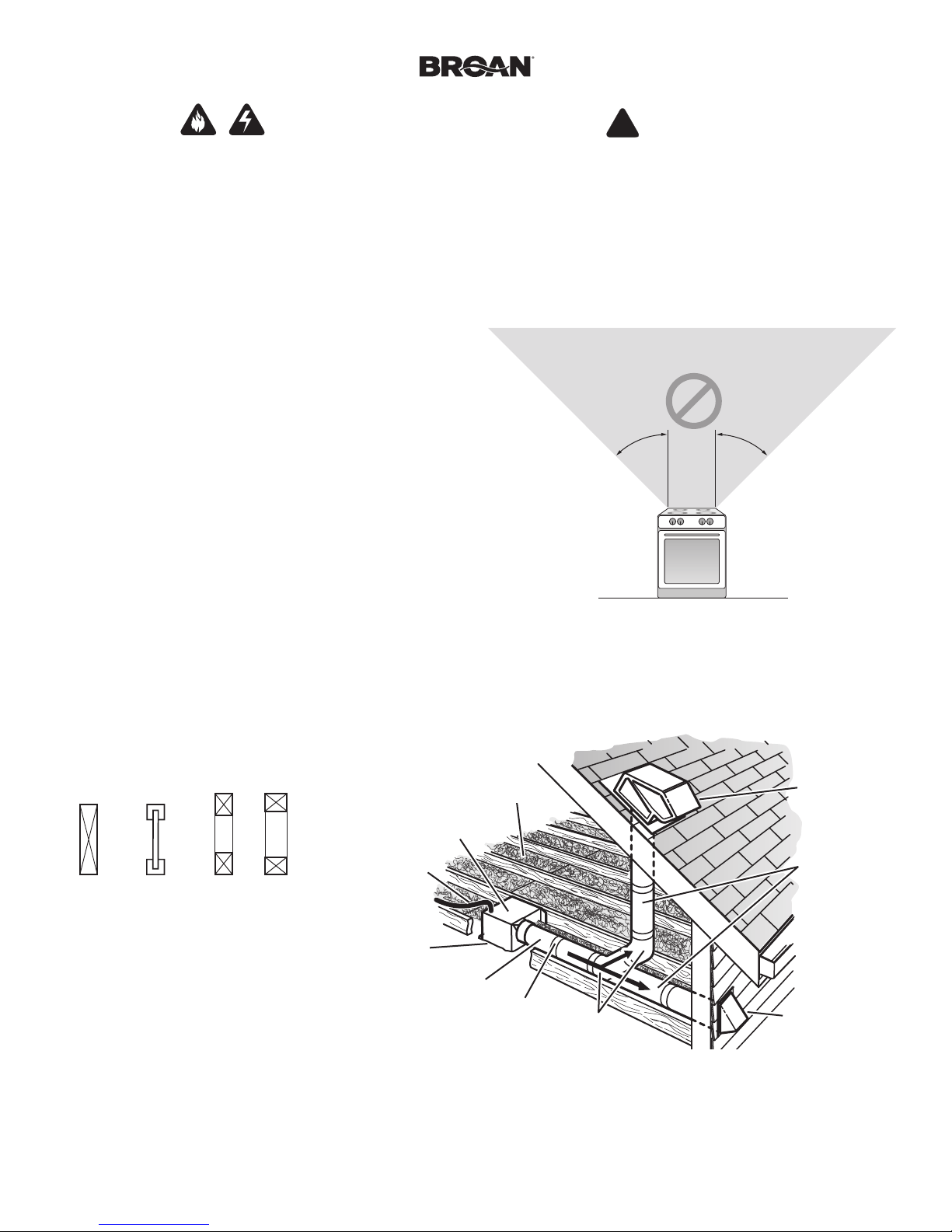
NOT FOR USE IN A COOKING AREA
Do not install above or inside this area
45° 45°
Cooking
Equipment
Floor
Typical Installation
• Installation is the same for:
Joists I-Joists Trusses
• Fits in 2" x 8" ceiling construction.
• Infinitely adjust the fan position
between joists from 14" to 24"
on center.
The ducting from this fan to the outside of the building has a strong effect on the air flow, noise and energy use of the fan. Use the shortest, straighest duct routing possible for best performance, and avoid
installing the fan with smaller ducts than recommended. Insulation around the ducts can reduce energy loss and inhibit mold growth. Fans installed with existing ducts may not achieve their rated airflow.
6-inch round rigid metal duct is recommended for best performance.
HOUSING
POWER
CABLE*
Seal gaps
around
Housing.
*Purchase
separately.
INSULATION*
(Place around and
over Fan Housing.)
FAN
ROUND
DUCT*
Seal duct
joints with
tape.
OR
ROUND
ELBOWS*
ROOF CAP*
(with built-in
damper)
Keep duct
runs short.
WALL CAP*
(with built-in
damper)
Page 3
Page 3
New Construction Installation
XB90HC n XB110HC Installation Guide
Tools needed
• Power screwdriver with a Phillips bit
• Phillips screwdriver
• Flathead screwdriver
• Pliers
• Wire insulation stripper
• Wire cutter
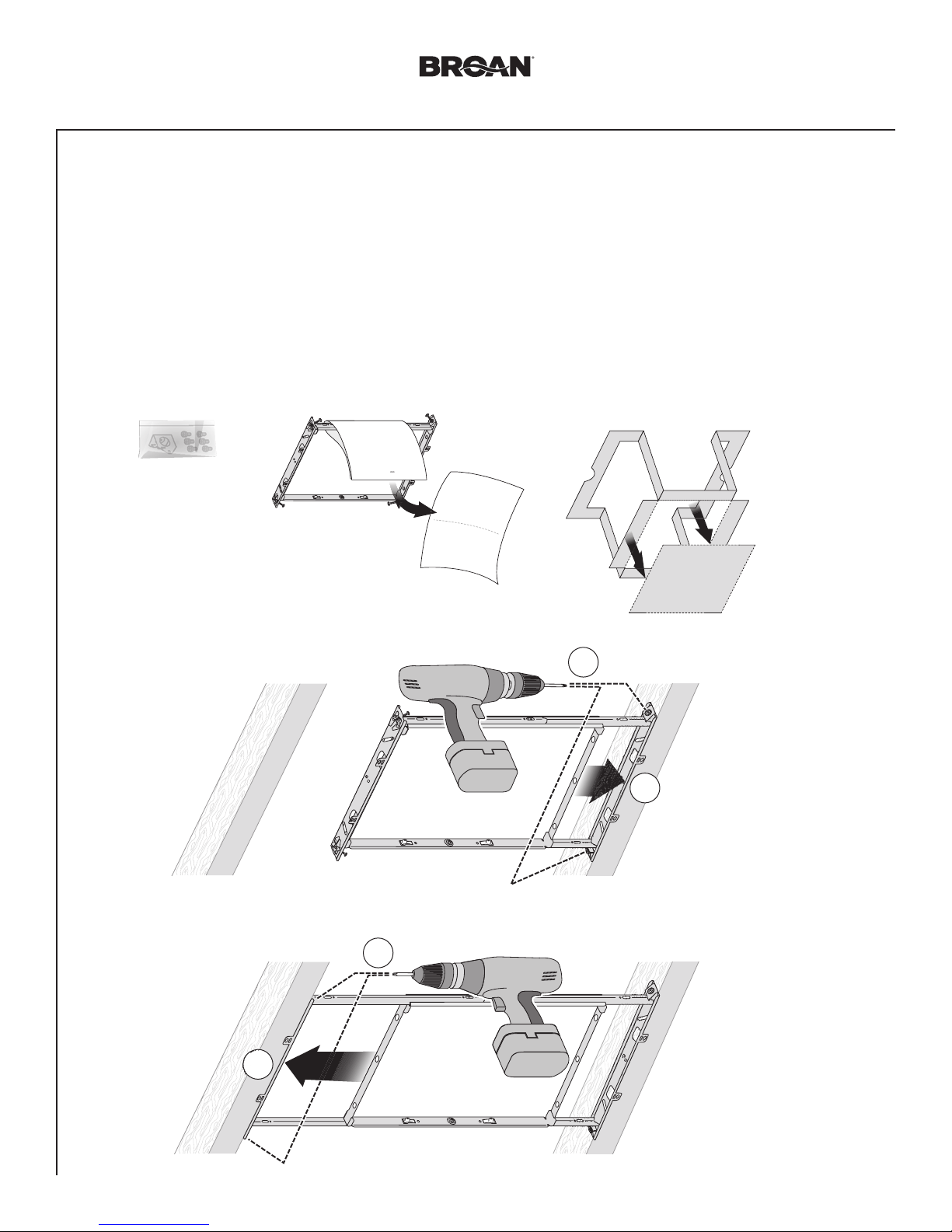
Remove Packaging
1
Parts Bag holds
Knockout Plate
and six (6)
screws
Materials needed
• 6" round metal ducting recommended for best performance.
Use of other ducting is acceptable but may impact performance.
• Roof cap or wall cap (built-in damper recommended)
• Tape to seal duct connections
• Electrical wiring and supplies per local code requirements
Punch out Mask from
packaging. See Step 6.
Remove
Instruction
Sheet
Install
2
2
Mounting
Frame
1
4
3
Page 4
Page 4
New Construction Installation
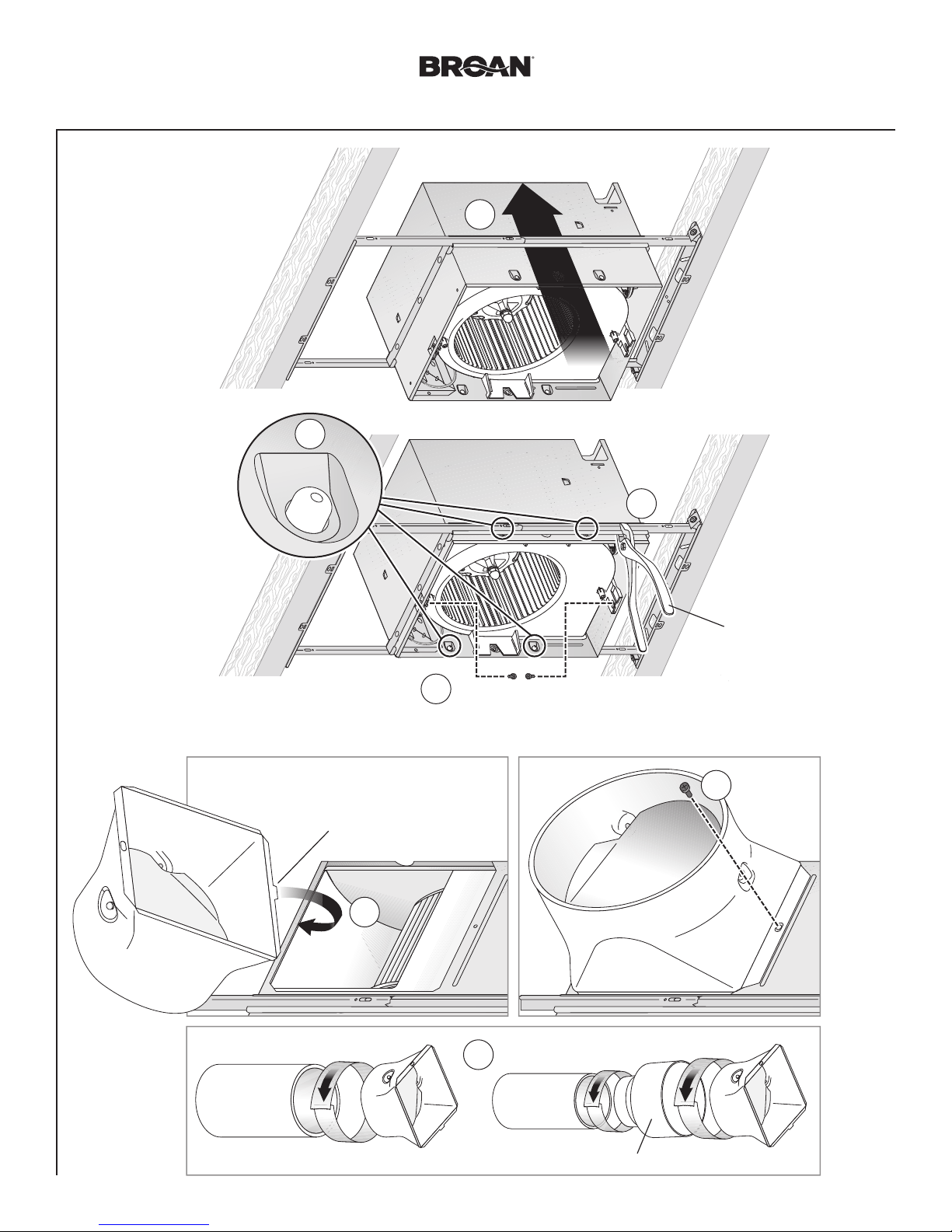
Snap-in and
3
Secure Housing
2
snap!
XB90HC n XB110HC Installation Guide
1
4
Attach Duct Connector and Ducting
4
Top and bottom flanges
go outside Housing
Insert tab into slot
inside Housing
1
6" Ducting
Tape
Screws from Parts Bag
3
3
4" Ducting
Tape
Position Housing
between joists and
crimp channel on both
sides of Mounting Frame
to lock Housing in place.
Do not crimp Housing.
Screw from
2
Parts Bag
Tape
6" to 4" Reducer provided in select models
Page 5
Page 5
LINE IN
BLACK
RED
ORANGE
New Construction Installation
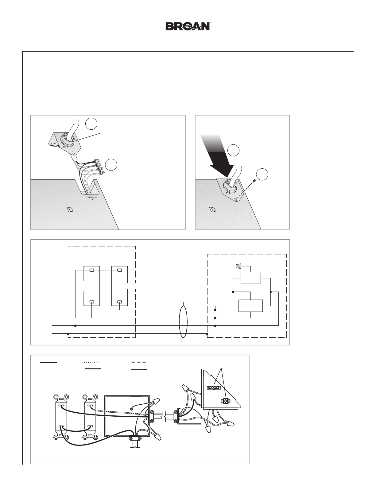
Connect Wires and Install Knockout Plate
5
• Run 120VAC electrical wiring to the installation location.
• Use proper UL-approved connectors to secure wiring to the Knockout Plate provided in Parts Bag.
• Connect wires as shown in wiring diagram.
Attach cable clamp to Knockout
1
Plate. Knockout Plate mounts to
outside of Housing and may be
oriented as desired.
Connect wires
2
XB90HC n XB110HC Installation Guide
3
4
Screw from
Parts Bag
STANDARD OR MULTI-
FUNCTION WALL SWITCHES
SENSOR/
CONTROL
BLK
20 VAC
WHT
GND
WHITE
MANUAL
ON
SWITCH*
SENSOR
CONTROL
SWITCH*
purchase separately
*
MANUAL-ON
BROWN
SWITCH BOX
120 VAC
LINE IN
14/3
(IF ALL
WALL SWITCH
OPTIONS
ARE USED)
RED
BLK
WHT
GND
GROUND
(green or bare)
KNOCKOUT
PLATE
BLK
ORG
BRN
RECEPTACLES
RED
FAN
BLK
SENSOR/
CONTROL
WHT
• See OPERATION section on page 12
for details.
• SENSOR/CONTROL switch turns
humidity control on for automatic
operation and off for fan cleaning and
maintenance purposes.
• MANUAL-ON switch directly turns fan
on/off.
• MANUAL-ON switch not required to
manually turn fan on (see page 10).
• SENSOR/CONTROL switch may be
located where it is not easily accessed
for everyday usage; it may need to
be labeled and located where it can’t
be turned on without being seen from
fan to comply with local and national
codes.
Page 6
Page 6
New Construction Installation
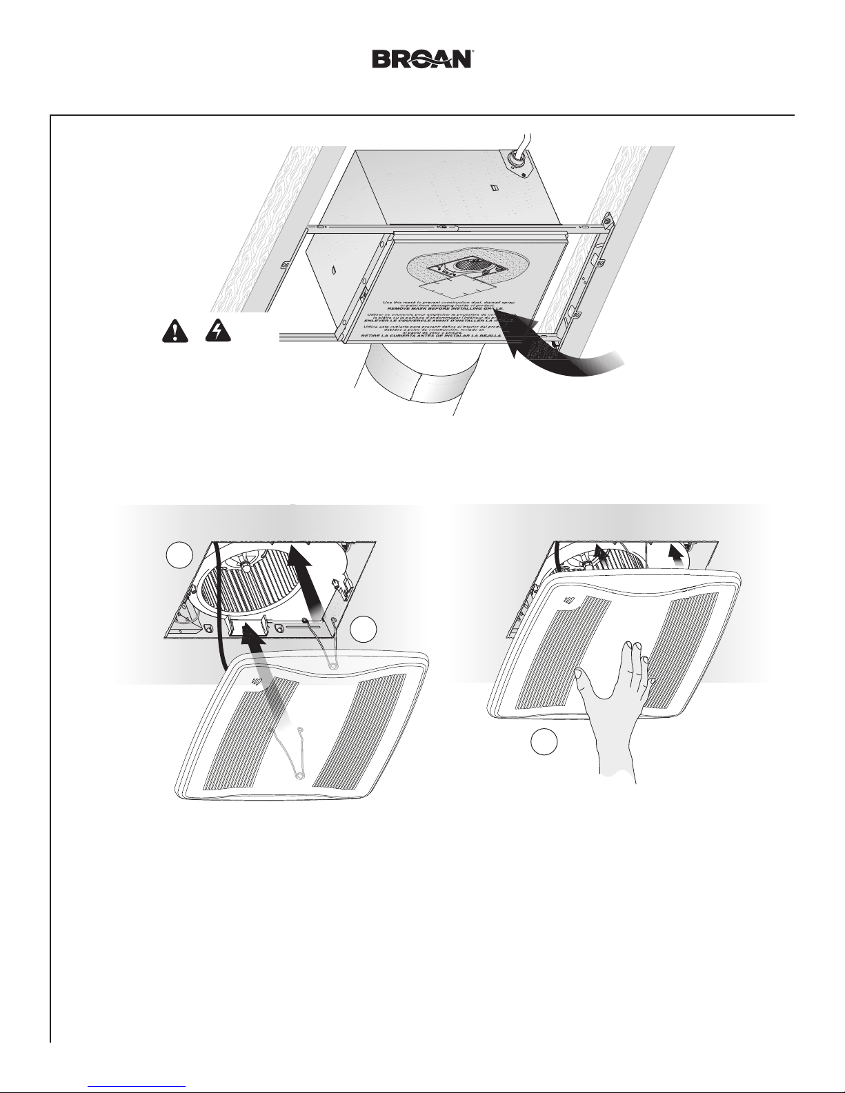
Insert Mask and
6
Finish Ceiling
• Install ceiling material.
• Cut out around Housing.
CAUTION
IN ORDER TO PREVENT MOTOR/CONTROL DAMAGE:
If the blower was unplugged, power must be
disconnected (see page 2, WARNING item 2)
before inserting motor plug into control assembly.
XB90HC n XB110HC Installation Guide
Mask protects unit
during construction.
Remove before
installing Grille.
Install Grille
7
Plug in
Sensor
See Page 12 for Operations, Cleaning and Maintenance, and Troubleshooting.
1
2
3
Page 7
Page 7
Retrofit Installation
XB90HC n XB110HC Installation Guide
Tools needed
• Power screwdriver with a Phillips bit
• Phillips screwdriver
• Flathead screwdriver
• Pliers
• Wire insulation stripper
• Wire cutter
• Ruler
• Pencil
• Drywall saw
• Claw hammer or pry bar
• Utility knife
Materials needed
• Tape to seal duct connections
• Existing rigid duct will require the
addition of a short length of flexible duct
• Electrical wiring and supplies per
local code requirements
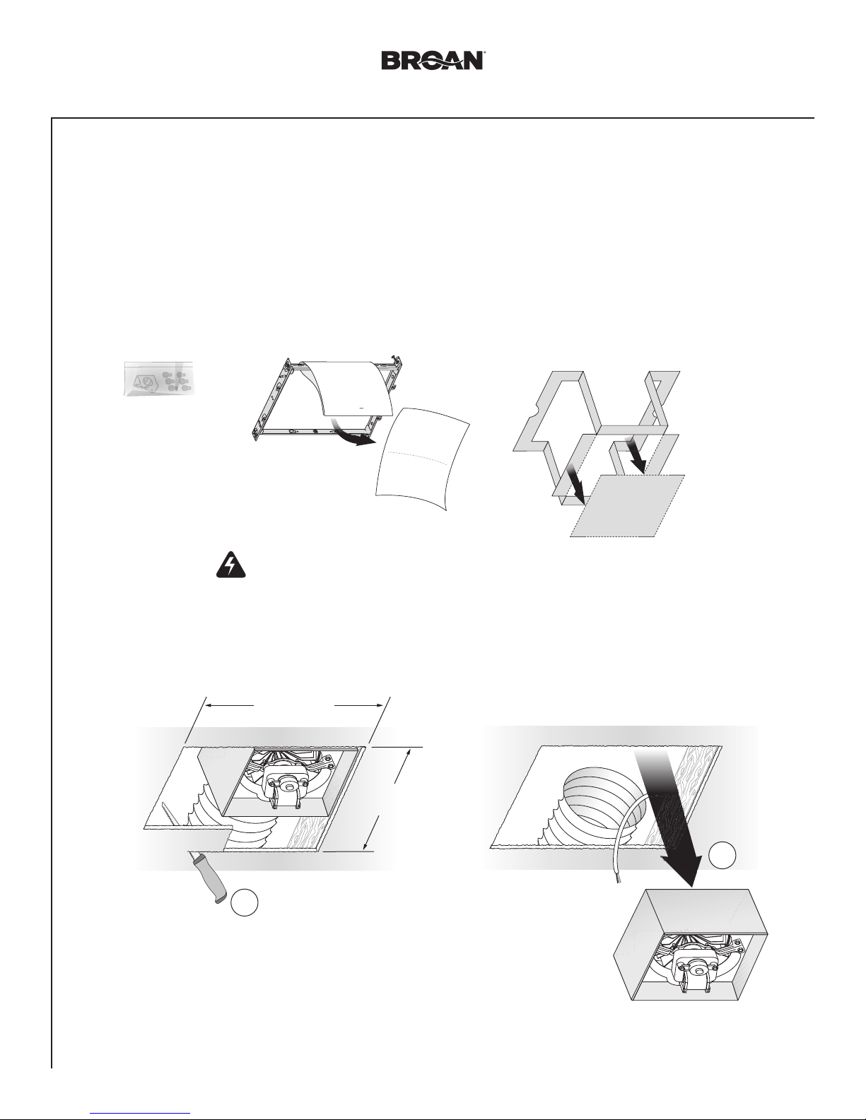
Remove Packaging
1
Parts Bag holds
Knockout Plate
and six (6)
screws
Remove
Instruction
Sheet
Punch out Mask from
packaging. See Step 12.
Switch Off Power
2
WARNING
Before removing existing fan, switch power off at service panel and lock the service disconnecting
means to prevent power from being switched on accidentally. When the service disconnecting means
cannot be locked, securely fasten a prominent warning device, such as a tag, to the service panel.
Enlarge Ceiling Opening and Remove Existing Fan
3
12" (30.5 cm)
1
11" (27.9 cm)
parallel with joists
Existing ductwork and
wiring left in place
Examine Wiring
4
Examine the existing wiring to make sure it is not damaged. If any damage is found,
DO NOT CONTINUE INSTALLATION of this product. Contact a qualified person(s) for repair.
2
Page 8
Page 8
Retrofit Installation
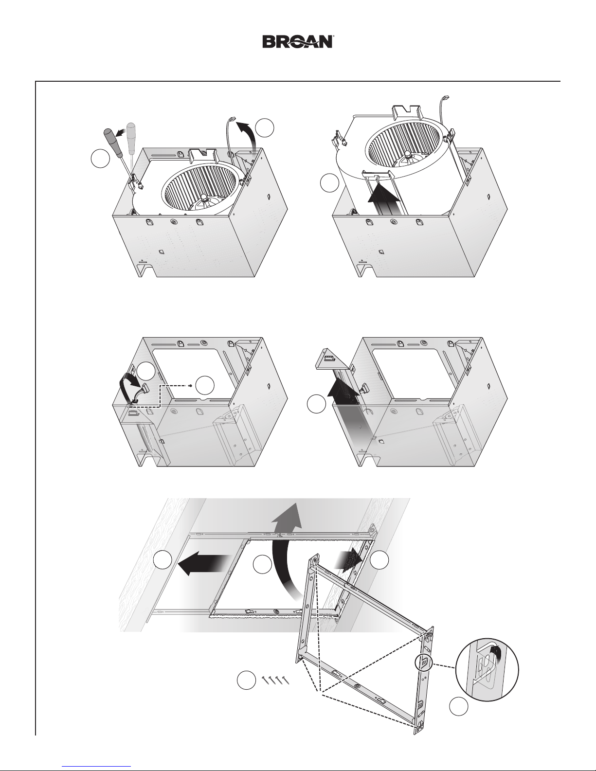
Remove Blower Assembly
5
2
Both sides
Remove Wiring Panel
6
XB90HC n XB110HC Installation Guide
1
3
Set aside
Wiring Panel
Set aside
Blower Assembly
Insert
7
Mounting
Frame
1
Set aside
screw
4
2
3
3
5
1
Remove screws from
Mounting Frame
and set aside
2
Bend up
four tabs
Page 9
Page 9
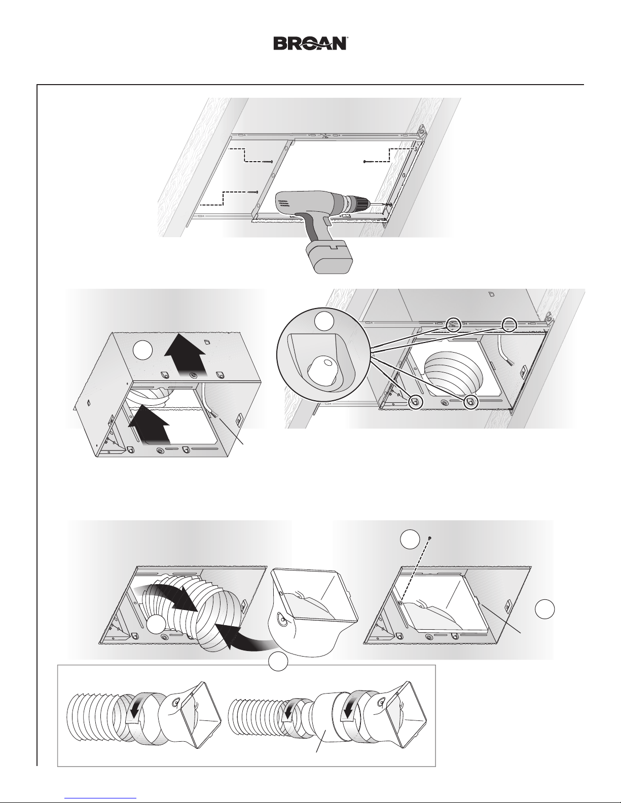
Retrofit Installation
Secure
8
Mounting
Frame
Snap-in Housing
9
XB90HC n XB110HC Installation Guide
Screws set
aside
in Step 7
2
10
Pull existing
ductwork
into Housing
1
Pull existing wiring into
Housing as it is inserted
into Mounting Frame
snap!
Attach Ducting and Duct Connector
1
4
Screw from
Parts Bag
3
Insert tab into
slot inside
Housing
6" Ducting
Tape
2
4" Ducting
6" to 4" Reducer provided in select models
Tape
Tape
Page 10

Page 10
1
LINE IN
ORANGERED
Retrofit Installation
Install Knockout Plate, Connect Wires and Install Wiring Panel
11
Screw from
Parts Bag
• Use proper UL-approved connectors to secure wiring to the Knockout Plate provided in Parts Bag.
• Connect wires as shown in wiring diagram.
Attach cable clamp to Knockout
1
Plate. Knockout Plate mounts to
inside of Housing and may be
oriented as
2
XB90HC n XB110HC Installation Guide
desired.
Screw set
aside in
Step 6
5
6
4
Connect
3
wires
• See OPERATION section on page
12 for details.
• SENSOR/CONTROL switch allows
humidity control to be turned on for
automatic operation and off for fan
cleaning and maintenance purposes.
• Toggle mode can be used to manually
turn fan on.
• SENSOR/CONTROL switch may be
located where it is not easily accessed
for everyday usage; it may need to be
labeled and located where it can’t be
turned on without being seen from
fan to comply with local and national
codes.
BLK
20 VAC
LINE IN
WHT
GND
BLACK
WHITE
CONTROL*
purchase separately
*
SENSOR/
CONTROL
SENSOR
BLK
WHT
GND
BROWN
SWITCH BOX
120 VAC
14/2
GROUND
(green or bare)
BLK
ORG
BRN
KNOCKOUT
PLATE
RED
FAN
BLK
SENSOR/
CONTROL
WHT
RECEPTACLES
Page 11

Pa g e 11
Retrofit Installation
Insert and Secure Blower Assembly
12
CAUTION
Power must be disconnected (see page 2, WARNING item 2) before inserting motor plug into control assembly.
XB90HC n XB110HC Installation Guide
IN ORDER TO PREVENT MOTOR/CONTROL DAMAGE:
13
Plug in
Sensor
Install Grille
1
1
2
2 3
If ceiling repairs are needed, place Mask in
Housing after Blower Assembly is secured.
See New Construction Installation Step 6.
Remove Mask before installing Grille.
3
Screws from Parts Bag
Page 12

Page 12
WARNING Before servicing or cleaning unit,
switch power off at service panel and lock the service
disconnecting means to prevent power from being switched
on accidentally. When the service disconnecting means
cannot be locked, securely fasten a prominent warning
device, such as a tag, to the service panel.
Operation
Modes
(For reference, wiring diagrams are on pages 5 and 10.)
Humidity sensing:
1. Turn sensor/control wall switch on (make sure manual-on wall
switch is off if it is installed).
2. Sensor monitors humidity level for (a) moderate to rapid rise
or (b) above set-point.
3. Fan operates at certified airflow rate to reduce humidity.
4. When humidity decreases, fan enters time delay mode. (See
below.)
Manual-on (optional manual-on wall switch must be installed):
1. Turn manual-on wall switch on (sensor/control wall switch can
be on or off).
2. Fan operates at certified airflow rate.
3. Fan turns off when manual-on wall switch is turned off. (See
below.)
Toggle (for manual operation when optional manual-on wall
switch is not installed or manually activated timed-off is
desired):
1. Turn sensor/control wall switch on (make sure manual-on wall
switch is off if it is installed).
2. Wait at least one-second.
3. Turn switch off for less than one-second.
4. Turn switch back on.
5. Fan will operate at certified airflow rate and enter time delay
mode. (See next.)
Time Delay:
Fan continues to run until user-adjustable TIME delay has
passed, then fan turns off.
To Set User-Adjustable Humidity Sensitivity**
Using a small, flat-blade screwdriver, carefully rotate HUMIDITY
adjustment until arrow points to desired humidity level shown in
percent relative humidity (%RH).
To Set User-Adjustable Time Delay**
Using a small, flat-blade screwdriver, carefully rotate TIME
adjustment until the arrow points to the desired minutes of time
delay.
** User-adjustable controls are located in corner of Fan Housing
behind Grille.
XB90HC n XB110HC Installation Guide
Cleaning and Maintenance
CAUTION
IN ORDER TO PREVENT MOTOR/CONTROL DAMAGE:
DO NOT remove motor plug to stop spinning motor.
Power must be disconnected (see WARNING at top left of
this page) before motor plug is removed or inserted into
control assembly.
To Clean
For quiet and efficient operation, long life and attractive
appearance, remove Grille and vacuum interior of unit with a
dusting brush attachment.
Do not use cleaning sprays, solvents or water on, or near, the
sensor.
Motor is permanently lubricated and never needs oiling. If
motor is making excessive or unusual noises, replace Control
Assembly and Motor.
Troubleshooting
Before continuing, turn off power as previously noted in
WARNING and CAUTION sections at the top of this page.
Symptom: Fan does not run.
• Check for an open fuse or circuit breaker in the building’s service panel.
• Check that the two (2) plug-in connections for the Motor and the Control are seated firmly in place.
• Check two (2) plug-in connections for Sensor and its
Control are seated firmly in place.
• Check that the Blower Wheel spins freely.
Symptom: Humidity mode does not operate fan.
• Check two (2) plug-in connections for Sensor and its
Control are seated firmly in place.
Symptom: The fan runs erratically.
• Check that the Blower Wheel is firmly attached to the
Motor shaft and both spin freely.
Symptom: The fan seems noisy.
• Check that the back draft damper in the fan’s Duct
Connector pivots freely. Screws used to attach the duct
to the Duct Connector may be preventing the damper
from opening.
• Check that the back draft damper in the wall or roof cap
pivots freely. These dampers are sometimes mistakenly
painted shut or obstructed by bird and insect debris.
Page 13

Page 13
XB90HC n XB110HC Installation Guide
Service Parts
1
2
3
4
7
8
Order replacement
parts by Part No.,
not by Key No.
5
Key No. Part No. Description
1 97018349 Mounting Frame
2 97018721 Knockout Plate & Screws
3 97018382 Housing
4 97018887 Wiring Panel/Harness Assembly
5 97019009 Humidity Control Assembly & Grille Assembly
(includes Key No. 11)
6 97019397 Control Assembly & Motor (XB90HC)
97018759 Control Assembly & Motor (XB110HC)
7 97018331 Duct Connector
8 99111513 6” to 4” Reducer (Model XB90HC only)
9 99020301 Blower Wheel
10 97019371 Scroll Assembly (XB90HC)
97018768 Scroll Assembly (XB110HC)
11 99140208 Grille Spring (2 req’d)
6
9
10
11
Warranty
Broan Ventilation Fans Limited Warranty
WARRANTY PERIOD: Broan warrants to the original consumer purchaser of
its Broan Ventilation Fans (the “Fan”) that your Fan will be materially free from
defects in materials or workmanship for a period of three (3) years from the date
of original purchase. This warranty does not cover accessories, such as speed
controls, that may be purchased separately and installed with the Fan.
The limited warranty period for replacement parts, and for Fans repaired or
replaced under this limited warranty, shall continue for the remainder of the
original warranty period.
NO OTHER WARRANTIES: THE FOREGOING WARRANTIES ARE
EXCLUSIVE AND IN LIEU OF ANY OTHER WARRANTIES, EXPRESS OR
IMPLIED. BROAN DISCLAIMS AND EXCLUDES ALL OTHER EXPRESS
WARRANTIES, AND DISCLAIMS AND EXCLUDES ALL WARRANTIES
IMPLIED BY LAW, INCLUDING WITHOUT LIMITATION THOSE OF
MERCHANTABILITY AND FITNESS FOR A PARTICULAR PURPOSE. TO THE
EXTENT THAT APPLICABLE LAW PROHIBITS THE EXCLUSION OF IMPLIED
WARRANTIES, THE DURATION OF ANY APPLICABLE IMPLIED WARRANTY
IS LIMITED TO THE PERIOD SPECIFIED FOR THE EXPRESS WARRANTY.
Some states do not allow limitations on how long an implied warranty lasts, so the
above limitation may not apply to you. Any oral or written description of the Fan
is for the sole purpose of identifying it and shall not be construed as an express
warranty.
REMEDY: During the applicable limited warranty period, Broan will, at its
option, provide replacement parts for, or repair or replace, without charge,
any Fan or part thereof, to the extent Broan finds it to be covered by and in
breach of this limited warranty. Broan will ship the repaired or replaced Fan
or replacement parts to you at no charge. You are responsible for all costs
for removal, reinstallation and shipping, insurance or other freight charges
incurred in the shipment of the Fan or part to Broan. This warranty does not
cover (a) normal maintenance and service, (b) normal wear and tear, (c) any
Fans or parts which have been subject to misuse, abuse, abnormal usage,
negligence, accident, improper or insufficient maintenance, storage or repair
(other than repair by Broan), (d) damage caused by faulty installation, or
installation or use contrary to recommendations or instructions, (e) any Fan
that has been moved from its original point of installation, (f) damage caused
by environmental or natural elements, (g) damage in transit, (h) natural wear
of finish, (i) Fans in commercial or nonresidential use, or (j) damage caused by
fire, flood or other act of God. This warranty covers only Fans sold in Canada
or through Canadian distributors authorized by Broan.
EXCLUSION OF DAMAGES: BROAN’S OBLIGATION TO PROVIDE
REPLACEMENT PARTS, OR REPAIR OR REPLACE, AT BROAN’S OPTION,
SHALL BE YOUR SOLE AND EXCLUSIVE REMEDY UNDER THIS LIMITED
WARRANTY AND BROAN’S SOLE AND EXCLUSIVE OBLIGATION. BROAN
SHALL NOT BE LIABLE FOR INCIDENTAL, INDIRECT, CONSEQUENTIAL OR
SPECIAL DAMAGES ARISING OUT OF OR IN CONNECTION WITH THE FAN,
ITS USE OR PERFORMANCE. Incidental damages include but are not limited to
such damages as loss of time and loss of use. Consequential damages include
but are not limited to the cost of repairing or replacing other property which was
damaged if the Fan does not work properly.
Some states do not allow the exclusion or limitation of incidental or consequential
damages, so the above limitation or exclusion may not apply to you. This warranty
gives you specific legal rights, and you may also have other rights, which vary
from state to state.
This warranty supersedes all prior warranties and is not transferable from the
original consumer purchaser.
BROAN SHALL NOT BE LIABLE TO YOU, OR TO ANYONE CLAIMING UNDER
YOU, FOR ANY OTHER OBLIGATIONS OR LIABILITIES, INCLUDING, BUT
NOT LIMITED TO, OBLIGATIONS OR LIABILITIES ARISING OUT OF BREACH
OF CONTRACT OR WARRANTY, NEGLIGENCE OR OTHER TORT OR ANY
THEORY OF STRICT LIABILITY, WITH RESPECT TO THE FAN OR BROAN’S
ACTS OR OMISSIONS OR OTHERWISE.
This warranty covers only replacement or repair of defective Fans or parts thereof
at Broan’s main facility and does not include the cost of field service travel and
living expenses.
Any assistance Broan provides to or procures for you outside the terms, limitations
or exclusions of this limited warranty will not constitute a waiver of such terms,
limitations or exclusions, nor will such assistance extend or revive the warranty.
Broan will not reimburse you for any expenses incurred by you in repairing or
replacing any defective Fan, except for those incurred with Broan’s prior written
permission.
HOW TO OBTAIN WARRANTY SERVICE: To qualify for warranty service, you
must (a) notify Broan at the address or telephone number stated below within
seven (7) days of discovering the covered defect, (b) give the model number and
part identification and (c) describe the nature of any defect in the Fan or part. At
the time of requesting warranty service, you must present evidence of the original
purchase date.
Broan-NuTone Canada Inc., 1140 Tristar Drive, Mississauga, Ontario, L5T 1H9
(1-877-896-1119)
www.broan.ca
If you must send the Fan or part to Broan, as instructed by Broan, you must
properly pack the Fan or part—Broan is not responsible for damage in transit.
Page 14

Page 14
XB90HC n XB110HC Installation Guide
99045105C
Page 15

LISEZ ET CONSERVEZ CES INSTRUCTIONS
À l’attention de l’installateur: laissez ce guide chez le client.
Enregistrez votre produit en ligne sur www.broan.ca/register.asp
XB90HC n XB110HC
X1 | Ventilateur monovitesse
avec détecteur d’humidité
GUIDE D’INSTALLATION
Installation facile,
lors de construction
neuve ou de rénovations
© 2012 Broan-NuTone LLC
Table des matières
Avertissementset mises en garde 16
Installation type 16
Installation dans une construction neuve 17
Installation lors de rénovation 21
Fonctionnement 26
Nettoyage et entretien 26
Dépannage 26
Pièces de rechange 27
Garantie 27
Page 16

Page 16
!
XB90HC n XB110HC Guide d’installation
AVERTISSEMENT
POUR DIMINUER LE RISQUE D’INCENDIE, D’ÉLECTROCUTION OU
DE BLESSURE, RESPECTER LES PRÉCAUTIONS CI-DESSOUS:
1. N’utilisez cet appareil que de la manière prévue par son fabricant.
Si vous avez des questions, communiquez avec le fabriquant à
l’adresse ou au numéro de téléphone indiqués dans la garantie.
2. Avant toute intervention sur l’appareil ou nettoyage de celui-ci,
couper l’alimentation électrique au tableau de distribution et
verrouiller le dispositif de sectionnement pour empêcher toute
remise sous tension accidentelle. S’il est impossible de verrouiller
le dispositif de sectionnement, y fixer solidement et de manière
visible un dispositif d’affichage (par ex. : une étiquette).
3. Les travaux d’installation et de raccordement électrique doivent
obligatoirement être effectués par du personnel qualifié,
conformément aux codes et normes applicables, y compris les
codes et normes relatifs aux constructions résistantes au feu.
4. Une quantité suffisante d’air est nécessaire pour assurer la
bonne combustion et l’évacuation par la cheminée des gaz
produits par les appareils brûlant du combustible, pour éviter tout
refoulement. Respecter les recommandations du fabriquant de
l’appareil et les normes de sécurité comme celles publiées par la
National Fire Protection Association (NFPA), l’American Society
for Heating, Refrigeration and Air Conditioning Engineers et les
autorités locales responsables des codes.
5. Lorsque vous coupez un mur ou un plafond, prenez garde de ne
pas endommager les fils électriques ou autres installations qui
pourraient y être dissimulés.
6. Les ventilateurs avec conduit doivent toujours évacuer l’air
à l’extérieur.
7. N’utilisez qu’un interrupteur MARCHE/ARRÊT, une minuterie
mécanique ou une commande à relais.
8. Cet appareil convient à une installation au-dessus de la baignoire
ou de la douche lorsqu’il est relié à un circuit protégé par un
disjoncteur de fuite à la terre (DDFT).
9. Cet appareil doit obligatoirement être mis à la terre.
ATTENTION
1. Réservé exclusivement à la ventilation générale. Ne pas utiliser
pour évacuer des matières ou des vapeurs dangereuses
ou explosives.
2. Ce produit est conçu pour être installé dans des plafonds plats.
Le détecteur ne pourra fonctionner de façon fiable si ce produit est
installé dans un plafond en pente. NE PAS MONTER CE PRODUIT
DANS UN MUR.
3. Pour éviter d’endommager les paliers du moteur et les roues de
devenir bruyantes et (ou) mal équilibrées, garder votre appareil
à l’abri des poussières de gypse, de construction, etc
4. Consulter l’étiquette des caractéristiques sur le produit pour
plus de renseignements ou exigences.
NE PAS UTILISER DANS UNE CUISINE
Ne pas installer au-dessus ou à l’intérieur de cette zone
45° 45°
Appareil
de cuisson
Plancher
.
Instalation type
• L’installation est identique pour:
Solive Poutrelle Fermes
en « I » de toit
• Convient à un plafond construit
en 2 po x 8 po.
• Le ventilateur s’installe n’importe où entre
les solives, de 14 po à 24 po d’entraxe.
Les conduits allant de ce ventilateur jusqu’à l’extérieur de l’habitation ont une grande influence sur le débit d’air, le bruit
du ventilateur et sa consommation d’énergie. Pour obtenir le meilleur rendement, utilisez les conduits les plus courts
et les plus droits que possible et évitez d’utiliser des conduits plus petits que ceux recommandés. L’isolation des conduits peut contribuer à réduire les pertes d’énergie et éviter la prolifération de moisissures. Les ventilateurs installés sur
d’anciens conduits pourraient ne pas produire leur débit d’air nominal.
Pour un rendement optimal, il est recommandé d’utiliser des conduits métalliques ronds de 15.2 cm (6 po) de diamètre.
ISOLATION*
(Répartir autour
et au-dessus du boîtier
du ventilateur.)
BOÎTIER DE
VENTILATEUR
CORDON
D’ALIMENTATION*
Calfeutrer
les espaces
autour du ventilateur.
CONDUIT ROND*
* Vendu séparément.
Sceller les joints
de conduit avec
du ruban adhésif.
OU
COUDES
RONDS*
CAPUCHON
DE TOIT*
(avec
clapet intégré)
Garder le
tracé des
conduits court.
CAPUCHON
MURAL*
(avec clapet intégré)
Page 17

Page 17
Installation dans une construction neuve
XB90HC n XB110HC Guide d’installation
Outils nécessaires
• Tournevis électrique avec embout Phillips
• Tournevis Phillips
• Tournevis à lame plate
• Pinces
• Pince à dénuder
• Pince coupante
Retirer l’emballage
1
Le sachet de
pièces contient
une plaque de
câblage et
six (6) vis.
Matériaux nécessaires
•
Conduit rond en métal de 6 po recommandé pour une meilleure performance.
Du conduit différent est acceptable, au prix d’une performance inférieure.
• Capuchon de toit ou de mur (recommandé avec clapet intégré).
• Ruban adhésif pour l’étanchéité des joints.
• Câblage et fournitures électriques en fonction des exigences du code local.
Découper le masque dans
l’emballage. Voir l’étape 6.
Enlever la feuille
d’instructions.
Installer le cadre
2
de montage
2
1
4
3
Page 18

Page 18
Installation dans une construction neuve
Encliqueter et
3
fixer le boîtier
1
2
Encliqueté!
XB90HC n XB110HC Guide d’installation
4
Vis du sachet de pièces
3
Fixer le raccord de conduit et le conduit
4
Les rebords supérieur et inférieur
vont à l’extérieur du boîtier.
Introduire la languette
dans la fente à l’intérieur
du boîtier.
1
Conduit
de 6po
Ruban
adhésif
Mettre le boîtier en place
entre les solives et
pincer la glissière de
chaque côté du cadre de
montage pour verrouiller
le boîtier en place.
Ne pas pincer le boîtier.
Vis du
2
sachet
de pièces
Conduit
3
de 4po
Ruban
adhésif
Ruban
adhésif
Réducteur de 6 po à 4 po fourni avec certains modèles
Page 19

Page 19
NOIR
ROUGE
ORANGE
Installation dans une construction neuve
Raccorder les fils et installer la plaque de câblage
5
• Acheminer les fils 120V CA à l’emplacement de l’installation.
• Raccorder les fils à la plaque de câblage fournie dans le sachet de pièces à l’aide de connecteurs homologués UL.
• Raccorder les fils tel qu’il est indiqué au schéma de câblage.
Fixer le collier à la plaque de
1
câblage. La plaque de câblage
s’installe à l’extérieur du boîtier,
d’un côté comme de l’autre.
Raccorder les fils.
2
XB90HC n XB110HC Guide d’installation
3
4
Vis du
sachet
de pièces
LIGNE
D’ENTRÉE
DE 120 VCA
NOIR
BLANC
Mise à
la terre
INTERRUPTEUR
DE COMMANDE
DU CAPTEUR*
* Acheter séparément
INTERRUPTEURS STANDARDS
OU MULTIFONCTION
INTERRUPTEUR
DU CAPTEUR
BLANC
INTERRUPTEUR
MANUEL*
INTERRUPTEUR
MANUEL
BRUN
BOÎTIER
D’INTERRUPTEURS
LIGNE D’ENTRÉE
DE 120 VCA
14/3
(SI TOUTES LES
OPTIONS
D’INTERRUPTEUR
SONT UTILISÉES)
ROUGE
NOIR
BLANC
Mise à la terre
Mise à la terre
(VERT ou dénudé)
PLAQUE
DE CÂBLAGE
NOIR
ORANGE
BRUN
RÉCEPTACLES
• Voir la section
FONCTIONNEMENT
à la page 26 pour tous
ROUGE
les détails.
• L’interrupteur
VENTILATEUR
NOIR
CAPTEUR/
COMMANDE
active le contrôle
d’humidité pour
CONTRÔLE
DU CAPTEUR
le fonctionnement
automatique et le
met sur Arrêt pour le
BLANC
nettoyage et l’entretien
du ventilateur.
• L’interrupteur
MANUEL-MARCHE
actionne ou arrête
directement le
ventilateur.
• L’interrupteur MANUEL-MARCHE
n’est pas nécessaire pour mettre le
ventilateur en marche manuellement
(voir page 24).
• L’interrupteur CAPTEUR/
COMMANDE peut être placé à un
endroit où il ne sera pas facilement
accessible pour l’utilisation quotidienne;
il se peut qu’il doive être étiqueté
et il devra être situé à un endroit
permettant de voir le ventilateur pour
être conforme aux codes locaux et
nationaux.
Page 20

Page 20
Installation dans une construction neuve
Mettre le masque
6
et finir le plafond
• Installer le matériau
du plafond.
• Découper autour
du boîtier.
ATTENTION
POUR ÉVITER D’ENDOMMAGER
LE MOTEUR/LA COMMANDE :
Si le ventilateur a été débranché, l’alimentation doit être
coupée avant d’insérer la fiche du moteur dans l’ensemble
de commande (voir page 16, AVERTISSEMENT point 2).
XB90HC n XB110HC Guide d’installation
Le masque protège l’appareil
pendant les travaux . Retirer
le masque avant d’installer
la grille.
Installer la grille
7
Brancher
le capteur
Voir page 26 pour le fonctionnement, le nettoyage et l’entretien ainsi que pour le dépannage.
1
2
3
Page 21

Page 21
1
2
Installation lors de rénovation
XB90HC n XB110HC Guide d’installation
Outils nécessaires
• Tournevis électrique avec embout Phillips
• Tournevis Phillips
• Tournevis à lame plate
• Pinces
• Pince à dénuder
• Pince coupante
• Règle
• Crayon
• Scie à cloison sèche
• Marteau à panne fendue ou levier
• Couteau universel
Matériaux nécessaires
• Ruban adhésif pour l’étanchéité des joints
• Un conduit rigide existant nécessite l’ajout
d’une courte section de conduit flexible
• Câblage et fournitures électriques en
fonction des exigences du code local
Retirer l’emballage
1
Le sachet de
pièces contient
une plaque de
câblage et
six (6) vis.
Enlever la feuille
d’instructions.
Découper le masque dans
l’emballage. Voir l’étape 12.
Couper l’alimentation
2
AVERTISSEMENT
Avant de retirer le ventilateur existant, couper l’alimentation électrique au tableau de distribution et verrouiller le
dispositif de sectionnement pour empêcher toute remise sous tension accidentelle. S’il est impossible de verrouiller le
dispositif de sectionnement, y fixer solidement et de manière visible un dispositif d’affichage (par ex. : une étiquette).
Agrandir l’ouverture dans le plafond et retirer le ventilateur existant
3
Examiner les fils
4
Vérifier les fils existants pour s’assurer qu’ils soient en bon état. S’ils sont endommagés,
NE PAS CONTINUER L’INSTALLATION de ce produit. Prendre contact avec un technicien qualifié pour la réparation.
12 po (30,5 cm)
11 po (27,9 cm)
parallèle aux solives
Conduit et câblage
existants restant en place
Page 22

Page 22
Installation lors de rénovation
Retirer l’ensemble ventilateur
5
2
Des deux côtés
Retirer le panneau de branchement
6
1
3
Mettre de côté le panneau
de branchement
XB90HC n XB110HC Guide d’installation
Mettre de côté
l’ensemble ventilateur.
Installer le
7
cadre
de montage
Mettre de côté
la vis
1
4
2
3
3
5
1
Retirer et
conserver les
vis du cadre de montage.
2
Replier
les quatre
languettes.
Page 23

Page 23
Installation lors de rénovation
Fixer le cadre
8
de montage
Encliqueter le boîtier
9
XB90HC n XB110HC Guide d’installation
Vis conservées
lors de l’étape 7
2
10
Introduire le
conduit existant
dans le boîtier.
Conduit
de 6po
1
Faire passer les fils existants dans
le boîtier en insérant celui-ci
dans le cadre de montage.
Encliqueté!
Fixer le raccord de conduit et le conduit
1
2
Ruban
adhésif
Conduit
de 4po
Ruban
adhésif
Ruban
adhésif
4
Vis du sachet
de pièces
3
Introduire la
languette
dans la fente
à l’intérieur
du boîtier.
Réducteur de 6 po à 4 po fourni avec certains modèles
Page 24

Page 24
DE 120 VCA
LIGNE
D’ENTRÉE
DE 120 VCA
Installation lors de rénovation
Installer la plaque de câblage, raccorder les fils et installer le
11
panneau de branchement
• Raccorder les fils à la plaque de câblage fournie dans le sachet de pièces à l’aide de connecteurs homologués UL.
• Raccorder les fils tel qu’il est indiqué au schéma de câblage.
Fixer le collier à la plaque de
1
câblage. La plaque de câblage
2
Vis du
sachet
de pièces
s’installe
à l’intérieur du
boîtier, d’un
côté comme
de l’autre.
Vis
conservée
lors de
l’étape 6
5
XB90HC n XB110HC Guide d’installation
6
4
Raccorder
3
les fils.
• Voir la section FONCTIONNEMENT à
la page 26 pour tous les détails.
• L’interrupteur CAPTEUR/COMMANDE
permet au contrôle d’humidité
d’être activé pour le fonctionnement
automatique et arrêté pour le
nettoyage et l’entretien du ventilateur.
• Le mode d’interrupteur à bascule
permet de mettre le ventilateur en
marche manuellement.
• L’interrupteur CAPTEUR/COMMANDE
peut être placé à un endroit où il ne
sera pas facilement accessible pour
l’utilisation quotidienne; il se peut qu’il
doive être étiqueté et il devra être
situé à un endroit permettant de voir
le ventilateur pour être conforme aux
codes locaux et nationaux.
INTERRUPTEUR
DU CAPTEUR
NOIR
BLANC
Mise à
la terre
NOIR
BLANC
INTERRUPTEUR
DE COMMANDE
DU CAPTEUR*
* Acheter séparément
NOIR
BLANC
Mise à la terre
BRUN
BOÎTIER
DE L’INTERRUPTEUR
LIGNE D’ENTRÉE
14/2
ORANGEROUGE
Mise à la terre
(VERT ou dénudé)
DE CÂBLAGE
ORANGE
NOIR
PLAQUE
ROUGE
VENTILATEUR
NOIR
NOIR
CONTRÔLE
DU CAPTEUR
BLANC
RÉCEPTACLES
Page 25

Page 25
Installation lors de rénovation
Insérer et fixer l’ensemble ventilateur
12
ATTENTION
L’alimentation doit être coupée avant d’insérer la fiche du moteur dans l’ensemble de commande (voir page
16, AVERTISSEMENT point 2).
POUR ÉVITER D’ENDOMMAGER LE MOTEUR/LA COMMANDE :
XB90HC n XB110HC Guide d’installation
13
Installer la grille
Brancher
le capteur
1
1
2
2 3
S’il faut réparer le plafond, mettre le masque
dans le boîtier après fixation de l’ensemble
ventilateur. Voir Installation dans une
construction neuve, étape 6. Retirer le masque
avant d’installer la grille.
3
Vis du sachet de pièces
Page 26

Page 26
XB90HC n XB110HC Guide d’installation
AVERTISSEMENT
Avant toute intervention
sur l’appareil ou nettoyage de celui-ci, couper l’alimentation
électrique au tableau de distribution et verrouiller le dispositif
de sectionnement pour empêcher toute remise sous tension
accidentelle. S’il est impossible de verrouiller le dispositif
de sectionnement, y fixer solidement et de manière
visible un dispositif d’affichage (par ex. : une étiquette).
Fonctionnement
Modes
(Veuillez vous référer aux diagrammes de câblage des pages 19
et 24.)
Détection de l’humidité :
1. Régler l’interrupteur du capteur en marche (s’assurer que
l’interrupteur manuel de mise en marche est en position arrêt,
s’il est installé).
2. Le capteur réagit au niveau d’humidité (a) en cas d’augmentation
modérée à rapide ou (b) s’il outrepasse un niveau préréglé.
3. Le ventilateur fonctionnera à son débit homologué pour
réduire le niveau d’humidité.
4. Le ventilateur passe en mode temporisation lorsque
l’humidité diminue. (Voir ci-dessous.)
Fonctionnement manuel (l’interrupteur manuel optionnel en
marche doit être installé) :
1. Régler l’interrupteur manuel de mise en marche en position marche
(l’interrupteur du capteur peut être réglé à marche ou à arrêt).
2. Le ventilateur fonctionnera à son débit homologué.
3. Le ventilateur s’arrête lorsque l’on règle l’interrupteur de
fonctionnement manuel à arrêt. (Voir ci-dessous.)
Alternance entre marche et arrêt (fonctionnement manuel si
l’interrupteur de fonctionnement manuel n’est pas installé ou
si un arrêt temporisé manuel est désiré) :
1. Régler l’interrupteur du capteur à marche (s’assurer que
l’interrupteur manuel de mise en marche est en position arrêt,
s’il est installé).
2. Attendre au moins une seconde.
3. Régler l’interrupteur à arrêt pour moins d’une seconde.
4. Régler à nouveau l’interrupteur à marche.
5. Le ventilateur fonctionnera au débit certifié et entrera en
mode minuterie. (Voir ci-dessous.)
Minuterie :
Le ventilateur continue de fonctionner jusqu’à ce que le délai
réglé sur la MINUTERIE soit écoulé, puis s’arrête.
Pour régler le niveau de sensibilité à
l’humidité*
À l’aide d’un petit tournevis à lame plate, tourner délicatement le
bouton HUMIDITY jusqu’à ce que la flèche soit vis-à-vis le niveau
d’humidité désiré, en pourcentage d’humidité relative (% HR).
Pour régler le délai sur la minuterie*
À l’aide d’un petit tournevis plat, tourner délicatement le bouton
de la MINUTERIE jusqu’à ce que la flèche pointe le nombre de
minutes de délai.
* Les boutons de réglage par l’usager sont situés dans un coin
du boîtier du ventilateur, sous la couvrir grille.
Nettoyage et entretien
ATTENTION
POUR ÉVITER D’ENDOMMAGER LE MOTEUR/LA
COMMANDE :
NE PAS retirer la fiche du moteur pour l’arrêter.
L’alimentation doit être coupée avant de retirer ou d’insérer
la fiche du moteur dans l’ensemble de commande (voir
l’AVERTISSEMENT en haut à gauche de cette page).
Pour nettoyer
Pour un fonctionnement silencieux et efficace, une grande longévité
et un bel aspect, enlever la grille et nettoyer l’intérieur de l’appareil
avec un aspirateur muni d’une brosse à épousseter.
Ne pas utiliser de nettoyants en vaporisateur, de solvants ou d’eau
près ou sur le capteur.
Le moteur est lubrifié à vie et n’a jamais besoin d’être huilé. Si le
moteur fait un bruit excessif ou inhabituel, remplacer l’ensemble de
commande et le moteur.
Dépannage
Avant de continuer, coupez le courant tel qu’indiqué aux sections
AVERTISSEMENT et ATTENTION au haut de la page.
Symptôme : Le ventilateur ne fonctionne pas.
• Vérifier au tableau électrique de l’immeuble qu’un fusible
ne soit pas grillé ou un disjoncteur déclenché.
• S’assurer que les deux (2) connecteurs pour le moteur et
pour le contrôle soient bien insérés dans les réceptacles.
• S’assurer que les deux (2) connecteurs pour le capteur et son
contrôle soient bien insérés dans les réceptacles.
• Vérifier que la roue du ventilateur tourne librement.
Symptôme :
démarrer le ventilateur.
• S’assurer que les deux (2) connecteurs pour le capteur et son
contrôle soient bien insérés dans les réceptacles.
Symptôme : Le ventilateur fonctionne de manière erratique.
S’assurer que la roue du ventilateur est fermement attachée à
•
l’arbre du moteur et que les deux tournent librement.
Symptôme : Le ventilateur semble bruyant.
• Vérifier que le clapet anti-retour situé dans le raccord de
conduit du ventilateur pivote librement. Les vis de fixation du
conduit sur le raccord peuvent empêcher l’ouverture du clapet.
• Vérifier que le clapet anti-retour situé dans le capuchon de toit
ou de mur pivote librement. Il arrive en effet que ces clapets se
bloquent parce qu’ils ont été peints, ou qu’ils soient obstrués
par des débris laissés par des oiseaux ou des insectes.
Le mode de détection de l’humidité ne fait pas
Page 27

Page 27
XB90HC n XB110HC Guide d’installation
Pièces de rechange
1
2
3
4
7
8
Commander les pièces
de rechange par Réf.,
non par N° de repère.
5
Nº repère Réf. Description
1 97018349 Cadre de montage
2 97018721 Plaque de câblage et vis
3 97018382 Boîtier
4 97018887
Ensemble de panneau de fils/faisceau électrique
5 97019009 Ensemble de contrôle et capteur d’humidité et
Ensemble de grille (incluant 11)
6 97019397 Ensemble de commande et moteur (XB90HC)
97018759 Ensemble de commande et moteur (XB110HC)
7 97018331 Raccord de conduit
8 99111513 Réducteur de 6 po à 4 po
(Modèle XB90HC seulement)
9 99020301 Roue du ventilateur
10 97019371 Ensemble de volute (XB90HC)
97018768 Ensemble de volute (XB110HC)
11 99140208 Ressort de grille (2 requis)
6
9
10
11
Garantie
Garantie limitée des ventilateurs Broan
DURÉE DE LA GARANTIE : Broan garantit à l’usager acquéreur original de son
ventilateur Broan (le « ventilateur ») que son ventilateur sera exempt de défauts de
matière ou de main-d’oeuvre pendant une durée de trois (3) ans à partir de la date
de son achat original. La présente garantie ne couvre pas les accessoires (régulateur
de vitesse, par ex.), qui seraient achetés séparément et installés avec le ventilateur.
La durée de la garantie limitée pour obtenir des pièces de rechange et pour la
réparation ou le remplacement du ventilateur dans le cadre de la présente garantie
limitée, se poursuivra pendant le restant de la durée de garantie originale.
ABSENCE D’AUTRES GARANTIES : LA PRÉSENTE GARANTIE EST EXCLUSIVE
ET TIENT LIEU DE TOUTES AUTRES GARANTIES, EXPLICITES OU IMPLICITES.
BROAN DÉCLINE ET EXCLUT TOUTE AUTRE GARANTIE EXPLICITE, ET
DÉCLINE ET EXCLUT TOUTE GARANTIE IMPLICITE EN VERTU DE LA LOI,
Y COMPRIS, SANS POUR AUTANT Y ÊTRE LIMITÉ, CELLES RELATIVES LA
QUALITÉ MARCHANDE ET À L’ADÉQUATION À UN BESOIN PARTICULIER.
DANS LA MESURE OÙ LA LÉGISLATION APPLICABLE INTERDIT L’EXCLUSION
DES GARANTIES IMPLICITES, LA DURÉE DE TOUTE GARANTIE IMPLICITE
ÉVENTUELLEMENT APPLICABLE EST LIMITÉE À LA PÉRIODE SPÉCIFIÉE
POUR LA GARANTIE EXPLICITE. Certains États n’autorisant pas les limitations sur la
durée d’une garantie implicite, il se peut que la limitation ci-dessus ne s’applique pas
à vous. Les éventuelles descriptions, orales ou écrites, du ventilateur, n’ont pour seul
but que de l’identifier et ne sauraient être interprétées comme une garantie explicite.
RECOURS : Pendant la durée de la garantie limitée applicable, Broan, à sa discrétion,
fournira des pièces de rechange pour tout ventilateur ou partie de ventilateur, ou
réparera ou remplacera celui-ci ou celle-ci, sans frais, dans la mesure où Broan
admet être redevable de la présente garantie limitée. Broan vous enverra sans frais
le ventilateur, ou les pièces de rechange, réparé ou remplacé. Vous êtes responsable
de tous les frais de retrait, de réinstallation ainsi que d’expédition, assurance, frais
de transport ou autres relatifs à l’envoi à Broan du ventilateur ou des pièces. La
présente garantie ne couvre pas (a) l’entretien ni les réparations normales, (b)
l’usure normale, (c) les ventilateurs ou pièces détachées ayant été soumis à des
abus, une mauvaise utilisation, de la négligence, un accident, un entretien erroné ou
insuffisant, un entreposage ou une réparation (réparation non effectuée par Broan),
(d) les dommages causés par une mauvaise installation, ou par une installation ou
un emploi contraire aux recommandations ou instructions, (e)un ventilateur ayant
été déplacé de son point d’installation original, (f) les dommages causés par des
éléments environnementaux ou naturels, (g) les dommages survenus pendant le
transport, (h) l’usure naturelle de la finition, (i) les ventilateurs utilisés de manière
commerciale ou non résidentielle ou (j) les dommages causés par les incendies,
inondations ou autres cas de force majeure. La présente garantie ne couvre que les
ventilateurs vendus au Canada ou par des distributeurs canadiens agréés par Broan.
EXCLUSION DES DOMMAGES : L’OBLIGATION PAR BROAN DE FOURNIR
DES PIÈCES DE RECHANGE, OU D’EFFECTUER UNE RÉPARATION OU UN
REMPLACEMENT, AU CHOIX DE BROAN, REPRÉSENTE VOTRE RECOURS
UNIQUE ET EXCLUSIF EN VERTU DE LA PRÉSENTE GARANTIE LIMITÉE, ET
CONSTITUE L’OBLIGATION UNIQUE ET EXCLUSIVE DE BROAN. BROAN NE
SAURAIT ÊTRE RESPONSABLE D’ÉVENTUELS DOMMAGES ACCESSOIRES,
INDIRECTS OU SPÉCIAUX DÉCOULANT DU VENTILATEUR, DE SON
UTILISATION OU DE SES PERFORMANCES, OU QUI LEUR SERAIENT LIÉS.
Les dommages accessoires comprennent, sans pour autant y être limités, la perte
de temps et la privation de jouissance. Les dommages indirects comprennent, sans
pour autant y être limités, le coût de réparation ou de remplacement des autres biens
endommagés par le mauvais fonctionnement du ventilateur.
Certains États n’autorisant pas l’exclusion ou la limitation des dommages-intérêts
accessoires, la limitation ou l’exclusion susmentionnée peut ne pas vous être
applicable. La présente garantie vous donne des droits légaux spécifiques, et vous
pouvez également avoir d’autres droits, qui varient en fonction de l’État.
La présente garantie annule et remplace toutes les garanties précédentes et n’est
pas cessible par le consommateur ayant effectué l’achat original.
BROAN NE SAURAIT ÊTRE RESPONSABLE ENVERS VOUS, OU ENVERS QUI
QUE CE SOIT SE RÉCLAMANT DE VOUS, D’AUCUNE AUTRE OBLIGATION OU
RESPONSABILITÉ, Y COMPRIS, SANS TOUTEFOIS Y ÊTRE LIMITÉ, DES OBLIGATIONS
OU RESPONSABILITÉS DÉCOULANT D’UNE VIOLATION DE CONTRAT OU DE
GARANTIE, DE NÉGLIGENCE OU AUTRE DÉLIT CIVIL NI D’AUCUNE THÉORIE
DE RESPONSABILITÉ STRICTE, RELATIVEMENT AU VENTILATEUR, OU À DES
ACTIONS OU ABSTENTIONS, OU AUTRES, COMMIS PAR BROAN.
La présente garantie ne couvre que le remplacement ou la réparation, à l’usine principale
de Broan, des seuls ventilateurs ou pièces défectueux ou défectueuses; elle ne
comprend pas le coût des déplacements d’entretien ou les frais de subsistance éventuels.
Aucune assistance que vous fournirait éventuellement Broan en dehors des
modalités, limitations ou exclusions de la présente garantie limitée ne saurait
constituer une renonciation auxdits termes, limitations ou exclusions, ni ne saurait
prolonger ladite garantie. Broan ne remboursera aucune dépense que vous auriez
engagée pour la réparation ou le remplacement d’un ventilateur défectueux, sauf
celles engagées avec une permission écrite de Broan.
COMMENT BÉNÉFICIER DE LA GARANTIE : Pour avoir droit à la garantie, vous
devez obligatoirement (a) prévenir Broan à l’adresse ou au numéro de téléphone
ci-dessous dans les sept (7) jours suivant la découverte du défaut couvert, (b)
communiquer le numéro de modèle et l’identification de la pièce et (c) décrire la
nature des éventuels défauts du ventilateur ou de la pièce concernée. Lors de la
demande de prise en garantie, vous devrez obligatoirement fournir une preuve de la
date d’achat originale.
Broan-NuTone Canada Inc., 1140 Tristar Drive, Mississauga, Ontario L5T 1H9
(1 877 896-1119)
www.broan.ca
Si vous devez envoyer à Broan le ventilateur ou une pièce, conformément aux
instructions de Broan, vous devrez emballer correctement le ventilateur ou la pièce;
Broan ne saurait être responsable d’éventuels dommages pendant le transport.
Page 28

Page 28
XB90HC n XB110HC Guide d’installation
99045105C
 Loading...