

Page 1

WPD29M SERIES
INTENDED FOR DOMESTIC COOKING ONLY
INSTALLER: LEAVE THIS MANUAL WITH HOMEOWNER.
HOMEOWNER: USE AND CARE AND OPERATION INFORMATION ON
PAGES 10 AND 11.
V07697 rev. A
INSTALLATION INSTRUCTIONS
READ AND SAVE THESE INSTRUCTIONS
!
!
In USA - BEST BY BROAN®P.O. Box 140, Hartford, WI 53027
In Canada - BEST BY BROAN®550 Lemire Blvd., Drummondville, QC J2C 7W9
For additional information — visit www.bestbybroan.com
SUITABLE FOR USE IN DAMP LOCATIONS WHEN INSTALLED IN A GFCI PROTECTED
BRANCH-CIRCUIT. INTENDED FOR OUTDOOR COVERED PATIO OR LANAI AREA.
HB0059
Page 2
WARNING WARNING
- 2 -
TO REDUCE THE RISK OF FIRE, ELECTRIC
SHOCK OR INJURY TO PERSONS, OBSERVE
THE FOLLOWING:
1. Use this unit only in the manner intended by the
manufacturer. If you have questions, contact the
manufacturer at the address or telephone number
listed in the warranty.
2. Before servicing or cleaning unit, switch power
off at service panel and lock service disconnecting
means to prevent power from being switched on
accidentally. When the service disconnecting
means cannot be locked, securely fasten a prominent
warning device, such as a tag, to the service panel.
3. Installation work and electrical wiring must be
done by qualified personnel in accordance with all
applicable codes and standards, including fire-rated
construction codes and standards.
4. Sufficient air is needed for proper combustion and
exhausting of gases through the flue (chimney) of
fuel burning equipment to prevent backdrafting.
Follow the heating equipment manufacturer’s
guidelines and safety standards such as those
published by the National Fire Protection
Association (NFPA), and the American Society for
Heating, Refrigeration and Air Conditioning
Engineers (ASHRAE), and the local code authorities.
5. When cutting or drilling into wall or ceiling, do not
damage electrical wiring and other hidden utilities.
6. Ducted fans must always be vented to the outdoors.
7. Do not use this unit with any additional solid-state
speed control device.
8. To reduce the risk of fire, use only steel ductwork.
9. This unit must be grounded and protected by a
GFCI.
10. Suitable for use in damp locations only when
installed in a GFCI PROTECTED branch-circuit.
11. This unit is not designed for use with a charcoal
grill.
TO REDUCE THE RISK OF A RANGE TOP GREASE
FIRE:
a) Never leave surface units unattended at high settings.
Boilovers cause smoking and greasy spillovers
that may ignite. Heat oils slowly on low or medium
settings.
b) Always turn hood ON when cooking at high heat or
when flambeing food (Crêpes Suzette, Cherries
Jubilee, Peppercorn Beef Flambé).
c) Clean ventilating fans frequently. Grease should
not be allowed to accumulate on fan or filter.
d) Use proper pan size. Always use cookware appropriate
for the size of the surface element.
TO REDUCE THE RISK OF INJURY TO PERSONS
IN THE EVENT OF A RANGE TOP GREASE
FIRE, OBSERVE THE FOLLOWING*:
1. SMOTHER FLAMES with a close-fitting lid, cookie
sheet or metal tray, then turn off the burner.
BE CAREFUL TO PREVENT BURNS. IF THE
FLAMES DO NOT GO OUT IMMEDIATELY, EVACUATE
AND CALL THE FIRE DEPARTMENT.
2. NEVER PICK UP A FLAMING PAN—You may be
burned.
3. DO NOT USE WATER, including wet dishcloths or
towels—This could cause a violent steam explosion.
4. Use an extinguisher ONLY if:
A. You own a Class ABC extinguisher and you
know how to operate it.
B. The fire is small and contained in the area
where it started.
C. The fire department has been called.
D. You can fight the fire with your back to an exit.
* Based on “Kitchen Fire Safety Tips” published by NFPA.
CAUTION
!
!
1. For general ventilating use only. Do not use to
exhaust hazardous or explosive materials and
vapors.
2. To avoid motor bearing damage and noisy and/or
unbalanced impellers, keep drywall spray,
construction dust, etc. off power unit.
3. Your hood motor has a thermal overload which will
automatically shut off the motor if it becomes
overheated. The motor will restart when it will be
cooled down. If the motor continues to shut off and
restart, have the hood serviced.
4. For best capture of cooking impurities, the bottom
of the hood should be at a minimum of 30” and at
a maximum of 36” above the cooking surface.
5. Two installers are recommended because of the
large size and weight of this hood.
6. To reduce the risk of fire and to properly exhaust
air, be sure to duct air outside—Do not exhaust air
into spaces within walls or ceiling or into attics,
crawl space or garage.
7. This product is equipped with a thermostat which
may start blower automatically. To reduce the risk
of injury and to prevent power from being switched
on accidentally, switch power off at service panel
and lock or tag service panel.
8. To reduce the risk of fire and electric shock, the
Best by Broan WPD29M Series range hood must
be installed with Best by Broan interior blower
model
P12D; Best by Broan exterior blower models
EB12 or EB15; Best by Broan in-line blowers
model ILB11. Other blowers cannot be substituted.
(Blowers sold separately.)
9. Please read specification label on product for
further information and requirements.
Page 3
- 3 -
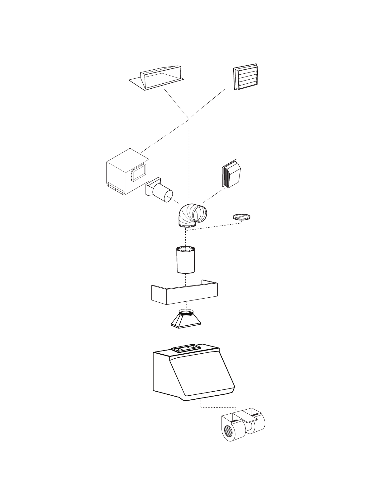
WPD29M
SERIES HOOD
(Canopy with
blower controls
& lighting.
Required for all
installations.)
OPTIONAL
DECORATIVE FLUE
AEWPD SERIES
- WPD29M SERIES RANGE HOOD SYSTEM -
Model 410
(10” round duct—2 ft. sections)
MODEL P12D BLOWER
(1200 cfm interior blower,
sold separately.)
Model 418
(10” round adjustable elbow)
Model EB12 (1200 cfm)
or EB15 (1500 cfm)
exterior blower, sold
separately
Model 421
(10” Round vert.
in-line damper)
Recommended
for use with
exterior blowers
Model SV03428 transition
9” x 18” to 10” round
(Included with hood.)
Model ILB11 (1100 cfm)
in-line blower
(includes two 8” x 12” to
10’’ round transitions)
Model 437
(High capacity roof cap)
Model 441
(10” Round wall cap)
HL0084
Page 4

- 4 -
1. PREPARE THE HOOD LOCATION AND SELECT THE INSTALLATION TYPE
This exhaust hood is designed for use with gas or electric outdoor cooking appliances when operated in an outdoor covered
patio or lanai area. As with all electric appliances, this unit should be protected from the effects of weather as much as possible.
Either an interior or exterior blower or in-line blower may be used with this hood. The Best by Broan WPD29M Series must be
installed with blower models P12D, ILB11, EB12 or EB15 only. Other blowers cannot be substituted. (Blowers sold separately.)
Plan where and how the ductwork will be installed.
If installing ILB11 in-line blower, discard its rough-in plate. Refer to instructions packed with in-line blower and follow
steps 1 up to 6, 8, 9, 10, 11, 13 and up of this manual.
Install 10” round galvanized steel ductwork, elbows and roof or wall cap for the type of blower you are installing. Use metal duct
tape to seal duct joints.
The minimum hood distance above cooktop must not be less than 30’’. A maximum of 36” above cooktop is highly
recommended for best capture of cooking impurities.
Distances over 36” are at the installer and users discretion.
Run power cable to installation location.
MODEL P12D DUAL INTERIOR
BLOWER TYPICAL DUCTWORK
MODEL EB12 OR EB15 EXTERIOR
BLOWER TYPICAL DUCTWORK
HH0075A
30" TO 36" ABOVE
COOKING SURFACE
HOOD
WALL
CAP
ROOF CAP
IN-LINE BLOWER
10" ROUND DUCT
MODEL ILB11 IN-LINE BLOWER
TYPICAL DUCTWORK
WARNING
This unit is not designed for use with a charcoal grill.
!
WARNING
The power cable must be a GFCI protected branch circuit.
!
ROOF CAP
10" ROUND DUCT
OPTIONAL DECORATIVE
FLUE or SOFFIT
10" ROUND ELBOW
HOOD
18"
HH0073A
17 11/16" to
TOP OF WOOD
MOUNTING STRIP
30" TO 36" ABOVE
COOKING SURFACE
WALL CAP
9" x 18" to 10"
ROUND
TRANSITION
INCLUDED
EXTERIOR
10" ROUND DUCT
OPTIONAL DECORATIVE
FLUE or SOFFIT
10" ROUND ELBOW
HOOD
18"
TOP OF WOOD
MOUNTING STRIP
30" TO 36" ABOVE
COOKING SURFACE
HH0074A
17 11/16" to
BLOWER
9" x 18" to 10"
ROUND
TRANSITION
INCLUDED
Page 5

Remove the installation kit from inside the hood.
Make sure that the following items are included:
- Wood strip (screwed on back of hood)
- Installation manual
- Transition (9’’ x 18’’ to 10’’ round)
- Accessories including:
• Baffle filters (3)
• Shielded halogen lights (GU10 type base, 120 V, 50 W) (4 for a 42” width hood, 6 for a 54” width hood)
• Bag of parts including:
(3) waterproof wire connectors, (2) wire clamps, (4) flat head screws #10-2’’, (8) screws #8 x 5/8’’, (8) screws #8 x 3/8’’,
(2) wall anchors, (2) washers 3/16’’ ID x 3/4’’ OD
Parts sold separately:
- Interior blower Model P12D.
- In-line blower assembly ILB11, including transitions and rough-in plate. Discard the rough-in plate.
- Exterior blower assembly EB12 or EB15 (all include rough-in plate). Discard the rough-in plate.
- Duct, elbows, dampers, wall and roof caps. Refer to page 3 for a complete list of venting options and model numbers.
- Optional decorative flue AEWPD Series.
- 5 -
2. PREPARE THE INSTALLATION
CAUTION
When performing installation, servicing or cleaning the unit, it is recommended to wear safety glasses and
gloves.
3. REMOVE THE FILTERS AND THE GREASE DRIP RAIL
A. Remove tape on filters.
Remove filters from hood and set aside.
NOTE: It is recommended to start with the
central one.
B. Remove tape on grease drip rail (1).
Lift out grease drip rail and set aside.
NOTE: When tape is removed in the position as
shown at side, drip rail will possibly fall
out due to gravity.
1
4. REMOVE THE PAN
Using a Phillips no. 2 screwdriver, remove the screws retaining the pan (shaded
part on illustration beside) to the hood. Remove the pan and set aside.
RETAINING SCREWS LOCATION
HD0182
HD0183
Page 6

- 6 -
6. INSTALL WOOD MOUNTING STRIP
Measure and mark a level line on wall above cooktop location for the wood
mounting strip (see illustration on page 4).
Center the wood mounting strip over location. See illustration shown at side.
Use #10, 2’’ flat head screws to secure the mounting strip to the drywall.
Make sure to hit the wall studs.
CAUTION
Due to the weight of this hood, ensure that the wood strip is
attached to every available stud, not into the drywall alone.
7. SELECT BLOWER OPTION (EXTERIOR OR INTERIOR)
INTERIOR BLOWER: Follow all subsequent steps of this manual.
EXTERIOR BLOWER: Discard the exterior blower rough-in plate. Refer to instructions packed with exterior blower and follow
steps 8 to 11, 13 and up of the present manual.
5. REMOVE THE TRANSITION
Using a Phillips no. 2 screwdriver, remove and discard both screws and washers
retaining the transition to the hood. Remove the transition and the wood mounting
strip (on back of hood) and set aside.
R
R
ETAINING
ETAINING
SCREWS
SCREWS
AND
AND
WASHERS
WASHERS
LOCATION
LOCATION
HD0191
1. Drywall
2. Wood mounting strip
3. Flat head screw
4. Wall anchor location
5. Back of hood outline
6. Wall studs
HD0192A
Page 7

- 7 -
8.2 EXTERIOR OR IN-LINE BLOWER:
Pass the power cable and the exterior or in-line blower cable through the wire clamps in the wiring box and tighten the clamps
to secure the cables. DO NOT REMOVE the wire connector joining BLACK and WHITE wires from wiring box receptacle (A).
Using provided waterproof wire connectors, connect wires as follow: BLACK wire from
power cable to BLACK wire from hood control panel (B), all WHITE wires together (C),
BLACK wire from exterior or in-line blower to ORANGE wire from hood control panel (D),
and GREEN or BARE wires under ground screws (E). DO NOT FORGET TO CONNECT
THE GROUND. Reinstall the wiring box cover.
A
B
C
D
E
WATERPROOF WIRE CONNECTORS INSTRUCTIONS:
1. Strip wires 3/8’’.
2. Align frayed strands or conductors.
3. Do not pre-twist. Place stripped wires together with ends even, but lead smaller
stranded wires slightly ahead of larger solid or stranded wire.
4. Twist connector onto wires pushing firmly until hand-tight. DO NOT over torque.
5. When inserting wires into connectors, some sealant may leak out. Wipe off excess
sealant in and around conductors. DO NOT REUSE.
8. CONNECT WIRING
WARNING
Risk of electrical shock. Electrical wiring must be done by qualified personnel in accordance with all
applicable codes and standards. Before connecting wires, switch power off at service panel and lock
service disconnecting means to prevent power from being switched on accidentally.
!
ALL INSTALLATIONS:
Remove the hood wiring box cover. Install wire clamp(s) on back side of the hood. Position the hood below its future location.
NOTE: The hole for the power cable is already done. Punch the other knock-out only if installing exterior blower or in-line blower.
WATERPROOF WIRE CONNECTORS INSTRUCTIONS:
1. Strip wires 3/8’’.
2. Align frayed strands or conductors.
3. Do not pre-twist. Place stripped wires together with ends even, but lead smaller
stranded wires slightly ahead of larger solid or stranded wire.
4. Twist connector onto wires pushing firmly until hand-tight. DO NOT over torque.
5. When inserting wires into connectors, some sealant may leak out. Wipe off excess
sealant in and around conductors. DO NOT REUSE.
Connect wires as follow: BLACK wire from power cable to BLACK wire from hood control
panel (A), all WHITE wires together (B), BLACK wire from wiring box receptacle to ORANGE
wire from hood control panel (C), and GREEN or BARE wire under ground screw (D).
DO NOT FORGET TO CONNECT THE GROUND. Reinstall the wiring box cover.
8.1 INTERIOR BLOWER:
Pass the power cable through the wire clamp in the wiring box and tighten the clamp to secure the cable. Discard the wire connector
joining BLACK and WHITE wires from wiring box receptacle. Connect power cable into wiring box using provided waterproof
wire connectors.
POWER CABLE
EXTERIOR OR IN-LINE
BLOWER
CABLE
POWER CABLE
A
B
C
D
HE0081
HE0080
Page 8

- 8 -
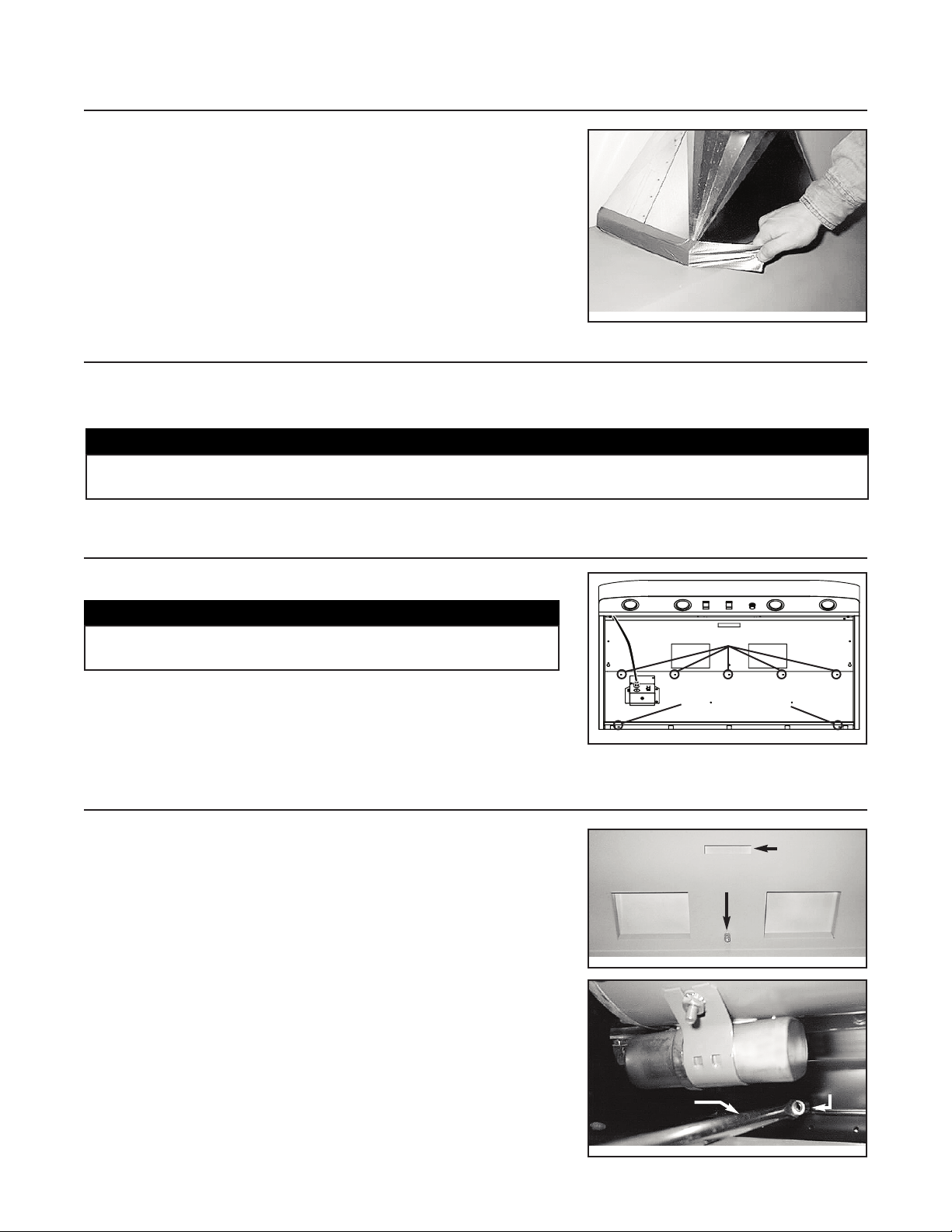
12. INSTALL THE BLOWER (INTERIOR BLOWER ONLY)
Assemble barrel nut (packed with blower) approximately halfway onto threaded
stud on top inside of hood.
Lift blower to top inside of hood. Slide blower back to engage blower tab with slot
in hood top and slot in blower with barrel nut.
HD0061
11. INSTALL THE HOOD
Rest the top back cavity of the hood on the wood mounting strip.
Attach transition to 10” round duct. Secure the hood to wood mounting strip with
(5) screws provided at locations shown. Drill (2) 3/16’’ size holes into the drywall
for wall anchors through the existing holes in the inside hood back in the
locations shown. Then, install the two wall anchors with the remaining #8 x 3/4”
screws and the (2) washers provided.
CAUTION
Hold the hood until it is completely secured to the wood
mounting strip.
TOP OF HOOD (INSIDE VIEW)
M
OUNTING SCREWS LOCATION
SLOT IN TOP
OF HOOD
BARREL NUT ON
THREADED STUD
DISCHARGE
OPENING
DISCHARGE
OPENING
WALL ANCHORS LOCATION
BACK OF HOOD (INSIDE VIEW)
Use a long, flat-bladed screwdriver to tighten the barrel nut securely. Plug motor
into receptacle, on exterior side of wire box.
HD0054
BLOWER MOTOR
FLAT-BLADED
SCREWDRIVER
BARREL NUT
9. INSTALL THE TRANSITION
Attach the provided transition to top of hood. Use metal duct tape to make all
joints secure and air tight.
HD0057
CAUTION
If this decorative flue is installed in a salt water area (example: coast), rinse all surfaces once a week with
clear water (even if the hood is not used), and wipe dry completely.
10. INSTALL THE DECORATIVE FLUE (OPTIONAL)
O
PTIONALDECORATIVEFLUE
AEWPD S
ERIES
Refer to the instructions included with the optional decorative flue.
HD0184
Page 9

- 9 -
Reinstall grease drip rail (1). The illustration beside shows how to reinsert the
grease drip rail into the range hood.
14. REINSTALL GREASE DRIP RAIL AND BAFFLE FILTERS
It is recommended to install side filters first and finish with
center one.
1. Insert one end of baffle filter into the upper channel of the
hood.
2. Raise the other end toward the inside of hood and insert
in the grease drip rail of the hood.
Replacement filters are available from your dealer. See label
inside hood for size and part number.
CAUTION
Remove protective plastic film covering baffle filters before installing them.
1
13. REINSTALL THE PAN
Using a Phillips no. 2 screwdriver and the retaining screws, reinstall the pan
(previously removed in step 5) inside the hood (shaded part on illustration
beside).
RETAINING SCREWS LOCATION
HD0183
HD0185
1
HD0189
2
Page 10
- 10 -
Grease Drip Rail
The grease drip rail should be cleaned frequently. Lift it out from the hood and use a warm detergent solution. Wash more often
if your cooking style generates greater grease—like frying foods or wok cooking. Allow grease drip rail to dry completely before
reinstalling it in the hood.
Blower Cleaning
Remove the filters in order to access the blower. Vacuum blower to clean. Do not immerse in water. Refer to blower instruction
manual for more details.
Hood Cleaning
Stainless steel cleaning: How to maintain its “BRIGHT LOOK”
Do:
• Regularly wash with clean cloth or rag soaked with warm water and mild soap or liquid dish detergent.
• Always clean in the direction of original polish lines.
• Always rinse well with clear water (2 or 3 times) after cleaning. Wipe dry completely.
• You may also use a specialized household stainless steel cleaner.
Don’t:
• Do not use any steel or stainless steel wool or any other scrapers to remove stubborn dirt.
• Do not use any harsh or abrasive cleansers.
• Do not allow dirt to accumulate.
• Do not let plaster dust or any other construction residues reach the hood. During construction/renovation, cover the hood to
make sure no dust sticks to stainless steel surface.
Avoid: When choosing a detergent
• Any cleaners that contain bleach will attack stainless steel.
• Any products containing: chloride, fluoride, iodide, bromide will deteriorate surfaces rapidly.
• Any combustible products used for cleaning such as acetone, alcohol, ether, benzol, etc., are highly explosive and should
never be used close to a range.
16. USE AND CARE
Baffle Filters
The baffle filters should be cleaned frequently. Use a warm detergent solution. Wash more often if your cooking style generates
greater grease—like frying foods or wok cooking.
Remove filters by pushing them towards the back of hood and rotating filters downward. Baffle filters are dishwasher safe.
Allow filters to dry completely before reinstalling them in the hood.
CAUTION
If this hood is installed in a salt water area (example: coast), rinse all surfaces once a week with clear water
(even if the hood is not used), and wipe dry completely.
15. LIGHT BULBS REPLACEMENT
This hood must use 120 V, 50 W, MR16 with GU10 base or PAR16 with GU10 base, shielded halogen lamps (included).
WARNING
In order to prevent the risk of personal injury, do not install a lamp identified for use only in enclosed
fixtures.
!
WARNING
In order to prevent the risk of personal injury, the halogen lamps must be cooled down before removing them.
!
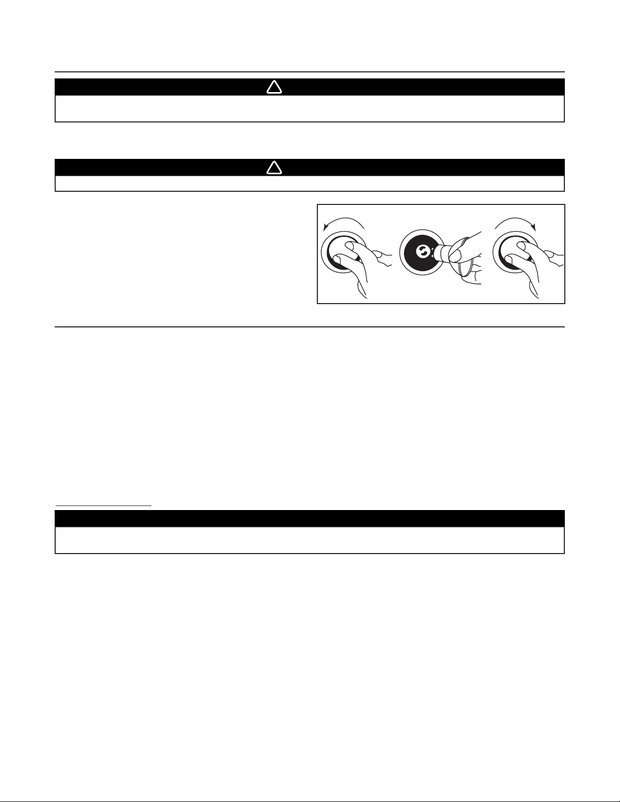
1. To remove lamps, gently push upwards and turn counterclockwise
to disengage bulb leads from their grooves.
NOTE: If need be, use a rubber dishwashing glove to add grip
when removing the bulb.
2. Install the new lamps by placing the bulb leads into their
grooves in the socket.
3. Gently push upwards and turn clockwise until secure.
12 3
HO0089
Page 11

- 11 -
17. OPERATION
The hood is operated using the (3) controls located beneath the front edge of the hood.
1. Light switch
2. Blower ON/OFF switch
3. Blower speed control
Light switch
The light switch turns the halogen lights ON and OFF.
Use 120 V, 50 W, MR16 with GU10 base or PAR16 with GU10 base, shielded halogen lamps (included).
Blower ON/OFF switch
The blower is operated using two (2) controls.
The blower ON/OFF switch turns the blower ON to the speed preset by the speed control (item 3 on picture above).
The blower must be turned ON and OFF using this switch.
Blower speed control
Turn the speed control knob counterclockwise to increase blower speed—clockwise to decrease speed.
HEAT SENTRY
This hood is equipped with a HEAT SENTRY thermostat. This thermostat is a device that will speed up the blower if it senses
excessive heat above the cooking surface.
If blower is ON at a lower speed setting—it turns the blower up to HIGH speed.
When the temperature level drops to normal, the blower will return to its original setting.
Using hood with a covered gas grille
When opening the cover on your gas grille, you may notice a reduction in the capture of smoke and steam.
WARRANTY
BROAN ONE-YEAR LIMITED WARRANTY
Broan warrants to the original consumer purchaser of its products that such products will be free from defects in materials
or workmanship for a period of one year from the date of original purchase. THERE ARE NO OTHER WARRANTIES,
EXPRESS OR IMPLIED, INCLUDING, BUT NOT LIMITED TO, IMPLIED WARRANTIES OR MERCHANTABILITY OR
FITNESS FOR A PARTICULAR PURPOSE.
During this one-year period, Broan will, at its option, repair or replace, without charge, any product or part which is found to
be defective under normal use and service.
This warranty does not cover (a) normal maintenance and service or (b) any products or parts which have been subject to
misuse, negligence, accident, improper maintenance or repair (other than by Broan), faulty installation or installation contrary
to recommended installation instructions.
The duration of any implied warranty is limited to the one-year period as specified for the express warranty. Some states or
provinces do not allow limitation on how long an implied warranty lasts, so the above limitation may not apply to you.
BROAN’S OBLIGATION TO REPAIR OR REPLACE, AT BROAN’S OPTION, SHALL BE THE PURCHASER’S SOLE AND
EXCLUSIVE REMEDY UNDER THIS WARRANTY. BROAN SHALL NOT BE LIABLE FOR INCIDENTAL, CONSEQUENTIAL
OR SPECIAL DAMAGES ARISING OUT OF OR IN CONNECTION WITH PRODUCT USE OR PERFORMANCE. Some
states or provinces do not allow the exclusion or limitation of incidental or consequential damages, so the above
limitation or exclusion may not apply to you.
This warranty gives you specific legal rights, and you may also have other rights, which vary from state to state or province to
another. Any modification performed on this product without the authorization of Broan will void this warranty. This warranty
supersedes all prior warranties.
To qualify for warranty service, you must (a) notify Broan at the address or telephone number stated below, (b) give the model
number and part identification and (c) describe the nature of any defect in the product or part. At the time of requesting
warranty service, you must present evidence of the original purchase date.
Best by Broan®, P.O. Box 140, Hartford, WI 53027 USA (1-800-637-1453)
Best by Broan®, 550 Lemire Blvd., Drummondville, QC J2C 7W9 CANADA (1-866-737-7770)
HC0014
1
2 3
O
Page 12

- 12 -
SERVICE PARTS
KEY PART QTY (HOOD WIDTH)
NO. NUMBER DESCRIPTION 42’’ 54’’
1 V03428 T
RANSITION 9” X 18” X 10” ROUND 11
2 V16765 L
AMP SHELL, SOCKET OUTDOOR AND TRIM ASS’Y GU-10 4 6
3 V05921 H
ALOGEN BULBS (50 W, 120 V, PAR16, GU-10) 4 6
4 V06497 T
HERMISTOR HEAT SENTRY 11
5 V06364 R
OTARY SPEED CONTROL 11
6 V03504 B
LOWER SPEED CONTROL KNOB 11
7 V06495 L
IGHT SWITCH 11
8 V06496 B
LOWER SWITCH 11
9
V16939 B
AFFLE FILTERS 8.95” X 8.61” X 1” 2 -
V16940 B
AFFLE FILTERS 14.95” X 8.61” X 1” 1 3
10 V15432 F
ILTER SPRING CLIP 33
11
V16958 G
REASE DRIP RAIL 36”, SS316 1 -
V16964 G
REASE DRIP RAIL 48”, SS316 - 1
12
V16996 I
NSIDE FRAME ASS’Y (42” X 24” X 18”) (INCLUDING ITEM 10) 1 -
V16997 I
NSIDE FRAME ASS’Y (54” X 24” X 18”) (INCLUDING ITEM 10) - 1
* V07697 I
NSTALLATION GUIDE 11
P
ARTS BAG (WATERPROOF WIRE CONNECTOR (3),
* V04216
W
IRE CLAMPS LP16-AP (2), SCREWS #8 X 5/8’’ (8),
11
S
CREWS #8 X 3/8’’ (8), FLAT HEAD SCREW #10 X 2’’ (4),
W
ALL ANCHORS (2), WASHERS 3/16’’ ID X 3/4’’ OD (2))
*V05869 B
EST BY BROAN LOGO 11
* V06933 E
LECTRICAL HARNESS 11
*N
OT SHOWN.
WPD29M
MODEL
3
2
10
4
1
11
5
6
7
8
9
12
HL0085
Page 13

CONÇUE UNIQUEMENT POUR USAGE DOMESTIQUE
INSTALLATEUR : LAISSER CE MANUEL AU PROPRIÉTAIRE.
PROPRIÉTAIRE : DIRECTIVES D’UTILISATION ET D’ENTRETIEN AUX PAGES 22
ET 23.
GUIDE D’INSTALLATION
LIRE ET CONSERVER CES INSTRUCTIONS
!
!
SÉRIE WPD29M
V07697 rév. A
Aux États-Unis — BEST BY BROAN®P.O. Box 140, Hartford, WI 53027 USA
Au Canada — BEST BY BROAN
®
550, boul. Lemire, Drummondville (Québec) J2C 7W9 CANADA
Pour obtenir plus d’information, consultez notre site www.bestbybroan.com
CONVIENT À UNE INSTALLATION DANS DES LIEUX HUMIDES LORSQU’ELLE EST
RACCORDÉE À UN DISJONCTEUR DE MISE À LA TERRE (DDFT).
C
ONÇUE POUR FONCTIONNER SUR UN PATIO COUVERT OU UNE VÉRANDA.
HB0059
Page 14

- 14 -
AVERTISSEMENT AVERTISSEMENT
AFIN DE RÉDUIRE LE RISQUE D’INCENDIE,
D’ÉLECTROCUTION OU DE BLESSURES CORPORELLES,
SUIVEZ LES INSTRUCTIONS SUIVANTES :
1. N’utilisez cet appareil que de la façon prévue par
le manufacturier. Si vous avez des questions,
contactez le manufacturier à l’adresse et au
numéro de téléphone indiqués dans la garantie.
2. Avant de réparer ou de nettoyer l’appareil, coupez
l’alimentation électrique en verrouillant le panneau de
service afin d’éviter sa remise en marche accidentelle.
Si le panneau de service ne peut être verrouillé, y
fixer un avertissement en évidence.
3. Les travaux d’installation et de raccordement
électrique doivent être effectués par du personnel
qualifié, conformément aux codes et aux standards
de construction, incluant ceux concernant le feu.
4. Une quantité d’air adéquate est requise afin d’assurer
une bonne combustion et l’évacuation des gaz par
la cheminée dans le cas des équipements alimentés
au gaz afin de prévenir les retours de cheminée.
Conformez-vous aux instructions et aux standards
de sécurité des manufacturiers d’équipement de
chauffage, tels qu’ils sont publiés par la National
Fire Protection Association (NFPA) et l’American
Society for Heating, Refrigeration and Air
Conditioning Engineers (ASHRAE) ainsi que les
responsables des codes locaux.
5. Lorsque vous coupez ou perforez un mur ou un
plafond, prenez garde de ne pas endommager
les fils électriques ou tout appareil dissimulé.
6. Les ventilateurs avec conduits doivent toujours
évacuer l’air à l’extérieur.
7. Ne pas utiliser cet appareil avec une commande
de vitesse à semi-conducteur additionnelle.
8. Afin de réduire les risques d’incendie, n’utilisez
que des conduits de métal.
9. Cet appareil doit être mis à la terre et protégé par
un DDFT (disjoncteur de fuite à la terre).
10. Convient à une utilisation dans des lieux humides
seulement lorsqu’elle est raccordée à un
DISJONCTEUR DE FUITE À LA TERRE (DDFT).
11. Cet appareil n’est pas conçu pour être utilisé avec
un barbecue.
AFIN DE RÉDUIRE LE RISQUE DE FEU
DE CUISINIÈRE :
a) Ne laissez jamais les appareils de cuisson sans
surveillance lorsqu’ils sont réglés à feu vif.
Les débordements engendrent de la fumée et des
déversements graisseux pouvant s’enflammer.
Chauffez l’huile lentement, à feu doux ou moyen.
b) Mettez toujours la hotte en marche lorsque vous
cuisinez à feu vif ou que vous cuisinez des
mets flambés (crêpes Suzette, cerises jubilé,
steaks au poivre flambé).
c) Nettoyez régulièrement la (les) roue(s) du ventilateur.
Ne laissez pas la graisse s’accumuler sur le
ventilateur ou les filtres.
d) Utilisez le bon format de casserole. Servez-vous
toujours de casseroles et d’ustensiles appropriés à
la dimension de la surface chauffante.
AFIN D’ÉVITER TOUT RISQUE DE BLESSURES
DANS LE CAS D’UN FEU DE CUISINIÈRE, SUIVEZ
CES DIRECTIVES* :
1. Étouffez les flammes avec un couvercle hermétique,
une tôle à biscuits ou un plateau métallique et
ensuite, éteindre le brûleur. PRENEZ SOIN
D’ÉVITER LES BRÛLURES. SI LES FLAMMES
NE S’ÉTEIGNENT PAS IMMÉDIATEMENT,
ÉVACUEZ LES LIEUX ET APPELEZ LES POMPIERS.
2. NE PRENEZ JAMAIS UNE CASSEROLE EN
FLAMMES DANS VOS MAINS. Vous pourriez
vous brûler.
3. N’UTILISEZ PAS D’EAU, incluant linge à vaisselle
ou serviette mouillés; cela pourrait occasionner
une violente explosion de vapeur.
4. N’utilisez un extincteur QUE DANS LE CAS OÙ :
A. Vous savez qu’il s’agit d’un extincteur de classe ABC
et que vous en connaissez le fonctionnement.
B. L’incendie est petit et limité à l’endroit où il a débuté.
C. Les pompiers ont été avisés.
D. Vous pouvez combattre l’incendie en ayant
accès à une sortie de secours.
*Tirées du
Kitchen Fire Safety Tips
publié par la NFPA.
ATTENTION
1. Pour usage domestique seulement. Ne l’utilisez
pas pour évacuer des vapeurs ou des matières
dangereuses ou explosives.
2. Afin d’éviter tout dommage au moteur et de
débalancer ou de rendre bruyante la roue du
moteur, gardez votre appareil à l’abri des poussières
de gypse et de construction/rénovation, etc.
3. Le moteur de votre hotte possède une protection
thermique qui éteindra automatiquement le moteur s’il
devient surchauffé. Le moteur repartira automatiquement
une fois refroidi. Si le moteur continue à arrêter et
à repartir, faites-le vérifier.
4. Pour une meilleure évacuation des odeurs de cuisson,
le bas de votre hotte devrait être situé à un minimum
de 30 po et à un maximum de 36 po au-dessus de
la table de cuisson.
5. Deux installateurs sont recommandés lors de l’installation
vu la grande dimension et le poids de cette hotte.
6. Afin de réduire les risques d’incendie, assurez-vous
d’évacuer l’air à l’extérieur. Ne pas évacuer l’air
dans des espaces restreints comme l’intérieur des
murs ou plafond ou dans le grenier, vide sanitaire
ou garage.
7. Cet appareil est équipé d’un thermostat pouvant
faire démarrer le ventilateur automatiquement.
Afin de réduire le risque de blessures, couper le
courant à partir du panneau électrique et
verrouiller ou apposer un avertissement sur le
panneau afin de prévenir que la hotte soit mise en
marche automatiquement.
8. Afin de réduire les risques d’incendie et d’électrocution,
la hotte Best by Broan de série WPD29M doit être
installée uniquement avec le ventilateur
intérieur Best by Broan P12D; un des ventilateurs
extérieurs Best by Broan suivants : EB12 ou EB15,
ou le ventilateur en ligne Best by Broan ILB11
(vendus séparément). Aucun autre ventilateur ne
doit être utilisé.
9. Veuillez consulter l’autocollant apposé à l’intérieur
de la hotte pour plus d’information ou autres exigences.
!
!
Page 15

- 15 -
HOTTE SÉRIE
WPD29M
(Avec commandes
ventilateur et
éclairage. Requise
pour toutes
les installations.)
CHEMINÉE DÉCORATIVE
OPTIONNELLE SÉRIE AEWPD
- SYSTÈME DE HOTTE DE CUISINIÈRE SÉRIE WPD29M -
Modèle 437
(Capuchon de toit à haut rendement)
Modèle 441
(Capuchon de toit
de 10 po rond)
Modèle 410
(Conduit de 10 po rond,
sections de 2 pi)
MODÈLE P12D
VENTILATEUR
(Ventilateur intérieur
de 1200 pcm,
vendu séparément)
Modèle 418
(Coude ajustable
de 10 po rond)
Modèle SV03428,
transition ronde de
9 po x 18 po à 10 po
(Incluse avec la hotte.)
Modèle 421
(Volet intérieur de
10 po rond vert.)
Recommandé
pour utilisation
avec ventilateurs
extérieurs
Ventilateur extérieur
modèle EB12 (1200 pcm)
ou EB15 (1500 pcm),
vendus séparément
Ventilateur en ligne
modèle ILB11 (1100 pcm)
(incluant deux transitions
rondes de 8 po x 12 po à 10 po)
HL0084
Page 16

- 16 -
1. PRÉPARER L’EMPLACEMENT DE LA HOTTE ET CHOISIR LE TYPE D’INSTALLATION
Cette hotte de cuisinière a été conçue pour fonctionner avec une cuisinière électrique ou à gaz, lorsqu’elle est utilisée sur un patio
couvert ou une véranda. Comme tous les électroménagers, cet appareil doit, autant que possible, être à l’abri des intempéries.
Cette hotte fonctionne autant avec un ventilateur intérieur, en ligne ou extérieur. La hotte de modèle Best by Broan de série
WPD29M doit être installée uniquement avec l’un des ventilateurs suivants : P12D, ILB11, EB12 ou EB15 (vendus séparément).
Aucun autre ventilateur ne peut être utilisé.
Déterminer à quel endroit et de quelle façon les conduits seront installés.
Si le ventilateur en ligne ILB11 est installé, ne pas utiliser sa plaque ventilateur. Se reporter aux directives incluses
avec celui-ci et suivre les étapes 1 à 6, 8 à 11, 13 et suivantes de ce guide.
Installer des conduits circulaires de 10 po en acier galvanizé, coude(s) et capuchon de mur ou de toit selon le type de ventilateur.
Se servir de ruban adhésif pour conduits en métal pour assurer l’étanchéité des joints.
La distance minimale entre le bas de votre hotte et la surface de cuisson ne doit pas être inférieure à 30 po. Un maximum
de 36 po au-dessus de la surface de cuisson est fortement recommandé pour une meilleure évacuation des odeurs
de cuisson.
Une distance de plus de 36 po demeure à la discrétion de l’installateur et de l’utilisateur.
Passer l’alimentation électrique jusqu’à l’emplacement de l’installation.
18 po
CAPUCHON
DE MUR
DE 30 po À 36 po
AU-D ESSUS DE LA
SURFACE DE CUISSON
DISTANCE
DE 17 11/16 po
JUSQU’AU
DESSUS DE LA
LISIÈRE DE BOIS
HOTTE
CHEMINÉE DÉCORATIVE
OPTIONNELLE OU SOFFITE
TRANSITION
RONDE DE
9 po x 18 po à 10 po
(INCLUSE)
HH0073F
CAPUCHON
DE TOIT
CONDUIT ROND
DE 10 po
COUDE ROND DE 10 po
o
INSTALLATION TYPIQUE
VENTILATEUR INTÉRIEUR DOUBLE
MODÈLE P12D
INSTALLATION TYPIQUE
VENTILATEUR EXTÉRIEUR
MODÈLE EB12 OU EB15
HH0075F
DE 30 po À 36 po AU-DESSUS
DE LA SURFACE
DE CUISSON
HOTTE
CAPUCHON
DE MUR
CONDUIT ROND
DE 10 po
VENTILATEUR
EN LIGNE
CAPUCHON
DE TOIT
INSTALLATION TYPIQUE
VENTILATEUR EN LIGNE
MODÈLE ILB11
AVERTISSEMENT
Cet appareil n’est pas conçu pour être utilisé avec un barbecue.
!
AVERTISSEMENT
Le fil d’alimentation électrique doit être raccordé à un disjoncteur de fuite à la terre (DDFT).
!
VENTILATEUR
CONDUIT ROND
DE 10 po
CHEMINÉE DÉCORATIVE
OPTIONNELLE OU SOFFITE
COUDE ROND DE 10 po
DISTAN C E
DE 17 11/16 po
JUSQU’AU
DESSUS DE LA
LISIÈRE DE BOIS
DE 30 po À 36 po
18 po
SURFACE DE CUISSON
HH0074F
HOTTE
AU-D ESSUS DE LA
EXTÉRIEUR
TRANSITION
RONDE DE
9 po x 18 po à 10 p
(INCLUSE)
Page 17

- 17 -
Retirer la trousse d’installation de l’intérieur de la hotte.
S’assurer que les articles suivants sont inclus :
- Lisière de bois
- Guide d’installation
- Transition (9 po x 18 po à 10 po ronde)
- Les accessoires incluant :
• Les filtres à chicanes (3)
• Ampoules halogènes avec écran (20 V, 50 W, avec culot GU10) (4 pour une hotte de 42 po de largeur, 6 pour une hotte
de 54 po de largeur)
• Le sac de pièces incluant :
(3) connecteurs étanches, (2) serre-fils, (4) vis à tête plate n
o
10-2 po, (8) vis no8 x 5/8 po, (8) vis no8 x 3/8 po,
(2) ancrages de gypse, (2) rondelles 3/16 po DI x 3/4 po DE
Pièces vendues séparément :
- Ventilateur intérieur modèle P12D.
- Ensemble de ventilateur en ligne, modèle ILB11, incluant les transitions et la plaque ventilateur. Ne pas utiliser la plaque ventilateur.
- Ensemble de ventilateur extérieur, modèle EB12 ou EB15 (tous incluant la plaque ventilateur). Ne pas utiliser la plaque ventilateur.
- Conduits, coudes, volets, capuchons de mur ou de toit. Consulter la page 15 pour la liste complète des accessoires de
ventilation et les numéros de modèle.
- Cheminée décorative optionnelle série AEWPD.
2. PRÉPARER L’INSTALLATION
ATTENTION
Il est recommandé de porter des lunettes et des gants de sécurité lors de l’installation, de l’entretien ou
de la réparation de cet appareil.
3. RETIRER LES FILTRES ET LA GOUTTIÈRE
A. Enlever le ruban des filtres.
Retirer les filtres de la hotte et les mettre
de côté.
NOTE :Il est recommandé de retirer le filtre
central en premier.
B. Enlever le ruban de la gouttière (1).
Dégager la gouttière de la hotte et la mettre
de côté.
NOTE : Lorsque la hotte est dans la position
démontrée ci-contre et que l’on retire le
ruban, il se peut que la gravité fasse
tomber la gouttière.
1
4. RETIRER LE CADRE INTÉRIEUR
À l’aide d’un tournevis Phillips no2, enlever les vis retenant le cadre intérieur
(la pièce colorée en gris dans l’illustration ci-contre) à la hotte. Retirer le cadre
intérieur et le mettre de côté.
EMPLACEMENT DES VIS DE RETENUE
HD0182
HD0183
Page 18

- 18 -
6. INSTALLER LA LISIÈRE DE BOIS
Mesurer et tracer une ligne droite au-dessus de la surface de cuisson pour
l’emplacement de la lisière de bois (voir l’illustration en page 16).
Centrer la lisière de bois, voir l’illustration ci-contre. Fixer la lisière de bois au mur
à l’aide des vis à tête plate n
o
10-2 po en s’assurant d’atteindre les montants.
ATTENTION
Vu le poids élevé de cette hotte, s’assurer que la lisière de bois
soit bien rattachée à tous les montants disponibles. Ne pas
visser la lisière de bois uniquement au mur.
7. CHOISIR L’OPTION VENTILATEUR (EXTÉRIEUR OU INTÉRIEUR)
VENTILATEUR INTÉRIEUR : Suivre toutes les étapes subséquentes de ce guide.
VENTILATEUR EXTÉRIEUR : Ne pas utiliser la plaque ventilateur. Voir les instructions fournies avec le ventilateur extérieur
et suivre les étapes 8 à 11, 13 et suivantes du présent guide.
5. RETIRER LA TRANSITION
À l’aide d’un tournevis Phillips no2, retirer et jeter les deux vis et rondelles
retenant la transition à l’intérieur de la hotte. Retirer la transition ainsi que la
lisière de bois (au dos de la hotte) et mettre de côté.
E
E
MPLACEMENT
MPLACEMENT
DES
DES
VIS
VISETET
RONDELLES
RONDELLESDEDE
RETENUE
RETENUE
HD0191
1. Mur 4. Localisation des ancrages de gypse
2. Lisière de bois 5. Tracé de l’arrière de la hotte
3. Vis à tête fraisée 6. Montants
HD0192F
Page 19

- 19 -
8.2 VENTILATEUR EXTÉRIEUR OU EN LIGNE :
Par les serre-fils, insérer le câble d’alimentation électrique et le fil du ventilateur extérieur ou en ligne dans le boîtier électrique
et serrer les serre-fils pour les maintenir en place. NE PAS ENLEVER le connecteur reliant les fils NOIR et BLANC (A) de l’intérieur
du boîtier électrique.
À l’aide des connecteurs étanches fournis, connecter les fils comme suit : le fil NOIR du
câble d’alimentation électrique avec le fil NOIR du panneau de contrôle de la hotte (B),
tous les fils BLANCS ensemble (C), le fil NOIR du ventilateur extérieur ou en ligne avec
le fil ORANGE du panneau de contrôle de la hotte (D), et les fils VERTS ou DÉNUDÉS
sous les vis de mise à la terre (E). NE PAS OUBLIER DE BRANCHER LA MISE À LA
TERRE. Remettre en place le couvercle du boîtier électrique.
A
B
C
D
E
DIRECTIVES POUR L’UTILISATION DES CONNECTEURS ÉTANCHES :
1. Dégainer les fils d’une longueur de 3/8 po.
2. Égaliser les brins ou les conducteurs.
3. Ne pas les tordre. Rapprocher les fils et mettre leurs bouts égaux, sauf pour les
fils à brins plus petits, lesquels doivent dépasser légèrement des fils plus gros.
4. Insérer les fils dans le connecteur en poussant légèrement et tordre. NE PAS
trop tordre.
5. Un peu de scellant pourrait s’échapper lors de l’insertion des fils dans un
connecteur. Essuyer l’excès de scellant autour des conducteurs.
NE PAS RÉUTILISER.
8. BRANCHEMENT ÉLECTRIQUE
AVERTISSEMENT
Risque d’électrocution. Le raccordement électrique doit être effectué par du personnel qualifié conformément
aux codes et aux standards. Avant d’effectuer le branchement, coupez l’alimentation électrique au panneau
de service et verrouillez-le pour éviter une mise en marche accidentelle.
!
DIRECTIVES POUR L’UTILISATION DES CONNECTEURS ÉTANCHES :
1. Dégainer les fils d’une longueur de 3/8 po.
2. Égaliser les brins ou les conducteurs.
3. Ne pas les tordre. Rapprocher les fils et mettre leurs bouts égaux, sauf pour les
fils à brins plus petits, lesquels doivent dépasser légèrement des fils plus gros.
4. Insérer les fils dans le connecteur en poussant légèrement et tordre. NE PAS
trop tordre.
5. Un peu de scellant pourrait s’échapper lors de l’insertion des fils dans un
connecteur. Essuyer l’excès de scellant autour des conducteurs.
NE PAS RÉUTILISER.
Connecter les fils comme suit : le fil NOIR du câble d’alimentation électrique avec le fil
NOIR du panneau de contrôle de la hotte (A), tous les fils BLANCS ensemble (B), le fil
NOIR du boîtier électrique avec le fil ORANGE du panneau de contrôle de la hotte (C),
et le fil VERT ou DÉNUDÉ sous la vis de mise à la terre (D). NE PAS OUBLIER DE
BRANCHER LA MISE À LA TERRE. Remettre en place le couvercle du boîtier électrique.
FIL DU VENTILATEUR
EXTÉRIEUR OU
EN LIGNE
CÂBLE D’ALIMENTATION
ÉLECTRIQUE
A
B
C
D
TOUTES LES INSTALLATIONS :
Retirer le couvercle du boîtier électrique. Installer le(s) serre-fils au dos de la hotte. Placer la hotte près de son futur emplacement.
NOTE : Le trou d’accès pour le fil d’alimentation électrique existe déjà. Perforer l’ouverture préamorcée seulement si un
ventilateur extérieur ou en ligne sera installé.
8.1 VENTILATEUR INTÉRIEUR :
Par le serre-fils, insérer le câble d’alimentation électrique dans le boîtier électrique et serrer le serre-fils pour le maintenir en place.
Se défaire du connecteur reliant les fils NOIR et BLANC de l’intérieur du boîtier électrique. Connecter les fils du câble
d’alimentation électrique au boîtier électrique à l’aide des connecteurs étanches fournis.
CÂBLE
D’ALIMENTATION
ÉLECTRIQUE
HE0081
HE0080
Page 20
- 20 -
12. INSTALLER LE VENTILATEUR (VENTILATEUR INTÉRIEUR SEULEMENT)
Engager l’écrou cylindrique (fourni avec le ventilateur) environ à mi-chemin sur
la tige filetée située sur le dessus intérieur de la hotte.
Soulever le ventilateur à l’intérieur de la hotte, puis le glisser vers l’arrière de
façon à engager la patte du ventilateur dans la fente du dessus de la hotte, et la
tige filetée et son écrou dans la fente du ventilateur.
HD0061
11. INSTALLER LA HOTTE
En appuyant la hotte au mur, insérer la lisière de bois dans la cavité arrière de la hotte.
Attacher la transition au conduit rond de 10 po. Fixer la hotte à la lisière de bois
aux endroits indiqués à l’aide de (4) vis fournies. En se servant des trous existants
dans la hotte, percer le mur aux endroits indiqués de (2) trous de 3/16 po pour
les ancrages de gypse. Puis, insérer les (2) ancrages de gypse et fixer la hotte à
ces ancrages avec les (2) vis n
o
8 x 3/4 po restantes et les (2) rondelles fournies.
ATTENTION
Retenir la hotte jusqu’à ce qu’elle soit complètement vissée à la
lisière de bois.
FENTE SUR
LE DESSUS
DE LA HOTTE
ÉCROU CYLINDRIQUE
SUR TIGE FILETÉE
OUVERTURE
D’ÉVACUATION
OUVERTURE
D
’ÉVACUATION
À l’aide d’un long tournevis à lame plate, visser complètement l’écrou à la tige
filetée. Brancher le cordon du moteur à sa prise, sur le boîtier électrique.
HD0054
MOTEUR DU VENTILATEUR
TOURNEVIS À
LAME PLATE
ÉCROU
CYLINDRIQUE
9. INSTALLER LA TRANSITION
Installer la transition sur le dessus de la hotte. Sceller les joints avec du ruban à
conduit en métal.
HD0057
ATTENTION
Si cette cheminée décorative est installée dans un environnement salin (ex. : la côte), rincer à l’eau claire
toutes les surfaces une fois par semaine (même si la hotte n’est pas utilisée) et essuyer complètement.
10. INSTALLER LA CHEMINÉE DÉCORATIVE (OPTIONNELLE)
C
HEMINÉE DÉCORATIVE OPTIONNELLE DE SÉRIE
AEWPD
Voir les directives incluses avec la cheminée décorative optionnelle.
EMPLACEMENT DES VIS
DESSUS DE LA HOTTE (VUE INTÉRIEURE)
A
RRIÈREDELAHOTTE(VUE INTÉRIEURE)
E
MPLACEMENT DES
ANCRAGES DE GYPSE
HD0184
Page 21

- 21 -
Réinstaller la gouttière (1). L’image ci-contre illustre la façon de réinsérer la gouttière
dans la hotte.
14. RÉINSTALLER LA GOUTTIÈRE ET LES FILTRES
Il est recommandé d’installer d’abord les filtres situés aux
extrémités et de terminer avec celui du centre.
1. Introduire une extrémité du filtre dans le rail supérieur de
la hotte.
2. Lever l’autre bout du filtre à l’intérieur de la hotte et
l’introduire dans la gouttière.
Des filtres de rechange sont offerts chez votre marchand.
Consulter l’étiquette à l’intérieur de la hotte pour connaître le
format et le numéro de pièce des filtres.
ATTENTION
Avant d’installer les filtres à chicanes, retirer la pellicule de plastique protectrice de ceux-ci.
1
13. REMETTRE EN PLACE LE CADRE INTÉRIEUR
À l’aide d’un tournevis Phillips no2 et de ses vis, remettre en place le cadre
intérieur (retiré précédemment à l’étape 5) à l’intérieur de la hotte (la pièce
colorée en gris dans l’illustration ci-contre).
EMPLACEMENT DES VIS
HD0183
HD0185
1
HD0189
2
Page 22

- 22 -
15. REMPLACEMENT DES LAMPES HALOGÈNES
Cette hotte utilise des ampoules halogènes avec écran (120 V, 50 W, MR16 avec culot GU10, ou PAR16 avec culot GU10) incluses.
AVERTISSEMENT
Afin de réduire le risque de blessures corporelles, ne pas installer une ampoule conçue uniquement pour
des luminaires fermés.
!
AVERTISSEMENT
Afin de réduire le risque de blessures corporelles, attendre que l’ampoule halogène soit refroidie avant de
la retirer.
!
1. Pour retirer les ampoules, pousser doucement vers le haut et
tourner dans le sens contraire des aiguilles d’une montre pour
désengager les conducteurs hors de leur rainure.
NOTE : Si nécessaire, utiliser un gant à vaisselle pour obtenir
une meilleure prise de l’ampoule lors de son retrait.
2. Installer les nouvelles ampoules en glissant leurs conducteurs
dans les rainures, à l’intérieur des douilles.
3. Pousser doucement vers le haut et tourner dans le sens des aiguilles
d’une montre jusqu’à ce que les ampoules soient bien en place.
16. ENTRETIEN
Filtres à chicanes
Les filtres à chicanes doivent être nettoyés fréquemment. Utiliser une solution d’eau chaude et de détergent. Les filtres à chicanes
doivent être lavés plus souvent si vos habitudes de cuisson génèrent plus de graisse, par exemple de la
friture ou des aliments sautés au wok.
Retirer les filtres en les poussant vers l’arrière de la hotte et en les retournant vers le bas. Les filtres à chicanes sont lavables
au lave-vaisselle. Laisser les filtres sécher complètement avant de les réinstaller dans la hotte.
Gouttière
La gouttière doit être nettoyée fréquemment. Pour ce faire, la désengager de la hotte et utiliser une solution d’eau chaude et de
détergent. Tout comme les filtres à chicanes, la laver plus souvent si vos habitudes de cuisson génèrent plus de graisse, par
exemple de la friture ou des aliments sautés au wok. Essuyer complètement la gouttière avant de la réinstaller dans la hotte.
Nettoyage du ventilateur
Retirer les filtres pour accéder au ventilateur. Passer l’aspirateur pour le nettoyer, ne pas l’immerger dans l’eau. Pour plus de
détails, consulter le guide d’installation du ventilateur.
Nettoyage de la hotte
Acier inoxydable : Comment préserver son « APPARENCE ÉTINCELANTE » :
À faire :
• Laver régulièrement les surfaces à l’aide d’un linge propre ou d’un chiffon imbibé d’eau tiède et de savon doux ou de détergent
liquide pour vaisselle.
• Toujours nettoyer dans le sens du polissage.
• Toujours bien rincer avec de l’eau claire (2 à 3 fois) et essuyer complètement.
• Un nettoyant domestique conçu spécialement pour l’acier inoxydable peut aussi être utilisé.
À ne pas faire :
• Ne pas utiliser de laine d’acier ou d’acier inoxydable ou tout autre grattoir pour enlever la saleté tenace.
• Ne pas utiliser une poudre nettoyante abrasive ou rugueuse.
• Ne pas laisser la saleté s’accumuler.
• Ne pas laisser la poussière de plâtre ou tout autre résidu de construction atteindre la hotte. Couvrir la hotte pour la durée
des travaux afin de s’assurer qu’aucune poussière n’atteigne la hotte.
À éviter lors du choix du détergent :
• Tous produits nettoyants contenant des agents de blanchiment; ils attaqueront l’acier inoxydable.
• Tous les produits contenant du chlorure, du fluorure, de l’iode ou du bromure; ils détérioreront rapidement les surfaces.
• Tous produits combustibles utilisés pour le nettoyage : acétone, alcool, éther, benzol, etc., ils sont hautement explosifs et
ne devraient jamais être utilisés près d’une cuisinière.
ATTENTION
Si cette hotte est installée dans un environnement salin (ex. : la côte), rincer à l’eau claire toutes les
surfaces une fois par semaine (même si la hotte n’est pas utilisée) et essuyer complètement.
12 3
HO0089
Page 23

- 23 -
GARANTIE
GARANTIE LIMITÉE DE UN AN DE BROAN
Broan garantit à l’acheteur consommateur initial de ses produits qu’ils sont exempts de tout défaut dans les matières
premières ou la main-d’œuvre, pour une période de un an à compter de la date d’achat par le consommateur initial. IL N’Y
A PAS D’AUTRES GARANTIES, EXPRIMÉES OU IMPLICITES, INCLUANT, MAIS NON LIMITÉES AUX GARANTIES
IMPLICITES POUR FIN DE COMMERCIALISATION ET DE CONVENANCE DANS UN BUT PARTICULIER.
Durant cette période de un an, Broan, à sa discrétion, réparera ou remplacera gratuitement, tout produit ou pièce qui s’avère
défectueux et ayant été utilisé nomalement et d'une manière non abusive.
Cette garantie ne couvre pas (a) l’entretien et le service normal ou (b) tout produit ou pièce endommagé à la suite d’un usage
inapproprié, de négligence, d’un accident, d’un entretien inadéquat ou d’une réparation (autre que par Broan), d’une installation
inadéquate ou non conforme au mode d’installation recommandé.
La durée de toute garantie implicite est limitée à une période de un an telle qu’elle est spécifiée pour la garantie exprimée.
Certains États ou provinces ne permettent pas de limite de temps sur les garanties implicites. Si tel est le cas, veuillez ne
pas tenir compte de la dernière limite décrite ci-dessus.
L’ENGAGEMENT DE BROAN DE RÉPARER OU DE REMPLACER, AU CHOIX DE BROAN, SERA LA SEULE OBLIGATION
EXCLUSIVE SOUS CETTE GARANTIE. BROAN NE SERA PAS TENUE RESPONSABLE DES DOMMAGES DIRECTS,
INDIRECTS OU SPÉCIAUX SURVENANT À CAUSE DE OU EN RAPPORT À L’UTILISATION OU À LA PERFORMANCE DE
SES PRODUITS. Certains États ou provinces ne permettent pas l’exclusion ou la limite relative aux dommages
directs, indirects ou spéciaux. Si tel est le cas, veuillez ne pas tenir compte de l’exclusion ou de la limite ci-dessus.
Cette garantie vous donne des droits légaux spécifiques et il se peut que vous ayez d’autres droits qui varient d’un État ou
d’une province à l’autre. Cette garantie annule toutes les autres garanties précédentes.
Pour le service sous garantie, vous devez (a) aviser Broan à l’une des adresses ou numéros de téléphone mentionnés plus bas,
(b) donner le numéro du modèle et l’identification de la pièce et (c) décrire la nature de tout défaut dans le produit ou la pièce.
Au moment de la demande de service sous garantie, vous devez présenter une preuve de la date d’achat initial dudit produit.
Best by Broan®, P.O. Box 140, Hartford, WI 53027 USA (1 800 637-1453)
Best by Broan®, 550, boulevard Lemire, Drummondville (Québec) J2C 7W9 CANADA (1 866 737-7770)
17. FONCTIONNEMENT
La hotte est contrôlée par trois (3) commandes situées sous le rebord avant de celle-ci.
1. Interrupteur de l’éclairage
2. Interrupteur Marche/Arrêt du ventilateur
3. Commande de vitesse du ventilateur
Interrupteur de l’éclairage
Cet interrupteur ALLUME ou ÉTEINT l’éclairage halogène.
Utiliser des ampoules halogènes avec écran (incluses) de 120 V, 50 W, MR16 de type GU10 ou PAR16 de type GU10.
Interrupteur Marche/Arrêt du ventilateur
Le ventilateur est contrôlé par deux (2) commandes.
L’interrupteur Marche/Arrêt du ventilateur mettra en MARCHE le ventilateur à la vitesse présélectionnée par la commande de
vitesse (3 dans l’illustration ci-dessus).
Utiliser l’interrupteur Marche/Arrêt pour actionner ou arrêter le ventilateur.
Commande de vitesse du ventilateur
Pour augmenter la vitesse, tourner le bouton de commande de vitesse dans le sens contraire des aiguilles d’une montre.
Pour ralentir la vitesse, tourner dans le sens des aiguilles d’une montre.
HEAT SENTRY
Cette hotte est munie d’un thermostat HEAT SENTRY. Ce thermostat est un dispositif qui augmentera la vitesse du ventilateur s’il
détecte une chaleur excessive au-dessus de la surface de cuisson.
Si le ventilateur fonctionne à basse vitesse, le ventilateur tournera à haute vitesse.
Lorsque la température revient à la normale, le ventilateur retourne à sa vitesse d’origine.
Utilisation de la hotte avec un gril à gaz muni d’un courvercle
En ouvrant le couvercle lors de la cuisson avec un gril à gaz, il peut se produire une réduction temporaire de captation de la
fumée et des vapeurs de cuisson.
HC0014
1
2 3
O
Page 24

- 24 -
PIÈCES DE RECHANGE
M
ODÈLE
WPD29M
3
2
4
1
5
6
7
8
9
12
11
10
NO NO DE QTÉ (LARGEUR)
RÉF PIÈCE DESCRIPTION 42 PO 54 PO
1 V03428 T
RANSITION RONDE DE 9 PO X 18 PO X 10 PO 11
2 V16765 E
NS. EXTÉRIEUR DE DOUILLE ET DE GARNITURE DE LAMPE GU-10 4 6
3 V05921 A
MPOULES HALOGÈNES (50 W, 120 V, PAR16, GU-10) 4 6
4 V06497 T
HERMISTOR HEAT SENTRY 11
5 V06364 C
OMMANDE DE VITESSE ROTATIVE 11
6 V03504 B
OUTON DE COMMANDE DE LA VITESSE DU VENTILATEUR 11
7 V06495 I
NTERRUPTEUR DE L’ÉCLAIRAGE 11
8 V06496 I
NTERRUPTEUR DU VENTILATEUR 11
9
V16939 F
ILTRES À CHICANES DE 8,95 PO X 8,61 PO X 1 PO 2-
V16940 F
ILTRES À CHICANES DE 14,95 PO X 8,61 PO X 1 PO 13
10 V15432 A
TTACHE FILTRE 33
11
V16958 G
OUTTIÈRE DE 36 PO, SS316 1 -
V16964 G
OUTTIÈRE DE 48 PO, SS316 - 1
12
V16996 E
NS. CADRE INTÉRIEUR (42 PO X 24 PO X 18 PO) (INCL. RÉF. 10) 1 -
V16997 E
NS. CADRE INTÉRIEUR (54 PO X 24 PO X 18 PO) (INCL. RÉF. 10) - 1
* V07697 G
UIDE D’INSTALLATION 11
S
AC DE PIÈCES (CONNECTEURS ÉTANCHES (3),
* V04216
SERRE-FILS LP16-AP (2), VIS N
O
8 X 5/8 po (8),
11
VIS N
O
8 X 3/8 po (8), VIS À TÊTE PLATE NO10-2 PO (4),
ANCRAGES (2), RONDELLES DE 3/16 po DI X 3/4 po DE (2))
*V05869 L
OGO BEST BY BROAN 11
* V06933 H
ARNAIS 11
*N
ON ILLUSTRÉ.
HL0085
Page 25

SÓLO PARA COCINA DOMÉSTICA
INSTALADOR: ENTREGUE ESTE MANUAL AL PROPIETARIO DE LA CASA.
PROPIETARIO: INFORMACIÓN SOBRE LIMPIEZA Y FUNCIONAMIENTO EN
LAS PÁGINAS 34 Y 35.
INSTRUCCIONES DE INSTALACIÓN
LEA Y CONSERVE ESTAS INSTRUCCIONES
!
!
SERIE WPD29M
V07697 rev. A
En Estados Unidos - BEST BY BROAN®P.O. Box 140, Hartford, WI 53027 USA
En Canadá - BEST BY BROAN®550 boul. Lemire, Drummondville, QC J2C 7W9 CANADA
Para mayor información, consulte la página web www.bestbybroan.com
ADECUADA PARA LUGARES HÚMEDOS CUANDO SE INSTALA EN UN CIRCUITO DE
DERIVACIÓN PROTEGIDO CON UN DISYUNTOR. PREVISTA PARA PATIOS O
TERRAZAS CUBIERTAS.
HB0059
Page 26

- 26 -
ADVERTENCIA
ADVERTENCIA
PARA REDUCIR EL RIESGO DE INCENDIO,
DESCARGA ELÉCTRICA O LESIÓN CORPORAL,
RESPETE LAS SIGUIENTES INDICACIONES:
1. Utilice este aparato únicamente de la forma en que
indica el fabricante. Si tiene cualquier pregunta,
comunique con el fabricante en la dirección o
teléfono que aparecen en la garantía.
2. Antes de reparar o limpiar el aparato, apáguelo en
el tablero de servicio y bloquee los medios de
desconexión para impedir que la corriente se
conecte accidentalmente. Cuando no se pueda
bloquear los medios de desconexión, coloque un
dispositivo de advertencia visible (como una
etiqueta) en el tablero de servicio.
3. La instalación y la conexión eléctrica deben ser
realizadas por personal competente, de acuerdo
con todos los códigos y normas aplicables, incluso
los relativos a la construcción ignífuga.
4. Para lograr una combustión adecuada y una
extracción correcta de los gases a través de la
salida del humo (chimenea) del equipo quemador
de combustible —evitando así el contratiro— es
necesario disponer de aire suficiente. Siga las
directrices del fabricante del equipo de material
térmico y las normas de seguridad, como las que
publica la NFPA (asociación de protección contra
los incendios) y la ASHRAE (sociedad
estadounidense de técnicos de calefacción,
refrigeración y aire acondicionado) así como los
códigos de los organismos responsables locales.
5. Al cortar o perforar la pared o el techo, procure no
dañar el cableado eléctrico ni otras instalaciones
de servicios públicos.
6. Los ventiladores entubados deben tener salida
siempre al exterior.
7. No utilice este aparato con un dispositivo de
control de velocidad con semiconductores.
8. Para reducir el riesgo de incendio, utilice sólo
tuberías de acero.
9. Este aparato debe conectarse a tierra y ha de
estar protegido con un disyuntor.
10. Adecuado para lugares húmedos cuando se
instala en un circuito de derivación PROTEGIDO
CON UN DISYUNTOR.
11. Este aparato no está pensado para utilizarse con
una parrilla de carbón.
PARA REDUCIR EL RIESGO DE QUE ARDA LA
GRASA EN LA PARTE SUPERIOR DE LA COCINA:
a) No deje nunca recipientes de cocina a fuego vivo
sin vigilancia. Los desbordamientos producen
humo y derrames grasientos que pueden inflamarse.
Caliente el aceite despacio, a fuego lento o mediano.
b) Ponga en marcha siempre la campana extractora
al cocinar a temperaturas elevadas o al cocinar
alimentos flameados (crepas Suzette, cerezas
jubilee, res con pimienta flambeada).
c) Limpie los ventiladores con frecuencia. No deje
que la grasa se acumule en el ventilador ni en el filtro.
d) Utilice cacerolas de tamaño apropiado. Emplee
siempre un recipiente adecuado para el tamaño de
la placa.
PRECAUCIÓN
1. Sólo para ventilación general. No debe utilizarse
para extraer materiales o vapores peligrosos o explosivos.
2. Para evitar daños en el cojinete del motor y que las
hélices hagan ruido o se desequilibren, mantenga
la unidad de alimentación lejos de los
vaporizadores de pirca, del polvo de la construcción, etc.
3. El motor de la campana tiene un dispositivo contra
sobrecargas térmicas que apaga el motor
automáticamente si éste se sobrecalienta.
El motor volverá a ponerse en marcha cuando se
enfríe. Si el motor sigue apagándose y encendiéndose,
haga examinar la campana.
4. Para que la campana capte mejor las impurezas
que se desprenden al cocinar, la base de la campana
ha de estar a una distancia mínima de 30 pulgadas
y a una máxima de 36 pulgadas con respecto a la
superficie sobre la que se cocina.
5. Dado el tamaño y el peso de esta campana, se
aconsejan dos personas para instalarla.
6. Para reducir los riesgos de incendio y extraer el aire
debidamente, el aire debe evacuarse fuera. No extraiga
el aire a espacios situados entre las paredes, en el
techo o en el desván, falso techo o garaje.
7. Este producto está equipado con un termostato
que puede poner en marcha el ventilador
automáticamente. Para reducir el riesgo de que se
produzcan daños y evitar poner en marcha la
alimentación accidentalmente, apague la corriente
en el tablero de servicio, bloquee este tablero o
ponga una etiqueta de advertencia.
8. Para reducir el riesgo de incendio y de choque
eléctrico, la campana de la serie WPD29M de Best
by Broan debe instalarse únicamente con el ventilador
impelente interior P12D de Best by Broan, los
modelos de ventiladores exteriores EB12 o EB15
de Best by Broan, y el modelo ILB11 de ventilador
en línea de Best by Broan. No deben utilizarse
otros ventiladores. Los ventiladores impelentes se
venden aparte.
9. Para mayor información y conocer los requisitos,
lea la etiqueta con las especificaciones en el producto.
!
!
PARA REDUCIR EL RIESGO DE LESIONES
CORPORALES EN EL CASO DE QUE ARDA LA
GRASA EN LA PARTE SUPERIOR DE LA
COCINA, SIGA ESTAS INDICACIONES*:
1. SOFOQUE LAS LLAMAS con una tapa ajustada,
una hoja o bandeja metálica para hornear galletas,
y apague luego el quemador. TENGA CUIDADO
PARA EVITAR QUEMADURAS. SI LAS LLAMAS
NO SE APAGAN INMEDIATAMENTE, EVACUE EL
LUGAR Y LLAME A LOS BOMBEROS.
2. NO SUJETE NUNCA UN RECIPIENTE EN
LLAMAS ya que podría quemarse.
3. NO USE AGUA, ni trapos o toallas húmedas.
Podría causar una violenta explosión de vapor.
4. Utilice un extintor SOLAMENTE si:
A. Tiene un extintor de tipo ABC y sabe usarlo.
B. El incendio es pequeño y está circunscrito a la
zona donde empezó.
C. Ya ha llamado a los bomberos.
D. Puede tratar de apagar el fuego si dispone
siempre de una salida detrás de usted.
*Fuente: “Kitchen Fire Safety Tips” publicado por la NFPA.
Page 27

- 27 -
- CAMPANAS DE COCINA DE LA SERIE WPD29M -
Modelo 437
(capuchón de alta
capacidad para tejado)
Modelo 441
(capuchón mural
redondo de 10 pulg.)
Ventilador exterior modelo
EB12 (1200 pcm) o
EB15 (1500 pcm)
se vende aparte
Ventilador en línea modelo
ILB11 (1100 pcm)
(comprende dos cambios
de sección redondos
de 8 x 12 a 10 pulg.)
Modelo 418
(codo ajustable redondo
de 10 pulg.)
Modelo 421
(dispositivo de cierre
redondo, vertical y en
línea de 10 pulg.)
Aconsejado para
ventiladores exteriores.
Modelo 410
(tubo redondo de 10 pulg.,
secciones de 2 pies)
SERIE AEWPD, CHIMENEA
DECORATIVA OPTATIVA
Cambio de sección modelo
SV03428, redondo, 9 x 18 a 10
pulg. (viene con la campana)
CAMPANA DE LA SERIE
WPD29M
(dosel con los mandos de los
ventiladores y luces; necesario
para todas las instalaciones)
VENTILADOR
MODELO P12D
(ventilador interior
de 1200 pcm;
se vende aparte)
HL0084
Page 28

- 28 -
1. PREPARACIÓN DE LA UBICACIÓN DE LA CAMPANA Y SELECCIÓN
DEL TIPO DE INSTALACIÓN
Esta campana de extracción ha sido diseñada para utilizarse con cocinas exteriores de gas o eléctricas cuando se utilizan en
patio o terraza cubierta. Como todos los aparatos eléctricos, esta campana ha de protegerse todo lo posible de las
inclemencias del tiempo.
Esta campana puede emplearse con un ventilador impelente interior, exterior o en línea. La serie WPD29M de Best by Broan
sólo debe instalarse con los modelos P12D, ILB11, EB12 o EB15. No deben utilizarse otros ventiladores. Los ventiladores
impelentes se venden aparte. Planifique el lugar y la forma en que se instalarán los tubos.
Si instala el ventilador en línea ILB11, deseche la placa del ventilador. Consulte las instrucciones que vienen con el
ventilador y siga las etapas 1 a 6, 8, 9, 10, 11, 13 y siguientes de este manual.
Instale tubos, codos y tapas de techo y murales de acero galvanizado redondos de 10 pulgadas para el tipo de ventilador que
haya elegido. Utilice cinta para tubos metálicos para obturar las juntas.
Para que la campana capte mejor las impurezas que se desprenden al cocinar, la superficie sobre la que se cocina
debe estar a una distancia no inferior a 30 pulgadas. Se aconseja una distancia máxima de 36 pulgadas con respecto
a la superficie sobre la que se cocina.
Las distancias de más de 36 pulgadas quedan a discreción del instalador y de los usuarios.
Lleve el cable de alimentación hasta el lugar de la instalación.
ADVERTENCIA
Este aparato no está pensado para utilizarse con una parrilla de carbón.
!
ADVERTENCIA
El cable de alimentación debe ser un circuito de derivación protegido con un disyuntor.
!
INSTALACIÓN HABITUAL DEL
VENTILADOR DOBLE INTERIOR
MODELO P12D
INSTALACIÓN HABITUAL DEL
VENTILADOR EXTERIOR MODELO
EB12 O EB15
HH0075E
CAMPANA
TUBO REDONDO DE 10"
VENTILADOR
EN LíNEA
TA PA
DE TECHO
TA PA
MURAL
DE 30” A 36” POR ENCIMA
DE LA SUPERFICIE SOBRE
LA QUE SE COCINA
INSTALACIÓN HABITUAL DEL
VENTILADOR EN LÍNEA
MODELO ILB11
CAMBIO DE SECCION REDONDO
HH0073E
TAPA
TUBO REDONDO DE 10”
CHIMENEA DECORATIVA
OPCIONAL
CODO REDONDO DE 10”
DE 9" x 18" A 10" (INCLUIDO)
CAMPANA
18"
LA PARTE SUPERIOR
DE 30” A 36” POR ENCIMA
DE LA SUPERFICIE SOBRE
LA QUE SE COCINA
17 11/16” HASTA
DE LA REGLETA
DE MONTAJE
DE MADERA
DE TECHO
TAPA
MURAL
TUBO REDONDO DE 10"
CHIMENEA DECORATIVA
OPCIONAL
CODO REDONDO DE 10"
CAMBIO DE SECCION REDONDO
DE 9" x 18" A 10" (INCLUIDO)
CAMPANA
18"
HH0074E
LA PARTE SUPERIOR
DE 30” A 36” POR ENCIMA
DE LA SUPERFICIE SOBRE
LA QUE SE COCINA
17 11/16” HASTA
DE LA REGLETA
DE MONTAJE
DE MADERA
VENTILADOR
EXTERIOR
Page 29

- 29 -
Retire el conjunto para la instalación del interior de la campana.
Compruebe que el conjunto para la instalación contiene los elementos siguientes:
- Regleta de madera para el montaje (atornillada en la parte trasera de la campana)
- Manual de instalación
- Cambio de sección (9” x 18” a 10”)
- Accesorios:
• Placas de filtro (3)
• Lámparas halógenas (base de tipo GU10, 120 V, 50 W) (4 para una campana de 42” de ancho, 6 para
una campana de 54” de ancho)
• Bolsa con las piezas siguientes:
(3) conectadores de hilo impermeables, (2) abrazaderas para hilos, (4) tornillos de cabeza plana n.° 10 de 2”,
(8) tornillos n.° 8 x 5/8”, (8) tornillos n.° 8 x 3/8”, (2) dispositivos de sujeción mural, (2) arandelas de 3/16”
de diámetro interior x ¾” de diámetro exterior
Piezas vendidas aparte:
- Ventilador interior modelo P12D.
- Conjunto de ventilador en línea ILB11 (incluye cambio de sección y placa del ventilador; deseche la placa del ventilador).
- Conjunto de ventilador exterior EB12 o EB15 (ambos incluyen placa del ventilador; deseche la placa del ventilador).
- Tubos, codos, dispositivos de cierre, capuchones murales y para el techo. Consulte en la página 27 la lista completa
de opciones de ventilación y los números de modelo.
- Chimenea decorativa opcional, serie AEWPD.
2. PREPARACIÓN DE LA INSTALACIÓN
PRECAUCIÓN
Se aconseja llevar lentes y guantes de seguridad para instalar, reparar o limpiar la campana.
3. DESMONTAJE DE LOS FILTROS Y DEL RIEL DE VERTIDO DE LA GRASA
A. Retire la cinta de los filtros.
Saque los filtros de la campana y póngalos aparte.
NOTA: Se aconseja empezar por el filtro central.
B. Retire la cinta del riel de vertido de la grasa (1).
Saque el riel y póngalo aparte.
NOTA: Cuando se haya quitado la cinta en la
posición que se muestra en la ilustración,
el riel caerá probablemente debido a la
gravedad.
1
4. DESMONTAJE DE LA PLACA
Utilice un destornillador Phillips n.° 2 para retirar los tornillos que sujetan la placa
(parte sombreada de la ilustración de al lado) a la campana. Retire el tablero y
póngalo a un lado.
UBICACIÓN DE LOS TORNILLOS
DE RETENCIÓN
HD0182
HD0183
Page 30

- 30 -
6. INSTALACIÓN DE LA REGLETA DE MADERA
Mida y marque una línea a nivel en la pared por encima de la superficie de
cocción para la regleta de montaje (véase la ilustración de la página 28).
Centre la regleta de montaje con respecto al lugar de la instalación. Fíjese en la
ilustración de al lado. Utilice los tornillos de cabeza plana n.° 10 de 2 pulgadas
para sujetar la regleta de montaje en el panel mural. Procure fijarla a los
postes murales.
PRECAUCIÓN
Dado el peso de esta campana, compruebe que la regleta de
montaje esté sujeta a todos los postes murales disponibles y no
sólo al panel mural.
7. SELECCIÓN DEL TIPO DE VENTILADOR (EXTERIOR O INTERIOR)
VENTILADOR INTERIOR: Siga todas las etapas siguientes de este manual.
VENTILADOR EXTERIOR: Deseche la placa del ventilador exterior. Consulte las instrucciones que vienen con el ventilador
exterior y siga las etapas 8 a 11, 13 y posteriores de este manual.
5. DESMONTAJE DEL CAMBIO DE SECCIÓN
Utilice un destornillador Phillips n.° 2 para retirar los tornillos y arandelas que
sujetan el cambio de sección a la campana. Deséchelos. Retire el cambio de
sección y la regleta de madera (en la parte trasera de la campana) y póngalos
a un lado.
U
U
BICACIÓN
BICACIÓNDEDE
LOS
LOS
TORNILLOS
TORNILLOSDEDE
RETENCIÓN
RETENCIÓNYY
ARANDELAS
ARANDELAS
HD0191
1. Pared
2. Tira de madera
3. Tornillos de cabeza
avellanar
4. Localización de las
anclas de la pared
5. Atrás de la campana
6. Traversaños
HD0192A
Page 31

- 31 -
8.2 VENTILADOR EXTERIOR O EN LÍNEA:
Pase el cable de alimentación y el cable del ventilador exterior o en línea a través de las abrazaderas para hilos en la caja de
conexiones y apriete las abrazaderas para sujetar los cables. NO RETIRE el conector de hilos que une el hilo NEGRO y el
BLANCO de la caja de conexiones (A).
Utilice los conectores de hilos impermeables provistos para conectar los hilos de la
siguiente manera: el hilo NEGRO del cable de alimentación con el hilo NEGRO del tablero
de control de la campana (B), todos los hilos BLANCOS juntos (C), el hilo NEGRO del
ventilador exterior o en línea con el hilo NARANJA del tablero de control de la campana
(D), y los hilos VERDES o PELADOS debajo de los tornillos de tierra (E). NO OLVIDE
CONECTAR LA PUESTA A TIERRA. Vuelva a instalar la tapa de la caja de conexiones.
A
B
C
D
E
INSTRUCCIONES PARA LOS CONECTORES DE HILOS IMPERMEABLES:
1. Pele 3/8 de pulg. de los hilos.
2. Junte las puntas peladas o conductores.
3. No las retuerza. Coloque los hilos pelados juntos, con los extremos a la misma altura.
Si la parte pelada de uno de los hilos es más corta que la del otro, ponga ese
hilo más alto.
4. Gire el conector sobre los hilos empujando firmemente hasta que quede bien
apretado. NO apriete demasiado.
5. Al introducir los hilos en los conectores, puede que salgan restos de un producto
para la obturación. Limpie el sobrante de este producto alrededor de los
conductores. NO VUELVA A UTILIZAR LOS CONECTORES.
8. CONEXIÓN DE LOS HILOS
ADVERTENCIA
Riesgo de choque eléctrico. La conexión eléctrica debe hacerla personal competente con arreglo a los
códigos y normas en vigor. Antes de conectar los hilos, corte la alimentación en el tablero de servicio y
bloquee los medios de desconexión para impedir que la corriente se conecte accidentalmente.
!
TODAS LAS INSTALACIONES:
Retire la tapa de la caja de conexiones de la campana. Instale abrazaderas para hilos en la parte trasera de la campana.
Coloque la campana debajo de su futura ubicación.
NOTA: El agujero del cable de alimentación ya está listo. Perfore el otro orificio ciego únicamente si va a instalar un ventilador
exterior o en línea.
INSTRUCCIONES PARA LOS CONECTORES DE HILOS IMPERMEABLES:
1. Pele 3/8 de pulg. de los hilos.
2. Junte las puntas peladas o conductores.
3. No las retuerza. Coloque los hilos pelados juntos, con los extremos a la misma altura.
Si la parte pelada de uno de los hilos es más corta que la del otro, ponga ese
hilo más alto.
4. Gire el conector sobre los hilos empujando firmemente hasta que quede bien
apretado. NO apriete demasiado.
5. Al introducir los hilos en los conectores, puede que salgan restos de un producto
para la obturación. Limpie el sobrante de este producto alrededor de los
conductores. NO VUELVA A UTILIZAR LOS CONECTORES.
Conecte los hilos de la siguiente manera: el hilo NEGRO del cable de alimentación con el
hilo NEGRO del tablero de control de la campana (A), todos los hilos BLANCOS juntos (B),
el hilo NEGRO de la caja de conexiones con el hilo NARANJA del tablero de control de la
campana (C), y el hilo VERDE o DESNUDO debajo del tornillo de tierra (D). NO OLVIDE
CONECTAR LA PUESTA A TIERRA. Vuelva a instalar la tapa de la caja de conexiones.
8.1 VENTILADOR INTERIOR:
Pase el cable de alimentación a través de la abrazadera en la caja de conexiones y apriete la abrazadera para sujetar el cable.
Deseche el conector de hilos que une el hilo NEGRO y el BLANCO de la caja de conexiones. Conecte el cable de alimentación
en la caja de conexiones con los conectores de hilos impermeables provistos.
CABLE DE
ALIMENTACIÓN
CABLE DEL VENTILADOR
EXTERIOR O EN LÍNEA
CABLE DE
ALIMENTACIÓN
A
B
C
D
HE0081
HE0080
Page 32

- 32 -
12. INSTALACIÓN DEL VENTILADOR (VENTILADOR INTERIOR ÚNICAMENTE)
Coloque el manguito roscado (viene en el paquete del ventilador) en la mitad
aproximadamente del perno roscado en la parte superior de la campana.
Levante el ventilador a la parte superior interior de la campana. Eche hacia atrás
el ventilador hasta que la pestaña encaje en la ranura de la parte superior de la
campana y la ranura del ventilador encaje con el manguito roscado.
HD0061
11. INSTALACIÓN DE LA CAMPANA
Coloque el hueco superior trasero de la campana sobre la regleta de montaje de madera.
Una el cambio de sección con el tubo redondo de 10”. Sujete la campana a la
regleta de montaje colocando los 5 tornillos provistos en los lugares que se
muestran. Perfore 2 agujeros de 3/16” en el panel mural para los dispositivos de
sujeción mural a través de los agujeros ya hechos en los lugares que se muestran
en la parte trasera interior de la campana. A continuación, instale los 2 dispositivos
de sujeción mural con los demás tornillos n.° 8 x ¾” y las 2 arandelas provistas.
PRECAUCIÓN
Sujete la campana hasta que esté totalmente asentada contra la
regleta de montaje.
PARTE SUPERIOR DE LA
CAMPANA (VISTA INTERIOR)
U
BICACIÓN DE LOS TORNILLOS DE MONTAJE
RANURA EN LA
PARTE SUPERIOR
DE LA CAMPANA
MANGUITO ROSCADO EN
EL PERNO ROSCADO
ORIFICIO DE
SALIDA
ORIFICIO DE
SALIDA
UBICACIÓN DE LOS DISPOSITIVOS DE
SUJECIÓN MURAL CAMPANA
PARTE TRASERA DE LA
CAMPANA
(VISTA INTERIOR)
Utilice un destornillador largo de punta plana para apretar bien el manguito roscado.
Conecte el motor en el enchufe, en la parte exterior de la caja de conexiones.
HD0054
MOTOR DEL VENTILADOR
DESTORNILLADOR
DE PUNTA PLANA
MANGUITO
ROSCADO
9. INSTALACIÓN DEL CAMBIO DE SECCIÓN
Coloque el cambio de sección provisto en la parte superior de la campana.
Utilice cinta para tubos de metal para sujetar el cambio de sección y obturar
las juntas.
HD0057
PRECAUCIÓN
Si la chimenea decorativa se instala en un lugar donde haya agua salada (p. ej., la costa), enjuague todas
las superficies una vez por semana con agua limpia (aunque no se haya usado la campana), y séquelas
completamente con un trapo.
10. INSTALACIÓN DE LA CHIMENEA DECORATIVA
C
HIMENEA DECORATIVA OPCIONAL
, S
ERIE
AEWPD
Consulte las instrucciones que vienen con la chimenea decorativa opcional.
HD0184
Page 33

- 33 -
Vuelva a instalar el riel de vertido de la grasa (1). La ilustración de al lado
muestra la forma de colocar el riel en la campana.
14. REINSTALACIÓN DEL RIEL DE VERTIDO DE LA GRASA Y DE LOS FILTROS
Se aconseja instalar primero los filtros laterales y terminar con
el filtro central..
1. Introduzca un extremo de la placa de filtro en la
acanaladura superior de la campana.
2. Levante el otro extremo hacia la parte interior de la
campana e introdúzcalo en el riel de vertido de la grasa
de la campana.
Su distribuidor puede proporcionarle filtros de recambio. Vea la
etiqueta dentro de la campana para informarse del tamaño y
del número de la pieza.
PRECAUCIÓN
Antes de instalar los filtros, retire la película de plástico que los protege.
1
13. REINSTALACIÓN DE LA PLACA
Utilice un destornillador Phillips n.° 2 y los tornillos para instalar la placa que
quitó en la etapa 5 en el interior de la campana (pieza sombreada de la
ilustración de al lado).
UBICACIÓN DE LOS TORNILLOS
HD0183
HD0185
1
HD0189
2
Page 34
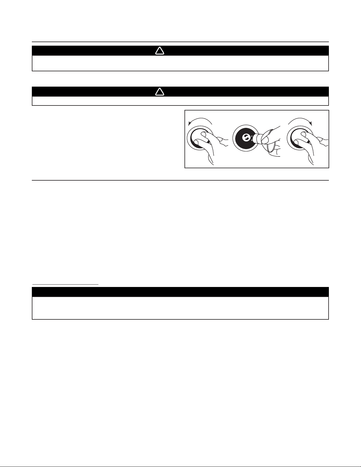
- 34 -
Riel de vertido de la grasa
El riel debe limpiarse con frecuencia. Sáquelo de la campana y límpielo con una disolución de detergente con agua. Lávelo
con mayor frecuencia si su tipo de cocina genera más grasa (alimentos fritos o cocina con wok). Deje que el riel seque
completamente antes de volver a instalarlo en la campana.
Limpieza del ventilador
Retire los filtros para tener acceso al ventilador. Limpie el ventilador con un aspirador. No lo sumerja en agua. Consulte el
manual de instrucciones del ventilador para mayor información.
Limpieza de la campana
Limpieza del acero inoxidable: Para que la campana siga teniendo un “ASPECTO BRILLANTE”:
Debe hacerse:
• Limpiar regularmente las superficies con un trapo limpio humedecido con una mezcla de agua templada y jabón suave
o detergente para la vajilla.
• Limpiar siempre en la dirección de las líneas originales de pulido del acero.
• Enjuagar siempre con agua limpia (2 o 3 veces) después de limpiar. Seque completamente.
• También puede utilizar un limpiador doméstico especial para acero inoxidable.
No debe hacerse:
• Utilizar un estropajo de acero o acero inoxidable u otro tipo de rasquetas para quitar la suciedad resistente.
• Utilizar limpiadores fuertes o abrasivos.
• Dejar que la suciedad se acumule.
• Dejar que el polvo del yeso u otros residuos de la construcción manchen la campana. Si efectúa obras de construcción
o renovación, cubra la campana para que no se manche la superficie de acero inoxidable.
Al escoger un detergente, evite:
• Los limpiadores que contienen blanqueador (lejía), ya que dañarán el acero inoxidable.
• Los productos que contengan cloruro, fluoruro, yoduro y bromuro, ya que deterioran las superficies rápidamente.
• Los productos combustibles que se emplean para la limpieza, como acetona, alcohol, éter, benzol, etc., ya que son
altamente explosivos y nunca deberían estar cerca de una cocina.
16. USO Y CUIDADO
Filtros
Los filtros deben limpiarse con frecuencia. Utilice una disolución de detergente con agua templada. Lávelos con mayor
frecuencia si su tipo de cocina genera más grasa (alimentos fritos o cocina con wok).
Retire los filtros empujándolos hacia la parte trasera de la campana y girándolos hacia abajo. Las placas de los filtros pueden
lavarse en el lavavajillas. Deje que los filtros sequen completamente antes de volver a instalarlos en la campana.
PRECAUCIÓN
Si la campana se instala en un lugar donde haya agua salada (p. ej., la costa), enjuague todas las
superficies una vez por semana con agua limpia (aunque no se haya usado la campana), y séquelas
completamente con un trapo.
15. SUSTITUCIÓN DE LAS BOMBILLAS
Esta campana debe utilizar bombillas halógenas protegidas de tipo MR16, de 120 V y 50 W con base GU10 o PAR16 con base
GU10 (incluidas).
ADVERTENCIA
Para prevenir el riesgo de lesiones corporales, no instale bombillas identificadas sólo para uso en
dispositivos encerrados.
!
ADVERTENCIA
Para prevenir el riesgo de lesiones corporales, deje que las bombillas halógenas se enfríen antes de quitarlas.
!
1. Para quitar las bombillas, empuje suavemente hacia arriba y
gire en sentido antihorario para liberar el casquillo de sus
ranuras.
NOTA: De ser necesario, utilice un guante de caucho para
lavar los platos para sujetar mejor la bombilla y sacarla.
2. Instale las bombillas nuevas colocando los casquillos de las
bombillas en sus ranuras, en los portalámparas.
3. Empuje suavemente hacia arriba y gire al mismo tiempo en
el sentido horario hasta que queden bien afianzadas.
12 3
HO0089
Page 35

17. FUNCIONAMIENTO
La campana funciona con tres mandos situados bajo el borde delantero de la campana.
1. Interruptor de las luces
2. Interruptor de encendido y apagado del ventilador
3. Control de la velocidad del ventilador
Interruptor de las luces
El interruptor de las luces permite encender y apagar las luces.
Utilice bombillas halógenas protegidas de tipo MR16, de 120 V y 50 W con base GU10 o PAR16 con base GU10 (incluidas).
Interruptor de encendido y apagado del ventilador
El ventilador funciona con dos mandos.
Utilice el interruptor de encendido y apagado para poner en marcha el ventilador a la velocidad que haya seleccionado con el
control de velocidad (número 3 de la ilustración).
El ventilador se enciende y se apaga con este interruptor.
Control de la velocidad del ventilador
Gire el botón de control de la velocidad en sentido antihorario para aumentar la velocidad del ventilador y en sentido horario
para disminuirla.
Termostato HEAT SENTRY
La campana viene equipada con un termostato HEAT SENTRY. Se trata de un dispositivo que acelera el ventilador cuando
detecta un calor excesivo sobre la superficie sobre la que se cocina.
Si el ventilador está ENCENDIDO en una velocidad baja, el termostato lo pondrá en la velocidad ALTA.
Cuando la temperatura baje a un nivel normal, el ventilador volverá a su velocidad original.
Uso de la campana con un asador de gas cubierto
Al abrir la tapa de su asador de gas puede que note una reducción en la captura del humo y del vapor.
GARANTÍA
GARANTÍA BROAN DE UN AÑO
Broan garantiza al comprador original de sus productos que éstos carecen de defectos en los materiales o de mano de obra
por un período de un año a partir de la fecha de compra original. NO EXISTEN OTRAS GARANTÍAS, EXPRESAS O
IMPLÍCITAS, INCLUYENDO —AUNQUE SIN LIMITARSE A ELLAS— LAS GARANTÍAS IMPLÍCITAS, DE APTITUD O
IDONEIDAD PARA UN PROPÓSITO PARTICULAR.
Durante el período de un año, y a su propio criterio, Broan reparará o reemplazará sin costo todo producto o pieza que se
considere defectuoso en condiciones normales de servicio y uso.
Esta garantía no cubre: a) el mantenimiento y servicios normales ni b) ningún producto o pieza mal utilizados o que hayan
sido objeto de negligencia, accidente, mantenimiento o reparación inadecuados (por compañías distintas a Broan),
instalación defectuosa, o instalación no conforme a las instrucciones de instalación recomendadas.
La duración de cualquier garantía implícita se limita a un periodo de un año, como se indica en la garantía expresa. Algunos
estados o provincias no permiten limitaciones en cuanto al tiempo de expiración de una garantía implícita, por lo que la
limitación antes mencionada puede que no se aplique en su caso.
LA OBLIGACIÓN DE BROAN DE REPARAR O REEMPLAZAR, CON ARREGLO A SU PROPIO CRITERIO, SERÁ EL
ÚNICO RECURSO LEGAL DEL COMPRADOR CONFORME A ESTA GARANTÍA. BROAN NO SE HACE
RESPONSABLE DE LOS DAÑOS ADICIONALES, CONSECUENTES O ESPECIALES QUE SURJAN O ESTÉN
RELACIONADOS CON EL USO O EL RENDIMIENTO DEL PRODUCTO. Algunos estados o provincias no permiten la
exclusión o limitación de daños adicionales o consecuentes, por lo que la limitación o exclusión antes
mencionada puede que no se aplique en su caso.
Esta garantía le proporciona derechos legales específicos, aunque usted también puede tener otros derechos, que varían
de un estado a otro, o de una provincia a otra. Cualquier modificación hecha en este producto sin la autorización de Broan
anulará esta garantía. Esta garantía reemplaza todas las garantías anteriores.
Para tener derecho al servicio de garantía, debe usted: a) Informar a Broan, en una de las direcciones o teléfonos que
aparecen abajo; b) Dar el número de modelo y el número de identificación de la pieza y c) Describir el tipo de defecto en el
producto o pieza. En el momento de solicitar un servicio cubierto por la garantía, deberá presentar una prueba de la fecha
de compra original.
Best by Broan®, P.O. Box 140, Hartford, WI 53027 USA (1-800-637-1453)
Best by Broan®, 550 Lemire Blvd., Drummondville, QC J2C 7W9 CANADA (1-866-737-7770)
HC0014
1
2 3
O
- 35 -
Page 36

PIEZAS
N . ° N . ° D E CTD (ANCHURA CAMPANA)
PIEZA DESCRIPCIÓN 42’’ 54’’
1 V03428 C
AMBIO DE SECCIÓN 9” X 18” X 10” REDONDO 11
2 V16765 C
ONJUNTO DE LA LÁMPARA GU-10 4 6
3 V05921 B
OMBILLAS HALÓGENAS (50 W, 120 V, PAR16, GU-10) 4 6
4 V06497 T
ERMOSTATO HEAT SENTRY 11
5 V06364 C
ONTROL GIRATORIO DE LA VELOCIDAD 11
6 V03504 B
OTÓN DE CONTROL DE LA VELOCIDAD DEL VENTILADOR 11
7 V06495 I
NTERRUPTOR DE LAS LUCES 11
8 V06496 I
NTERRUPTOR DEL VENTILADOR 11
9
V16939 F
ILTROS 8,95” x 8,61” X 1” 2 -
V16940 F
ILTROS 14,95” x 8,61” X 1” 1 3
10 V15432 C
LIP DEL FILTRO 33
11
V16958 R
IEL DE VERTIDO DE LA GRASA 36”, SS316 1 -
V16964 R
IEL DE VERTIDO DE LA GRASA 48”, SS316 - 1
12
V16996 E
STRUCTURA INTERIOR (42” X 24” X 18”) (INCLUYE EL ÍTEM 10) 1 -
V16997 E
STRUCTURA INTERIOR (54” X 24” X 18”) (INCLUYE EL ÍTEM 10) - 1
* V07697 G
UÍA DE INSTALACIÓN 11
B
OLSA CON PIEZAS (CONECTORES DE HILOS IMPERMEABLES (3),
* V04216
ABRAZADERAS DE HILOS LP16-AP (2), TORNILLOS N.°8 X 5/8’’ (8),
11
TORNILLOS N.°8 X3/8’’ (8), TORNILLOS DE CABEZA PLANA N.° 10 X 2’’ (4),
DISPOSITIVOS DE SUJECIÓN MURAL (2), ARANDELAS 3/16’’ DI X3/4’’ DE (2))
*V05869 L
OGOTIPO DE BEST BY BROAN 11
* V06933 C
ABLEADO ELÉCTRICO 11
*E
STE COMPONENTE NO SE MUESTRA.
MODELO
WPD29M
3
2
10
4
1
11
5
6
7
8
9
12
HL0085
 Loading...