

Page 1
7904 0117B
TEC HNICA L PARAME TER
CAUT ION
Befor e servi cing or c leani ng fan, s witch p ower of f at serv ice pan el. Loc k or tag se rvice p anel to
preve nt powe r from be ing swi tched o n accid ental ly.
Never u se chem icals t o clean t he fan.
Never s ubmer se the fa n motor o r other e lectr ical pa rts in wa ter.
Do not im merse p lasti c parts i n water o ver 60℃.
A. The gr ille, s crol l and blo wer whe el can be d ischa rged an d clean ed usi ng warm w ater or
kitc hen det ergen t.
B. Gent ly clea n fan, mo tor and i nteri or of hou sing wi th a dust ing bru sh.
MAI NTENA NCE
WD1 20NL
Ven til ati on Fa n Wit h Lig ht
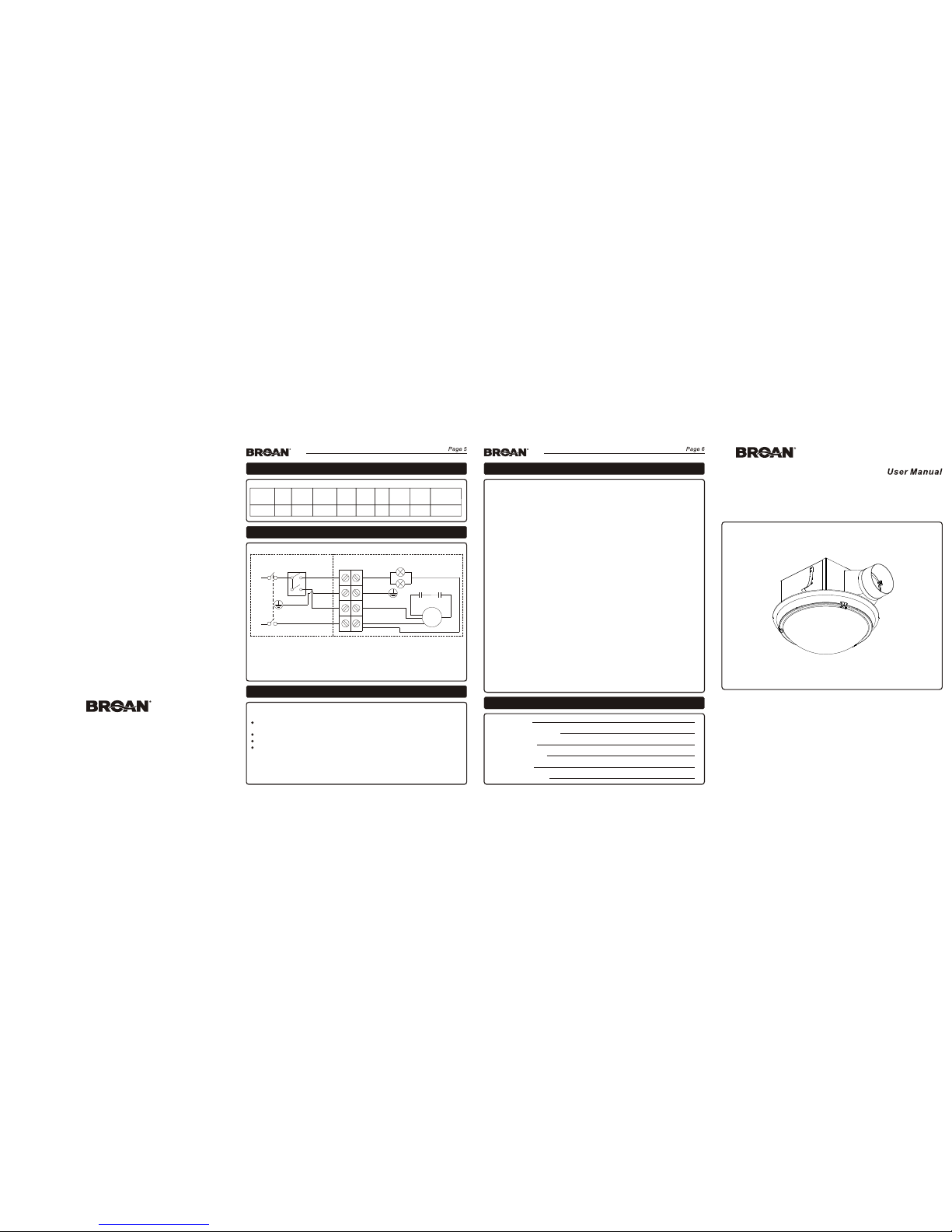
WIR ING DIA GRAM
2
4
/50 0
D1
2
0NL
W
1
1
0
36
6-1
2
2
2
x21
12
Ø
100
120
Mod l
e
2
5
Fan Powe r
(W)
x2×
4
2 M
a .
Light Po wer
(W)
Sound
(dB)
Room Siz e
2
(m )
Pressu re
(Pa)
Air Flow
3
(m /h )
Duct Siz e
(mm)
Ceilin g Openi ng
(mm)
Voltage
(V/Hz)
Inner C onnec tion
M
Blue
BrownBlack
Termina l Block
C1 C2
Brown
Yellow/ Green
Black
White
Black
L1(Fa n)
L2(Li ght)
Two Gang S witch
(Prov ided)
Outer C onnec tion
Power I nput 24 0V 50Hz
L
N
Black
http ://ww w.Broa n.com .au
Double P ole
Isolat ing Swi tch
(Not Pro vided )
WARR ANTY CA RD
WARR ANTY
Two Years Limited Warra nty:
Broan warran ts the original c onsumers' pur chase of its prod uct(s) that suc h product(s) wi ll be free from
defects in mat erials and work manship for a per iod of two years fr om the date of orig inal purchase .
During this tw o-year period , Broan will, at it s option, repai r or replace, wit hout charge, an y product or
part which is fo und to be defecti ve under normal u se and service.
THERE ARE NO OTHER WAR RANTIES, EXPR ESSED OR IMPLIE D, INCLUDING BU T NOT LIMITED
TO THE LABOR COST OF R EMOVING THE FAULTY PROD UCT(S), INSTALLI NG THE REPAIRED
OR REPLACED PR ODUCT(S), OR FO R TRANSPORTING TH E FAULTY PRODUCT(S) TO BRO AN
OR AN AUTHORIZED SERV ICE CENTRE.
This warrant y does not cover: ( a) countries ou tside of Australi a and New Zealand ( b) abnormal
maintenanc e and service (c) a ny products or pa rts which have be en subject to mis use, negligen ce,
natural disa sters or accide nts (out of Broan ’s control) impr oper maintena nce or repair (ot her than by
Broan or an Author ized Service Ce ntre) (d) fault y installatio n or installati on contrary to re commended
installati on instructio ns (e) any produc t(s) with a model n umber differen t from that being e xpressed in
the warranty c ard.
Claim Lodgem ent:
Please have yo ur original rec eipt, model and s erial number re ady for lodgeme nt of claim.
1. Call 1800 288 3 73. Warranty cla ims may be made wee kdays from 9am to 5 .30pm AEST, excluding
public holid ays.
2. Quote your mo del number and se rial number to ou r friendly staff .
3. Our staff wil l then provide yo u with a job number a nd assist you in you r claim.
4. You will be require d to email/post a c opy of your origi nal receipt for v erification .
The benefits c onferred by thi s warranty are in a ddition to all ri ghts and remedi es to a consumer un der
the Commonwe alth of Australia C ompetition an d Consumer Act 2010 o r other Commonw ealth or State
legislatio n and this warran ty does not purpo rt to limit or excl ude such rights a nd remedies.
Contact Info rmation:
Nortek Austral ia Pty Ltd. 2/11-21 Fo rge Street, Bla cktown, NSW, 2148 , Australia
Email: info@ nortekaustr alia.com.au Teleph one (+61) 1800 28 8 373
Custo mer Nam e:
Custo mer Con tact Tele phone :
Custo mer Addr ess:
Produ ct Mode l Numbe r:
Date of P urcha se:
Retai ler Inv oice Nu mber:
Page 2
REA D AND S AVE THESE I NSTRU CTION S
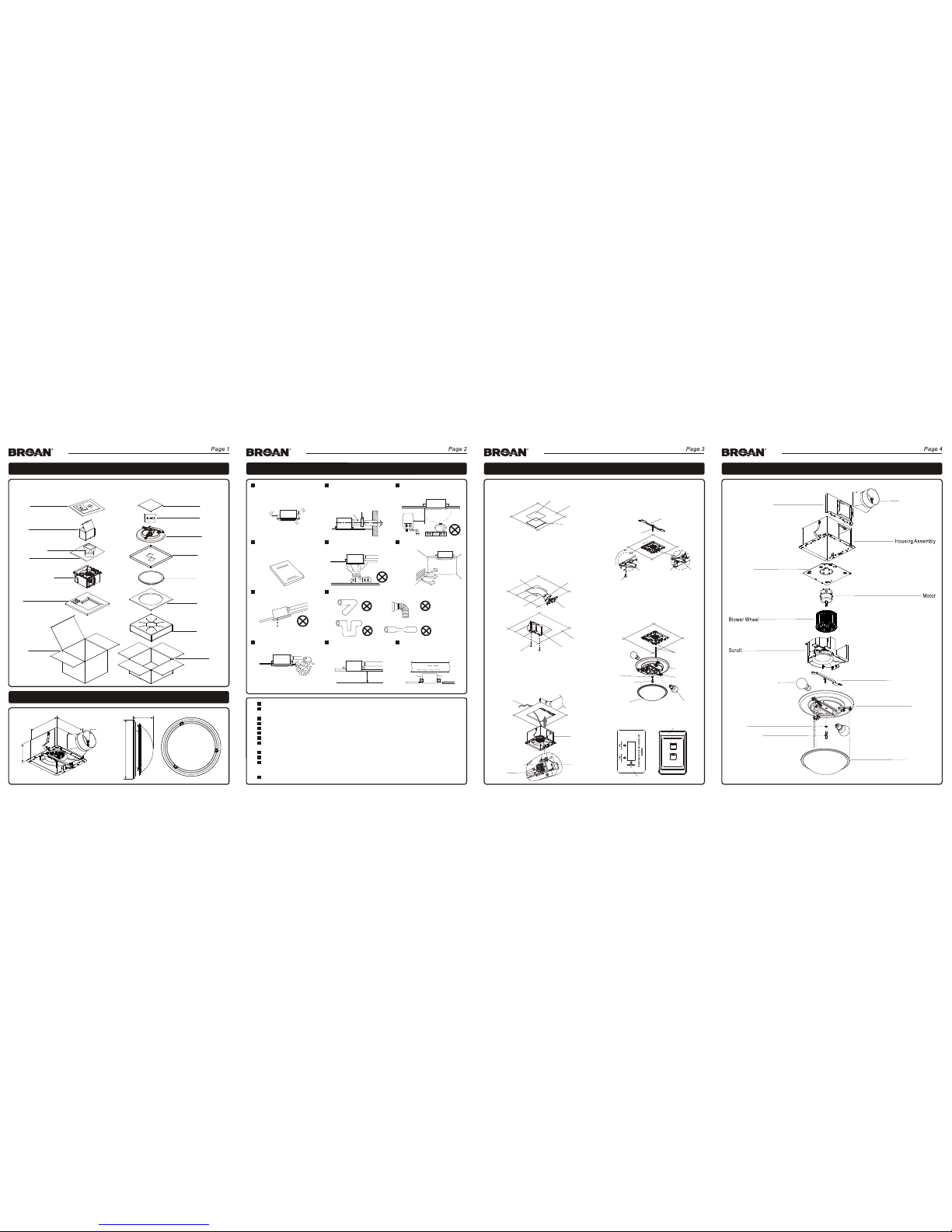
PRO DUCT ST RUCTU RE AND DIM ENSIO NS
PACK ING AND ACC ESSORY L IST
2 4
m0 m
4
20 mm
130mm
Ø100mm
Ø337m m
115mm
INS TALL THE PR ODUCT
Housi ng Assem bly
Duct Co nnect or
Glass S hade
PE Bag
Manua l, Pass C ard,
Screw s T4x20(2 pcs)
EPS
Access ory
Tube, Wa sherThrea ded
Carto n
Carto n
Glass f iller 2
Glass f iller 1
Light F ittin g
Fille r(2pc s)
Carto n
42W Hal ogen La mps(2 pcs),
Two Gang S witch
PE Bag
Light B ase
Glass Sha de
Halogen L amps(2p cs)
Washer
Motor P late
SER VICE PART S
Glass S hade
Washe r
Halog en Lamp s(2pc s)
Light F itting B racket
Duct Co nnect or
Conne cting B racke t
Produ ct pack ing lis t is show n below . Pleas e check w hen you o pen the c arton . If ther e is any
quest ions, p lease c ontac t the dis tribu tor or se rvice c enter.
5. Conne ct the light f itting el ectrica l cable wit h
the plug pr ovided. U sing the th readed tu be and
washer fi x the light b ase to the lig ht fittin g
bracke t. Instal l halogen la mps. Fin ally use
claws of li ght base to se cure the gl ass shade .
6. Conn ect wir e to rele vant fu ction s shown o n
the swi tch.
Two Gang S witch
FAN
LIGHT
Switc h Wirin g Diagr am
Threade d Tube
Light Bas e
Plug
Thread ed Tube
Light Ba se
claw (3p cs)
Cardb oard
1. .Use car dboard t empla te to mark t he corre ct
cut out s ize on the c eiling
2. Con nect t he flex ible d uct to th e duct
conn ector u sing t ape or t ies. En sure t he
flex ible d uct is in stal led as s traig ht as
poss ible. I nser t duct c onnec tor in to
conn ectin g brac ket an d fix to c eilin g usin g
scre ws (T4 x 2 0).
3. Remo ve the el ectri cal con necti on box co ver.
Inser t the cab les thr ough th e bush pr ovide d
and con nect as i ndica ted on th e wirin g
diagr am ensu ring th e cable s are cap tured
under t he term inal sc rew. Rep lace co ver.
Cut Out S ize: 21 2mmx2 12mm
Duct Co nnect or
Conne cting B racke t
Conne cting B racke t
Screw s T4x20 (2pc s)
Ceili ng
Flexi ble Du ct
Housi ng
Assem bly
Con nec t Pla ce
Push In
Cover
4. Fix the long sc rew (#10-24) t ightly onto the l ight
fitting bra cket. Clip bot h sides of the ligh t fitting
bracket und er slots in fan hou sing assembl y.
Use the short sc rew (#8-18) to fi x bracket
securely.
Light Fi tting Br acket
Long Scr ew #10-2 4
o
t
n
I
e
d
i
l
S
o
t
n
I
e
d
i
l
S
Light Fi tting Br acket
Short Scre w #8-18
Ceili ng
Cable s
Termina l Screw
Cable s
Slots
Cardbo ard
Instal lation wo rk must be
done by a qua lified pe rson
and inst alled secu rely.
Elect rical wi ring mus t be
done in ac corda nce with a ll
appli ance sta ndards .
Conve nient i nstal latio n and
servi ce
Inst all t his un it in a fl at
ceil ing o nly.
Preve nt wate r backf low.
Please kee p access openi ng.
Avoid t he foll owing c ases of d uct ins talla tion.
Provi de suct ion hol e(s).
The duct pi peline ve nted to
the outd oors must be
obliqu e, preven ting rain o r
frost ba ckflow.
Duct
In Room
Outdoor
Angle
Do not install in a plac e with
fumes and steam .
Hou sing a nd mo tor d oes n’t
tou ch oth er ce ili ng
str uctu re.
Preve nt vibr ation a nd nois e
Less than
Around temp eratu re
40℃ Above
50cm
The dis tance b etween f an
grill e and flo or must be
more th an 2.3 me ters.
Preve nt acci dent
>2.3m
Do not i nstal l in a pla ce wit h
high t emper atur e.
CAUTI ON
Do not use t o exhaus t hazar dous or e xplos ive mate rials .
When the p roduc t is conne cted to t he powe r using a sp ecial p ower ou tlet, th e plug an d power ou tlet mu st meet t he
requir ement s of AS3000 . The pow er outle t must be r ated at 10 a mps and e nsure a r eliabl e earth /grou nd conn ection .
Instal l the pro duct adj acent t o the pow er outle t.
Mount th e fan or fan /ligh t switc h to meet th e requi remen ts of AS30 00.
A damaged p ower cor d shoul d only be s ervic ed by a qual ified e lectr ician.
To avoid mot or beari ng dama ge and a no isy, unba lance d impell er, keep c onstr uctio n dust awa y from th ese par ts.
Childr en shou ld be supe rvise d to ensu re that th ey do not p lay wit h the appl iance .
The appl iance i s not inte nded fo r use by per sons (i nclud ing chi ldren) w ith red uced ph ysical , senso ry or men tal
capabi litie s, or lack o f exper ience a nd knowl edge, u nless t hey have b een giv en supe rvisi on or inst ructi on.
Do not imm erse th e produc t in wate r.
Ensure t hat the a pplian ce is swi tched o ff from th e suppl y mains al l-pol e disco nnecti on swit ch befo re repl ace the la mps.
An all-p ole dis connec tion sw itch sh all be mou nted be tween t he mains s upply a nd the wa ll switc h of the ap plian ce. The
all-po le disc onnect ion swi tch sha ll have a co ntact s epara tion in al l poles , provi ding fu ll disco nnect ion fro m the main s
supply.
The appl iance s hall, un der no ci rcums tances , be cove red wit h insula ting ma tting a nd simi lar mate rial.
 Loading...