

Page 1
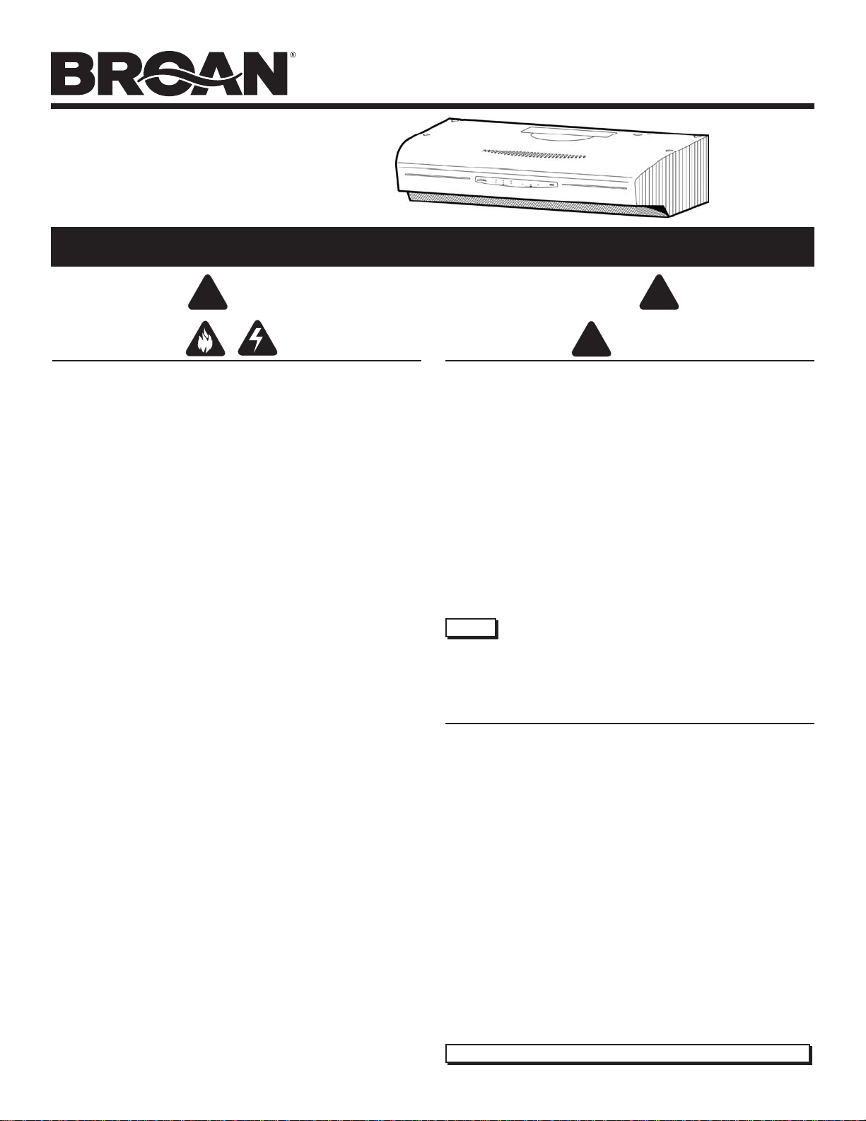
ALLURE
®
QS2 SERIES
RANGE HOOD
ALLURE
®
QS2 SERIES
RANGE HOOD
READ AND SAVE THESE INSTRUCTIONS
!
FOR DOMESTIC COOKING ONLY
WARNING
TO REDUCE THE RISK OF FIRE, ELECTRIC SHOCK, OR INJURY TO
PERSONS, OBSERVE THE FOLLOWING:
1. U s e this unit only in the manner intended by the manufacturer. If you have
questions, contact the manufacturer at the address or telephone number
listed in the warranty.
2. Before servicing or cleaning unit, switch power off at service panel and
lock the service disconnecting means to prevent power from being
switched on accidentally. When the service disconnecting means cannot
be locked, securely fasten a prominent warning device, such as a tag, to
the service panel.
3. Installation work and electrical wiring must be done by a qualified
person(s) in accordance with all applicable codes and standards, including fire-rated construction codes and standards.
4. Sufficient air is needed for proper combustion and exhausting of gases
through the flue (chimney) of fuel burning equipment to prevent backdrafting. Follow the heating equipment manufacturer’s guideline and safety
standards such as those published by the National Fire Protection Association (NFPA), and the American Society of Heating, Refrigeration and
Air Conditioning Engineers (ASHRAE), and the local code authorities.
5. When cutting or drilling into wall or ceiling, do not damage electrical wiring
and other hidden utilities.
6. To reduce the risk of fire or electric shock, do not use this range hood
with an additional speed control device.
7. Ducted
8. To reduce the risk of fire, use only metal ductwork.
9. Use with approved cord-connection kit only.
10. This unit must be grounded.
TO REDUCE THE RISK OF A RANGE TOP GREASE FIRE:
1. Never leave surface units unattended at high settings. Boilovers cause
2. Always turn hood ON when cooking at high heat or when cooking flaming
3. Clean ventilating fans frequently. Grease should not be allowed to
4. Use proper pan size. Always use cookware appropriate for the size of
TO REDUCE THE RISK OF INJURY TO PERSONS IN THE EVENT OF A
RANGE TOP GREASE FIRE, OBSERVE THE FOLLOWING:*
1. SMOTHER FLAMES with a close-fitting lid, cookie sheet, or metal tray,
2. NEVER PICK UP A FLAMING PAN — You may be burned.
3. DO NOT USE WATER, including wet dishcloths or towels - violent steam
4. Use an extinguisher ONLY if:
fans must always
smoking and greasy spillovers that may ignite. Heat oils slowly on low or
medium settings.
foods.
accumulate on fan or filter.
the surface element.
then turn off the burner. BE CAREFUL TO PREVENT BURNS. If the
flames do not go out immediately, EVACUATE AND CALL THE FIRE
DEPARTMENT.
explosion will result.
A. You know you have a Class ABC extinguisher and you already know
how to operate it.
B. The fire is small and contained in the area where it started.
C. The fire department is being called.
D. You can fight the fire with your
* Based on “Kitchen Fire Safety Tips” published by NFPA.
be vented to the outdoors.
back to
an exit.
Page 1
Patent No.:
US D450, 829 S
!
CAUTION
1. For indoor use only.
2. For general ventilating use only. Do not use to exhaust hazardous or
explosive materials and vapors.
3. To avoid motor bearing damage and noisy and/or unbalanced impellers,
keep drywall spray, construction dust, etc. off power unit.
4. For best capture of cooking impurities, your range hood should be
mounted so that the top of the hood is 24-30” above the cooking surface.
5. Please read specification label on product for further information and
requirements.
Installer: Leave this manual with
the homeowner.
Homeowner: Operating and
Cleaning information on page 6.
NOTE If hood is to be installed Non-Ducted:
Purchase a set of (2) non-ducted filters from your
local distributor or retailer and attach them to the
aluminum mesh filters.
TABLE OF CONTENTS
This manual is divided into sections as follows:
“PREPARE HOOD LOCATION”
Run ductwork from roof or wall cap, and electrical wiring from service
panel - to installation location
“PREPARE THE HOOD”
Get your hood ready for installation
“CONNECT WIRING”
Make electrical wiring connections to hood
“INSTALL HOOD”
Secure hood to cabinet and ductwork - install bulbs and filters
“OPERATION”
How to use the hood controls
“CLEANING”
Keep your hood in top working condition
“SERVICE PARTS”
Part numbers and exploded view of hood components
“WARRANTY”
One-year limited warranty and how to contact us
Register your product online at: www.broan.com/register
!
Page 2
ALLURE
®
QS2 SERIES
RANGE HOOD
Page 2
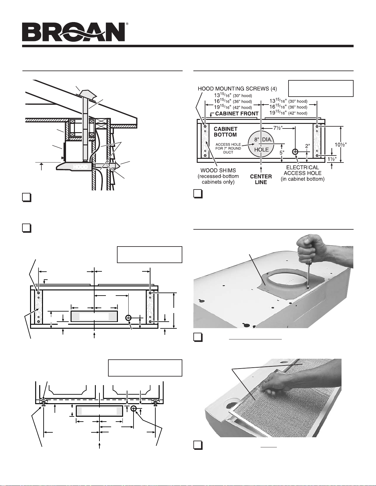
PREPARE HOOD LOCATION
ROOF CAP
SOFFIT
CABINET
HOODHOOD
24" - 30" ABOVE
COOKING SURFACE
1 Determine whether hood will discharge vertically (3¼” x 10”
or 7” Round), or horizontally (3¼” x 10” only). For vertical or
horizontal discharge, run ductwork between the hood location
and a roof cap or wall cap. For best results, use a minimum
number of transitons and elbows.
2 Use diagrams, below, for proper placement of ductwork and
electrical cutout in cabinet or wall. For a non-ducted installation, DO NOT cut a duct access hole.
HOOD MOUNTING SCREWS (4)
13
16
19
15
15
15
/
"
16
/
"
16
/
"
16
(30" hood)
(36" hood)
(42" hood)
CABINET FRONT
3¼" X 10" or
7" ROUND DUCT
(For vertical
discharge)
HOUSE WIRING
(Top or Back of hood)
3¼" X 10" DUCT
(For horizontal discharge)
VERTICAL DUCTING
15
/
13
"
(30" hood)
16
15
/
16
"
(36" hood)
16
15
/
"
(42" hood)
16
19
WALL CAP
3¼” X 10”
PREPARE HOOD LOCATION
7” ROUND
VERTICAL DUCTING
3 Run house wiring between service panel and hood location.
PREPARE THE HOOD
7” ROUND
DUCT PLATE
5"
1¼"
WOOD SHIMS
(recessed-bottom
cabinets only)
WOOD SHIMS
(recessed-bottom
cabinets only)
3¾"
CABINET
BOTTOM
15
13
/
16
15
16
/
16
15
19
/
16
HOOD
MOUNTING
SCREWS (4)
7½"
CABINET BOTTOM
5¼"
VERTICAL DUCT
ACCESS HOLE
5¼"
CENTER
LINE
HORIZONTAL DUCTING
CABINET FRONT
HORIZONTAL DUCT
ACCESS HOLE
5¼"
13
16
19
LINE
"
(30" hood)
"
(36" hood)
"
(42" hood)
5¼"
CENTER
2"
ELECTRICAL
ACCESS HOLE
(in cabinet bottom)
3¼” X 10”
1
"
/
¾"
8
7½"
15
"
(30" hood)
/
16
15
"
(36" hood)
/
16
15
"
(42" hood)
/
16
ELECTRICAL
ACCESS HOLE
(in wall)
10½"
1½"
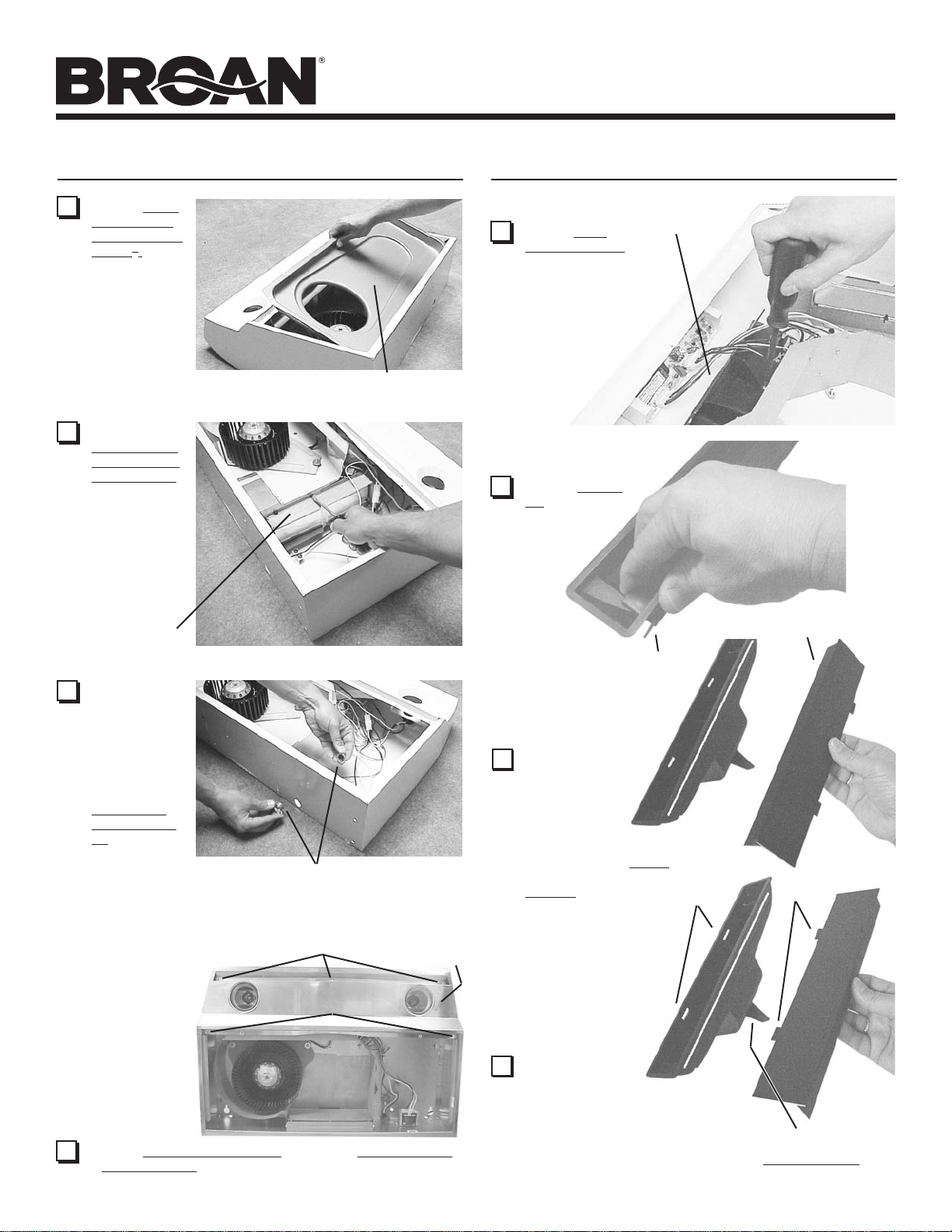
1 Remove 7” Round Duct Plate from top of hood. Set duct
plate aside - with mounting screws.
FILTERS
2 Remove tape holding Filters in place. Pull down on filter
tabs or finger holes and lift filters out. Set filters aside.
Page 3
ALLURE
PREPARE THE HOOD PREPARE THE HOOD
®
QS2 SERIES
RANGE HOOD
Page 3
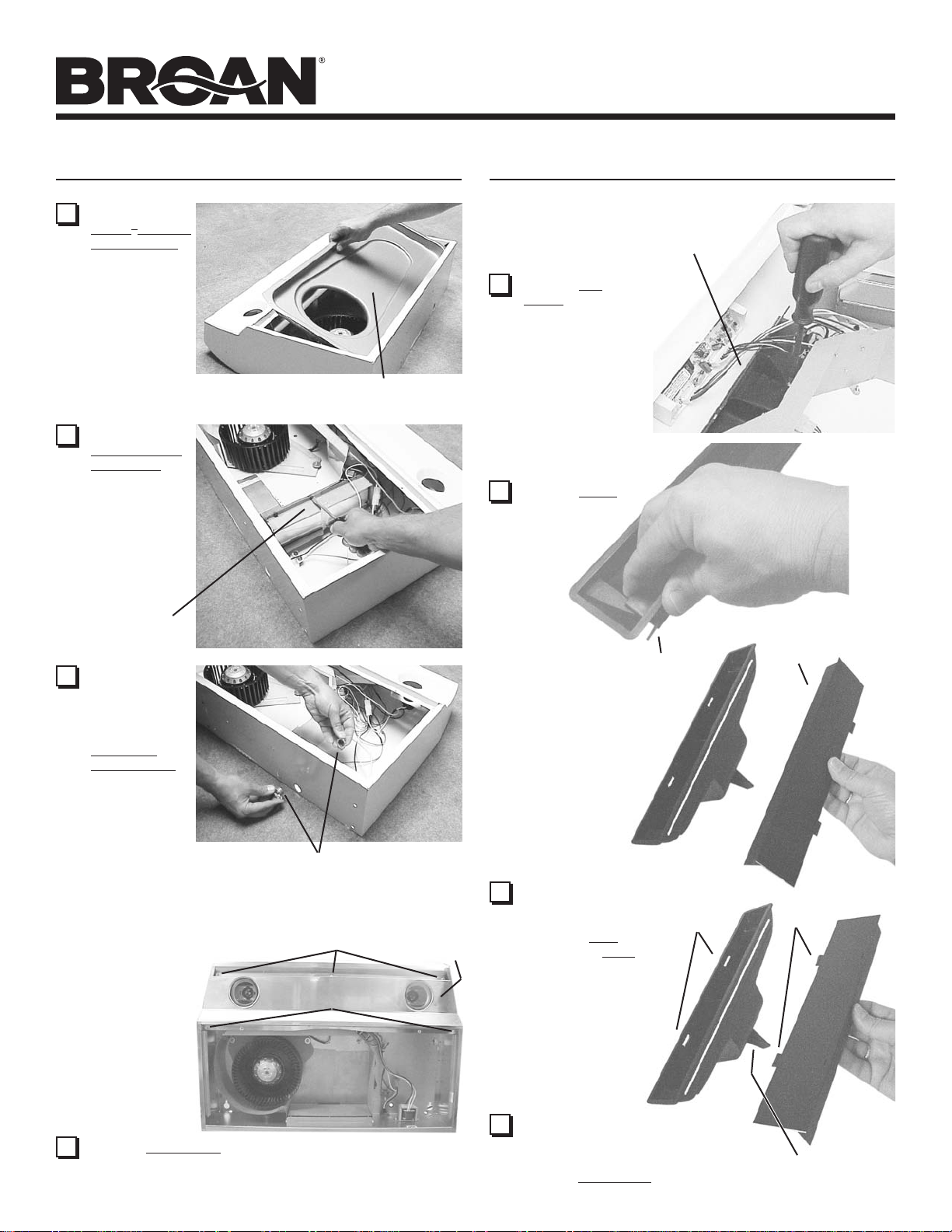
3 Remove
Teflon® is a registered
trademark of DuPont.
4 Remove
5 Remove either
®
Teflon
bottom cover
from hood.
Set cover and
mounting screws
aside.
Damper/Duct
Connector
from inside
the hood. Set
connector
aside - with
mounting
screws and
parts bag.
top or back
wiring knockout and install
approved
Electrical
Cable Clamp.
-coated
DAMPER/
DUCT
CONNECTOR
TEFLON®-COATED BOTTOM COVER
(Held in place with 2 screws)
7 Remove Air
Chute - held in
place with one
(1) screw.
NOTE: Be care-
ful not to disconnect any wires.
8 Remove Baffle
from air chute.
AIR CHUTE
BAFFLE
BAFFLE
ELECTRICAL CABLE CLAMP
Non-Ducted Installation - Skip to Step 15.
The following
(3) #8 SCREWS
Steps (6 thru
14) are for
DUCTED
(2) #8 SCREWS
INSTALLATION
ONLY.
6 Remove Light Panel - held in place with (3) #8 screws
and (2) #8 screws. Disconnect light assembly wire harness
(white connector).
LIGHT
PANEL
9 Rotate baffle. Re-
insert baffle into air
chute (as shown) so
that baffle tabs fit all
the way into slots in
air chute. An audible
“click” will be heard
when fully installed.
This will close off
the air flow through
the non-ducted slots
on top of hood.
10
Re-install air chute, re-connect wire
harness, and replace light panel.
NOTE: Be careful not to trap wires
between support fin and light panel.
SLOTS
TABS
SUPPORT FIN
Page 4
ALLURE
®
QS2 SERIES
RANGE HOOD
Page 4
PREPARE THE HOOD
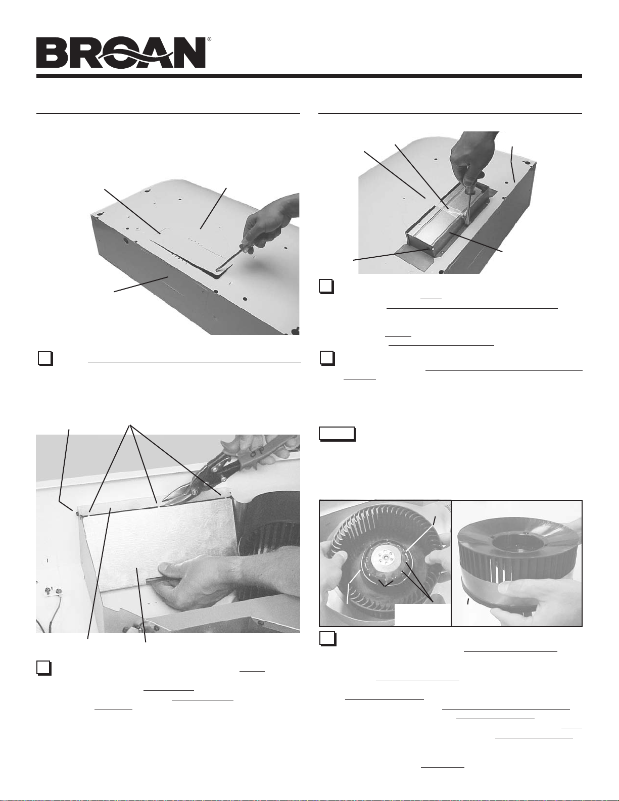
TOP RECTANGULAR
DUCT KNOCKOUT
(Remove for 3¼” x 10”
Vertical & for 7” Round
Discharge)
REAR
RECTANGULAR
DUCT KNOCKOUT
(Remove for 3¼” x 10”
Horizontal Discharge)
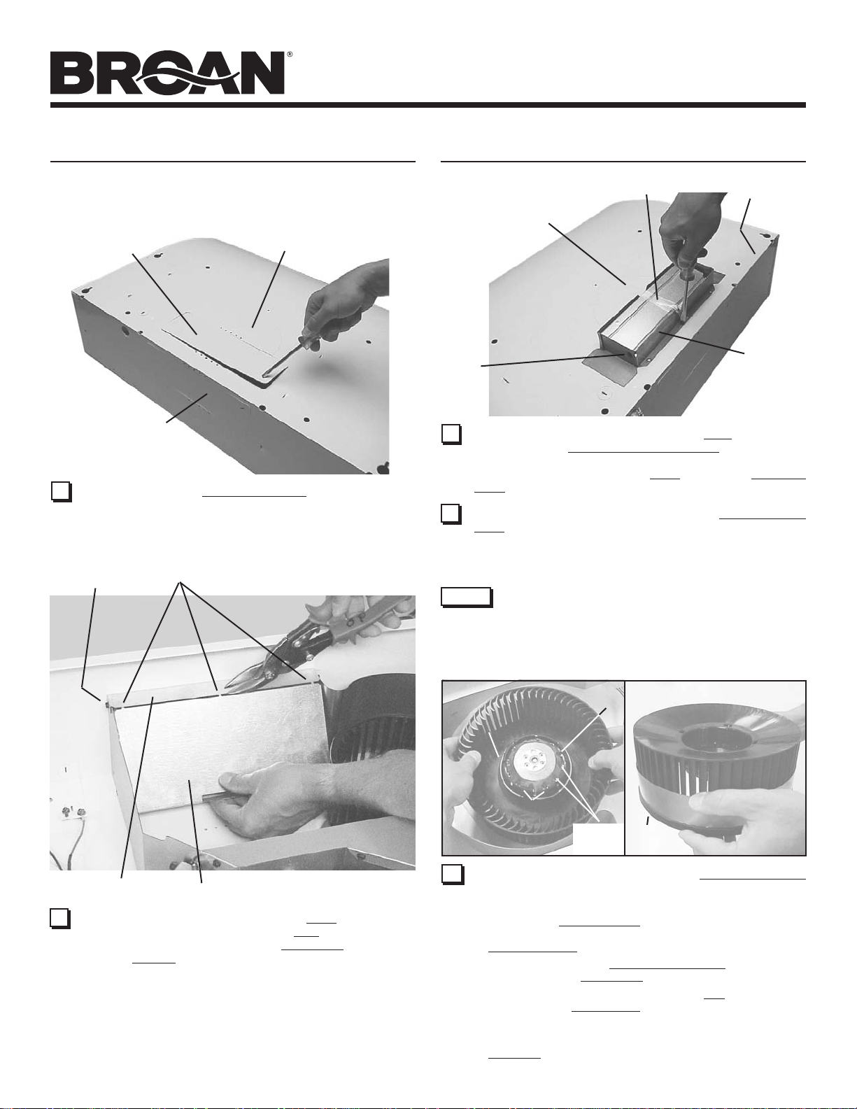
11 Remove appropriate Duct Knockout(s) from top or back of
hood.
SCREW
TIES
SEMI-CIRCULAR
DUCT KNOCKOUT
(Remove for 7” Round
Discharge)
PREPARE THE HOOD
TOP/BACK
EDGE
DAMPER/
DUCT
CONNECTOR
(Vertical discharge
position shown)
TAPE
UP TO 1”
SIDE-TO-SIDE
ADJUSTMENT
PIVOT
13 3¼” x 10” Ducted Discharge Only: Remove Tape from damper
flap and attach Damper/Duct Connector over knockout
opening with screws removed in Step 4 under “PREPARE
THE HOOD”. Make sure damper Pivot is nearest to Top/Back
Edge of hood.
14 7” Round Ducted Discharge Only: Re-install 7” Round Duct
Plate removed in Step #1 under “PREPARE THE HOOD”.
Install a 7” round damper (purchase separately). Damper
flap must open freely in direction of airflow (away from range
hood).
NOTE
up to ½” on either side of hood center. In extreme off-center
installations, one end of the duct connector may need to be trimmed
to clear the electrical cable clamp.
To accomodate off-center ductwork, the Damper/Duct
Connector can be installed up to 1-inch on either side of
hood center or the 7” Round Duct Plate can be installed
METAL STRIP
12 Horizontal Discharge Only: Remove the Plate in front of the
horizontal discharge knockout. Cut the Ties, lift plate out, and
discard plate. DO NOT REMOVE the Metal Strip held in place
with two Screws.
PLATE
RETAINING
RING
15 Non-Ducted Installations Only: Require a Performance Ring
to be attached to the blower wheel.
To install ring:
1. Remove the Blower Wheel by rocking it side to side and
applying a slight force to pull wheel from motor. Remove
Retaining Ring if necessary.
2. Slide the ring onto the Small Diameter End of the wheel
and down to the Stop Edge of the wheel.
3. Reassemble wheel to motor. Make sure Tab on wheel fits
into one of the Motor Slots.
4. Push wheel down until it is locked in place.
5. Check that wheel is properly positioned as shown. Press
Sections into place if necessary. Make sure wheel turns
freely.
BLOWER
WHEEL
SECTIONS
TAB
MOTOR
SLOTS
SMALL DIAMETER
END
RING
STOP
EDGE
Page 5
ALLURE
®
QS2 SERIES
RANGE HOOD
Page 5
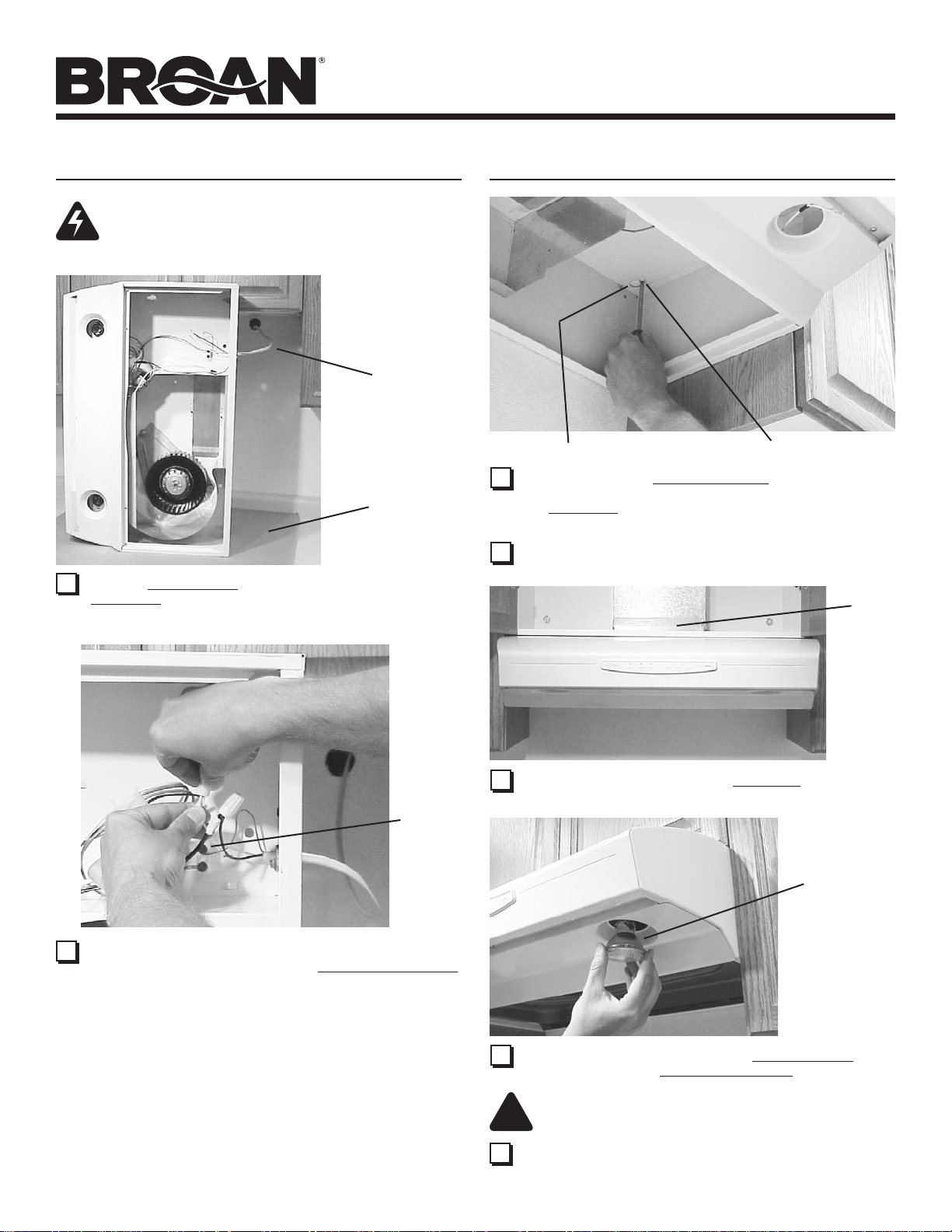
CONNECT WIRING
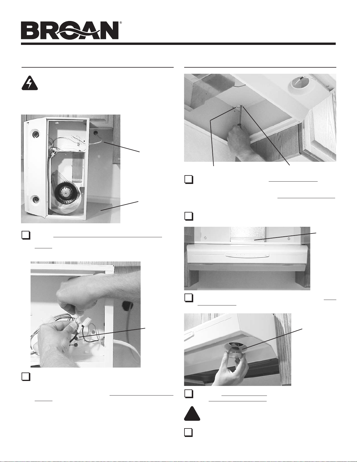
WARNING: To reduce the risk of electric shock,
make sure power is switched off at the service
panel. Lock or tag service panel to prevent power
from being switched on accidentally.
HOUSE
WIRING
(120 VAC)
CARDBOARD
(Use to protect
cooktop)
1 Connect House Wiring (120 VAC) to hood. Use a piece of
Cardboard to protect the cooktop, if necessary.
INSTALL HOOD
KEYHOLE (4)
1 Hang hood from (4) Mounting Screws. Slide hood towards
wall until mounting screws are engaged in narrow end of
(4) Keyholes. Tighten mounting screws securely. A long
screwdriver works best.
2 Replace bottom cover.
MOUNTING SCREW (4)
DUCT
TAPE
GREEN
GROUND
SCREW
2 Connect house black to hood black wire, house white to hood
white wire, and house ground under Green Ground Screw.
Securely tighten cable clamp onto house wiring.
3 Connect ductwork to hood. Use Duct Tape to make joints
secure and air tight.
PAR20,
50W MAX.
HALOGEN
BULB (2)
- or R16,
40W MAX.
INCANDESCENT
BULB (2)
4 Install (2) PAR20, 50 W Maximum Halogen Bulbs or (2)
R16, 40 W Maximum Incandescent Bulbs. Purchase bulbs
separately.
CAUTION: Bulbs may be hot! Refer to bulb packaging
!
for further information.
5 Replace filters, turn on power at service panel, and test for
proper operation.
Page 6
ALLURE
®
QS2 SERIES
RANGE HOOD
Page 6
NON-DUCTED FILTERS
If hood is to be installed Non-Ducted:
Purchase a set of (2) Non-Ducted Filters from your local
distributor or retailer and attach them to the aluminum mesh
filters.
NOTE: For models that are installed in the non-ducted mode,
the most effective operation is achieved at speeds 1 and
2. These speeds provide the most efficient and quiet
operation during cooking, while maximizing the benefits
of the recirculating filtration system.
OPERATION
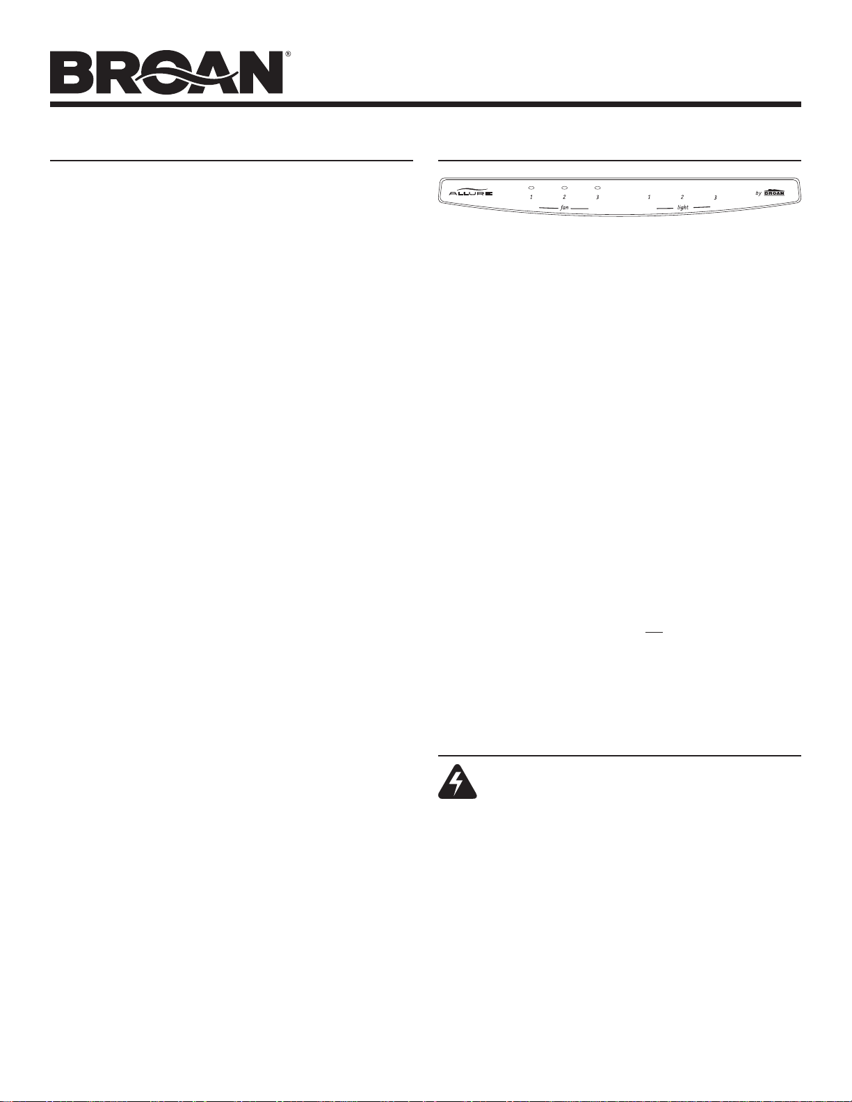
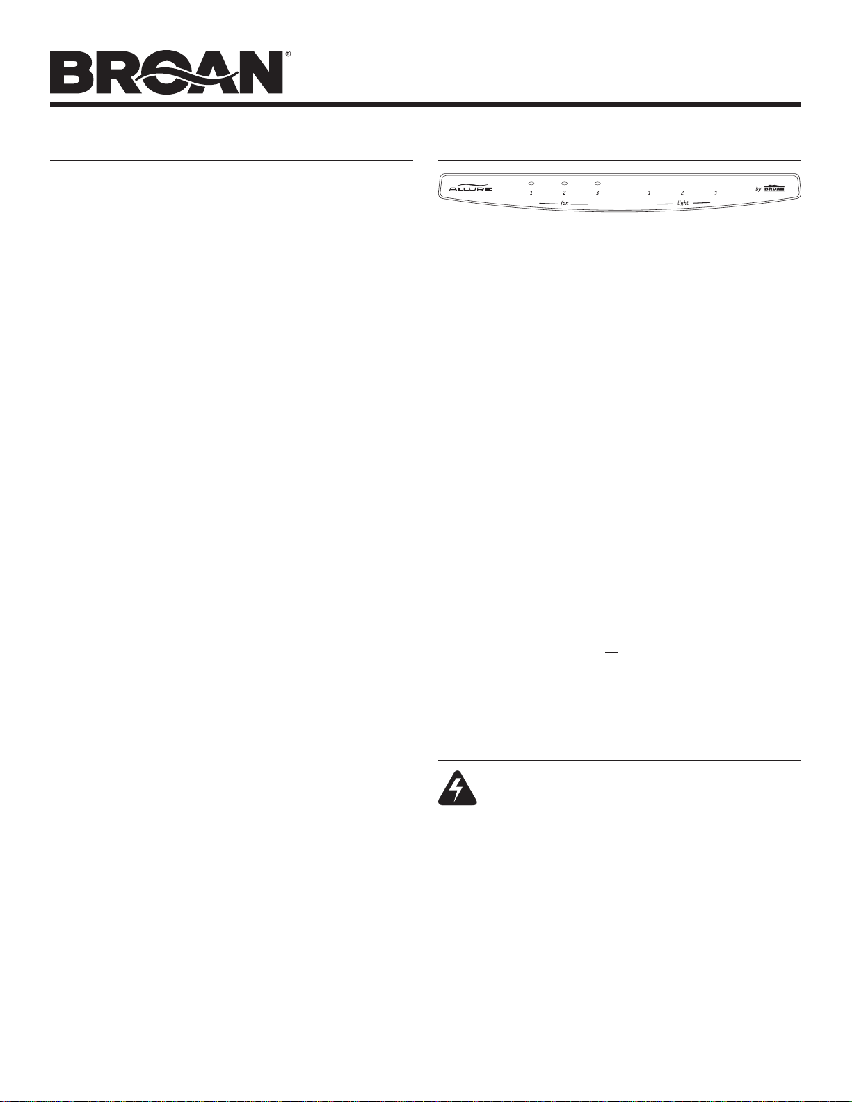
Fan and Lights: 3 push button switches for each. Push any but-
ton to select one of 3 fan speeds or one of 3 light levels. Push the
same button to turn fan or light off. Press another button to change
fan speed or light level. A light above each fan button indicates the
fan speed.
Heat Sentry: Your range hood is equipped with the Heat Sentry
feature, which monitors temperature. The Heat Sentry will automatically turn the fan on at its highest speed when the temperature is
above normal.
1) If a fan setting is selected when the Heat Sentry in on, the light
above the fan button will flash on and off.
2) If the fan setting is off when the Heat Sentry is on, the light above
fan button 3 will flash on and off rapidly.
After the temperature has lowered to normal, the fan will change to
the setting prior to the Heat Sentry turning on.
Fuse: The hood control contains a fuse to protect it from power
surges. If the fuse has opened (blown), the green fan-level indicators
will operate properly when the fan buttons/switches are pressed - but
the fan and lights will not turn on.
mm, 10 Amp, Fast-Acting, 125V (min.). Common
The fuse is a 5 x
manufacturer and part numbers are: Littlefuse, 217010; Bussmann,
GMA10A; Wickmann, 1942100. Radio Shack, Digikey (1-800-344-
4539), and most electronic supply stores have them in stock.
To replace the fuse:
1. Disconnect power at service entrance.
2. Remove filters, bottom panel, light wire harness, and air chute.
3. Remove and inspect fuse. If it is not open (blown), additional
diagnostics need to be done.
4. Install new fuse.
5. Re-assemble air chute, light wire harness, bottom panel, and
filters.
6. Turn on power and check hood/control operation.
20
CLEANING
WARNING: To reduce the risk of electric shock, disconnect from power supply before cleaning.
Aluminum mesh filters: Clean frequently using hot water and a
mild detergent. Filters are dishwasher safe.
Charcoal filters: Clean filter surfaces frequently with a damp cloth
and a mild detergent. DO NOT immerse filters in water or put in
dishwasher. The special “Clean Sense” feature indicates when the
filter is to be replaced. The blue and yellow strips will blend to green
when it is time to change the filter. The “Clean Sense” feature works
best when facing toward the cooking surface.
To clean hood: Remove filters. Use a damp cloth and a mild detergent to wipe all grease-laden surfaces. Do not use abrasive cloth,
steel wool pads, or scouring powder on the Teflon
cover or on any painted surface. Use care when cleaning blower
wheel - it must not become bent or misaligned. DO NOT ALLOW
WATER TO ENTER MOTOR. Make sure all surfaces are completely
dry before re-installing filters and restoring power.
Motor is permanently lubricated. Do not oil or disassemble motor.
®
is a registered trademark of DuPont.
Teflon
®
-coated bottom
Page 7

ALLURE
®
QS2 SERIES
RANGE HOOD
Page 7
SERVICE PARTS
KEY NO. PART NO. DESCRIPTION
1 R680508 7” Round Duct Plate (includes hardware)
2 R740013 Damper/Duct Connector (includes hardware)
3 R602017 Screw, #8-18 x ¼ Hex* (2 in package)
4 R334755 Motor Capacitor (includes wire nuts & hardware)
5 R501031 Isolation Transformer
6 R627501 Nameplate, White
R627502 Nameplate, Almond
R627503 Nameplate, Black
R627528 Nameplate, Biscuit
7 R169005 Control Panel, White (includes Key No. 6 & hardware)
R169006 Control Panel, Almond (includes Key No. 6 & hardware)
R169007 Control Panel, Black (includes Key No. 6 & hardware)
R169008 Control Panel, Biscuit (includes Key No. 6 & hardware)
8 R601535 Screw for Plastic, #6 x ½ Flat Hd. (3 in package)
9 R602534 Screw, #8-18 x 3/8 (2 in package)
10 R602533 Ground Screw
11 R680505 Scroll Cover, Outlet (includes hardware)
12 R680507 Scroll Cover, Front (includes hardware)
13 R111663 Control Assembly (includes Key Nos. 6, 7 & hardware)
14 R401647 Air Chute Assembly (includes Key No. 15 & hardware)
15 R401646 Baffle
16 R601536 Screw, Metric M4 x 6mm (4 in package)
17 R651973 Motor Plate (Includes Key No. 18)
18 R169009 Motor Plate Mounting Kit (3 of each part)
19 R520132 Motor (includes Key No. 16)
20 R531068 Blower Wheel (Includes Key No. 21)
21 R607215 Retaining Ring
22 R111630 Lamp Socket Assembly
23 R7201731 Light Panel, 30 in. White
R7201751 Light Panel, 36 in. White
R7201771 Light Panel, 42 in. White
R7201732 Light Panel, 30 in. Almond
R7201752 Light Panel, 36 in. Almond
R7201772 Light Panel, 42 in. Almond
R7201734 Light Panel, 30 in. Black
R7201754 Light Panel, 36 in. Black
R7201774 Light Panel, 42 in. Black
R7201735 Light Panel, 30 in. Biscuit
R7201755 Light Panel, 36 in. Biscuit
R7201775 Light Panel, 42 in.
R720174 Light Panel, 30 in. Stainless
R720176 Light Panel, 36 in. Stainless
R720178 Light Panel, 42 in. Stainless
24 R607660 Hole Plug (1 req.)
25 * Pop Rivet, .125D (3 req.)
26 R169016 Filter Spring Kit
27 R680511 Bottom Cover, 30 in. (includes Key Nos. 9, 25, & 26)
R680520 Bottom Cover, 36 in. (includes Key Nos. 9, 25, & 26)
R680527 Bottom Cover, 42 in. (includes Key Nos. 9, 25, & 26)
28 R501034 Autotransformer (includes hardware)
29 99010302 Aluminum Mesh Filter, 30 in. (2 in package)
99010303 Aluminum Mesh Filter, 36 in. (2 in package)
99010304 Aluminum Mesh Filter, 42 in. (2 in package)
30 R730111 Non-Ducted Blower Wheet Assembly
(includes Key Nos. 20 & 21)
** 99010308 Non-ducted Filter Kit, 30 in.
** 99010309 Non-ducted Filter Kit, 36 in.
** 99010310 Non-ducted Filter Kit, 42 in.
** R111627 Wire Harness
** R564074 Control Fuse, 10-Amp
Order replacement parts by PART NO. - not by KEY NO.
* Standard hardware - may be purchased locally.
** Not illustrated - purchase separately.
Biscuit
15
14
7
13
16
17
19
3
6
24
8
1
3
12
23
9
18
27
20
21
Replacement parts
can now be ordered
on our website.
Please visit us at
www.Broan.com
30
3
4
3
5
11
2
9
10
28
22
9
9
9
26
29
Page 8
®
ALLURE
QS2 SERIES
RANGE HOOD
Page 8
WARRANTY
BROAN-NUTONE ONE YEAR LIMITED WARRANTY
Broan-NuTone warrants to the original consumer purchaser of its products that such products will be free from defects in materials or
workmanship for a period of one year from the date of original purchase. THERE ARE NO OTHER WARRANTIES, EXPRESS OR IMPLIED,
INCLUDING, BUT NOT LIMITED TO, IMPLIED WARRANTIES OF MERCHANTABILITY OR FITNESS FOR A PARTICULAR PURPOSE.
During this one-year period, Broan-NuTone will, at its option, repair or replace, without charge, any product or part which is found to be
defective under normal use and service.
THIS WARRANTY DOES NOT EXTEND TO FLUORESCENT LAMP STARTERS AND TUBES. This warranty does not cover (a) normal
maintenance and service or (b) any products or parts which have been subject to misuse, negligence, accident, improper maintenance
or repair (other than by Broan-NuTone), faulty installation or installation contrary to recommended installation instructions.
The duration of an implied warranty is limited to the one-year period as specified for the express warranty. Some states do not allow
limitation on how long an implied warranty lasts, so the above limitation may not apply to you.
BROAN-NUTONE’S OBLIGATION TO REPAIR OR REPLACE, AT BROAN-NUTONE’S OPTION, SHALL BE THE PURCHASER’S SOLE
AND EXCLUSIVE REMEDY UNDER THIS WARRANTY.
TIAL OR SPECIAL DAMAGES ARISING OUT OF OR IN CONNECTION WITH PRODUCT USE OR PERFORMANCE. Some states do
not allow the exclusion or limitation of incidental or consequential damages, so the above limitation may not apply to you.
This warranty gives you specific legal rights, and you may also have other rights, which vary from state to state. This warranty supersedes
all prior warranties.
To qualify for warranty service, you must (a) notify Broan-NuTone at the address or telephone number below, (b) give the model number
and part identification and (c) describe the nature of any defect in the product or part. At the time of requesting warranty service, you
must present evidence of the original purchase date.
Broan-NuTone LLC Hartford, Wisconsin www.broan.com 800-558-1711
BR
OAN-NUTONE SHALL NOT BE LIABLE FOR INCIDENTAL, CONSEQUEN-
626978D
Page 9

CAMPANA
®
ALLURE
CAMPANA EXTRACTORA
SERIE QS2 ALLURE
QS2 SERIES
RANGE HOOD
Página 9
Page 9
®
EXTRACTORA
SERIE QS2 ALLURE
®
LEA Y CONSERVE ESTAS INSTRUCCIONES
!
ADVERTENCIA
PARA REDUCIR EL RIESGO DE INCENDIO, CHOQUE ELECTRICO, O
LESION A PERSONAS, PROCURE LO SIGUIENTE:
1. Utilice esta unidad sólo en la manera prescrita por el fabricante. Si tiene
usted alguna pregunta, comuníquese con el fabricante a la dirección o
el teléfono indicados en la garantía.
2. Antes de efectuar algún servicio o limpieza, se debe desconectar la
corriente eléctrica en el armario de circuitos y asegurarlo con llave para
evitar que la corriente sea conectada accidentalmente. Cuando no se
puedan inmovilizar los medios de desconexión de servicio, pegue con
seguridad un dispositivo de advertencia prominente, tal como una etiqueta, en el tablero de servicio.
3. Todo trabajo de instalación y cableado eléctrico debe ser realizado por
personal calificado y de acuerdo con todos los códigos y normas pertinentes, incluyendo los códigos y normas relacionados con construcción
clasificada para incendio.
4. Aire suficiente es necesario para facilitar la combustión adecuada y la
salida apropiada de gases por la chimenea de la unidad y para evitar corrientes de aire invertidas. Siga las instrucciones y medidas de seguridad
del fabricante del equipo y de las sociedades profesionales de equipos
de calentadores y los reglamentos de seguridad locales.
5. A cortar o perforar la pared o el techo, no dañe el cableado eléctrico u
otros servicios públicos ocultos a la vista.
6. Para reducir el riesgo de incendio o de descarga eléctrica, no utilice este
ventilador con ningún dispositivo de una control de velocidad de estado
sólido adicional.
7. Los abanicos con ducto deberán siempre tener una salida hacia el
exterior.
8. Para reducir el riesgo de incendio, use sólo ductos de metal.
9. Uso con el kit aprobado del la conexión de la cuerda solamente.
10. Esta unidad se debe instalar con tierra efectiva.
PARA REDUCIR EL RIESGO DE INCENDIO DEBIDO A GRASA ACUMULADA EN LAS HORNILLAS:
1. Nunca deje sin atender las unidades de superficie cuando tengan ajustes
altos. Los reboses pueden provocar humo y derrames grasosos que
se pueden incendiar. Caliente lentamente el aceite en un ajuste bajo o
medio.
2. Siempre ENCIENDA la campana cuando cocine con alta temperatura o
cuando cocine alimentos que se puedan incendiar.
3. Limpie con frecuencia los ventiladores. No debe permitir que la grasa se
acumule en el ventilador ni en el filtro.
4. Utilice un sartén de tamaño adecuado. Siempre utilice el utensilio ade-
cuado al tamaño del elemento de superficie.
PARA REDUCIR EL RIESGO DE LESION A PERSONAS RESULTADO DE
UN INCENDIO DEBIDO A GRASA ACUMULADA EN LAS HORNILLAS,
PROCURE LO SIGUIENTE:*
1. AHOGUE LAS LLAMAS con una tapa ajustada o charola de metal,
después apague la hornilla. TENGA CUIDADO A FIN DE EVITAR QUEMADURAS. Si las llamas no se apagan de inmediato, EVACUE Y AVISE
A LOS BOMBEROS.
2. NO LEVANTE NUNCA UNA SARTEN QUE ESTE
se podrá quemar.
3. NO UTILICE AGUA, incluyendo toallas de cocina mojadas - puede
resultar una explosión de vapor violenta.
4. Utilice un extinguidor SOLAMENTE si:
A. Usted sabe que tiene un extinguidor de clas ABC y lo sabe utilizar.
B. El incendio es pequeño y contenido dentro del área donde se inició.
C. Los bomberos han sido avisados.
D. Usted puede combatir el incendio con una salida a su espalda.
* Basado en las recomendaciones para “Seguridad en la Cocina” publicadas
por la NFPA de los EEUU.
PARA COCINAR DOMÉSTICO SOLAMENTE.
PRECAUCION
1. Par a el uso de interior solamente.
2. Solamente para uso general de ventilación. No utilice para descargar
materiales o vapores riesgosos o explosivos.
3. Para evitar daños al motor y evitar que las navajas del abanico emitan
mucho ruido o estén fuera de balance, mantenga el motor libre de pelusa,
polvo, etc.
4. Para obtener mejores resultados en la captura de los vapores de la
estufa, el parte superior del extractor debe montarse a entre 45.7 a 60.9
cm sobre las hornillas de la estufa.
5. Por favor lea la etiqueta con las especificaciones del equipo para otros
requisitos y mayor información.
A la persona que realiza la instalación:
Deje este manual con el dueño de la casa.
Al dueño de la casa: Las instrucciones de
operación y limpieza se encuentran en la
página 14.
NOTA Si la campana se va a instalar en un sistema sin conductos:
Compre un juego de (2) filtros para sistemas sin
conductos en la tienda distribuidora o minorista de su
localidad y conéctelos en los filtros de malla de aluminio.
!
CONTENIDO
Este manual se divide en las siguientes secciones:
“PREPARACIÓN DEL LUGAR DONDE SE VA A INSTALAR LA
CAMPANA”
Tienda de los conductos desde el techo o la tapa de pared, y haga
la conexión eléctrica desde el panel de servicio hasta el sitio de la
instalación.
“PREPARACIÓN DE LA CAMPANA”
Prepare la campana para su instalación
“CONEXIÓN ELÉCTRICA”
Haga las conexiones eléctricas hacia la campana
“INSTALACIÓN DE LA CAMPANA”
Asegure la campana en el gabinete y en el sistema de conductos.
Instale focos y filtros.
“OPERACIÓN”
Cómo usar los controles de la campana
EN LLAMA
S - Usted
“LIMPIEZA”
Mantenga su campana en condiciones óptimas de funcionamiento
“PIEZAS DE REPUESTO”
Número de las piezas y vista ampliada de los componentes de la
campana
“GARANTÍA”
Garantía limitada de un año y cómo comunicarse con nosotros
Registre su producto en línea en: www.broan.com/register
Patent No.:
US D450, 829 S
!
Page 10
35,4 cm
(campana de 76,2 cm)
43,0 cm
(campana de 91,4 cm)
35,4 cm
(campana de 76,2 cm)
43,0 cm
(campana de 91,4 cm)
TORNILLOS PARA EL MONTAJE DE LA CAMPANA (4)
PREPARACIÓN DEL LUGAR DONDE
SE VA A INSTALAR LA CAMPANA
TAPA DE TECHO
CONDUCTO DE
8,3 cm x 25,4 cm O
REDONDO DE 17,8 cm
(para descarga vertical)
®
ALLURE
CAMPANA EXTRACTORA
SERIE QS2 ALLURE
QS2 SERIES
RANGE HOOD
Página 10
Page 10
PREPARACIÓN DEL LUGAR DONDE
SE VA A INSTALAR LA CAMPANA
SISTEMA VERTICAL DE CONDUCTOS
REDONDOS DE 17.8 CM (7”)
50,6 cm
(campana de 106.7 cm)
50,6 cm
(campana de 106,7 cm)
®
PLAFÓN
GABINETE
CAMPANACAMPANA
De 45,7 cm a 60,9 cm
SOBRE LA SUPERFICIE
PARA COCINAR
CABLEADO ELÉCTRICO
DOMÉSTICO (Parte superior
o posterior de la campana)
TAPA DE PARED
CONDUCTO DE
8,3 cm x 25,4 cm
(para descarga
horizontal)
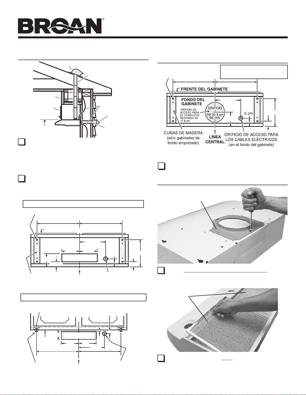
1 Determine si la descarga de la campana va a ser vertical [conducto
de 8.3 cm x 25.4 cm (3 ¼” x 10”) o conducto redondo de 17. 8 cm
(7”)], horizontal [sólo conducto de 8.3 cm x 25.4 cm (3 ¼” x 10”)] o
si es un sistema sin conductos. En el caso de descarga vertical u
horizontal, tienda los conductos entre el lugar donde va a instalar
la campana y la tapa de techo o la tapa de pared. Para obtener
los mejores resultados, utilice el número mínimo de transiciones
y codos.
2 Utilice los siguientes diagramas para colocar adecuadamente los
conductos y hacer el corte exacto para la conexión eléctrica en
el gabinete o en la pared. En el caso de aquellas instalaciones
en sistemas sin conductos, NO haga ningún orificio de acceso
para el conducto.
SISTEMA VERTICAL DE CONDUCTOS DE 8.3 cm x 25.4 cm (3 ¼” x 10”)
35,4 cm
43,0 cm
50,6 cm
(campana de 76,2 cm)
(campana de 91,4 cm)
(campana de 106,7 cm)
35,4 cm
43,0 cm
50,6 cm
(campana de 76,2 cm)
(campana de 91,4 cm)
(campana de 106,7 cm)
FRENTE DEL GABINETE
19,1 cm
,
,
12,7 cm
26,7 cm
3,8 cm
3 Haga las conexiones del cableado doméstico entre el panel de
servicio y el lugar donde va a instalar la campana.
PREPARACIÓN DE LA CAMPANA
PLACA DEL CONDUCTO
REDONDO DE 1 7. 8 CM (7”)
FONDO DEL GABINETE
19,1 cm
12,7 cm
13,3 cm
DEL CONDUCTO HORIZONTAL
13,3 cm
ORIFICIO DE ACCESO
3,2 cm
CUÑAS DE MADERA
(sólo gabinetes de
fondo empotrado)
LÍNEA
CENTRAL
ORIFICIO DE ACCESO PARA
LOS CABLES ELÉCTRICOS
(en el fondo del gabinete)
SISTEMA HORIZONTAL DE CONDUCTOS DE 8.3 cm x 25.4 cm (3 ¼” x 10”)
CUÑAS DE MADERA
(sólo gabinetes de fondo empotrado)
TORNILLOS PARA
EL MONTAJE DE
LA CAMPANA (4)
FRENTE DEL GABINETE
9,5 cm
FONDO DEL
GABINETE
35,4 cm (campana de 76,2 cm)
43,0 cm (campana de 91,4 cm)
50,6 cm (campana de 106,7 cm)
ORIFICIO DE ACCESO DEL
CONDUCTO HORIZONTAL
13,3cm13,3
CENTRAL
LÍNEA
0,32 cm
cm
19,1 cm
35,4 cm (campana de 76,2 cm)
43,0 cm (campana de 91,4 cm)
50,6 cm (campana de 106,7 cm)
ORIFICIO DE ACCESO
PARA LOS CABLES
ELÉCTRICOS (en la pared)
5 cm
1,9 cm
26,7 cm
3,8 cm
1 Quite la placa del conducto redondo de 17.8 cm (7”) de la parte
superior de la campana. Colóquela aparte, con los tornillos de
montaje.
FILTROS
2 Quite la cinta que sujeta los filtros en su lugar. Hale hacia abajo
sujetando las aletas del filtro o las cavidades para los dedos y
saque los filtros. Coloque los filtros a un lado.
Page 11
CAMPANA EXTRACTORA
ALLURE
SERIE QS2 ALLURE
®
QS2 SERIES
RANGE HOOD
Página 11
Page 11
®
PREPARACIÓN DE LA CAMPANA
3 Quite la Cubi-
erta inferior
recubierta de
®
Teflón
la campana.
Coloque a
un lado la
cubierta y los
tornillos de
montaje.
Teflon® es una marca
comercial registrada
de DuPont.
4 Quite el
conector del
regulador de
tiro/conector
del interior de
la campana.
Ponga aparte
el conector,
con los tornillos de montaje
y la bolsa de
piezas.
de
CUBIERTA INFERIOR RECUBIERTA DE
TEFLÓN
®
(Se encuentra fija con 2 tornillos)
PREPARACIÓN DE LA CAMPANA
CONDUCTO
7 Quite el con-
ducto para aire
- fijado con un
(1) tornillo.
NOTA: Tenga
cuidado de no
desconectar
ningún cable.
8 Quite el deflec-
tor del conducto
para aire.
PARA AIRE
CONECTOR DEL
REGULADOR DE
TIRO/CONDUCTO
5 Quite el
agujero ciego
para los
cables eléctricos, ya sea
el superior o
el posterior,
e instale una
grapa para
cable eléctrico aprobada.
GRAPA DEL CABLE ELÉCTRICO
Para instalaciones sin conducto, pase al Paso
15.
(3) #8 TORNILLOS
PANEL DE
ILUMINACIÓN
Los siguientes
pasos (del 6 al
14) son SÓLO
(2) #8 TORNILLOS
PARA INSTALACIONES
CON
CONDUCTO.
6 Quite el panel de iluminación - fijado con (3) #8 tornillos
y (2) #8 tornillos. Desconecte el juego del arnés del alambre (conectador blanco).
DEFLECTOR
DEFLECTOR
9 Gire el deflec-
tor. Vuelva
a insertar el
deflector en
el conducto
para aire de
manera (según lo demostrado) que las aletas
entren totalmente en las
ranuras del conducto
para aire. Un “tecleo”
audible será oído
cuando está instalado completamente.
Esto se cerrará del
aire atraviesa las
ranuras sin conductos encima de la
campana.
RANURAS
ALETAS
10
Reinstale el
conducto para
aire, vuelva al
conectar el arnés del alambre, y
substituya el panel de iluminación.
NOTA: Tenga cuidado de que ninguno
de los cables quede atrapado entre la aleta de apoyo y el
panel de iluminación.
ALETA DE APOYO
Page 12
®
ALLURE
CAMPANA EXTRACTORA
SERIE QS2 ALLURE
QS2 SERIES
RANGE HOOD
Página 12
Page 12
®
PREPARACIÓN DE LA CAMPANA
AGUJERO CIEGO
AGUJERO CIEGO SUPERIOR DEL
CONDUCTO RECTANGULAR
(Quite en el caso de descargas verticales de 8.3 cm x 25.4 cm
(3 ¼” x 10”) o de descargas
con conductos
redondos de
17.8 cm (7”)
AGUJERO CIEGO
POSTERIOR DEL
CONDUCTO RECTAN-
GULAR
(Quite en el caso de
descargas horizontales
de 8.3 cm x 25.4 cm
(3 ¼” x 10”)
11 Quite el agujero o agujeros ciegos para los conductos
apropiados de la parte superior o de la parte posterior de la
campana.
TORNILLO
SUJETADORES
PARA CONDUCTO SEMI-
CIRCULAR
(Quite en el caso de
descargas con conductos
redondos de 17.8 cm (7”)
PREPARACIÓN DE LA CAMPANA
AJUSTE
LATERAL
HASTA DE
2.5 CM (1”)
PIVOTE
13 Sólo para descargas con conductos de 8.3 cm x 25.4 cm (3
¼” x 10”): Quite la cinta de la aleta del regulador de tiro y
coloque el regulador de tiro/conector del conducto sobre
la abertura del agujero ciego, con los tornillos que quitó en el
paso 4 bajo “PREPARACIÓN DE LA CAMPANA”. Asegúrese
de que el pivote del regulador de tiro quede lo más cerca
posible del borde superior/posterior de la campana.
14 Sólo para descargas con conducto redondo de 17. 8 cm (7”):
Vuelva a instalar la placa del conducto redondo de 17.8
cm (7”) que quitó en el paso 1 bajo “PREPARACIÓN DE
LA CAMPANA”. Instale un regulador de tiro redondo de 7” (se
compra por separado). La aleta del regulador se debe abrir
libremente en dirección del flujo de aire (en sentido contrario
a la campana de la estufa).
N OTA
hasta de 2.5 cm (1”) desde el centro de la campana hacia cualquier lado o la
placa del conducto redondo de 1 7. 8 cm (7”) se pueden instalar a una distancia
hasta de 1. 3 cm (½”) desde el centro de la campana hacia cualquier lado. En
instalaciones excéntricas extremas, un extremo del conector de regulador de
conducto puede necesitar ser cortado al claro la grapa para cable eléctrico.
CINTA
Para acomodar los conductos descentrados, el conector del
regulador de tiro/conducto se pueden instalar a una distancia
BORDE SUPERIOR/
POSTERIOR
CONECTOR
DEL
REGULADOR DE
TIRO/CONDUCTO
(Se muestra la posición
de descarga vertical.)
CINTA DE METAL
12 Sólo para descarga horizontal: Quite la placa que se
encuentra enfrente del agujero ciego para la descarga
horizontal. Corte los sujetadores, levante la placa, sáquela
y deséchela. NO QUITE la cinta de metal que está sujeta
con dos tornillos.
PLACA
ALETA
RUEDA DEL
SOPALDOR
SECCIONES
ANILLO DE
RETENCIÓN
15 Las instalaciones don sistemas sin conductos solamente:
Requiren que se conecte un anillo de rendimiento en la
rueda del soplador.
Para instalar el anillo:
1. Saque la rueda del soplador moviéndola de lado a lado y
aplicnado una fuerza leve para separar la rueda del motor. Quite
el anillo de retención, en caso de necesidad.
2. Deslice el anillo dentro del extremo de diámetro pequeño de
la rueda y hacia abajo, hacia el borde de retención de la rueda.
3. Vuelva montar la rueda en el motor. Asegúrese de que la aleta
de la rueda quede dentro de una de las ranuras del motor.
4. Empuje la rueda hacia abajo hasta que quede fija en su lugar.
5. Verifique que la reda esté colocada adecuadamente, como se
mustra. Presione las secciones en su lagar, si es necesario.
Asugúrese de que la rueda gire libremente.
RANURAS
DEL MOTOR
EXTREMO DE DIAMETRO PEQUEÑO
ANILLO
BORDE DE
RETNECIÓN
Page 13
®
ALLURE
CAMPANA EXTRACTORA
SERIE QS2 ALLURE®
QS2 SERIES
RANGE HOOD
Page 13
Página 13
CONEXIÓN ELÉCTRICA
ADVERTENCIA: Para reducir el riesgo de descargas eléctricas, asegúrese de apagar el interruptor
de alimentación eléctrica en el panel de servicio.
Bloquee o rotule el panel de servicio para evitar
que alguien conecte accidentalmente la energía
eléctrica.
CABLEADO
DOMÉSTICO
(120 VCA)
CARTÓN
(Para proteger
la superficie de
la estufa.)
1 Haga la conexión eléctrica del suministro doméstico (120
VCA) en la campana. Si es necesario, use un pedazo de
cartón para proteger la superficie de la estufa.
INSTALACIÓN DE LA CAMPANA
ORIFICIO TIPO BACALLAVE (4)
1 Cuelgue la campana de los (4) tornillos de montaje (que se
encuentran en la bolsa de piezas). Deslice la campana hacia
la pared hasta que los tornillos de montaje queden conectados
en el extremo angosto de los (4) orificios tipo bocallave.
Apriete fijamente los tornillos de montaje. Un destornillador
largo funciona mejor.
2 Vuelva a colocar la cubierta inferior.
TORNILLO DE MONTAJE (4)
CINTA
PARA
CON-
DUCTOS
TORNILLO
VERDE DE
CO-
NEXIÓN
A TIERRA
2 Conecte el cable negro del suministro doméstico con el cable
negro de la campana, el cable blanco del suministro doméstico
con el cable blanco de la campana y la conexión a tierra del
suministro doméstico debajo del tornillo verde de conexión
a tierra. Apriete fijamente una grapa para cable eléctrico a
cableado doméstico.
3 Conecte el sistema de conductos en la campana. Use cinta
para conductos para fijar y sellar las uniones.
FOCO DE HALÓGE-
4 Instale (2) focos de halógeno PAR20, de 50 W máximo o (2)
R16 bulbos incandescentes del máximo de 40W. Compre
los bulbos por separado.
NO
PAR20,
50W MAX. (2)
- o -
R16, 40W MAX.
BULBOS
INCANDESCENTES
(2)
PRECAUCION: ¡Los bulbos pueden ser calientes!
!
Refiera a la empaqueta del bulbo para la información
adicional.
5 Vuelva a colocar los filtros, conecte la energía en el panel de
servicio, y revise el funcionamiento adecuado de la campana.
Page 14
®
ALLURE
CAMPANA EXTRACTORA
SERIE QS2 ALLURE®
QS2 SERIES
RANGE HOOD
Página 14
Page 14
FILTROS SIN CONDUCTOS
Si la campana se va a instalar en un sistema sin conductos:
Compre un juego de (2) filtros para sistemas sin conductos en la
tienda distribuidora o minorista de su localidad y sujete a los filtros
de malla de alumino.
NOTA: En el caso de los modelos que están instalados en la
modalidad sin conductos, la operación más eficiente
se logra a las velocidades 1 y 2. Estas velocidades
proporcionan la operación más eficiente y silenciosa
mientras se cocina, al mismo tiempo que maximizan las
ventajas del sistema de filtración recirculante.
OPERACIÓN
Ventilador y luces: 3 conmutadores de pulsadores para cada uno. Pre-
sione cualquier pulsador para seleccionar una de las tres velocidades
del ventilador o una de las tres intensidades de luz. Presione el mismo
pulsador para apagar el ventilador o la luz. Presione otro pulsador para
cambiar la velocidad del ventilador o la intensidad de la luz. Una luz verde
que se encuentra sobre cada pulsador indica la velocidad del ventilador.
Heat Sentry: La campana de su estufa está equipada con la característica Heat Sentry que supervisa y controla la temperatura. Cuando
la temperatura sea mayor que la normal, la característica Heat Sentry
encenderá automáticamente el ventilador a la velocidad más alta.
1. Si hay un ajuste seleccionado del ventilador cuando Heat Sentry está
funcionando, la luz indicadora que se encuentra sobre el pulsador
del ventilador destellará.
2. Si el ajuste del ventilador está apagado cuando Heat Sentry está
funcionando, la luz que se encuentra sobre el pulsador 3 del ventilador
destellará rápidamente.
Cuando la temperatura disminuye hasta el valor normal, el ventilador
regresará al ajuste que tenía antes de que la característica Heat Sentry
se encendiera.
Fusible: El control para campana tiene un fusible protector contra sobrevoltaje. Si el fusible está abierto (se fundió), los indicadores
de nivel del ventilador funcionarán adecuadamente cuando se presionen
los botones o los conmutadores del ventilador, pero ni el ventilador ni
las luces se encenderán.
El fusible es de acción rápida, 5 x 20 mm, 10 amperios y 125 V (como
mínimo). Los fabricantes comunes y números de piezas correspondientes son: Littlefuse, 217010; Bussmann, GMA10A; Wickmann, 1942100.
Radio Shack, Digikey (1-800-344-4539), y la mayoría de las tiendas de
accesorios eléctricos los tienen a la venta.
Para reemplazar el fusible:
1. Desconecte la energía en la entrada de servicio.
2. Quite los filtros, el panel inferior, el grupo de conductores de la luz y
el conducto de aire.
3. Quite y revise el fusible. Si no está abierto (fundido), necesitará
realizar pruebas diagnósticas adicionales.
4. Instale un fusible nuevo.
5. Vuelva a montar el conducto de aire, el grupo de conductores de la
luz, el panel inferior y los filtros.
6. Restablezca la energía y revise la operación del control y de la campana.
erdes
v
LIMPIEZA
ADVERTENCIA: Para reducir el riesgo de una descarga
eléctrica, desconecte el suministro eléctrico antes de
limpiar la unidad.
Filtros de malla de aluminio: Limpie frecuentemente los filtros con agua
caliente y un detergente suave. Los filtros se pueden lavar en lavaplatos.
Filtros de carbón: NO sumerja los filtros en agua ni los coloque en el
lavaplatos. Reemplace los filtros aproximadamente cada 6 meses. La característica especial “Clean Sense” (Detección de limpieza) indica cuando
se debe reemplazar el filtro. Las líneas azules y amarillas se combinarán
produciendo un color verde cuando sea el momento de cambiar el filtro. La
característica “Clean Sense” funciona mejor cuando se coloca orientada
hacia la superficie para cocinar.
Para limpiar la campana: Quite los filtros. Use un paño húmedo y un
detergente suave para limpiar las superficies con grasa. No use paños
abrasivos, almohadillas de lana de acero, ni polvo desengrasador en la
cubierta inferior recubierta de Teflón
Tenga cuidado cuando limpie la hoja del ventilador. No se debe doblar ni
desalinear. NO PERMITA LA ENTRADA DE AGUA EN EL MOTOR. Asegúrese de que todas las superficies estén completamente secas antes de
volver a colocar los filtros y conectar la energía eléctrica.
El motor está permanentemente lubricado. No lubrique ni desmonte el motor.
®
es una marca comercial registrada de DuPont.
Teflon
®
ni en ninguna superficie pintada.
Page 15
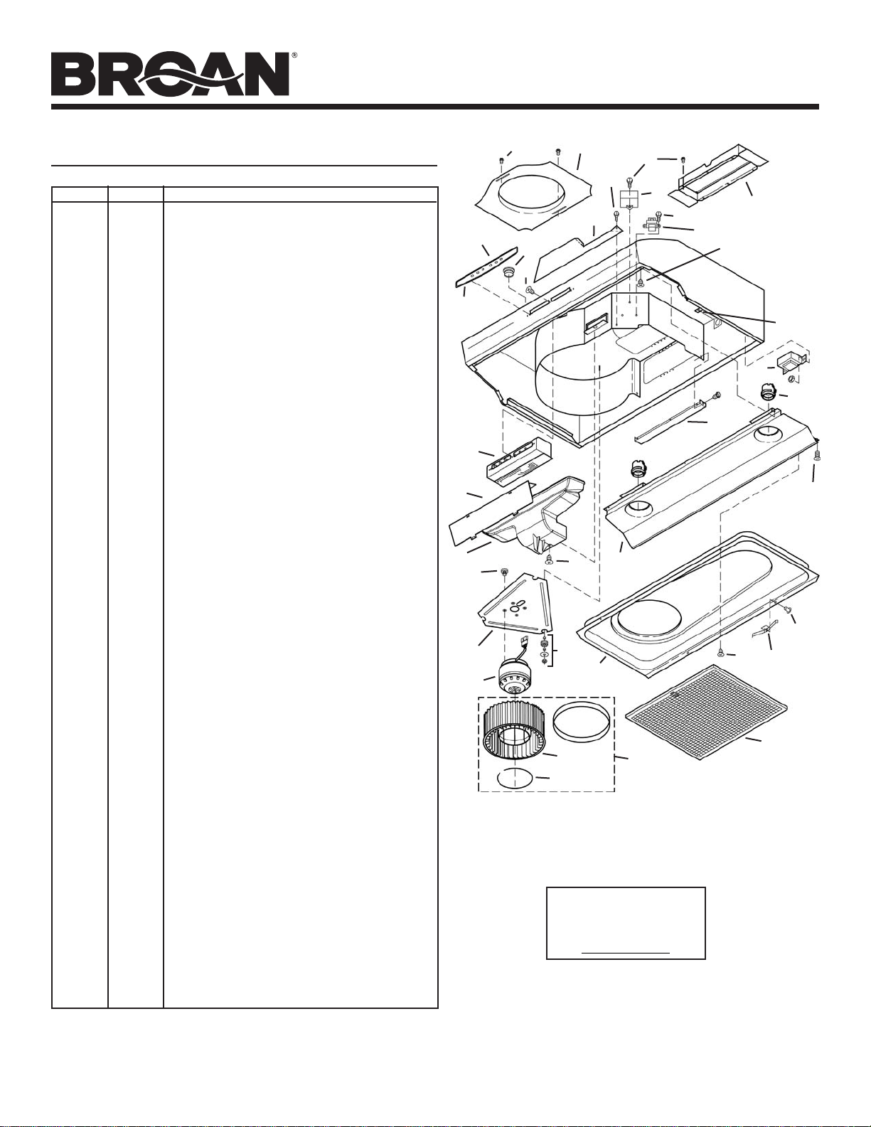
PIEZAS DE SERVICIO
CLAVE N.º PIEZA N.º DESCRIPCIÓN
1 R680508 Placa de conducto redondo de 7” (17.7 cm) (incluye herraje)
2 R740013 Regulador de tiro/conectador de conducto(incluye herraje)
3 R602017 Tornillo hexagonal, #8-18 x ¼ Hex* (2 en el paquete)
4 R334755 Capacitor del motor (incluye tuercas para alambre y herraje)
5 R501031 Transformador de aislamiento
6 R627501 Placa de datos, blanca
R627502 Placa de datos, almendra
R627503 Placa de datos, negra
R627528 Placa de datos, café pálido
7 R169005 Panel de control, blanco (incluye clave N.º 6 y herraje)
R169006 Panel de control, almendra(incluye clave N.º 6 y herraje)
R169007 Panel de control, negro (incluye clave N.º 6 y herraje)
R169008 Panel de control, café pálido (incluye clave N.º 6 y herraje)
8 R601535 Tornillo para plástico, #6 x 1/2, de cabeza plana
(3 en el paquete)
9 R602534 Tornillo, #8-18 x 3/8 (2 en el paquete)
10 R602533 Tornillo de conexión a tierra
11 R680505 Cubierta deslizante, tomacorriente (incluye herraje)
12 R680507 Cubierta deslizante, frente (incluye herraje)
13 R111663 Conjunto del control (incluye claves N.º 6, 7 y herraje)
14 R401647 Juego de conducto para aire (incluye clave no. 15 y herraje)
15 R401646 Deflector
16 R601536 Tornillos métricos M4 x 6 mm (4 en el paquete)
17 R651973 Placa del motor (incluye clave N.º 18)
18 R169009 Juego de montaje de la placa del motor (3 de cada parte)
19 R520132 Motor (incluye clave N.º 17)
20 R531068 Rueda del ventilador (incluye clave N.º 21)
21 R607215 Anillo de retención
22 R111630 Conjunto del receptáculo de la lámpara
23 R7201731 Panel de luces, 30” (75 cm), blanco
R7201751 Panel de
R7201771 Panel de luces, 42” (105 cm), blanco
R7201732 Panel de luces, 30” (75 cm), almendra
R7201752 Panel de luces, 36” (90 cm), almendra
R7201772 Panel de luces, 42” (105 cm), almendra
R7201734 Panel de luces, 30” (75 cm), negro
R7201754 Panel de luces, 36” (90 cm), negro
R7201774 Panel de luces, 42” (105 cm), negro
R7201735 Panel de luces, 30” (75 cm), café pálido
R7201755 Panel de luces, 36” (90 cm), café pálido
R7201775 Panel de luces, 42” (105 cm), café pálido
R720174 Panel de luces, 30” (75 cm), de acero inoxidable
R720176 Panel de luces, 36” (90 cm), de acero inoxidable
R720178 Panel de luces, 42” (105 cm), de acero inoxidable
24 R607660 Tapón (1 req.)
25 * Remache tubular .1250 (3 req.)
26 R169016 Juego del resorte del filtro
27 R680511 Cubierta inferior, 30” (75 cm) (incluye claves N.º 9, 25 y 26)
R680520 Cubierta inferior, 36” (90 cm) (incluye claves N.º 9, 25 y 26)
R680527 Cubierta inferior, 42” (105 cm) (incluye claves N.º 9, 25 y 26)
28 R501034 Autotransformador (incluye herraje)
29 99010302 Filtro de malla de aluminio, 30” (75 cm)(2 en el paquete)
99010303 Filtro de malla de aluminio, 36” (90 cm)(2 en el paquete)
99010304 Filtro de malla de aluminio, 42” (105 cm)(2 en el paquete)
30 R730111 Conjunto de rueda del ventilador, sin conductos
(incluye claves N.º 20 y 21)
** 99010308 Juego de filtros para sistemas sin conductos, 30” (75
** 99010309 Juego de filtros para sistemas sin conductos, 36” (90 cm)
** 99010310 Juego de filtros para sistemas sin conductos, 42” (105 cm)
** R111627 Harness de alambres
** R564074 Fusible de control, 10-Amp
Pida piezas de repuesto indicando el N.º de la PIEZA, no el N.º de la CLAVE
*Herraje estándar, se puede comprar en la localidad.
** No se ilustra, se compra por separado
luces, 36”
(90 cm), blanco
cm)
15
14
®
ALLURE
CAMPANA EXTRACTORA
SERIE QS2 ALLURE
QS2 SERIES
RANGE HOOD
®
Page 15
3
6
24
8
7
13
16
17
19
1
12
9
18
27
20
21
Las piezas de recambio
se pueden ahora pedir en
nuestro Web site.
Visítenos por favor en
www.Broan.com
3
3
23
4
3
30
2
5
9
10
28
22
11
9
9
9
26
29
Page 16
®
ALLURE
CAMPANA EXTRACTORA
SERIE QS2 ALLURE
QS2 SERIES
RANGE HOOD
Página 16
Page 16
GARANTIA
GARANTIA BROAN-NUTONE LIMITADA POR UN AÑO
Broan-NuTone garantiza al consumidor comprador original de sus productos que dichos productos carecerán de defectos en materiales
o en mano de obra por un período de un año a partir de la fecha original de compra. NO EXISTEN OTRAS GARANTIAS, EXPLICITAS
O IMPLICITAS, INCLUYENDO, PERO NO LIMITADAS A, GARANTIAS IMPLICITAS DE COMERCIALIZACION O APTITUD PARA UN
PROPOSITO PARTICULAR.
Durante el período de un año, y a su propio criterio, Broan-NuTone reparará o reemplazará, sin costo alguno cualquier producto o pieza
que se encuentre defectuosa bajo condiciones normales de servicio y uso.
ESTA GARANTIA NO SE APLICA A TUBOS Y ARRANCADORES DE LAMPARAS FLUORESCENTES. Esta garantía no cubre (a)
mantenimiento y servicio normales o (b) cualquier producto o piezas que hayan sido utilizadas de forma errónea, negligente, que hayan
causado un accidente, o que hayan sido reparadas o mantenidas inapropiadamente (por otras compañías que no sean Broan-NuTone),
instalación defectuosa, o instalación contraria a las instrucciones de instalación recomendadas.
La duración de cualquier garantía implícita se limita a un período de un año como se especifica en la garantía expresa. Algunos estados
no permiten limitaciones en cuanto al tiempo de expiración de una garantía implícita, por lo que
no aplicarse a usted.
LA OBLIGACION DE BROAN-NUTONE DE REPARAR O REEMPLAZAR, SIGUIENDO EL CRITERIO DE BROAN-NUTONE, DEBERA
SER EL UNICO Y EXCLUSIVO RECURSO LEGAL DEL COMPRADOR BAJO ESTA GARANTIA. BROAN-NUTONE NO SERA RESPONSABLE POR DAÑOS INCIDENTALES, CONSIGUIENTES, O POR DAÑOS ESPECIALES QUE SURJAN A RAIZ DEL USO O
DESEMPEÑO DEL PRODUCTO. Algunos estados no permiten la exclusión o limitación de daños incidentales o consiguientes, por lo
que la limitación antes mencionada puede no aplicarse a usted.
Esta garantía le proporciona derechos legales específicos, y usted puede también tener otros derechos, los cuales varían de estado a
estado. Esta garantía reemplaza todas las garantías anteriores.
Para calificar en la garantía de servicio, usted debe (a) notificar a Broan-NuTone al domicilio o al número de teléfono abajo, (b) dar el
número del modelo y la identificación de la pieza, y (c) describir la naturaleza de cualquier defecto en el producto o pieza. En el momento
de solicitar servicio cubierto por la garantía, usted debe de presentar evidencia de la fecha original de compra.
Broan-NuTone LLC Hartford, Wisconsin www.broan.com 800-558-1711
la limit
ación antes mencionada puede
®
626978D
 Loading...