

Page 1
INSTALLATION INSTRUCTIONS
HB0073
E60000LC SERIES
! !
INTENDED FOR DOMESTIC COOKING ONLY
READ AND SAVE THESE INSTRUCTIONS
INSTALLER: LEAVE THIS MANUAL WITH HOMEOWNER.
HOMEOWNER: USE AND CARE INFORMATION ON PAGES 13 & 14.
Venmar Ventilation ULC; Drummondville, Québec www.broan.ca 877-896-1119
REGISTER YOUR PRODUCT ONLINE AT: www.broan.ca
21241 rev. 02
Page 2

!
WARNING
!
WARNING
TO REDUCE THE RISK OF FIRE, ELECTRIC SHOCK OR
INJURY TO PERSONS, OBSERVE THE FOLLOWING:
1. Use this unit only in the manner intended by the manufacturer.
If you have questions, contact the manufacturer at the address
or telephone number listed in the warranty.
2. Before servicing or cleaning unit, switch power off at service
panel and lock service disconnecting means to prevent
power from being switched on accidentally. When the service
disconnecting means cannot be locked, securely fasten a
prominent warning device, such as a tag, to the service panel.
3. Installation work and electrical wiring must be done by
qualified personnel in accordance with all applicable codes
and standards, including fire-rated construction codes and
standards.
4. Sufficient air is needed for proper combustion and exhausting
of gases through the flue (chimney) of fuel burning equipment
to prevent backdrafting. Follow the heating equipment
manufacturer’s guidelines and safety standards such as
those published by the National Fire Protection Association
(NFPA) and the American Society for Heating, Refrigeration
and Air Conditioning Engineers (ASHRAE) and the local code
authorities.
5. When cutting or drilling into wall or ceiling, do not damage
electrical wiring and other hidden utilities.
6. Ducted fans must always be vented outdoors.
7. Do not use this unit with any additional solid-state speed
control device.
8. To reduce the risk of fire, use only metal ductwork.
9. This unit must be grounded.
10. When applicable local regulations comprise more
restrictive installation and/or certification requirements,
the aforementioned requirements prevail on those of this
document and the installer agrees to conform to these at his
own expenses.
TO REDUCE THE RISK OF A RANGE TOP GREASE FIRE:
a) Never leave surface units unattended at high settings. Boilovers
cause smoking and greasy spillovers that may ignite. Heat oils
slowly on low or medium settings.
b) Always turn hood ON when cooking at high heat or when
flambeing food (i.e.: Crêpes Suzette, Cherries Jubilee,
Peppercorn Beef Flambé).
c) Clean ventilating fans frequently. Grease should not be allowed
to accumulate on fan, filters or in exhaust ducts.
d) Use proper pan size. Always use cookware appropriate for the
size of the surface element.
TO REDUCE THE RISK OF INJURY TO PERSONS IN THE
EVENT OF A RANGE TOP GREASE FIRE, OBSERVE
THE FOLLOWING*:
1. SMOTHER FLAMES with a close-fitting lid, cookie sheet or
metal tray, then turn off the burner. BE CAREFUL TO PREVENT
BURNS. IF THE FLAMES DO NOT GO OUT IMMEDIATELY,
EVACUATE AND CALL THE FIRE DEPARTMENT.
2. NEVER PICK UP A FLAMING PAN — You may be burned.
3. DO NOT USE WATER, including wet dishcloths or towels —
This could cause a violent steam explosion.
4. Use an extinguisher ONLY if:
A. You own a Class ABC extinguisher and you know how to
operate it.
B. The fire is small and contained in the area where it started.
C. The fire department has been called.
D. You can fight the fire with your back to an exit.
* Based on “Kitchen Fire Safety Tips” published by NFPA.
CAUTION
1. For indoor use only.
2. For general ventilating use only. Do not use to exhaust
hazardous or explosive materials and vapors.
3. To avoid motor bearing damage and noisy and/or unbalanced
impellers, keep drywall spray, construction dust, etc. off power
unit.
4. Your hood motor has a thermal overload which will automatically
shut off the motor if it overheats. The motor will restart when it
cools down. If the motor continues to shut off and restart, have
the hood serviced.
5. For best capture of cooking impurities, the bottom of the hood
should be at a minimum of 24" and at a maximum of 30" above
the cooking surface. For a gas range, the bottom of the hood
MUST NOT BE LESS than 30” above cooktop.
6. Two installers are recommended because of the large size and
weight of this hood.
7. To reduce the risk of fire and to properly exhaust air, be sure to
duct air outside — Do not exhaust air into spaces within walls
or ceiling or into attics, crawl space or garage.
8. This product is equipped with a thermostat which may start
blower automatically. To reduce the risk of injury and to prevent
power from being switched on accidentally, switch power off at
service panel and lock or tag service panel.
9. Because of the high exhausting capacity of this hood, you
should make sure enough air is entering the house to replace
exhausted air. Use an appropriate make-up air device or open
a window close to or in the kitchen.
10. To reduce the risk of fire and electric shock, the Broan Elite
E60E Series hood must be installed with one Broan exterior
blower model 331H, 332H, 335 or 336; or one Broan in-line
blower model HLB3, HLB6, HLB9 ou HLB11. Other blowers
cannot be substituted. (Exterior or in-line blowers sold
separately.)
11. Please read specification label on product for further
information and requirements.
2
Page 3
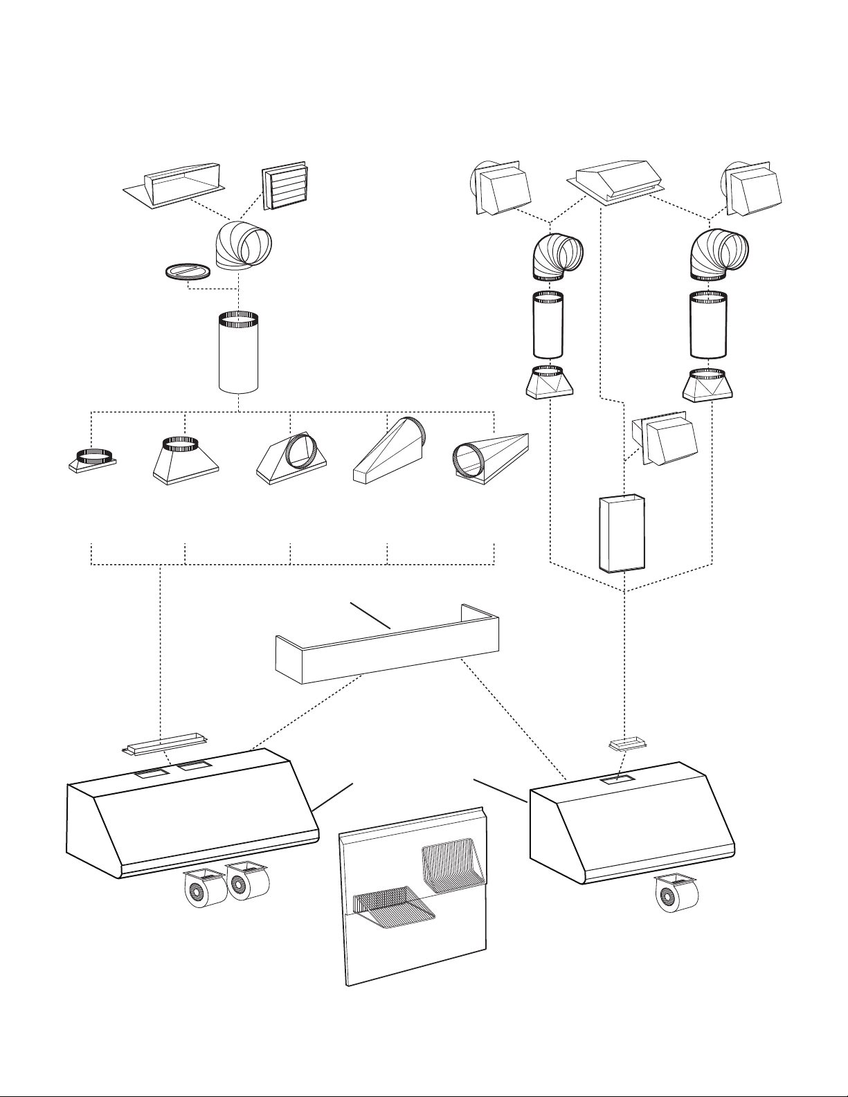
- E60000LC SERIES RANGE HOOD SYSTEM -
INTERNAL BLOWERS
MODEL 437
(HIGH CAPACITY ROOF CAP)
MODEL 421
(10" ROUND VERTICAL
IN-LINE DAMPER)
MODEL 427
(4½" X 18½"
TO 10" ROUND,
(4½" X 18½"
TO 10" ROUND -
6" HIGH - LATERAL)
MODEL 423
VERTICAL)
M
ODEL 441
(10" ROUND WALL CAP)
MODEL 418
(10" ROUND
ADJUSTABLE ELBOW)
MODEL 410
(10" ROUND DUCT
— 2 FT. SECTIONS)
MODEL 424
(4½" X 18½"
TO 10" ROUND -
HORIZ. FRONT/REAR)
MODEL 454
(4½" X 18½"
TO 10" ROUND -
HORIZ. /RIGHT)
M
ODEL 647
(7" ROUND WALL CAP )
MODEL 415
(7" ROUND
ADJUSTABLE ELBOW)
MODEL 407
(7" ROUND
— 2 FT. SECTIONS)
ODEL 412
M
TRANSITION
(3¼" X 10" TO 7")
MODEL 453
(4½" X 18½"
TO 10" ROUND -
HORIZ. /LEFT)
MODEL 634 OR 644
(ROOF CAP)
(3¼" X 10" TO 8")
M
ODEL 639
(3¼" X 10"
WALL CAP)
8" ROUND
ADJUSTABLE
ELBOW
M
ODEL 413
TRANSITION
TANDARD
S
DUCT
(3¼" X 10")
MODEL 643
(8" ROUND WALL CAP )
8" R
OUND
STANDARD
DUCT
ADAPTER 4½" X 18½"
(SUPPLIED WITH
DOUBLE BLOWER HOOD)
HL0173
D
UAL BLOWER (1200 CFM)
36", 42" AND 48" ONLY
OPTIONAL DECORATIVE
FLUE AEE SERIES
E60000LC SERIES HOOD
RMP SERIES
BACKSPLASH
(STAINLESS STEEL WALL
COVERING
WITH WARMING
SHELVES. OPTIONAL)
DAPTER/DAMPER 3¼" X 10"
A
(SUPPLIED WITH
BLOWER HOOD)
SINGLE
INGLE BLOWER (600 CFM)
S
3
Page 4
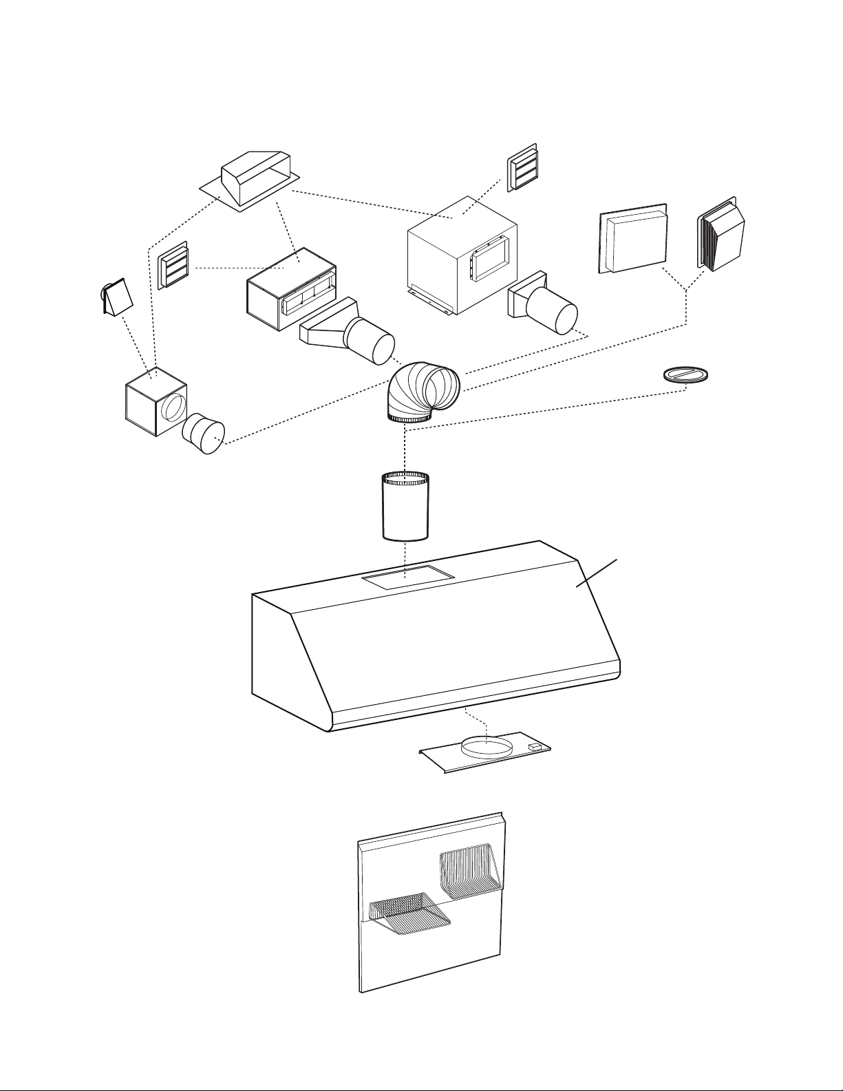
MODEL 643
(8" ROUND
WALL CAP)
- E60000LC SERIES RANGE HOOD SYSTEM -
IN-LINE AND EXTERIOR BLOWERS
ODEL 441
M
ODEL 437
IGH CAPACITY ROOF CAP)
(H
ODEL 441
M
(10" ROUND
WALL CAP)
ODEL HLB6 (660 CFM)
M
N-LINE BLOWER
I
(INCLUDES TWO 4½" X 18½" TO
10" ROUND TRANSITIONS)
MODEL HLB9 (800 CFM)
OR HLB11 (1100 CFM)
IN-LINE BLOWER
(INCLUDES TWO 8" X 12" TO
10" ROUND TRANSITIONS)
M
(10" ROUND WALL CAP)
ODEL 331H (600 CFM)
M
OR 332H (900 CFM)
EXTERIOR BLOWER
MODEL 335 (1200 CFM)
OR 336 (1500 CFM)
EXTERIOR BLOWER
M
ODEL HLB3 (280 CFM)
IN-LINE BLOWER
(INCLUDES ONE 8" TO 10"
ROUND TRANSITION)
ODEL 418
M
(10" ROUND
ADJUSTABLE ELBOW)
M
ODEL 410
(10" ROUND DUCT
- 2FT. SECTIONS)
E60000LC SERIES HOOD
332KR IN-LINE AND
EXTERIOR BLOWER ROUGH-IN KIT
(SUPPLIED WITH HOOD)
MODEL 421
(10" ROUND VERT.
IN-LINE DAMPER)
RECOMMENDED FOR
USE
WITH EXTERIOR
BLOWERS
HL0100
RMP SERIES BACKSPLASH
TAINLESS STEEL WALL COVERING
(S
WITH WARMING SHELVES.
OPTIONAL)
4
Page 5
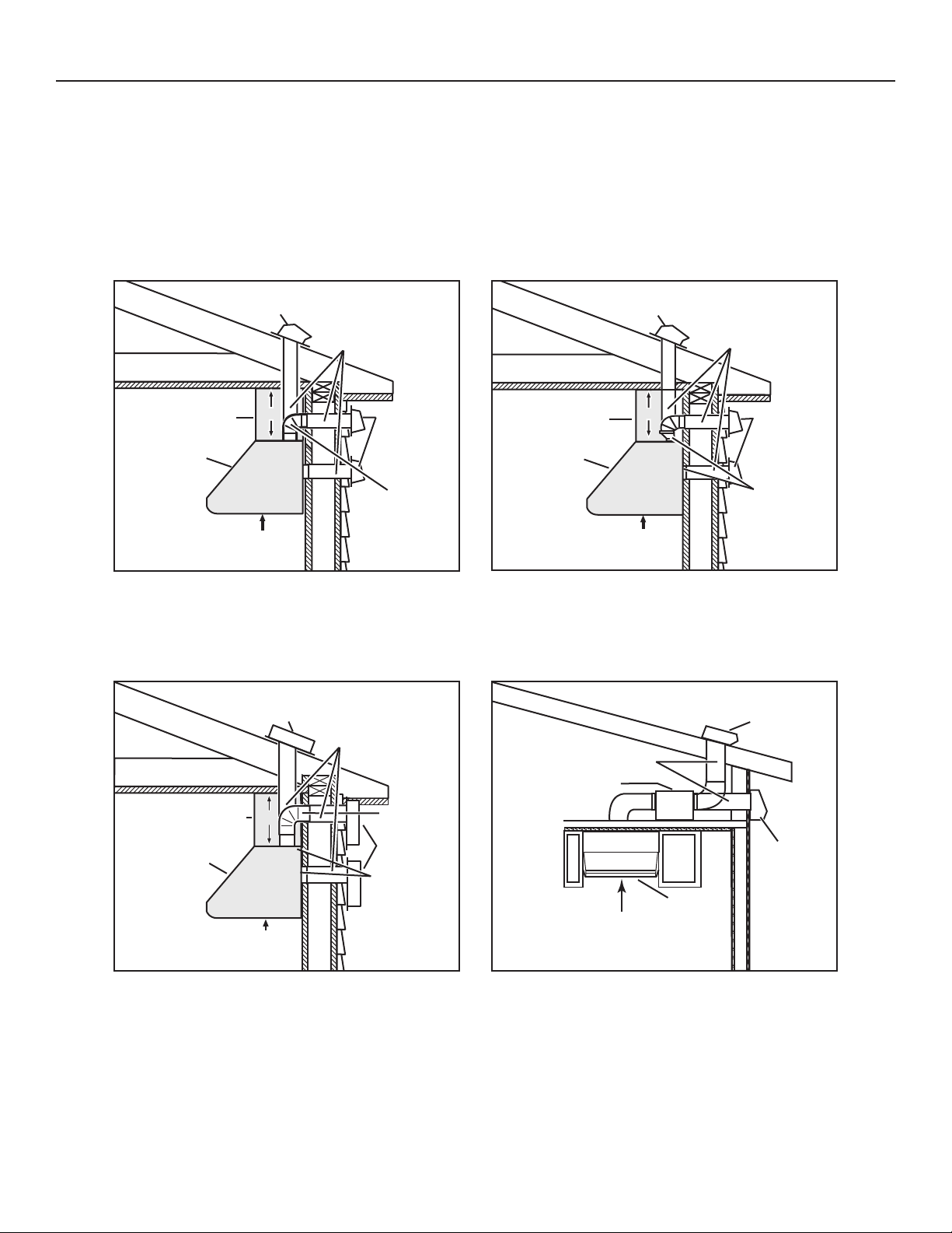
1. SELECT BLOWER OPTION
The Broan Elite E60000LC Series range hood includes many configurations: hoods with single or double internal blowers (included with
the hood), or hoods using external blowers. For this last category, the Broan Elite E60000LC Series must be installed with in-line blower
models HLB3, HLB6, HLB9 or HLB11, or exterior blower models 331H, 332H, 335 or 336 only. Other blowers cannot be substituted
(blowers sold separately).
Plan where and how the ductwork will be installed.
If installing an in-line blower, refer to instructions packed with in-line blower and follow steps 1, 2, 3, 4, 6, 10 and up of this manual.
Install proper-sized ductwork, elbows and roof or wall cap for the type of blower you are installing. If using 7”, 8” or 10” round ducts, use a
transition (internal blowers only). Use 2” metal foil duct tape to seal duct joints.
ROOF CAP
DECORATIVE FLUE
or SOFFIT
HOOD
24” MINIMUM ABOVE
COOKING SURFACE
(30” FOR GAS RANGE)
HH0088A
12”
ONE INTERNAL BLOWER
TYPICAL DUCTWORK
EXTERIOR BLOWER
DECORATIVE FLUE
OR SOFFIT
HOOD
24” MINIMUM ABOVE
COOKING SURFACE
HH0090A
(30” FOR GAS RANGE)
12 ”
7” or 8” ROUND
OR 3¼” x 10” DUCT
WALL CAP
7” or 8” ROUND
OR 3¼” x 10”
RECTANGULAR
ELBOW
10” ROUND
DUCT
10” ROUND
ELBOW
EXTERIOR
BLOWER
332KR
ROUGH-IN KIT
(see page 4)
DECORATIVE FLUE
or SOFFIT
HOOD
24” MINIMUM ABOVE
COOKING SURFACE
(30” FOR GAS RANGE)
HH0089A
TWO INTERNAL BLOWERS
TYPICAL DUCTWORK
(except HLB3, 8’’ ROUND DUCT)
HH0091A
10” ROUND DUCT
IN-LINE BLOWER
24” MINIMUM ABOVE
COOKING SURFACE
(30” FOR GAS RANGE)
ROOF CAP
12”
HOOD
10” ROUND DUCT
WALL CAP
4½” x 18½”
TO 10”
ROUND
TRANSITION
(see page 3)
ROOF CAP
WALL
CAP
MODEL 331H, 332H, 335 OR 336
EXTERIOR BLOWER TYPICAL DUCTWORK
MODEL HLB3, HLB6, HLB9 OR HLB11
IN-LINE BLOWER TYPICAL DUCTWORK
5
Page 6
2. MEASURE INSTALLATION
!
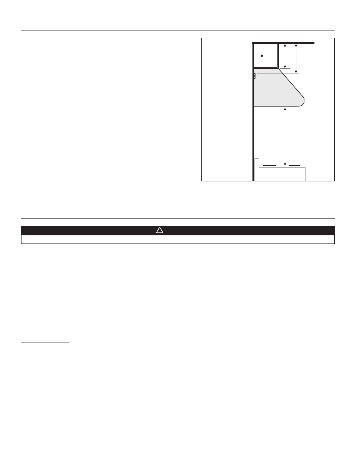
Dimensions for the most common installation are illustrated at right.
The minimum hood distance above cooktop is 24" for electric ranges,
and 30" for gas ranges.
A maximum of 30" above cooktop is highly recommended for best capture
of cooking impurities.
Distances over 30" are at the installer and users discretion.
Cabinet, soffit,
or decorative flue
HH0236A
A
Hood
24” minimum above
cooking surface
(30” for gas range)
Standard 36”
high cooktop
MINIMUM DISTANCE
ABOVE COOKTOP
Ceiling
Top of wood
mounting strip
A + 2’’
3. PREPARE THE INSTALLATION
WARNING
When performing installation, servicing or cleaning the unit, it is recommended to wear safety glasses and gloves.
NOTE: Before proceeding to the installation, check the contents of the box. If items are missing or damaged, contact the manufacturer.
Remove the installation kit from inside the hood.
Make sure that the following items are included:
- Wood strip (attached to back of hood)
- Accessories including:
• Baffle filters with handles: 30" and 36" hoods come with 3 baffle filters; 42" and 48" hoods come with 4 baffle filters
• 3¼" x 10" adapter/damper (included with internal single blower hood, see page 8 to locate the adapter)
• 4½" x 18½" adapter (included with internal double blower hood, see page 8 to locate the adapter)
• In-line and exterior blower rough-in plate model 332KR (mounted inside all external blower hoods)
• Bag of parts including:
4 flat head screws no. 10-2", 8 screws no. 8 x 3/4", 2 wire connectors, 3 wall anchors,
3 washers 13/64" ID x 3/4" OD, 1 wire clamp, 8 mechanical screws no. 8-32 x 1/4", 4 no. 8 x 3/8" screws
Parts sold separately:
- In-line blower assembly HLB3, HLB6, HLB9 or HLB11 (all include transition)
- Exterior blower assembly 331H, 332H, 335 or 336
- RMP Series Backsplash (optional)
- AEE Series Decorative flue, to be installed over the hood (optional)
- Transitions, duct, elbows, dampers, wall and roof caps.
Refer to pages 3 and 4 for a complete list of venting options and model numbers.
6
Page 7
3. PREPARE THE INSTALLATION (CONT’D)
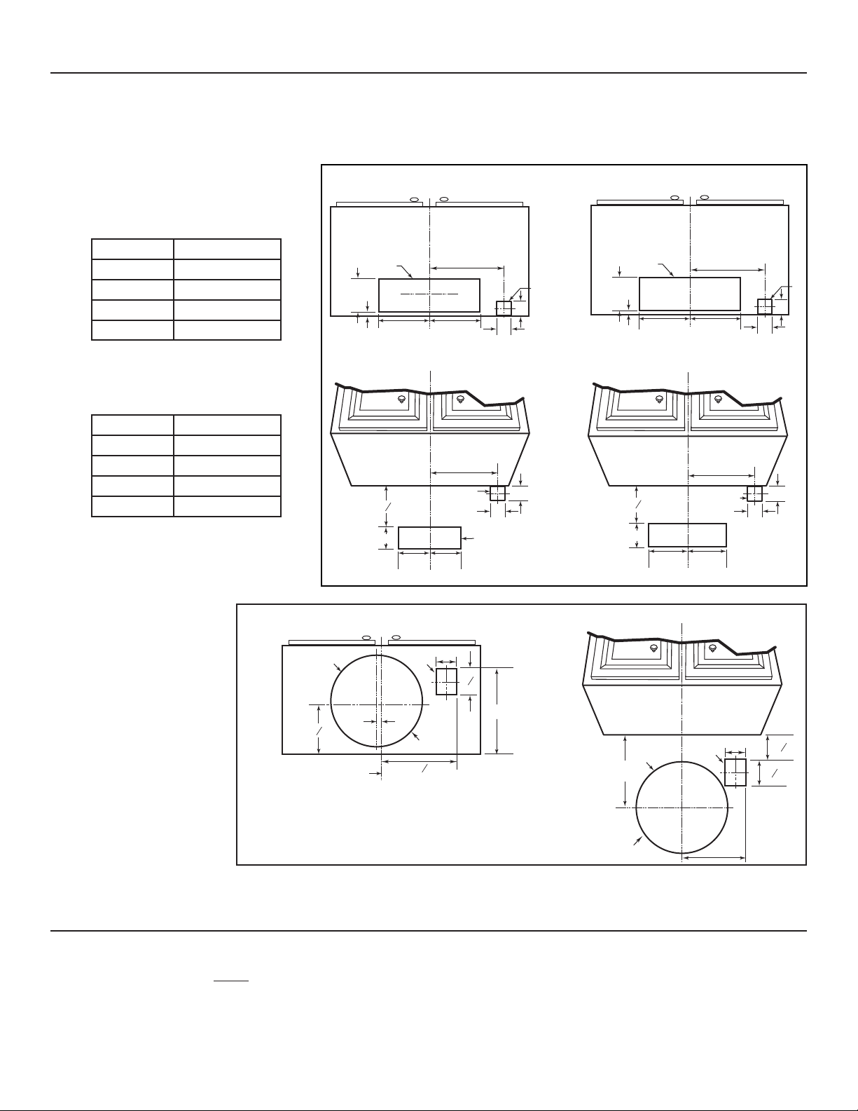
Cut-out the openings for duct (A) and power cable (B), in cabinet or wall, according to the direction of discharge chosen.
See figures below.
NOTE: For all internal blower hoods, the cut-out opening for house wiring can be made in cabinet bottom OR wall, no matter the
discharge chosen (vertical or horizontal).
VERTICAL DISCHARGE
HOOD WIDTHS DIMENSION C
30" 13"
36" 16"
42" 19"
48" 22"
HORIZONTAL DISCHARGE
HOOD WIDTHS DIMENSION C
30" 13"
36" 16"
42" 19"
48" 22"
INTERNAL SINGLE BLOWER HOOD
CABINET BOTTOM VIEW
C
L
A
C
3¾”
7/8”
5¼”5¼”
INTERNAL SINGLE BLOWER HOOD
C
L
C
B
1
9
8”
3¾”
2”
A
5¼” 5¼”
HD0266A
INTERNAL DOUBLE BLOWER HOOD
CABINET BOTTOM VIEW
C
L
A
B
5½”
2”
2”
1/2”
22”
B
2”
10”10”
2”
INTERNAL DOUBLE BLOWER HOOD
C
L
22”
2”
3
8
8”
2”
B
2”
5½”
10” 10”
HOOD WITH IN-LINE OR EXTERIOR BLOWER
HOOD WITH IN-LINE OR EXTERIOR BLOWER
CABINET BOTTOM VIEW
A
3/8”
7
5
8”
CABINET CENTER LINE
HD0286A
C
L
B
Ø 10½”
9³
8”
3½”
7
4
8”
C
L
10¼”
9¾”
Ø 10½”
3½”
A
B
9¾”
³
5
8”
7
4
8”
4. INSTALL BACKSPLASH (OPTIONAL)
(Optional) RMP Series
Backsplash must be installed before the hood shell because the hood shell covers the backsplash top mounting screws. In order to be able
to install the backsplash, make sure you have at least 18’’ clearance between bottom of hood and range control panel or cooktop. (See
instructions packed with backsplash.)
7
Page 8
5. CHOOSE THE OPENING(S) (INTERNAL BLOWER(S) HOOD ONLY)
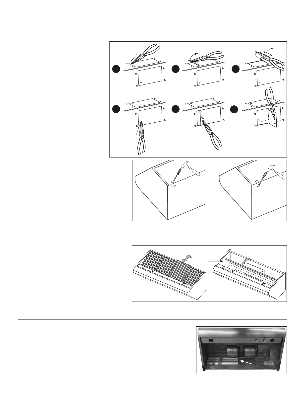
Remove the knockout(s) for the chosen opening(s) (horizontal at the back of the hood or vertical on top). See illustrations below.
1
VERTICAL DISCHARGE
1
HORIZONTAL DISCHARGE
HR0021
Punch out the appropriate electrical knockout hole on
top (A) or back (B) of the hood. Install the wire clamp
(included in parts bag).
2 3
2
AB
3
HD0250
6. REMOVE THE FILTERS AND THE GREASE DRIP RAIL
NOTE: For 36” wide double blower hood, the adapter is
taped on top of the filters. Remove adapter and
set aside before removing filters.
A. Remove tape on filters.
Remove filters from hood and set aside.
NOTE: It is recommended to start with the
middle one(s).
B. Lift out grease drip rail (1) and set aside.
HD0578
AB
7. REMOVE THE ADAPTER (INTERNAL BLOWER HOOD ONLY)
For all hoods, except the 36” wide double blower hood, remove the adapter (1), or
adapter/damper, taped inside the hood.
1
1
HD0581
8
Page 9
8. HORIZONTAL DISCHARGE INSTALLATION (INTERNAL BLOWER(S) HOOD ONLY)
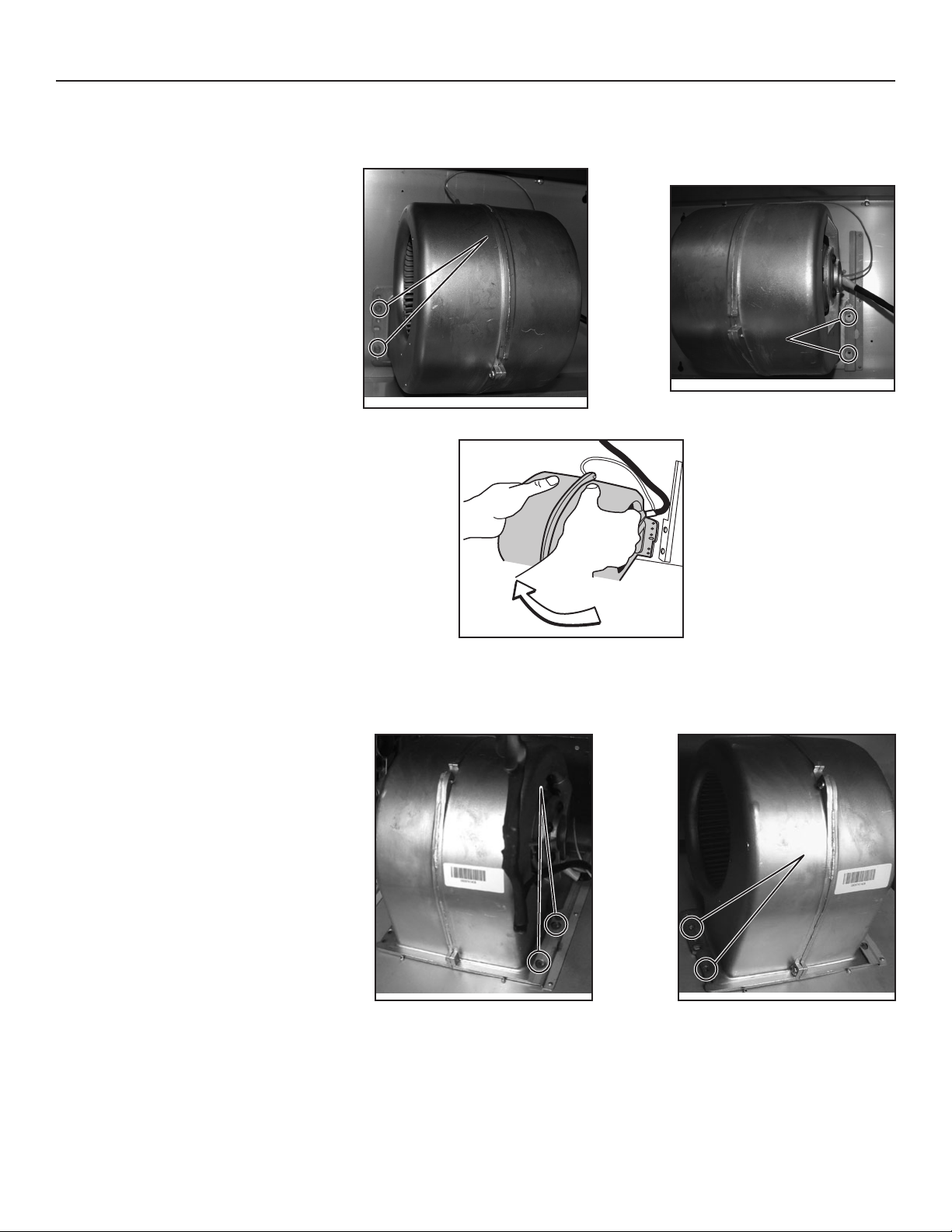
All internal blower hoods are factory shipped with the blower(s) mounted for a vertical discharge configuration. For a horizontal discharge
configuration, disassemble the blower(s) from the inner top of the hood and mount it (them) to the inner back panel of the hood. The
procedure below applies for one or two blowers.
LEFT SIDE MOUNTING
SCREWS LOCATION
Using a 5/16" socket, remove all blower mounting
screws from the inner top of the hood. Keep the
screws for further use.
RIGHT SIDE
MOUNTING SCREWS
LOCATION
HD0282
HD0269
Slide the blower to disengage its flange from the retaining bracket.
Rotate the blower and engage its flange in the
back wall retaining bracket.
Using a 5/16" socket and the screws previously
removed, secure the blower to the hood.
HD0270
RIGHT SIDE
MOUNTING SCREWS
LOCATION
LEFT SIDE MOUNTING
SCREWS LOCATION
HD0288
HD0289
9
Page 10
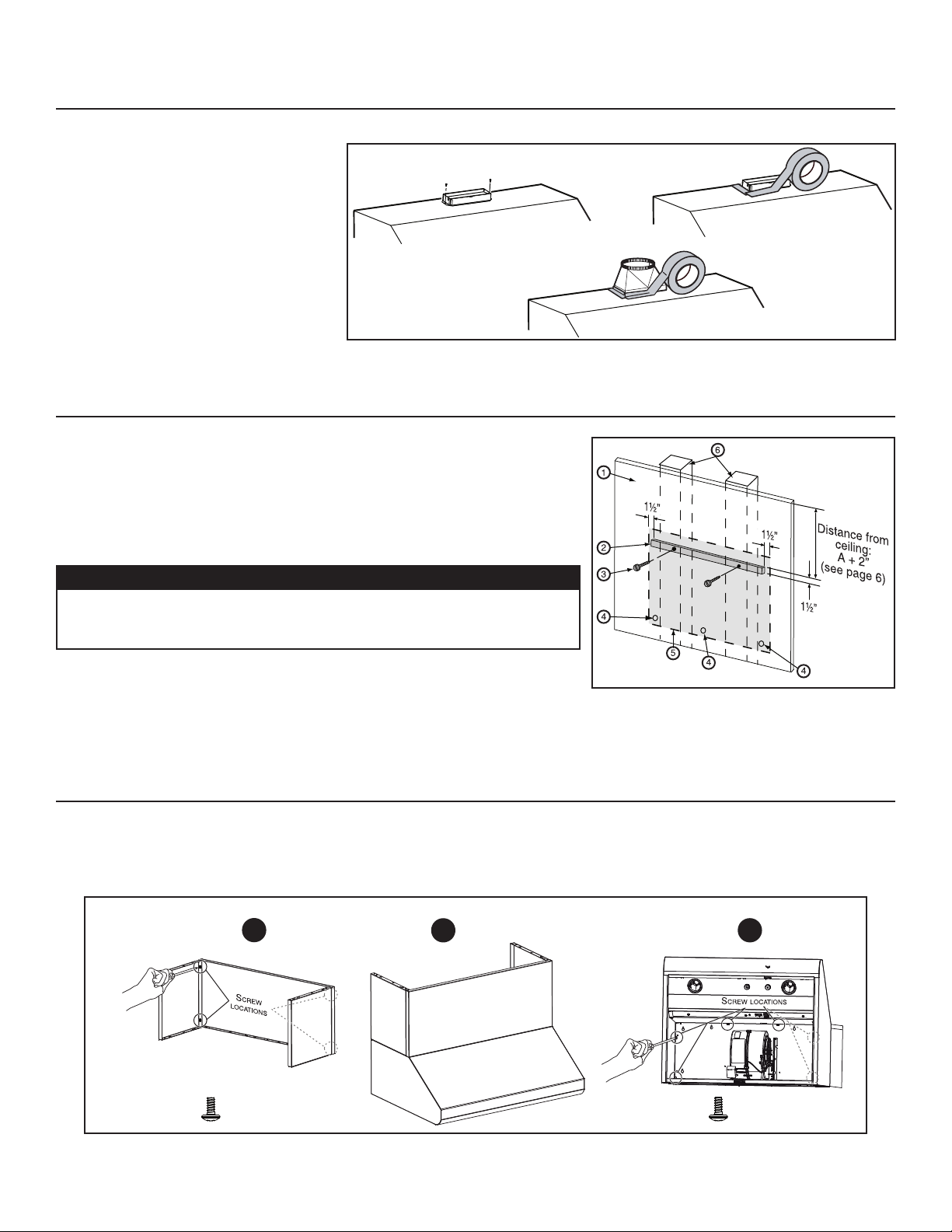
9. INSTALL THE ADAPTER AND THE TRANSITION (IF NEED BE)
(INTERNAL BLOWER(S) HOOD ONLY)
Using standard 3/8" screws provided, secure
the adapter to the top (or back) of the hood
(2 screws for a 3¼" x 10" adapter/damper
and 4 screws for a 4½" x 18½" adapter).
Seal the adapter to the hood using metal
foil duct tape. For round ducting,
install an appropriate sized transition and seal
the joints with metal foil duct tape.
HJ0013
10. INSTALL WOOD MOUNTING STRIP
Measure and mark a level line on wall above cooktop location for the wood
mounting strip (see illustration at right and under step 2). Remove wood mounting strip
from back of hood.Use no. 10 - 2" flat head screws to secure the mounting strip to the
drywall. Make sure to hit the wall studs.
CAUTION
Due to the weight of this hood, ensure that the wood strip is attached to
all of the available studs (2 studs minimum for a 30" width hood, more
as hood width increases); not into the drywall alone.
HD0263A
1. Drywall
2. Wood mounting strip
3. Flat head screw
11. INSTALL AEE OPTIONAL DECORATIVE FLUE COVER
1. Assemble both side panels to the front panel using 4 no. 8 x 3/8" included.
Place the decorative flue cover on top on the range hood.
2.
Secure the decorative flue cover to the top of the range hood using 6 no. 8 x 3/8" included.
3.
1
2
4. Wall anchor location
5. Back of hood outline
6. Wall studs
3
HR0069A
x 4
x 6
10
Page 11
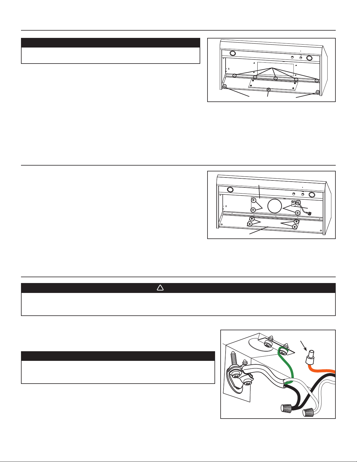
12. INSTALL THE HOOD
!
CAUTION
Hold the hood until it is completely secured to the wood
mounting strip.
MOUNTING SCREWS LOCATION
INTERNAL BLOWER(S) ONLY
Run power cable to installation location. Remove the electrical compartment
cover. Insert the cable in the hood and tighten the wire clamp to secure the cable.
ALL INSTALLATIONS
Rest the back cavity of the hood against the wood mounting strip.
Secure the hood to wood mounting strip with 4 screws no. 8 x 3/4" (for 30" and 36" width hoods) or 6 screws (for 42" and 48" width hoods)
provided at locations shown. Drill three 3/16" sized holes into the drywall for wall anchors through the existing holes in the hood back in the
locations shown. Then, install the three wall anchors with the remaining no. 8 x 3/4" screws and the 3 washers provided.
HD0579
WALL ANCHORS LOCATION
13. ROUGH-IN PLATE LOCATION (EXTERNAL BLOWERS HOODS ONLY)
For ducting through hood top, existing plate remains in place inside the hood
back.
For ducting through hood back, remove existing plate from inside hood back and
remove the rough-in plate from the hood top. Attach the plate to inside hood top
to cover hole. Secure to threaded studs with same 4 nuts. Install the rough-in
plate to hood back so that the wiring box is located on the right side when facing
the hood.
Connect ducting to rough-in plate when installing the rough-in plate. Use metal
foil duct tape to make all joints secure and air-tight.
HD0580
PLATE ON HOOD BACK
ROUGH-IN PLATE
HOOD TOP
ON
LOCKNUTS
LOCKNUTS
WIRING
COVER
14. CONNECT THE WIRING (ALL BLOWERS)
WARNING
Risk of electric shock. Electrical wiring must be done by qualified personnel in accordance with all applicable
codes and standards. Before connecting wires, switch power off at service panel and lock service disconnecting
means to prevent power to be switched on accidentally.
Remove wiring cover from rough-in plate or electrical compartment and set aside.
INTERNAL BLOWERS: Connect cable into wiring box using wire connectors.
Connect BLACK to BLACK, WHITE to WHITE and GREEN
or bare wire under GREEN ground screw.
CAUTION
The ORANGE wire (A) is for make-up air device connection only. If
there is no make-up air device, never remove the cap on the ORANGE
wire end.
Reinstall wiring cover.
A
IN-LINE OR EXTERIOR BLOWERS: See instructions included with blower.
HE0088
11
Page 12
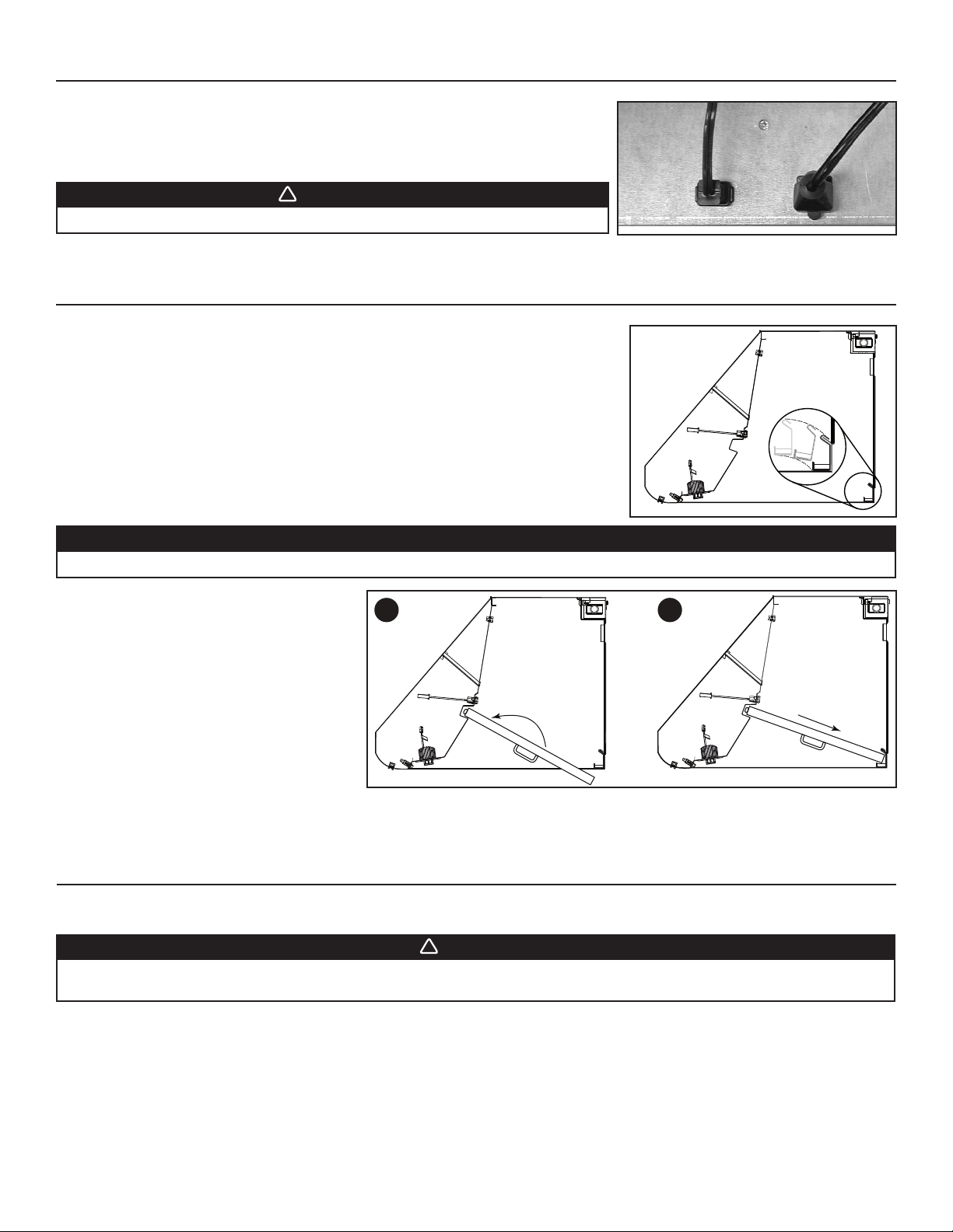
15. INSTALL THE BLOWER (EXTERIOR OR IN-LINE BLOWER)
!
!
Refer to instructions included with blower.
Plug the 3-prong plug cord from rough-in plate to the 3-prong male connector inside the
hood (A) and the 2-prong male connector cord from rough-in plate to the 2-prong plug
inside the hood (B).
WARNING
Do not plug both cords together.
16. REINSTALL GREASE DRIP RAIL AND BAFFLE FILTERS
Reinstall grease drip rail. The illustration at right shows how to reinsert the grease drip rail
into the range hood.
HE0078
HD0654
B
A
CAUTION
Remove protective plastic film covering filters before installing them.
1
It is recommended to install side filters first and
finish with center one(s).
1. Insert one end of the filter into the upper
channel of the hood.
2. Raise the other end toward the inside of hood
and insert in the grease drip rail of the hood.
HD0655
2
17. LED LIGHTING
The lighting of this hood is produced by two LED modules (included).
WARNING
Do not touch lamps during or soon after operation. Burns may occur. Cannot be replaced by any other type of light
bulb or LED module.
12
Page 13
18. USE AND CARE
!
Baffle Filters
The baffle filters should be cleaned frequently. Use a warm detergent solution. Wash often if your cooking style generates a lot of grease—
like frying food or wok cooking.
Remove baffle filters by pushing them towards the back of hood and rotating filters downward. Baffle filters are dishwasher safe. Allow filters
to dry completely before reinstalling them in the hood.
You may clean all-metal filters in the dishwasher using a non-phosphate detergent. Discoloration of the filter may occur if using phosphate
detergent or as a result of local water conditions—but this will not affect filter performance. This discoloration is not covered by the warranty.
Grease Drip Rail
The grease drip rail should be cleaned frequently. Lift it out from the hood and use a warm detergent solution. As for the baffle filters, wash
more often if your cooking style generates a lot of grease—like frying foods or wok cooking. Allow grease drip rail to dry completely before
reinstalling it in the hood.
Hood Cleaning
Stainless steel cleaning:
Do:
• Regularly wash with clean cloth or rag soaked with warm water
and mild soap or liquid dish detergent.
• Always clean in the direction of original polish lines.
• Always rinse well with clear water (2 or 3 times) after cleaning.
Wipe dry completely.
• You may also use a specialized household stainless
steel cleaner.
Don’t:
• Use any steel or stainless steel wool or any other scrapers to
remove stubborn dirt.
• Use any harsh or abrasive cleansers.
• Allow dirt to accumulate.
• Let plaster dust or any other construction residues reach the
hood. During construction/renovation, cover the hood to make
sure no dust sticks to the stainless steel surfaces.
Avoid when choosing a detergent:
• Any cleaners that contain bleach will attack stainless steel.
• Any products containing chloride, fluoride, iodide, bromide or phosphate will deteriorate surfaces rapidly.
• Any combustible products used for cleaning such as acetone, alcohol, ether, benzol, etc., are highly explosive and should never be
used close to a range.
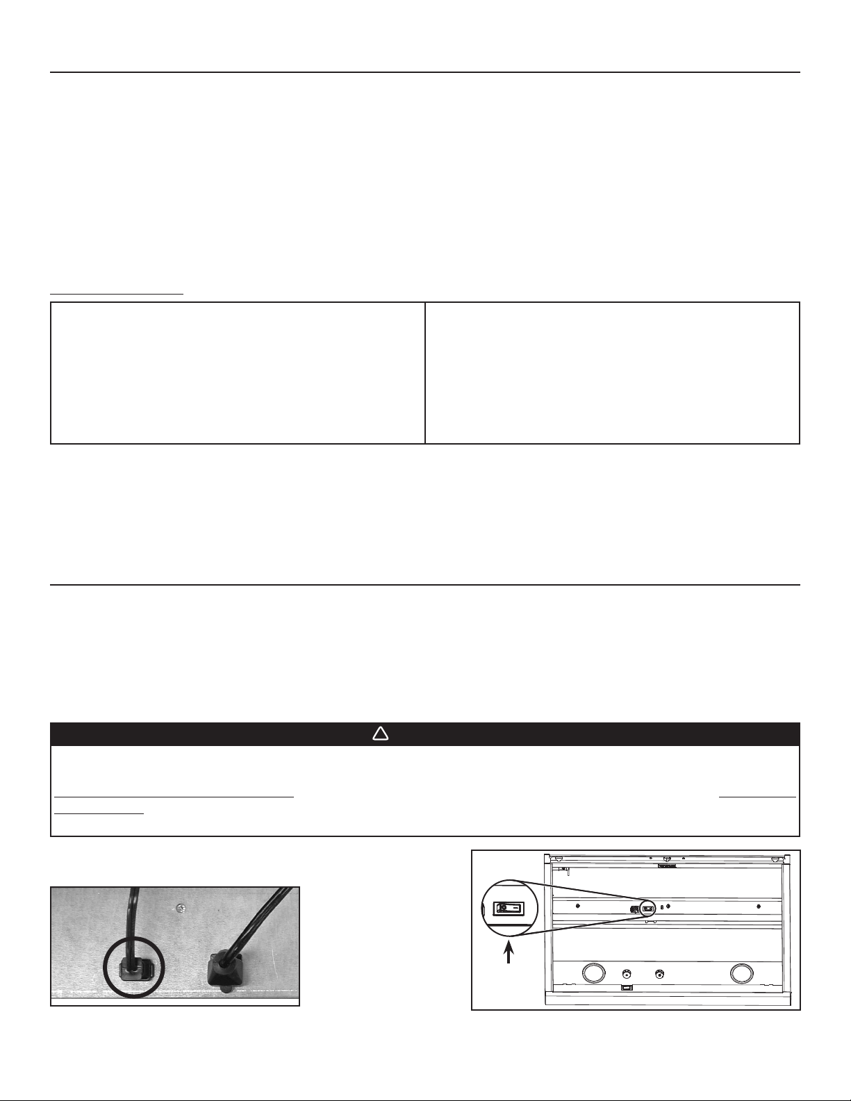
19. OPERATION
Always turn your hood on before you begin cooking to establish an air flow in the kitchen. Let the blower run for a few minutes to clear the
air after you turn off the range. This will help keep the whole kitchen cleaner and brighter.
HEAT SENTRY™
This hood is equipped with a Heat Sentry™ thermostat. This thermostat is a device that will turn the blower on if it senses excessive heat
above the cooking surface.
1) If blower is OFF - it turns blower ON to the last selected speed.
2) If blower is already ON speed will remain the same.
WARNING
The HEAT SENTRY can start the blower during a range top fire or other excessive heat situations even if the hood
is turned off. In this case, it is impossible to turn the blower OFF using control panel buttons. To turn blower OFF:
For exterior or in-line blower hoods, unplug the 2-prong connector cord from inside the hood (C). For internal
blower hoods, set the main power switch (D) (located behind the baffle filters) in OFF position (if it is possible to
do so safely in both cases). If not, do it from the main electrical panel.
When the temperature level drops to normal, the blower will return to its
original setting.
C
HE0078
D
MAIN
POWER SWITCH
HD0449
13
Page 14
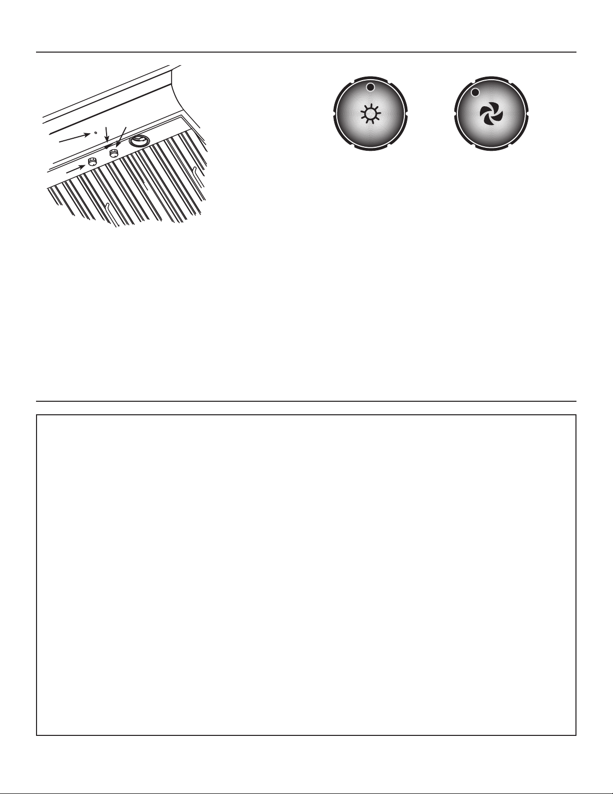
19. OPERATION (CONT'D)
1) LED lighting knob
2) Blower operation indicator
3) ON/OFF blower switch
4) Blower speed control knob
3
4
2
A) LED lighting knob
1
HC0073
HC0035
COOKTOP LIGHTING
The LED lighting of this hood is controled by a rotary dimmer switch (1). The lighting turns on at high intensity, and decreases as the knob
is turned clockwise.
NOTE: When the light switch is turned on, there is a short delay before the lighting turns on; this short delay is normal.
If you experience lighting intensity issues after using the main power switch, cutting the power at service panel, or following a power
outage, turn the lighting to off by rotating the rotary dimmer switch counterclockwise until you hear a clik, and try again.
BLOWER
The blower is operated using two controls.
Use the on/off rocker switch (3) to start and stop the blower. When turned on, the blower indicator (2) turns on and the blower operates at
the previous setting of the speed control (4).
Turn the speed control knob clockwise to increase blower speed – counterclockwise to decrease speed.
AB
B) Blower speed control knob
20. WARRANTY
ONE YEAR LIMITED WARRANTY FOR BROAN ELITE PRODUCTS
Venmar Ventilation ULC warrants to the original consumer purchaser of Broan Elite products that such products will be free from defects
in materials or workmanship for a period of one year from the date of original purchase. LED modules and LED driver are also covered
by this warranty for a period of one (1) year. THERE ARE NO OTHER WARRANTIES, EXPRESS OR IMPLIED, INCLUDING, BUT NOT
LIMITED TO, IMPLIED WARRANTIES OR MERCHANTABILITY OR FITNESS FOR A PARTICULAR PURPOSE.
During this one-year period, Venmar Ventilation ULC will, at its option, repair or replace, without charge, any product or part which is
found to be defective under normal use and service.
THIS WARRANTY DOES NOT EXTEND TO FLUORESCENT LAMP STARTERS, TUBES, HALOGEN AND INCANDESCENT BULBS,
FUSE, FILTERS, DUCTS, ROOF CAPS, WALL CAPS AND OTHER ACCESSORIES FOR DUCTING. This warranty does not cover
(a) normal maintenance and service or (b) any products or parts which have been subject to misuse, negligence, accident, improper
maintenance or repair (other than by Venmar Ventilation ULC), faulty installation or installation contrary to recommended installation
instructions.
Warranty service is to be completed by an authorized Service Center designated by Venmar Ventilation ULC. Where applicable, inhome service will be made available only in areas where a contracted service provider offers service. If in-home service is not available,
the product will be repaired or replaced, at Venmar Ventilation ULC's discretion, by the nearest authorized service provider. The unit
removal and reinstallation works are under the customer responsibility, and Venmar Ventilation ULC cannot be charged for them.
The duration of any implied warranty is limited to the one-year period as specified for the express warranty. Some provinces do not allow
limitation on how long an implied warranty lasts, so the above limitation may not apply to you.
VENMAR VENTILATION ULC’S OBLIGATION TO REPAIR OR REPLACE, AT VENMAR VENTILATION ULC’S OPTION, SHALL BE
THE PURCHASER’S SOLE AND EXCLUSIVE REMEDY UNDER THIS WARRANTY. VENMAR VENTILATION ULC SHALL NOT BE
LIABLE FOR INCIDENTAL, CONSEQUENTIAL OR SPECIAL DAMAGES ARISING OUT OF OR IN CONNECTION WITH PRODUCT
USE OR PERFORMANCE. Some provinces do not allow the exclusion or limitation of incidental or consequential damages, so
the above limitation or exclusion may not apply to you.
This warranty gives you specific legal rights, and you may also have other rights, which vary from one province to another. This warranty
supersedes all prior warranties.
To qualify for warranty service, you must (a) notify Venmar Ventilation ULC at the address or telephone number stated below, (b) give
the model number and part identification and (c) describe the nature of any defect in the product or part. At the time of requesting
warranty service, you must present evidence of the original purchase date.
Venmar Ventilation ULC, 550 Lemire blvd. Drummondville, QC J2C 7W9 www.broan.ca 1-877-896-1119
14
Page 15
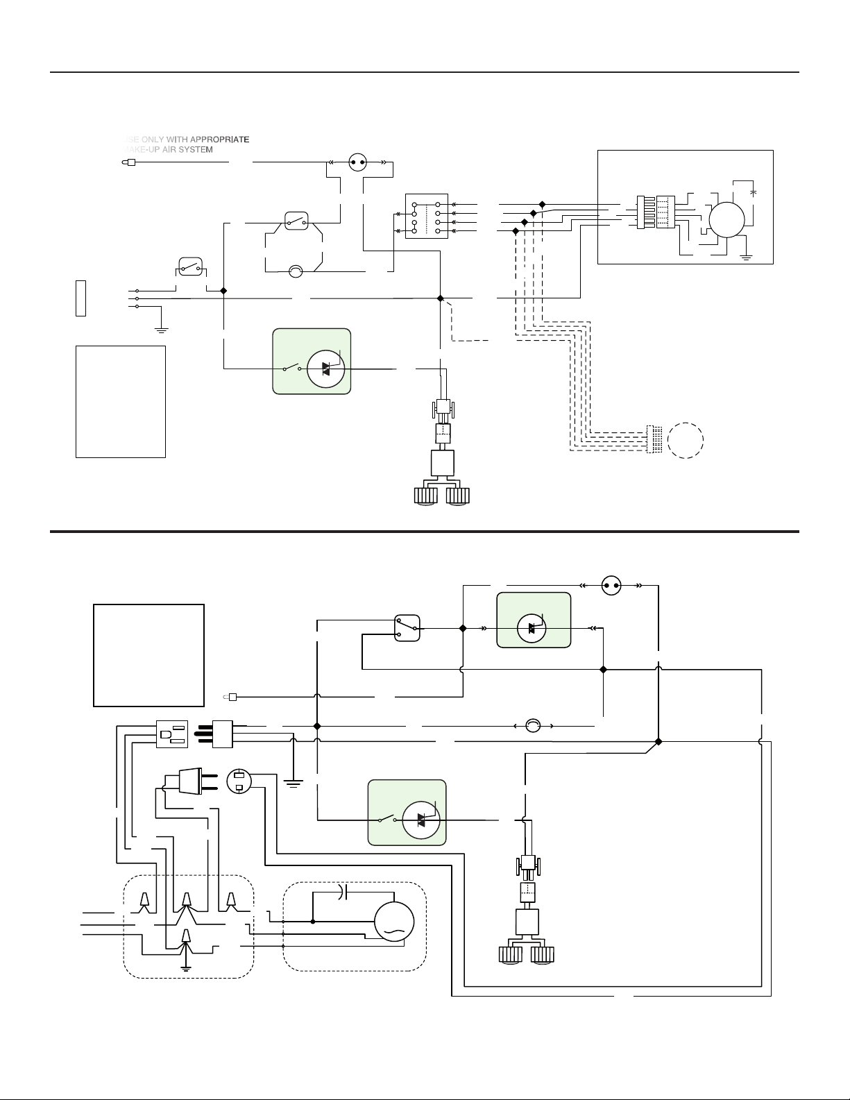
21. WIRING DIAGRAMS
Broan Elite E60000LC Series
Internal blower(s) hoods
USE ONLY WITH APPROPRIATE
MAKE-UP AIR SYSTEM
LINE
NEUTRAL
GROUND
120 VAC
COLOR CODE
BLK BLACK
BLU BLUE
BRN BROWN
GRY GREY
ORG ORANGE
RED RED
WHT WHITE
YEL YELLOW
HE0207A
MAIN SWITCH
BLK
BLK
BLK
GRY
ORA
BLK
FAN SWITCH
RED
THERMOSTAT
LED CONTROL
IN J1
WHT
RED
NEON
ORA ORA
J2 OUT
GRY
GRY
YEL
9408
AAAA
B
LED
WHT
LED
RIVER
D
BLOWER MOTOR
GRY
BLK
WHT
ORA
RED
BLU
BRN
M
1
BLU
2
WHT
3
ORA
4
BLK
BLU
WHT
ORA
BLK
ORA
WHT
WHT
BLU
BLK
WHT
WHT
OPTIONAL SECOND
BLOWER MOTOR
M
LED
Broan Elite E60000LC Series
Exterior or In-Line blower hoods
COLOR CODE
BLK BLACK
BLU BLUE
GRN GREEN
ORA ORANGE
WHT WHITE
YEL YELLOW
GRY GREY
BLK
WHT
GRN
120 V
SUPPLY
LINE
BLK
RETURN
GROUND
USE ONLY WITH
APPROPRIATE
MAKE-UP AIR SYSTEM
BLK
WHT
WHTWHT
GRN
BLK
BLK
BLK
GRY
FAN
SWITCH
On 3
Off 2
ORA
LED CONTROL
IN J1
M
BLU
NEON
BLK
SPEED CONTROL
1
ORA
HEAT SENTRY
THERMOSTAT
BLU
BLK
WHT
WHT
J2 OUT
YEL
LED
RIVER
D
HE0208A
ROUGH-IN PLATE
REMOTE
BLOWER ASSEMBLY
15
LED
LED
WHT
Page 16
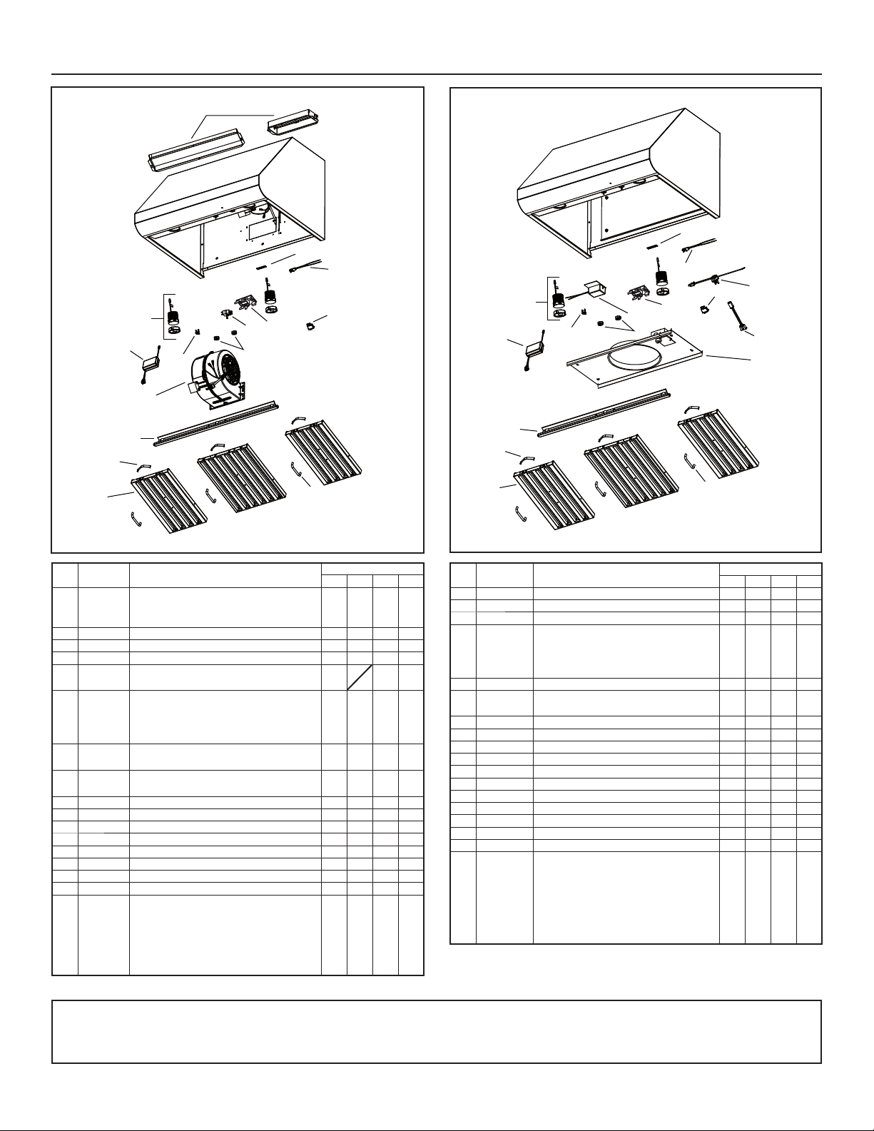
22. SERVICE PARTS
Broan Elite E60000LC
Single or double
internal blower hoods
2
3
5
6
7
8
1
Series Exterior or In-Line
blower hoods
15
15
Broan Elite E60000LC
14
12
11
4
10
13
3
4
2
11
10
12
14
13
18
17
16
6
7
9
8
9
HL0236
KEY
NO
1
PART
.
SV13296
SV17797
NO
.
DESCRIPTION
ADAPTER/DAMPER 3¼" X 10"
(1-BLOWER HOOD)
ADAPTER 4½" X 18½" (2-BLOWER HOOD)1-11-1-1
QTY. (HOOD WIDTH)
30" 36" 42" 48"
2 62612 LED MODULE (1) 2222
3 62248 LED DRIVER AND CONNECTOR HARNESS 1111
4 SV03435 HEAT SENTRYTM THERMOSTAT 1111
5 SV08582 INTERNAL MOTOR 1
SV17640
SV17641
6
SV17642
SV17643
7 SV08337 B
SV17606
8
SV17609
9 SV07680 B
REASE RAIL 30"
G
GREASE RAIL 36"
GREASE RAIL 42"
GREASE RAIL 48"
AFFLE FILTER SPRING (SET OF 6) 1111
AFFLE FILTER 8.84" x 15.125"
B
B
AFFLE FILTER 11.84" X 15.125"
AFFLE FILTER HANDLE WITH SCREWS 3344
1
22
2
1
-
-
-
-
-
1
-
-
1
-
-
21-322-
-
-
-
1
4
10 SV08355 BLOWER AND LIGHT KNOBS (2 KNOBS) 1111
11 SV21722 S
12 SV21248 L
PEED CONTROL 1111
IGHT CONTROL WITH NUT 1111
13 SV08339 BLOWER ROCKER SWITCH 1111
14 SV08093 PILOT LAMP ASS'Y 1111
15 SV06750 BROAN ELITE LOGO 1111
* SV21241 INSTALLATION GUIDE 1111
PARTS BAG: 2 WIRE CONNECTORS,
1 WIRE CLAMP, 3 WALL ANCHORS,
3 WASHERS 13/64" ID X 3/4" OD,
* SV08352
4 SCREWS NO. 8 X 3/8",
1111
8 SCREWS NO. 8 X 3/4",
8 MECHANICAL SCREWS NO. 8-32 X 1/4",
HL0237
KEY
PART
.
NO
.
NO
2 62612 LED
DESCRIPTION
MODULE (1) 2222
QTY. (HOOD WIDTH)
30" 36" 42" 48"
3 62248 LED DRIVER AND CONNECTOR HARNESS 1111
4 SV03435 HEAT SENTRYTM THERMOSTAT 1111
6
SV17640
SV17641
SV17642
SV17643
GREASE RAIL 30"
GREASE RAIL 36"
GREASE RAIL 42"
GREASE RAIL 48"
1
-
-
-
-
-
1
-
-
1
-
-
7 SV08337 BAFFLE FILTER SPRING (SET OF 6) 1111
8
SV17606
SV17609
BAFFLE FILTER 8.84" x 15.125"
BAFFLE FILTER 11.84" X 15.125
21-322-
9 SV07680 BAFFLE FILTER HANDLE WITH SCREWS 3344
10 SV08355 BLOWER AND LIGHT KNOBS (2 KNOBS) 1111
11 SV03501 SPEED CONTROL 1111
12 SV21248 L
IGHT CONTROL WITH NUT 1111
13 SV08339 BLOWER ROCKER SWITCH 1111
14 SV08093 PILOT LAMP ASS'Y 1111
15 SV06750 BROAN ELITE LOGO 1111
16 SV08354 ROUGH-IN PLATE 10" ROUND 1111
17 SV13923 FEMALE CONNECTOR 1111
18 SV13924 M
* SV21241 I
ALE CONNECTOR 1111
NSTALLATION GUIDE 1111
PARTS BAG: 2 WIRE CONNECTORS,
1 WIRE CLAMP, 3 WALL ANCHORS,
3 WASHERS 13/64" ID X 3/4" OD,
* SV08352
4 SCREWS NO. 8 X 3/8",
8 S
CREWS NO. 8 X 3/4",
ECHANICAL SCREWS
8 M
NO. 8-32 X 1/4",
1111
4 FLAT HEAD SCREWS NO. 10-2"
* NOT SHOWN.
4 FLAT HEAD SCREWS NO. 10-2"
* NOT SHOWN.
REPLACEMENT PARTS AND REPAIRS
In order to ensure your unit remains in good working condition, you must use Venmar Ventilation ULC genuine replacement parts only. Venmar Ventilation ULC genuine replacement parts are
specially designed for each unit and are manufactured to comply with all the applicable certification standards and maintain a high standard of safety. Any third party replacement
part used may cause serious damage and drasticallyreduce the performance level of your unit, which will result in premature failing. Venmar Ventilation ULC recommends to
contact a certified service depot for all replacement parts and repairs.
-
-
-
1
4
16
 Loading...