

Page 1
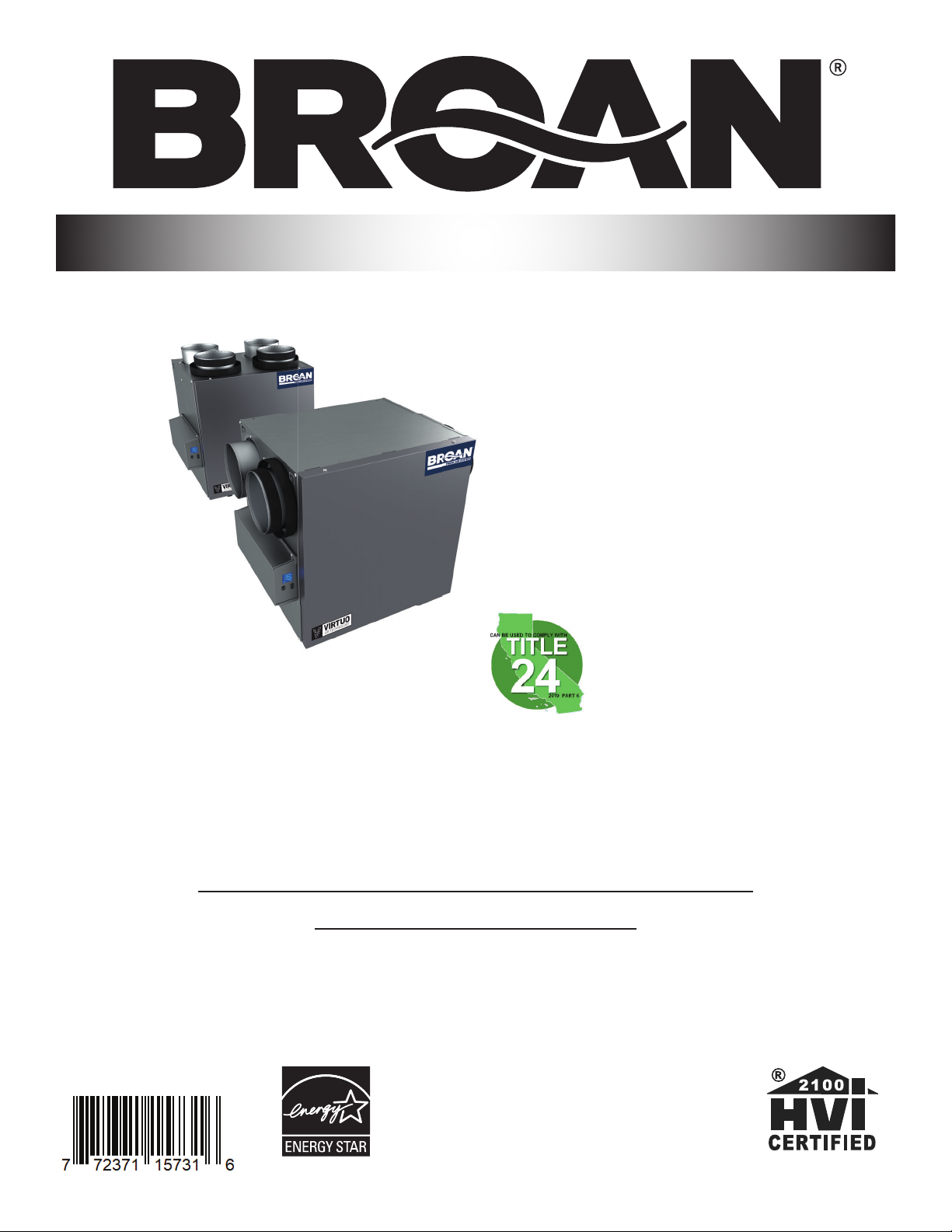
VB0288
USER AND INSTALLER MANUAL
B110H65RT* B110H65RS*
B130H65RT* B130H65RS*
B130E65RT B130E65RS
B150H75NT* B150H75NS*
B160H75RT* B160H75RS*
B160H65RT* B160H65RS*
B160E65RT B160E65RS
REGISTER YOUR PRODUCT ONLINE AT:
www.broan-nutone.com/en-us/home/customer-service/product-registration
For additional information, visit www.Broan-NuTone.com
INSTALLER: READ THESE INSTRUCTIONS
SAVE THEM FOR USER
RESIDENTIAL USE ONLY
*THESE PRODUCTS EARNED THE ENERGY
STAR® BY MEETING STRICT ENERGY EFFICIENCY
GUIDELINES SET BY NATURAL RESOURCES
CANADA AND THE US EPA. THEY MEET
ENERGY STAR REQUIREMENTS ONLY WHEN
USED IN CANADA.
23832 REV. 07
Page 2

Please take note that this manual uses the following symbols to emphasize particular information:
⚠ WARNING
Identifi es an instruction which, if not followed, might cause serious personal injuries including possibility of death.
CAUTION
Denotes an instruction which, if not followed, may severely damage the unit and/or its components.
NOTE: Indicates supplementary information needed to fully complete an instruction.
LIMITATION
For residential (domestic) installation only. Installation work and electrical wiring must be done by a qualifi ed person in accordance with
all applicable codes and standards, including fi re-rated construction codes and standards.
⚠ WARNING
TO REDUCE THE RISK OF FIRE, ELECTRIC SHOCK, OR INJURY TO PERSON(S) OBSERVE THE FOLLOWING:
1. Use this unit only in the manner intended by the manufacturer.
2. Before servicing or cleaning this unit, disconnect power cord from electrical outlet.
3. This unit is not designed to provide combustion and/or dilution air for fuel-burning appliances.
4. When cutting or drilling into a wall or ceiling, do not damage electrical wiring and other hidden utilities.
5. Do not use this unit with any solid-state speed control device other than those specifi ed in section 3.1.
6. This unit must be grounded. The power supply cord has a 3-prong grounding plug for your personal safety. It must be plugged into
a mating 3-prong grounding receptacle, grounded in accordance with the national electrical code and local codes and ordinances.
Do not remove the ground prong. Do not use an extension cord.
7. Do not install in a cooking area or connect directly to any appliances.
8. Do not use to exhaust hazardous or explosive materials and vapors.
9. When performing installation, servicing or cleaning this unit, it is recommended to wear safety glasses and gloves.
10. When applicable local regulation comprises more restrictive installation and/or certifi cation requirements, the aforementioned
requirements prevail on those of this document and the installer agrees to conform to these at his own expense.
CAUTION
1. To avoid prematurely clogged fi lters, turn the unit OFF during construction or renovation.
2. Please read specifi cation label on product for further information and requirements.
3. Be sure to duct air outside – Do not intake/exhaust air into spaces within walls or ceiling or into attics, crawl spaces, or garage. Do
not attempt to recover the exhaust air from a dryer or a range hood.
4. Intended for residential installation only in accordance with the requirements of NFPA 90B (for a unit installed in U.S.A.) or Part 9 of
the National Building Code of Canada (for a unit installed in Canada).
5. Do not run any air ducts directly above or within 2 ft. of a furnace or its supply plenum, boiler, or other heat producing appliance. If
a duct has to be connected to the furnace return plenum, it must be connected 10 ft. away from plenum connection to the furnace.
6. The ductwork is intended to be installed in compliance with all applicable local and national codes.
7. When leaving the house for a long period of time (more than two weeks), a responsible person should regularly check if the unit
operates adequately.
8. If the ductwork passes through an unconditioned space (e.g.: attic), the unit must operate continuously except when performing
maintenance and/or repair. Also, the ambient temperature of the house should never drop below 65°F (18°C).
9. At least once a year, the unit mechanical and electronic parts should be inspected by qualifi ed service personnel.
10. Do not use your unit during construction or renovation of your house or when sanding drywall. Certain types of dust and vapors may
damage your system.
11. Make sure at all times that the outside intake and exhaust hoods are free from any snow during the winter season. It is important to
check your unit during a big snow storm, so it doesn’t draw in any snow. If this is the case, please turn the unit OFF for a few hours.
12. Since the electronic control system of the unit uses a microprocessor, it may not operate correctly because of external noise or very
short power failure. If this happens, unplug the unit and wait approximately 10 seconds. Then, plug the unit in again.
13. Do not make excessive use of fragrance appliances or chemicals since some may damage the unit components material.
2
Page 3

TABLE OF CONTENTS
1. TECHNICAL DATA ...................................................................................................................... 4
1.1 AIR DISTRIBUTION (NORMAL OPERATION) ...............................................................................................................4
2. INSTALLATION .................................................................................................................................... 4
2.1 LOCATING AND MOUNTING THE UNIT.....................................................................................................................4
2.2 INSTALLING THE DUCTWORK AND THE REGISTERS ...............................................................................................6
2.2.1 FULLY DUCTED SYSTEM (T-1) ........................................................................................................................................... 6
2.2.2 EXHAUST DUCTED SYSTEM (T-2) ......................................................................................................................................6
2.2.3 SIMPLIFIED INSTALLATION (T-4) .........................................................................................................................................7
2.3 CONNECTING THE DRAIN (HRV ONLY) ......................................................................................................................8
2.4 INSTALLING DUAL EXTERIOR HOOD USING TANDEM® TRANSITION KIT (OPTIONAL) .....................................9
2.5 INSTALLING THE EXTERIOR HOODS ..........................................................................................................................9
2.6 CONNECTING THE DUCTS TO THE UNIT..................................................................................................................9
2.6.1 DUCTS CONNECTION ....................................................................................................................................................10
3. CONNECTIONS ................................................................................................................................11
3.1 ELECTRICAL CONNECTION TO OPTIONAL MAIN WALL CONTROL ..................................................................11
3.1.1 ELECTRICAL CONNECTION TO SPEED, DEHUMIDISTAT OR AUTOMATIC OPTIONAL MAIN WALL CONTROL ..................................11
3.1.2 ELECTRICAL CONNECTION TO ADVANCED OPTIONAL MAIN WALL CONTROL .......................................................................11
3.2 ELECTRICAL CONNECTION TO OPTIONAL AUXILIARY WALL CONTROL ..........................................................12
3.2.1 ELECTRICAL CONNECTION TO 20-40-60 OPTIONAL AUXILIARY WALL CONTROL ...................................................................12
3.3 CONNECTION TO THE CENTRAL FORCED-AIR SYSTEM ......................................................................................12
3.3.1 UNIT OPERATION USING A CENTRAL FORCED-AIR SYSTEM THERMOSTAT ...............................................................................12
3.3.2 UNIT INTERCONNECTION WITH CENTRAL FORCED-AIR SYSTEM (R, C, G, GF) ....................................................................... 12
3.3.3 SYNCHRONIZATION WITH CENTRAL FORCED-AIR SYSTEM FUNCTION .....................................................................................12
4. WIRING DIAGRAM ...........................................................................................................................13
5. UNIT AUTO-BALANCING ................................................................................................................ 14
6. USING THIS UNIT .............................................................................................................................14
6.1 YOUR VENTILATION SYSTEM .....................................................................................................................................14
6.2 INTEGRATED CONTROL .............................................................................................................................................14
7. SERVICE PARTS ................................................................................................................................. 15
8. INSTALLER’S TROUBLESHOOTING ...............................................................................................17
9. MAINTENANCE ................................................................................................................................ 20
9.1 QUARTERLY ...................................................................................................................................................................20
9.2 ANNUAL (AT FALL) .......................................................................................................................................................21
10. USER’S TROUBLESHOOTING ....................................................................................................... 21
11. WARRANTY ..................................................................................................................................... 22
3
Page 4
Consumer Information
A. To ensure quiet operation of the ENERGY STAR certifi ed H/ERV, each product model must be installed using sound attenuation
techniques appropriate for the installation.
B. The way your heat/energy-recovery ventilator is installed can make a signifi cant difference to the electrical energy you use. To
minimize the electricity use of the heat/energy-recovery ventilator, a stand-alone fully ducted installation is recommended. If you
choose a simplifi ed installation that operates your furnace air handler for room-to-room ventilation, an electrically effi cient furnace that
has an electronically commutated (EC) variable speed blower motor will minimize your electrical energy consumption and operating
cost.
C. Installation of a user-accessible control with your product model will improve comfort and may signifi cantly reduce the product
model’s energy use.
1. TECHNICAL DATA
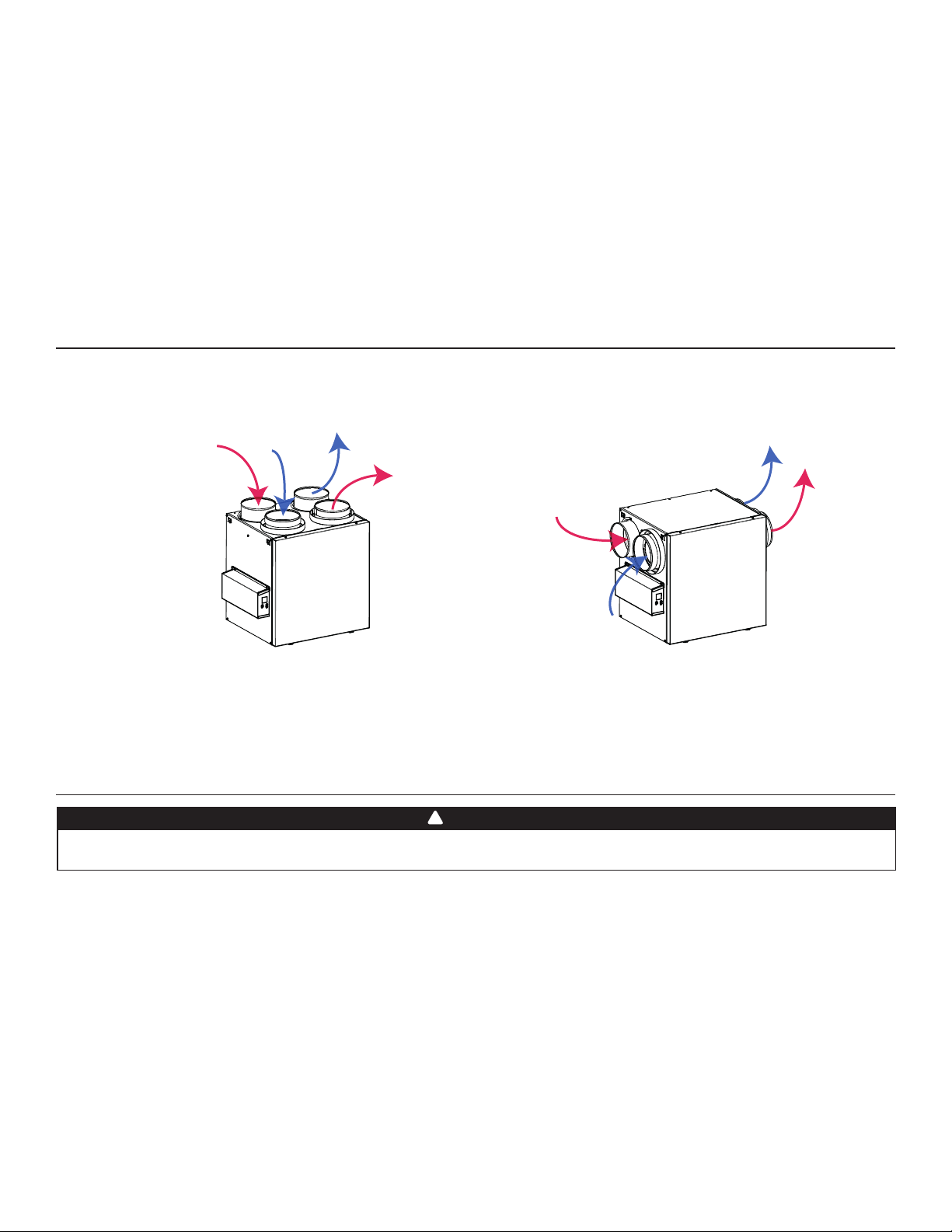
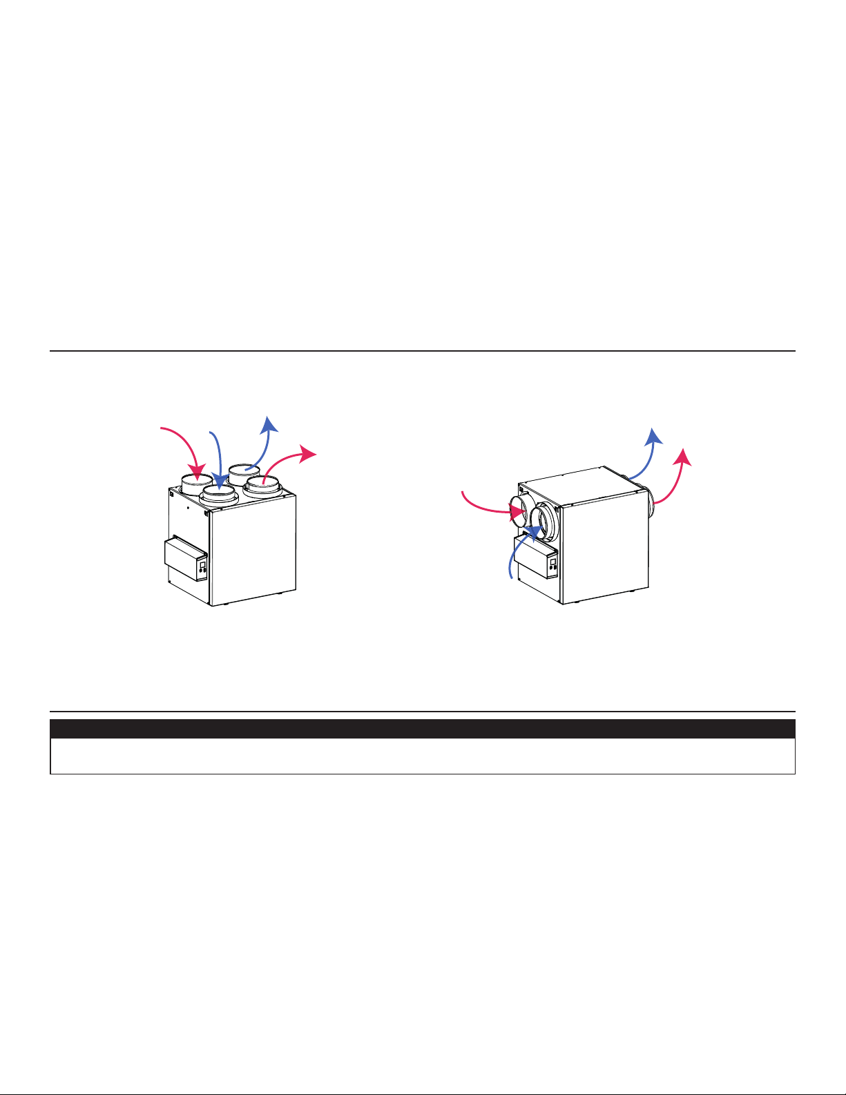
1.1 AIR DISTRIBUTION (NORMAL OPERATION)
VF0077
Stale
air from
building
Fresh
air from
outdoors
Fresh air to
building
Stale air to
outdoors
Stale
air from
building
Fresh air to
building
Stale air to
outdoors
Fresh
air from
outdoors
NOTE: The dimensions, performance charts, defrost cycle tables and specifi cations are listed on the specifi cation sheets of the unit.
Visit our website at www.Broan-NuTone.com.
2. INSTALLATION
!
WARNING
The wearing of safety glasses and gloves is recommended when installing, maintaining or cleaning the unit to reduce the
risk of injury that could be caused by the presence of thin metal and/or high moving parts.
2.1 LOCATING AND MOUNTING THE UNIT
Choose an appropriate location for the unit:
• Within an area of the house where the ambient temperature is kept between 50°F and 140°F;
• Away from living areas (dining room, living room, bedroom), if possible;
• So as to provide easy access to the interior cabinet for maintenance, and to the control panel on the side of the unit;
• Close to an exterior wall, so as to limit the length of the insulated fl exible ducts to and from the unit;
• HRV units only: close to a drain. If no drain is close by, use a pail to collect run-off;
• Away from hot chimneys, electrical panel and other fi re hazards;
• Within 6 feet of a power source (standard outlet).
4
Page 5
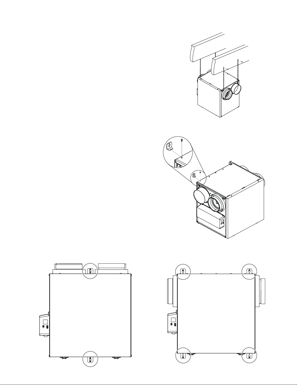
2.1 LOCATING AND MOUNTING THE UNIT (CONT.)
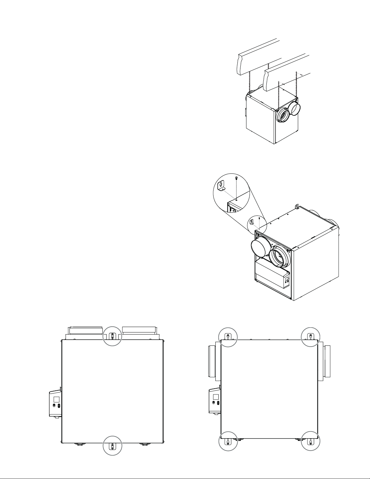
Suspended to the joists or trusts:
• Slightly bend the brackets on the unit to insert the provided
chains.
• Hang the unit to the joists (or trusts) using the chains. Springs are
not required.
• Always make sure that the unit is no more than 1/4" off level.
OR
Wall mounted:
• Choose the appropriate location(s) for the mounting brackets
(see illustration below) according to stud(s) position.
• Insert the provided brackets under the unit frame (see illustration
hereafter).
• Fix the bracket using the screw no. 8 x 3/8".
• Using the 4 no. 8 x 1½" screws provided, secure the unit to the
wall making sure that the 4 screws engage into a stud.
• Always make sure that the unit is no more than 1/4" off level.
VD0485
INSTALLATION WITH 2 BRACKETS INSTALLATION WITH 4 BRACKETS
VD0486
VD0487
5
Page 6
2.2 INSTALLING THE DUCTWORK AND THE REGISTERS
!
WARNING
Never install a stale air exhaust register in a room where there is a combustion device, such as a furnace, gas water
heater, fi replace or any appliance or equipment that can generate gaseous contaminants, or pollutants. The negative
pressure this could create in the room may impair proper evacuation of the gas or pollutants, which may have severe health
consequences.
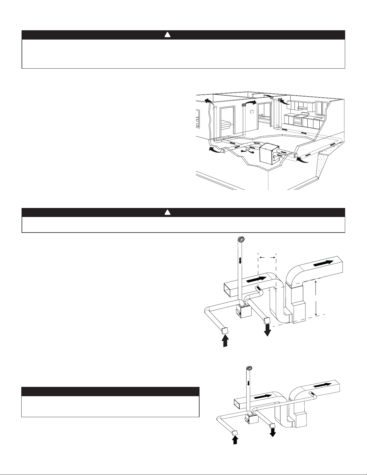
2.2.1 FULLY DUCTED SYSTEM (T- 1 )
STALE AIR EXHAUST DUCTWORK:
• Install registers in areas where contaminants and humidity are
produced: kitchen, bathrooms, laundry room, etc.
• Install registers on an interior wall, 6 to 12 inches away from the
ceiling OR in the ceiling.
• Install the kitchen register at least 4 feet away from the range.
• Bathroom fans and range hoods can be used to better exhaust stale
air.
• Homes with more than one level require at least one exhaust register
at the highest level.
FRESH AIR DISTRIBUTION DUCTWORK:
• Install registers in bedrooms, dining room, living room and
basement.
• Install registers in the ceiling OR high on the walls with the airfl ow
directed towards the ceiling.
• If a register must be installed in the fl oor, direct the airfl ow up the
wall.
NOTE: For this type of con guration, the T-1 option must be selected on the LCD screen when auto-balancing the unit.
2.2.2 EXHAUST DUCTED SYSTEM (T- 2)
!
WARNING
Duct connection to the central forced-air system can be regulated by some codes and standards. It is your responsibility
to consider and comply with your local requirements to avoid any non-compliance.
STALE AIR EXHAUST DUCTWORK:
Same as for Fully Ducted System, described on point 2.2.1.
FRESH AIR DISTRIBUTION:
• Connect the fresh air distribution duct of the unit to the central forced-
air system return duct at least 10 feet away from the central forced-air
system (A+B)*.
* This 10-ft. distance applies only in areas where the outside temperature
falls below the freezing point (32°F).
NOTE: The central forced-air system blower operation can be synchronized
with the unit (see Section 3.3). It is recommended, but not essential that the
central forced-air system blower runs when the unit is in operation.
Stale air from
bathroom
A
Fresh air to
building
B
NOTE: For this type of con guration, the T-2 option must be selected
on the LCD screen when auto-balancing the unit.
ALTERNATE INSTALLATION (T- 3 ):
Unit should be synchronized with central forced-air system operation
to avoid condensation and mold growth in central forced-air system
distribution ducting if cooling mode of central forced-air system is used.
CAUTION
This confi guration is not recommended with high velocity central
forced-air system. High pressures produced by these systems
could affect unit proper operation and generate errors.
NOTE: For this type of con guration, the T-3 option must be selected
on the LCD screen when auto-balancing the unit.
6
VH0165
VH0166
Fresh air from
outdoors
Fresh air from
outdoors
Stale air to
outdoors
Stale air from
bathroom
Stale air to
outdoors
A+B= MIN 10’
Fresh air to
building
Page 7
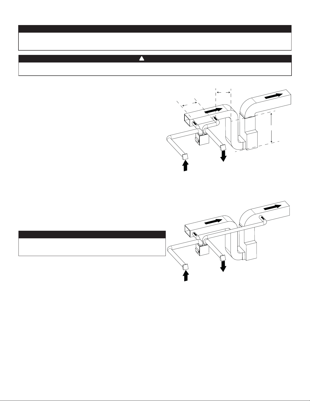
2.2.3 SIMPLIFIED INSTALLATION (T- 4)
CAUTION
The central forced-air system must be synchronized with the unit since fresh air evacuation and distribution come from the
same section. The central forced-air system must operate to avoid fresh air to be directly drawn by the evacuation, which
would reduce signifi cantly fresh air supply to the building. See Section 3.3 for ducting.
!
WARNING
Duct connection to the central forced-air system can be regulated by some codes and standards. It is your responsibility
to consider and comply with your local requirements to avoid any non-compliance.
Fresh air and exhaust air fl ow through the central forced-air system ducts,
which simplifi es the installation.
The use of bathroom fans and a range hood is suggested to exhaust stale
air.
STALE AIR EXHAUST DUCTWORK:
Connect the stale air intake port of the unit to the central forced-air
system return duct at least 3 feet ahead of the fresh air distribution from
the unit.
FRESH AIR DISTRIBUTION:
Connect the fresh air distribution duct of the unit to the central forcedair system return duct at least 10 feet away from the central forced-air
system (A+B)*.
* This 10-ft. distance applies only in areas where the outside temperature
falls below the freezing point (32°F).
NOTE: For this type of con guration, the T-4 option must be
selected on the LCD screen when auto-balancing the unit.
C
Stale air from
building
Fresh air from
outdoors
VH0167
A
Fresh air to
building
B
Stale air to
outdoors
A+B= MIN 10’
C=3’
ALTERNATE INSTALLATION (T- 5 ):
Unit should be synchronized with central forced-air system operation
to avoid condensation and mold growth in central forced-air system
distribution ducting if cooling mode of central forced-air system is used.
CAUTION
This confi guration is not recommended with high velocity central
forced-air system. High pressures produced by these systems
could affect unit proper operation and generate errors.
NOTE: For this type of con guration, the T-5 option must be
selected on the LCD screen when auto-balancing the unit.
Fresh air to
building
Stale air from
building
Stale air to
outdoors
Fresh air from
outdoors
VH0168
7
Page 8
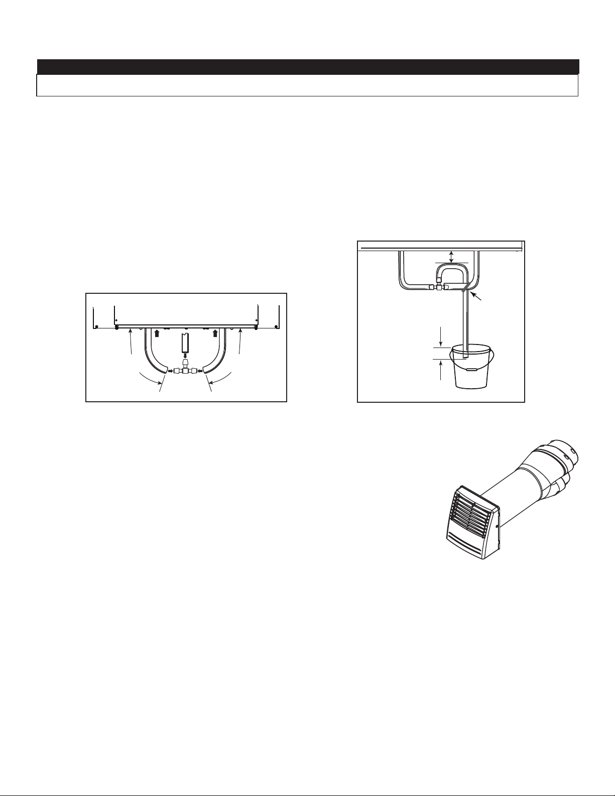
2.3 CONNECTING THE DRAIN (HRV ONLY)
CAUTION
Install the drain hose included and run it to a drain or a pail. This unit may generate a large amount of water in cooler
weather. It is necessary to install the drain hose properly to prevent water damage and/or material damage.
• Cut the appropriate length of drain tubing (see illustrations below).
• Connect the tubing to the provided adaptor.
• Make a water trap loop in the tube to prevent the unit from drawing unpleasant odors from the drain source.
• Add water in the loop to prevent noise or hiss.
• Make sure there is a distance of at least 2" between the unit and the tubing loop (see illustration below).
• Using the tie wrap provided, attach the tubing as illustrated below.
• Run the tube to the fl oor drain or to an alternate drain pipe or pail.
• IMPORTANT: If using a pail to collect water, place the tube end approximately 1” inside the pail in order to prevent water from being
drawn back up into the unit.
≥ 2”
TIE WRAP
± 1”
VO0290A
13"
(330 mm)
13"
(330 mm)
VO0083
2.4 INSTALLING DUAL EXTERIOR HOOD USING TANDEM® TRANSITION KIT (OPTIONAL)
For units set at 110 CFM or less, a Tandem transition kit can be used instead of 2 exterior hoods;
but take into account this device will generate approximately an additional 0.2 in w.g. static pressure
depending on the installation.
The minimum joist opening needed to install the Tandem
the Tandem transition is 8¾”.
To connect the insulated fl exible ducts to the Tandem transition (Exhaust air to outdoors and Fresh air
from outdoors), follow the instructions included with the Tandem transition kit (part no.VTYIK1).
®
transition is 9¾”. The maximum height of
VR0003
8
Page 9
V
2.5 INSTALLING THE EXTERIOR HOODS
Choose an appropriate location for the exterior hoods:
• At least 6 feet between both hoods to avoid cross-contamination
• At least 18 inches away from the ground
!
WARNING
Make sure intake hood is at least 6 feet (1.8 m) away from any of the
following:
• Dryer exhaust, high effi ciency central forced-air system vent, central
vacuum vent
• Gas meter exhaust, gas barbecue-grill
• Any exhaust from a combustion source
• Garbage bin and any other source of contamination.
Ignoring these recommendations could signifi cantly degrade the
quality of the incoming air which, in some cases, could result in health
consequences.
In the event of a confl ict between our conditions and local requirements,
the latter will have priority.
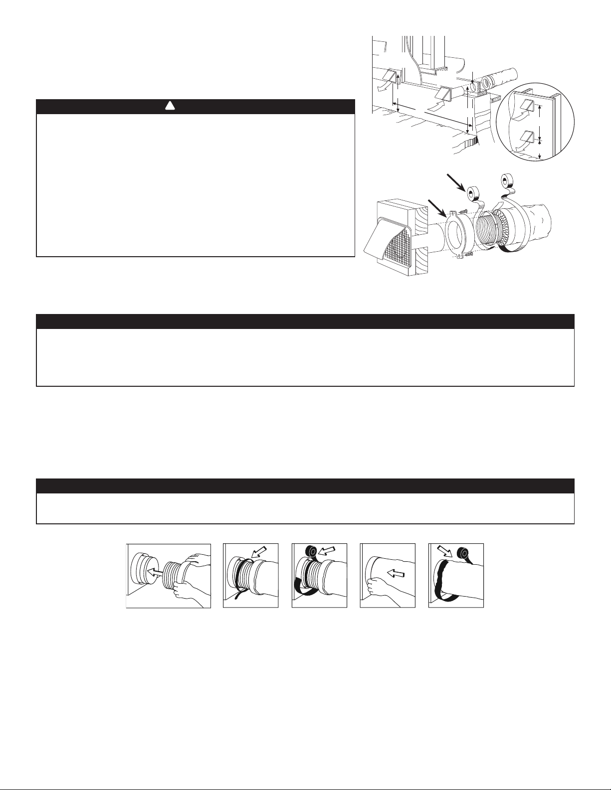
Refer to illustration at right for proper connection method of the insulated ducts
to the hoods. An “Anti-Gust Intake Hood” should be installed in regions where a
lot of snow is expected to fall.
2.6 CONNECTING THE DUCTS TO THE UNIT
CAUTION
VD0028
EXHAUST
HOOD
18”
6’
TAPE AND DUCT TIE
CAULKING
INTAKE
HOOD
18”
6” ø
PTIONAL
O
DUCT
6’
18”
LOCATION
• If ducts have to go through an unconditioned space (e.g.: attic), always use insulated ducts to prevent condensation
formation inside and outside ducts, which could cause material damage and/or mold growth.
• Do not use screws to connect the ducts or transitions to the ports so as not to interfere with ports inner dampers
operation. A non-functioning damper could freeze the unit, which could cause damages.
INSULATED FLEXIBLE DUCTS
Use the following procedure to connect the insulated fl exible ducts to the ports of the unit (exhaust to outside and fresh air from outside).
1. Expose the fl exible duct by pulling back the insulation, and place it over the inner port ring.
2. Attach the fl exible duct to the port using a tie wrap.
3. Seal the joint using duct tape.
4. Pull the insulation and vapor barrier over the joint, tuck them between the inner and outer rings of the double collar and fasten them
in place using duct tape.
CAUTION
The vapor barrier should remain intact and free of cracks or openings. An opening could produce condensation inside or
outside duct, which could cause material damage and/or mold growth in the long run.
J0157
TRANSITIONING TO 6-IN. DUCTS (FOR 110, 130 AND 150 CFM UNITS ONLY)
If using 6-in. ducts, install 5-in. to 6-in. transitions on the ports, and secure using duct tape only. If rigid ducting is used, install a 12-in.
section of fl exible duct between the transition and the rigid ducting (see above).
RIGID DUCTS
To prevent potential water leakage in cold side rigid ducting insulation, seal all rigid ducting joints with duct tape.
To avoid transmission of vibrations, always use a 12-inch section of fl exible duct to connect rigid ducts to the unit. To connect insulated
rigid ducts to the unit (cold side) using insulated fl exible ducts, follow instructions in section 2.5. To connect regular rigid ducts (warm
side) to the unit using non-insulated fl exible ducts, use a tie wrap.
NOTE: It is recommended to use 6" ducting instead of 5" ducting for 150H75NT, 150H75NS, 150E75NT and 150E75NS units if
required air ow is over 130 CFM. It will prevent having too high static pressure in the ducting.
9
Page 10
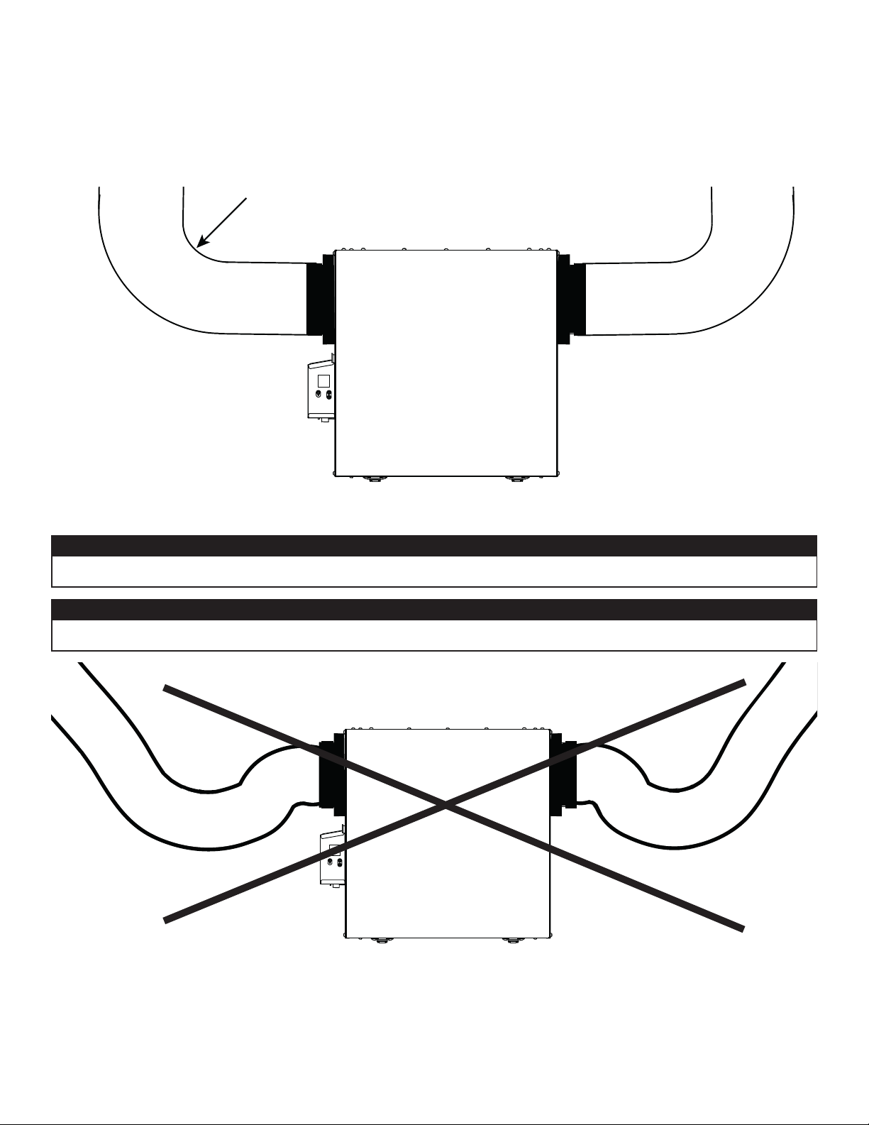
2.6.1 DUCTS CONNECTION
IMPORTANT: Make sure to connect ducting as illustrated below to get airfl ows reading accuracy. Correct installation will
also allow proper drainage of water that may accumulate in ducting.
CORRECT INSTALLATION
R = 3" minimum
VD0489
CAUTION
Ducting must not be too crushed. Otherwise, airfl ows reading accuracy will be affected.
CAUTION
Insulated ducts must have the same diameter as the ports to ensure proper drainage of water that may accumulate in ducts.
INCORRECT INSTALLATION
VD0490
NOTE: Route ducts as straight as possible, minimize the number of elbows and design and install ducts in accordance with
ACCA’s Manual D.
10
Page 11
3. CONNECTIONS
3.1 ELECTRICAL CONNECTION TO OPTIONAL MAIN WALL CONTROL
!
WARNING
Always disconnect the unit before making any connections. Failure to cut power could result in electrical shock or damage
to the wall control or electronic module inside the unit.
CAUTION
Never install more than one optional main wall control per unit. Make sure that the wires do not short-circuit between
themselves or by touching any other components on the wall control. Avoid poor wiring connections. To reduce the risk
of electrical interference (noise), do not run wall control wiring next to control contactors or near light dimming circuits,
electrical motors, dwelling/building power or lighting wiring or power distribution panel.
TERMINAL CONNECTOR
UNIT BOTTOM VIEW
HD0491
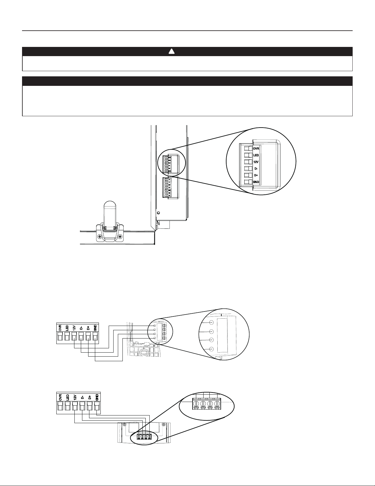
Use the terminal connector included to perform the electrical connection for optional main wall control. Check if all wires are correctly
inserted in their corresponding holes in the terminal connector. Use screws to fi x wires in the terminal connector.
Once the wall control connections have been made, insert the terminal connector in the electrical compartment.
NOTE : For information about the operation of the wall control, refer to the corresponding Installation and User Guide, available at
www.Broan-NuTone.com.
3.1.1 ELECTRICAL CONNECTION TO SPEED, DEHUMIDISTAT OR AUTOMATIC OPTIONAL MAIN WALL CONTROL
12V
D-
D+
Gnd
VC0241
12V
D-
D+
Gnd
3.1.2 ELECTRICAL CONNECTION TO ADVANCED OPTIONAL MAIN WALL CONTROL
12V D- D+ Gnd
VC0242
12V D- D+ Gnd
11
Page 12
3. CONNECTIONS (CONT’D)
3.2 ELECTRICAL CONNECTION TO OPTIONAL AUXILIARY WALL CONTROL
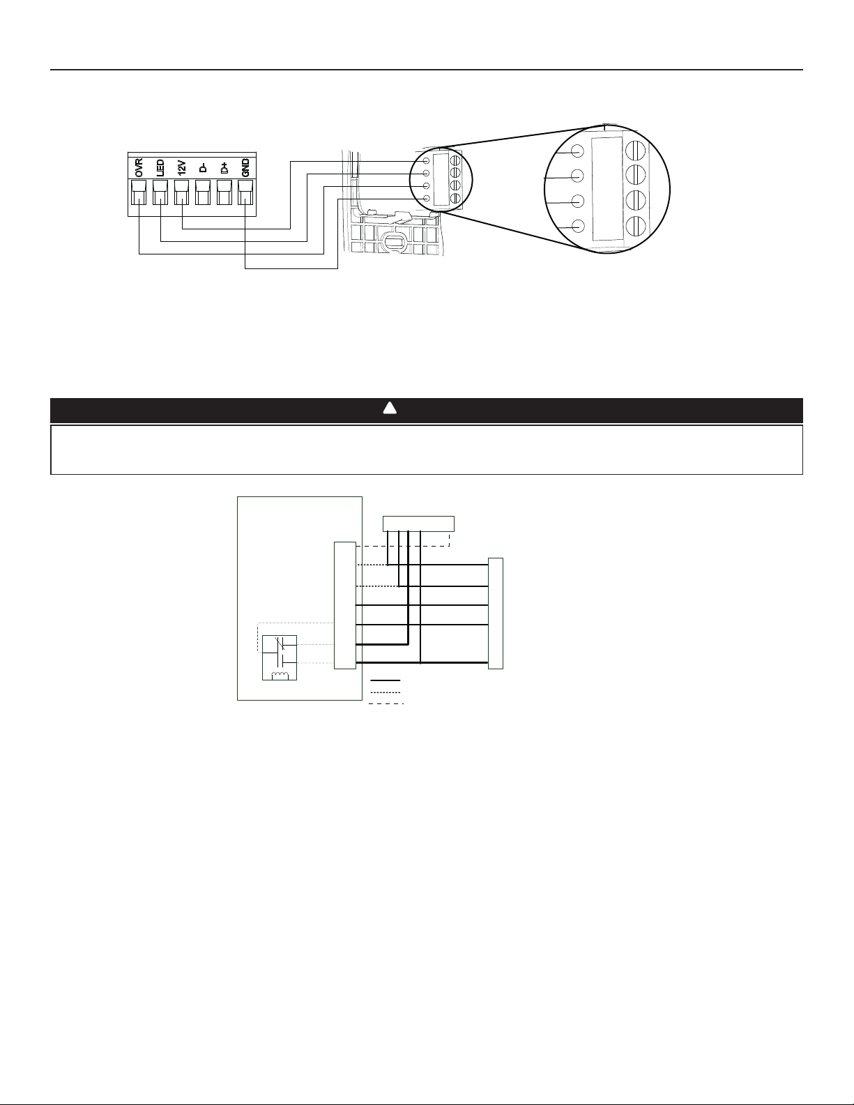
3.2.1 ELECTRICAL CONNECTION TO 20-40-60 OPTIONAL AUXILIARY WALL CONTROL
12V
LED
OVR
Gnd
12V
LED
OVR
Gnd
VC0243
When confi gurating OVR option on the LCD screen, choose among these 3 confi gurations: BAL (the unit remains balanced while
providing maximum airfl ow), PER (the unit is slightly unbalanced since the distribution motor is in MAX speed while allowing maximum
exhaust ventilation) and DIS (the unit is unbalanced since air distribution is constant despite a higher need in exhaust ventilation).
3.3 CONNECTION TO THE CENTRAL FORCED-AIR SYSTEM
!
WARNING
Never connect a 120-volt AC circuit to the terminals of the central forced-air system interlock (standard wiring). Only use
the low voltage class 2 circuit of the central forced-air system blower control. The unit is designed for low voltages only.
Connecting the unit on 120-volt circuit would damage it instantly.
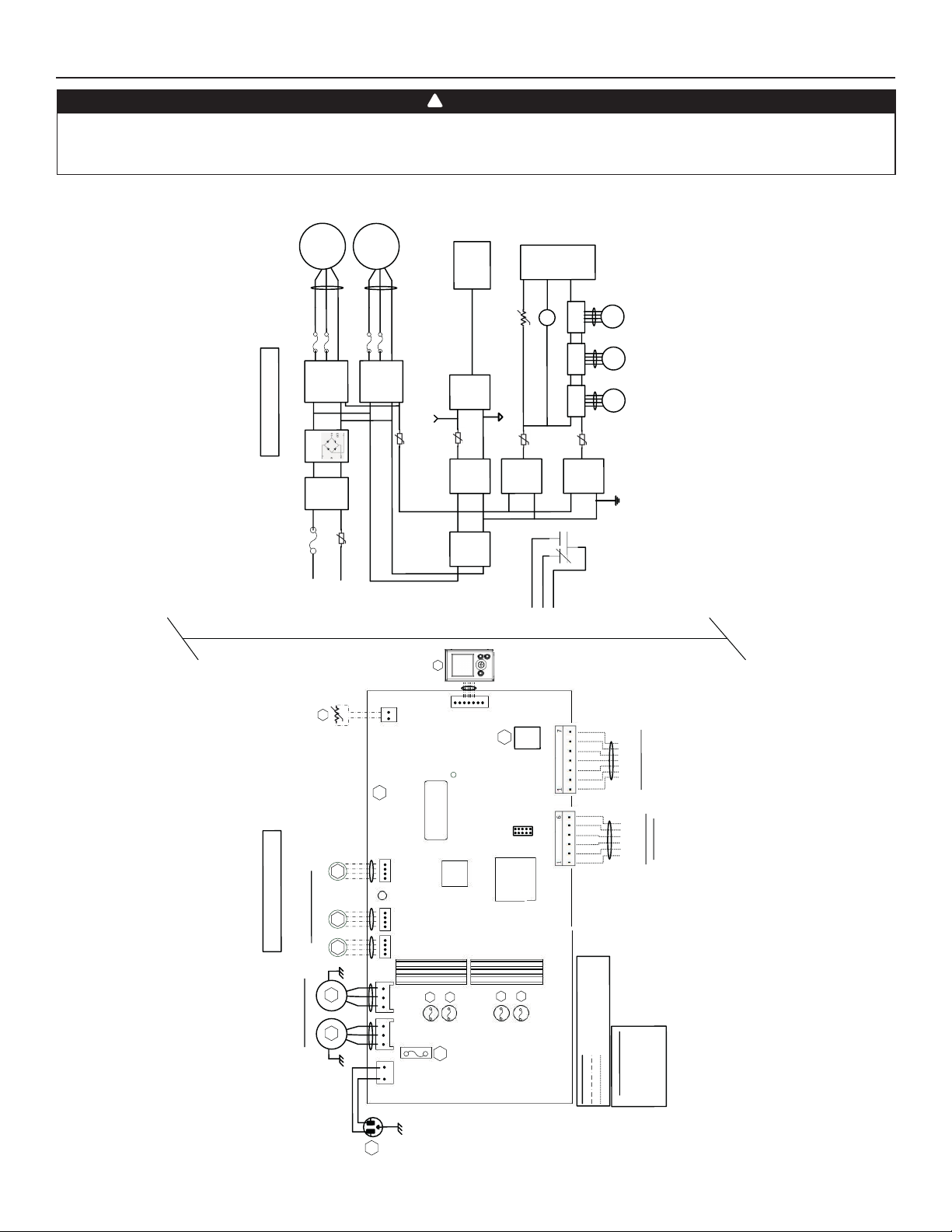
Wiring Options with Central Forced-Air System
VE0451A
Air Exchanger PCB
Terminal Blocks
NC
COM
NO
Internal
Logic
Central Forced-Air System Thermostat
J13
Vent
W
Gf
Y W G R C Acc
Y
C
G
R
Basic Central Forced-Air System / Required Wiring
Optional Wiring for Synchronization
Optional Wiring for Activation from Thermostat
Central Forced-Air System
Y
W
C
G
R
3.3.1 UNIT OPERATION USING A CENTRAL FORCED-AIR SYSTEM THERMOSTAT
If the thermostat is equipped with an optional ventilation output, it is possible to use it to operate the unit. Choose among these 4
confi gurations: minimum (unit operating in MIN speed), intermittent (unit operating in MIN speed 20 min/h then as per INT
confi guration selection for 40 min), auto (unit operating according to outdoor temperature) and maximum (unit operating in MAX
speed) in DRY option on the LCD screen when the VENT contact is activated. Refer to section 5 for more details.
NOTE : This dry contact option will override the main wall control so we do not recommend to use a wall control and the thermostat
together.
3.3.2 UNIT INTERCONNECTION WITH CENTRAL FORCED-AIR SYSTEM (R/C/G/GF)
These connections must be done if you want the unit to force the central forced-air system blower operation when ventilating.
NOTE : These connections are required for installation confi guration T-4. Refer to section 2.2 for more details.
3.3.3 SYNCHRONIZATION WITH CENTRAL FORCED-AIR SYSTEM FUNCTION
The Virtuo technology allows synchronizing the unit operation with the central forced-air system operating time. It prevents unnecessary
central forced-air system operating time while providing a better air distribution.
NOTE : W and Y connections must be added to R and C connections to inform the unit that the central forced-air system is running.
12
Page 13
4. WIRING DIAGRAM
!
WARNING
• Risk of electric shocks. Before performing any maintenance or servicing, always disconnect the unit from its power source.
• This product is equipped with an overload protection (fuse). A blown fuse indicates an overload or a short-circuit situation. If the fuse
blows, unplug the product from the outlet. Discontinue using the unit and contact technical support.
M1
2
To J
3
F
F2
IPM
LOGIC DIAGRAM
Bridge
e
AC
Lin
F1
Line
J1-2
)
(120VAC
High Voltage
r
R1
Thermisto
)
haust
x
otors
(E
er M
)
c
Stepp
tional
ecir
(R
* Op
WIRING DIAGRAM
)
Damper
(Supply
N
s
GR
)
y
n Motor
(Suppl
a
n F
)
ntilatio
(Exhaust
Ve
GRN
M2
LCD
J15a
o
T
ed
Isolat
d
e
solat
I
Assembly
(A2)
)
Supply
(3.3VDC
C3
PT
pply
u
S
(12VDC)
7a
J
To
solated GND
I
3
To J
5
F4
F
IPM
Motor 1
Motor 1
J9
o
T
TC2
P
U
C
M
J5
o
r
T
K1
R1)
(
C4
PT
y
ogic
L
Suppl
eppe
TH1
3.3VDC)
(
M3
Driver
St
6
J
To
river
M4
D
Stepper
J7
o
T
M5
Driver
Stepper
C6
PT
D
ogic
L
Supply
(12VDC)
Digital GN
Filter
1
TC)
RT
(N
eutral
N
J1-1
Y
L
B
D
C
L
SEM
S
A
J7a
NIC
CTRO
E
A1
SSEMBLY
A
MAIN EL
1
M4
M3
M2
M2
M1
J7
s
) i
11
ulation
c
models
l
present for
l
ecir
a
R
Damper (J6
not
J5 J6
B
L
K
3
BLU
RED
B
L
K
B
LU
R
E
D
HT
W
BLK
1
2J
J
1
J1
1
F2
C)
D
wer
Po
Supply
(15V
R
A2
1
15a
J
r
i
A
al
r
em
K1
ent
yst
S
Forced-
C
ower
LED
P
ber
um
N
Serial
MCU
F3
otor Fuses
M
F1
/125VAC
5A
BDM
J1 4
nsformer
a
Isolation
Tr
F5
F4
K1
Gf
G
J13
o
T
ing
r
m Wi
yste
S
ir
Relay
J1 3
1
J9
wiring
age factory wiring
t
voltage factory
ow vol
ine
L
L
)
R
G
4VAC
Gf
tral Forced-A
d 2
C
W
Y
V
(Isolat e
nal Cen
Optio
*
y
liar
D
N
G
uxil
D+
D-
12V
LED
ntrols Wiring
o
R
OV
C
Main and A
g
in
age field wir
t
vol
ODE
ow
L
N
K
C
HITE
W
NGREE
IRING COLOR C
WHT
RED RED
GR
BLU BLUE
BLK BLA
W
GRN
VE0452A
W1
60Hz
120VAC
13
Page 14
5. UNIT AUTO-BALANCING
PREPARATION
Follow these steps to ensure accurate measurements:
• Seal all the ductwork with tape. Close all windows and doors.
• Turn off all exhaust devices such as range hood, dryer and bathroom fans.
• If the installation is in any way connected to a ductwork of a central forced-air system, make sure that the central forced-air system
blower is ON. If not, leave central forced-air system blower OFF.
AUTO-BALANCING PROCEDURE
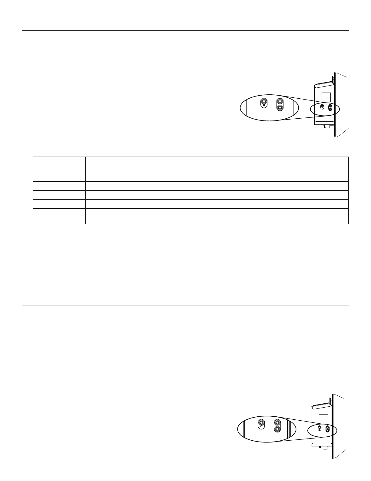
1. Plug the unit and wait for the maximum CFM to display on the LCD screen. At fi rst
boot, it will take longer to get the information since motors have to preheat.
2. The maximum CFM will display on the LCD screen. Use (+/-) to adjust the CFM and
OK to confi rm.
3. The minimum CFM will display on the LCD screen. Use (+/-) to adjust the CFM and
OK to confi rm.
4. INS will display on the LCD screen. Choose among T-1, T-2, T-3, T-4 or T-5 following the
installation confi guration (Refer to section 2.2 for more details).
5. If required, options can be confi gured. While on CFG OPT screen, press on the OK button for 4 seconds. Use (+/-) to change the
confi guration and OK to confi rm. If not required, press OK to skip this menu.
Options Con gurations available
DEF (Defrost) DIS* (Discretion - defrost without speed variation for more comfort),
PLU (Plus - extended defrost for colder areas)
INS (Installation) T-1, T-2, T-3, T-4*, T-5 (Refer to section 2.2)
DRY (Dry contact) MIN* (Minimum), INT (Intermittent), AUT (AUTO), MAX (Maximum) (Refer to section 3.3.1)
OVR (Override) BAL* (Balanced), PER (Performance), DIS (Discretion) (Refer to section 3.2.1)
INT (Intermittent) STB* (Standby - 20 min in MIN speed and 40 min in standby mode), REC** (Recirculation - 20 min in MIN
speed and 40 min in recirculation mode)
* Factory setting
** REC (Recirculation) confi guration is not available for 150H75NT, 150H75NS, 150E75NT and 150E75NS units.
6. Auto-balancing is completed.
NOTE: If no selection is confi rmed within 10 minutes, the unit will exit the menu without saving any changes.
NOTE: If speed or confi guration need to be modifi ed, go to MIN, MAX or CFG using (+/-), then press on the OK button for 4 seconds.
Use (+/-) to increase/decrease speed and OK to confi rm.
If any change is made to the ducting, reset settings to restart the airfl ow test.
VD0492
OK
PROCEDURE TO RESET SETTINGS
Press on the OK and (-) buttons simultaneously for 4 seconds. Use (+/-) to select Yes or No and OK to confi rm.
Then perform the auto-balancing procedure.
+
-
6. USING THIS UNIT
6.1 YOUR VENTILATION SYSTEM
This balanced ventilation unit is designed to provide fresh air to your home while exhausting stale, humid air. Thanks to its energy/heat
recovery module, the unit recovers a large proportion of heat or energy that is part of indoor or outdoor air according to the seasons to
improve comfort and energy effi ciency during the heating and the cooling periods. With the Virtuo Air Technology
to the variations in its environment in an autonomous way, ensuring to provide a proper level of ventilation and air quality. This unit also
features automatic modes (AUTO or SMART) that manage autonomously the required ventilation level as per indoor and/or outdoor
conditions. In colder areas, the unit will perform, at intervals, recovery module discreet defrost to maintain performance and comfort.
TM
, this unit responds
6.2 INTEGRATED CONTROL
All units are equipped with an integrated control, located in front of the electrical compartment. For more convenience, these units can
be controlled using an optional wall control or the central forced-air system thermostat equipped with external fan activation.
MODE SELECTION
1. To change the mode, use (+/-) to access the Mode screen. Press OK to edit the mode
and use (+/-) to change the mode (Standby, Min, Max).
2. Press OK to confi rm selection. The airfl ows will be displayed for both MIN and MAX
modes.
NOTE: If an optional auxiliary wall control or the central forced-air system thermostat
equipped with external fan activation is used, it overrides the integrated control.
OK
VD0492
+
-
14
Page 15
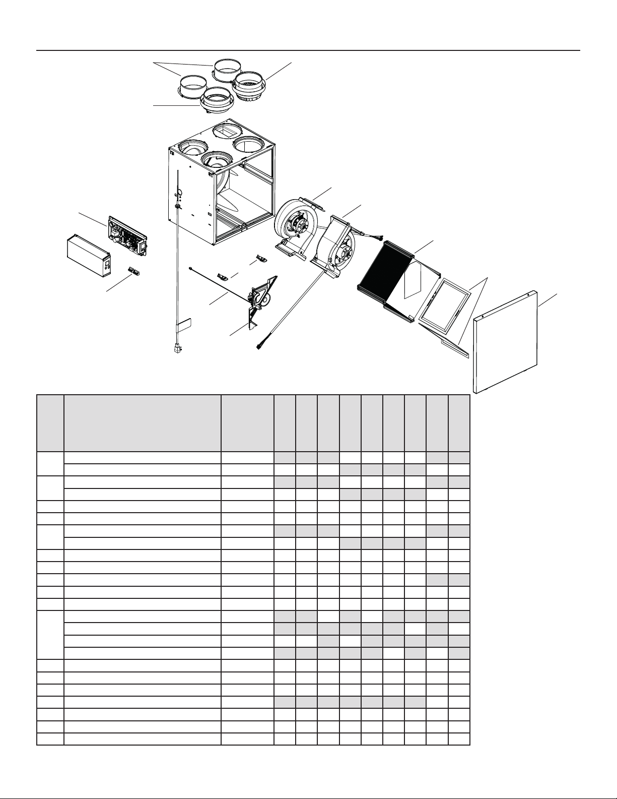
7. SERVICE PARTS
D
E
B
C
H
I
P
G
F
J
O
K
L
M
N
VL0086
ITEM DESCRIPTION PART NUMBER
B110H65RT
B110H65RS
B130H65RT
B130H65RS
B130E65RT
B130E65RS
B160H65RT
B160H65RS
B160E65RT
B160E65RS
6" port warm side SV66139 2222
1
5" port warm side SV66140 2 2 2 2 2
6" metal port motorized damper SV66135 1111
2
5" metal port motorized damper SV66136 1 1 1 1 1
3 Electronic assembly SV66144** 111111111
4 Terminal blocks SV66145 111111111
6" exhaust port assembly SV66137 1111
5
5" exhaust port assembly SV66138 1 1 1 1 1
6 Door latches and keepers for door SV61218 111111111
7 Thermistor SV66134 111111111
8 Recirculation damper with thermistor SV66148 1111111
9 Exhaust blower with damper SV66142 111111111
10 Supply blower assembly SV66141 111111111
Core ERV 65 % SV66113 1 1
Core ERV 75 % SV66114 1 1
11
Core HRV 65 % SV66115 1 1 1
Core HRV 75 % SV66116 1 1
12 MERV8 fi lters kit SV66133 111111111
13 Door SV66150 111111111
14 Exhaust damper SV66143 111111111
15 Separator WE with thermistor SV66149 1 1
* Hardware kit SV66146 111111111
* Fuse for PCB SV66147 111111111
* ½" hose SV00592 111111111
* Not shown.
** See next page to get the part number that corresponds to the ventilation unit model.
B160E75RT
B160E75RS
B160H75RT
B160H75RS
B150H75NT
B150H75NS
B150E75NT
B150E75NS
REPLACEMENT PAR TS AND REPAIRS
In order to ensure your ventilation
unit remains in good working
condition, you must use BroanNuTone LLC genuine replacement
parts only. The Broan-NuTone LLC
genuine replacement parts are
specially designed for each unit
and are manufactured to comply
with all the applicable certifi cation
standards and maintain a high
standard of safety. Any third party
replacement part used may cause
serious damage and drastically
reduce the performance level
of your unit, which will result in
premature failing. Broan-NuTone
LLC recommends to contact a
certifi ed service depot for all
replacement parts and repairs.
15
Page 16
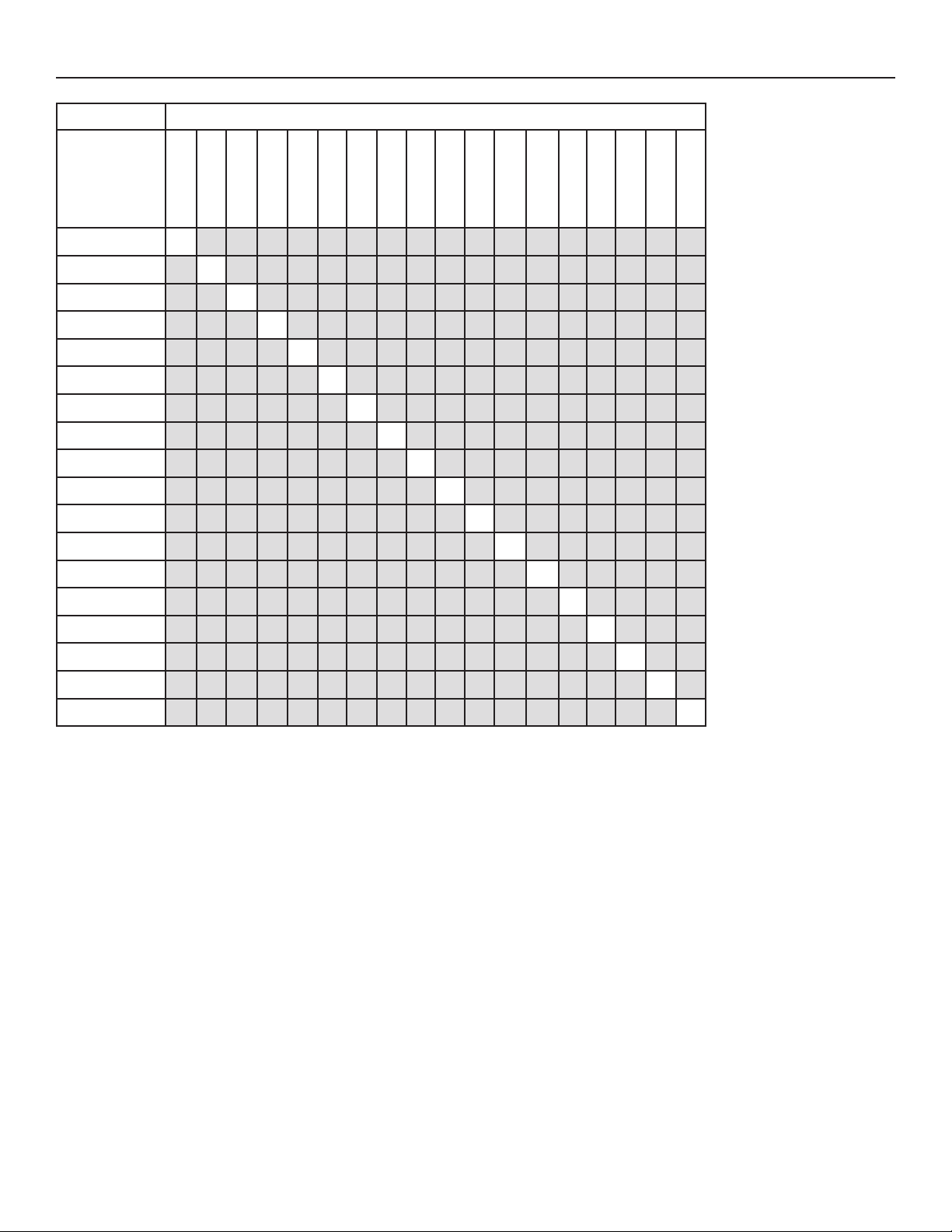
7. SERVICE PARTS (CONT’D)
VENTILATION UNIT MODEL
ELECTRONIC
ASSEMBLY
PAR T NUMBER
B110H65RS
B130H65RS
B110H65RT
B130H65RT
B160H65RT
B160H65RS
B150H75NS
B150H75NT
B160H75RS
SV66144-01 X
SV66144-02 X
SV66144-03 X
SV66144-04 X
SV66144-05 X
SV66144-06 X
SV66144-07 X
SV66144-08 X
SV66144-09 X
SV66144-10 X
B160H75RT
B130E65RS
B130E65RT
B160E65RS
B160E65RT
B150E75NS
B160E75RS
B150E75NT
B160E75RT
SV66144-11 X
SV66144-12 X
SV66144-13 X
SV66144-14 X
SV66144-15 X
SV66144-16 X
SV66144-17 X
SV66144-18 X
16
Page 17
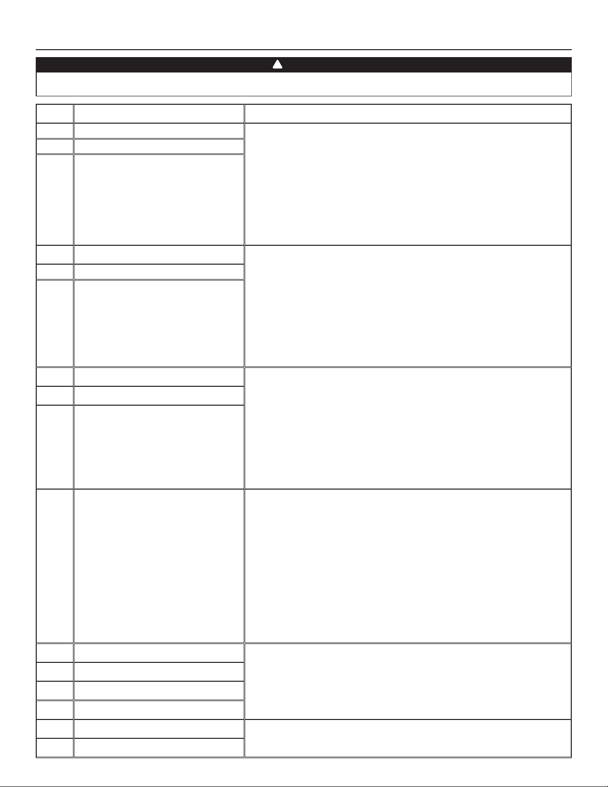
8. INSTALLER’S TROUBLESHOOTING
!
WARNING
The wearing of safety glasses and gloves is recommended since a few diagnosis procedures may require the unit to be in
operation while proceeding. Be careful with moving and live parts to prevent any risk of injury.
ERROR DESCRIPTION SOLUTION
E01 Supply damper range STEP 1: Unplug unit, inspect the damper system, remove any undesirable
E02 Supply damper timeout
E03 Supply damper
E05 Exhaust damper range STEP 1: Unplug unit, inspect the damper system, remove any undesirable
E06 Exhaust damper timeout
E07 Exhaust damper
E09 Recirculation damper range STEP 1: Unplug unit, inspect the damper system, remove any undesirable
E10 Recirculation damper timeout
E11 Recirculation damper
E22 Supply air ow STEP 1: Perform a visual inspection of the supply damper system. Clean fi lters,
E23 Supply motor (drive over current) STEP 1: Unplug/plug unit.
E27 Supply motor (drive foc duration)
E28 Supply motor (drive speed feedback)
E29 Supply motor (startup)
obstacle or dirt (fi lters and core may have to be removed to access the
damper system). Plug unit.
If STEP 1 did not fi x the problem, perform STEP 2: Open electrical
compartment, check if connector J5 (white) is well inserted, check for any loose
wires.
If STEP 2 did not fi x the problem, perform STEP 3: If the damper is not moving
at all, unplug J7 (red) from the electronic assembly, connect the white damper
system connector into J7. If the damper moves (but the system still shows an
error), the electronic assembly must be replaced. Otherwise, replace the damper
system.
obstacle or dirt (fi lters and core may have to be removed to access the
damper system). Plug unit.
If STEP 1 did not fi x the problem, perform STEP 2: Open electrical
compartment, check if connector J7 (red) is well inserted, check for any loose
wires.
If STEP 2 did not fi x the problem, perform STEP 3: If the damper is not moving at
all, unplug J5 (white) from the electronic assembly, connect the white damper
system connector into J5. If the damper moves (but the system still shows an
error), the electronic assembly must be replaced. Otherwise, replace the damper
system.
obstacle or dirt (fi lters and core may have to be removed to access the
damper system). Plug unit.
If STEP 1 did not fi x the problem, perform STEP 2: Open electrical
compartment, check if connector J6 (blue) is well inserted, check for any loose
wires.
If STEP 2 did not fi x the problem, perform STEP 3: If the damper is not moving at
all, unplug J5 (white) from the electronic assembly, connect the blue damper
system connector into J5. If the damper moves (but the system still shows an
error), the electronic assembly must be replaced. Otherwise, replace the damper
system.
distribution registers and outside supply hood. Inspect ducting to ensure it is
not squeezed or bent.
If STEP 1 did not fi x the problem, perform STEP 2: Remove ducting of the supply
path. On the LCD screen, select MAX to check if the unit is able to reach the
selected fl ow. If so, review the ducting path.
If STEP 2 did not fi x the problem, perform STEP 3: On the LCD screen, select the
MIN and MAX fl ow setting values then reset the unit. MAX fl ow value will display
on the LCD screen. If MAX fl ow is above desired MAX fl ow, set MAX and MIN
fl ows.
If STEP 3 did not fi x the problem, perform STEP 4: Replace the supply blower
and repeat STEP 3.
If STEP 4 did not fi x the problem, perform STEP 5: Replace the electronic
assembly.
If STEP 1 did not fi x the problem, perform STEP 2: Remove core and clear the
ventilation wheel from any dirt or obstacles.
If STEP 2 did not fi x the problem, perform STEP 3: Disconnect J2 (white) and
connect a spare blower system. If it works, replace supply blower.
If STEP 3 did not fi x the problem, perform STEP 4: Replace the electronic assembly.
E24 Supply motor (drive over voltage) STEP 1: Unplug/plug unit. Under and over voltage may be detected with severe
E25 Supply motor (drive under voltage)
in-house power supply fl uctuation and stop the motor for protection.
If STEP 1 did not fi x the problem, perform STEP 2: Replace the electronic assembly.
17
Page 18
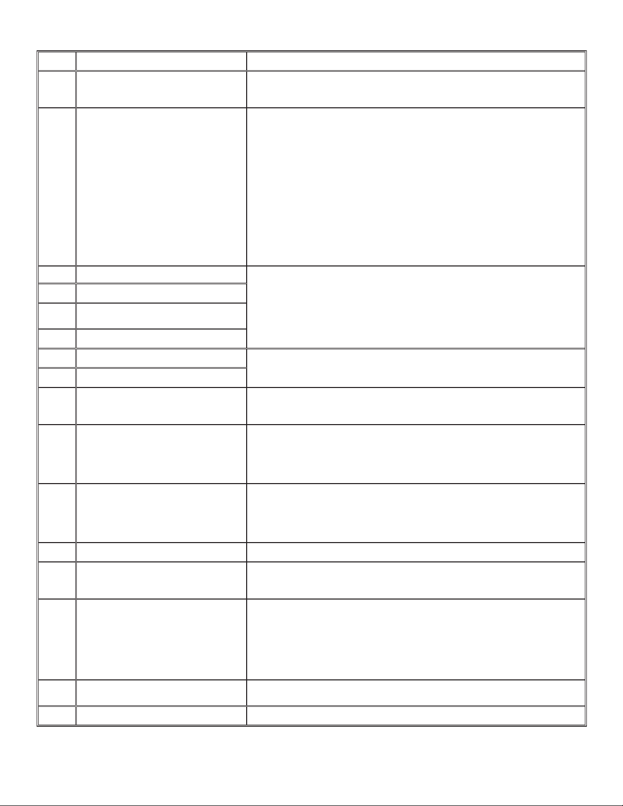
8. INSTALLER’S TROUBLESHOOTING (CONT’D)
ERROR DESCRIPTION SOLUTION
E26 Supply motor (drive over temp) STEP 1: Validate if the air exchanger is exposed to ambient temperatures within
the operating limits (see p. 4)
If STEP 1 did not fi x the problem, perform STEP 2: Replace the electronic assembly.
E32 Exhaust air ow STEP 1: Perform a visual inspection of the exhaust damper system. Clean fi lters,
distribution registers and outside supply hood. Inspect ducting to ensure it is not
squeezed or bent.
If STEP 1 did not fi x the problem, perform STEP 2: Remove ducting of the supply
path. On the LCD screen, select MAX to check if the unit is able to reach the
selected fl ow. If so, review the ducting path.
If STEP 2 did not fi x the problem, perform STEP 3: On the LCD screen, select the
MIN and MAX fl ow setting values then reset the unit. MAX fl ow value will display
on the LCD screen. If MAX fl ow is above desired MAX fl ow, set MAX and MIN
fl ows.
If STEP 3 did not fi x the problem, perform STEP 4: Replace the exhaust blower
and repeat STEP 3.
If STEP 4 did not fi x the problem, perform STEP 5: Replace the electronic
assembly.
E33 Exhaust motor (drive over current) STEP 1: Unplug/plug unit.
E37 Exhaust motor (drive foc duration)
E38 Exhaust motor (drive speed
feedback)
E39 Exhaust motor (startup)
If STEP 1 did not fi x the problem, perform STEP 2: Remove core and clear the
ventilation wheel from any dirt or obstacles.
If STEP 2 did not fi x the problem, perform STEP 3: Disconnect J3 (red) and
connect a spare blower system. If it works, replace exhaust blower.
If STEP 3 did not fi x the problem, perform STEP 4: Replace the electronic assembly.
E34 Exhaust motor (drive over voltage) STEP 1: Unplug/plug unit. Under and over voltage may be detected with severe
E35 Exhaust motor (drive under voltage)
E36 Exhaust motor (drive over temp) STEP 1: Validate if the air exchanger is exposed to ambiant temperatures within
E40 Outside air thermistor STEP 1: Check if thermistor is well connected in connector J7A.
E41 Distribution air thermistor STEP 1: Check if thermistor is well connected in connector J7B.
E42 PCBA thermistor fault STEP 1: Replace the electronic assembly.
E43 PCBA temperature over limit STEP 1: Validate if the air exchanger is exposed to ambiant temperatures within
E50 Wall control communication lost STEP 1: Unplug unit, inspect wires, plug unit.
E51 Wall control sensor STEP 1: Unplug unit, inspect wires, plug unit.
E60 Protection mode STEP 1: Perform general inspection of the unit (dampers, core, fi lters).
in-house power supply fl uctuation and stop the motor for protection.
If STEP 1 did not fi x the problem, perform STEP 2: Replace the electronic assembly.
the operating limits (see p. 4)
If STEP 1 did not fi x the problem, perform STEP 2: Replace the electronic assembly.
If STEP 1 did not fi x the problem, perform STEP 2: Disconnect connector J7A and
check if the measured resistance (thermistor connector) is within 5 Kohms to
120 Kohms. If outside the range, replace the thermistor.
If STEP 2 did not fi x the problem, perform STEP 3: Replace the electronic assembly.
If STEP 1 did not fi x the problem, perform STEP 2: Disconnect connector J7B and
check if the measured resistance (thermistor connector) is within 5 Kohms to
120 Kohms. If outside the range, replace the thermistor.
If STEP 2 did not fi x the problem, perform STEP 3: Replace the electronic assembly.
the operating limits (see p. 4)
If STEP 1 did not fi x the problem, perform STEP 2: Replace the electronic assembly.
If STEP 1 did not fi x the problem, perform STEP 2: Remove wall control from the
wall installation and test with a short cable. If it works, bring a new cable to the
wall installation location.
If STEP 2 did not fi x the problem, perform STEP 3: Test the air exchanger with a
spare wall control. If it works, replace the wall control.
If STEP 3 did not fi x the problem, perform STEP 4: Replace the electronic assembly.
If STEP 1 did not fi x the problem, perform STEP 2: Replace the wall control.
18
Page 19
8. INSTALLER’S TROUBLESHOOTING (CONT’D)
WARNING DESCRIPTION SOLUTION
W22 Supply air ow
W32 Exhaust air ow
W52 Initial setting
incomplete
W61 Protection
mode
electronics
overheating
STEP 1: Perform a visual inspection of the supply damper system. Clean fi lters, distribution
registers and outside supply hood. Inspect ducting to ensure it is not squeezed or bent.
If STEP 1 did not fi x the problem, perform STEP 2: Remove ducting of the supply path. On the
LCD screen, select MAX to check if the unit is able to reach the selected fl ow. If so, review the
ducting path.
If STEP 2 did not fi x the problem, perform STEP 3: On the LCD screen, select the MIN and MAX
fl ow setting values then reset the unit. MAX fl ow value will display on the LCD screen. If MAX fl ow
is above desired MAX fl ow, set MAX and MIN fl ows.
If STEP 3 did not fi x the problem, perform STEP 4: Replace the supply blower and repeat STEP 3.
If STEP 4 did not fi x the problem, perform STEP 5: Replace the electronic assembly.
STEP 1: Perform a visual inspection of the exhaust damper system. Clean fi lters, distribution
registers and outside supply hood. Inspect ducting to ensure it is not squeezed or bent.
If STEP 1 did not fi x the problem, perform STEP 2: Remove ducting of the supply path. On the
LCD screen, select MAX to check if the unit is able to reach the selected fl ow. If so, review the
ducting path.
If STEP 2 did not fi x the problem, perform STEP 3: On the LCD screen, select the MIN and MAX
fl ow setting values then reset the unit. MAX fl ow value will display on the LCD screen. If MAX fl ow
is above desired MAX fl ow, set MAX and MIN fl ows.
If STEP 3 did not fi x the problem, perform STEP 4: Replace the exhaust blower and repeat STEP 3.
If STEP 4 did not fi x the problem, perform STEP 5: Replace the electronic assembly.
STEP 1: Press + or - to access the selection menu.
STEP 2: Complete confi guration. (Refer to section 5 for more details).
The unit is currently in protection mode. The power transmitted to the motor is deliberately
reduced to decrease electronics temperature. The unit will exit this mode by itself once conditions
are back to normal. It is normal to observe reduction in airfl ows during this period. This
condition should appear only when the unit is located in a warm environment, for example over
60°C (140°F). If this condition appears while the unit is located in an environment where the
ambient temperature is under 30°C (86°F), replace the electronic assembly.
19
Page 20
9. MAINTENANCE
V
!
WARNING
High voltage risk. During maintenance or repairs, always stop the unit then unplug it to prevent any risk of electric shock.
The wearing of safety glasses and gloves is recommended when handling unit components to prevent any risk of injury that
could be caused by the presence of thin metal.
9.1 QUARTERLY
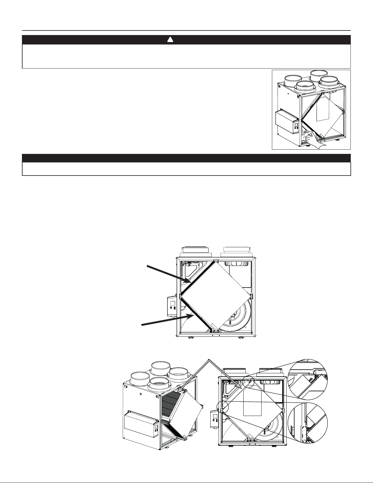
1. Disconnect power cord.
2. The door of this unit is hinged and maintained closed by 2 latches. Open them and set aside.
3. Clean the inside of the door with a damp cloth.
4. Clean fi lters:
• Remove fi lters.
• Vacuum to remove most of the dust.
• Wash with a mixture of warm water and mild soap. You may add bleach if you wish to disinfect (one
tablespoon per gallon). Rinse thoroughly. Shake fi lters to remove excess water and let dry.
Note: The optional MERV13 fi lter is a disposable fi lter. It should be replaced when it is too dirty.
5. Clean the condensing tray with a damp cloth.
6. Check the exterior air intake hood:
CAUTION
A blocked air vent or fi lter, even partially, could cause the unit to malfunction. The comfort provided by the unit could be
reduced and the risk of unit frost could increase. This could cause unit breakdown and/or damage to property.
• Make sure there are no leaves, twigs, ice or snow that could be drawn into the vent.
• Clean if necessary.
7. Reassemble the components. Pay special attention to the fi lters by making sure that they are engaged in their slots.
8. Rotate the blower wheels by hand. If one of the wheels does not rotate easily, contact your installer.
9. Close the unit door and reconnect power supply.
10. Reset fi lters, if required. If using an optional main wall control (S
5 seconds to reset the fi lters
. If using the ADVANCED optional main wall control, follow the instructions on the touch screen.
PEED, DEHUMIDISTAT OR AUTOMATIC), press on the INT/AUTO button for
D0493
MERV8 FILTER INCLUDED
EXHAUST FILTER INCLUDED
Pull the core 3" to 4" out.
Install the MERV13 fi lter over
the core as illustrated hereafter.
Push the core and the MERV13
fi lter to the bottom of the unit.
VD0494
OPTIONAL MERV13 FILTER (EXHAUST FILTER NOT INCLUDED)
NOTE: The optional MERV13 fi lter replaces the MERV8 fi lter.
20
Page 21
9. MAINTENANCE (CONT’D)
9.2 ANNUAL (AT FALL)
1. Repeat steps 1 to 6 from the previous section and continue with the following steps:
CAUTION
• Handle the recovery core with care.
2. Clean the recovery core:
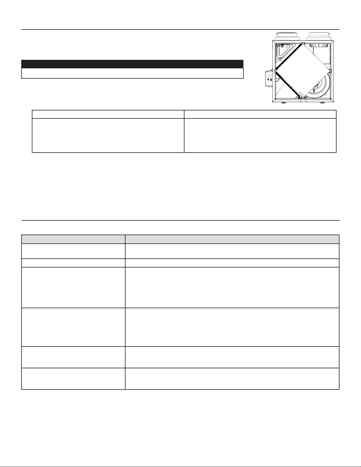
HRV MODELS ERV MODELS
• Remove the core.
• Let it soak in a mixture of cold or lukewarm water and mild
soap (dishwashing liquid).
• Rinse thoroughly.
• Shake the core to remove excess water and let it dry.
3. Clean the blower assemblies. Do not disassemble the blower assemblies.
4. Remove the dust using a vacuum cleaner with a soft brush attachment.
5. Reassemble the components.
6. Reconnect power supply.
Remove the dust on the core using a vacuum cleaner and a
soft brush attachment.
CAUTION: DO NOT SOAK THE ENERGY RECOVERY
VD0494
CORE IN WATER
10. USER’S TROUBLESHOOTING
Contact customer service at 1-800-558-1711 for any unresolved issue.
PROBLEM TRY THIS
1. Nothing works. • See if the unit is plugged in.
• See if the unit is receiving power from the house circuit breaker or fuse.
2. Noisy unit. • Clean the unit (see Section 9). If the problem is not solved, contact your installer.
3. Condensation inside windows under
cold weather conditions.
4. Humidity inside under hot/humid
weather conditions.
5. Air too dry. • Operate the unit at MIN speed.
6. Air too cold at the air supply register. • Make sure the outdoor hoods are not blocked.
• Operate the unit at MAX speed during activities generating excess humidity (family
gatherings, extra cooking, etc.).
• Leave curtains half-open to allow air circulation.
• Store all fi rewood in a closed room with a dehumidifi er or in a well ventilated room, or
store the wood outdoors.
• Keep the temperature in your house above 64°F.
• Operate the unit in MIN speed.
• Temporarily switch to INT mode (if available).
• Use a dehumidifi er.
• Temporarily switch to INT mode (if available).
• Temporarily use a humidifi er.
• Operate the unit at MIN speed.
• Install a duct heater (contact your installer).
21
Page 22

11. WARRANTY
This ventilation unit is a high quality product, built and packaged with care. The manufacturer warrants to the original purchaser of its
product, that such products will be free from defects for the period stated below, from date of original purchase. For all units, the warranty
covers parts only against any operational defect. This 5-year warranty is subject to performance of the core maintenance according
recommendations in this manual. The heat recovery core (HRV) has a limited lifetime warranty, and the energy recovery core (ERV) has
a 5-year warranty. If any defect should occur, we urge you to read the user guide carefully. If the problem persists, observe the following
rules:
RULES TO FOLLOW
If the unit is defective, contact your ventilation contractor (see address on your manual’s cover page). The contractor will determine with
you the reason for the defect, and if needed, do the replacement or repair. If ever it is impossible to reach your ventilation contractor, call
1-800-558-1711 (in North America); the personnel will be pleased to give you the phone number of a distributor or a service center near
you.
REPLACEMENT PARTS AND REPAIR
In order to ensure your ventilation unit remains in good working condition, you must use the Broan genuine replacement parts only. The
Broan genuine replacement parts are specially designed for each unit and are manufactured to comply with all the applicable certifi cation
standards and maintain a high standard of safety. Any third party replacement part used may cause serious damage and drastically reduce
the performance level of your unit, which will result in premature failing. Broan also recommends that you contact a service depot certifi ed
by the manufacturerfor all replacement parts and repair.
BILL OF PURCHASE
No replacement or repair covered by the warranty will be carried out unless the unit is accompanied by a copy of the original bill of
purchase. Please retain your original.
MISCELLANEOUS COSTS
In each case, the labor costs for the removal of a defective part and/or installation of a compliant part will not be covered by the
manufacturer.
CONDITIONS AND LIMITATIONS
These units are created for residential use only and must be used in a building as defi ned below:
Building: All structures zoned and/or erected for the act, process or art of human or animal habitation and/or the storage or
warehousing of goods.
Residential use: Dwelling, lodging, suite: Building, or part of a building, intended to act as either the domicile to one or several people
which can include general sanitary, food consumption and rest facilities. Buildings of only one room or a group of
rooms including those occupied by a tenant or owner; comprise the lodgings, the individual rooms of the motels,
hotels, rooming/lodging houses, boarding/half-way/foster homes, dormitories, and suites, as well as the stores and the
business establishments constituted by only one room in a dwelling.
Commercial use: Agricultural establishment, commercial establishment for assembly, care, or detention: Building or part of a building that
does not contain a dwelling, situated on land dedicated to agriculture or farming and used primarily to shelter animals,
or for the production, the storage or the treatment of agricultural or horticultural products or animal food. Building or
part of a building, used for the display or retail of goods, professional or personal services, or commodities. Building,
or part of a building used by persons gathering for civic activities, religious or political assembly, tourism, educational/
vocational training, recreation or the consumption of food or drink. Building, or part of a building used to shelter
persons of impaired physical or psychological states, persons requiring palliative care or medical treatments, or persons
for reasons out of their control, cannot escape harm or threat of danger autonomously.
Industrial use: Building, or part of a building, used for the assembly, the manufacture, the creation, the treatment, the repair or
the storage of products and combustible materials and that contain fuels that when ignited or exploded in suffi cient
quantity may constitute a risk of fi re.
The above warranty applies to all cases where the damage is not a result of poor installation, improper use, mistreatment or negligence,
acts of God, or any other circumstances beyond the control of the manufacturer. Furthermore, the manufacturer will not be held
responsible for any bodily injury or damage to personal property or real estate, whether caused directly or indirectly by the unit. This
warranty supersedes all prior warranties.
Broan 926 West State Street, Hartford, WI 53027 www.broan.com 800-558-1711
22
Page 23
MANUAL DEL USUARIO Y DEL INSTALADOR
B110H65RT* B110H65RS*
B130H65RT* B130H65RS*
B130E65RT B130E65RS
B150H75NT* B150H75NS*
B160H75RT* B160H75RS*
B160H65RT* B160H65RS*
B160E65RT B160E65RS
VB0288
REGISTRE SU PRODUCTO EN LÍNEA EN:
www.broan-nutone.com/en-us/home/customer-service/product-registration
Para obtener más información, visitar nuestro sitio www.Broan-NuTone.com
INSTALADOR: LEA ESTAS INSTRUCCIONES
GUÁRDELAS PARA EL USUARIO
PARA USO RESIDENCIAL ÚNICAMENTE
*ESTOS PRODUCTOS OBTUVIERON LA DENOMINACIÓN
ENERGY STAR® AL CUMPLIR LAS ESTRICTAS DIRECTRICES
DE EFICIENCIA ENERGÉTICA ESTABLECIDAS POR EL MINISTERIO
DE RECURSOS NATURALES DE CANADÁ Y LA EPA DE
ESTADOS UNIDOS. CUMPLEN CON LOS REQUISITOS DE
ENERGY STAR ÚNICAMENTE CUANDO SE UTILIZAN EN
CANADÁ.
23832 REV. 07
Page 24

Este manual utiliza los siguientes símbolos para hacer hincapié en determinada información:
⚠ ADVERTENCIA
Se refi ere a una instrucción que, si no se sigue, puede provocar lesiones personales graves, incluso causar la muerte.
PRECAUCIÓN
Denota una instrucción que, si no se sigue, puede dañar gravemente el aparato y/o sus componentes.
NOTA: Indica la información complementaria necesaria para completar una instrucción.
LIMITACIÓN
Para instalación residencial (doméstica) solamente. Los trabajos de instalación y el cableado eléctrico han de ser realizados por personas
cualificadas, de conformidad con todos los códigos y normas aplicables, incluyendo los códigos y normas de construcción contra
incendios.
⚠ ADVERTENCIA
PARA REDUCIR EL RIESGO DE FUEGO, CHOQUE ELÉCTRICO O HERIDAS CORPORALES, SIGA LAS INDICACIONES SIGUIENTES:
1. Utilice este aparato sólo en la forma prevista por el fabricante.
2. Antes de realizar tareas de mantenimiento o de limpiar el aparato, desenchufe el cable de alimentación de la toma eléctrica.
3. Este aparato no ha sido pensado para proporcionar aire de combustión o de dilución para aparatos que queman combustible.
4. Al cortar o taladrar en una pared o en el techo, procure no dañar el cableado eléctrico ni otras instalaciones ocultas.
5. No use el aparato con un dispositivo de control de velocidad de semiconductores diferente de los que se indican en la sección 3.1.
6. Este aparato debe conectarse a tierra. El cable de alimentación lleva un enchufe de 3 patillas con toma de tierra para su seguridad
personal. Debe enchufarse en una toma de corriente para tres patillas, conectada a tierra de acuerdo con el código eléctrico
nacional y los códigos y ordenanzas locales. No retire la patilla de la toma de tierra. No utilice el aparato con un cable prolongador.
7. No instale el aparato en un espacio donde se cocina ni lo conecte directamente a otro aparato.
8. No lo use para evacuar materias ni vapores peligrosos o explosivos.
9. Para la instalación, el mantenimiento o la limpieza del aparato se aconseja llevar lentes y guantes de seguridad.
10. Cuando la reglamentación local aplicable sea más restrictiva en materia de instalación o certifi cación, dicha reglamentación prevalecerá
sobre las exigencias de este manual y el instalador acepta atenerse a dicha reglamentación y asumir los gastos correspondientes.
PRECAUCIÓN
1. Para evitar que los fi ltros se obstruyan prematuramente, apague el aparato durante las obras de construcción o renovación.
2. Para mayor información sobre otras exigencias, lea la etiqueta de especifi caciones que viene en el aparato.
3. Asegúrese de sacar el aire al exterior. No introduzca ni evacue el aire en espacios situados entre paredes, en el techo o en un desván,
en sótanos pequeños ni en cocheras. No intente recuperar el aire de salida de una secadora o de una campana.
4. Aparato para instalación residencial únicamente, de acuerdo con las exigencias de la norma 90B de la NFPA (para un aparato
instalado en EE.UU.) o con la parte 9 del Código Nacional de la Construcción de Canadá (para un aparato instalado en Canadá.
5. No pase ningún conducto de aire por encima o a menos de 2 pies (0,61 m) de una caldera o de su cámara de alimentación, de un
calentador o de otro aparato que genere calor. Si hay que conectar un conducto a la cámara de retorno de una caldera, debe situarse
al menos a 10 pies (3,1 m) de la conexión de la cámara con la caldera.
6. La instalación de los conductos debe hacerse de conformidad con todos los códigos locales y nacionales aplicables.
7. Al ausentarse de la vivienda durante un periodo largo (más de dos semanas), una persona responsable debería verifi car regularmente
si el aparato funciona correctamente.
8. Si los conductos pasan a través de un espacio no acondicionado (como un desván), el aparato debe funcionar constantemente,
excepto cuando haya que hacer tareas de mantenimiento o reparaciones. Asimismo, la temperatura ambiente de la casa nunca
debería bajar de 65°F.
9. No use el aparato durante la construcción o renovación de su casa o cuando se lije paredes de yeso. Ciertos tipos de polvo y vapores
pueden dañar su sistema.
10. Las piezas mecánicas y electrónicas del aparato deberían ser examinadas por personal de servicio cualifi cado al menos una vez al año.
11. Asegúrese en todo momento de que la admisión exterior de aire y las bocas de aire viciado estén libres de nieve durante el invierno.
Es importante comprobar que, durante una gran tormenta de nieve, el aparato no introduzca nieve. Si fuera el caso, por favor,
apague el aparato durante unas horas.
12. Dado que el sistema de control electrónico del aparato utiliza un microprocesador, es posible que no funcione correctamente
debido a los ruidos externos o a fallas de alimentación muy cortas. Si esto ocurre, desenchufe el aparato y espere aproximadamente
10 segundos. A continuación, enchufe de nuevo el aparato.
13. No debería hacer uso excesivo de aparatos de fragrancia o de químicos porque pueden dañar el material de los componentes del
aparato.
2
Page 25

ÍNDICE
1. DATOS TÉCNICOS ...................................................................................................................... 4
1.1 DISTRIBUCIÓN DEL AIRE (FUNCIONAMIENTO NORMAL) ............................................................................. 4
2. INSTALACIÓN ............................................................................................................................. 4
2.1 UBICACIÓN Y MONTAJE DEL APARATO ........................................................................................................... 4
2.2 INSTALACIÓN DE LOS CONDUCTOS Y REGISTROS ....................................................................................... 6
2.2.1 SISTEMA TOTALMENTE EQUIPADO CON CONDUCTOS (T-1) ............................................................................................ 6
2.2.2 SISTEMA EQUIPADO CON CONDUCTOS DE AIRE VICIADO (T-2) ....................................................................................... 6
2.2.3 INSTALACIÓN SIMPLIFICADA (T-4) .............................................................................................................................. 7
2.3 CONEXIÓN DEL DESAGÜE (HRV SOLAMENTE) ............................................................................................... 8
2.4 INSTALACIÓN DE LA BOCA EXTERIOR DOBLE CON EL KIT DE CAMBIO DE SECCIÓN
TANDEM® (OPCIONAL)........................................................................................................................................ 9
2.5 INSTALACIÓN DE LAS BOCAS EXTERIORAS .................................................................................................... 9
2.6 CONEXIÓN DE LOS CONDUCTOS AL APARATO ............................................................................................ 9
2.6.1 CONEXIÓN DE LOS CONDUCTOS ............................................................................................................................ 10
3. CONEXIONES ............................................................................................................................ 11
3.1 CONEXIÓN ELÉCTRICA CON EL CONTROL MURAL PRINCIPAL OPCIONAL ........................................... 11
3.1.1 CONEXIÓN ELÉCTRICA CON EL CONTROL MURAL PRINCIPAL OPCIONAL SELECTOR DE VELOCIDAD,
DEHUMIDOSTATO O AUTOMÁTICO .................................................................................................................................... 11
3.1.2 CONEXIÓN ELÉCTRICA CON EL CONTROL MURAL PRINCIPAL OPCIONAL AVANZADO CON PANTALLA TÁCTIL ........................... 11
3.2 CONEXIÓN ELÉCTRICA CON EL CONTROL MURAL AUXILIAR OPCIONAL .............................................. 12
3.2.1 CONEXIÓN ELÉCTRICA CON EL CONTROL MURAL AUXILIAR OPCIONAL 20-40-60 ............................................................ 12
3.3 CONEXIÓN CON EL SISTEMA CENTRAL DE AIRE FORZADO ..................................................................... 12
3.3.1 FUNCIONAMIENTO DEL APARATO USANDO UN SISTEMA CENTRAL DE AIRE FORZADO ........................................................ 12
3.3.2 INTERCONEXIÓN DEL APARATO CON UN SISTEMA CENTRAL DE AIRE FORZADO (R/C/G/GF) ............................................. 12
3.3.3 SINCRONIZACIÓN CON LA FUNCIÓN SISTEMA CENTRAL DE AIRE FORZADO ...................................................................... 12
4. DIAGRAMA DE CABLEADOS ..................................................................................................13
5. AUTO BALANCEO DEL APARATO .........................................................................................14
6. USO DE ESTE APARATO ........................................................................................................... 14
6.1 SU SISTEMA DE VENTILACIÓN ......................................................................................................................... 14
6.2 CONTROL INTEGRADO ..................................................................................................................................... 14
7. PIEZAS DE RECAMBIO .............................................................................................................15
8. SOLUCIÓN DE PROBLEMAS DEL INSTALADOR .................................................................. 17
9. MANTENIMIENTO ...................................................................................................................20
9.1 TRIMESTRAL ......................................................................................................................................................... 20
9.2 ANUAL (EN OTOÑO) .......................................................................................................................................... 21
10. SOLUCIÓN DE PROBLEMAS POR PARTE DEL USUARIO .................................................. 21
11. GARANTÍA ................................................................................................................................22
3
Page 26
Información al usuario
A. Para asegurar un funcionamiento silencioso del HRV/ERV certifi cado ENERGY STAR, cada modelo de aparato debe instalarse
utilizando técnicas de atenuación acústica adecuadas para la instalación.
B. La forma en que se instala su ventilador de recuperación de calor/energía puede hacer una diferencia signifi cativa a la energía
eléctrica consumida. Para minimizar el consumo eléctrico del ventilador de recuperación de calor/energía, se recomienda un sistema
independiente, totalmente equipado con conductos. Si selecciona una instalación simplifi cada para que su caldera/AHU funciona
para ventilar de sala en sala, una caldera de efi ciencia energética con un motor de ventilador de velocidad variable electrónicamente
conmutado reducirá su consumo de energía y su costo operativo.
C. La instalación de un control de usuario con su modelo de aparato mejorará la comodidad y podría reducir signifi cativamente el
consumo energético del modelo de aparato.
1. DATOS TÉCNICOS
1.1 DISTRIBUCIÓN DEL AIRE (FUNCIONAMIENTO NORMAL)
Aire fresco
hacia el
edifi cio
Aire viciado
hacia el
exterior
Aire
viciado del
edifi cio
Aire
fresco del
exterior
Aire fresco
hacia el
edifi cio
Aire viciado
hacia el
exterior
Aire
viciado del
edifi cio
Aire
fresco del
VF0077
exterior
NOTA: Las dimensiones, los gráfi cos de rendimiento, las tablas del ciclo de descongelación y las especifi caciones fi guran en las hojas
de especifi caciones del aparato. Consulte nuestro sitio web en www.Broan-NuTone.com.
2. INSTALACIÓN
⚠ ADVERTENCIA
Se aconseja llevar guantes y gafas de protección durante la instalación, el mantenimiento o la limpieza del aparato para
reducir el riesgo de lesiones causadas por la presencia de metal delgado y/o de piezas móviles en altura.
2.1 UBICACIÓN Y MONTAJE DEL APARATO
Elija una ubicación adecuada para el aparato:
• En una zona de la vivienda donde la temperatura ambiente se mantenga entre 50°F y 140°F;
• Lejos de las zonas de estar (comedor, sala de estar, dormitorio), de ser posible;
• De forma que sea fácil acceder al interior del armario para las tareas de mantenimiento trimestrales y anuales, y al tablero de control
situado en un lado del aparato;
• Cerca de una pared exterior para limitar la longitud del conducto fl exible aislado que sale del aparato o llega a él;
• Sólo para los aparatos HRV: cerca de un desagüe. Si no hay desagüe cerca, utilice un balde para recoger los residuos líquidos;
• Lejos de chimeneas calientes, tableros eléctricos y otros lugares que presenten peligro de fuego;
• A menos de 6 pies de distancia de una fuente de alimentación (toma de corriente estándar).
4
Page 27
2.1 UBICACIÓN Y MONTAJE DEL APARATO (CONT.)
Suspendido en las viguetas:
• Doble ligeramente los soportes del aparato para insertar las cadenas
provistas.
• Cuelgue el aparato en las viguetas utilizando las cadenas. Los
resortes no son necesarios.
• Asegúrese siempre de que el desnivel del aparato no sea superior a
1/4 pulg.
O
Montado en la pared:
• Seleccione la(s) ubicación/ubicaciones apropriada(s) para los
soportes (véase la ilustración a continuación) según la posición de los
montantes.
• Inserte los soportes suministrados debajo del cuadro del aparato
(véase la ilustración a la derecha).
• Use el tornillo n.o 8 x 3/8 pulg. para fi jar el soporte.
• Usando los 4 tornillos suministrados n.o 8 x 1½ pulg., sujete el aparato
en la pared asegurándose de que los 4 tornillos queden sujetos en un
montante.
• Asegúrese siempre de que el desnivel del aparato no sea superior a
1/4 pulg.
INSTALACIÓN CON 2 SOPORTES INSTALACIÓN CON 4 SOPORTES
VD0485
VD0486
VD0487
5
Page 28
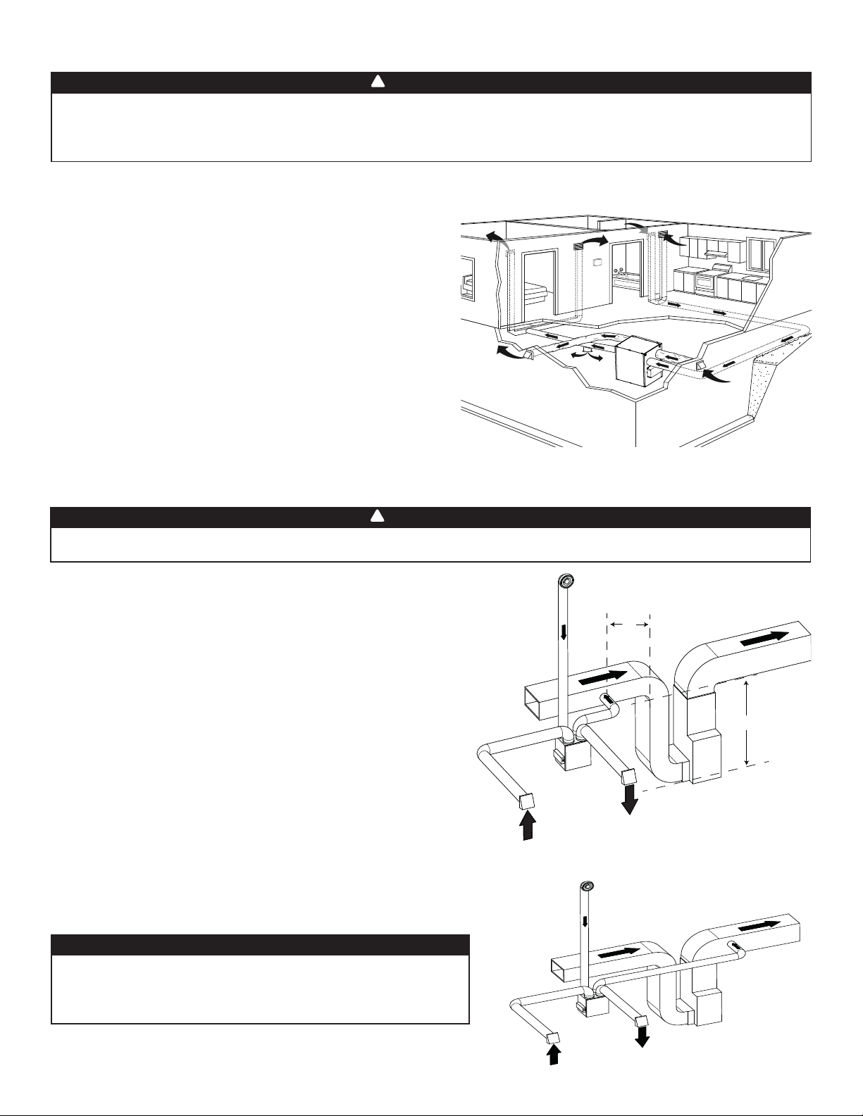
2.2 INSTALACIÓN DE LOS CONDUCTOS Y REGISTROS
!
ADVERTENCIA
No instale nunca un registro de salida de aire viciado en una habitación donde haya un dispositivo de combustión, tal
como una caldera, un calentador de agua a base de gas, una chimenea o cualquier dispositivo o equipo que pueden
producir gases contaminantes o otros tipos de contaminantes. Una presión negativa podría crearse en la habitación y
perjudicar a la evacuación de gases o contaminantes, lo que puede tener consecuencias graves para la salud.
2.2.1 SISTEMA TOTALMENTE EQUIPADO CON CONDUCTOS (T- 1)
CONDUCTOS DE SALIDA DE AIRE VICIADO:
• Instale los registros en zonas donde se produce humedad y
contaminantes: cocina, baño, lavadero, etc.
• Instale los registros sobre una pared interior, a una distancia de 6 a
12 pulgadas del techo O en el techo.
• Instale el registro de la cocina al menos a 4 pies de distancia de la
cocina (aparato).
• Se pueden usar los ventiladores del cuarto de baño y de la campana
de cocina para expulsar mejor el aire viciado.
• Los hogares con más de un nivel necesitan al menos un registro de
salida en el nivel más alto.
CONDUCTOS DE DISTRIBUCIÓN DE AIRE FRESCO:
• Instale registros en dormitorios, comedor, sala de estar y sótano.
• Instale los registros en el techo O en la parte alta de las paredes de
modo que la corriente de aire vaya dirigida hacia el techo.
• Si hay que instalar un registro en el suelo, dirija la corriente de aire
hacia la parte superior de la pared.
NOTA: Para este tipo de con guración, se debe seleccionar la opción T-1 en la pantalla LCD al auto balanceo del aparato.
2.2.2 SISTEMA EQUIPADO CON CONDUCTOS DE AIRE VICIADO (T-2)
!
ADVERTENCIA
La conexión de los conductos al sistema central de aire forzado puede regularse por ciertos códigos y normas. Es su
responsabilidad consultar y aplicar los requisitos locales para evitar incumplimiento.
CONDUCTOS DE SALIDA DE AIRE VICIADO:
Igual que para el sistema totalmente equipado con conductos, descrito
en el punto 2.2.1.
DISTRIBUCIÓN DE AIRE FRESCO:
Conecte el conducto de distribución de aire fresco del aparato con el
conducto de retorno del sistema central de aire forzado por lo menos a 10
pies de distancia del sistema central de aire forzado (A+B)*.
* Esta distancia de 10 pies se aplica solamenta en zonas donde la
temperatura exterior desciende por debajo del punto de congelación
(32°F).
NOTA: El funcionamiento del ventilador impelente del sistema central
de aire forzado puede sincronizarse con el aparato (véase la
sección 3.3). Aunque no es esencial, se aconseja que el ventilador
impelente del sistema central de aire forzado esté funcionando
cuando el aparato esté en marcha.
NOTA: Para este tipo de con guración, se debe seleccionar la
opción T-2 en la pantalla LCD al auto balanceo del aparato.
INSTALACIÓN ALTERNATIVA (T- 3 ):
El aparato debe sincronizarse con el funcionamiento del sistema central
de aire forzado para evitar condensación y crecimiento del moho en los
conductos de distribución del sistema central de aire forzado si el modo
refrigeración del sistema central de aire forzado se utiliza.
VH0165
Aire viciado
del baño
Aire fresco
del exterior
A
Aire fresco hacia
el edi cio
B
Aire viciado
hacia el exterior
A + B = MíN. 10 PIES
Aire viciado
del baño
PRECAUCIÓN
No se recomienda esta confi guración con un sistema central de
aire forzado de alta velocidad. Las presiones elevadas generadas
Aire fresco hacia
el edi cio
por estos sistemas pueden provocar el mal funcionamiento del
aparato y generar errores.
NOTA: Para este tipo de con guración, se debe seleccionar la
opción T-3 en la pantalla LCD al auto balanceo del aparato.
VH0166
Aire fresco
del exterior
Aire viciado
hacia el exterior
6
Page 29
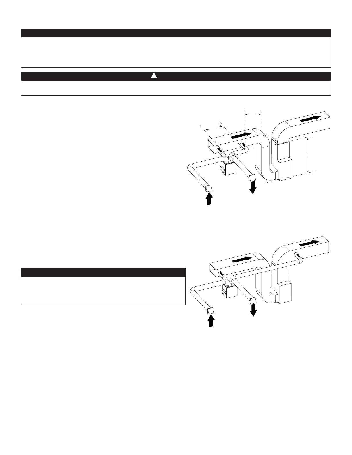
2.2.3 INSTALACIÓN SIMPLIFICADA (T-4 )
PRECAUCIÓN
El sistema central de aire forzado debe estar sincronizado con el aparato porque la evacuación y la distribución de aire
fresco proceden de la misma sección. El sistema central de aire forzado debe funcionar para evitar que el aire fresco sea
directamente aspirado por la evacuación, lo que reduciría considerablemente el aporte de aire fresco al edifi cio. Véase la
sección 3.3 por la conexión.
!
ADVERTENCIA
La conexión de los conductos al sistema central de aire forzado puede regularse por ciertos códigos y normas. Es su
responsabilidad consultar y aplicar los requisitos locales para evitar incumplimiento.
El aire fresco y el aire de salida circulan a través de los conductos del
sistema central de aire forzado, lo que simplifi ca la instalación.
Se sugiere el uso de los ventiladores de los baños y de una campana de
cocina para expulsar el aire viciado.
CONDUCTOS DE SALIDA DE AIRE VICIADO:
Conecte el puerto de admisión de aire viciado del aparato con el
conducto de retorno del sistema central de aire forzado por lo menos 3
pies antes de la distribución de aire fresco del aparato.
DISTRIBUCIÓN DE AIRE FRESCO:
Conecte el conducto de distribución de aire fresco del aparato con el
conducto de retorno del sistema central de aire forzado por lo menos a
10 pies de distancia del sistema central de aire forzado (A+B)*.
* Esta distancia de 10 pies se aplica solamenta en zonas donde la
temperatura exterior desciende por debajo del punto de congelación
(32°F).
NOTA: Para este tipo de con guración, se debe seleccionar la
opción T-4 en la pantalla LCD al auto balanceo del aparato.
Aire viciado
del edi cio
VH0167
C
Aire fresco
del exterior
A
Aire fresco hacia
el edi cio
B
Aire viciado
hacia el exterior
A + B = MíN. 10 PIES
C = 3 PIES
INSTALACIÓN ALTERNATIVA (T- 5 ):
El aparato debe sincronizarse con el funcionamiento del sistema central
de aire forzado para evitar condensación y crecimiento del moho en los
conductos de distribución del sistema central de aire forzado si el modo
refrigeración del sistema central de aire forzado se utiliza.
PRECAUCIÓN
No se recomienda esta confi guración con un sistema central de
aire forzado de alta velocidad. Las presiones elevadas generadas
por estos sistemas pueden provocar el mal funcionamiento del
aparato y generar errores.
NOTA: Para este tipo de con guración, se debe seleccionar la
opción T-5 en la pantalla LCD al auto balanceo del aparato.
Aire fresco hacia
el edi cio
Aire viciado
del edi cio
Aire viciado
hacia el exterior
Aire fresco
del exterior
VH0168
7
Page 30
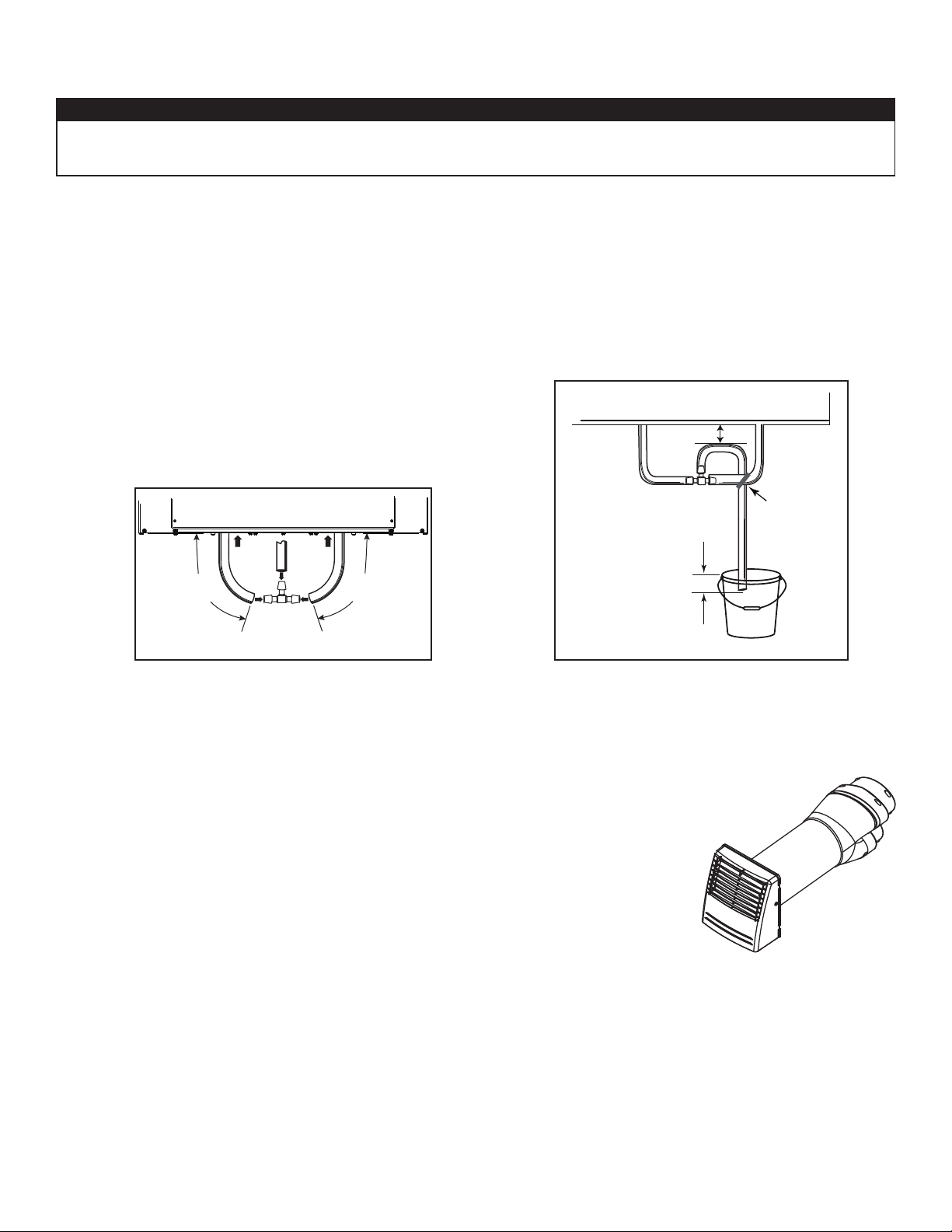
2.3 CONEXIÓN DEL DESAGÜE (HRV SOLAMENTE)
PRECAUCIÓN
Instalar el conducto de desagüe incluido y canalizarlo hacia un dren o un balde. Este aparato puede generar una gran
cantidad de agua cuando hace frío. Es necesario instalar el conducto de desagüe adecuadamente para evitar todo daño
y/o rotura de material.
• Corte la longitud apropriada de conducto de desagüe (véase las ilustraciones a continuación).
• Conecte el conducto al adaptador suministrado.
• Haga un bucle en el conducto de desagüe para evitar que el aparato saque olores desagradables de la fuente de desagüe.
• Agregue agua en el bucle para evitar ruido o silbido.
• Asegúrese de que hay una distancia mínima de 2 pulg. entre el aparato y el bucle en el conducto (véase la ilustración a continuación).
• Use la tira de amarre suministrada para sujetar el conducto tal como ilustrado a continuación.
• Lleve el conducto al desagüe del suelo, a otro conducto de desagüe o a un balde.
• IMPORTANTE: Si utiliza un balde para recoger el agua, sitúe el extremo del conducto a 1 pulg. aproximadamente de la parte
superior del balde para evitar que el agua retroceda al aparato.
≥ 2 pulg.
TIRA DE
AMARRE
13 pulg.
(330 mm)
VO0290E
13 pulg.
(330 mm)
± 1 pulg.
VO0083E
2.4 INSTALACIÓN DE LA BOCA EXTERIOR DOBLE CON EL KIT DE CAMBIO DE SECCIÓN TANDEM® (OPCIONAL)
Para los aparatos confi gurados a 110 pi3/min o menos, si lo desea, puede usar un kit de cambio de
sección Tandem en lugar de 2 bocas exteriores; pero tenga en cuenta que este dispositivo generará
una presión estática adicional de 0,2 pulg. de agua, según la instalación.
El espacio mínimo entre viguetas para instalar el cambio de sección Tandem es de 9 ¾ pulg. La altura
máxima del cambio de sección Tandem es de 8 ¾ pulg.
Para conectar los conductos fl exibles aislados al cambio de sección Tandem (aire viciado hacia el
exterior y aire fresco desde el exterior), siga las instrucciones que vienen con el kit de cambio de
sección Tandem (n.° de pieza VTYIK1).
VR0003
8
Page 31
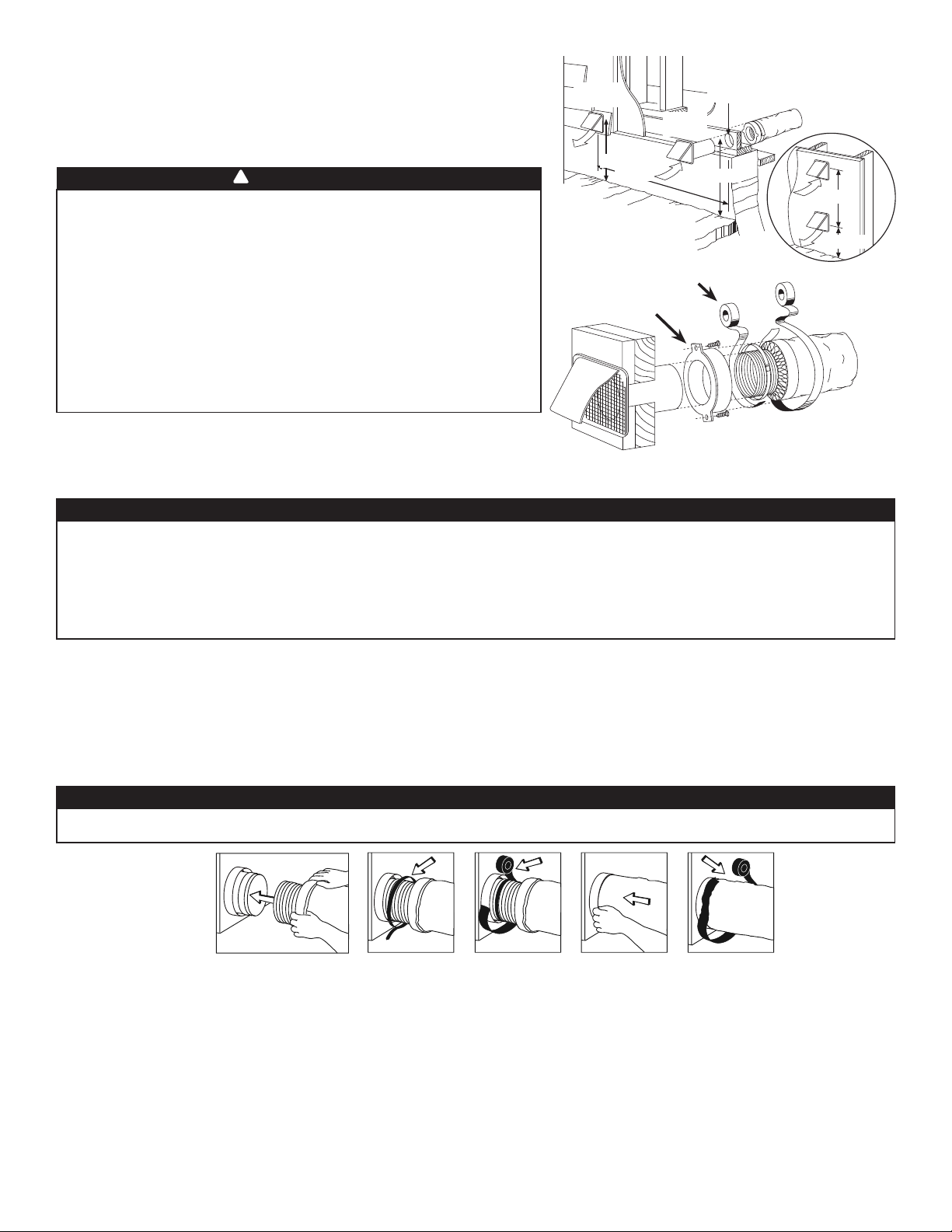
2.5 INSTALACIÓN DE LAS BOCAS EXTERIORAS
Elija un lugar adecuado para las bocas exteriores:
• Debe haber al menos 6 pies entre ambas bocas para evitar la contaminación
cruzada.
• Debe haber una distancia mínima de 18 pulg. hasta el suelo.
!
ADVERTENCIA
Compruebe que la boca de entrada de aire esté al menos a 6 pies
(1,8 m) de distancia de cualquiera de los siguientes elementos:
• Salida de secadora, de sistema central de aire forzado de alta
efi ciencia, de aspiradora central;
• Salida de contador de gas, barbacoa de gas;
• Cualquier salida de una fuente de combustión;
• Cubo de basura y cualquier otra fuente de contaminación.
Ignorar estas recomendaciones podría considerablemente
deteriorar la calidad del aire que entra en la casa, lo que, en
ciertos casos, podría tener repercusiones para la salud.
En caso de confl icto entre nuestras condiciones y los requisitos
locales, prevalecerán estos últimos.
Consulte la ilustración de la derecha para el método de conexión correcto de
los conductos aislados que van a las bocas. En las regiones donde se espera
que caiga mucha nieve debe instalarse una boca de entrada antirráfagas.
2.6 CONEXIÓN DE LOS CONDUCTOS AL APARATO
PRECAUCIÓN
VD0028
BOCA DE
SALIDA
18 PULG.
6 PIES
CINTA Y AMARRE
DEL
MASILLA
BOCA DE
ADMISIÓN
CONDUCTO
6 PULG. ø
18 PULG.
U
BICACIÓN
OPCIONAL DEL
CONDUCTO
6 PIES
18 PULG.
• Si los conductos han de pasar a través de un espacio no acondicionado (p. ej., un desván), use siempre conductos aislados
para evitar la formación de condensación fuera o dentro del conducto, lo que podría provocar roturas de material y/o la
aparición de moho.
• Nunca use tornillos para conectar conductos a los puertos con el fi n de no perturbar el funcionamiento de las
compuertas situadas dentro de los puertos. Una compuerta que no funciona podría congelar el aparato, lo que
podría provocar roturas.
CONDUCTOS FLEXIBLES AISLADOS
Siga el método siguiente para conectar los conductos fl exibles aislados a los puertos del aparato (de aire viciado hacia el exterior y de
aire fresco desde el exterior).
1. Deje a la vista el conducto fl exible, tirando hacia atrás el aislamiento y colóquelo sobre el anillo del puerto interior.
2. Sujete el conducto fl exible al puerto mediante una tira de amarre.
3. Selle la junta con cinta adhesiva para conductos.
4. Tire del aislamiento y de la película impermeable al vapor sobre la junta, métalos entre el anillo interior y el exterior del cuello doble
y sujételos con cinta adhesiva para conductos.
PRECAUCIÓN
La barrera de vapor debe permanecer intacta, sin aberturas o huecos. Una abertura podría generar condensación fuera o
dentro del conducto, lo que podría provocar roturas de material y/o la aparición de moho a largo plazo.
CAMBIO DE SECCIÓN A CONDUCTOS DE 6 PULG. (SOLO PARA APARATOS DE 110, 130 O150 PI3/MIN)
Si utiliza conductos de 6 pulg., instale cambios de sección de 5 a 6 pulg. en los puertos, y sujételos con cinta adhesiva para conductos
solamente. Si utiliza conductos rígidos, instale una sección de conducto fl exible de 12 pulg. entre el cambio de sección y el conducto
rígido (véase más arriba).
ONDUCTOS RÍGIDOS
C
Para evitar posibles fugas de agua en el aislamiento del conducto rígido del lado frío, selle todas las juntas de los conductos rígidos con
cinta adhesiva para conductos. Para evitar la transmisión de vibraciones, use siempre una sección de conducto fl exible de 12 pulg. para
conectar los conductos rígidos al aparato. Para conectar los conductos rígidos aislados al aparato (lado frío) mediante conductos fl exibles
aislados, siga las instrucciones de la sección 2.5. Para conectar los conductos rígidos regulares (lado caliente) al aparato mediante
conductos fl exibles no aislados, utilice una tira de amarre.
NOTA: Se recomienda utilizar conductos de 6 pulg. en lugar de 5 pulg. para los aparatos 150H75NT, 150H75NS, 150E75NT y
150E75NS si el ujo de aire necesario supera 130 pi3/min. Impedirá tener una presión estática demasiado alta en los conductos.
9
Page 32
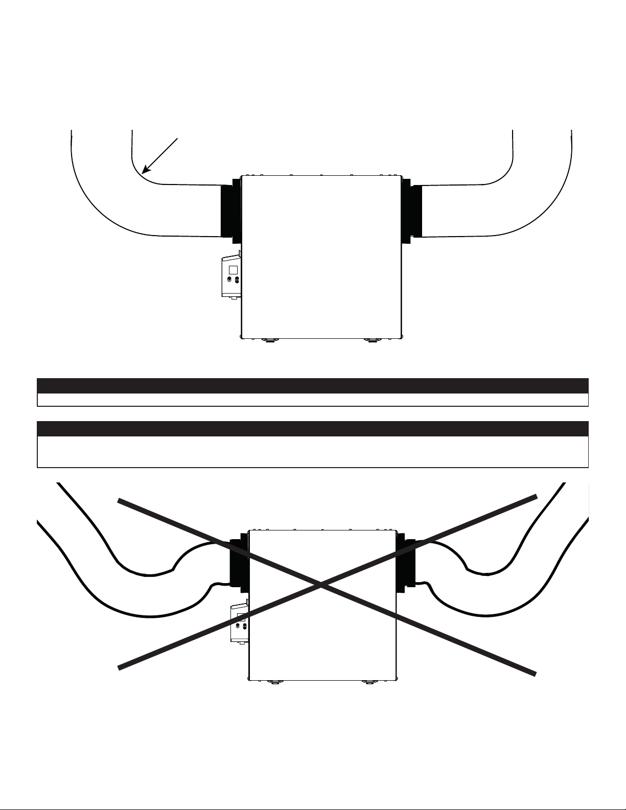
2.6.1 CONEXIÓN DE LOS CONDUCTOS
IMPORTANTE: Asegúrese de conectar los conductos como se ilustra a continuación para obtener una lectura precisa de
los fl ujos de aire. Una instalación correcta también permitirá un drenaje adecuado del agua que se pueda acumular en los
conductos.
INSTALACIÓN CORRECTA
R = 3 pulg. mínimo
VD0489
PRECAUCIÓN
Los conductos no deben estar demasiado aplastados. De lo contrario, la precisión de los fl ujos de aire será afectada.
PRECAUCIÓN
Los conductos aislados deben tener el mismo diámetro que los puertos para asegurar un drenaje adecuado del agua
que se pueda acumular en los conductos.
INSTALACIÓN INCORRECTA
VD0490
NOTA: Instalar los conductos lo más recto posible, reducir el número de codos y diseños y instalar los conductos conforme al
Manual D de ACCA.
10
Page 33
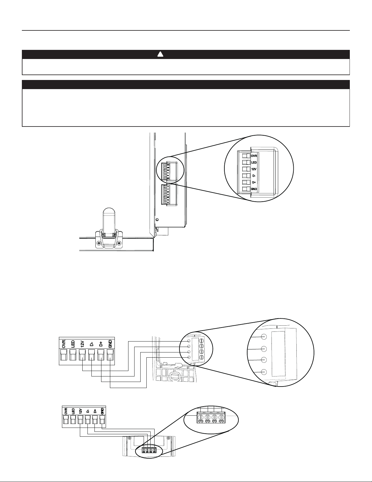
3. CONEXIONES
3.1 CONEXIÓN ELÉCTRICA CON EL CONTROL MURAL PRINCIPAL OPCIONAL
!
ADVERTENCIA
Desconecte siempre el aparato antes de efectuar cualquier conexión. De no cortar la alimentación, podría producirse un
choque eléctrico o dañarse el control mural o el módulo electrónico dentro del aparato.
PRECAUCIÓN
No instale nunca más de un control mural principal opcional por aparato. Compruebe que los cables no se cortocircuiten
entre ellos o tocando otros componentes del control mural. Evite las malas conexiones del cableado. Para reducir el riesgo
de interferencia eléctrica (ruido), no pase los cables del control mural cerca de los contactores de control ni de circuitos
de atenuación de la luz, motores eléctricos, alimentación de viviendas o edifi cios, cables de iluminación o tableros de
distribución de energía.
CONECTOR DE TERMINALES
VISTA INFERIOR DEL
APARATO
Use el conector de terminales incluido para realizar la conexión eléctrica de los controles murales principal y opcional. Verifi que si todos
HD0491
los hilos han sido introducidos en los orifi cios correspondientes en el bloque de terminales. Use tornillos para sujetar los hilos en el
conector de terminales.Una vez conectado el control o controles murales, introduzca el conector de terminales en el compartimento
eléctrico.
NOTA: Para obtener información sobre el funcionamiento del control mural, consulte el Guía de instalación y del usuario, disponible en
www.Broan-NuTone.com
3.1.1 CONEXIÓN ELÉCTRICA CON EL CONTROL MURAL PRINCIPAL OPCIONAL SELECTOR DE VELOCIDAD, DEHUMIDOSTATO O AUTOMÁTICO
12V
D-
D+
Gnd
12V
D-
D+
Gnd
3.1.2 CONEXIÓN ELÉCTRICA CON EL CONTROL MURAL PRINCIPAL OPCIONAL AVANZADO
12V D- D+ Gnd
VC0242
12V D- D+ Gnd
11
Page 34
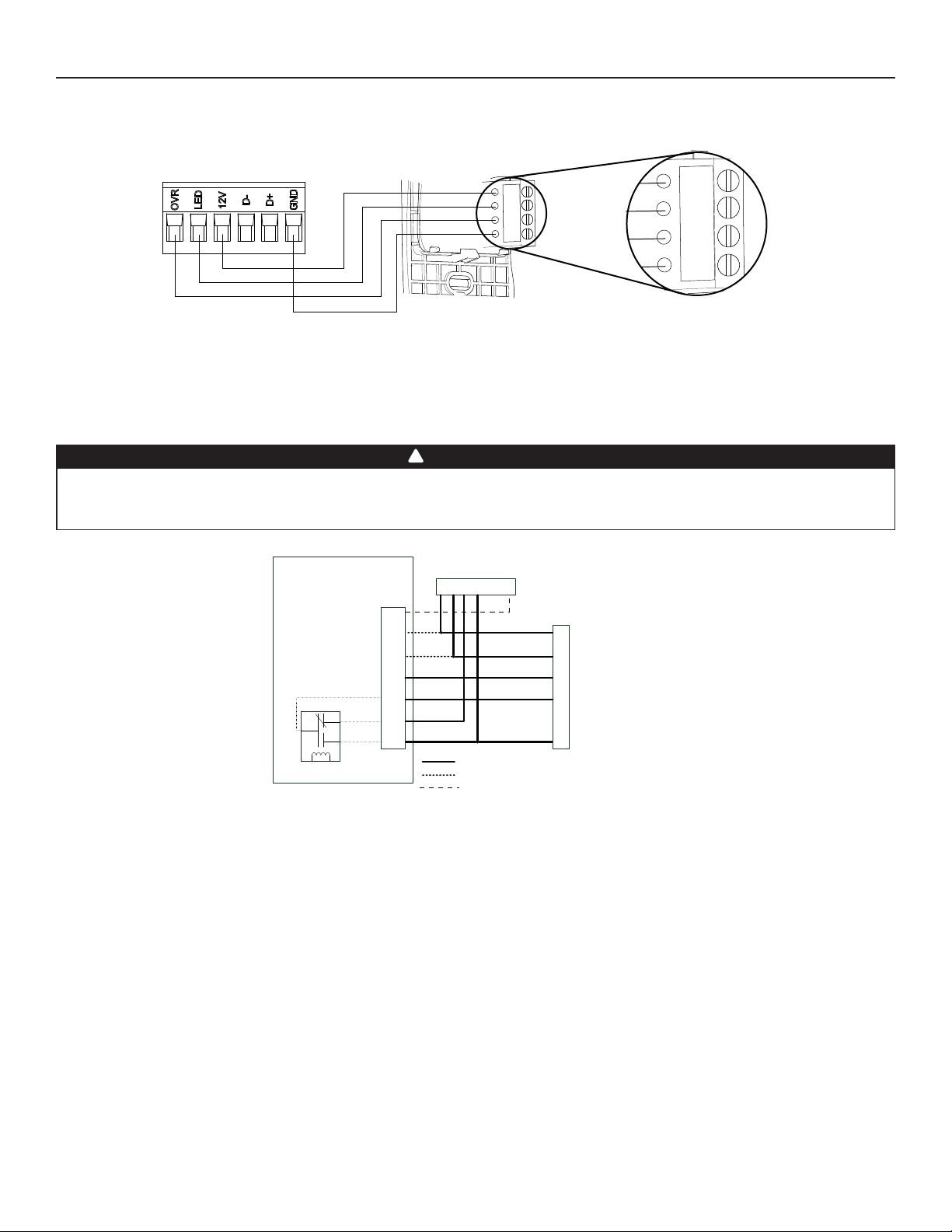
3. CONEXIONES (CONT.)
3.2 CONEXIÓN ELÉCTRICA CON EL CONTROL MURAL AUXILIAR OPCIONAL
3.2.1 CONEXIÓN ELÉCTRICA CON EL CONTROL MURAL AUXILIAR OPCIONAL 20-40-60
12V
LED
OVR
Gnd
12V
LED
OVR
Gnd
Para confi gurar la opción OVR en la pantalla LCD, elija entre estas 3 confi guraciones: BAL (el aparato permanece balanceado al mismo
VC0243
tiempo ofrece fl ujo de aire máximo), PER (el aparato está ligeramente desbalanceado ya que el motor de distribución está en
velocidad MAX al mismo tiempo permite ventilación máxima a la salida) y DIS (el aparato está desbalanceado ya que la distribución de
aire está constante a pesar de una mayor exigencia en ventilación a la salida).
3.3 CONEXIÓN CON EL SISTEMA CENTRAL DE AIRE FORZADO
!
ADVERTENCIA
No conecte nunca un circuito de 120 voltios de corriente alterna a los terminales del interbloqueo del sistema central de aire forzado
(cableado estándar). Utilice sólo el circuito de clase 2 de bajo voltaje del control del ventilador impelente del sistema central de
aire forzado. El aparato está diseñado sólo para baja tensión. Enchufarlo a una tensión de 120 voltios lo dañaría inmediatamente.
Opciones de cableado con sistema central de aire forzado
Bloque de terminales
de la tarjeta electrónica
del intercambiador de aire
COM
VE0451E
Lógica
interna
NC
NO
Termostato del sistema central de aire forzado
J13
Vent
Y
W
C
Gf
G
R
Y W G R C Acc
Sistema central de aire forzado
Sistema central de aire forzado básico /Cableado necesario
Cableado opcional por sincronización
Cableado opcional por activación del termostato
Y
W
C
G
R
3.3.1 FUNCIONAMIENTO DEL APARATO USANDO UN TERMOSTATO DEL SISTEMA CENTRAL DE AIRE FORZADO
Si el termostato está equipado con una salida de ventilación opcional, es posible utilizarla para hacer funcionar el aparato. Elija entre
estas 4 confi guraciones: mínimo (el aparato funciona en velocidad MIN), intermitente (el aparato funciona en velocidad MIN durante
20 min/hora y después conforme a la confi guración de la opción INT durante 40 min), auto (el aparato funciona según la temperatura
exterior) y máximo (el aparato funciona en velocidad MAX) de la opción DRY en la pantalla LCD cuando el contacto VENT está
activado. Consulte la sección 5 para más detalles.
NOTA : Esta opción de contacto seco prevalecerá sobre el control mural principal. No recomendamos el uso conjunto de un control
mural y del termostato.
3.3.2 INTERCONEXIÓN DEL APARATO CON UN SISTEMA CENTRAL DE AIRE FORZADO (R/C/G/GF)
Estas conexiones deben hacerse si quiere que el aparato imponga el funcionamiento del ventilador del sistema central de aire forzado
cuando ventile.
NOTA : Estas conexiones se requieren para la confi guración de instalación T-4. Consulte la sección 2.2 para más detalles.
3.3.3 SINCRONIZACIÓN CON LA FUNCIÓN SISTEMA CENTRAL DE AIRE FORZADO
Virtuo Air technologyTM permite sincronizar el funcionamiento del aparato con el tiempo de funcionamiento del sistema central de
aire forzado. Evita innecesario tiempo de funcionamiento del sistema central de aire forzado además de proporcionar una mejor
distribución del aire.
NOTA : Conexiones W e Y deben añadirse a las conexiones R e C para comunicar al aparato que el sistema central de aire forzado está
en marcha.
12
Page 35
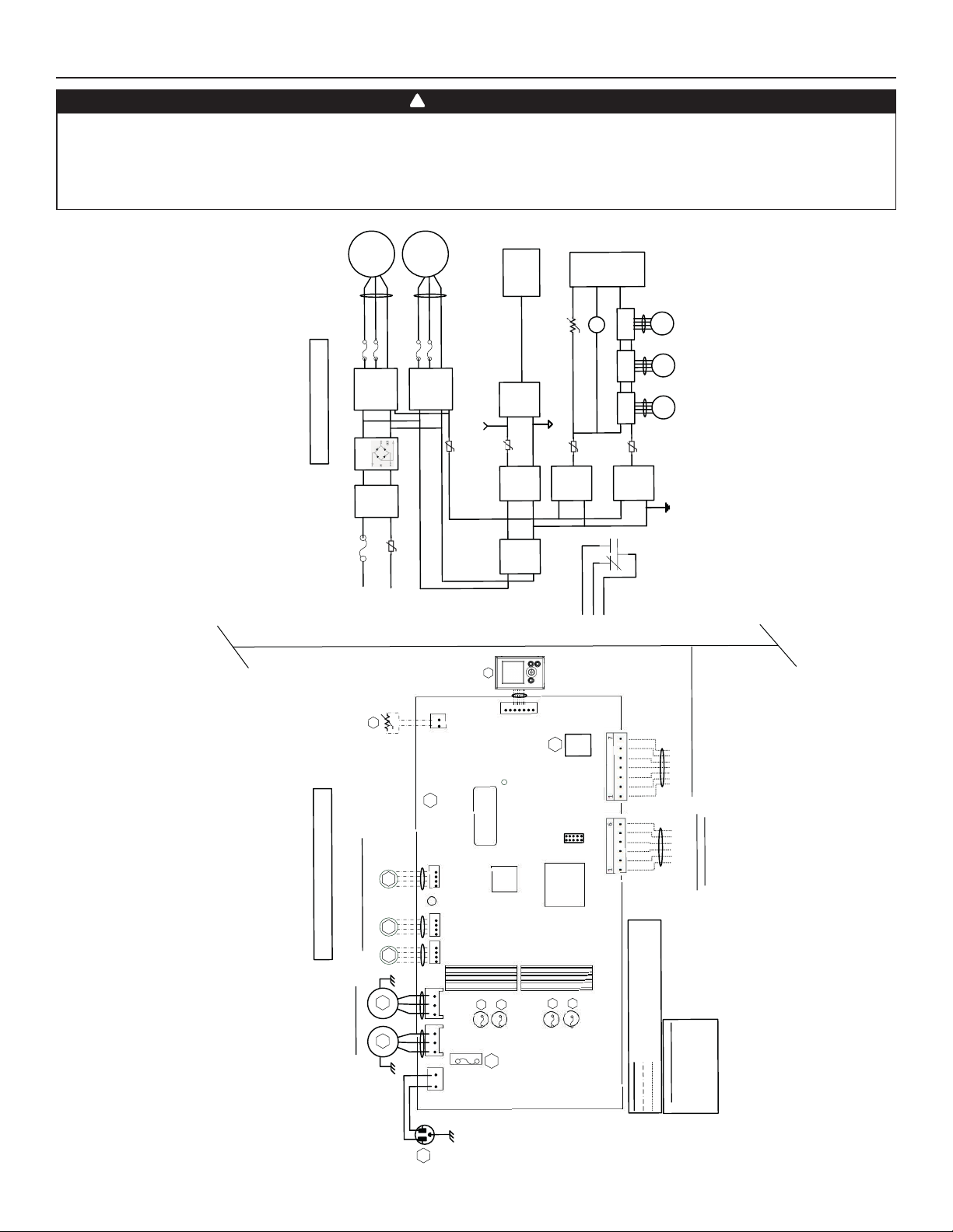
4. DIAGRAMA DE CABLEADOS
!
ADVERTENCIA
• Riesgo de descarga eléctrica. Antes de cualquier trabajo de reparación o mantenimiento, desconecte siempre
el aparato de su fuente de alimentación.
• Este producto está equipado con una protección contra la sobrecarga (fusible). Un fusible fundido indica que se ha
producido una sobrecarga o cortocircuito. Si el fusible se funde, desenchufe el aparato. Deje de utilizar el aparato y
póngase en contacto con el servicio de asistencia técnica.
VE0452
otor 1
M
Filtro
Neutro
J1-1
)
120VCA
(
M4
M3
2
M
M2
M1
M2
LCD
3
To J
5
F4
F
1
IPM
otor
M
2
C
T
P
)
1
T
NTC
R
(
Conjunto
a
J15
A2)
7a
(
o
T
9
J
o
T
n-
lime
A
To J
)
-
i
VDC
nvert
3
rra aislada
o
dor aislado
C
(3.
Tie
3
TC
P
)
-
i
nvert
2VDC
o
(1
dor aislado
C
)
n
DC
ó
V
15
taci
(
U
C
M
5
J
o
T
K1
TH1
(R1)
M3
pasos
Motor de
6
J
To
M4
pasos
Motor de
7
To J
M5
pasos
Motor de
4
C
PT
)
C
ica
VD
lóg
3.3
Función
(
6
C
PT
al
)
ica
lóg
2VDC
Función
Masa digit
(1
K1
R
Gf
G
To J13
orzado
rica de baja tensión
áb
Cableado de f
Cableado in situ de baja tensión
R
G
Gf
C
W
Y
V
D
N
G
D+
-
D
V
2
1
LED
VR
O
IGO DE COLORES
D
CÓ
f
e
r
de ai
central
a
em
onal sist
i
opc
* Cableado
es
ol
r
cont
los
eado de
l
ab
C
CO
AN
BL
Z AZUL
B
A
)
24VCA aislado
(
es
r
incipales y auxilia
pr
ROJO
E NEGRO
R
N
VERDE
V
D
A2
LC
CONJUNTO
zado
15a
J
J7a
1
r
é
ema central
t
el
s
R
de aire fo
si
K1
NICO
Ó
A1
PRINCIPAL
CONJUNTO ELECTR
1
J7
no está
)
1
J6
(
para todos
te
n
os modelos
l
La compuerta de
se
1
pre
5J6
J
recirculación
NE
AZ
R
1
NE
AZ
J2 J3
R
1
J1
B
1
NE
mero de serie
Nú
F2
1
F
D
LE
Luz
CU
M
4
F3
AC
V
5A/125
F
Fusibles del motor
J1 3
BD
M
1
J1 4
J9
ador
m
sfor
ran
T
de aislamiento
5
F
rica de tensión de línea
ableado de fáb
C
M1
2
To J
F3
F2
IPM
DIAGRAMA LÓGICO
Puente
Línea
de CA
F1
Línea
J1-2
Alta tensión
or
t
s
1
R
Termi
)
(Extracción
)
cional
s de pasos de la compuerta
(Recir c
)
ore
* Op
t
DIAGRAMA DE CABLEADOS
Mo
(Alimentación
)
Tierra
ción
a
nt
Alime
(
)
(Extracción
Motores del ventilador
Tierra
Tierra
z
W1
60H
E
120VCa
13
Page 36
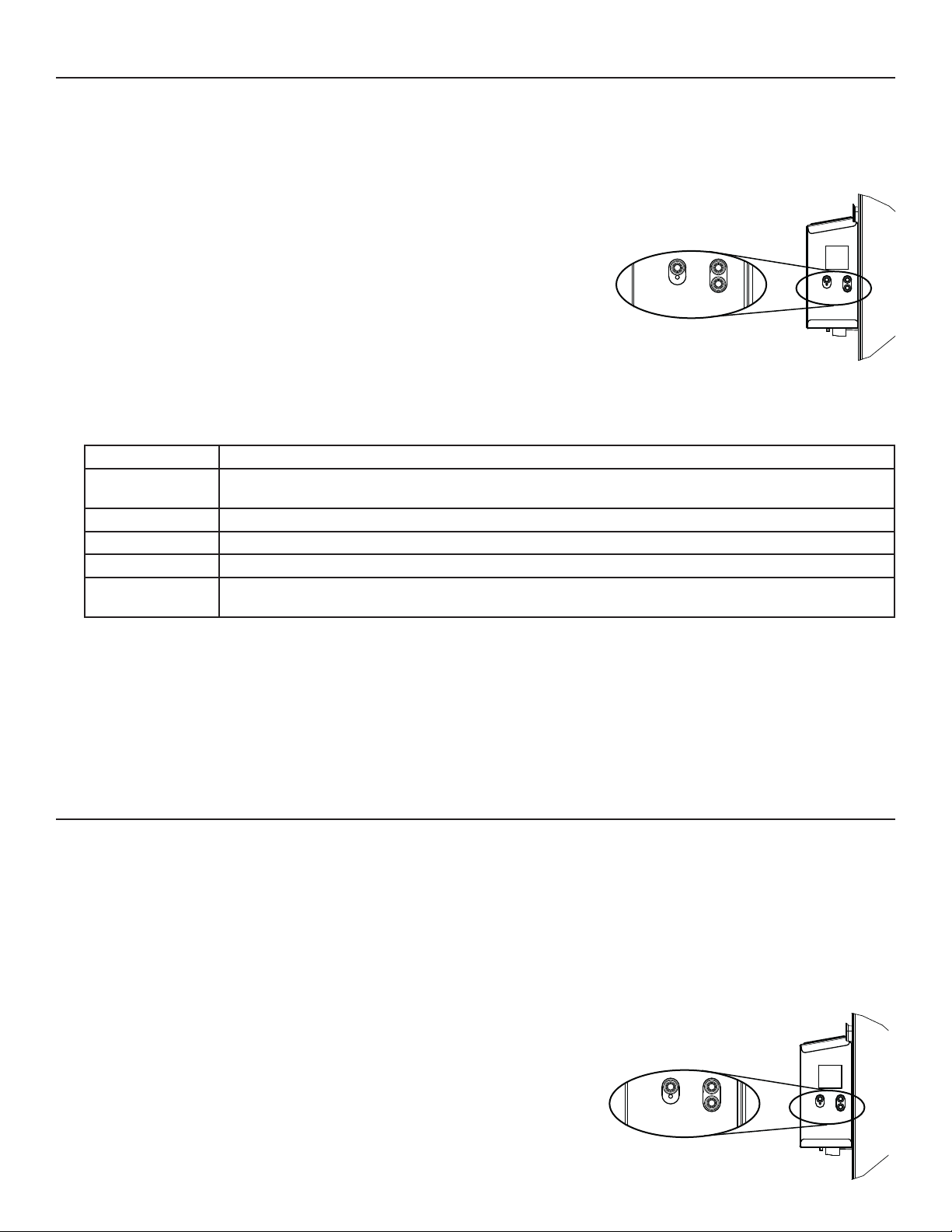
5. AUTO BALANCEO DEL APARATO
PREPARACIÓN
Siga estas indicaciones para mediciones precisas:
• Obture todos los conductos con cinta adhesiva. Cierre todas las ventanas y puertas.
• Apague todos los dispositivos de extracción, coma la campana de cocina, la secadora y los ventiladores del baño.
• Si la instalación está de alguna manera conectada a un conducto de un sistema central de aire forzado, asegúrese de
que el ventilador impelente del sistema central de aire forzado esté
encendido. De no ser así, deje el ventilador impelente del sistema central de aire
forzado apagado.
PROCEDIMIENTO DE AUTO BALANCEO
1. Enchufar el aparato y esperar hasta que el pi3/min máximo aparezca en la
pantalla LCD. Al primer proceso de arranque, necesitará más tiempo para obtener la
información puesto que los motores deben precalentar.
2. El pi3/min máximo aparacerá en la pantalla LCD. Utilizar (+/-) para ajustar el pi3/min y
OK para confi rmar.
3. El pi3/min mínimo aparacerá en la pantalla LCD. Utilizar (+/-) para ajustar el pi3/min y
OK para confi rmar.
4. INS aparacerá en la pantalla LCD. Elija entre T-1, T-2, T-3, T-4 o T-5 conforme a la
confi guración de instalación (consulte la sección 2.2 para más detalles).
5. Si es necesario, se pueden confi gurar opciones. En la pantalla CFG OPT, presionar el botón OK durante 4 segundos. Utilizar (+/-)
para cambiar la confi guración y OK para confi rmar. Si no es necesario, presionar OK para pasar este menú.
Opciones Con guraciones disponibles
DEF (Deshielo) DIS* (Discreción - deshielo sin variación de velocidad para mayor comodidad),
PLU (Plus - deshielo prolongado en un clima más frío).
INS (Instalación) T-1, T-2, T-3, T-4*, T-5 (consulte la sección 2.2)
DRY (Contacto seco) MIN* (Mínimo), INT (Intermitente), AUT (AUTO), MAX (Máximo) (consulte la sección 3.3.1)
OVR (Auxiliar) BAL* (Balanceado), PER (Rendimiento), DIS (Discreción) (consulte la sección 3.2.1)
INT (Intermitente) STB* (Espera - 20 min en modo MIN y 40 min en modo espera), REC** (Recirculación - 20 min en velocidad
MIN y 40 min en modo recirculación)
* Ajuste de fábrica
** La confi guración REC (Recirculación) no está disponible para los aparatos 150H75NT, 150H75NS, 150E75NT y 150E75NS.
6. El auto balanceo está completado.
NOTA: Si no se confi rma la selección dentro de 10 minutos, el aparato saldrá del menú sin guardar los cambios.
NOTA: Si la velocidad o la confi guración deben ser modifi cadas, acceder a MIN o MAX usando (+/-), después presionar el botón OK
durante 4 segundos. Utilizar (+/-) para aumentar/reducir la velocidad y OK para confi rmar.
Si se hace una modifi cación a los conductos, reinicializar los parámetros para reiniciar la prueba del fl ujo de aire.
VD0492
OK
+
-
PROCEDIMIENTO PARA REINICIALIZAR LOS PARÁMETROS
Presionar simultáneamente los botones OK y (-) durante 4 segundos. Utilizar (+/-) para seleccionar Yes o No y OK para confi rmar.
Después realizar el procedimiento de auto balanceo.
6. USO DE ESTE APARATO
6.1 SU SISTEMA DE VENTILACIÓN
Este aparato de ventilación balanceado está pensado para proporcionar aire fresco a su casa y extraer el aire viciado y húmedo. Gracias
a su unidad de recuperación de energía/de calor, el aparato recupera una gran proporción de la calor o energía que forma parte del aire
interior o exterior conforme a las estaciones para mejorar la comodidad y la efi ciencia energética durante los periodos de calentamiento y
de enfriamiento. Con Virtuo Air TechnologyTM, este aparato responde a las variaciones de su entorno de manera autónoma, garantizando
un nivel adecuado de ventilación y de calidad del aire. Este aparato ofrece también modos automáticos (AUTO o SMART) que gestionan
de manera autónoma el nivel de ventilación requerido conforme a las condiciones interiores y/o exteriores. En las zonas más frías, el
aparato realizará, a intervalos, un deshielo discreto de la unidad de recuperación para mantener rendimiento y comodidad.
6.2 CONTROL INTEGRADO
Todos los aparatos están equipados con un control integrado situado delante del compartimento eléctrico. Para mayor comodidad,
estos aparatos pueden controlarse mediante un control mural opcional o el termostato
del sistema central de aire forzado provisto con la activación del ventilador exterior.
SELECCIÓN DEL MODO
1. Para cambiar el modo, utilizar (+/-) para acceder a la pantalla modo. Presionar OK
para editar el modo y utilizar (+/-) para cambiar el modo (Standby, Min, Max).
2. Presionar OK para confi rmar la selección. Los pi3/min aparecerán en los dos modos
(MIN y MAX).
NOTA: Si un control mural auxiliar opcional o el termostato del sistema central de
aire forzado provisto con la activación del ventilador exterior se utiliza, eso invalida el
control integrado.
OK
VD0492
+
-
14
Page 37

7. PIEZAS DE RECAMBIO
D
E
B
C
H
I
P
G
F
J
O
K
L
M
N
VL0086
O
N
Puerto 6 pulg. lado caliente SV66139 2222
1
Puerto 5 pulg. lado caliente SV66140 2 2 2 2 2
Puerto de metal 6 pulg. compuerta motorizada SV66135 1111
2
Puerto de metal 5 pulg. compuerta motorizada SV66136 1 1 1 1 1
3 Conjunto electrónico SV66144** 111111111
4 Bloque de terminales SV66145 111111111
Conjunto puerto de escape 6 pulg. SV66137 1111
5
Conjunto puerto de escape 5 pulg. SV66138 1 1 1 1 1
6 Cerraduras y guardianes de puerta SV61218 111111111
7 Termistor SV66134 111111111
8 Compuerta de recirculación con termistor SV66148 1111111
9 Ventilador de evacuación con compuerta SV66142 111111111
10 Conjunto ventilador de alimentación SV66141 111111111
Núcleo ERV 65 % SV66113 1 1
Núcleo ERV 75 % SV66114 1 1
11
Núcleo HRV 65 % SV66115 1 1 1
Núcleo HRV 75 % SV66116 1 1
12 Kit de fi ltros MERV8 SV66133 111111111
13 Puerta SV66150 111111111
14 Compuerta de escape SV66143 111111111
15 Separador CE con termistor SV66149 1 1
* Bolsa de piezas SV66146 111111111
* Fusible para la tarjeta electrónica SV66147 111111111
* Conducto ½ pulg. SV00592 111111111
* No se muestra.
* *Consulte la página siguiente para obtener el número de pieza que corresponde al modelo del aparato de ventilación.
DESCRIPCIÓN
NúMERO DE
PIEZA
B110H65RT
B110H65RS
B130H65RT
B130H65RS
B130E65RT
B130E65RS
B160H65RT
B160H65RS
B160E65RT
B160E65RS
B160H75RT
B160H75RS
B160E75RT
B160E75RS
B150H75NT
B150H75NS
B150E75NT
B150E75NS
REPUESTOS Y REPARACIONES
Para que el aparato de ventilación
esté en buenas condiciones,
sólo debe utilizar repuestos
genuinos de Broan-NuTone
LLC. Los repuestos genuinos
de Broan-NuTone LLC han sido
diseñados especialmente para
cada aparato, se han fabricado
de conformidad con todas
las normas de certificación
aplicables y ofrecen un alto
nivel de seguridad. El uso de
repuestos diferentes puede
provocar daños graves y
reducir drásticamente el nivel
de rendimiento del aparato, lo
cual podría causar una avería
prematura. Broan-NuTone LLC
recomienda ponerse en contacto
con un almacén de servicio
certificado para todos los
repuestos y reparaciones.
15
Page 38
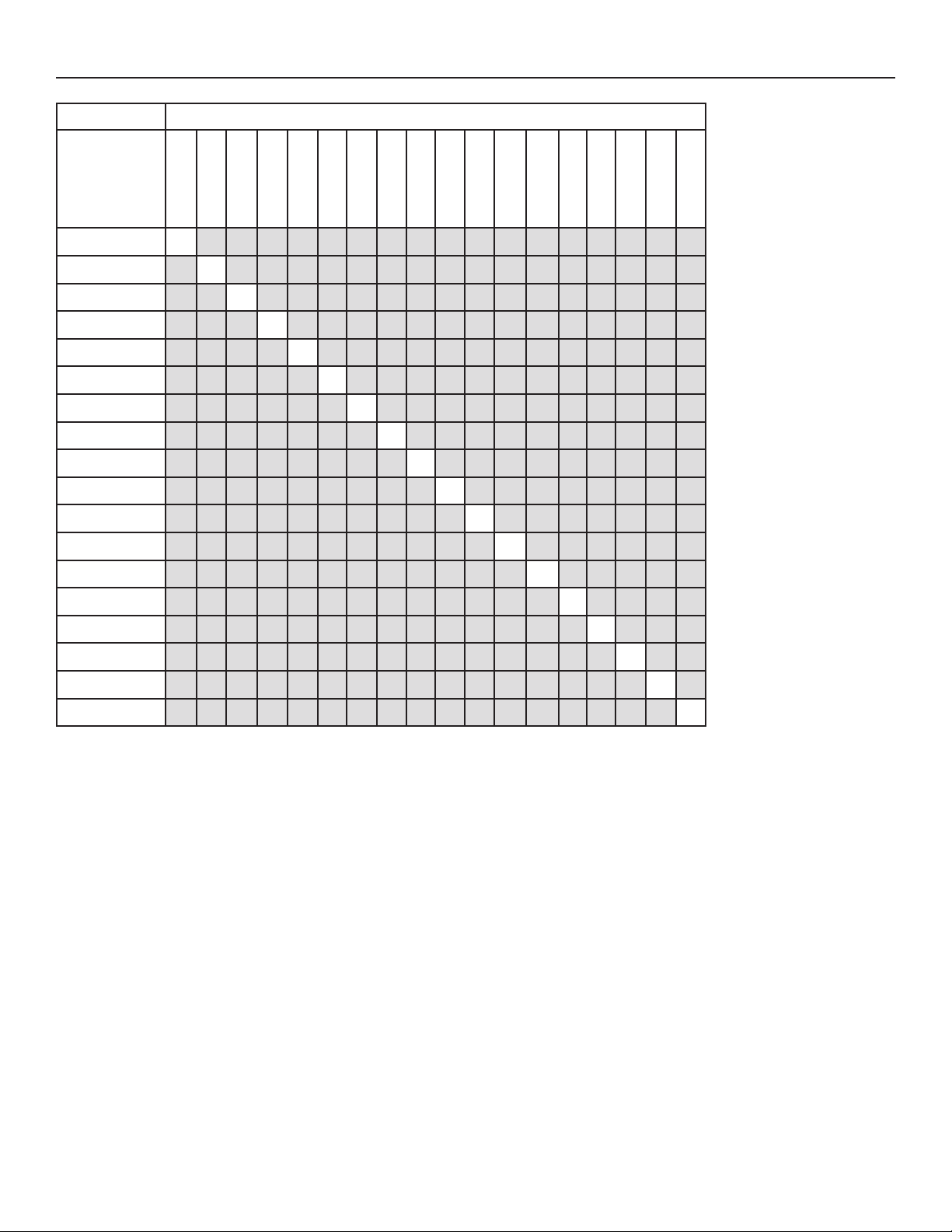
7. PIEZAS DE RECAMBIO (CONT.)
MODELO DEL APARATO DE VENTILACIÓN
NÚMERO DE
PIEZA DEL
CONJUNTO
ELECTRÓNICO
B110H65RS
B130H65RS
B110H65RT
B130H65RT
B160H65RT
B160H65RS
B150H75NS
B150H75NT
B160H75RS
SV66144-01 X
SV66144-02 X
SV66144-03 X
SV66144-04 X
SV66144-05 X
SV66144-06 X
SV66144-07 X
SV66144-08 X
SV66144-09 X
SV66144-10 X
B160H75RT
B130E65RS
B130E65RT
B160E65RS
B160E65RT
B150E75NS
B160E75RS
B150E75NT
B160E75RT
SV66144-11 X
SV66144-12 X
SV66144-13 X
SV66144-14 X
SV66144-15 X
SV66144-16 X
SV66144-17 X
SV66144-18 X
16
Page 39
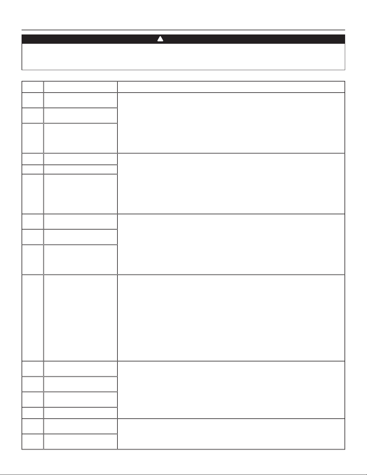
8. SOLUCIÓN DE PROBLEMAS DEL INSTALADOR
!
ADVERTENCIA
Se aconseja llevar guantes y gafas de protección porque algunos procedimientos de diagnóstico pueden exigir que el
aparato esté funcionando durante el procedimiento. Tenga cuidado con las piezas móviles y los componentes eléctricos
para evitar todo riesgo de lesiones.
ERROR DESCRIPCIÓN SOLUCIÓN
E01 Posición compuerta
alimentación
E02 Parada compuerta
alimentación
E03 Compuerta alimentación
E05 Posición compuerta salida ETAPA 1: Desenchufar el aparato, verifi car el sistema de compuertas, retirar
E06 Parada compuerta salida
E07 Compuerta salida
E09 Posición compuerta
recirculación
E10 Parada compuerta
recirculación
E11 Compuerta recirculación
E22 Flujo de aire alimentación ETAPA 1: Comprobar visualmente el sistema de compuertas de alimentación. Limpiar los
E23 Motor alimentación
(sobrecarga motor)
E27 Motor alimentación
(sobretensión motor)
E28 Motor alimentación
(duración motor)
E29 Motor alimentación (inicio)
ETAPA 1: Desenchufar el aparato, verifi car el sistema de compuertas, retirar
cualquier obstáculo indeseable o suciedad (puede ser necesario quitar los fi ltros y el núcleo
para acceder al sistema de compuertas). Enchufar el aparato.
Si la ETAPA 1 no arregló el problema, realizar la ETAPA 2: Abrir el compartimento eléctrico,
verifi car si el conector J5 (blanco) está bien insertado, verifi car si hay cables sueltos.
Si la ETAPA 2 no arregló el problema, realizar la ETAPA 3: Si la compuerta no se mueve,
desenchufar J7 (rojo) de la tarjeta electrónica, conectar el conector blanco del sistema de
compuertas en J7. Si la compuerta mueve (el sistema sigue indicando un error), reemplazar
el conjunto electrónico. Si no funciona, reemplazar el sistema de compuertas.
cualquier obstáculo indeseable o suciedad (puede ser necesario quitar los fi ltros y el núcleo
para acceder al sistema de compuertas). Enchufar el aparato.
Si la ETAPA 1 no arregló el problema, realizar la ETAPA 2: Abrir el compartimento eléctrico,
verifi car si el conector J7 (rojo) está bien insertado, verifi car si hay cables sueltos.
Si la ETAPA 2 no arregló el problema, realizar la ETAPA 3: Si la compuerta no se mueve,
desenchufar J5 (blanco) de la tarjeta electrónica, conectar el conector blanco del sistema de
compuertas en J5. Si la compuerta mueve (el sistema sigue indicando un error), reemplazar
el conjunto electrónico. Si no funciona, reemplazar el sistema de compuertas.
ETAPA 1: Desenchufar el aparato, verifi car el sistema de compuertas, retirar
cualquier obstáculo indeseable o suciedad (puede ser necesario quitar los fi ltros y el núcleo
para acceder al sistema de compuertas). Enchufar el aparato.
Si la ETAPA 1 no arregló el problema, realizar la ETAPA 2: Abrir el compartimento eléctrico,
verifi car si el conector J6 (azul) está bien insertado, verifi car si hay cables sueltos.
Si la ETAPA 2 no arregló el problema, realizar la ETAPA 3: Si la compuerta no se mueve,
desenchufar J5 (blanco) de la tarjeta electrónica, conectar el conector azul del sistema de
compuertas en J5. Si la compuerta mueve (el sistema sigue indicando un error), reemplazar
el conjunto electrónico. Si no funciona, reemplazar el sistema de compuertas.
fi ltros, los registros de distribución y las bocas de admisión exterioras. Inspeccionar los
conductos para asegurarse que no están comprimidos o doblados.
Si la ETAPA 1 no arregló el problema, realizar la ETAPA 2: Retirar los conductos de la línea de
alimentatión. En la pantalla LCD, seleccionar MAX para verifi car si el aparato puede lograr el
fl ujo seleccionado. En caso de que así sea, verifi car la línea de los conductos.
Si la ETAPA 2 no arregló el problema, realizar la ETAPA 3: En la pantalla LCD, seleccionar los
valores de ajuste de los fl ujos MIN y MAX y después reinicializar el aparato. El valor de fl ujo
MAX aparecerá en la pantalla LCD. Si el fl ujo MAX es superior al fl ujo MAX deseado, ajustar
los fl ujos MAX y MIN.
Si la ETAPA 3 no arregló el problema, realizar la ETAPA 4: Reemplazar el ventilador de
alimentación y repetir la ETAPA 3.
Si la ETAPA 4 no arregló el problema, realizar la ETAPA 5: Reemplazar el conjunto electrónico.
ETAPA 1: Desenchufar/enchufar el aparato.
Si la ETAPA 1 no arregló el problema, realizar la ETAPA 2: Quitar el núcleo y retirar cualquier
obstáculo o suciedad de la rueda de ventilación.
Si la ETAPA 2 no arregló el problema, realizar la ETAPA 3: Desconectar J2 (blanco) y conectar
un sistema de ventilador de repuesto. Si funciona, reemplazar el ventilador de alimentación.
Si la ETAPA 3 no arregló el problema, realizar la ETAPA 4: Reemplazar el conjunto
electrónico.
E24 Motor alimentación
(sobretensión motor)
E25 Motor alimentación
(subtensión motor)
ETAPA 1: Desenchufar/enchufar el aparato. Sobretensión y subtensión se pueden observar
con una fuerte fl uctuación de la alimentación eléctrica de la casa y se pueden apagar el
motor para protegerlo.
Si la ETAPA 1 no arregló el problema, realizar la ETAPA 2: Reemplazar el conjunto electrónico.
17
Page 40
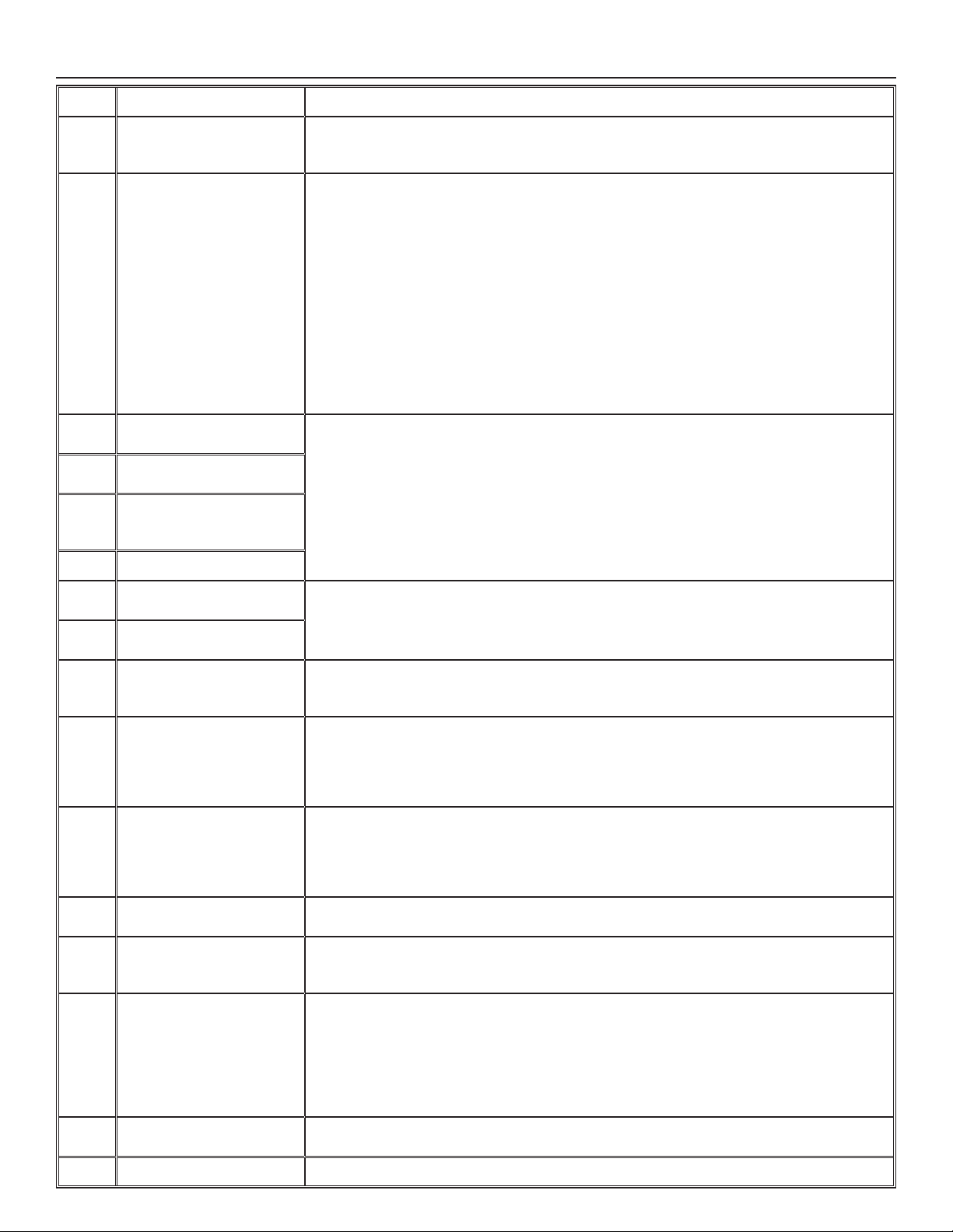
8. SOLUCIÓN DE PROBLEMAS DEL INSTALADOR (CONT.)
ERROR DESCRIPCIÓN SOLUCIÓN
E26 Motor alimentación
(sobrecalentamiento
motor)
E32 Flujo de aire a la salida ETAPA 1: Comprobar visualmente el sistema de compuertas de salida. Limpiar los fi ltros, los
E33 Motor a la salida
(sobrecarga motor)
E37 Motor a la salida
(duración motor)
E38 Motor a la salida
(retroalimentación
velocidad motor)
E39 Motor a la salida (inicio)
ETAPA 1: Validar si el intercambiador de aire es expuesto a temperaturas ambiente dentro
de los límites de funcionamiento (ver p. 4)
Si la ETAPA 1 no arregló el problema, realizar la ETAPA 2: Reemplazar el conjunto electrónico.
registros de distribución y las bocas de admisión exterioras. Inspeccionar los conductos para
asegurarse que no están comprimidos o doblados.
Si la ETAPA 1 no arregló el problema, realizar la ETAPA 2: Retirar los conductos de la línea de
alimentatión. En la pantalla LCD, seleccionar MAX para verifi car si el aparato puede lograr el
fl ujo seleccionado. En caso de que así sea, verifi car la línea de los conductos.
Si la ETAPA 2 no arregló el problema, realizar la ETAPA 3: En la pantalla LCD, seleccionar los
valores de ajuste de los fl ujos MIN y MAX y después reinicializar el aparato. El valor de fl ujo
MAX aparecerá en la pantalla LCD. Si el fl ujo MAX es superior al fl ujo MAX deseado, ajustar
los fl ujos MAX y MIN.
Si la ETAPA 3 no arregló el problema, realizar la ETAPA 4: Reemplazar el ventilador de salida
y repetir la ETAPA 3.
Si la ETAPA 4 no arregló el problema, realizar la ETAPA 5: Reemplazar el conjunto
electrónico.
ETAPA 1: Desenchufar/enchufar el aparato.
Si la ETAPA 1 no arregló el problema, realizar la ETAPA 2: Quitar el núcleo y retirar cualquier
obstáculo o suciedad de la rueda de ventilación.
Si la ETAPA 2 no arregló el problema, realizar la ETAPA 3: Desconectar J3 (rojo) y conectar un
sistema de ventilador de repuesto. Si funciona, reemplazar el ventilador de salida.
Si la ETAPA 3 no arregló el problema, realizar la ETAPA 4: Reemplazar el conjunto electrónico.
E34 Motor a la salida
(sobretensión motor)
E35 Motor a la salida
(subtensión motor)
E36 Motor a la salida
(sobrecalentamiento
motor)
E40 Termistor aire exterior ETAPA 1: Verifi car si el termistor está bien conectado en el conector J7A.
E41 Termistor distribución del
aire
E42 Termistor conjunto tarjeta
electrónica
E43 Temperatura tarjeta
electrónica supera el límite
E50 Pérdida comunicación con
el control
E51 Sensor control mural ETAPA 1: Desenchufar el aparato, comprobar los cables, enchufar el aparato.
E60 Modo protección ETAPA 1: Realizar una inspección general del aparato (compuertas, núcleo, fi ltros).
ETAPA 1: Desenchufar/enchufar el aparato. Sobretensión y subtensión se pueden observar
con una fuerte fl uctuación de la alimentación eléctrica de la casa y se pueden apagar el
motor para protegerlo.
Si la ETAPA 1 no arregló el problema, realizar la ETAPA 2: Reemplazar el conjunto electrónico.
ETAPA 1: Validar si el intercambiador de aire es expuesto a temperaturas ambiente dentro
de los límites de funcionamiento (ver p. 4)
Si la ETAPA 1 no arregló el problema, realizar la ETAPA 2: Reemplazar el conjunto electrónico.
Si la ETAPA 1 no arregló el problema, realizar la ETAPA 2: Desconectar conector J7A y
verifi car si la resistencia medida (conector del termistor) es dentro de
5 Kohms a 120 Kohms. Si está fuera del rango, reemplazar el termistor.
Si la ETAPA 2 no arregló el problema, realizar la ETAPA 3: Reemplazar el conjunto electrónico.
ETAPA 1: Verifi car si el termistor está bien conectado en el conector J7B.
Si la ETAPA 1 no arregló el problema, realizar la ETAPA 2: Desconectar conector J7B y
verifi car si la resistencia medida (conector del termistor) es dentro de
5 Kohms a 120 Kohms. Si está fuera del rango, reemplazar el termistor.
Si la ETAPA 2 no arregló el problema, realizar la ETAPA 3: Reemplazar el conjunto electrónico.
ETAPA 1: Reemplazar el conjunto electrónico.
ETAPA 1: Validar si el intercambiador de aire es expuesto a temperaturas ambiente dentro
de los límites de funcionamiento (ver p. 4)
Si la ETAPA 1 no arregló el problema, realizar la ETAPA 2: Reemplazar el conjunto electrónico.
ETAPA 1: Desenchufar el aparato, comprobar los cables, enchufar el aparato.
Si la ETAPA 1 no arregló el problema, realizar la ETAPA 2: Retirar el control mural de la pared
y probar con un cable corto. Si funciona, llevar un nuevo cable a la ubicación de instalación
en la pared.
Si la ETAPA 2 no arregló el problema, realizar la ETAPA 3: Probar el intercambiador de aire
con un control mural de repuesto. Si funciona, reemplazar el control mural.
Si la ETAPA 3 no arregló el problema, realizar la ETAPA 4: Reemplazar el conjunto electrónico.
Si la ETAPA 1 no arregló el problema, realizar la ETAPA 2: Reemplazar el control mural.
18
Page 41

8. SOLUCIÓN DE PROBLEMAS DEL INSTALADOR (CONT.)
ADVERTENCIA DESCRIPCIÓN SOLUCIÓN
W22 Flujo de aire
alimentación
W32 Flujo de aire a
la salida
W52 Con guración
inicial
incompleta
W61
Modo protección
sobrecalentamiento
del sistema
electrónico
ETAPA 1: Comprobar visualmente el sistema de compuertas de alimentación. Limpiar los fi ltros,
los registros de distribución y las bocas de admisión exterioras. Inspeccionar los conductos para
asegurarse que no están comprimidos o doblados.
Si la ETAPA 1 no arregló el problema, realizar la ETAPA 2: Retirar los conductos de la línea de
alimentatión. En la pantalla LCD, seleccionar MAX para verifi car si el aparato puede lograr el
fl ujo seleccionado. En caso de que así sea, verifi car la línea de los conductos.
Si la ETAPA 2 no arregló el problema, realizar la ETAPA 3: En la pantalla LCD, seleccionar los
valores de ajuste de los fl ujos MIN y MAX y después reinicializar el aparato. El valor de fl ujo MAX
aparecerá en la pantalla LCD. Si el fl ujo MAX es superior al fl ujo MAX deseado, ajustar los fl ujos
MAX y MIN.
Si la ETAPA 3 no arregló el problema, realizar la ETAPA 4: Reemplazar el ventilador de
alimentación y repetir la ETAPA 3.
Si la ETAPA 4 no arregló el problema, realizar la ETAPA 5: Reemplazar el conjunto electrónico.
ETAPA 1: Comprobar visualmente el sistema de compuertas de salida. Limpiar los fi ltros, los
registros de distribución y las bocas de admisión exterioras. Inspeccionar los conductos para
asegurarse que no están comprimidos o doblados.
Si la ETAPA 1 no arregló el problema, realizar la ETAPA 2: Retirar los conductos de la línea de
alimentatión. En la pantalla LCD, seleccionar MAX para verifi car si el aparato puede lograr el
fl ujo seleccionado. En caso de que así sea, verifi car la línea de los conductos.
Si la ETAPA 2 no arregló el problema, realizar la ETAPA 3: En la pantalla LCD, seleccionar los
valores de ajuste de los fl ujos MIN y MAX y después reinicializar el aparato. El valor de fl ujo MAX
aparecerá en la pantalla LCD. Si el fl ujo MAX es superior al fl ujo MAX deseado, ajustar los fl ujos
MAX y MIN.
Si la ETAPA 3 no arregló el problema, realizar la ETAPA 4: Reemplazar el ventilador de salida y
repetir la ETAPA 3.
Si la ETAPA 4 no arregló el problema, realizar la ETAPA 5: Reemplazar el conjunto electrónico.
ETAPA 1: Presionar el botón + o - para acceder al menu selección.
ETAPA 2: Completar la confi guración. (Consulte la sección 5 para más detalles).
El aparato está en modo protección. La potencia transmitida al motor se reduce
voluntariamente para disminuir la temperatura del sistema electrónico. El aparato saldrá de este
modo por sí mismo una vez que las condiciones vuelvan a la normalidad. Es normal observar
una reducción en los fl ujos de aire durante este periódo. Esta condición debe aparecer sólo
cuando el aparato está situado en un ambiente cálido, por ejemplo más de 60°C (140°F). Si
esta condición aparece mientras que el aparato está situado en un lugar donde la temperatura
ambiente está debajo de 30°C (86°F), reemplazar el conjunto electrónico.
19
Page 42
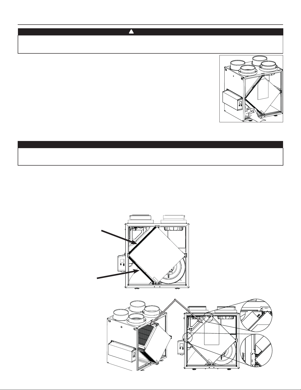
9. MANTENIMIENTO
!
ADVERTENCIA
Riesgo de alta tensión. Durante las operaciones de mantenimiento o de reparación, el aparato debe estar siempre
apagado y desenchufado para evitar todo riesgo de choque eléctrico. Se aconseja llevar guantes y gafas de protección al
manipular los componentes del aparato para evitar todo riesgo de lesiones causadas por la presencia de metal delgado.
9.1 TRIMESTRAL
1. Desconecte el cable de alimentación.
2. La puerta de este aparato lleva bisagras y se mantiene cerrada con 2 cerraduras. Retírelas y póngalas
a un lado.
3. Limpie el interior de la puerta con un paño húmedo.
4. Limpie los fi ltros:
• Quite los fi ltros.
• Pase una aspiradora para quitar la mayor parte del polvo.
• Lávelos con una mezcla de agua tibia y jabón suave. Puede añadir lejía si desea desinfectar (una
cucharada por galón). Enjuague a fondo. Agite los fi ltros para eliminar el exceso de agua y déjelos
secar.
Nota: El fi ltro opcional MERV13 es un fi ltro desechable. El fi ltro debe ser reemplazado cuando está demasiado sucio.
5. Limpie la placa de condensación con un paño húmedo.
6. Verifi que la boca de entrada de aire del exterior:
PRECAUCIÓN
Un orifi cio de ventilación o un fi ltro bloqueado, aunque sólo sea parcialmente, puede hacer que el aparato funcione mal.
El confort que ofrece el aparato podría reducirse y la probabilidad de que se congele el aparato podría aumentar. Podrían
resultar una rotura del aparato y/o daños a los bienes.
• Compruebe que no haya hojas, ramitas, hielo o nieve que podrían entrar en el aparato.
• Limpie si es necesario.
7. Vuelva a montar los componentes. Preste atención especialmente a los fi ltros y compruebe que están bien encajados en sus ranuras.
8. Gire las ruedas del ventilador impelente a mano. Si una de las ruedas no gira normalmente, póngase en contacto con su instalador.
9. Cierre la puerta y vuelva a conectar la fuente de alimentación.
10. Reinicializar los fi ltros, si es necesario. Si utiliza un control mural principal opcional (SELECTOR DE VELOCIDAD, DEHUMIDOSTATO O AUTOMÁTICO),
presionar el botón INT/AUTO durante 5 segundos para reinicializar los fi ltros. Si utiliza el control mural principal opcional Avanzado, siga
las instrucciones en la pantalla táctil.
VD0493
FILTRO MERV8 INCLUIDO
F
ILTRO DE SALIDA INCLUIDO
Tirar el núcleo de 3 a 4 pulg.
hacia fuera.
Instalar el fi ltro MERV13 sobre
el núcleo, como se ilustra.
Empujar el núcleo y el fi ltro
MERV13 al fondo del aparato.
NOTA: El fi ltro opcional MERV13 reemplaza
el fi ltro MERV8.
FILTRO MERV13 OPCIONAL (FILTRO DE SALIDA NO INCLUIDO)
20
Page 43
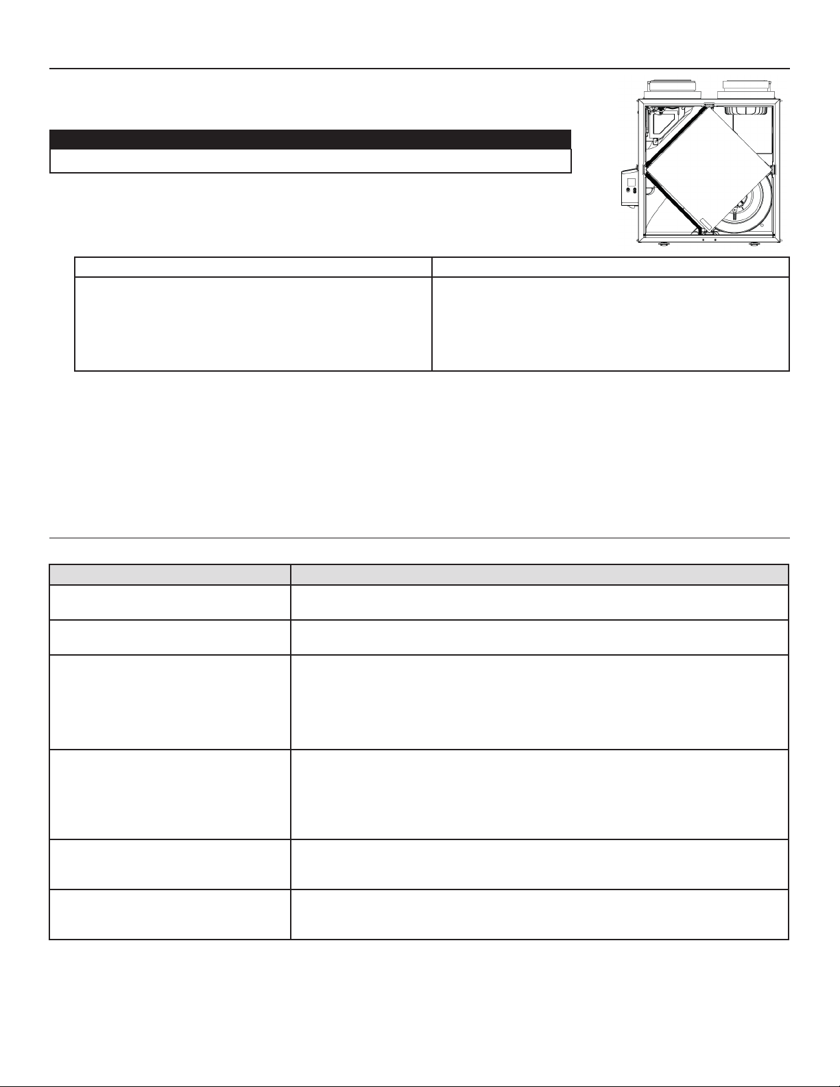
9. MANTENIMIENTO (CONT.)
9.2 ANUAL (EN OTOÑO)
1. Repita las etapas 1 a 6 de la sección anterior y continúe con las que se exponen a continuación:
PRECAUCIÓN
• Manipule con cuidado el núcleo.
2. Limpie el núcleo:
MODELOS HRV MODELOS ERV
• Retire el núcleo.
• Déjelo en remojo en una mezcla de agua fría o tibia y jabón
suave (detergente para vajillas).
• Enjuague a fondo.
• Agite el núcleo para eliminar el exceso de agua y déjelo
secar.
3. Limpie el conjunto del ventilador impelente. No desmonte el conjunto del ventilador.
4. Quite el polvo con una aspiradora equipada con un cepillo suave.
5. Vuelva a montar los componentes.
6. Vuelva a conectar la fuente de alimentación.
Quite el polvo del núcleo con una aspiradora equipada con un
cepillo suave.
PRECAUCIÓN: NO SUMERJA EN AGUA EL NÚCLEO.
VD0494
10. SOLUCIÓN DE PROBLEMAS POR PARTE DEL USUARIO
Póngase en contacto con el servicio de atención al cliente en el teléfono 1-800-558-1711 para cualquier problema no resuelto.
PROBLEMA INTENTE ESTO
1. Nada funciona. • Verifi que si el aparato está enchufado.
• Compruebe si el aparato recibe alimentación del disyuntor o del fusible de la casa.
2. Aparato ruidoso. • Limpie el aparato (véase la sección 9). Si el problema no se soluciona, póngase en
contacto con el instalador.
3. Condensación en las ventanas en caso
de bajas temperaturas.
4. Humedad en el interior en caso de
tiempos calientes/húmedos.
5. Aire demasiado seco. • Haga funcionar el aparato a velocidad MIN.
6. Aire demasiado frío en la rejilla de
suministro de aire.
• Haga funcionar el aparato a velocidad MAX durante las actividades que generan
humedad excesiva (reuniones familiares, mucha cocina, etc.).
• Deje las cortinas entreabiertas para que el aire circule.
• Guarde toda la leña en un cuarto cerrado equipado con un deshumidifi cador, en un
cuarto bien ventilado o en el exterior.
• Mantenga la temperatura de su casa por encima de 64°F.
• Haga funcionar el aparato a velocidad MIN.
• Cambie temporalmente al modo INT (si está disponible).
• Use un deshumidifi cador.
• Cambie temporalmente al modo INT (si está disponible).
• Use temporalmente un humidifi cador.
• Asegúrese de que las bocas exterioras no están bloqueadas.
• Haga funcionar el aparato a velocidad MIN.
• Instale un calentador de conductos (póngase en contacto con su instalador).
21
Page 44

11. GARANTÍA
Este aparato de ventilación de Broan es un producto de gran calidad, fabricado y empacado con cuidado.
Broan garantiza al comprador original de sus productos que dichos productos están libres de defectos por el periodo de tiempo
indicado
más adelante, a partir de la fecha de compra original. La garantía de todos los aparatos Broan cubre las piezas únicamente contra
cualquier defecto que pudiera perjudicar su funcionamiento. Su duración es de cinco (5) años. A reserva de que se efectúe el
mantenimiento del núcleo, tal y como se indica en el manual del usuario y del instalador, el núcleo de recuperación del calor (HRV)
tiene una garantía limitada de por vida, y el núcleo de recuperación de energía (ERV) tiene una garantía de cinco (5) años. Si el aparato
funcionara de manera inadecuada, consulte el manual del usuario y del instalador. Si el problema continúa, siga estos pasos:
PROCEDIMIENTO A SEGUIR
Si el aparato estuviera defectuoso, sírvase comunicar inmediatamente con su empresa de ventilación (véase la dirección en la cubierta de
este manual). La empresa determinará el origen del mal funcionamiento del aparato y lo sustituirá o reparará, de ser necesario.
Si le resultara imposible ponerse en comunicación con la empresa, telefonee (en América del Norte) al 1-800-558-1711 y nuestro
personal le indicará con mucho gusto el teléfono del distribuidor o del centro de servicio más próximo.
REPLACEMENT PARTS AND REPAIR
Para que el aparato funcione bien debe usar siempre piezas originales de Broan. Estas piezas se han diseñado especialmente para
cumplir con todas las normas de certifi cación de seguridad aplicables. El uso de piezas diferentes podría poner en peligro la seguridad
del aparato, ocasionar una reducción importante de su funcionamiento y producir una falla prematura. Broan también aconseja
consultar siempre con una empresa de servicios competente reconocida por Broan para las piezas de recambio y para solicitar un
servicio.
FACTURA
La garantía no cubrirá ninguna reparación ni sustitución sin la factura original de compra. Le rogamos, pues, que la conserve debidamente.
GASTOS VARIOS
En cada caso, los gastos de mano de obra para retirar una pieza defectuosa o instalar una pieza conforme no estarán cubiertos por el
fabricante.
CONDICIONES Y LÍMITES
Este aparato es pensados únicamente para uso residencial y han de utilizarse en un edifi cio tal y como se describe a continuación:
Edifi cio: Toda construcción usada o destinada para ser usada con el fi n de alojar o recibir personas, animales o cosas.
Uso residencial: Vivienda, alojamiento, suite: edifi cio o parte de un edifi cio que sirve o está destinado a servir de domicilio a una o varias
personas y que también posee instalaciones sanitarias, para preparar y consumir comidas y dormir. Local constituido
por una sola pieza o un grupo de piezas complementarias y ocupado por un inquilino o propietario; incluye los
alojamientos, las habitaciones individuales de moteles, hoteles, las casas de alquiler de habitaciones, los dormitorios
colectivos y las pensiones familiares, incluso las tiendas y los establecimientos de negocios de una sola pieza en una
vivienda.
Uso comercial: Establecimiento agrícola, comercial, de reunión, de cuidados o de detención: edifi cio o parte de un edifi cio que no
contenga viviendas, situado en un terreno dedicado a la agricultura o a la ganadería y usado fundamentalmente para
guardar equipos o animales, o para la producción, almacenamiento o tratamiento de productos agrícolas u hortícolas o la
alimentación de los animales. Edifi cio o parte de un edifi cio usado para colocar o vender mercancías o productos al por
menor o usado para realizar negocios o prestar servicios profesionales o personales. Edifi cio o parte de un edifi cio
usado por personas que se reúnen para realizar actividades cívicas, políticas, turísticas, religiosas, mundanas, educativas,
recreativas o similares, o para consumir alimentos o bebidas. Edifi cio o parte de un edifi cio que acoge a personas
que, por su estado físico o mental, necesitan cuidados o tratamientos médicos, o a personas que, por razones de
seguridad fuera de su control, no pueden guarecerse en caso de peligro.
Uso industrial: Edifi cio o parte de un edifi cio usado para ensamblar, fabricar, confeccionar, tratar, reparar o almacenar productos,
materias o materiales cuyo contenido es combustible y posee materias muy combustibles, infl amables o explosivas en
cantidad sufi ciente para constituir un riesgo concreto de incendio.
La garantía se aplicará en todos los casos en los que los daños no resulten de una instalación inadecuada, de un uso inapropiado, de un
abuso o negligencia, de un caso fortuito o de cualquier otra circunstancia fuera del control de Broan. Además, Broan no se hace responsable
de las lesiones o daños en la propiedad personal o inmobiliaria causados directa o indirectamente por el aparato de ventilación Broan.
Esta garantía anula todas las garantías anteriores.
Broan 926 West State Street, Hartford, WI 53027 www.broan.com 800-558-1711
22
 Loading...