

Broan 88000 SERIES, COMBIFLASH250 Installation Instructions Manual
88000 SERIES/MICROTEK® SYSTEM IV
CONVERTIBLE RANGE HOOD
INSTALLATION INSTRUCTIONS
READ AND SAVE
THESE INSTRUCTIONS
For Ductfree Installation:
purchase a 97007662 Microtek
Kit, available from your Broan Distributor or online
at www.broan.com.
Follow all general steps and:
®
System IV Filter
SERIE 88000/MICROTEK® SISTEMA IV
INSTRUCCIONES PARA INSTALACION
DE CAPUCHA PARA ESTUFA
ELECTRICA CONVERTIBLE
LEA Y CONSERVE
ESTAS INSTRUCCIONES
Para instalación sin conductos:
compre un juego de filtro 97007662 Microtek
disponible por parte de su distribuidor Broan o en línea en
www.broan.com.
Siga todos los pasos generales y:
®
Sistema IV,
INTENDED FOR DOMESTIC
COOKING ONLY.
WARNING
TO REDUCE THE RISK OF FIRE, ELECTRIC SHOCK, OR
INJURY TO PERSONS, OBSERVE THE FOLLOWING:
1. Use this unit only in the manner intended by the manufacturer. If you have questions, contact the manufacturer
at the address or telephone number listed in the warranty.
2. Before servicing or cleaning unit, switch power off at
service panel and lock the service disconnecting means
to prevent power from being switched on accidentally.
When the service disconnecting means cannot be locked,
securely fasten a prominent warning device, such as a tag,
to the service panel.
3. Installation work and electrical wiring must be done by a
qualified person(s) in accordance with all applicable codes
and standards, including fire-rated construction codes and
standards.
4. Sufficient air is needed for proper combustion and exhausting of gases through the flue (chimney) of fuel burning
equipment to prevent backdrafting. Follow the heating
equipment manufacturer’s guideline and safety standards
such as those published by the National Fire Protection
Association (NFPA), and the American Society for Heating,
Refrigeration and Air Conditioning Engineers (ASHRAE),
and the local code authorities.
5. When cutting or drilling into wall or ceiling, do not damage
electrical wiring and other hidden utilities.
6. To reduce the risk of fire or electric shock, do not use this
range hood with an additional speed control device.
7. Ducted fans must always be vented to the outdoors.
8. To reduce the risk of fire, use only metal ductwork.
9. Use with approved cord-connection kit only.
10. This unit must be grounded.
TO REDUCE THE RISK OF A RANGE TOP GREASE FIRE:
1. Never leave surface units unattended at high settings.
Boilovers cause smoking and greasy spillovers that may
ignite. Heat oils slowly on low or medium settings.
2. Always turn hood ON when cooking at high heat or when
cooking flaming foods.
3. Clean ventilating fans frequently. Grease should not be
allowed to accumulate on fan or filter.
4. Use proper pan size. Always use cookware appropriate
for the size of the surface element.
TO REDUCE THE RISK OF INJURY TO PERSONS IN THE
EVENT OF A RANGE TOP GREASE FIRE, OBSERVE THE
FOLLOWING:*
1. SMOTHER FLAMES with a close-fitting lid, cookie sheet,
or metal tray, then turn off the burner. BE CAREFUL TO
PREVENT BURNS. If the flames do not go out immediately, EVACUATE AND CALL THE FIRE DEPARTMENT.
2. NEVER PICK UP A FLAMING PAN — You may be burned.
3. DO NOT USE WATER, including wet dishcloths or towels
- violent steam explosion will result.
4. Use an extinguisher ONLY if:
A. You know you have a Class ABC extinguisher and
you already know how to operate it.
B. The fire is small and contained in the area where it
started.
C. The fire department is being called.
D. You can fight the fire with your back to an exit.
* Based on “Kitchen Fire Safety Tips” published by NFPA.
Register your product online at: www.broan.com/register
Registre su producto en línea en: www.broan.com/register
PREVISTO PARA COCINAR
DOMÉSTICO SOLAMENTE.
ADVERTENCIA
PARA REDUCIR EL RIESGO DE INCENDIO, DESCARGA ELECTRICA, O LESIONES PERSONALES, CUMPLA CON LOS
SIGUIENTES PUNTOS:
1. Solamente use esta unidad de la manera propuesta por el
fabricante. Si tiene alguna pregunta, póngase en contacto con
el fabricante en la dirección o teléfono anotados en la garantía.
2. Antes de limpiar o de poner en servicio la unidad, apague
el interruptor en el panel de servicio, y asegure el panel de
servicio para evitar que se encienda accidentalmente. Cuando
el dispositivo para desconectar el servicio eléctrico no puede
ser cerrado con algún tipo de traba, sujete fuertemente al panel
de servicio, una etiqueta de advertencia prominente.
3. El trabajo de instalación y el cableado eléctrico deben llevarse a
cabo por personal calificado de acuerdo con todos los códigos
y las normas aplicables, incluyendo los códigos y normas de
construcción contra incendios.
4. Se requiere una cantidad de aire suficiente para la combustión
y escape de gases por la chimenea del equipo que quema
combustible para evitar la retrogresión de la llama. Siga las
especificaciones y estándares de seguridad del fabricante,
tales como los que publica la Asociación Nacional de Protección
Contra Incendios (NFPA por sus sigles en inglés), y la Sociedad
Americana de Ingenieros de Calefacción , Refrigeración y Aire
Acondicionado (ASHRAE), y los códigos de las autoridades
locales.
5. Cuando corte o taladre en una pared o cielo raso, no dañe
cableado eléctrico u otras instalaciones no visibles.
6. Para reducir el riesgo de incendio o de descarga eléctrica, no
utilice este ventilador con ningún dispositivo de una control de
velocidad de estado sólido adicional.
7. Los abanicos con ducto deberán siempre tener una salida hacia
el exterior.
8. Para reducir el riesgo de incendio, use sólo ductos de metal.
9. Uso con el kit aprobado del la conexión de la cuerda solamente.
10. Esta unidad se debe instalar con tierra efectiva.
PARA REDUCIR EL RIESGO DE INCENDIO DEBIDO A GRASA
ACUMULADA EN LAS HORNILLAS:
1. Nunca deje sin atender las unidades de superficie cuando
tengan ajustes altos. Los reboses pueden provocar humo
y derrames grasosos que se pueden incendiar. Caliente
lentamente el aceite en un ajuste bajo o medio.
2. Siempre ENCIENDA la campana cuando cocine con alta
temperatura o cuando cocine alimentos que se puedan
incendiar.
3. Limpie con frecuencia los ventiladores. No debe permitir que
la grasa se acumule en el ventilador ni en el filtro.
4. Utilice un sartén de tamaño adecuado. Siempre utilice el
utensilio adecuado al tamaño del elemento de superficie.
PARA REDUCIR EL RIESGO DE LESIONES PERSONALES EN
CASO DE INCENDIO DE GRASA EN LA SUPERFICIE DE LA
ESTUFA, OBSERVAR LO SIGUIENTE:*
1. Cubra y sofoque las llamas con una tapa ajustada, azafate
de hornear galletas, o un azafate de metal, y luego apague el
calentador. TENGA CUIDADO PARA EVITAR QUEMADURAS.
Si las llamas no se apagan inmediatamente, HAY QUE
EVACUAR Y LLAMAR LOS BOMBEROS.
2. NUNCA ALCE UNA SARTEN QUE TENGA LLAMAS - Usted
se puede quemar.
3. NO USE AGUA, incluyendo trapos lavaplatos mojados o toallas
- puede que ocurran explosiones de vapor violentas.
4. Use un extintor SOLAMENTE si:
A. usted sabe que tiene un extintor ABC y ya sabe usarlo.
B. el fuego es pequeño y está restringido al área donde
empezó.
C. se está llamando los bomberos.
D. usted puede tratar de apagar el fuego teniendo una salida
detrás suyo.
* Basado en "Kitchen Fire Safety Tips" publicado por la Asociación
Nacional de Protección Contra Incendios (NFPA).
INSTALLER: Leave This Manual With The Homeowner. HOMEOWNER: Use and Care Information on Page 5.
INSTALADOR: Deje este manual con el dueño de casa. DUEÑO DE CASA: Información del uso y mantenimiento en la página 6.
CAUTION
1. For indoor use only.
2. For general ventilating use only. Do not use to
exhaust hazardous or explosive materials and
vapors.
3. To avoid motor bearing damage and noisy and/
or unbalanced impellers, keep drywall spray,
construction dust, etc. off power unit.
4. This product is equipped with a thermostat which
may start fan automatically. To reduce the risk of
injury, switch power off at service panel and lock
service panel to prevent power from being switched
on automatically.
5. Your hood motor has a thermal overload which
will automatically shut off the motor if it becomes
overheated. The motor will restart when it cools
down. If the motor continues to shut off and restart,
have the hood serviced.
6. For best capture of cooking impurities, your range
hood should be mounted 18-24" above the cooking
surface.
7. Please read specification label on product for
further information and requirements.
TOOLS AND
MATERIALS REQUIRED
TOOLS
q Drill, electric or ratchet drive
q 1-1/4” Spade bit
q Common head and phillips head screwdriver
q Pliers
q Tape measure or ruler and pencil
For Ducted Installations Only:
q Saber Saw or drywall saw
q Metal snips
MATERIALS
q Electrical wiring and supplies of type to comply with
local codes
For Ducted Installations Only:
q Roof or wall cap
q Roof cement or caulk
q Duct and duct tape
For Ductfree Installations Only:
q One two-pack 97007662 Microtek
Filter Kit
For Installation On Kitchen Cabinets With Recessed
Bottoms Only:
q Two 1” x 2” x 12” (approximate length) wood strips
(purchase locally)
q Four 1-1/4” long flat head wood screws (purchase
locally) to fasten strips to cabinet bottom
®
System IV
PLAN DUCTWORK
INSTALLATION
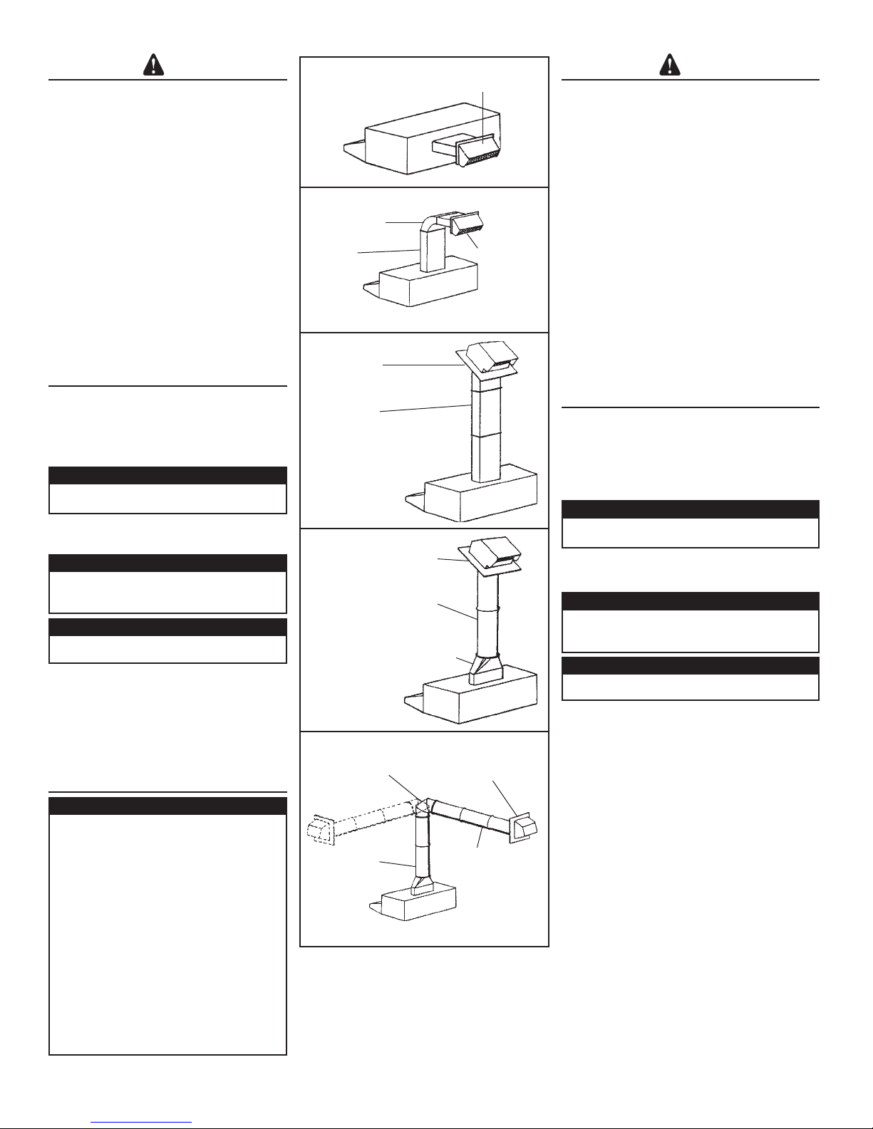
For Ducted Installations Only:
Begin planning ductwork by deciding where duct
will run between hood and outside. For best performance, use shortest possible duct run and a
minimum number of elbows. In more complex situations, 3-1/4” x 10” duct can be converted to round
duct by means of a transition. FIGS 1A - 1E show
several choices.
FIG. 1A: Ducting directly through outside wall. If
wall cap is used directly off back of hood, check to
make sure that damper flap in damper/duct connector on hood does not interfere with damper flap
in wall cap. If it does, remove flap on hood damper/
duct connector.
FIG. 1B: At times it will be easier to run duct vertically
and use an elbow.
FIG. 1C: Ducting straight up through roof using 3-1/4”
x 10” duct. For single story installations.
FIG. 1D: Straight up through roof using round duct.
FIG. 1E: Ducting between ceiling joists for multi-story
installations or through soffits above cabinets where
soffit connects to outside walls.
FIG. 1A
MODEL 639 OR 649 WALL CAP
TAPA PARA PARED MODELO 639 O 649
FIG. 1B
MODEL 429 ELBOW
CODO MODELO 429
MODEL 401
3-1/4" X 10" DUCT
MODELO 401
CONDUCTO
8,26 CM X
25,40 CM
(3-1/4 X 10 PULG.)
FIG. 1C
MODEL 634 OR 644
ROOF CAP
TAPA PARA TECHO
MODELO 634 O 644
MODEL 401
3-1/4" X 10" DUCT
MODELO 401
CONDUCTO 8,26 CM X 25,40 CM
(3-1/4 X 10 PULG.)
FIG. 1D
MODEL 634 OR 644 ROOF CAP
TAPA PARA TECHO MODELO 634 O 644
MODEL 406 6" ROUND DUCT
MODELO 406 CONDUCTO REDONDO DE
15,24 CM (6 PULG.)
MODEL 411 3–1/4" X 10" TO 6"
ROUND DUCT TRANSITION
MODELO 411
TRANSICIÓN A CONDUCTO REDONDO
DE 8,26 CM X 25,40 CM A 15,24 CM
(3-1/4 X 10 PULG. A 6 PULG.)
FIG. 1E
MODEL 419
ADJUSTABLE ELBOW
MODELO 419
CODO AJUSTABLE
MODEL 411
3–1/4" X 10" TO 6"
ROUND DUCT TRANSITION
MODELO 411
TRANSICION A
CONDUCTO
REDONDO DE
8,26 CM X 25,40 CM A 15,24 CM
(3-1/4 X 10 PULG. A 6 PULG.)
MODEL 641 WALL CAP
TAPA PARA PARED
MODELO 641
MODEL 639 OR
649 WALL CAP
TAPA PARA
PARED MODELO
639 O 649
MODEL 406
6" ROUND DUCT
MODELO 406
CONDUCTO REDONDO
15,24 CM (6 PULG.)
CUIDADO
1. Para el uso de interior solamente.
2. Para uso de ventilación general solamente. No lo
use para extraer materiales o vapores explosivos o
peligrosos.
3. Para evitar daño a los cojinetes del motor e impulsores
ruidosos y/o desequilibrados, mantenga la unidad de
potencia lejos de rocíos de yeso, polvo de construcción,
etc.
4. Este producto está equipado con un termostato que
puede activar el ventilador automáticamente. Para
reducir el riesgo de lesión, desconecte la potencia en
el panel de servicio y trábelo para evitar que ésta se
prenda automáticamente.
5. El motor de su capucha tiene una sobrecarga térmica
que apaga el motor automáticamente si éste se
sobrecalienta. El motor arranca de nuevo cuando se
enfría. Si el motor continúa apagándose y arrancando,
hay que hacerle servicio a la capucha.
6. Para atrapar impurezas de cocinado de la mejor
manera, la capucha de su estufa se debe montar
de 45,72 cm a 60,96 cm (18 - 24 pulg.) arriba de la
superficie de cocinado.
7. Por favor lea la etiqueta con especificaciones del
producto para más información y requisitos.
HERRAMIENTAS Y
MATE-
RIALES NECESARIOS
HERRAMIENTAS
q Taladro, eléctrico o de trinquete
q Gusanillo de taladro de hoja ancha de 3,18 cm
(1-1/4 pulg.)
q Destornilladores tipo phillips y tipo hoja
q Alicates
q Cinta para medir o regla y lápiz
Solamente para instalaciones con conductos:
q Sierra de hoja o sierra para yeso
q Tijeras para metal
MATERIALES
q Cableado eléctrico y artículos del tipo necesario para
cumplir con códigos locales
Solamente para instalaciones con conductos:
q Tapa para pared o techo
q Cemento para techo o masilla de calafateo
q Conductos y cinta de conductos
Solamente para instalaciones sin conductos:
q Un juego de dos paquetes de filtro 97007662 Mi-
Solamente para instalación en gabinetes de cocina con fondo
que no está a nivel con el marco:
q Dos tiras de madera de 2,54 cm X 5,08 cm X 30,48 cm
q Cuatro tornillos de cabeza plana de 3,18 cm (1-1/4 pulg.)
®
Sistema IV
crotek
(1 X 2 X 12 pulg. de tamaño aproximado que se pueden
conseguir localmente)
para madera para fijar las tiras al fondo del gabinete
2
PREPARE HOOD
1. Unpack hood and check contents. You should
receive:
1 - assembled hood
1 - plastic bag, containing:
4 - 7/8” wood screws for mounting hood to
cabinet
2 - 1/4” black sheet metal screws for mounting
damper/duct connector to hood
2 - aluminum filters
1 - damper/duct connector
For Ductfree Installations Only:
Discard damper/duct connector and two black sheet
metal screws.
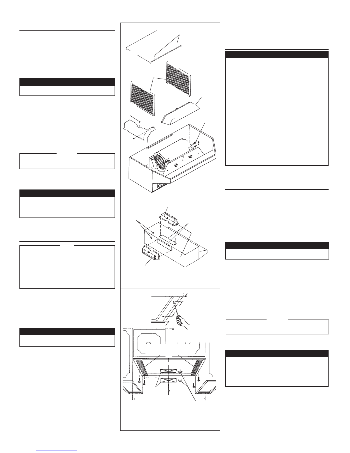
For Steps 2 - 6 below, refer to FIG. 2.
2. Set hood upside down and remove bottom cover
and screws.
3. Remove filters.
4. Remove wiring box cover and screws.
5. Remove blower assembly:
a.) Unplug blower.
b.) Loosen knurled nuts on mounting rods and slip
rods out of blower mounting brackets. Do not
remove nuts completely from rods.
c.) Lift out blower and set blower aside.
DO NOT GRASP BLOWER BY BLOWER WHEELS.
WHEELS MAY BE DAMAGED.
6. Remove light lens. Squeeze sides of lens toward
center of hood and lift lens out.
7. Remove either top or rear electrical knockout. (FIG.
3)
For Ducted Installations Only:
1. Remove either top or rear duct knockout. (FIG. 3)
2. Fasten damper/duct connector to hood over
opening. Use two black sheet metal screws
provided in parts bag. (FIG. 3)
CAUTION
PREPARE THE
INSTALLATION LOCATION
NOTE
IF DISTANCE BETWEEN WALL AND FRONT
OF CABINET FACE FRAME IS MORE THAN
12”, THERE WILL BE A GAP BETWEEN BACK
OF HOOD AND WALL. THIS IS NORMAL. TOP
FRONT EDGE OF HOOD SHOULD BE FLUSH
WITH FRONT OF CABINET FACE FRAME. OMIT
STEP 1 IF HOOD WILL BE INSTALLED UNDER
CABINETS WITH FLUSH BOTTOM.
1. For Cabinets With Recessed Bottoms ONLY: (FIG.
4)
Install wood filler strips on each side of recessed
area under cabinet. Use two 1” x 2” strips cut to
length (use thicker strips if necessary). Fasten
strips with wood screws about 3” in from each end.
2. Measure and mark the following: (FIG. 5)
a.) electrical wiring opening
For Ducted Installations Only:
b.) duct opening
3. Cut duct opening in wall or cabinet bottom.
4. Drill 1-1/4” electrical wiring opening in wall or
cabinet bottom.
5. Hold hood up against cabinet bottom and trace
keyhole slots onto cabinet bottom or filler strips. For
larger hoods: Two 1/4” dia. holes are provided for
secure mounting. They are located in top of hood
approx. 8” each side of center. Add filler strips for
these as necessary. Avoid blocking hood’s vertical
electrical knockout.
6. Screw four 7/8” wood screws from parts bag into
exact center of narrow end of keyhole slots marked
on cabinet bottom. Allow 3/8” of screws to project,
so hood can be fitted into place later.
7. Run electric wiring through hole drilled in wall or
cabinet. Provide 6” leads and install proper connector for type of wire used.
FIG. 2
STEP 2
PASO 2
STEP 3
PASO 3
STEP 6
PASO 6
STEP 4
PASO 4
FIG. 3
ELECTRICAL KNOCKOUTS
DISCOS REMOVIBLES
PARA LO ELECTRICO
HORIZONTAL DUCTING*
CONDUCTO HORIZONTAL*
* FOR DUCTED INSTALLATIONS ONLY.
* SOLAMENTE PARA INSTALACIONES CON CONDUCTOS.
VERTICAL DUCTING*
CONDUCTO VERTICAL*
DUCT KNOCKOUTS*
PIEZAS REMOVIBLES
DEL CONDUCTO*
STEP 5
PASO 5
HINGE PINS
PASADORES
DE GOZNE
FIG. 4
3"
7,62 CM (3 PULG.)
3"
7,62 CM (3 PULG.)
CUT STRIPS TO FIT
CORTE LAS TIRAS AL TAMAÑO
DESEADO
DUCT OPENINGS*
ABERTURAS DEL
CONDUCTO*
WIDTH OF RANGE HOOD
ANCHURA DE LA CAPUCHA
* FOR DUCTED INSTALLATIONS ONLY.
* SOLAMENTE PARA INSTALACIONES CON CONDUCTOS.
CENTER LINE
LINEA CENTRAL
PARA LA ESTUFA
ELECTRICAL
WIRING
OPENING
ABERTURA PARA
CABLEADO
ELECTRICO
3
PLANIFICANDO LA
INSTALACION DE
LOS CONDUCTOS
Solamente para instalaciones con conductos:
Comience la planificación de los conductos decidiendo
la ruta desde la capucha hasta el exterior. Para el mejor
desempeño, use la ruta más directa y el menor número
de codos. En situaciones más complejas, conductos
de 8,26 cm X 25,40 cm (3-1/4 X 10 pulg.) se pueden
convertir a conductos redondos usando un adaptador.
Las Figs. 1A - 1E le muestran varias opciones.
FIG. 1A: conductos directamente a través de la pared
exterior. Si se usa una tapa de pared desde la parte
trasera de la capucha, verifique que la aleta del amortiguador en la unión del amortiguador/conducto en la
capucha no interfiera con la aleta del amortiguador en
la tapa para pared. Si interfiere, quite la aleta en la unión
amortiguador/conducto de la capucha.
FIG. 1B: a veces es mejor usar conducto vertical y usar
un codo.
FIG. 1C: conductos verticales a través del techo con
conductos de 8,26 cm X 25,40 cm (3-1/4 X 10 pulg.).
Para instalaciones de un piso.
FIG.1D: vertical hasta el techo con un conducto redondo.
FIG. 1E: conductos entre las vigas del cielo raso para
instalaciones de varios pisos o a través de sófitos arriba de gabinetes donde los sófitos llegan a las paredes
exteriores.
PREPARANDO
LA CAPUCHA
1. Saque la capucha y verifique su contenido. Usted debe
tener:
1 - capucha armada
1 - bolsa plástica que contiene:
4 - tornillos para madera de 2,22 cm (7/8 pulg.) para
montar la capucha al gabinete
2 - tornillos negros de 0,64 cm (1/4 pulg.) para lámina
de metal para montar la unión del amortiguador/
conducto a la capucha
2 - filtros de aluminio
1 - unión del amortiguador/conducto
Solamente para instalaciones sin conductos:
Deseche la unión del amortiguador/conducto y los dos
tornillos negros para lámina de metal.
Para pasos 2 - 6 abajo, referirse a FIG. 2.
2. Coloque la capucha cabeza abajo y quite la tapa inferior
y los tornillos.
3. Saque los filtros.
4. Saque la tapa de la caja de conexiones y los tornillos.
5. Saque el conjunto del soplador:
a.) Desenchufe el soplador.
b.) Afloje las tuercas nudosas de las varas
de montaje y deslice éstas del soporte de
montaje del soplador. No saque las tuercas
completamente de las varas.
c.) Alce el soplador y póngalo a un lado.
NO ALCE EL SOPLADOR POR SUS RUEDAS. ESTAS
SE PUEDEN DAÑAR.
6. Saque el lente de luz. Apriete los lados del lente hacia
el centro de la capucha y sáquelo.
7. Saque el disco removible superior o el trasero. (FIG. 3)
Solamente para instalaciones con conductos:
1. Saque el disco removible de la parte superior, o el
trasero. (FIG. 3)
2. Fije la unión del amortiguador/conducto a la
capucha sobre la abertura. Use dos tornillos negros
para lámina de metal que se suministran en la bolsa
de piezas. (FIG. 3)
CUIDADO
 Loading...