

Page 1
MODEL 791LED
ADDITIONAL
JOIST
!
VENTILATION FAN
WITH LED LIGHT
READ AND SAVE THESE INSTRUCTIONS
Page 1
WARNING
TO REDUCE THE RISK OF FIRE, ELECTRIC SHOCK, OR
INJURY TO PERSONS, OBSERVE THE FOLLOWING:
1. Use this unit only in the manner intended by the manufacturer.
If you have questions, contact the manufacturer at the
address or telephone number listed in the warranty.
2. Before servicing or cleaning unit, switch power off at service
panel and lock the service disconnecting means to prevent
power from being switched on accidentally. When the service
disconnecting means cannot be locked, securely fasten a
prominent warning device, such as a tag, to the service panel.
3. Installation work and electrical wiring must be done by a
qualified person(s) in accordance with all applicable codes
and standards, including fire-rated construction codes and
standards.
4. Sufficient air is needed for proper combustion and exhausting
of gases through the flue (chimney) of fuel burning equipment
to prevent backdrafting. Follow the heating equipment
manufacturer’s guideline and safety standards such as those
published by the National Fire Protection Association (NFPA),
and the American Society for Heating, Refrigeration and
Air Conditioning Engineers (ASHRAE), and the local code
authorities.
5. When cutting or drilling into wall or ceiling, do not damage
electrical wiring and other hidden utilities.
6. Ducted fans must always be vented to the outdoors.
7. Acceptable for use over a tub or shower when connected to
a GFCI (Ground Fault Circuit Interrupter) - protected branch
circuit.
8. Not for use in kitchens.
9. This unit must be grounded.
10. This unit is U.L. listed. Type I.C. inherently protected.
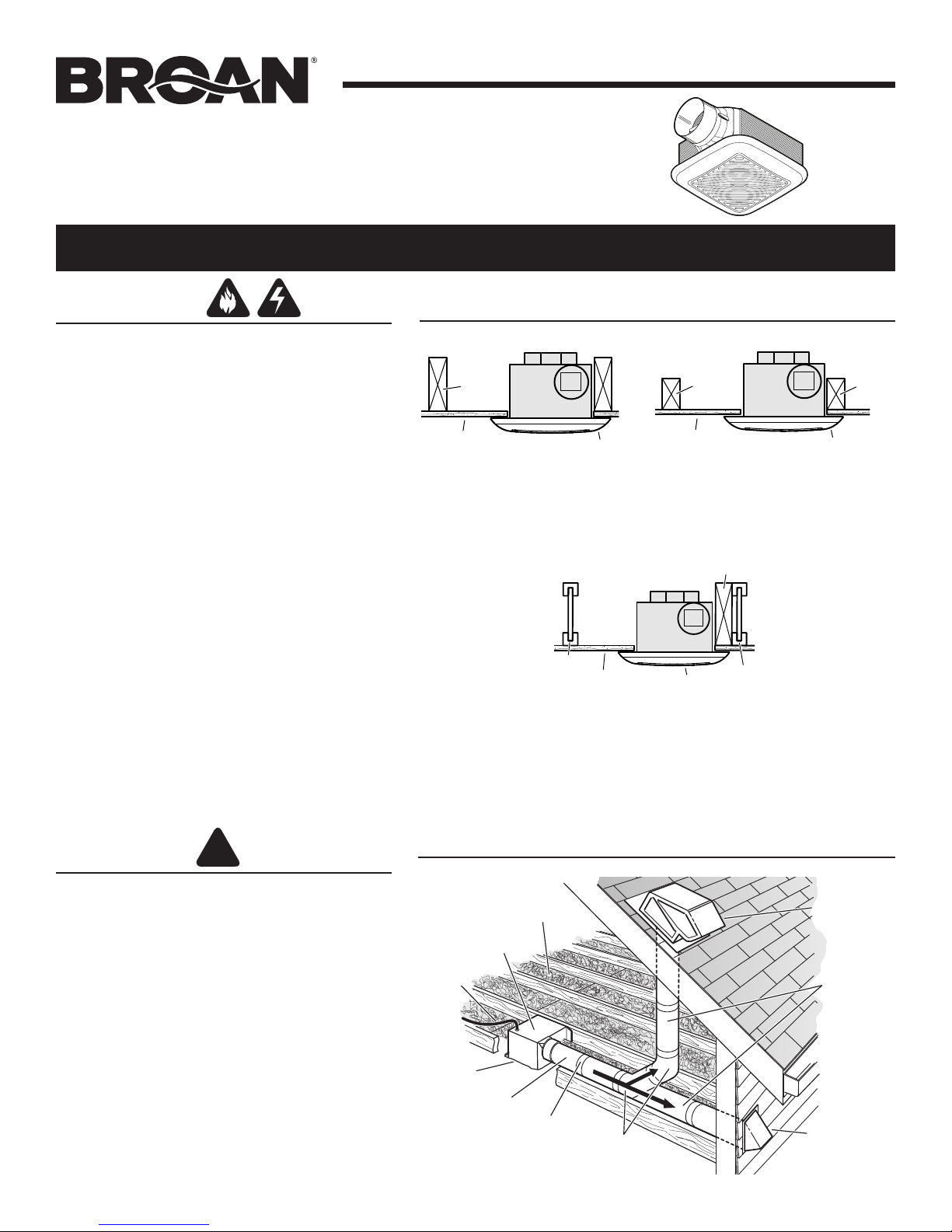
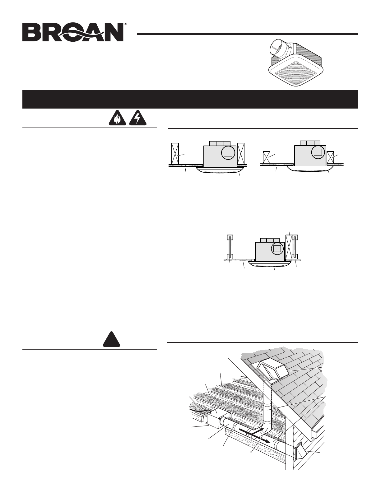
TYPICAL INSTALLATIONS
2 x 4
CEILING
JOIST
CEILING
MATERIAL
HOUSING
HOUSING
GRILLE
HOUSING MOUNTED
DIRECTLY TO JOIST
2x6 (or larger)
Discharge parallel to joists.
"I"
JOIST
CEILING
MATERIAL
HOUSING MOUNTED TO “I” JOIST
Requires additional framing
for mounting.
Discharge parallel to joists.
Additional framing must be a 2x6 (minimum height).
*
CEILING
JOIST or
TRUSS
CEILING
MATERIAL
HOUSING MOUNTED
TO 2x4 TRUSS
Discharge parallel to joists.
FRAMING
HOUSING
HOUSING
GRILLE
"I"
HOUSING
HOUSING
*
GRILLE
2 x 4
CEILING
JOIST or
TRUSS
CAUTION
1. For general ventilating use only. Do not use to exhaust
hazardous or explosive materials and vapors.
2. This product is designed for installation in FLAT CEILINGS
ONLY. Do not mount this product in a wall.
3. The light fixture assembly must be mounted to the fan
housing assembly included with this product. Do not mount
the light fixture assembly to a wiring outlet box.
4. To avoid motor bearing damage and noisy and/or
unbalanced impellers, keep drywall spray, construction
dust, etc. off power unit.
5. Please read specification label on product for further
information and requirements.
Installer: Leave this manual with the
homeowner.
Homeowner: Use and Care
information on page 4.
PLAN THE INSTALLATION
INSULATION
(Place around and
over fan housing.)
FAN
HOUSING
POWER
CABLE*
Seal gaps
around
housing.
4-IN. ROUND
DUCT*
*Purchase
separately.
Seal duct
joints with
tape.
4-IN. ROUND
OR
ELBOWS*
ROOF CAP*
(with built-in
damper)
Keep duct
runs short.
WALL CAP*
(with built-in
damper)
Page 2
MODEL 791LED
Page 2
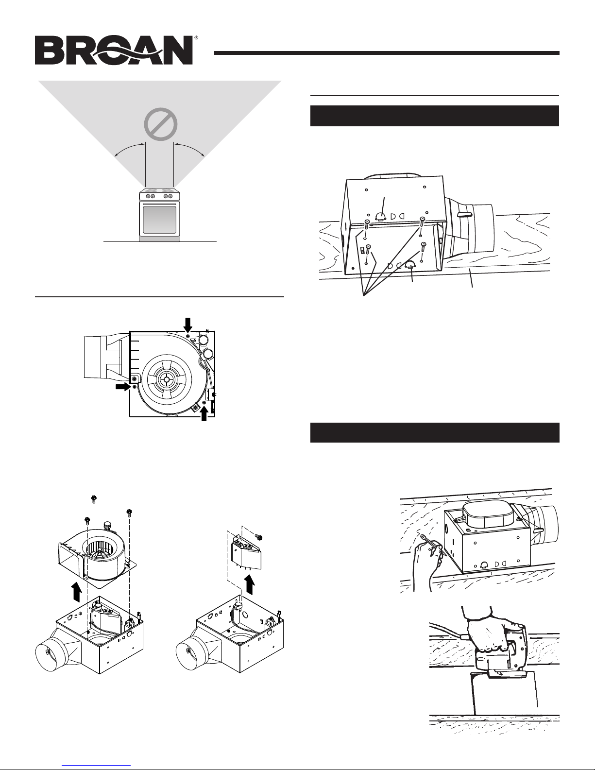
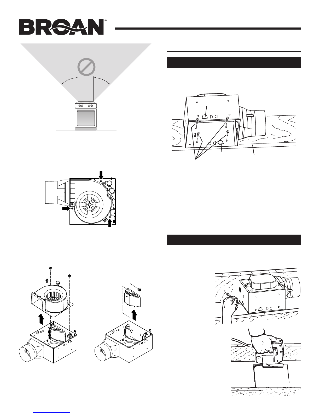
NOT FOR USE IN A COOKING AREA
Do not install above or inside this area
45° 45°
Cooking
Equipment
Floor
PREPARE THE HOUSING
INSTALL THE HOUSING
New Construction
1. Choose the location for your fan/light in the ceiling. For
best possible performance, use the shortest possible duct
run and a minimum number of elbows.
TAB
TAB
MOUNTING SCREWS
2. Position fan housing against joist so that bottom
edge of housing will be flush with finished ceiling.
Additional positioning feature for 1/2” thick
ceiling material:
Bend tab, on either side of housing,
housing until tab contacts bottom edge of joist.
3. Use (4) mounting screws (included) to attach housing
to joist.
BOTTOM EDGE OF JOIST
900 outward. Lift
1. Unplug blower and remove (3) screws securing blower
assembly to housing.
2. Remove blower
assembly from
housing and set
blower assembly
aside.
3. Unplug light wires
from white receptacle.
Remove wiring plate
from housing and set
plate aside.
Existing Construction
1. Choose the location for your fan/light in the ceiling. For
best possible performance, use the shortest possible duct
run and a minimum number of elbows.
2. In attic,
position fan
housing
against joist.
Trace outline
of housing
on ceiling
material.
3. Set housing aside
and cut ceiling
opening slightly
larger than marked.
Page 3
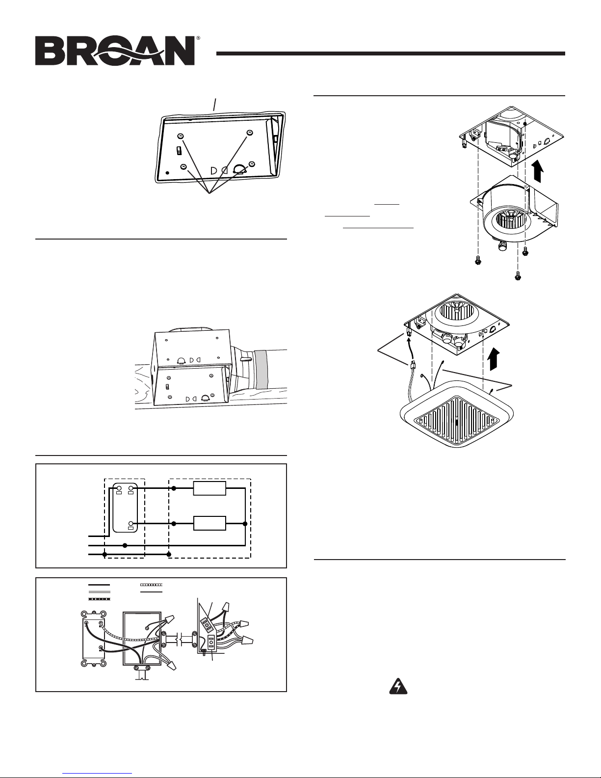
UNIT
SWITCH BOX
LINE
4. Place housing in
MATERIAL & HOUSING
opening so that
its bottom edge is
flush with finished
ceiling. Screw
housing to joist
through holes in
housing as shown.
5. Seal between
ceiling material and
SEAL BETWEEN CEILING
housing to prevent
air leakage.
MOUNTING SCREWS
INSTALL THE DUCTWORK
NOTE: The duct connector has a counter-balanced damper
flap. The flap will be “open” approx. 1” when duct connector
is attached to housing. This design permits insulation to be
in direct contact with fan/light housing per UL (Underwriters
Laboratories) standards. The slightest backdraft, however,
will close the damper flap, preventing air from entering unit
or finished space.
MODEL 791LED
Page 3
FINISH THE INSTALLATION
1. Re-install blower
assembly removed in
Step 1 under “PREPARE
THE HOUSING”. Plug
blower into black
receptacle and light plug
into white receptacle.
1. Connect 4” round
duct to damper/
duct connector
and extend duct
to outside through
a roof or wall cap.
Check damper to
make sure that it
opens freely. Tape
all duct connections to make them secure and air tight.
CONNECT THE WIRING
SCHEMATIC WIRING DIAGRAM
LIGHT
SWITCH
VENT
SWITCH
BLK
WHT
IN
GRD
LIGHT
FAN
DUAL CONTROL
(purchase separately)
BLACK
WHITE
BLUE
SWITCH BOX
120 VAC LINE IN
RED
BLK
WHT
GRD
BLU
BLK
RED
GROUND
(bare)
LIGHT
(WHITE)
(BLACK)
RECEPTACLE
RECEPTACLE
1. Wire unit as shown. Re-install wiring plate removed in
Step 2 under “PREPARE THE HOUSING”.
2. Run electrical cable as direct as possible to unit. Do not
allow cable to touch sides or top of unit after installation
is complete.
VENT
BLACK
(FAN)
WHITE
(LIGHT)
WHT
WHT
LED WIRE
CONNECTORS
GRILLE
SPRINGS
2. Locate grille over fan housing. Squeeze grille springs
together and insert springs into slots in sides of
housing.
3. Connect LED wire connectors together.
4. Push grille up against ceiling.
USE AND CARE
Operation
To Operate Fan and Light
Use only an ON/OFF or timer switch to operate the fan.
Use only an ON/OFF switch, timer switch or relay-switch
to operate the LED light.
The LED light cannot be used with a dimmable switch.
Both the fan and LED light can be put on one switch.
WARNING Before servicing or cleaning unit,
switch power off at service panel and lock the service
disconnecting means to prevent power from being
switched on accidentally. When the service disconnecting
means cannot be locked, securely fasten a prominent
warning device, such as a tag, to the service panel.
Page 4
Cleaning and Maintenance
To Clean
For quiet and efficient operation, long life and attractive
appearance: Remove and unplug grille assembly. Vacuum grille
and interior of unit with a dusting brush attachment.
The motor is permanently lubricated and never needs oiling. If
the motor bearings are making excessive or unusual noises,
replace the motor.
Troubleshooting
Symptom: The fan does not run.
• Check for an open fuse or circuit breaker in the building’s
service panel.
MODEL 791LED
Page 4
• Check that the plug-in connection for the motor and the LED
light assembly are seated firmly in place.
• Check that the blower wheel spins freely.
Symptom: The fan runs erratically.
• Check that the blower wheel is firmly attached to the motor
shaft and both spin freely.
Symptom: The fan seems noisy.
• Check that the back draft damper in the fan’s duct connector
pivots freely. Screws used to attach the ducting to the duct
connector may be preventing the damper from opening.
• Check that the back draft damper in the wall or roof cap pivots
freely. These dampers are sometimes mistakenly painted shut
or obstructed by bird and insect debris.
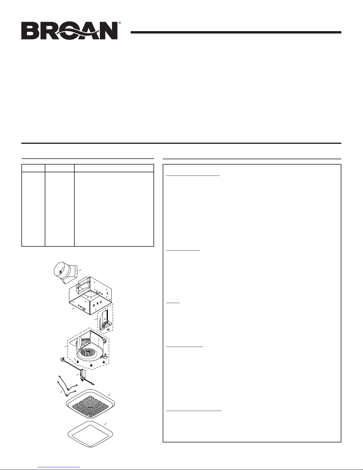
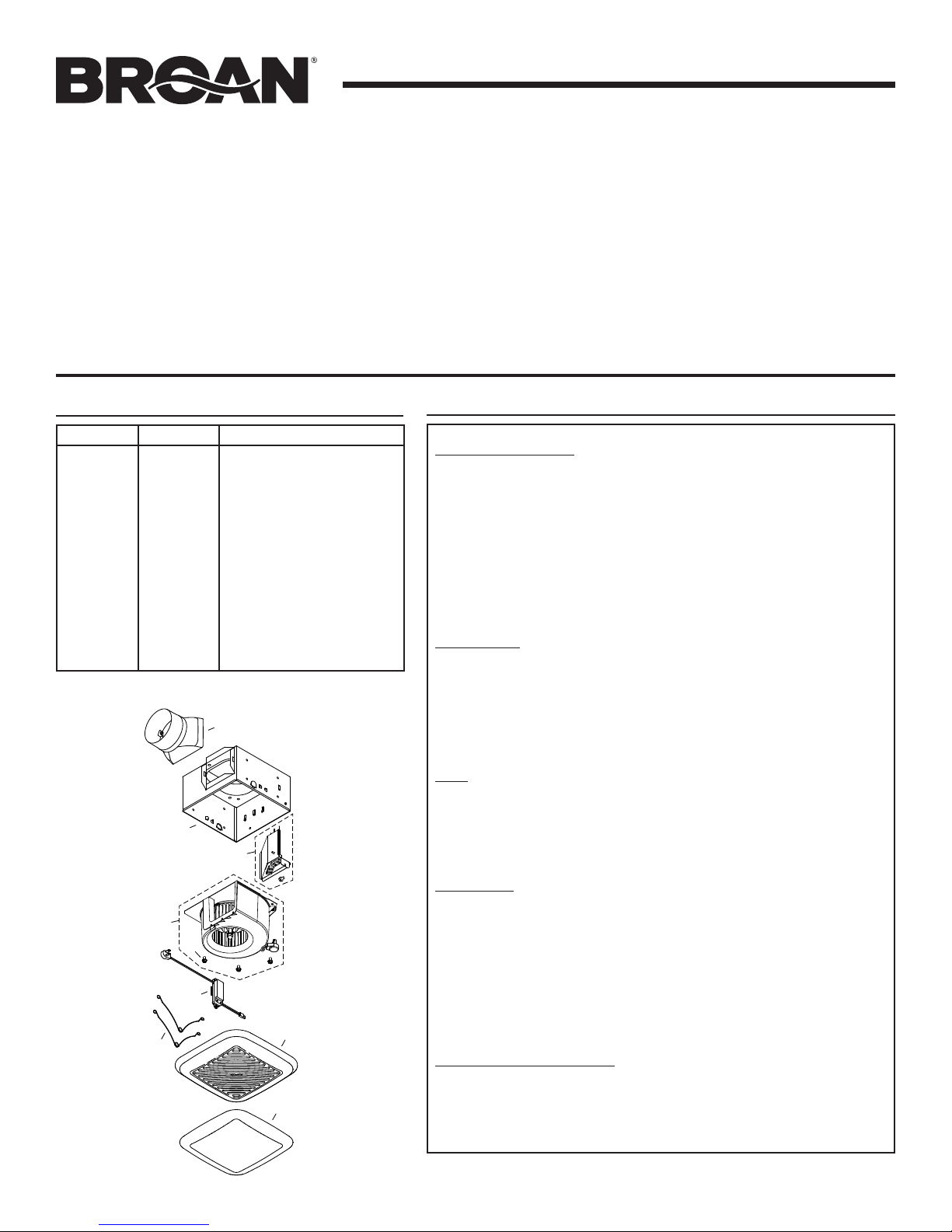
SERVICE PARTS
KEY NO. PART NO. DESCRIPTION
1 97019447 Grille Assembly
(includes Key Nos. 2 & 3)
2 99111575 Lens
3 99140199 Grille Springs (2 req.)
4 99271496 LED Driver Assembly
5 9701874 9 Blower Assembly
(includes Key No. 6 - 3 req.)
6 99160441 Screw, Motor #8-32 x .275 (3 req.)
7 97018750 Wire Panel Assembly
8 97018804 Damper / Duct Connector
9 97019355 Housing Assembly
Order replacement parts by “PART NO.” - not by “KEY NO.”
8
9
7
5
6
4
3
1
2
WARRANTY
Warranty Period and Exclusions: Broan-NuTone LLC (the “Company”) warrants to the original consumer
purchaser of its product (“you”) that the product (the “Product”) will be free from material defects in the
Product or its workmanship for a period of one (1) year from the date of original purchase. The warranty on
the light bulbs provided with the Product is one (1) year and does not cover lamp/bulb breakage.
The limited warranty period for any replacement parts provided by the Company and for any Products
repaired or replaced under this limited warranty shall be the remainder of the original warranty period.
This warranty does not cover speed controls, fluorescent lamp starters, tubes, halogen and incandescent
bulbs, fuses, filters, ducts, roof caps, wall caps and other accessories for ducting that may be purchased
separately and installed with the Product. This warranty also does not cover (a)normal maintenance and
service, (b)normal wear and tear, (c)any Products or parts which have been subject to misuse, abuse,
abnormal usage, negligence, accident, improper or insufficient maintenance, storage or repair (other
than repair by the Company), (d) damage caused by faulty installation, or installation or use contrary
to recommendations or instructions, (e) any Product that has been moved from its original point of
installation, (f)damage caused by environmental or natural elements, (g) damage in transit, (h)natural
wear of finish, (i)Products in commercial or nonresidential use, or (j) damage caused by fire, flood or
other act of God. This warranty covers only Products sold to original consumers in the United States by
the Company or U.S. distributors authorized by the Company.
This warranty supersedes all prior warranties and is not transferable from the original consumer purchaser.
No Other Warranties: This Limited Warranty contains the Company’s sole obligation and your sole remedy
for defective products. The foregoing warranties are exclusive and in lieu of any other warranties, express
or implied. THE COMPANY DISCLAIMS AND EXCLUDES ALL OTHER EXPRESS WARRANTIES, AND
DISCLAIMS AND EXCLUDES ALL WARRANTIES IMPLIED BY LAW, INCLUDING WITHOUT LIMITATION
THOSE OF MERCHANTABILITY AND FITNESS FOR A PARTICULAR PURPOSE. To the extent that applicable
law prohibits the exclusion of implied warranties, the duration of any applicable implied warranty is limited
to the period specified for the express warranty above. Some states do not allow limitations on how long
an implied warranty lasts, so the above limitation may not apply to you. Any oral or written description
of the Product is for the sole purpose of identifying it and shall not be construed as an express warranty.
Whenever possible, each provision of this Limited Warranty shall be interpreted in such manner as to
be effective and valid under applicable law, but if any provision is held to be prohibited or invalid, such
provision shall be ineffective only to the extent of such prohibition or invalidity, without invalidating the
remainder of such provision or the other remaining provisions of the Limited Warranty.
Remedy: During the applicable limited warranty period, the Company will, at its option, provide replacement
parts for, or repair or replace, without charge, any Product or part thereof, to the extent the Company finds
it to be covered by and in breach of this limited warranty under normal use and service. The Company
will ship the repaired or replaced Product or replacement parts to you at no charge. You are responsible
for all costs for removal, reinstallation and shipping, insurance or other freight charges incurred in the
shipment of the Product or part to the Company. If you must send the Product or part to the Company, as
instructed by the Company, you must properly pack the Product or part—the Company is not responsible
for damage in transit. The Company reserves the right to utilize reconditioned, refurbished, repaired or
remanufactured Products or parts in the warranty repair or replacement process. Such Products and parts
will be comparable in function and performance to an original Product or part and warranted for the
remainder of the original warranty period.
Exclusion of Damages: THE COMPANY’S OBLIGATION TO PROVIDE REPLACEMENT PARTS, OR REPAIR
OR REPLACE, AT THE COMPANY’S OPTION, SHALL BE YOUR SOLE AND EXCLUSIVE REMEDY UNDER
THIS LIMITED WARRANTY AND THE COMPANY’S SOLE AND EXCLUSIVE OBLIGATION. THE COMPANY
SHALL NOT BE LIABLE FOR INCIDENTAL, INDIRECT, CONSEQUENTIAL OR SPECIAL DAMAGES ARISING
OUT OF OR IN CONNECTION WITH THE PRODUCT, ITS USE OR PERFORMANCE.
Some states do not allow the exclusion or limitation of incidental or consequential damages, so the above
limitation or exclusion may not apply to you. This warranty gives you specific legal rights, and you may
also have other rights, which vary from state to state.
This warranty covers only replacement or repair of defective Products or parts thereof at the Company’s
main facility and does not include the cost of field service travel and living expenses.
Any assistance the Company provides to or procures for you outside the terms, limitations or exclusions
of this limited warranty will not constitute a waiver of such terms, limitations or exclusions, nor will such
assistance extend or revive the warranty.
The Company will not reimburse you for any expenses incurred by you in repairing or replacing any
defective Product, except for those incurred with the Company’s prior written permission.
How to Obtain Warranty Service: To qualify for warranty service, you must (a)notify the Company at
the address or telephone number stated below within seven (7)days of discovering the covered defect,
(b)give the model number and part identification and (c)describe the nature of any defect in the Product or
part. At the time of requesting warranty service, you must present evidence of the original purchase date.
If you cannot provide a copy of the original written limited warranty, then the terms of the Company’s most
current written limited warranty for your particular product will control.The most current limited written
warranties for the Company’s products can be found at www.broan.com .
Broan-NuTone LLC 926 West State Street, Hartford, WI 53027 www.broan.com 800-637-1453
Limited Warranty
99045211B
Page 5
MODELO 791LED
ESTRUCTURA
VIGUETA
!
Página 5
VENTILADOR
CON LUZ LED
LEA Y CONSERVE ESTAS INSTRUCCIONES
ADVERTENCIA
PARA REDUCIR EL RIESGO DE INCENDIOS, DESCARGAS
ELÉCTRICAS O LESIONES PERSONALES, SIGA LAS SIGUIENTES
PRECAUCIONES:
1. Use la unidad solo de la manera indicada por el fabricante. Si tiene
preguntas, comuníquese con el fabricante a la dirección o al número
telefónico que se incluye en la garantía.
2. Antes de dar servicio a la unidad o de limpiarla, interrumpa el
suministro eléctrico en el panel de serv icio y bloquee los medios de
desconexión del servicio para evitar que la electricidad se reanude
accidentalmente. Cuando no sea posible bloquear los medios de
desconexión del servicio, fije firmemente una señal de advertencia
(como una etiqueta) en un lugar visible del panel de servicio.
3. El trabajo de instalación y el cableado eléctrico deben estar a cargo
de personal capacitado, de acuerdo con todos los códigos y normas
correspondientes, incluidos los códigos y normas de construcción
específicos sobre protección contra incendios.
4. Es necesario suficiente aire para que se lleve a cabo una combustión
y una extracción adecuadas de los gases a través del tubo de
humos (chimenea) del equipo quemador de combustible, con el fin
de evitar el contratiro. Siga las directrices y las normas de seguridad
del fabricante del equipo de calefacción, como las publicadas por
la Asociación Nacional de Protección contra Incendios (National
Fire Protection Association, NFPA), la Sociedad Americana de
Ingenieros de Calefacción, Refrigeración y Aire Acondicionado
(American Society for Heating, Refrigeration and Air Conditioning
Engineers, ASHRAE) y las autoridades normativas locales.
5. Al cortar o perforar a través de la pared o del cielo raso, tenga
cuidado de no dañar el cableado eléctrico ni otros servicios ocultos.
6. Los ventiladores con conductos siempre deben ventearse hacia
el exterior.
7. Esta unidad puede instalarse sobre una tina o ducha siempre que se
conecte a un GFCI (interruptor accionado por pérdida de conexión
a tierra) en un circuito de derivación protegido.
8. Esta unidad no está diseñada para utilizarse en cocinas.
9. Esta unidad debe estar conectada a tierra.
10. Esta unidad está aprobada por U.L. y tiene protección inherente
del tipo I.C.
INSTALACIONES TÍPICAS
VIGUETA o VIGA
VIGUETA DE
CIELO RASO
HOUSING
CUBIERTA
MATERIAL DEL
CIELO RASO
REJILLA
CUBIERTA MONTADA
DIRECTAMENTE EN LA VIGUETA
2 X 6 (o más grande)
Descarga paralela a las viguetas.
VIGUETA
“
I
”
MATERIAL DEL
CIELO RASO
CUBIERTA MONTADA EN UNA VIGUETA “I”
Se requiere una estructura adicional
Descarga paralela a las viguetas.
La estructura adicional debe ser 2 x 6 (altura mínima).
*
DE 2 x 4 DE
CIELO RASO
MATERIAL DEL
CIELO RASO
CUBIERTA MONTADA
DIRECTAMENTE EN LA
VIGUETA2 X 6
Descarga paralela a las viguetas.
ADICIONAL
HOUSING
CUBIERTA
“
I
REJILLA
”
para el montaje.
HOUSING
CUBIERTA
*
VIGUETA o VIGA
REJILLA
DE 2 x 4 DE
CIELO RASO
PRECAUCIÓN
1. Solo para usarse como medio de ventilación general. No debe
usarse para la extracción de materiales o vapores peligrosos o
explosivos.
2. Este producto está diseñado para instalarse SOLAMENTE EN UN
CIELO RASO PLANO. No monte este producto en una pared.
3. El conjunto del accesorio de la lámpara debe montarse en el
conjunto de la cubierta del ventilador que se incluye con este
producto. No monte el conjunto del accesorio de la lámpara en
una caja de tomacorriente de cableado.
4. Para evitar daños a los cojinetes del motor y rotores ruidosos o
desbalanceados, mantenga la unidad de potencia protegida contra
rociados de yeso, polvos de construcción, etc.
5. Lea la etiqueta de especificaciones del producto para ver
información y requisitos adicionales.
Aviso al instalador: Deje este manual con el
dueño de la casa.
Aviso al dueño de la casa: Las instrucciones
de operación y limpieza se encuentran en la
página 8.
PLANEACIÓN DE LA INSTALACIÓN
AISLAMIENTO
(Coloque alrededor
CABLE
ELÉCTRICO*
Selle las
separaciones
alrededor de
la cubierta.
CONDUCTO
REDONDO DE
4 PULG. (10 CM)*
*Se compra
por separado.
y sobre la cubierta
del ventilador)
CUBIERTA DEL
VENTILADOR
Selle con cinta
las uniones de
los conductos.
O
CODOS
REDONDOS
DE 4 PULG. (10 CM)*
TAPA DE TECHO*
(con regulador
de tiro integrado)
Mantenga cortos
los tramos
de conductos.
TAPA DE PARED*
(con regulador
de tiro integrado)
Page 6
MODELO 791LED
Página 6
NO USAR EL PRODUCTO EN UN ÁREA DE COCINA
No instale el equipo sobre o dentro de esta área
45° 45°
Equipo
de cocina
Piso
PREPARACIÓN DE LA CUBIERTA
INSTALACIÓN DE LA CUBIERTA
Nueva construcción
1. Seleccione la ubicación del ventilador con lámpara en el cielo
raso. Para obtener el mejor desempeño posible, utilice el tramo
de conducto más corto posible y el menor número de codos.
LENGÜETA
LENGÜETA
TORNILLOS DE MONTAJE
2. Coloque la cubierta del ventilador contra la vigueta, de manera
que el borde inferior de la cubierta quede al ras del cielo raso
terminado.
Característica adicional para la colocación
enmaterial de cielo raso de ½ pulg. (1.3 cm):
Doble a 90o y hacia afuera la lengüeta de cualquiera
de los lados de la cubierta. Levante la cubierta hasta
que la lengüeta entre en contacto con el borde inferior
de la vigueta.
3. Use cuatro (4) tornillos de montaje (incluidos) para fijar la
cubierta a la vigueta.
BORDE INFERIOR DE
LA VIGUETA
1. Desconecte el ventilador y retire los tres (3) tornillos
que aseguran el conjunto del ventilador a la cubierta.
2. Retire el conjunto
del ventilador
de la cubierta y
déjelo a un lado.
3. Desenchufe los cables
de la luz del receptáculo
blanco. Retire la placa de
cableado de la cubierta
y déjela a un lado.
Construcción existente
1. Seleccione la ubicación del ventilador con lámpara en el cielo
raso. Para obtener el mejor desempeño posible, utilice el tramo
de conducto más corto posible y el menor número de codos.
2. En el ático,
coloque la
cubierta del
ventilador
contra la viga.
Haga un trazo
del perímetro
de la cubierta
en el material
del cielo raso.
3. Deje la cubierta a un
lado y corte la abertura
del cielo raso un poquito
mayor que la trazada.
Page 7

MODELO 791LED
INTERRUPTOR
4. Coloque la cubierta en la
APLIQUE SELLADOR ENTRE EL MATERIAL
DEL CIELO RASOY LA CUBIERTA
abertura de manera que su
borde inferior quede al ras del
cielo raso terminado. Atornille
la cubierta en la vigueta a
través de los orificios de la
cubierta, como semuestra.
5. Aplique sellador entre el
material del cielo raso y la
cubierta para evitar lafuga
deaire.
TORNILLOS DE MONTAJE
INSTALACIÓN DEL SISTEMA
DE CONDUCTOS
NOTA: El conector del conducto tiene una aleta compensadora para
el regulador de tiro. Cuando el conector esté conectado en la cubierta,
la aleta estará “abierta” aproximadamente 1 pulg. (2.5 cm). Este diseño
permite que el material de aislamiento esté en contacto directo con la
cubierta del ventilador con lámpara de acuerdo con las normas de UL
(Underwriters Laboratories). Sin embargo, la más ligera corriente invertida
cerrará la aleta del regulador de tiro, evitando así la entrada de aire a la
unidad o al espacio terminado.
1. Conecte el conducto
redondo de 4 pulg.
(10cm) en el conectador
del regulador de tiro/
conducto y extienda
el conducto hasta
el exterior a través
de una tapa de
techo o de pared.
Revise el regulador de tiro para asegurarse de que abra libremente.
Coloquecinta en todas las conexiones de los conductos para
asegurarlas y hacerlas herméticas.
CONECTE EL CABLEADO
DIAGRAMA ELÉCTRICO
LÁMPARA
(NEGRO)
UNIDAD
RECEPTÁCULO
NEGRO
(VENTILADOR)
BLANCO
(LÁMPARA)
BLANCO
BLANCO
AZUL
INTERRUPTOR
D E L A
LÁMPARA
INTERRUPTOR
DEL VENTILADOR
NEGRO
LÍNEA DE
BLANCO
ENTRADA
TIERRA
LÁMPARA
VENTILADOR
CONTROL DOBLE
(se compra por separado)
CAJA DEL
NEGRO
BLANCO
AZUL
CAJA DEL INTERRUPTOR
LÍNEA DE ENTRADA DE 120 VCA
ROJO
NEGRO
BLANCO
TIERRA
ROJO
TIERRA
(desnudo)
NEGRO
(BLANCO)
VENTILADOR
RECEPTÁCULO
1. Conecte la unidad como se muestra. Vuelva a colocar la placa
de cableado que retiró en el Paso 2 bajo “PREPARACIÓN DE LA
CUBIERTA”.
2. Extienda el cable eléctrico a la unidad tan directamente como sea
posible. No permita que el cable toque los costados ni la parte superior
de la unidad después de que la instalación esté terminada.
Página 7
FINALIZACIÓN DE LA INSTALACIÓN
1. Vuelva a colocar el
conjunto del ventilador
que retiró en el Paso 1
bajo “PREPARACIÓN DE
LACUBIERTA”. Conecte el
ventilador en el receptáculo
negro y el enchufe de la luz
en el receptáculo blanco.
CONECTORES
DEL CABLE
DELLED
MUELLES
DE LA
REJILLA
2. Localice la rejilla sobre la cubierta del ventilador. Comprima
entre sí los resortes de la rejilla e introdúzcalos en las
ranuras a los lados de la cubierta.
3. Conecte juntos los conectores de los cables del LED.
4. Empuje la rejilla contra el cielo raso.
USO Y CUIDADO
Funcionamiento
Para hacer funcionar el ventilador y la luz
Use solamente un interruptor de ENCENDIDO/APAGADO o un
temporizador para hacer funcionar el ventilador.
Use solamente un interruptor de ENCENDIDO/APAGADO, un
temporizador o un relé-interruptor para hacer funcionar la luz LED.
La luz LED no se puede usar con un interruptor atenuable.
Tanto el ventilador como la luz LED se pueden colocar enun
interruptor.
ADVERTENCIA Antes de dar servicio
a la unidad o de limpiarla, interrumpa el suministro
eléctrico en el panel de servicio y bloquee los medios
dedesconexión del servicio para evitar que la
electricidad se reanude accidentalmente. Cuando no sea
posible bloquear los medios de desconexión del servicio,
fije firmemente una señal de advertencia (como una
etiqueta) en un lugar visible del panel de servicio.
Page 8
Limpieza y mantenimiento
Para limpiarlo
Para obtener un funcionamiento silencioso y eficiente, una
larga vida y una apariencia atractiva: Retire y desconecte el
conjunto de la rejilla. Aspire la rejilla y el interior de la unidad
con un aditamento de cepillo para sacudir.
El motor está permanentemente lubricado y nunca necesitará
ponerle aceite. Si los cojinetes del motor hacen ruidos
inusuales o excesivos, reemplace el motor.
Resolución de problemas
Síntoma: El ventilador no funciona.
• Compruebe si hay un fusible o un interruptor automático
abierto en el panel de servicio del edificio.
MODELO 791LED
Página 8
• Compruebe que el conector enchufable para el motor y el
conjunto de la luz LED estén firmemente asentados en su lugar.
• Compruebe que la rueda del ventilador gire sin obstrucciones.
Síntoma: El ventilador funciona de forma errática.
• Compruebe que la rueda del ventilador esté firmemente
acoplada al eje del motor y que ambos giren sin obstrucciones.
Síntoma: El ventilador hace demasiado ruido.
• Compruebe que el regulador de tiro invertido del conector de
conductos del ventilador gire sin obstrucciones. Los tornillos
utilizados para afianzar el conducto al conector de conductos
pueden impedir que el regulador de tiro se abra.
• Compruebe que el regulador de tiro invertido del conector de
conductos de la tapa de techo o de pared gire sin obstrucciones.
Estos reguladores suelen cerrarse accidentalmente después de
ser pintados o suelen obstruirse con pájaros o restos de insectos.
PIEZAS DE SERVICIO
N.º DE CLAVE N.º DE PIEZA DESCRIPCIÓN
1 97019447 Conjunto de la rejilla
2 99111575 Lente
3 99140199 Resortes de la rejilla
4 99271496 Conjunto impulsor de LED
5 97018749 Conjunto del ventilador
6 99160441 Tornillo, motor
7 97018750 Conjunto del panel de cableado
8 97018804 Conector del regulador
9 97019355 Conjunto de la cubierta
Pida piezas de repuesto dando como referencia el
o
N.
DE PIEZA, no el N.o DE CLAVE.
9
5
6
4
3
(incluye claves N.o 2 y 3)
(se requieren 2)
(incluye clave N.
o
8-32 x 0.275 pulg. (req. 3)
N.
de tiro/conducto
8
7
1
2
o
6; req. 3)
GARANTÍA
Periodo y exclusiones de la garantía: Broan-NuTone LLC (la “Compañía”) garantiza al consumidor comprador original de su
producto (“usted”) que el producto (el “Producto”) estará libre de defectos en materiales en el Producto o en la mano de obra,
por un periodo de un (1) año a partir de la fecha de la compra original. La garantía en las bombillas provista con el Producto es
de un (1) año y no cubre el rompimiento de las bombillas/lámparas.
El periodo de garantía limitada para las piezas de repuesto provisto por la Compañía y para cualquier Producto reparado
o reemplazado bajo esta garantía limitada continuará durante el resto del periodo de garantía original.
Esta garantía no cubre controles de velocidad, arrancadores de lámparas fluorescentes, tubos, bombillas de halógeno e
incandescentes, fusibles, filtros, conductos, tapas de techo, tapas de pared ni otros accesorios para los conductos que se
puedan comprar por separado e instalar con el Producto. Esta garantía tampoco cubre (a) mantenimiento y servicio normal, (b)
uso y desgaste normal, (c) Productos o piezas sujetos a mal uso, abuso, uso anormal, negligencia, accidente, mantenimiento
inadecuado o insuficiente, almacenamiento o reparación (que no sea reparación por parte de la Compañía), (d) daños causados
por instalación defectuosa, o bien instalación o uso contrario a las recomendaciones o instrucciones, (e) cualquier Producto que
se haya movido de su punto de instalación original, (f) daños ocasionados por el medio ambiente o los elementos naturales, (g)
daños en tránsito, (h) desgaste natural del acabado, (i) Productos en uso comercial o no residencial, o (j) daños ocasionados
por incendio, inundación u otro caso fortuito. Esta garantía cubre solamente Productos vendidos a clientes originales en los
Estados Unidos por la Compañía o a distribuidores de EE. UU. autorizados por la Compañía.
Esta garantía sustituye a todas las garantías anteriores y no es transferible del comprador consumidor original.
No hay otras garantías: La Garantía Limitada contiene la única obligación de la Compañía y su recurso exclusivo para productos
defectuosos. Las garantías anteriores son exclusivas y están en lugar de cualquier otra garantía, expresa o implícita. LA COMPAÑÍA
NIEGA Y EXCLUYE CUALQUIER OTRA GARANTÍA EXPRESA, Y NIEGA Y EXCLUYE TODAS LAS GARANTÍAS IMPLÍCITAS POR
LEY, INCLUYENDO, ENTRE OTRAS, LAS DE COMERCIALIZACIÓN Y APTITUD PARA UN PROPÓSITO EN PARTICULAR. Hasta el
grado que la ley correspondiente prohíba la exclusión de garantías implícitas, la duración de cualquier garantía implícita aplicable
está limitada al periodo especificado para la garantía expresa anterior. Algunos estados no permiten limitaciones en la duración
de una garantía implícita, así que la limitación anterior tal vez no aplique en su caso. Cualquier descripción verbal o escrita del
Producto es para el único propósito de identificarlo y no deberá considerarse como una garantía expresa.
Siempre que sea posible, cada disposición de esta Garantía Limitada deberá interpretarse de tal manera que sea vigente y
válida según la ley aplicable pero, si alguna disposición fuera considerada prohibida o inválida, dicha disposición quedará sin
efecto únicamente hasta el grado de dicha prohibición o invalidez, sin invalidar el resto de dicha disposición o el resto de las
disposiciones de la Garantía Limitada.
Recurso: Durante el periodo de garantía limitada aplicable, la Compañía, a su opción, suministrará piezas de repuesto, o
reparará o reemplazará, sin cargo alguno, cualquier Producto o pieza del mismo, hasta el grado en que la Compañía lo encuentre
cubierto bajo esta garantía limitada y en incumplimiento de la misma en condiciones normales de uso y servicio. La Compañía
le enviará el Producto reparado o reemplazado o las piezas de repuesto sin cargo. Usted es responsable de todos los costos de
retiro, reinstalación y envío, seguro u otros cargos de flete incurridos en el envío del Producto o pieza a la Compañía. Si debe
enviar el Producto o la pieza a la Compañía, tal como lo indique la Compañía, debe empaquetar adecuadamente el Producto o la
pieza; la Compañía no se hace responsable por los daños en tránsito. La Compañía se reserva el derecho de utilizar Productos
o piezas reacondicionados, renovados, reparados o refabricados en el proceso de reemplazo o reparación de garantía. Dichos
Productos y piezas serán comparables en función y desempeño a un Producto o una pieza original y tendrán garantía por el
resto del periodo de la garantía original.
Exclusión de daños: LA OBLIGACIÓN DE LA COMPAÑÍA DE SUMINISTRAR PIEZAS DE REPUESTO, O DE REPARAR
O REEMPLAZAR, A OPCIÓN DE LA COMPAÑÍA, SERÁ SU ÚNICO Y EXCLUSIVO RECURSO BAJO ESTA GARANTÍA LIMITADA,
Y LA ÚNICA Y EXCLUSIVA OBLIGACIÓN DE LA COMPAÑÍA. LA COMPAÑÍA NO SERÁ RESPONSABLE POR DAÑOS
INCIDENTALES, INDIRECTOS, RESULTANTES O ESPECIALES QUE SURJAN POR EL USO O DESEMPEÑO DEL PRODUCTO,
O EN RELACIÓN CON EL MISMO.
Algunos estados no permiten la exclusión o limitación de daños incidentales o resultantes, por lo que la limitación antes
mencionada podría no aplicarse a usted. Esta garantía le otorga derechos legales específicos, y usted podría tener otros
derechos que varían de un estado a otro.
Esta garantía cubre únicamente el reemplazo o la reparación de Productos o piezas de los mismos con defectos en la planta
principal de la Compañía, y no incluye el costo del viaje para el servicio de campo ni los viáticos.
Cualquier asistencia que proporcione o procure la Compañía para usted fuera de los términos, limitaciones o exclusiones de
esta garantía limitada no constituirá una renuncia a dichos términos, limitaciones o exclusiones, ni dicha asistencia extenderá
o renovará la garantía.
La Compañía no le reembolsará ningún gasto en el que usted haya incurrido al reparar o reemplazar cualquier Producto
defectuoso, excepto los incurridos con el permiso previo por escrito de la Compañía.
Cómo obtener el servicio cubierto por la garantía: Para tener derecho al servicio cubierto por la garantía, usted debe (a) notificar
a la Compañía a la dirección o número de teléfono que aparecen abajo en un plazo de siete (7) días después de descubrir el defecto
cubierto, (b) proporcionar el número de modelo y la identificación de la pieza y (c) describir la naturaleza de cualquier defecto en
el Producto o la pieza. En el momento de solicitar el servicio cubierto por la garantía, debe presentar un comprobante de la fecha
de compra original. Si no puede presentar una copia de la garantía limitada original por escrito, entonces regirán los términos de
la garantía limitada por escrito más actualizada de la Compañía para su producto en particular. Las garantías limitadas por escrito
más actualizadas para los productos de la Compañía se pueden encontrar en www.broan.com.
Broan-NuTone LLC 926 West State Street, Hartford, WI 53027 www.broan.com 800-637-1453
Garantía limitada
99045211B
 Loading...