

Page 1
ECONOMY RANGE HOOD
INSTALLATION INSTRUCTIONS
_INTENDED FORDOMESTIC
COOKJNGONLY. ,
WARNING A
TO REDUCE THE RISK OF FIRE, ELECTRIC SHOCK,
OR INJURY TO PERSONS, OBSERVE THE FOLLOW-
ING:
1. Use this unit only in the manner intended by the manu-
facturer. If you have questions, contact the manufac-
turer at the address or telephone number listed in the
warranty.
2. Before servicing or cleaning unit, switch power off at
service panel and lock the service disconnecting
means to prevent power from being switched on acci-
dentally. When the service disconnecting means can-
not be locked, securely fasten a prominent warning
device, such as a tag, to the service panel.
3. Installation work and electrical wiring must be done
by a qualified person(s) in accordance with all appli-
cable codes and standards, including fire-rated con-
struction codes and standards.
4. Sufficient air is needed for proper combustion and ex-
hausting of gases through the flue (chimney) of fuel
burning equipment to prevent backdrafting. Follow the
heating equipment manufacturer's guideline and safety
standards such as those published by the National Fire
Protection Association (NFPA), and the American So-
ciety for Heating, Refrigeration and Air Conditioning En-
gineers (ASHRAE), and the local code authorities.
5. When cutting or drilling into wall or ceiling, do not dam-
age electrical wiring and other hidden utilities.
6. To reduce the risk of fire or electric shock, do not use
this range hood with an additional speed control de-
vice.
7. Ducted fans must always be vented to the outdoors.
8. To reduce the risk of fire, use only metal ductwork.
9. Use with approved cord-connection kit only.
10. This unit must be grounded.
TO REDUCE THE RISK OF A RANGE TOP GREASE
FIRE:
1. Never leave surface units unattended at high settings.
Boilovers cause smoking and greasy spillovers that
may ignite. Heat oils slowly on low or medium settings.
2. Always turn hood ON when cooking at high heat or
when cooking flaming foods.
3. Clean ventilating fans frequently. Grease should not
be allowed to accumulate on fan or filter.
4. Use proper pan size. Always use cookware appropri-
ate for the size of the surface element.
TO REDUCE THE RISK OF INJURY TO PERSONS tN
THE EVENT OF A RANGE TOP GREASE FIRE, OB-
SERVE THE FOLLOWING:*
1. SMOTHER FLAMES with a close-fitting lid, cookie
sheet, or metal tray, then turn off the burner. BE CARE-
FUL TO PREVENT BURNS. If the flames do not go
out immediately, EVACUATE AND CALL THE FIRE DE-
PARTMENT.
2. NEVER PICK UP A FLAMING PAN - You may be
burned.
3. DO NOT USE WATER, including wet dishcloths or tow-
els - a violent steam explosion will result.
4. Use an extinguisher ONLY if:
A. You know you have a Class ABC extinguisher and
you already know how to operate it.
B. The fire is small and contained in the area where it
started.
C. The fire department is being called.
D. You can fight the fire with your back to an exit.
* Based on "Kitchen Fire Safety Tips" published by NFPA.
CAUTION ,A
1. For general ventilating use only. Do not use to exhaust
hazardous or explosive materials and vapors.
2. To avoid motor bearing damage and noisy and/or
unbalanced impellers, keep drywall spray, construction
dust, etc. off power unit.
3. For best capture of cooking impurities, your range hood
should be mounted 18-24" above the cooking surface.
4. Please read specification label on product for further
information and requirements.
INSTRUCCIONES DE INSTALACION
DE LOS EXTRACTORES TIPO
ECONOMICO
To register this product visit
www.broan.com
,PREVISTO PARACOCINAR
DOMESnCOSOLAMENTE.A
ADVERTENCIA
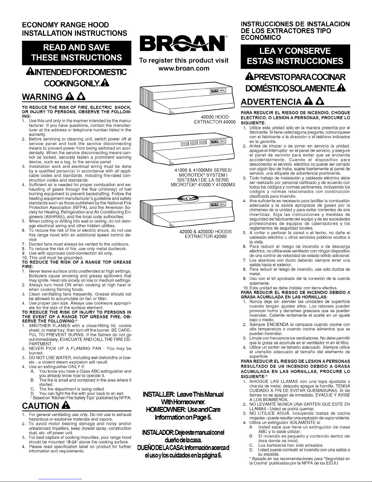
40000 HOOD
EXTRACTOR 40000
41000 & 41000MX SERIES/
MICROTEK ®SYSTEM I
SISTEMA I DE LA SERIE
MICROTEK ®41000 Y 41000MX
42000 & 42000D HOODS
EXTRACTOR 42000
INSTALLER:LeaveThisManual
Witht-bmeowner.
HOMEOWNER:UseandCare
InformationonPage5.
INSTALADOR:Dejeestemanuaiconel
due_odelacasa.
DUEl_iODELACASA:lnforrnadGnacercad
elusoyloscuidadosenlapaginaO.
PARA REDUCIR EL RIESGO DE INCENDIO, CHOQUE
ELECTRICO, O LESION A PERSONAS, PROCURE LO
SIGUIENTE:
1. Utilice esta unidad sOlo en la manera prescrita por el
fabricante. Si tiene usted alguna pregunta, comunfquese
con el fabricante a la direccion o el telefono indicados
en la garantia.
2. Antes de limpiar o de poner en servicio la unidad,
apague el interruptor en el panel de servicio, y asegure
el panel de servicio para evitar que se encienda
accidentalmente. Cuando el dispositivo para
desconectar el servicio electrico no puede ser cerrado
con algQn tipo de traba, sujete fuertemente al panel de
servicio, una etiqueta de advertencia prominente.
3. Todo trabajo de instalacion y cableado electrico debe
ser realizado por personal calificado y de acuerdo con
todos los codigos y normas pertinentes, incluyendo los
codigos y normas relacionados con construccion
clasificada para incendio.
4. Aire suficiente es necesario para facilitar la combustion
adecuada y la salida apropiada de gases por la
chimenea de la unidad y para evitar corrientes de aire
invertidas. Siga las instrucciones y medidas de
seguridad del fabricante del equipo y de las sociedades
profesionales de equipos de calentadores y los
reglamentos de seguridad locales.
5. A cortar o perforar la pared o el techo, no da_e el
cableado electrico u otros servicios p0blicos ocultos a
la vista.
6. Para reducir el riesgo de incendio o de descarga
electrica, no utilice este ventilador con ning0n dispositivo
de una control de velocidad de estado sOlido adicional.
7. Los abanicos con ducto deberAn siempre tener una
salida hacia el exterior.
8. Para reducir el riesgo de incendio, use s01o ductos de
metal.
9. Uso con el kit aprobado della conexiOn de la cuerda
solamente.
10. Esta unidad se debe instalar con tierra efectiva.
PARA REDUCIR EL RtESGO DE INCENDIO DEBIDO A
GRASA ACUMULADA EN LAS HORNILLAS:
1. Nunca deje sin atender las unidades de superficie
cuando tengan ajustes altos. Los reboses pueden
provocar humo y derrames grasosos que se pueden
incendiar. Caliente lentamente el aceite en un ajuste
bajo o medic.
2. Siempre ENCIENDA la campana cuando cocine con
alta temperatura o cuando cocine alimentos que se
puedan incendiar.
3. Limpie con frecuencia los ventiladores. No debe permitir
que la grasa se acumule en el ventilador ni en el filtro.
4. Utilice un sarten de tama¢_o adecuado. Siempre utilice
el utensilio adecuado al tama¢_o del elemento de
superficie.
PARA REDUCIR EL RIESGO DE LESION A PERSONAS
RESULTADO DE UN INCENDIO DEBIDO A GRASA
ACUMULADA EN LAS HORNILLAS, PROCURE LO
SIGUIENTE:*
1. AHOGUE LAS LLAMAS con una tapa ajustada o
charola de metal, despues apague la hornilla. TENGA
CUIDADO A FIN DE EVlTAR QUEMADURAS. Si las
llamas no se apagan de inmediato, EVACUE Y AVlSE
A LOS BOMBEROS.
2. NO LEVANTE NUNCA UNA SARTEN QUE ESTE EN
LLAMAS - Usted se podra quemar.
3. NO UTILICE AGUA, incluyendo toallas de cocina
mojadas - puede resultar una explosion de vapor violenta.
4. Utilice un extinguidor SOLAMENTE si:
A. Usted sabe que tiene un extinguidor de clase
B. El incendio es peque¢_o y contenido dentro del
C. Los bomberos hart sido avisados.
D. Usted puede combatir el incendio con una salida a
* Basado en las recomendaciones para "Seguridad en
la Cocina" publicadas por la NFPA de los EEUU.
ABC y Io sabe utilizar.
Area donde se iniciO.
su espalda.
Page 2
TOOLS AND
MATERIALS REQUIRED
[] Drill, electric or ratchet drive
[] 1/8" Drill bit for drilling pilot holes
[] 1-1/4" wood bit for drilling electrical wiring access
hole
[] One straight blade and one phillips head screw-
driver
[] Pliers
[] Pencil and ruler and/or tape measure
[] Saber saw or keyhole saw for cutting 1" x 2" wood
strips to length and cutting wall or cabinet openings
[] Caulking, metal snips, duct tape, duct (with elbows
and transition, if necessary) and roof or wall cap,
as required
[] Electrical wiring and supplies of type to comply
with local codes
The following materials are required only for installa-
tions on recessed bottom kitchen cabinets:
[] Two 1" x 2" x 12" (approximate length) wood strips
(purchase locally)
[] Four 1-1/4" long flat head wood screws (purchase
locally)
PLANNING DUCTWORK
INSTALLATION
(This section for 40000 and 42000 hoods only. 41000
hoods skip this section and go on to "Prepare the
Hood'.')
Begin planning ductwork by deciding where the duct
will run between the range hood and the outside. For
best performance, use the shortest possible duct run
and a minimum number of elbows. There are several
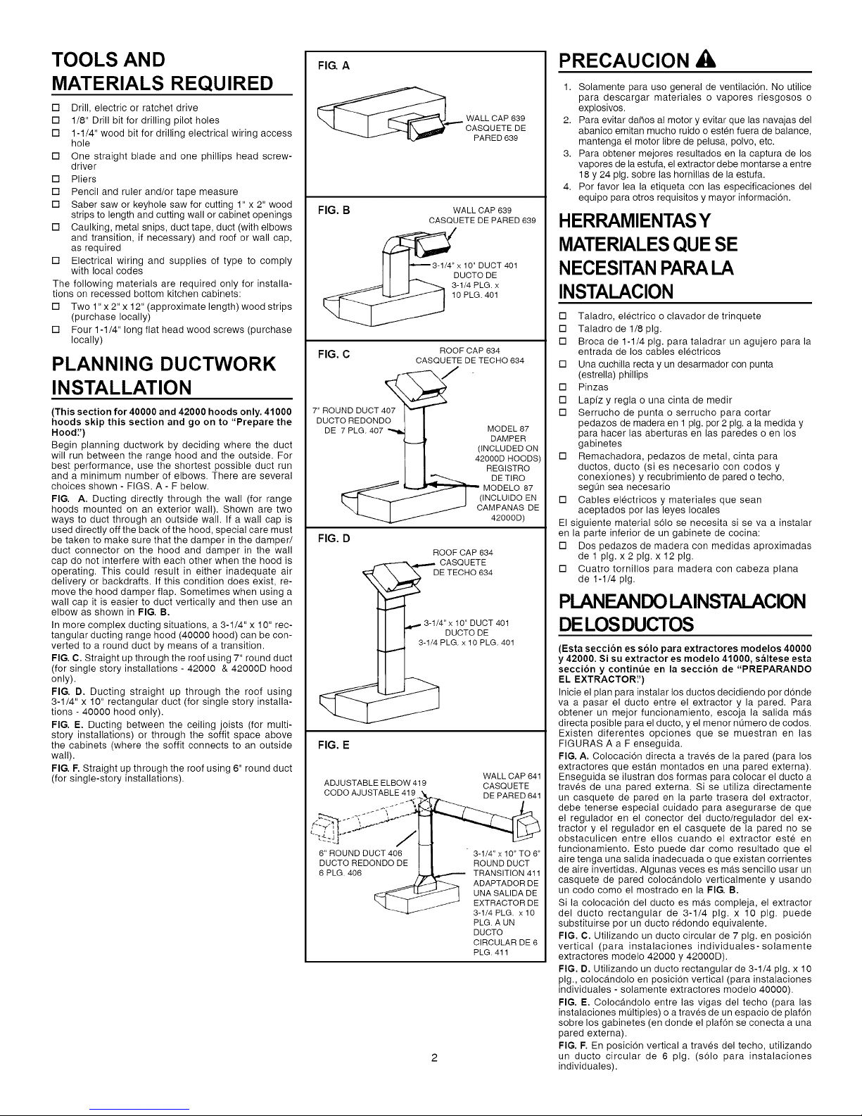
choices shown - FIGS. A - F below.
FIG. A. Ducting directly through the wall (for range
hoods mounted on an exterior wall). Shown are two
ways to duct through an outside wall. If a wall cap is
used directly off the back of the hood, special care must
be taken to make sure that the damper in the damper/
duct connector on the hood and damper in the wall
cap do not interfere with each other when the hood is
operating. This could result in either inadequate air
delivery or backdrafts. If this condition does exist, re-
move the hood damper flap. Sometimes when using a
wall cap it is easier to duct vertically and then use an
elbow as shown in FIG. B.
In more complex ducting situations, a 3-1/4" x 10" rec-
tangular ducting range hood (40000 hood) can be con-
verted to a round duct by means of a transition.
FIG. C. Straight up through the roof using 7" round duct
(for single story installations - 42000 & 42000D hood
only).
FIG. 13. Ducting straight up through the roof using
3-1/4" x 10" rectangular duct (for single story installa-
tions - 40000 hood only).
FIG. E. Ducting between the ceiling joists (for multi-
story installations) or through the soffit space above
the cabinets (where the soffit connects to an outside
wall).
FIG. F. Straight up through the roof using 6" round duct
(for single-story installations).
FIG. A
WALL CAP 639
OASQUETE DE
PARED 639
FIG. B WALL CAP 639
FIG. C ROOF CAP 634
7"DROTUoNDDDUCT4_7_ /
DE 7 PLG.407 '_ i MODEL 87
_ I (INCLUIDO EN
FIG. D
CASQUETE DE PARED 639
xl0"DUCT 401
DUCTODE
3-1/4 PLG. x
10 PLG. 401
CASQUETE DETECHO 634
I I (iNCLUDED ON
I I 42000D HOODS)
I I REGISTRO
I I _ DETIRO
_ MODELO 87
I / CAMPANASDE
ROOF CAP 634
'_.4.-,-"" CASQUETE
_ DE TECHO 634
3-1/4"x 10" DUCT 401
pDGU?TOoDp_G.401
DAMPER
42000D)
FIG. E
ADJUSTABLE ELBOW 419 CASQUETE
CODO AJUSTABLE 419 DE PARED 641
6" ROUND DUCT 406
DUCTO REDONDO DE
6 PLG. 406
WALL CAP 641
3-1/4" x 10" TO 6"
ROUND DUCT
TRANSITION 411
ADAPTADOR DE
UNA SALIDA DE
EXTRACTOR DE
3-1/4 PLG. x 10
PLG. A UN
DUCTO
CIRCULAR DE 6
PLG. 411
PRECAUCION
1. Solamente para uso general de ventilacion. No utilice
para descargar materiales o vapores riesgosos o
explosivos.
2. Para evitar daOos al motor y evitar que las navajas del
abanico emitan mucho ruido o esten fuera de balance,
mantenga el motor libre de pelusa, polvo, etc.
3. Para obtener mejores resultados en la captura de los
vapores de la estufa, el extractor debe montarse a entre
18 y 24 pig. sobre las hornillas de la estufa.
4. Por favor lea la etiqueta con las especificaciones del
equipo para otros requisitos y mayor informacion.
HERRAMIENTASY
MATERIALES QUE SE
NECESITAN PARALA
INSTALACION
[] Taladro, electrico o clavador de trinquete
[] Taladro de 1/8 pig.
[] Broca de 1-1/4 pig. para taladrar un agujero para la
entrada de los cables electricos
[] Una cuchilla recta y un desarmador con punta
(estrella) phillips
[] Pinzas
[] Lapfz y regla o una cinta de medir
[] Serrucho de punta o serrucho para cortar
pedazos de madera en 1 pig. por2 pig. a la medida y
para hacer las aberturas en las paredes o en los
gabinetes
[] Remachadora, pedazos de metal, cinta para
ductos, ducto (si es necesario con codos y
conexiones) y recubrimiento de pared o techo,
segOn sea necesario
[] Cables electricos y materiales que sean
aceptados por las leyes locales
El siguiente material sOlo se necesita si se va a instalar
en la parte inferior de un gabinete de cocina:
[] Dos pedazos de madera con medidas aproximadas
de 1 pig. x 2 pig. x 12 pig.
[] Cuatro tornillos para madera con cabeza plana
de 1-1/4 pig.
PLANEANDOLAINSTALACION
DELOSDUCTOS
(Esta seccion es s61o para extractores modelos 40000
y 42000. Si su extractor es modelo 41000, saltese esta
seccibn y contint_e en la seccion de "PREPARANDO
EL EXTRACTOR'.')
Inicie el plan para instalar los ductos decidiendo por donde
va a pasar el ducto entre el extractor y la pared. Para
obtener un mejor funcionamiento, escoja la salida mdts
directa posible para el ducto, y el menor nOmero de codos.
Existen diferentes opciones que se muestran en las
FIGURAS A a F enseguida.
FIG. A. ColocaciOn directa a traves de la pared (para los
extractores que estan montados en una pared externa).
Enseguida se ilustran dos formas para colocar el ducto a
traves de una pared externa. Si se utiliza directamente
un casquete de pared en la parte trasera del extractor,
debe tenerse especial cuidado para asegurarse de que
el regulador en el conector del ducto/regulador del ex-
tractor y el regulador en el casquete de la pared no se
obstaculicen entre ellos cuando el extractor este en
funcionamiento. Esto puede dar como resultado que el
aire tenga una salida inadecuada o que existan corrientes
de aire invertidas. AIgunas veces es ma.s sencillo usar un
casquete de pared colocandolo verticalmente y usando
un codo como el mostrado en la FIG. B.
Si la colocacion del ducto es ma.s compleja, el extractor
del ducto rectangular de 3-1/4 pig. x 10 pig. puede
substituirse por un ducto redondo equivalente.
FIG. C. Utilizando un ducto circular de 7 pig. en posiciOn
vertical (para instalaciones individuales-solamente
extractores modelo 42000 y 42000D).
FIG. D. Utilizando un ducto rectangular de 3-1/4 pig. x 10
pig., coloc_tndolo en posicion vertical (para instalaciones
individuales - solamente extractores modelo 40000).
FIG. E. Colocandolo entre las vigas del techo (para las
instalaciones multiples) o a traves de un espacio de plafon
sobre los gabinetes (en donde el plafon se conecta a una
pared externa).
FIG. F. En posicion vertical a traves del techo, utilizando
un ducto circular de 6 pig. (s01o para instalaciones
individuales).
Page 3

PREPARE THE HOOD FiG.F
1. Unpack hood and check contents. You should re-
ceive:
1 - Aluminum Filter (40000 and 42000 & 42000D
hoods only)
1 - 3-1/4" x 10" Damper/Duct Connector (mounted
inside of hood for shipping only) (40000
hood only)
1 - Ductfree Microtek ® System I Filter (41000
hood only)
1 - 7" Round Damper (42000D hoods only.)
2. Remove wiring box cover. Under cover find:
1 - Plastic Bag containing loose mounting hard-
ware
3. Remove top or rear electrical knockout. (FIG. 2)
4. (40000 hood ONLY) Remove duct knockout. In-
sert screwdriver under edge of knockout, break
tabs, and peel knockout back with pliers. (FIG. 3)
5. (40000 hood ONLY) Install damper/duct connec-
tor over opening made in STEP 4. Use #8B sheet
metal screws provided. (FIG. 3)
(42000 hood ONLY) Install Model 87 round damper
(purchase separately) over opening intop of hood.
(42000D hood ONLY - Install 7" round damper (in-
cluded) over opening on top of hood.
3-1/4" x 10" TO 6" ROUND
DUCT TRANSITION 411
ADAPTADOR DE UNA
SALIDA DE EXTRACTOR
DE
3-1/4 PLG. x 10 PLG. A UN
DUCTO CIRCULAR
FIG. 1 CUBIERTA DE LA CAJA DE CABLEADO
DUCTFREE
MICROTEK®
PREPARE THE
INSTALLATION LOCATION
Omit STEP 1 if hood will be installed under cabinets
with flush bottom.
1. (For installation on recessed bottom cabinets only)
Attach a wood filler strip at each side of recessed
area under cabinet. Use two 1" x 2" strips cut to
length. If recess is deeper than 1" use thicker strips.
Attach strips with 1-1/4" wood screws, 3" from each
end of strip. See FIG. 4.
2. Measure and mark the following (FIGS. 5A & 5B):
a.) Electrical wiring opening in wall or cabinet.
b.) Duct opening in wall or cabinet (40000, 42000
& 42000D hoods ONLY).
WARNING
WHEN CUTTING OR DRILLING INTO WALL OR
CABINET, BE CAREFUL NOT TO CUT EXISTING
3. Use 1-1/4" bit to drill opening for electric wiring.
4. Cut out duct opening in wall or cabinet with saber
saw or keyhole saw.
5. Center hood in installation opening and trace key-
hole slots onto wood filler strips on cabinet bottom.
6. Screw four #10 x 7/8 wood screws into exact center
of narrow end of traced keyhole slots. Allow 3/8" of
screws to project, so that hood can be fitted into place
later.
(SOLO
_OS CONNECTOR (40000
PARALO6 S DAMPER/DUCT
40000, 42000
Y42000D) T ROUND DAMPER CONECTOR DEL
FIG. 2
I
]ELECTRICAL WIRING.
FIG. 3
ELECTRICAL
KNOCKOUTS
TAPONES
FIG. 4
...... ¢',',,
ROOF CAP 634
CASQUETE DE TECHO 634
6" ROUND DUCT 406
REDONDO
DE 6 PLG. 406
WIRING BOX COVER
HOOD ONLY)
(42000D HOOD ONLY) DUCTO/REGULADOR
REGULADOR REDONDO (SOLO PARA EL
DE 7 PULG. (SOLO PARA MODELO 40000)
EL MODELO 42000D)
HINGE PINS
PASADORES DE
3ISAGRA
DUCT
KNOCKOUTS
TAPONES DEL
DUCTO
/" , \
PREPARANDO
EL EXTRACTOR
1. Desempaque el extractor y revise el contenido de la
caja. Usted debe encontrar:
1 - Filtro de aluminio (solamente extractores modelos
40000, 42000 y 42000D)
1 - Conector de ducto/regulador de 3-1/4 pig. x 10
pig. (montado dentro del extractor para facilitar
el embarque) (solamente extractores modelo 40000)
1 - Sistema de filtro Ductfree Microtek ® System
1 - Regulador de 7 pulg. (campanas de 42000D
solamente.)
2. Retire la cubierta de la caja de cableado. (FIG. 1)
Bajo la cubierta encontrara:
1-Bolsa de pldtstico que contiene las piezas
necesarias para la instalacion
3. Retire el tap6n electrico trasero superior. (Fig. 2)
4. (SOLAMENTE extractores modelo 40000) Retire el
tapon trasero superior. Coloque un desarmador
debajo del extremo del tapon, rompa los apendices y
retire el tap6n con unas pinzas. (FIG. 3)
5. (SOLAMENTE extractores modelo 40000) Instale el
conector del ducto/regulador sobre la abertura hecha
en el PASO 4. Utilice el tornillo de lamina negra #8B
proporcionado en la bolsa de plastico. (FIG. 3)
(SOLAMENTE extractores modelo 42000) Instale el
regulador Modelo 87 (comprado por separado) sobre
la abertura en la parte superior del extractor.
(Campana de 4200D SOLAMENTE - Instale regulador
de 7 pulg. (incluido) sobre la abertura en la tapa de la
campana.
ACONDICIONE EL LUGAR
DE LA INSTALACION
Si el extractor va a ser instalado bajo gabinetes con suelo
nivelado, omita el PASO 1.
1. (Solamente para la instalacion en los gabinetes con
espacios libres) Coloque una pieza de madera en cada
uno de los lados para rellenar el Area libre debajo del
gabinete. Utilice dos tiras de madera de 1 pig. x 2 pig.
de Iongitud. Si el Area libre tiene mas de 1 pig. de
profundidad, utilice piezas de madera m_ts gruesas.
Ajuste las piezas con tornillos para madera de 1-1/4
pig., a 3 pig. de los extremos. Consulte la FIG. 4.
2. Mida y marque Io siguiente (FIGS. 5A y 5B):
a.) La abertura del cableado electrico en la pared
o el gabinete.
b.) La abertura para el ducto en la pared o el gabinete
(SOLAMENTE extractores modelos 40000, 42000
y 42000D).
CUANDO ESTE CORTANDO O PERFORANDO LA /
PARED O EL GABINETE, ASEGURESE DE NO
CORTAR EL CABLEADO ELECTRICO EXlSTENTE.
3. Utilice un taladro de 1-1/4 pig. para hacer la abertura
para el cableado electrico.
4. Haga un corte en la pared o el gabinete, para la entrada
del ducto, con un serrucho ouna sierra de punta o de
calador. (Si la pared es de concreto, haga las
operaciones necesarias para la instalacion.)
5. Centre el extractor en la entrada de la instalaci6n y
marque las ranuras en las piezas de madera que
rellenan el espacio libre en la parte inferior del gabinete.
6. Ajuste 4 tornillos para madera #10 x 7/8 justo en el
centro del extremo angosto de las ranuras marcadas.
Permita que los tornillos salgan 3/8 pig. para que el
extractor pueda ser colocado en su lugar.
ADVERTENCIA
/
J
........................
,/",,:,.... i//
Page 4

INSTALL THE
DUCTWORK
(This section for 40000 and 42000 hoods only. 41000
hoods skip this section and go on to "Install Range
Hood'.')
NOTE
These instructions will follow plans made on
Page 2. Start at the exterior and run ductwork
back to the range hood.
For best possible performance, use the short-
est possible duct run and a minimum number
of elbows. Do not vent a range hood into an at-
tic space. A buildup of grease in the attic could
become a fire hazard.
Use only metal ductwork. DO NOT USE PLAS-
TIC DUCT. Assemble duct run securely so that
in case of a grease fire on the range, the fire
will be contained inside metal ductwork.
Tape all duct connections.
1. Follow appropriate directions below for type of duct
run you install.
a.) Wall Cap Discharge; (FIG. 7) Use saber saw
or keyhole saw to cut hole slightly larger than
duct size used so that duct will line up easily
with damper/duct conector on hood. Install
casing strips if cap will be installed on siding.
Attach required amount of duct to wall cap and
run duct back to hood. Fasten cap to wall and
caulk well.
b.) Roof Cap Discharge; (FIG. 8) Cut a hole in
roof slightly larger than duct size being used.
Run ductwork down to hood location. Leave
3/4" of duct projecting above roof surface on
high side.
Trim duct parallel to roof pitch and seal all
around duct with roof cement.
Carefully trim shingles and slide back of roof
sheet under shingles. Nail roof sheet to roof un-
der shingles at top two corners and two sides.
Nail sheet directly to roof in four places at bot-
tom.
Using roof cement, seal all nail heads and
shingles which were cut or lifted. Do not seal
bottom edge of roof sheet.
INSTALL RANGE HOOD
TURN OFF THE PROPER CIRCUIT AT THE SER-
VICE ENTRANCE BEFORE WIRING THIS RANGE
I WARNING I
HOOD.
1. Run electric wiring through hole drilled in wall or
cabinet. Split wiring for 6" and install proper con-
nector for type of wire used. (FIG. 9)
2. Position hood so that:
a.) Wiring is routed through knockout opening
(FIG. 10) (MX Series Only: Use grommet sup
plied in parts bag.)
b.) Large part of keyhole slots fit over hood mount-
ing screws. (FIG. 10)
c.) Damper/duct connector slides into ductwork.
(40000, 42000 and 42000D hoods only)
3. Adjust hood so that hood front is flush with cabi-
net frame.
4. Tighten hood mounting screws firmly.
5. Fasten wiring to hood with proper electrical con-
nector for type of wire being used.
ALL ELECTRICAL CONNECTIONS MUST BE tN
ACCORDANCE WITH LOCAL CODES, ORDI-
NANCES, OR NATIONAL ELECTRICAL CODE. IF
YOU ARE UNFAMILIAR WITH METHODS OF IN-
STALLING ELECTRICAL WIRING, SECURE THE
SERVICES OF A QUALIFIED ELECTRICIAN.
6. Strip 1/2" of insulation from wires. Connect white
to white, black to black, and green to prepared
hole with green ground screw provided. (FIG. 11 )
7. Replace wiring box cover and screw. Make sure
that all wiring is safely contained inside.
8. Install light (75 Watt maximum). For easier instal-
lation, squeeze plastic lens and remove it from
hood. Remember to reinstall lens. (FIG.12)
9. Turn on power and check operation of fan and
light. Make sure that damper operates freely.
WARNING
FIG. 5A
L__ _ °_
\
FIG. 5B
MODELO 42000 _._
FIG. 6
/ \
FIG. 7
FIG. 8
.... _. : I \ f I
, '<_.......... l
7,.t ! /
/
\ _ _ _ __.i_ //_ FIEZAOE
-'-- 6/// AOERA
_i_l, ..' --t_ I
CENTER LINE I ' . / _" ] =
,oooW, TTEAOBCENTROS....
ANCHO DEL EXTRACTOR
CENTROS
SOFFIT
GABINETE
CABINET
GABINETE
MODELOS 40000
ROOF CAP
CASQUETE DE
CASQUETE
DE PARED
ALL CAP
INSTALACION DEL DUCTO
(Esta secci6n es solamente para los extractores
modelos 40000 y 42000. Los modelos 41000 pueden
saltarse esta secci6n y continuar en la "INSTALACION
DEL EXTRACTOR'.')
Estas instrucciones seguir_n los planes descritos
en la p_g 2. Comience a trabajar del exterior al in-
terior para conectar el ducto con el extractor.
Para obtener un mejor funcionamiento del extrac-
tor, procure que la salida del ducto sea la m&s
directa y que tenga el menor numero de codos.
No permita que la salida del extractor quede en un
desv_n. Si seforma una capa de grasa en el desv_n
puede ser peligroso y causar un incendio.
Utilice solamente ductos de metal. NO USE
DUCTOS DE PLASTtCO. Ensamble el ducto
firmemente para que en caso de que se prenda
debido a la grasa, el fuego se contenga dentro del
ducto de metal. Coloque cinta de aislar en todas
las conexiones del ducto.
1. Siga las incicaciones adecuadas para el tipo de ducto
que vaya a instalar.
a.) Salida del casquete de pared: (FIG. 7) Utilice
un serruoho o una sierra de calador para cortar
un orificio un poco m_ts grande que el tama_o
del ducto, para poder acomodar facilmente el
ducto con el conector del ducto/regulador en el
extractor. Si el casquete se va a instalar en un
lado, instale las tiras del marco. Fije la cantidad
requerida del ducto en el casquete de pared y
acomode el ducto en el extractor. Ajuste el
casquete a la pared. Fijelo con un martillo. (Si la
pared es de concreto u otro material, ejecute las
operaciones necesarias para obtener los mismos
resultados.)
b.) Salida del casquete por el techo: (FIG. 8) Haga un
orificio en el techo, ligeramente ma.sgrande que
la circunferencia del ducto que se esta usando.
Coloque el ducto debajo del lugar donde va el
extractor. Deje que 3/4 pig. del ducto sobresalgan
per encima de la superficie en el lado alto del techo.
Ajuste el ducto paralelamente con la inclinacion
del techo y selle alrededor del tubo con cemento
para techos o tejados.
Empareje las tejas con cuidado y deslice la placa
del tejado que esta debajo de las tejas. Clave la
placa del tejado a la parte de techo que esta
bajo las tejas en las dos esquinas y los dos
lados superiores. Clave la placa directamente
al tejado en cuatro extremos en la parte inferior.
Utilizando cemento para tejado, selle todas las
cabezas de los clavos y las tejas que fueron
cortadas o levantadas. No selle el extremo infe-
rior de la placa del tejado. (Si el techo es de
concreto haga las operaciones necesarias para
obtener los mismos resultados.)
INSTALACION
DEL EXTRACTOR
DESCONECTE EL CIRCUITO EN LA ENTRADA DE
SERVICIO ANTES DE CONECTAR EL CABLEADO
i ADVERTENCIA I
DEL EXTRACTOR.
1. Pase el cableado electrico a traves de un orificio en
la pared o el gabinete. Separe el cableado a 6 pig. e
instale el conector apropiado para el tipo de cable
usado. (FIG. 9)
*'10-15/16"FOR 24"RANGE HOOD
10-15/16PLG.PARA EXTRACTOR DE 24PLG.
13-15/16"FOR30" _GE HOOD
13-15/16PLG.PARA EXTRACTOR DE 30PLG.
16-15/16"FOR36" _GE HOOD
16-15/16PLG.PARA EXTRACTOR DE 36PLG.
19-15/16"FOR42" _GE HOOD
19-15/16PLG.PARA EXTRACTOR DE 42PLG.
NOTA
Page 5

USE AND CARE
SWITCHES
The fan and light are each controlled by a rocker
switch. The light switch has two positions, "ON" and
"OFF."The fan switch has three positions - "HIGH,"
"LOW" and "OFF." ("OFF" is the middle position.)
FILTERS
40000, 42000 & 42000D Hoods Only:
Remove aluminum filter by turning filter retainer to
one side. (FIG. 13) Filter should be washed once a
month in a hot detergent solution. Aluminum filters
are dishwasher safe. When installing filter, make sure
that filter slides under retaining tabs on back of fan
housing. Turn filter retainer so that arrows on retainer
point toward front and back of hood.
41000 Hoods Only:
The 41000 hood is equipped with a ductfree filter. Re-
move filter by turning filter retainer to one side. (FIG.
13) The ductfree filter is not washable, and will last up
to twelve months with normal use. Replace the filter
when colored side becomes noticeably dirty or discol-
ored.
When installing filter, make sure that filter slides un-
der retaining tabs on back of fan housing. MAKE
SURE THAT COLORED SIDE OF FILTER IS NEXT
TO FAN WHEN FILTER IS INSTALLED. Turn filter
retainer so that arrows on retainer point toward front
and back of hood.
ALWAYS DISCONNECT ELECTRIC POWER BE-
FORE SERVICING RANGE HOOD.
FAN ASSEMBLY
Remove filter. Remove two screws holding motor
bracket to range hood, and unplug fan assembly. Be
careful not to allow fan assembly to drop when screws
are removed. (FIG. 14)
CLEANING
Clean your hood with a mild detergent suitable for
painted surfaces. DO NOT USE ABRASIVE CLOTH,
STEEL WOOL PADS OR SCOURING POWDERS.
Fan assembly may be vacuumed. Fan assembly is
permanently lubricated, and never needs oiling.
HOW TO AVOID A COMMON RANGE-TOP
GREASE FIRE
• Your range hood provides a protective barrier
between the cooking surface and the cabinets.
• Keep fan, filters and grease laden surfaces
CLEAN according to instructions.
• Always turn hood ON when cooking at high heat
to keep the cooking area and the hood cooler.
• Use high heat settings only when necessary.
• Never leave cooking surface unattended. Boil-
over causes smoking and greasy spillovers that
may ignite.
• Always use adequate-sized utensils.
• If preparing flaming foods, such as Cherries Ju-
bilee, always turn hood ON to HIGH to prevent
a high heat situation which can cause damage
or fire.
HOW TO EXTINGUISH A COMMON RANGE-
TOP GREASE FIRE
• Never pick up a flaming pan. If dropped, flames
can spread quickly.
• DO NOT USE WATER! A violent steam explo-
sion may result. Wet dishcloths or towels are
also dangerous.
• Smother flames with a close fitting lid, cookie
sheet or metal tray.
• Flaming grease can also be extinguished with
baking soda or a multi-purpose dry chemical
extinguisher.
• Turn off surface units - if you can do so without
getting burned.
WARNING
FIG. 9
i
MX Series Only
FIG. 10 ,_
FIG. 11
_TORNILIODEI]ERRAVERDE _'_ L "_X ,_......,.._(
STAR LOCKNUT GROUNDING BRACKET
TUERCA DE FUAOIQN MENSULAS DE TIERRA
DE ESTRELLA
FIG. 12
FIG. 13
FILTER / ._._
APENDICEB
GROMMET/ _
OJAL REFORZADO _J"
ELECTRICAL ,,,,,,,,,,,,,,,_=_
KNOCKOUTS
ELECTRICOS
5
2. Coloque el extractor para que:
a.) El cableado salga por la salida del tapon. (FIG .10)
(Serie MX solamente: Utilice el ojal reforzado
provisto en bolso de las piezas.)
b.) Las partes grandes de las ranuras se ajustan en
los tornillos de la montura del extractor. (FIG. 10)
c.) El conector del ducto/regulador se deslice dentro
del ducto. (SOLAMENTE para extractores 40000,
42000 y 42000D)
3. Ajuste el extractor para que la parte del frente se nivele
E_
con el gabinete.
4. Ajuste los tornillos de la montura del extractor con
firmeza.
5. Ajuste el cableado al extractor con el conector electrico
adecuado para el tipo de cable que se va a utilizar.
TODAS LAS CONEXIONES ELECTRICAS DEBEN SEn
REALIZADAS DEACUERDO CON LOS CODI-GOS LO-
CALES, REGLAMENTOS Y CODIGOS ELECTRICOS
NACtONALES. SI NO ESTA FAMILIAIZADO CON LOS
METODOS DE INSTALACION DE CABLEADO
ELECTRICO, CONTRATE LOS SERVICIOS DE UN
ELECTRICISTA CALIFICADO.
6. Pele 1/2 pig. de aislante de los cables. Conecte los
cables, blanco con blanco, negro con negro y el verde
con el orificio hecho con el tornillo de tierra verde,
proporcionado en la bolsa. (FIG. 11)
7. Coloque de nuevo la tapa de la caja del cableado y el
tornillo. Aseg0rese de que todo el cableado quede bien
contenido en el interior.
8. Instale el foco (maximo 75 watts). Para Iograr una
instalacion mas sencilla, presione los protectores
plasticos y retffelos del extractor. Recuerde reinstalar
los protectores. (FIG. 12)
9. Conecte la corriente para revisar la operacion del
abanico y la luz. Asegdirese de que el regulador funcione
con libertad.
ADVERTENCtA
USO Y CUIDADOS
LOS INTERRUPTORES
El abanico y el foco estan controlados individualmente
por un interruptor balancin. El interruptor del foco tiene
dos posiciones, ENCENDIDO ("ON") y APAGADO ("OFF").
El interruptor del abanico tiene tres posiciones - ALTA
("HIGH"), BAJA ("LOW") y APAGADO ("OFF"). (El
interruptor para APAGADO esta en la posici6n de en
medic.)
LOS FILTROS
Solamente los extractores modelo 40000, 42000 y42000D:
Retire el filtro de aluminio girando el contenedor del filtro
hacia un lado. (FIG. 13) El filtro debe lavarse una vez al
mes en una solucion jabonosa caliente. Los filtros de
aluminio se pueden lavar en la lavadora de platos. Cuando
instale un filtro, aseg0rese de que el filtro se deslice debajo
de los apendices en la parte trasera del compartimiento
del abanico. Gire el contenedor del filtro para que las
flechas del contenedor apunten hacia el frente y la parte
trasera del extractor.
Solamente los extractores modelo 41000:
El extractor 41000 esta equipado con un filtro sin ducto.
Retire el filtro girando el contenedor del filtro hacia un
lado. (FIG. 13) El filtro sin ducto no se puede lavar, y durardt
hasta doce meses con un uso normal. Coloque de nuevo
el filtro cuando el lado de color se tome sucio o se
decolore.
Cuando instale un filtro, aseg0rese de que el filtro se
deslice por debajo de los apendices en la parte trasera
del compartimiento del abanico. ASEGURESE DE QUE
EL LADO COLOREADO DEL FILTRO QUEDE
ENSEGUIDA DEL ABANICO, CUANDO EL FILTRO SEA
INSTALADO. Gire el contenedor del filtro para que las
flechas de el contenedor apunten hacia el frente y la parte
trasera del extractor.
ADVERTENCIA
TRICIDAD ANTES DE DARLE SERVICIO DE
I DESCONECTE SIEMPRE EL CABLE DE ELEC- I
MANTENIMIENTO AL EXTRACTOR.
EL ENSAMBLE DEL ABANICO
Retire el filtro. Retire los dos tornillos que sostienen el
motor en el extractor, y desconecte el ensamble del
abanico. Asegurese de no permitir que el abanico se caiga
cuando retire los tornillos. (FIG. 14)
LA LIMPIEZA
Limpie su extractor con un detergente suave que sea
adecuado para superficies pintadas. NO UTILICE PIEZAS
DE TELA ABRASIVAS, FIBRAS 0 DETERGENTE.
El abanico puede ser aspirado. El ensamble del abanico
esta lubricado permanentamente y no necesita que se le
agregue aceite.
I
I
Page 6

Replacement parts
can now be ordered
on our website.
Please visit us at
www.aroan.com
FIG. 14
SCREWS
TORNtLLOS /_
21_ Las piezas de recambio se
e
12
/ nuestro Web site. Visitenos
15 .... _;L_-"_T por favor en
pueden ahora pedir en
www.groan.com
13 _ 17 18
COMO EVITAR QUE OCURRA UN INCENDIO
DEBIDO A LA GRASA QUE SE ACUMULA EN UN
EXTRACTOR COMUN
• Su extractor proporciona una barrera protectora en-
tre la superficie para cocinar y los gabinetes.
• Mantenga el abanico, los filtros y las superficies
donde se acumula la grasa LIMPIAS conforme a
las instrucciones.
• ENCIENDA siempre el extractor cuando este
cocinando a fuego alto para mantener el area para
cocinar y el extractor limpios.
• Utilice las hornillas de fuego alto solamente cuando
sea necesario.
• No deje las hornillas de la estufa sin atenci0n
cuando este cocinando. El vapor o el aceite
que salpique puede ocasionar un incendio
o acumulaci6n de humo.
• Siempre utilice los utensilios del tama¢_o adecuado.
• Siesta preparando alimentos fiameados, como las
Cerezas a la Jubilee, ENCIENDA siempre el ex-
tractor en ALTO para evitar que el calor pueda
causar algQn da_o o un incendio.
COMO EXTINGUIR UN INCENDIO EN UN EXTRAC-
TOR COMUN
• No levante nunca una sarten que este en llamas.
Si se le cae, las llamas se pueden extender
rapidamente.
• iNO UTILICE AGUA PARA APAGARLO! Puede
ocasionar una explosi6n de vapor. Las toallas de
cocina mojadas tambien son peligrosas.
• Ahogue las llamas con una tapa ajustada o una
charola.
• Las llamas provocadas por la grasa tambien se
pueden apagar con bicarbonato de sodio o un
extinguidor qufmico.
• Apague las hornillas - si puede hacerlo sin
quemarse.
10
6
KEY NO. PART NO. DESCRIPTION
NO. CODIGO NO. PIEZA
1 98006621 Outlet Box Cover
2 99170245 #8 x 3/8 Sheet Metal Screw*
3 99270987 Bulb Holder with Wires
4 99110437 Light Lens
5 97011217 Screw/Nut Kit (includes 2 - #10-16 x .500 screws
6 99020248 Fan Blade
7 99260428 #6-32 Locking Nuts* (2 Required)
8 98005568 Motor Mounting Bracket
9 97012248 Motor Assembly (Includes Key Nos. 6, 7, & 8)
10 97006931 Aluminum Filter
11 99420472 Filter Retainer
12 99150415 #8B x 1/4 Hex Head Sheet Metat Screws* (2 Required)
13 98005221 Damper Flap
14 99100379 Damper Bushing
15 97005544 Damper Assembly (includes Key Nos. 13, 14 and 21)
16 97010709 Nameplate - Black
17 97016970 2-Speed Motor Switch - Black (includes Key No. 18)
18 97016970 Light Switch - Black (Includes Key No. 17)
19 97005678 Motor Receptacle with Wires
20 99150471 #10-32 x 1/2 Green Ground Screw*
21 99100408 Damper Bumper
** - - - - Light Bulb, 75 Watt (not included)*
99090881 Nameplate - White
97016971 2-Speed Motor Switch - White (Includes Key No. 18)
97016971 Light Switch - White (includes Key No. 17)
Order service parts by "PART NO." - NOT by "KEY NO."
* Standard Hardware. May be purchased locally.
** Not Illustrated.
and 2 - #10-16 sheet metat nuts)
SERVICE PARTS
40000 SERIES 3-1/4" X 10" DUCTED HOOD
PIEZAS DE SERVICIO
EXTRACTOR CON DUCTO DE 3-1/4 PLG. X
10 PLG. MODELO 40000
DESCRIPCION
Cubierta de la caja de la toma de corriente
Tornillos de metal para I_.mina #8 x 3/8"
Contenedor del bulbo con cableado
Cubierta protectora det foco
Paquete de torni!los/tuercas (inctuye 2 tomillos #10-16 x
0.500 y 2 tuercas de metal de lamina #10-16)
Navajas det abanico
Tuercas #6-32* (2)
Soporte de montura del motor
Motor (incluye piezas 6, 7 y 8)
Filtro de aluminio
Contenedor det filtro
Tornillos de metal de cabeza hexagonal #8B x 1/4" (2)
Protecci6n del regulador
Forro de metal del regulador
Ensamblado det regulador (incluye piezas 13, 14 y 21)
R6tulo - Negro
R6tulo - Blanco
Interruptor del motor de 2 velocidades - Negro (inctuye pieza18)
Interruptor del motor de 2 velocidades - Blanco (incluye pieza18)
Interruptor del foco - Negro (inctuye pieza17)
Interruptor del foco - Blanco (incluye pieza17)
Recipiente del motor con cableado
Tornillo de tierra verde #10-32 x 1/2"
Defensa det regulador
Bulbo, 75 watts* (no incluido)
Encargue )iezas de servicio per "NO. PIEZA" - NO por "NO. CODIGO".
* Piezas estandar. Se pueden comprar Iocalmente.
** No se muestran.
Page 7

SERVICE PARTS
PIEZAS DE SERVICIO
41000 & 41000MX SERIES
MICROTEK ®SYSTEM I
Replacement parts
can now be ordered
on our website.
Please visit us at
www.Broan.com
10
5 6
SISTEMA MICROTEK ® I
SERIE 41000 Y 41000MX
14
12
Las piezas de recambio se
nuestro Web site. Visitenos
pueden ahora pedir en
por favor en
www.aroan.com
KEYNO. PARTNO. DESCRIPTION DESCRIPCION
NO.CODIGO NO.PIEZA
1
2
3
4
5
6
7
8
9
lO
11
12
15
16
17
Order service parts by "PART NO." - NOT by "KEY NO."
* Standard Hardware. May be purchased locally.
** Not Illustrated.
98OO6621
9917024,5
9_70¢6'7
99110437
97011217
99020287
99260428
98006568
97011_0
97016135
970076_6
99420472
97010709
9g0£0882
97016970
97016971
97016970
97016971
97005678
99150471
934O0038
OutletBox Cover
#8x 3/8 Sheet MetaJScrew*
BulbHdderwith Wkes
LightLens
Screw/Nut K_(Includes 2- #1O-16x .500screws
and2 -#10-16 sheet metal nuts)
FanBlade
#6-32 Locking Nuts* (2Required)
Motor MountingBracket
MotorAssembly, 410(30Series(IncludesKey Nos. 6, 7, &8)
MotorAssembly, 41000MX Series (includes Key Nos. 6, 7,& 8)
Ductfree Mic_otek"_'Fi_erSystem I
FilterRetainer
Nameplate- Black
Nameplate-Wh_e
2-Speed Motor Switch- Black(Includes Key No. 14)
2-Speed Motor Switch- White(IncludesKey No.14)
Light Switch -Black (IncludesKey No.13)
Light Switch -White (Includes Key No. 13)
Motor Receptacle withWires
#10-32x 1/2 Green Ground Screw*
_crrrr_
Light Bulb,75 Watt (notincluded)*
Encargue piezas de servicio por "NO. PIEZA" - NO por "NO. CODIGO".
* Piezas estandar. Se pueden comprar Iocalmente.
** No se muestran.
Cubierta de la caja de latoma de corriente
TornillosdemetaJparal_mina #6x 3/8'
Contenedordel bulbo con cableado
Cubierta protectoradetfoco
Paquete de tomillos!tuercas (inclwe 2 tomillos#10-16 x 0.500y 2
tuercas de metal del&mina#10-16)
Navajasdelabanico
Tuercas#6-32' (2)
Sopo_tedemonturadel motor
Ensemblaje del motor, Sefie 41000 (inctuyepiezas 6,7,y 8)
Ensemblajedel motor, Sefie 41000MX (induye piezas 6,7,y 8)
Blstemadefiltro Ductfree Microtek-"System I
Contenedordefitko
R6tulo- Negro
R6tulo- Blanco
Interrdptordel motor de2 veloddades -Negro (inclwe piezal 8)
Interruptordel motor de2 velocidades -Blanco (inclwe piezal 8)
Interruptordel foco -Negro (indwe piezal 7)
Interrdptordelfoco -Blanco (indwe piezal 7)
Recipientedel motor con cableado
Tomillode t_erraverde#10.32 x 1/2'
Ojatreforzado
Bulbo,75 watts* (no incluido)
Page 8

SERVICE PARTS
21
PIEZAS DE SERVICIO
42000 & 42000D 7" ROUND
DUCTED HOODS
Replacement parts
can now be ordered
on our website.
Please visit us at
www.Broan.com
10
KEY NO.
NO. CODIGO
1
2
3
4
5
6
7
8
9
10
11
16
17
18
19
20
21
Order service parts by "PART NO." - NOT by "KEY NO."
* Standard Hardware. May be purchased locally.
** Not Illustrated.
PART NO.
NO. PIEZA
98006621
99170245
99270987
99110437
97011217
99020272
99260428
98005568
97012248
97006931
99420472
97010709
99090881
97016970
97016971
97016970
97016971
97005678
99150471
97010792
17 18
16
1
DESCRIPTION DESCRIPCION
Outlet Box Cover
#8-18 x 3/8 Sheet Metal Screw*
Bulb Holder with Wires
Light Lens
Screw/Nut Kit (Includes 2 - #10-16 x .500 screws
and 2 - #10-16 sheet metal nuts)
Fan Blade
#6-32 Locking Nuts* (2 Required)
Motor Mounting Bracket
Motor Assembly (Includes Key Nos. 6, 7, & 8)
Aluminum Filter
Filter Retainer
Nameplate - Black
Nameplate - White
2-Speed Motor Switch - Black (Includes Key No. 18)
2-Speed Motor Switch - White (Includes Key No. 18)
Light Switch - Black (Includes Key No. 17)
Light Switch - White (Includes Key No. 17)
Motor Receptacle with Wires
#10-82 x 1/2 Green Ground Screw*
Light Bulb, 75 Watt (not included)*
T_Round Damper (Model 42000D only)
Encargue piezas de servicio por "NO. PIEZA" - NO por "NO. CODIGO".
* Piezas estandar. Se pueden comprar Iocalmente.
** No se muestran.
Cubierta de la caja de la toma de corriente
Torniilos de metat para I_tmina #8-18 x 318"
Contenedor del buibo con cabieado
Cubierta protectora del foco
Paquete de tomii!oe/tuercae (incluye 2 tornii!oe #10-16 x 0.500
y 2 tuercas de metaI de lamina #10-16)
Navajas del abanico
Tuercas #6-82* (2)
Soporte de montura det motor
Motor (incluye piezas 6, 7, y 8)
Filtro de alurninio
Contenedor deI fiitro
R6tulo - Negro
R6tuto - Blanco
Interruptor det motor de 2 velocidades - Negro (inctuye pieza 18)
Interruptor det motor de 2 vetocidades - Blanco (incluye pieza18)
Interruptor det foco - Negro (incluye pieza 17)
Interruptor del foco - Blanco (incluye pieza 17)
Recipiente del motor con cableado
Tornii!o de tierra verde #10-32 x 1/2"
Bulbo, 75 watts* (no incluido)
Regulador de 7 pulg. (solamente Modeto 42000D)
EXTRACTOR CON DUCTO
CIRCULAR DE 7 PLG.
MODELOS 42000 Y 42000D
Las piezas de recambio se
pueden ahora pedir en
nuestro Web site. Visitenos
por favor en
www.Broan.com
Broan-NuTone LLC warrants to the original consumer purchaser of its products that such
)roducts will be free from defects in materials or workmanship for a period of ore year from
the date of original purchase. THERE ARE NO OTHER WARRANTIES, EXPRESS OR IM-
PLIED, INCLUDING, BUT NOT LIMITED TO, IMPLIED WARRANTIES OF MERCHANT-
ABILITY OR FITNESS FOR A PARTICULAR PURPOSE.
Durh/g this one-year period, Broan-NuTone LLC will, at its option, lepag or replace, without
charge, any product or pad which is found to be defective under normal use and service.
THIS WARRANTY DOES NOT EXTEND TO FLUORESCENT LAMP STARTERS AND
TUBES This warranty does not cover (a) normal maintenance and selvice or (b) any prod-
ucts or parts which have been subject to misuse, negligence, accident, imploper mainte-
nance or repair (other than by Broan-NuTone LLC), faugy installation or inslallation contraly
to recommended installation instluctions
The duration of an implied warranty is limited to the one-year period as specified for the
express warranty. Sorlqe states do not allow limitation on how long an implied warranty lasts,
so the above limitation [lqay not apply to you.
BROAN-NUTONE LLC'S OBLIGATION TO REPAIR OR REPLACE, AT BROAN-NUTONE
LLC'S OPTION, SHALL BE THE PURCHASER'S SOLE AND EXCLUSIVE REMEDY UN-
DER THIS WARRANTY BROAN-NUTONE LLC SHALL NOT BE LIABLE FOR iNCIDEN-
TAL, CONSEQUENTIAL OR SPECIAL DAMAGES ARISING OUT OF OR tN CONNEC-
TION WiTH PRODUCT USE OR PERFORMANCE. Some states do not allow the exclusion
or limitation of h/cidental or consequential dalnages, so the above limitation may not apply to
you.
This warranty gives you specific legal rights, and you may also have other gghts, which valy
from state 1o state This warranty supelsedes all prior warranties.
To quaigy for warranty service, you must (a) notify Broan-Nutone LLC at the address or
)hone number stated below, (b) give the model number and pad identification and (c) de-
scribe the nature of any defect in the product or pa_. At tile tilne of requesting warranty
service, you Inust plesent evidence of tile original pulchase date.
Broan-NuTone LLC, 926 Wesl State Street, Harlford, W{ 53027 (1-800-637-1453)
BROAN-NUTONE LLC ONE YEAR LIMITED WARRANTY
Broan-NuTone LLC garantiza al consumidor comprador original de sus productos que dichos productos
careeeran de defectos en inateriales o en inane de obra por un periodo de un ano a partir de lafecha origina{
de compra. NO EXISTEN OTRAS GARANTIAS, EXPLICITAS O IMPLICITAS, INCLUYENDO, PERO NO
LIMITADAS A, GARANTIAS tMPLICITAS DE COMERCtALIZACION O APTITUD PARA UN PROPOSITO
PARTICULAR
Durante ei periodo de un abe, y a su propio cdterio, Broan-NuTone LLC reparara o leemplazar& sin costo
a{guno oualquier producto o pieza que se enouentle defectuosa bajo condiciones normales de selvioio y uso.
ESTA GARANTIA NO SE APUCA A TUBOS Y ARRANCADORES DE LAMPARAS ELUORESCENTES.
Esta garantia no cubre (a) Inantenimiento y servicio normales o (b) cualquier produoto o piezas que hayan
sido utilizadas de forma errOnea, negligente, que hayan causado un acoidente, o que hayan sido reparadas
o mantenidas inapropiadamente (pol otlas colnpahias que no sean Broan-N uTone LLC), {nstalaciOn defeoluosa,
o {nstalaciOn contraria a las instrucoiones de instalaoi6n recolnendadas.
La duraciOn de oualquier garantia impgcga se lilnita a [in periodo de [in a[/o COllqOse espeoifica el/la garantia
expresa. Algunos estados no perilqiten limgaciones en cuanto al tiempo de expilaciOn de ul/a garantia implicita,
por Io que la lilnitaciOn antes mencionada puede no aplicalse a usted.
LA OBUGACION DE BROAN-NUTONE LLC DE REPARAR O REEMPLAZAR, SIGUIENDO EL CRtTERtO
DE BROAN-NUTONE LLC, DEBERA SER EL UNICO Y EXCLUSlVO RECURSO LEGAL DEL COMPRADOR
BAJO ESTA GARANTIA. BROAN-NUTONE LLC NO SERA RESPONSABLE POR DAitOS INCIDENTALES,
CONStGUIENTES, O POR DANOS ESPECtALES QUE SURJAN A RAIZ DEL USO O DESEMPEitO DEL
PRODUCTO.
Algunos estados no permiten la exclusion o limitaciOn de dahos {ncidentales o consiguientes, por Io que la
limitaciOn antes mencionada puede no ap]icalse a usted. Esta garantia le proporciona derechos legales
especificos, y usted puede talnbiOn tenet otlos dereohos, los cuales varian de eslado a estado. Esta garantia
reemplaza todas {as garantias anteriores.
Para oa{gioar en la garantia de servicio, usted debe (a) nogficar Broan-NuTone LLC al domiciiio o al te{Ofono
que se menoiona abajo (b) dar el n_mero del modelo y la identgicaciOn de la pieza, y (o) describg la naturaleza
de cua{quier defecto en el produoto o pieza. En el Inomento de solioitar servicio cubielto pot la garantia,
usted debe de presentar evidencia de la feoha original de compra.
Eroan-NuTone LLC, 926 Wesl State Street, Harlford, W{ 53027 (1-800-637-1453)
GARANTIA BROAN-NUTONE LLC LIMITADA POR UN ANO
99042381 J
 Loading...