

Page 1
14 December 2010
FPSG & FPEG 700-780-900-1100
GAS OPEN FIRE’S
Installation Instructions into Wood or Block Alcoves
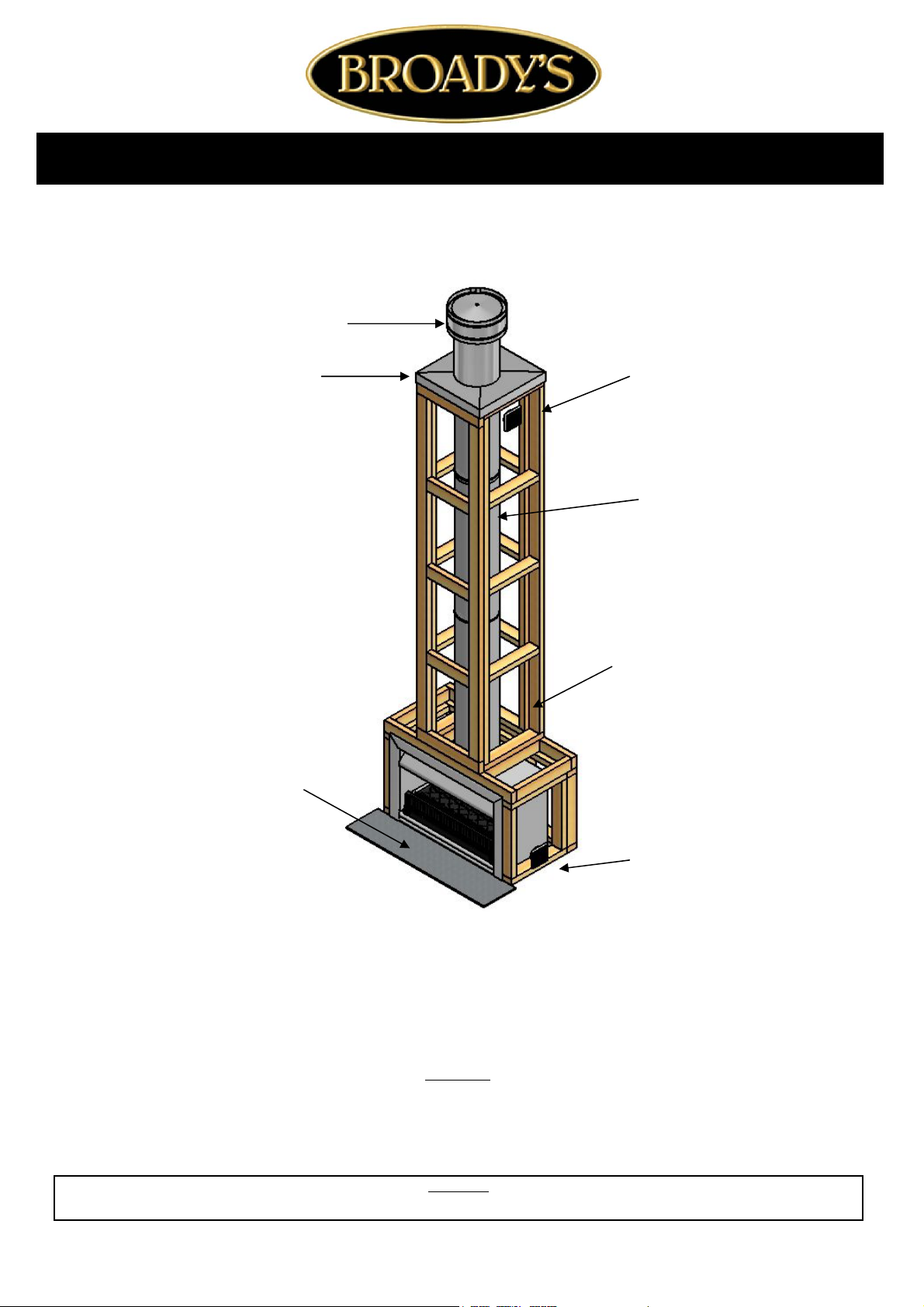
Warmington Gas Cowl
S/S Flashing
( Top Venting can also be
through S/S Flashing .
See Flashing Detail in Spec )
Gas Firebox
Hearth
Warm Air Outlet
Vent
Warmington Flue System
Timber Framing
Cool Air “Caitec
Vents” Inlet Vent
A Certified Craftsman Gas Fitter and Certified Electrician are required to run Power and Gas Supplies as required to the unit and any Commissioning as
1
Keep these Instructions for further reference……Ensure that you have the correct and current installation details for the Broady’s Fire
part of the Installation process . The heater must be Installed according to these Instructions and in Compliance with all relevant building , gas fitting,
Read all the instructions carefully before commencing the Installation. Failure to follow these instructions may result in a fire hazard and void the warranty
Due to continued product improvement, Broady’s reserves the right to change product specifications without prior notification.
Installation to Comply with NZS 5261 / 5262:2003
Fire, flue system and instructions to comply with NZS 5261/5262 :2003
Installation
The Broady’s unit is to be Installed by a Certified Broady’s Installer or an Approved NZHHA Installation Technician .
See www.homeheat.co.nz/members for a Certified NZHHA SFAIT Installer in your area .
electrical and other statutory regulations.
IMPORTANT
All Dimension are in mm………….Copyright ©
Page 2

14 December 2010
y
POINTS TO CONSIDER PRIOR TO INSTALLATION
Location of the Fire. Open Fires are better located at one end of a room or area, as they project the heat away from their opening .
Venting to the Cavity.
This air is to allow the Cavity to Vent the Warm Air. This Warm Air helps keep the Fire and Flue System form getting to Cold . If the Flue and Fire get to Cold the System
may soot often and require cleaning. Each Fire has different ways of venting the cavity .
The Topography of the Land .
The slope and position of the Land in relation to the Home has a bearing on how the wind will interact with the Fire and Flue System. Care needs to be taken to ensure
that the Flue Termination is in the correct position to maximise performance .
The Prevailing Wind.
Care needs to be taken to ensure that the Flue Termination is in the correct position as wind and gusts that hits the Flue and Cowl System may overcome the Cowl and
draft back down the Flue into the Home. This can be a combination of down draft and high pressure.
Hearth and Plinth:
The height of the Hearth off the Floor. The Finishing that is to be used on the hearth is to be allowed for at the design stage.
Positioning of the Flue System:
There is a maximum distance that an Offset Flue can be Installed. Reference to AS/NZS : 2918 , NZS 5261:2003
Flue and Fire Clearance:
To be maintained to the Manufactures Instructions.
Pressure Differential, Venting & External Air into the Building :
All fires need air to burn and draw correctly, Kitchen Fans, Air Conditioning units, High Wind Zones, Naturally forming Draft spaces, can all have an effect on the
pressure difference from inside the building to the outside. A lower pressure in the building may induce a draft down the flue system and back into the building
causing the fire to smoke or spill into the building. Care needs to be taken at the design and installation stage to adequately vent the building, or some mechani-
cal system to ensure that there is always a neutral or positive pressure at the fireplace and a negative pressure at the flue outlet. This will ensure that the draft in
the flue system is always to the outside.
“CAITEC AIR” the limits and requirements. See details in these Spec’s or contact your local Agent.
Wind Noise:
You may encounter wind noise in some installations. It is recommended to use an enclosed chase with a chimney pot to help reduce noise.
There will always be some noise from the flue systems of all fireplaces.
INSTALLATION ORDER OF OPERATIONS
Prior to Construction and Installation Important Notes:
1. Consult a Certified Craftsman Gas Fitter for correct Gas Installation.
2. Install to NZS 5261: 2003 (or current standard).
3. Install to manufacture’s specifications.
4. All New Installations require a permit.
5. Allow for gas supply to heat cell at R.H. rear, and power supply to L.H. rear if required (check product).
6. For special requirements concerning materials (Timber Mantle and Surrounds) within close proximity of Broady`s products, please contact
Technical Consultant .
7.
Stage 1: Frame Construction Procedure by Builder.
1. Mark out Flue Centre.
2. Mark out Heat Cell Clearance requirements.
3. Build Timber Framing to Heat Cell Clearances and Chimney Chase Clearance requirements.
4. Ensure that the front face of Heat Cell Clearance alcove is left open and unframed to enable Installation of the Firebox. The Chimney Chase is left unlined for Installation of the Flue.
5. Construct Plinth only, to required height. *
Stage 2: Install Procedure by Certified “Broadys Installer”only.
1. Fit Fire to Plinth.(Ensure Gas Supply Line is fed through R.H. Side of Firebox.)
2. Fit Flue System.
3. Fit Cowl and Flashing System.
4. Fit Vents to Heat Cell Alcove and Chimney Chase, to cool the Heat Cell and ensure efficiency of CAITEC Technology.
5.
Stage 3: Finishing Procedure by Builder.
1. Construct Hearth to required thickness. *
2. Finish Framing of Heat Cell Alcove.
3. Close in Heat Cell Alcove and Chimney Chase.
4. Finish Heat Cell Alcove and Hearth to customer’s requirements (e.g. paint / tiles).
5. * Note: Certified Installer can Install Hearth and Plinth.
Maintenance.
Visually Inspect Fireplace and Flue System.
Ensure that Firebox is operated according to the Manufacture’s Instructions.
our local Broady`s
2
Due to continued product improvement, Broady’s reserves the right to change product specifications without prior notification.
All Dimension are in mm………….Copyright ©
Page 3
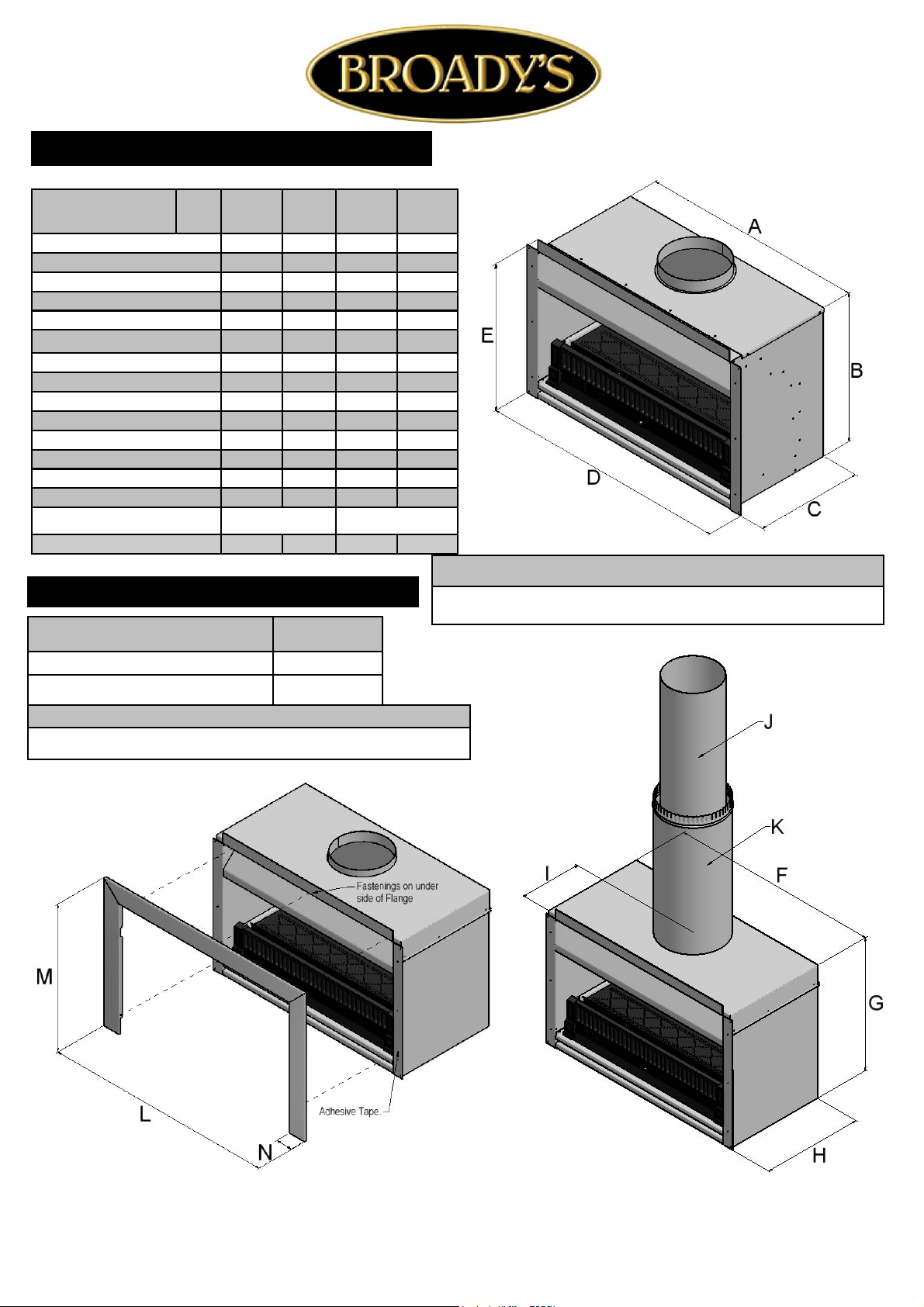
FIREBOX DIMENSION
14 December 2010
Firebox Fp
700
Firebox Width A 710 790 910 1110
Firebox Height B 600 600 600 600
Firebox Depth C 440 440 440 440
Flange Width D 800 880 1000 1200
Flange Height E 650 650 650 650
Insulation Kit Width F
Insulation Kit Height G 630 630 630 630
Insulation Kit Depth H 485 485 485 485
Centre of Flue I 315 315 285 285
Flue J 200 200 250 250
Flue Liner K 250 250 300 300
Fascia Width L 860 940 1060 1260
Fascia Height M 680 680 680 680
Fascia Section
Heat Output
Range* 6-7 7-8 8-9 9
*Estimated unless stated otherwise.
FIREBOX HEAT CELL CABINET
Minimum Flue Height
N
kW
795 875 995 1195
80 80 80 80
Fp
780
Fp
900
1100
Fp
Note:
DO NOT FRAME OUT TO THESE DIMENSIONS CHECK HEAT CELL
ALCOVE ON PAGE 5 & 6.
Flue Height 3600
Measured From Top of Firebox B + 3600
Seismec Restraint
Secure firebox through anchor positions provided, (Through base of fire).
3
Due to continued product improvement, Broady’s reserves the right to change product specifications without prior notification.
All Dimension are in mm………….Copyright ©
Page 4
14 December 2010
IMPORTANT NOTES :
GAS SPECIFICATIONS Tested to : AS 4558
NOTE : All Test Pressures are tested by an Independent Test Lab * Inlet Pressure not to exceed 4.0KPa
MODLE Fp 700 Fp 780 Fp 900 Fp 1100
LPG
Nominal Pressure kPa 2.75 kPa 2.75 kPa 2.75 kPa 2.75 kPa
Nominal Injector Size mm
Burner Pressure High kPa 2.5 2.5 2.5 2.5
Burner Pressure Low kPa
MJ/h
Falme Effect Output Only Effect Effect Effect Effect
Supply Pipe Size dia—min
Natural Gas
Nominal Pressure kPa 1.5 kPa 1.5 kPa 1.5 kPa 2 kPa
Nominal Injector Size mm
Burner Pressure High kPa
Burner Pressure Low kPa
MJ/h
35 41 48 60
Flame Effect Output Only Effect Effect Effect Effect
Supply Pipe Size dia—min 3/8” 1/2” 1/2” 5/8”
2 X 1.1mm 2 X 1.2mm 2 X 1.3mm 2 X 1.4mm
0.75 0.75 0.75 0.75
29 38 42 50
3/8” 3/8” 3/8” 1/2”
2 X 1.8mm 2 X 2mm 2 X 2.2mm 2 X 2.4mm
1 1 1 1
0.3 0.3 0.3 0.3
Lab. Test No GL 923 GL 900 GL 834 GL 876
Lab. Test Dates
ESS Declaration No: 1149420106 1149520106 1149720106 1149820106
SEISMIC RESTRIANTS
Seismic Restraint
Secure Firebox through
anchor points provided
20/04/2010 26/02/10 26/06/09 24/12/09
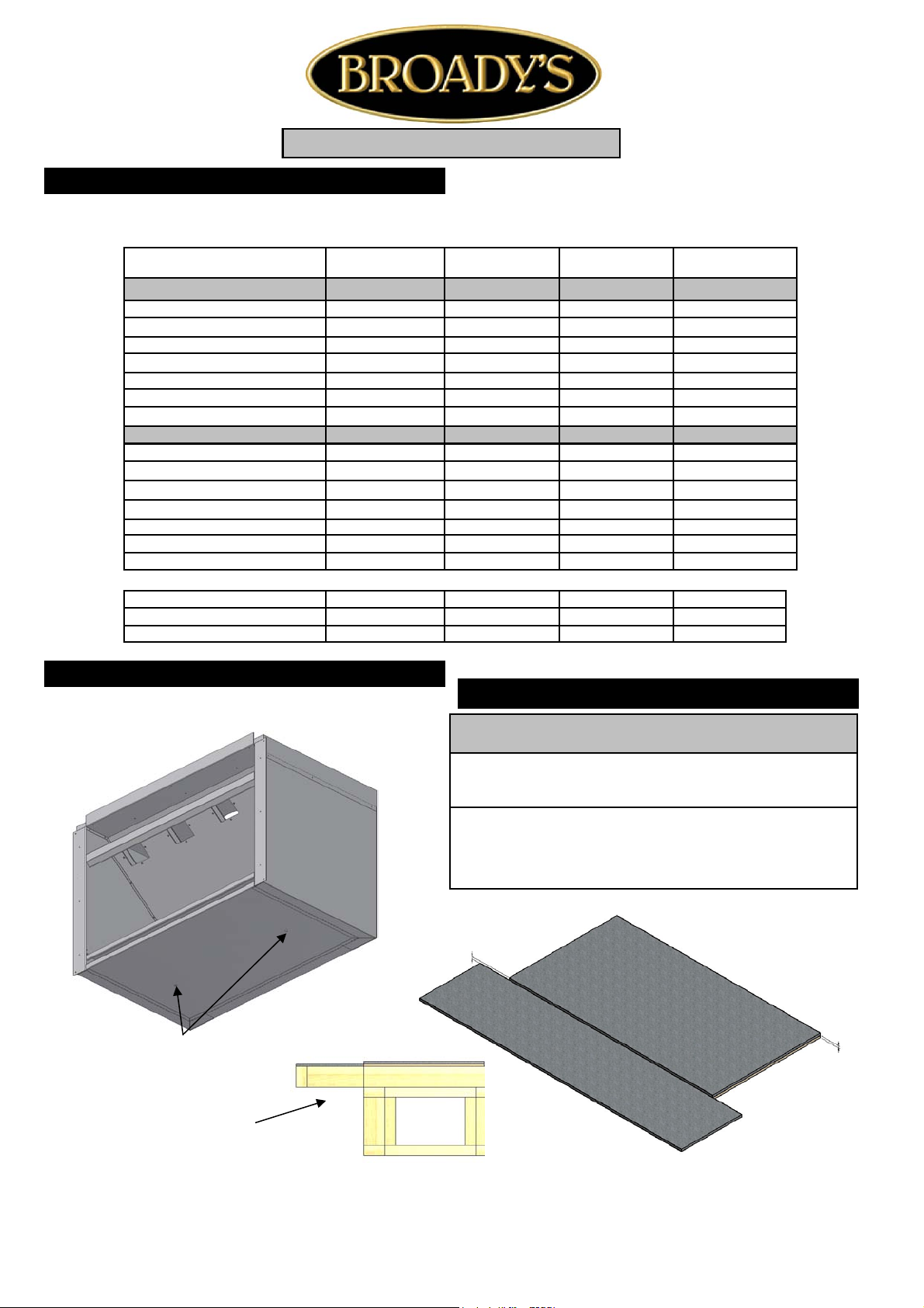
HEARTH & PLINTH CONSTRUCTION DETAILS
Note: Hearth and Plinth Construction.
Plinth to be Offset above Hearth by the Hearth Finishing’s
( e.g. Tiles / Granite / Solid Plaster / etc )
Raised Hearth’s & Plinth’s with Canter Levered Hearth’s
must be adequately supported to take the weight in Accordance with the NZ Building Code .
Offset for
Hearth
finishing
Offset
This is a Raised & Canter Levered
Hearth. See page 15 for further
Raised Hearth Detail
*Note: If Solid Plastering the Heat Cell Structure, it is recommended to use a Fibreglass Mesh with a Latex Based Plaster to
minimise the chance of the Solid Plaster cracking. (See your Solid Plasterer for correct materials and applications).
4
Due to continued product improvement, Broady’s reserves the right to change product specifications without prior notification.
All Dimension are in mm………….Copyright ©
Page 5
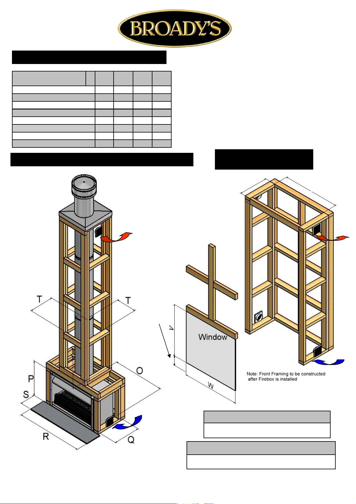
TIMBER FRAMING & TRIM OUT DETAILS
Firebox
Heat cell Clearance Width O
Heat Cell Clearance Height P
Heat Cell Clearance Depth Q
Hearth Width R
Hearth Projection S
Chimney Chase Clearance
Window Height V
Window Width W
T
Fp
700
810 895 1010 1210
660 660 660 660
535 535 535 535
1100 1180 1300 1500
300 300 300 300
350 350 400 400
660 660 660 660
810 895 1010 1210
Fp
780
Fp
900
14 December 2010
Fp
1100
MINIMUM HEAT CELL ALCOVE CLEARANCES & FRAME OUT
Warm Air Vent
Window
Height ‘V’
must be
measured
from top of
Hearth .
COMMON ALCOVE FRAMED
OUT TO 2.4 MTR HIGH
Q
O
Standard
2400mm Stud
5
Hearth Height
Cool Air external
Intake Vent
Note:
Centre Line of Flue is `NOT’ in Centre of
Alcove
Note:
All Framing Dimensions are Internal Only
Due to continued product improvement, Broady’s reserves the right to change product specifications without prior notification.
All Dimension are in mm………….Copyright ©
Page 6
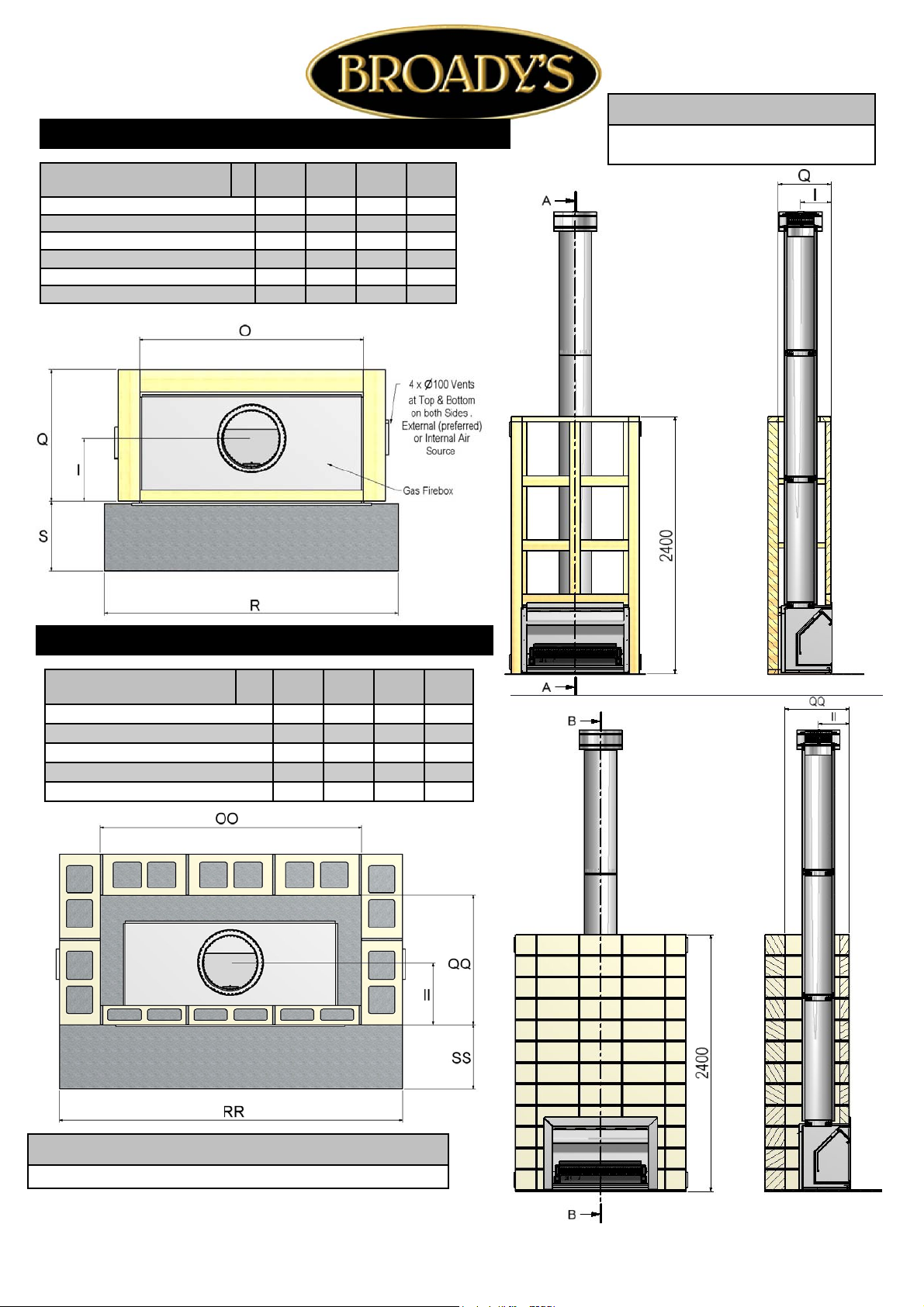
TIMBER : PLAN, FRONT ELEVATION & CROSS SECTION
Firebox
Hearth Width R 1100 1180 1300 1500
Hearth Projection S 300 300 300 300
Alcove Width O 810 895 1010 1210
Alcove Depth Q
Centre of Flue I 315 315 285 285
Chimney Chase Clearance T 350 350 400 400
Fp
700
535 535 535 535
Fp
780
Fp
900
Fp
1100
14 December 2010
Note:
Centre Line of Flue is `NOT’ in Centre of Alcove
BLOCK : PLAN, FRONT ELEVATION & CROSS SECTION
Firebox
Plinth Width
Plinth Depth
Hearth Width
Hearth Projection
Centre of Flue
Fp
700
OO
810 1210 1210 1210
QQ
600 600 600 600
RR
1100 1180 1300 1500
SS
300 300 300 300
II
315 315 285 285
Fp
780
Fp
900
Fp
1100
Note:
Centre Line of Flue is `NOT’ in Centre of Alcove
6
Due to continued product improvement, Broady’s reserves the right to change product specifications without prior notification.
All Dimension are in mm………….Copyright ©
Page 7
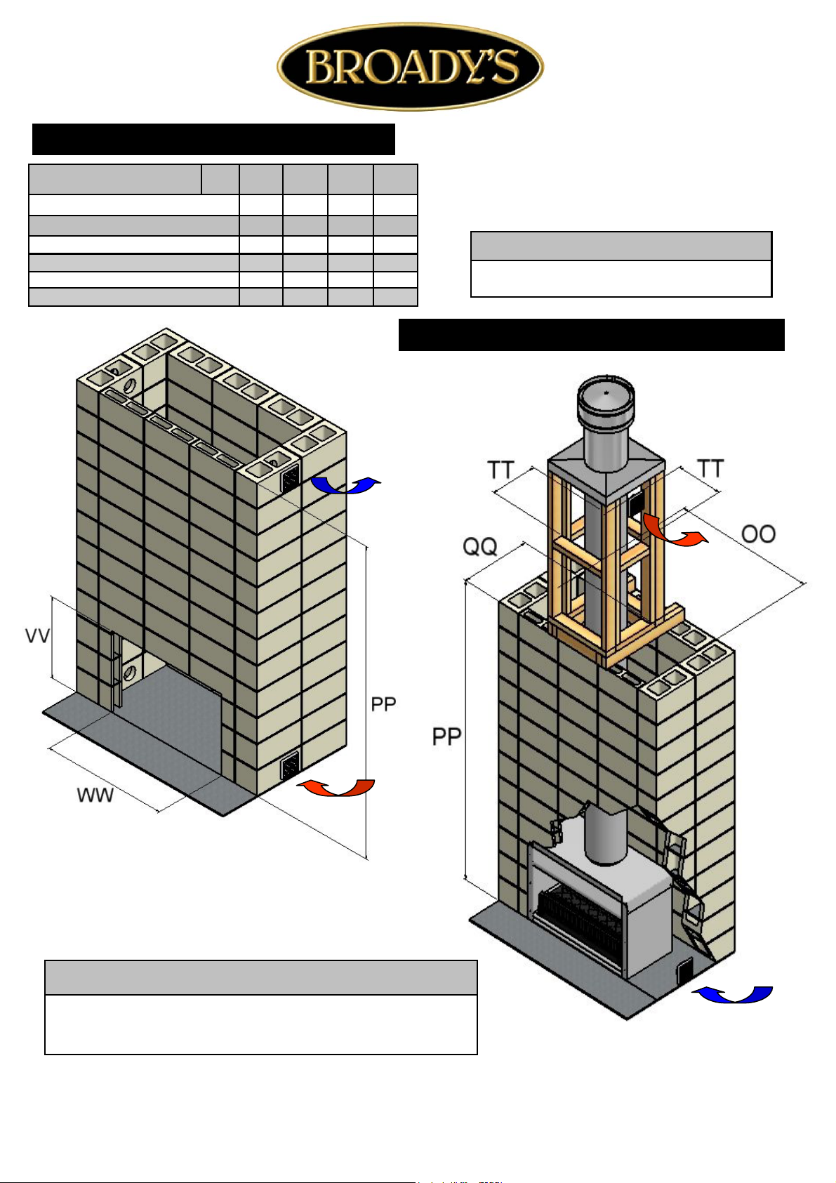
BLOCK ALCOVE & TRIM OUT DETAILS
14 December 2010
Firebox
Heat cell Clearance Width OO
Alcove Clearance Height PP
Alcove Clearance Depth QQ
Window Height VV
Window Width WW 800 880 1000 1200
Chimney Chase Clearance TT
Fp
700
810 1210 1210 1210
2400 2400 2400 2400
600 600 600 600
630 630 630 630
350 350 400 400
Fp
780
Fp
900
Fp
1100
Warm Air Vent
Note:
Centre Line of Flue is `NOT’ in Centre of the
Chimney Chase
MINIMUM HEAT CELL BLOCK ALCOVE CLEARANCES
Warm Air Vent
Cool Air
external
Intake
Vent
Note:
Ensure that the Fire and Flue System is Installed before the alcove
access is blocked off .
Block modules may vary to the drawing . (See Blocklayer)
7
Due to continued product improvement, Broady’s reserves the right to change product specifications without prior notification.
All Dimension are in mm………….Copyright ©
Cool Air
external
Intake
Vent
Page 8
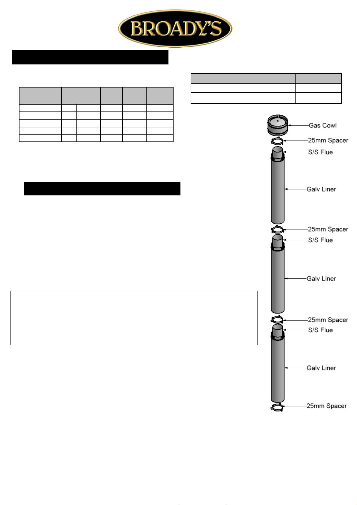
FLUE DETAILS DIMENSIONS
y
Minimum Flue Height
Flue details
Cowl 1
Flue Diameter 3
Liner Diameter 3
Spacer 3
Bottom Spacer
NOTE:
No:
Fp
700
Fp
780
Fp
900
200 200 250 250
200 200 250 250
250 250 300 300
200/250 200/250 250/300 250/300
200/250 200/250 250/300 250/300
1
Fp
1100
Flue Height 3600
Measured From Top of Adaptor B + 3600
Ensure that a Standard Tested Broady’s Flue System is used on the Broady’s Fires.
FLUE SYSTEM INSTALLATION GUIDE
14 December 2010
This is a general installation guide only – Contact a “NZHHA Installer” or Gas Fitter for
Installation Advice.
1. Install the first length of flue pipe with the crimped end down, inside the Adaptor collar, ensure that the
flue pipe is sealed into the collar with exhaust sealant. Rivet the flue in 3 places around the Adaptor collar.
Place a bottom spacer around the flue pipe approximitaly150mm above the adaptor collar. Secure in position by tightening the screw and nut.
2. Install the second length of flue pipe with the crimped end down and fit by riveting in at least 3 places
around the flue pipe joint. Ensure that the flue is sealed into position with sealant.
3. Install the first section of flue pipe liner with the Crimped end up, over the flue pipe and over the spacer
that is fixed to the flue pipe. This spacer will keep the liner concentric about the flue pipe.
4. Position flue spacer at the flue pipe joint for every length of “Flue pipe” and “Liner”.
Repeat the Steps from 1 – 4 to the installed required height of the flue system. The flue system is to comply with
ASNZS 2918:2001 4.9.1 & NZS 5261/5262:2003
• a “the flue pipe shall extend not less than 4.6m above the top of the floor protector.”
• b “ the minimum height of the flue system within 3 m distance from the highest point of the roof shall be 600mm
above that point.”
• c “the minimum height of the flue system further than 3 m from the highest point of the roof shall be 1000mm
above the roof penetration.”
• d “no part of any building lies in or above a circular area described by a horizontal radius of 3 m about the flue
s
stem exit.”
IF FLASHING CONE NEEDED
1. NOTE: The last length of flue pipe needs to extend past the liner so that when the “top spider” and the “Flashing cone”
are fitted, that the “flashing cone” and the “flue pipe” are flush, or that the “flue pipe” is 5mm lower that the “Flashing
cone”.
2. Fit the “Top Spider” into position, ensure that the legs of the spider are fitted inside the liner and that the spider is
positioned hard down onto the liner and tighten with the screw and nut.
3. Place the “Flashing cone” over the “flue pipe” and press hard down onto the “Top Spider”. (Note that the “Flue pipe”
and the “Flashing Cone” are either flush or the “Flue pipe” is 5mm Lower than the “Flashing cone”.) Ensure that the
“Flashing cone” is clear for the venting from the “Liner” and the “flue pipe”.
4. Fit the “Cowl” to the top of the flue pipe. The “Cowl”, “Flashing cone”, and the “Flue pipe” can be secured to each
other with the uses of a stainless steel self tapping screw. This will allow the “Cowl” to be removed for cleaning.
5. Flue system may require Bird Proofing due to the installation and locations, discuss this with your installer for the best
advice.
6. If the Flue system is installed into a “Chimney Chase”, allow for air vent as close to the top of the chase as practical, or
allow venting through the “Chimney Chase Flashing”. A “Venting Flashing cone” and a 25mm gap around the Liner
with a “Venting Flashing Cone-Spider” can be used. Ref : to Figures ……in this specification.
8
Due to continued product improvement, Broady’s reserves the right to change product specifications without prior notification.
All Dimension are in mm………….Copyright ©
Page 9
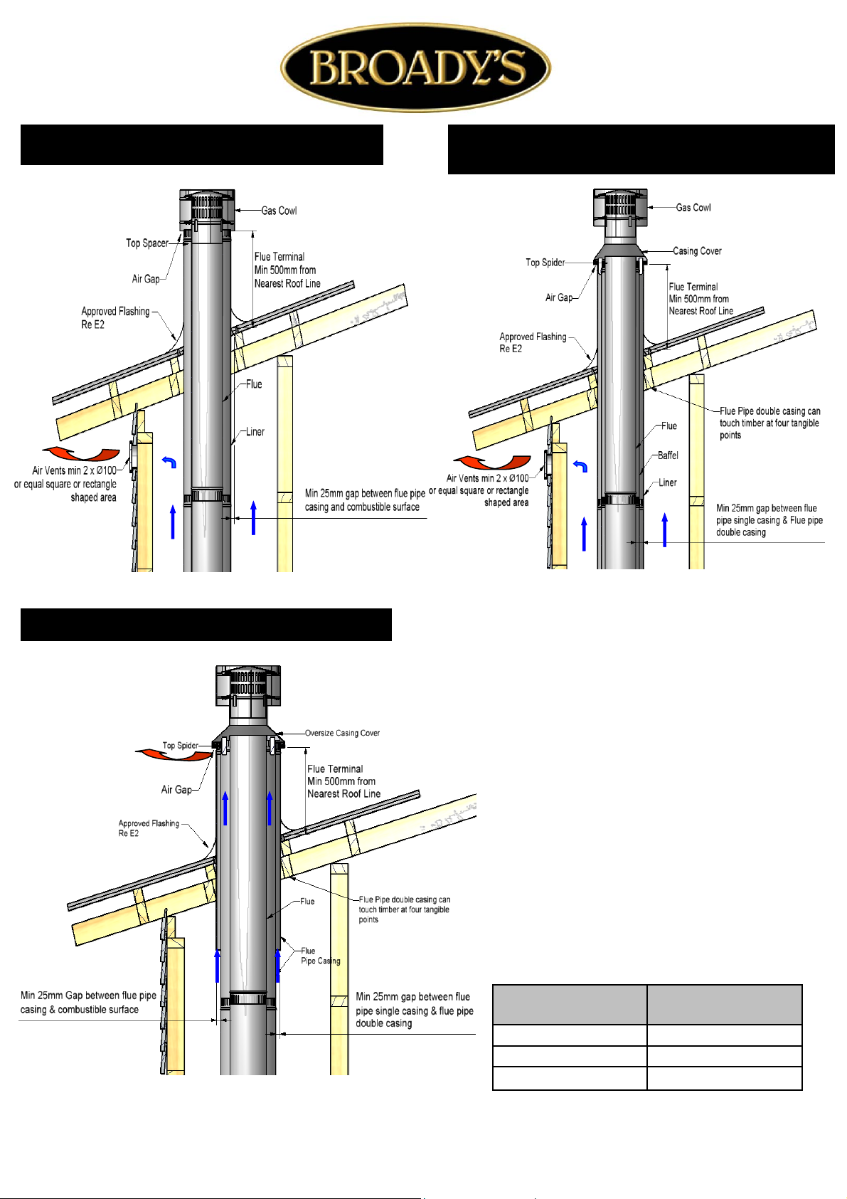
14 December 2010
FLUE PENETRATION Vented through Alcove (Single
lined Flue System)
FLUE PENETRATION Vented through Alcove (Double
lined Flue System)
FLUE PENETRATION Vented through Top Flashing
Note :
External Requirements
Refer to AS/NZS2918:2001 4.9.1/
NZS5261/5262:2003
Install Flue system to AS/NZS2918:2001/
5261/5262:2003
When using a rubber or Bitumen flashing (Butynol,
Dectite) an Additional Flue pipe Baffle is required.
All external air vents & ceiling penetrations must
be bird proofed with permanently fixed screens.
All flashing to comply with E2.
All external air vents and ceiling penetrations are to
be Vermin and Rodent proof.
Test Report Number Date of Report
9
04/1039 20th July 2004
04/1040 20th July 2004
04/1041 20th July 2004
Due to continued product improvement, Broady’s reserves the right to change product specifications without prior notification.
All Dimension are in mm………….Copyright ©
Page 10
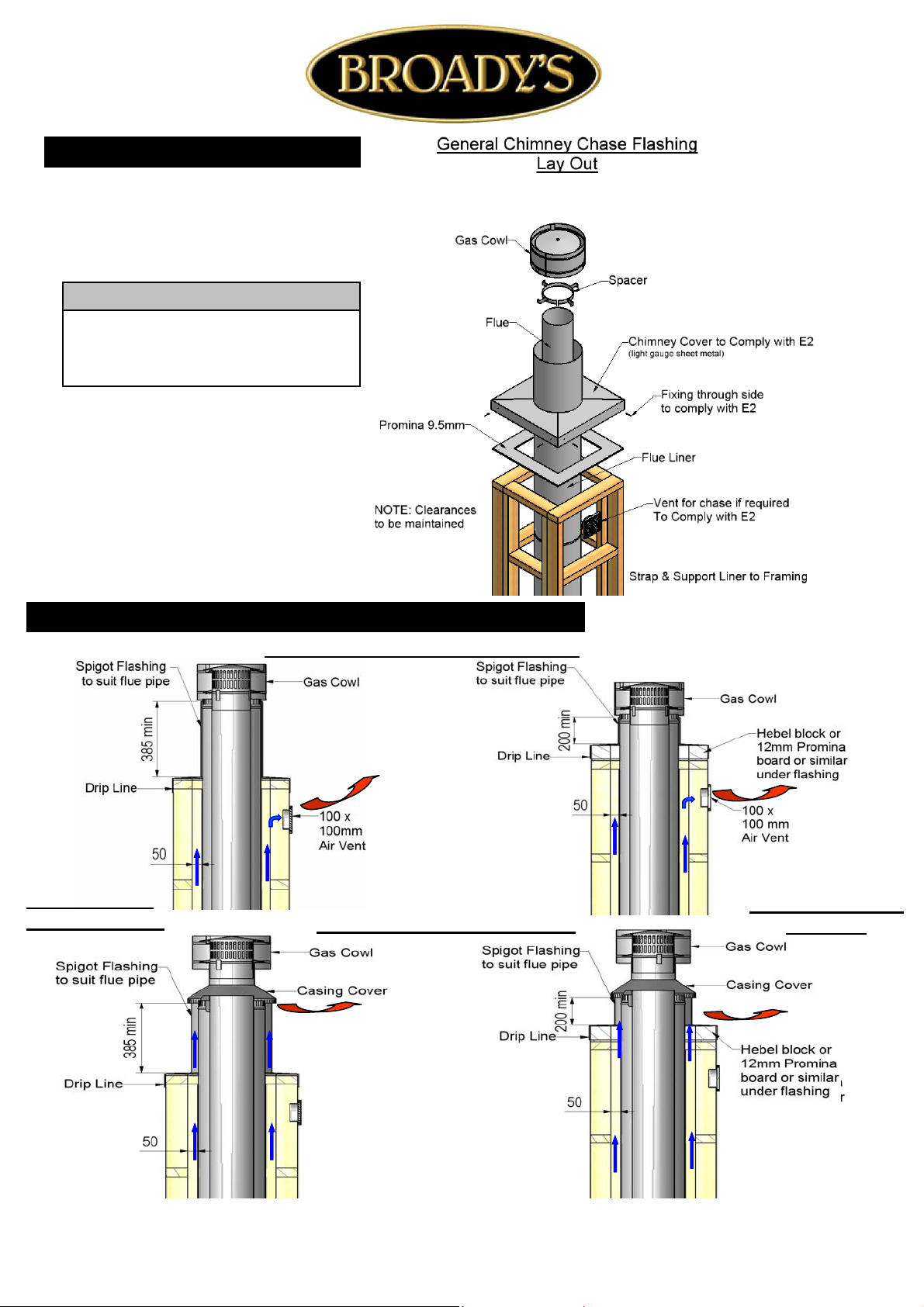
CHIMNEY CHASE FLASHING DETAILS
Note:
Flashing Spigot height is determined by
the Insulation that is fitted under the
Flashing … See Details at bottom of page.
14 December 2010
“CHIMNEY CHASE FLASHING” AND “AIR VENTILATION” OPTIONS :
VENTING THROUGH CHIMNEY CHASE
“No Insulation
under flashing”
VENTING THROUGH FLASHING
“Insulation under
flashing”
10
Due to continued product improvement, Broady’s reserves the right to change product specifications without prior notification.
All Dimension are in mm………….Copyright ©
Page 11
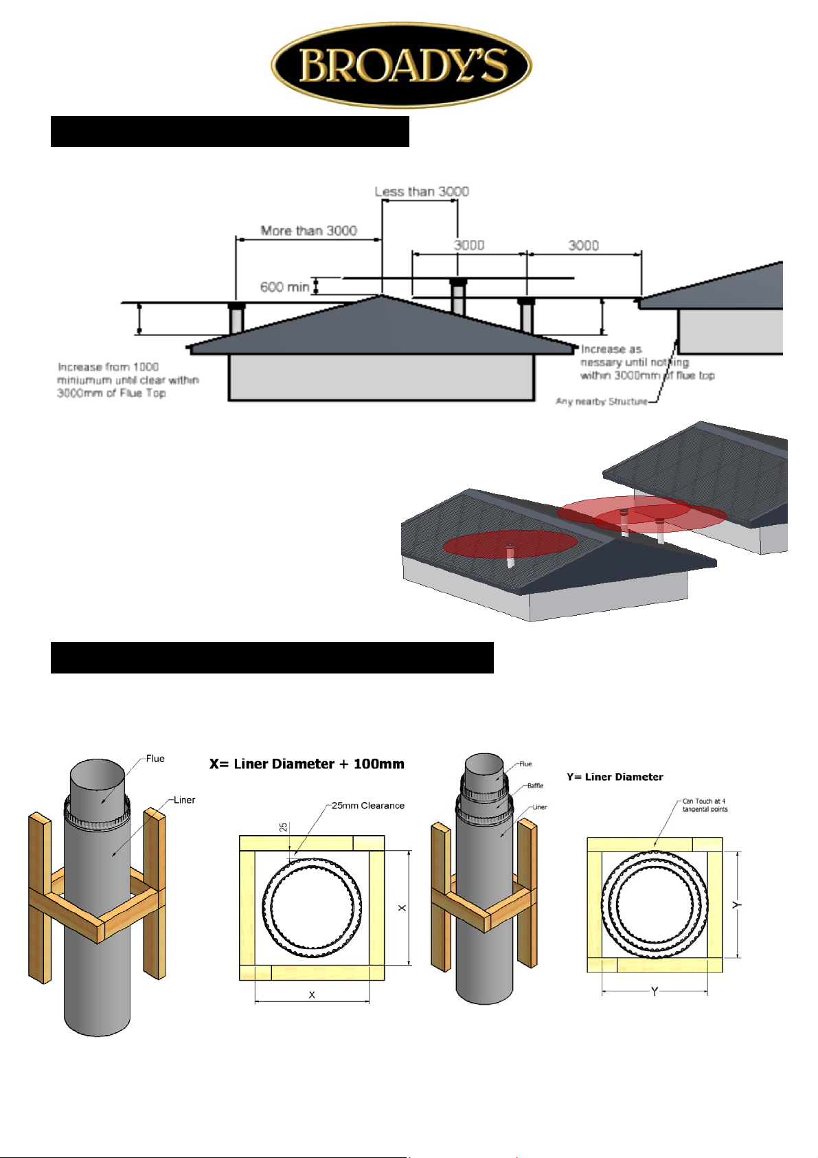
FLUE HEIGHT MINIMUM DETAILS
14 December 2010
The Flue exit is to comply to ASNZS 2918 : 2001
3D View
FRAME OUT AND TRIM OUT DETAILS FOR CHIMNEY CHASE
Option X – Singled Lined Flue System Option Y – Double Lined Flue System
11
Due to continued product improvement, Broady’s reserves the right to change product specifications without prior notification.
All Dimension are in mm………….Copyright ©
Page 12
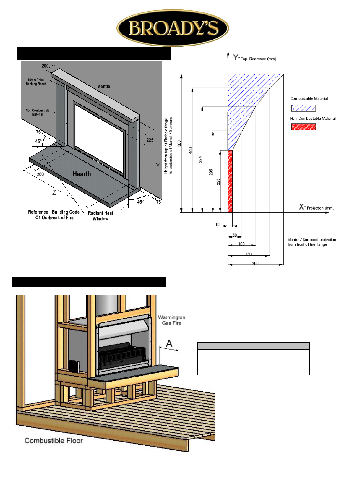
COMBUSTIBLE MANTLE CLEARANCES
14 December 2010
HEARTH CLEARANCES
Note: For Combustible Floors
Minimum Hearth of 300mm (A) must be
maintained at any given height.
12
Due to continued product improvement, Broady’s reserves the right to change product specifications without prior notification.
All Dimension are in mm………….Copyright ©
Page 13
14 December 2010
Fp SG & Fp EG Range: Gas Convection Fireplaces
TO THE INSTALLER / GAS FITTER and ELECTRICIAN
NOTES :
• Service annually or more if required.
• Custom built to clients requirements to NZS5261/5262:2003 Clause B2.3
• The Appliance and Flue System must be installed in accordance with NZS5261/5262:2003 and the appropriate Building codes.
• The Appliance and Flue System must be tested in accordance with NZS:5261 and the appropriate Building codes.
FLUED GAS APPLIANCES All Gas Fires requiring Tested Flue Systems shall be Installed to the requirements of NZS 5261 and shall be appropriately designed and
constructed to permit safe and effective use. This Appliance must be flued to the outside atmosphere. All Broady`s Fires must be Installed with a minimum
Approved Broady`s Gas Flue and Liners .
GAS TYPE All Gas Fires shall operate safely on the Gas Type specified on the Appliance and shall comply with the requirements of The Gas Act 1992 .
APPLIANCE SAFETY Any Gas Fire Appliance shall comply with the safety requirements of NZS 5262 or any one of the Standards listed or referred to in "related
documents" of this Standard .
ELECTRICAL REQUIREMENTS All Gas Fire Appliances Installed with Mains Supplied Electrical components for associated use with these Appliances, must comply
with The Electricity Regulations 1993.
ELECTRONIC CONTROL SYSTEMS Any Gas Fire Appliance Installed with Manual or Programmable Electronic Control System shall be tested and/or approved by
a Recognised Person or Authority.
of 3.6m of
SEISMIC RESTRAINTS All Fires used for Domestic and Commercial Purposes shall be firmly secured (unless defined as portable or mobile) to prevent dislodgement
from their point of fixture or Installation during Seismic Activity. Such Restraint must be of a reasonable expectation .
GAS CONNECTION
A Gas Certificate must be obtained for the Installation and Commissioning of this Appliance and Flue System .
Check that the Gas Type Specified on the Data Plate is correct for the available supply (LPG or NG).
A Copper Gas supply capable of supplying the correct MJ/h , should be brought into the rear of the Installation Cavity through the hole provided . A Flare Nut is provided on the Burner for Gas Connection to the Appliance .
COMMISSIONING AND TESTING OF FIREPLACE (To be carried out by Gasfitter)
Read all the instructions before commissioning. Install coals and logs and burner before commission.
Light appliance and check HIGH/LOW settings. Check operation of appliance and adjust to suit.
Adjust control valve setting if required. After a period of running (30min Plus) check the setting of the pilot and adjust if required. See Spec’s for details.
Extinguish appliance, remove test equipment and secure test nipple. Check for Gas Leaks.
Note* The Control Valves are factory set and should not require adjustment.
GAS FITTER TO CARRY OUT STANDARD TESTING FOR COMMISSION:
•
Spill test taken at top of opening with smoke or smoke match,
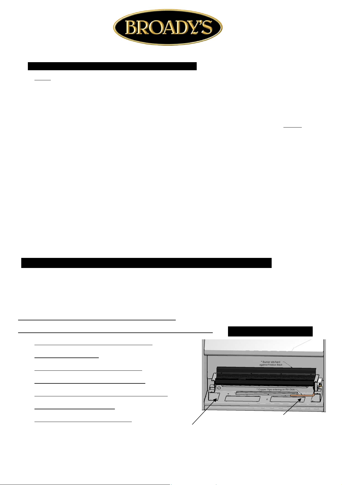
FITMENT OF BURNER
• Leak testing appliance and joints,
• Correct operation of the burner and coal and log lay out,
• Test gas pressures high and low, drop test on supply line,
• 5 second light time across burner, Other testing that may be required.
• Ventilation requirements to the standards,
• Hand over to Client, tests and comply to NZS:5261.
13
Due to continued product improvement, Broady’s reserves the right to change product specifications without prior notification.
All Dimension are in mm………….Copyright ©
Burner may be
To the Firebox
Secured
(Optional)
Gas Supply Pipe
Into Fire ,
by Gasfitter .
See Spec’s for
Pipe Size.
Page 14
14 December 2010
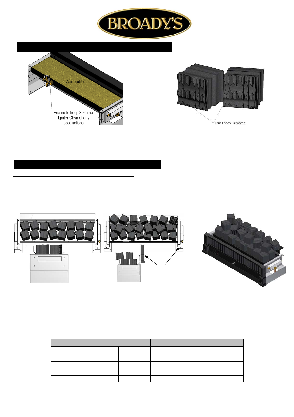
VERMICULITE (COURSE) (To be set by Gasfitter)
General Coal orientation fro optimum effect.
APPLYING THE VERMICULITE : (Course—must be larger than the burner plates holes so not to block them)
Apply with care a thin layer of Vermiculite over the Burner, just enough to cover the Burner Tray only .
NOTE: If the burner flame is uneven, the Vermiculite may need to be changed or sifted to remove the smaller pieces that can block the burners
holes. The smaller pieces can ,cause uneven burn and the unit to run dirty.
COALS AND LOGS (To be set by Gasfitter)
Gloves should be worn when handling Ceramic Fibre Coals & Logs : care needs to be taken when handling Coals & Logs , Due to the Carbon on the
Coals can stain the surroundings.
HELPFUL HINTS : When Hot use Metal Tongs.
Apply a thin layer of Vermiculite over the Burner , just enough to cover the Burner Tray only as shown above.
1 : Bottom Row : Assemble 2 Bottom Rows of Coals onto the Vermiculite Base . 2 : Top Row : Assemble 2 Top Rows of Coals onto the Bottom Row .
1 : Bottom Row
Each Coal randomly positioned with the Torn (roughest) Face Outward . Ensure Coal positioning does not directly block the 3 Flame Pilot .
The placement of the Coals & Logs may vary to make an even Flame Pattern .
2 : Top Row
Slide R & LH Grate
Pins into Holes located
on the Burner Side
plates .
Model SG780 Shown: Total number of coals will vary per model.
Logs and Twigs may be scattered to achieve best Visual Effect .
Fit Burner Grate by sliding R & L Side Metal Pins on Grate, into Holes Located on Burner Side Plates , as shown below .
14
Model
Fp 700
Fp 780
Fp 900
Fp 1100
Due to continued product improvement, Broady’s reserves the right to change product specifications without prior notification.
Number of Coals per Row Number of Rows
Bottom Top
6 5 2 2
8 6
10 9 2 2
11 10 2 2
All Dimension are in mm………….Copyright ©
Bottom
2
Top
2
Total Coals
Total
22
28
38
42
Page 15
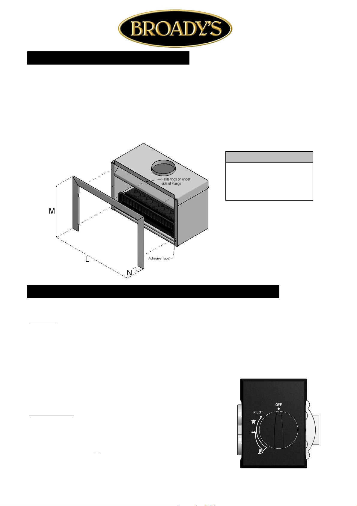
FASCIA KIT (Black or Stainless Steel)
Locate the three self-tapping screws provided into the under-side of the top ledge of the firebox
Remove the backing tape from the adhesive Velcro pads at the bottom of each fascia side
Offer the fascia into position locating the three screws into their associated slots - tighten screws
Apply firm pressure to the bottom edges to bond the Velcro tape
The fascia may be removed at any time by loosening the screws and parting the Velcro
Please refer to additional sheet for Burner Ratings and Frame-out details.
Note:
Fascia is Fitted at the end of the
Installation process and may be
after the wall and surroundings
have been completed .
14 December 2010
OPERATION OF YOUR GAS CONVECTION FIRE (Manual ONLY)
Your Fire must be Installed and Tested by a suitably qualified Gasfitter prior to use.
To light :
Lower the control-cover by pulling it outwards .
Depress the Ignition Switch and hold in the 'PILOT' position for 3-5 seconds. (This may take some time for the Gas to come
through to the Pilot-3 Flame)
Strike the Igniter by turning to the 'STAR' position , maintaining the Switch in a Depressed State ; (repeat steps 2 & 3 if neces-
sary)
Once the Pilot Flame is lit, hold this position for 3-5 seconds , release from the Depressed State
before setting the Flame Control to Full , it may take 3-5 seconds for the Burner to Light .
Once the Flame Bed is established, set the Flame Control to the desired level & close cover.
To shut down :
Open control cover by pulling it outwards.
Turn control switch to 'PILOT'. Flame bed will extinguish.
Pilot light may be left running or extinguished by switching to 'OFF' before closing cover.
15
Due to continued product improvement, Broady’s reserves the right to change product specifications without prior notification.
All Dimension are in mm………….Copyright ©
Page 16
14 December 2010
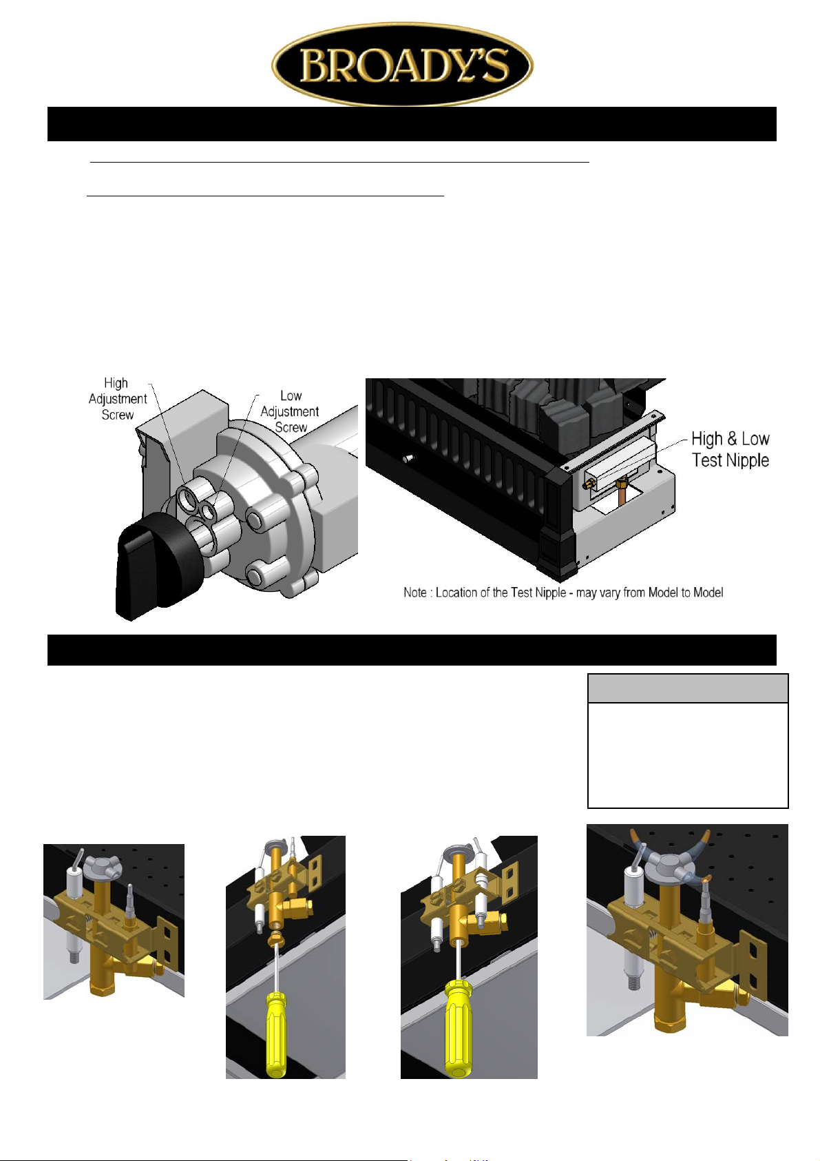
ADJUSTMENT OF HI—LOW PRESSURE (Manual ONLY) (Only to be Adjusted by Gasfitter)
Adjustment of High & Low Settings Must be Carried out by a Certified Gas Fitter Only .
Note* Control Valves are Factory Set but may require adjustment onsite .
Turn Appliance Off & Remove Front Plastic Cover on Igniter , Pull Cover to Slide off .
Unscrew Test Nipple on the Burner Manifold & fit the Test Gauge Securely - See Diagram
* To Set the High : Light the Burner & turn to High - Then Adjust the High Screw to the Desired Pressure . See Spec’s
* To Set the Low : Light the Burner & turn to Low - Then Adjust the Low Screw to the Desired Pressure . See Spec’s
Extinguish Appliance, remove Test Equipment and Secure Test Nipple .
* Check Valve & Burner for Correct Operation & check Fire for Gas Leaks .
for Gas Fires
ADJUSTMENT OF THE PILOT—3 FLAME (BOTH Fp SG & Fp EG) (Only to be Adjusted by Gasfitter)
Note: When the Base screw is removed, gas will leak from the out let, ensure that the pilot is not adjusted
or the screw is removed when the fire is burning.
• Adjustment of Pilot - 3 Flame : Unscrew Base Screw as shown in Diagram 2 .
Note: to Gas Fitters
The 3 flame pilot may need adjustment
after a period of running time on set up
as the increase in heat in the fire will
• Insert a Screw Driver as shown in Diagram 3 and adjust the Adjustment Screw up inside the 3
Flame Pilot to adjust the Flame Height .
induce a higher draft in the fire, and
may pull in flame away from the File
Tube causing the fire to shut down.
• The Flame must always be passing over the Electrodes &/or File Tube on either side .
3 2
3 Flame Pilot in
Assembled State
Correct Operation of
3 Flame Pilot
16
Due to continued product improvement, Broady’s reserves the right to change product specifications without prior notification.
All Dimension are in mm………….Copyright ©
Page 17

14 December 2010
POINTS OF SAFTEY—To the Customer /Home-Owner
Your Broady`s Gas Decorative Fire operates on the principle of dual radiant and convected heat. Therefore it is important to observe the following precautions associated
with any heating appliance or open fire.
• Do not cover or restrict the fireplace upper or lower vents in any way as this may result in a build-up of hazardous gases within the room.
• The fire is not intended for the drying of clothing, bedding etc.
• Avoid installing this appliance in high traffic areas, strong draughts or near drapes or furniture.
• The use of an approved fireguard is recommended for the protection of young children.
• Avoid using aerosols when the appliance is operating.
• Avoid anyone leaning against or lying directly in front of the fire while operating.
• Do not place anything objects into or against the gas fire at any stage.
• The fire may release a small amount of smoke on its first start up which may take 1or 2 hours to dissipate . This is part of the curing process so ensure there is
adequate ventilation within the room.
• Always use a registered Gas Fitter or Electrician for installing and maintenance work
• Always use certified gas cylinders that have been tested and are safe to use.
• Never modify your gas appliance or its settings from those specified by the manufacturer.
APPLIANCE SAFETY Any gas fire appliance shall comply with the safety requirements of NZS 5262 or any one of the Standards listed or referred to in "related documents" of this Standard.
ELECTRONIC CONTROL SYSTEMS Any gas fire appliance fitted with manual or programmable electronic control systems shall be tested and/or approved by a recognised person or authority.
WHAT DO YOU DO IF YOU SMELL GAS
Open windows and doors
Do not light any gas appliance
Do not use any electrical appliance or switches
Do not use the telephone in your home
Leave the building; shut off the domestic gas supply valve (beside your meter)
MAINTENANCE : All burner setting, Coals placement, Vermiculite is to be checked and set in accordance with
this specification by the service person/Gas fitter
*Lighting your gas fire using electronic or remote ignition systems may vary as per manufacturer instructions
Broadys recommend annual servicing of your gas fire by an approved Broadys dealer Gas Fitter.
External surfaces should be dusted with a damp, lint-free cloth when the fire is cold.
Broadys provide 12 months warranty from the date of purchase, for domestic or commercial installations
This Warranty Covers :
Replacement Parts and Labour for Gas Control Components due to Manufacturing Defects Only.
Repair or Replacement of the Burner or Firebox Components due to Manufacturing Defects Only.
Warranty cover will be considered void if the product is subject to incorrect installation, failure to operate the appliance in accordance with the
supplied instructions and specifications or is subject to damage or misuse beyond the expected conditions of normal use.
All Installations and servicing must be carried out by and approved Broady’s dealer or Gas Fitter.
17
Due to continued product improvement, Broady’s reserves the right to change product specifications without prior notification.
All Dimension are in mm………….Copyright ©
Page 18
14 December 2010
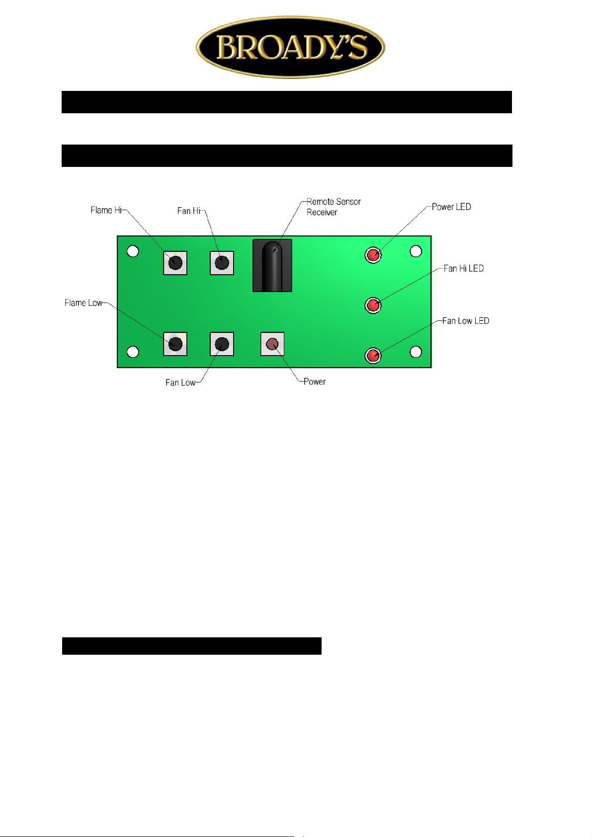
OPERATION OF YOUR FpE.G GAS BURNER IGNITER ONLY
FOR MANUAL OPERATION OF YOUR FpEG DECORATIVE FIRE
AS SHOWEN FROM THE FRONT OF THE BURNER.
This Control Panel is Located on the Bottom Left Hand Side of your decorative Gas Fire.
Press and Release the Power Button. This will Start the Electronic Spark and the Power LED will be on
Permanently . The Pilot will Ignite First, once this is on, it will ignite the Main Burner. Pressing and
Releasing the Power Button again will Switch Off the Appliance.
When the Appliance is Turned On again, the Gas Fire will resume the previous Flame and Fan settings , unless the Appliance was Switched Off due to Power Failure. In the circumstance of a Power
Failure the Remote Control System will return to the default settings which is a Low Flame and the
Fan Turned Off.
If the Gas Fails to light, the Appliance it will go into Lock Out Mode , after trying to ignite for 1 minute
(approx.) . In Lock Out Mode the Power LED will remain illuminated. To start the Appliance again
Press and Release the Power Button Twice after the Gas Supply Resumes.
FLAME OPERATION
Press and Hold the + button to Increase the Main Burner Flame . Press and Hold the - button to Decrease the Main Burner Flame. By holding the + or - Flame Button for up to 10-15 sec this will Increase
or Decrease the Main Burner Flame to it’s Max or Min .
18
Due to continued product improvement, Broady’s reserves the right to change product specifications without prior notification.
All Dimension are in mm………….Copyright ©
Page 19
14 December 2010
FAN OPERATION
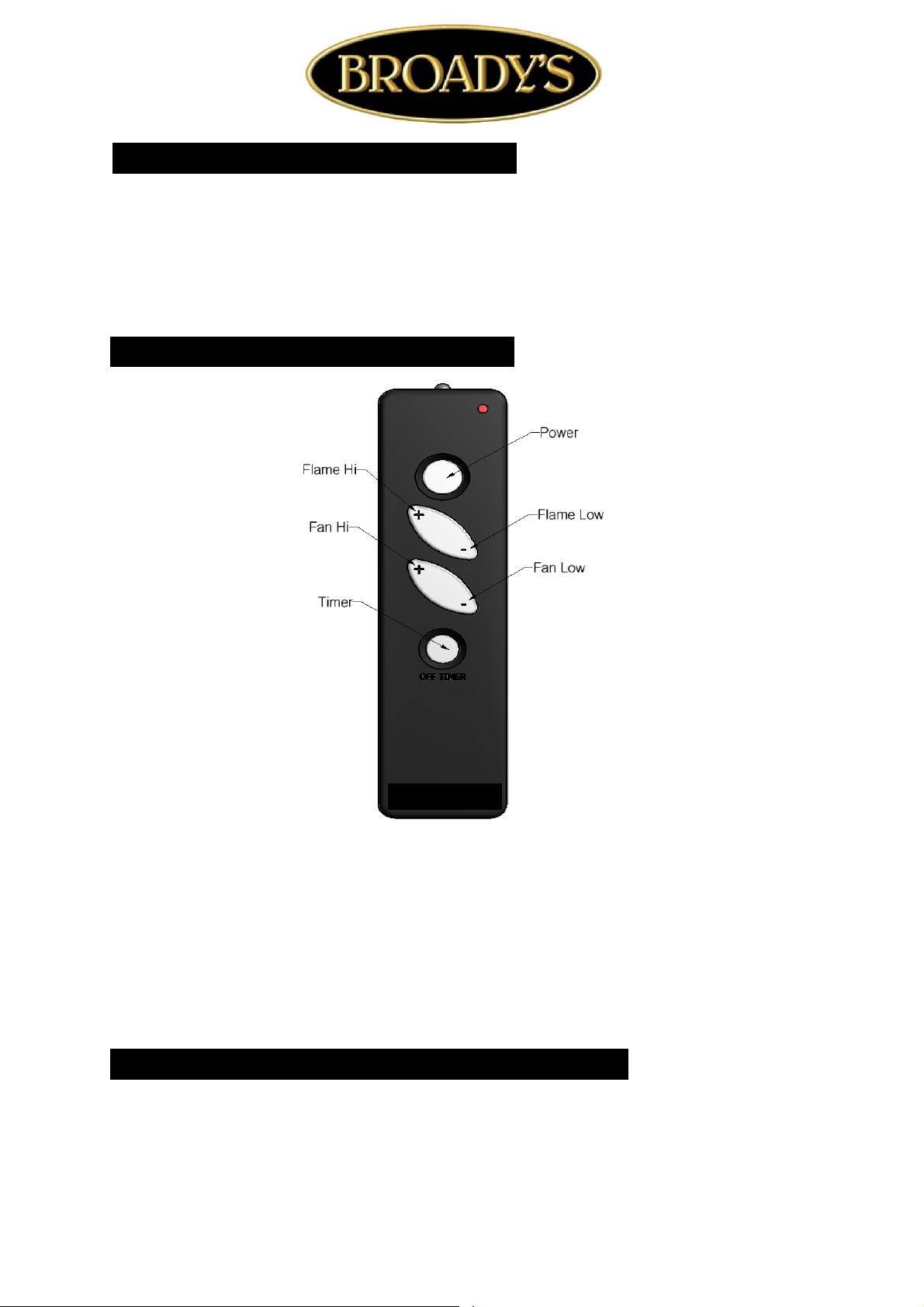
This Decorative Gas Fire has a 3 Speed Fan and its operated independent from the Main Burner.
This is done by pressing and releasing the fan + or – button will Increase or Decrease the Fan
Speed. The LED on the Front Panel will indicate the Fan Settings at Low, Medium, or High Speed.
Pressing and Releasing of the button will Lower the Speed until the Fan is Turned Off .
REMOTE CONTROL FEATURES
Your Remote Control has all the features of the Control Receiver situated on the Front Panel of the
Burner .
By pressing Timer Button , the Power LED will start flashing and after 30 minutes the appliance will
Shut Off Automatically .
By pressing the Timer Button again within the 30 minute period, this will reset the Timer and the
power LED will Stop Flashing .
IMPORTANT NOTE ABOUT YOUR DECORATIVE FIRE
Warranty Cover will be considered void if failure to operate the appliance in accordance with the
supplied Instructions and Specifications, or is subject to damage or misuse beyond the expected
conditions of normal use which could result in injury or property damage .
19
Due to continued product improvement, Broady’s reserves the right to change product specifications without prior notification.
All Dimension are in mm………….Copyright ©
Page 20
14 December 2010
PROCEDURE FOR THE TEST AND COMISSIONING OF YOUR DECORATIVE FIRE.
Ensure Gas Supply and the Power Supply (caution 240V) to the Unit.
• Refer to Data Plate on this Specification for settings. The Data Plate is attached to the under carriage of
the Burner .
• Remove Front Grate ensure the CAT5 cable to the Control Receiver is still connected.
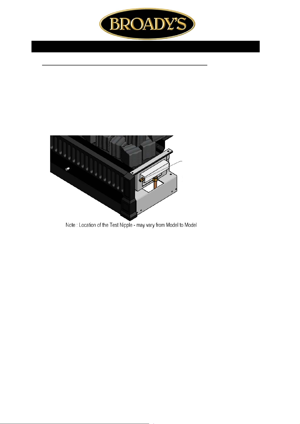
• Loosen the Jet Test point and attach manometer (Digital is preferred). The Test Point is on the Right
Hand Side of the Gas Burner , as Shown Below .
Gas Test Nipples
for SG / EG Fires
• Light Appliance, adjust to High Flame setting and check pressure, adjust to Low Flame and check pres-
sure.
NOTE : If setting the Pressure is required it is to be carried out by a Certified Gas Fitter.
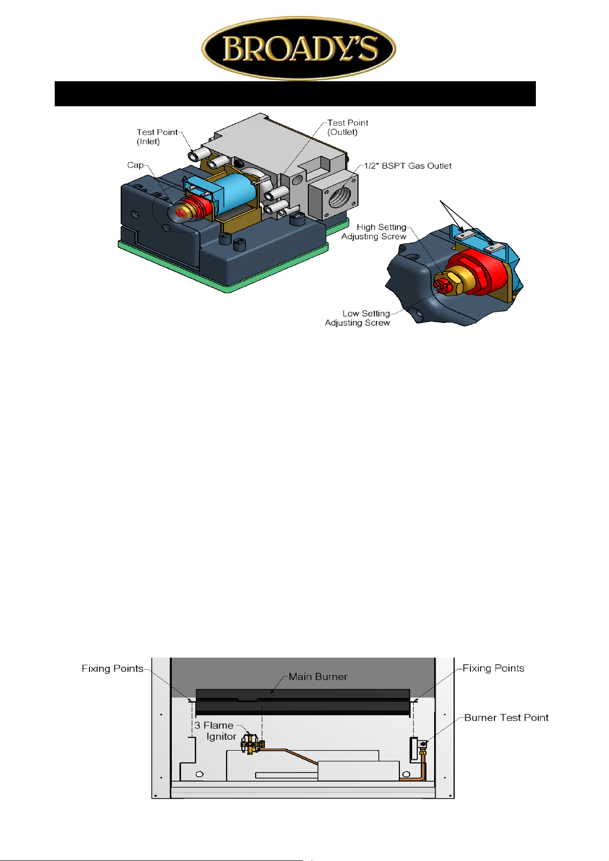
• If adjustments are necessary, remove the cap . The Pressure Adjustment Screw and Nut are on the
Front Side of the Gas Control Valve (shown in Diagram B in this specification) and are Factory set.
High Pressure Setting: Set the modulator to Maximum Condition. Screw in “Nut A” to Increase the Outlet
Pressure then screw “Nut A” out to Decrease the Pressure to the desired settings . Use 10mm spanner.
Low Pressure Setting: Turn Off the Power to the Modulator (by disconnecting the Modulator Harness Connection at the Valve - See Wiring Diagram in Page 17 .) and, keep Nut A stationary . Use a screwdriver to screw in
“Screw B” to Increase the Pressure and Screw it Out to Decrease the Pressure . Carefully replace the Modulator Plastic Cap .
WARNING: To ensure the Correct Operation of the Modulator it is necessary that the Plastic Cap is returned to
its original location .
20
Due to continued product improvement, Broady’s reserves the right to change product specifications without prior notification.
All Dimension are in mm………….Copyright ©
Page 21
14 December 2010
DIAGRAM B ( SHOWING CONTROL VALVE WITH TEST POINTS AND ADJUSTING SCREW ).
Modulator Harness Connections
Modulator Harness
Connections
“Nut A”
“Screw B”
DIAGRAM B
• After checking the pressure, turn the unit off, remove Manometer from the Test Point and Tighten the Test Point
Screw. Ensure to check for gas leaks.
• Ensure Power is Off & Reconnect Modulator Harness Connection in the Main Harness. See Diagram B Above .
• Turn the Appliance On and Off a few times to check ignition.
• When you are satisfied that the Appliance is working correctly , fit the Front Panel Assembly back to the Gas Burner.
• NOTE : Ensure you peel the Protective Plastic Coating from any Stainless Steel components if fitted.
• All Burner Aerations are Factory Preset and cannot be adjusted.
• If you are unable to get the unit to operate correctly, refer to troubleshooting before contacting your Local Service
Contact as listed.
• It may take approximately 2 hours of operation for the coals/Logs or river rocks to achieve their full flame pattern and
glow.
• During the Initial Burning in period, some smoke and smell may be experienced , the appliance should be run on the
high position in a well ventilated room until these dissipate .
21
Due to continued product improvement, Broady’s reserves the right to change product specifications without prior notification.
All Dimension are in mm………….Copyright ©
Page 22
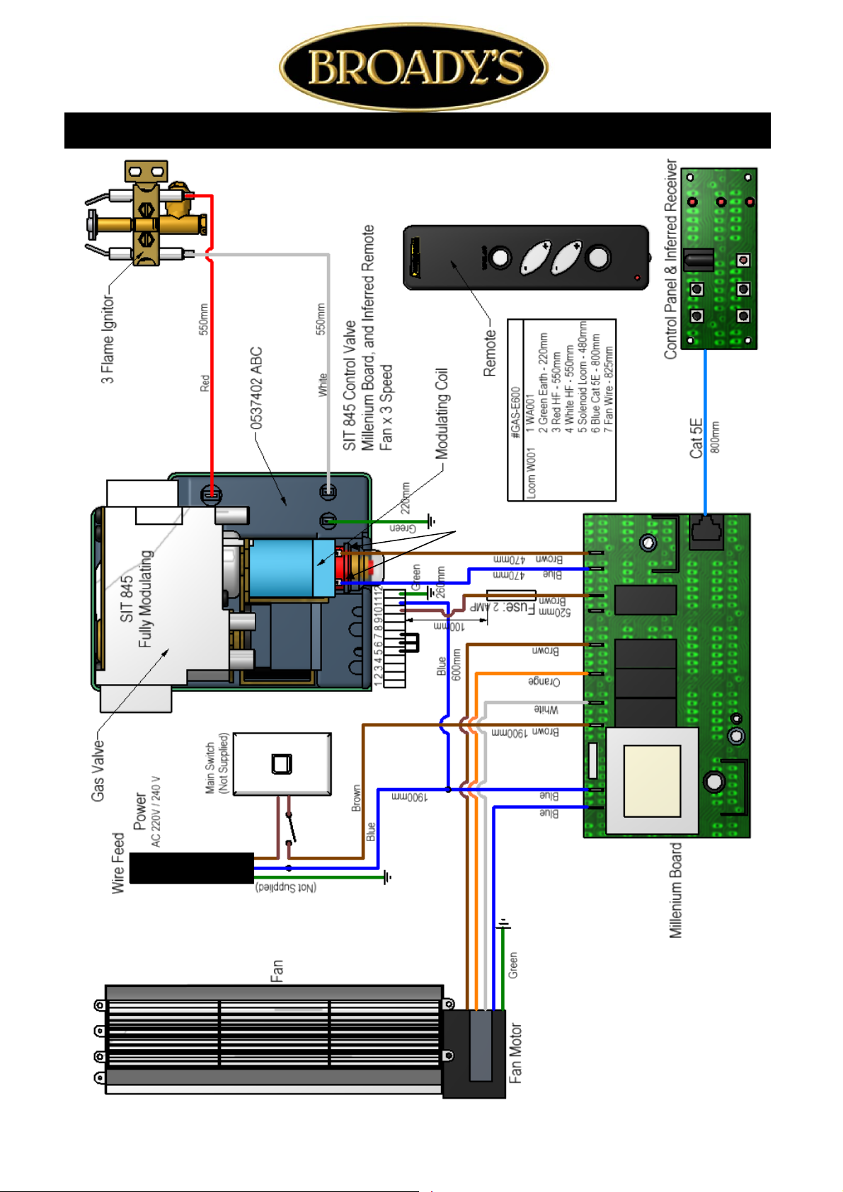
REMOTE IGNITION FpEG GAS FIRE WIRING DIAGRAM
14 December 2010
Modulator Harness
Connections
22
Due to continued product improvement, Broady’s reserves the right to change product specifications without prior notification.
All Dimension are in mm………….Copyright ©
 Loading...