

Page 1
Release 0.14
Paragon 3 Diesel
Technical Reference Manual
Page 2

2
INTRODUCTION
Introduction
The Paragon 3 sound unit is a multi-function DCC decoder that supports
the following:
DCC Characteristics
14 bit addressing
7 bit addressing (1-127)
Enhanced Lighting Control
Advanced Sound Support
Consist Support
14, 28 and 128 speed steps
Support for F0—F28 including remapping
Operations mode support for all CV settings
Configuration Variable Access Acknowledgement in Service mode
Direct, Address Only, Physical Addressing and Paged CV Addressing
Modes support in Service Mode including Write and Verify
Load Controlled Diesel Rev Level Sound Effects
Macro Event Recorder
DC characteristics
DCMaster uses Direct Mode for CV Programming
All CV’s Programmable and Readable
Enhanced Lighting Control
Advanced Sound Support
Consist Support
Enhanced Motor Control
Selectable DCMaster AUX Control
Load Controlled Diesel Rev Level Sound Effects
Please Note: CV defaults will vary between locomotives
Page 3
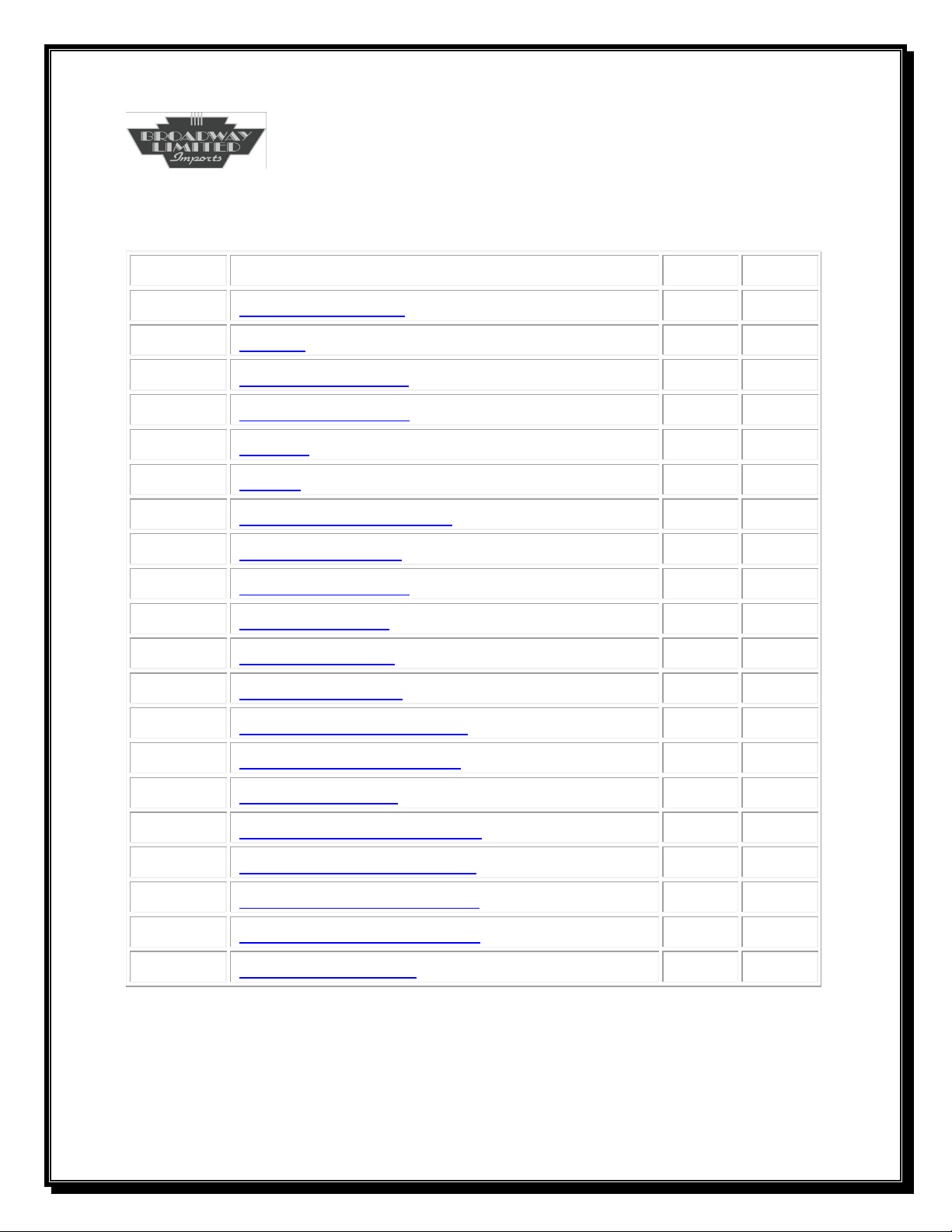
3
CV
Description
Initial
Yours
1
Primary Address
3
2
V Start
1
3
Acceleration Rate
5
4
Deceleration Rate
5
5
V High
250 6
V Mid
50
7
Manufacturer Version
?
8
Manufacturer ID
38
10
Back EMF Cutout
1
11
Packet Timeout
2
15
Unlock ID Code
0
16
Lock ID Number
0 17
Extended Address MSB
192 18
Extended Address LSB
128 19
Consist Address
0
21
Consist Functions Type 0
255
22
Consist Functions Type1
255
23
Acceleration Adjustment
0
24
Deceleration Adjustment
0
29
Configuration Bits
6
System CVs
Table
Page 4
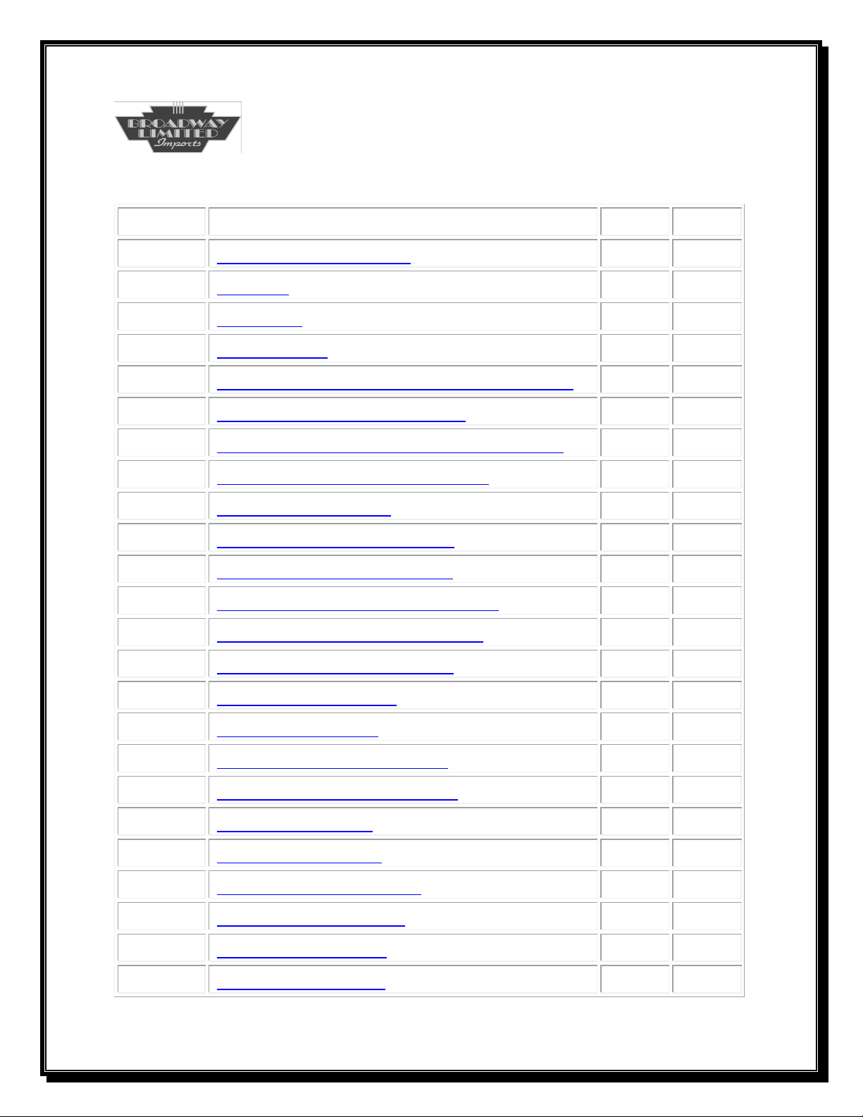
4
CV
Description
Initial
Yours
33
F0 (Front/Rear Lamp)
1
34
F1 (Bell)
2
35
F2 (Horn)
3
36
F3 (Coupler)
17
37
F4 (Grid Blower Motor and Compressor)
5 38
F5 (Ramp Diesel Engine Up)
6
39
F6 (Ramp Diesel Engine Down/Startup)
7
40
F7 (Smoke or L1 Visual Effects)
8
41
F8 (Master Volume)
9
42
F9 (Shutdown and Startup)
10
43
F10 (Radiator Cooling Fan)
11
44
F11 (Air Release and Air Filling)
12 45
F12 (Brake Set/Release/Squeal)
13 46
F13 (Horn Grade Crossing)
30 47
F14 (Station Sounds)
50
48
F15 (Yard Sounds)
51
49
F16 (Maintenance Sounds)
52
50
F17 (Radio Chatter Sounds)
53
51
F18 (City Sounds)
54
52
F19 (Farm Sounds)
55
53
F20 (Industrial Sounds)
56 54
F21 (Lumber Sounds)
57
55
F22 (Horn2 Toggle)
19
56
F23 (Track Sounds)
31
Function/Control CVs
Page 5
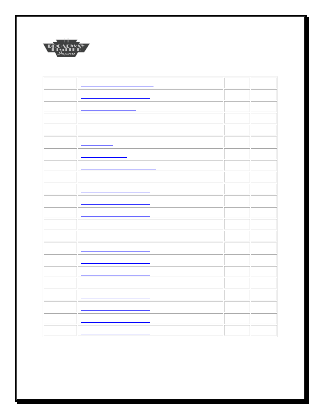
5
57
F24 (L1 Visual Effects)
8
58
F25 (Complete Horn)
20
59
F26 (Play Macro)
40
60
F27 (Record Macro)
41
61
F28 (Brake Squeal)
18
65
Kick Start
40 66
Forward Trim
0
67
Speed Table Entry One
6
68
Speed Table Entry …
16
69
Speed Table Entry …
24
70
Speed Table Entry …
34
71
Speed Table Entry …
42
72
Speed Table Entry …
52 73
Speed Table Entry …
60
74
Speed Table Entry …
70
75
Speed Table Entry …
78
76
Speed Table Entry …
89
77
Speed Table Entry …
97
78
Speed Table Entry …
107
79
Speed Table Entry …
115
80
Speed Table Entry …
125
81
Speed Table Entry …
133
Function/Control CVs
Page 6
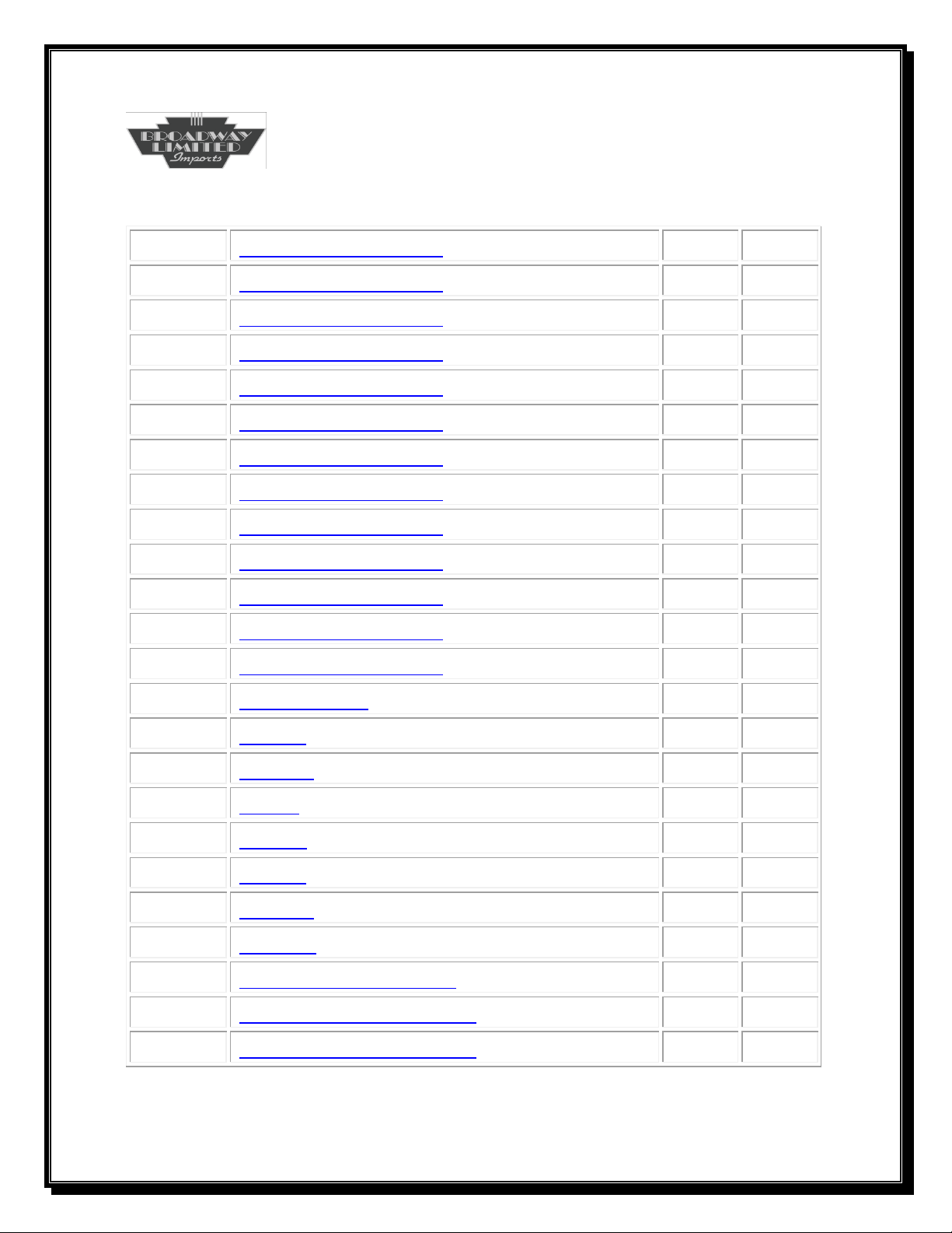
6
82
Speed Table Entry …
143
83
Speed Table Entry …
151
84
Speed Table Entry …
161
85
Speed Table Entry …
169
86
Speed Table Entry …
180
87
Speed Table Entry …
188 88
Speed Table Entry …
198
89
Speed Table Entry …
206
90
Speed Table Entry …
216
91
Speed Table Entry …
225
92
Speed Table Entry …
235
93
Speed Table Entry …
245
94
Speed Table Entry 28
255 95
Reverse Trim
0
112
KpLSB
0
113
KpMSB
32
114
KiLSB
50
115
KiMSB
1
116
KdLSB
0
117
KdMSB
0
118
KpSlow
20
120
Speed Step Smoothing
25
121
Consist Functions Type2
255
122
Consist Functions Type3
255
Function/Control CVs
Page 7
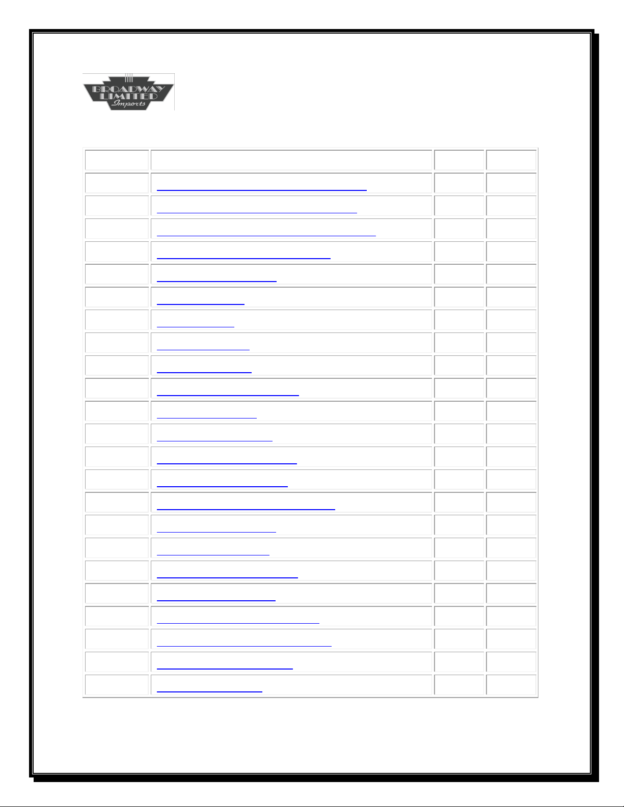
7
CV
Description
Initial
Yours
130
Master Volume Sound Increment
16
131
DC Sound Unit Startup Voltage
72
132
DC Sound Unit Shutdown Voltage
58
133
Sound Unit Master Volume
128
134
Maximum Volume
128 135
Horn Volume
128
136
Bell Volume
128
137
Diesel Volume
128
138
Horn2 Volume
128
139
Coupler Slack Volume
128
140
Couple Volume
128
141
Uncouple Volume
128 142
Wheel Flange Volume
128 143
Compressor Volume
128 144
Manual Air Release Volume
128
145
Air Filling Volume
128
146
Brake Set Volume
128
147
Brake Release Volume
128
148
Spit Valve Volume
128
149
Radiator Cooling Volume
128
150
Grid Blower Motor Volume
128 151
Brake Squeal Volume
128
152
Fuel Fill Volume
128
Sound CVs
Page 8
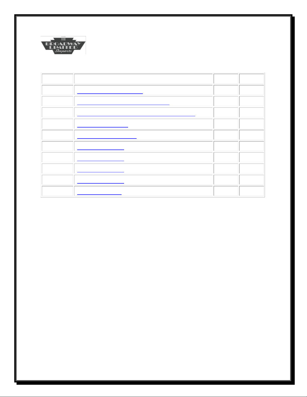
8
CV
Description
Initial
Yours
153
Station/Yard Volume
128
155
Maintenance/Chatter Volume
128
156
City/Farm/Industrial/Lumber Volume
128
159
System Lighting
2
160
L1 Light Definition
131 161
L1 Parameter 1
0
162
L1 Parameter 2
30
163
L1 Parameter 3
180
164
L1 Parameter 4
30
231
Light Dimmer
100
Lighting CVs
Page 9
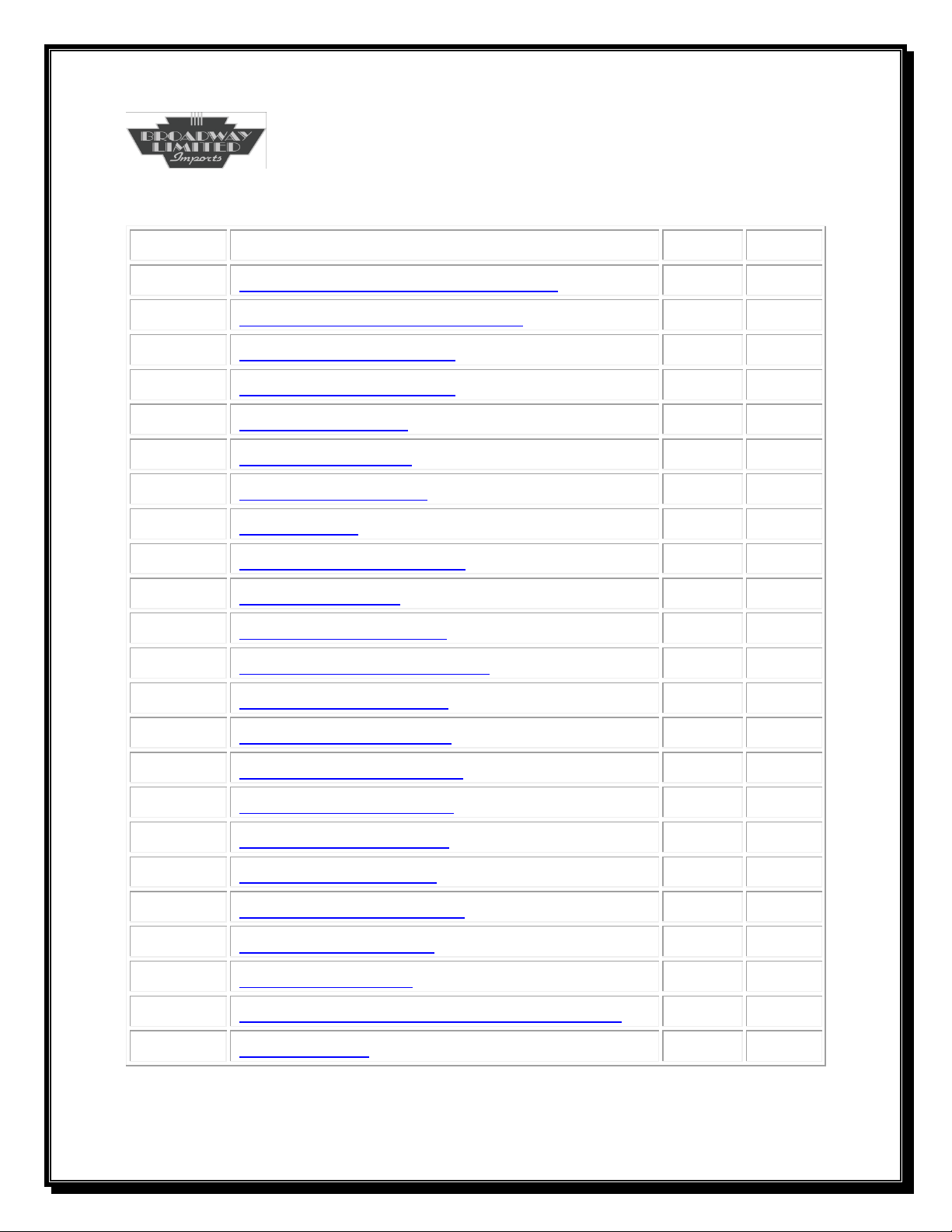
9
CV
Description
Initial
Yours
176
Fatal OverCurrent Configuration
114
177
Fatal OverCurrent Sensitivity
120
178
Coupler Slack Repeats
1
179
Coupler Slack Interval
100
180
Bell Ring Interval
Varies
184
DC Brake Control
20
185
DCC Brake Control
20
186
Brake Timer
3
187
Uncouple Throttle Stop
3
190
DC Sound Setup
x
191
DC Brake Set Voltage
70
192
DC Brake Release Voltage
77 193
Rev Level One Power
105
194
Rev Level Two Power
120
195
Rev Level Three Power
130
196
Rev Level Four Power
160
197
Rev Level Five Power
180
198
Rev Level Six Power
200
199
Rev Level Seven Power
220
201
N Gage Level Scalar
46
202
Load Power Filter
12
203
Ho Gage Rev Level Motor Power Scalar
50
204
Initial RevUp
1
Setup/Control CVs
Page 10
10
CV
Description
Initial
Yours
208
Cab Light Throttle Stop
3
209
DCC Brake Set Throttle Stop
0
210
DCC Brake Release Throttle Stop
1
212
Rolling Thunder Address
1
213
Rolling Thunder Setup
128 214
RollingThunder Volume
128
218
Smoke Unit Idle Set Point
70
219
Smoke Unit High Set Point
80
221
Unique Control One
Varies
222
AUX Select for DCMaster
Varies
223
Bell Select
0
224
Horn Select
0 225
Control One
3 226
Control Two
0 227
Control Three
2
228
DCC Start Up Timer
1
229
Extended Consist Features
247
230
Easy Consist
0
231
Light Dimmer
100
232
Fan Idle Power
8
233
Fan High Power
60 234
Fan Rev Up Power
80
235
Fan Rev Down Power
70
236
Fan Idle Delay
4
Setup/Control CVs
Page 11
11
CV
Description
Initial
Yours
238
Macro Recorder Control
79
239
Macro Playback Loop Adjust
0
240
Random Sound Generator Timer Low
4
241
Random Sound Generator High
20
242
Track Sounds
15 244
Grid Blower and BroadCast Stop Packets
32
245
General System Controls One
17
246
General System Controls Two
128
247
Over Current Delay
10
248
Enhanced DC Motor Startup Delay
60
249
DC Motor Off Voltage
70
250
DC Track Voltage Read Delay
0 251
DC Motor Control Vmax
120
252
DC Motor Control Vmin
92
Setup/Control CVs
Page 12

12
REV UP/DOWN
Control
Synopsis
The diesel engine may have its engine revved up or down at any throttle stop including
zero. Activating F5 or F6 (rev up/rev down) activates manual rev mode. A transition to
speed step zero resets manual throttle control back to automatic throttle control. Under
automatic throttle control the Rev Levels change up as the throttle is increased and
down as the throttle is decreased. The rev level only changes after the ramp up/ramp
down sound is finished and a throttle change is made. Motor power is also monitored
and the rev levels will change depending on overall load on the locomotive.
Manual
Manual mode may be activated at any throttle stop. Pressing F5 causes the diesel
engine to rev up one level per press.
Example: Power engine and start (F9). Press F5 three times. Notice the rev level
changes to rev level three. Increase the throttle stop to one.
Pressing F6 causes the diesel to rev down one level per press.
Example: After following the above example, press F6 once. Notice the rev level
changes to rev level two. Set the throttle stop to zero. The diesel now
automatically revs down to idle. Automatic mode is now engaged.
Automatic
Once the throttle stop is greater than zero, automatic mode is activated. Make sure that
F5 or F6 is not active. Throttle up from zero to one. The locomotive will rev up to
CV204 level. Now, if CV246 bit1 is zero (default) motor loading is enabled. The
locomotive rev levels now are controlled by two criteria; throttle changes and
locomotive loading.
Grid Blower Effects
Once the locomotive is notched up and moving, activating the grid blower motor
(CV37) automatically slowly notches the locomotive down, eventually to idle. A throttle
increase while the grid blower is active turns off the grid blower and throttle control is
returned. Setting the throttle to zero disables the grid blower.
Page 13

13
REV UP/DOWN (cont)
Locomotive Loading Rev Control
The locomotive power is monitored and filtered according to several CV’s. CV193
through CV199 contain thresholds determining the required locomotive power needed
to increase or decrease the diesel rev level. Once the power level falls above or below
the threshold, the rev level changes. CV202 contains a filter coefficient determining the
convergence time and accuracy in measuring the locomotive’s power.
The locomotive power is substantially higher in DC mode. To compensate, a DC scalar
is provided at CV200. This scalar changes the thresholds of CV193 through CV199,
altering the power load thresholds providing proper rev changes from power load
changes in DC mode of operation.
The locomotive power is substantially lower for N Gage locomotives. To compensate,
an N Gage scalar is provided at CV201. This scalar changes the thresholds of CV193
through CV199, altering the power load thresholds providing proper rev changes from
power load during operation.
Should the desired power thresholds need to be changed, a simple tuning method may
be used. Set CV193 through CV199 all to 255. Now, all power thresholds are disabled.
While running in DCC, change CV193, lowering it until the rev changes at the desired
power load. Repeat for each of the other six power levels. DC mode will require more
work, since changing while running is not allowed.
Setting bit1 in CV246 will disable locomotive load power control.
Locomotive Throttle Rev Control
The rev levels also change with the throttle. Once the rev up or rev down transition
sound effect finishes playing, the throttle is checked for any change. A rev up sound
effect plays if the throttle change is increased. A rev down sound effect plays if the
throttle change is decreased. The effect is that if the throttle is slowly increased or
decreased, the revs continue to increase or decrease. If the throttle is quickly moved up
or down, the throttle will only change one rev level up or down.
Page 14

14
Advanced DC Motor Control
Dc operation with sounds creates a dilemma. The train usually will start moving at a very low
track voltage, to low to power a loudspeaker with high quality sounds. A higher voltage of
operation for the motor is an acceptable solution. About 8.0 volts is necessary before this sound
system can function, producing loud, high quality sounds, with the motor powered and the train
beginning to move. This motor controller gives acceptable motor control at the necessary power
levels, allowing the sound system to start at a much lower voltage, keeping the motor from
stealing the power from the sound system until enough power exists to move the train without
the sounds degrading or shutting off. Also, more overall power is diverted to the motor at top
speeds. The maximum train speed is higher with this advanced DC motor controller.
DC motor control may be altered by changing the control curve as well as the power curve.
CV249, CV251 and CV252 determine the control range for DC operations. Altering these values
changes the train’s startup behavior relative to track voltage and at what control voltage full
speed is attained. The power curve may be altered by the speed table (CV2, CV5, CV6) if CV29
bit4=0 or (CV66 through CV95) CV29 if bit4=1. CV29 bit2 must be equal to 1.
CV249
CV249 defines the maximum track control voltage without applying motor power. Valid values
for CV249 are 0-255. The distance between CV249 and CV252 and must be large enough to
keep the control voltage (Track Voltage) from moving between motor off and motor on due to
track voltage variances. CV249 must be smaller than CV252
Vmin
Vmin (CV252) defines the track voltage that applies the lowest or starting motor power. Valid
values for Vmin are 0-255. The distance between Vmin and Vmax (Vmax > Vmin) is the
control range. This control voltage value determines the locomotive speed.
Note: Vmin < Vmax. Too low a value for Vmin may cause the sound unit to reset when
power is supplied to the motor.
Vmax
Vmax (CV251) defines track voltage that once reached sets the locomotive to its fastest speed.
Valid values for Vmax are 0-255. Increasing Vmax means a higher track control voltage is
needed before the maximum speed is reached.
Note: Vmax > Vin. Too high a value for Vmax may not allow the train to reach full speed.
Page 15
15
0
20
40
60
80
100
120
2 4 6 8 10 12 14 16 18
Speed`
Track Voltage
DC Mode Motor Control
Track Voltage
Control Range
DC Motor Control
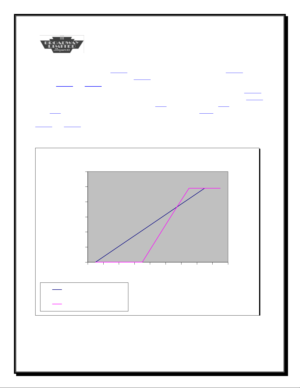
Figure one illustrates a locomotive running in DC mode. The sound unit supplies full sound
volume at about 8.0 volts (See CV131) and shuts down at about 7.5 volts (See CV132). Motor
power is supplied around 8.5 volts (See CV252). Between 8.5 volts and 14 volts (The Control
Range—CV252 and CV251), the sound unit monitors the track voltage and increase or decreases
the motor speed as noted by the slope of control range in figure one. At about 14 volts (CV251),
maximum speed is set. Motor power is removed once the control voltage falls below CV249.
Please note that this DC controller honors vStart (CV2), Acceleration Rate (CV3), Deceleration
Rate (CV4) as well as the CV’s used for the speed control as set by CV29 bit 4. By using these
CV’s, the DC operation is smooth starting and stopping, comparing to DCC operations. Using
CV245 and CV248 allows realistic sound synchronization to the startup and brake release before
the locomotive begins to move.
Figure 1
Page 16

16
Enhanced Sounds
Station Sounds
Station Sounds are activated with the F14 Function Key.
From an initial power up start condition, press F14. A Station Sounds
effect will play every time F14 is pressed. Once the locomotive starts
moving and for 10 seconds 1 of 4 different Station Departure sound
effects will play. Note: If a Yard sound effect key is defined and
pressed as the last key before moving the locomotive, than the 1 of 4
different sounds playing during the 10 second period of time will be
Yard Departure sounds.
After 10 seconds, all Station Sounds are off and will not play unless
F14 is pressed again. From this moving condition and after 10
seconds, pressing F14 plays an arrival sound effect once and on
subsequent presses of F14, plays 1 of 3 different arrival sound effects
until the locomotive stops. Once stopped, 1 of 4 different sound
effects will continue to play until the F14 is pressed again. The
sequence now repeats.
At any time when the locomotive is stopped, throttling up and down
within 10 seconds will de-activate the Station sounds. Reactivation is
accomplished by pressing the F14 key again.
Station Sounds may also be activated for just the arrival. Press F14
after 10 seconds of movement and hear just the arrival sounds. Once
stopped, throttle to one and then zero.
Page 17

17
Enhanced Sounds
Yard Sounds
Yard Sounds are activated with the F15 Function Key.
From an initial power up start condition, press F15. A Yard Sounds
effect will play every time F15 is pressed. Once the locomotive starts
moving and for 10 seconds 1 of 4 different Yard Departure sound
effects will play. Note: If a Station sound effect key is defined and
pressed as the last key before moving the locomotive, than the 1 of 4
different sounds playing during the 10 second period of time will be
Station Departure sounds.
After 10 seconds, all Yard Sounds are off and will not play unless F15
is pressed again. From this moving condition and after 10 seconds,
pressing F15 plays a sound effect once and on subsequent presses of
F15, plays 1 of 3 different sound effects until the locomotive stops.
Once stopped, 1 of 4 different sound effects will continue to play
until the F15 is pressed again. The sequence now repeats.
At any time when the locomotive is stopped, throttling up and down
within 10 seconds will de-activate the Yard sounds. Re-activation is
accomplished by pressing the F15 key again.
Yard Sounds may also be activated for just the arrival. Press F15 after
10 seconds of movement and hear just the arrival sounds. Once
stopped, throttle to one and then zero.
Page 18

18
Consists Configuration
Synopsis
Consisting multiple DCC locomotives has become a daunting task due to more advanced lighting
and sounds used in modern sound decoders. In addition, two methods are used by most DCC
controllers to manage these consists. These two methods are Advanced Consists and Universal
Consists.
Universal Consist
Universal consists are those that the controller remembers and interprets all commands, sending
out appropriate DCC commands to all engines in an addressed consist. With a universal consist,
proper sound functioning will be at best difficult, since there is no NMRA definitions for sounds
beyond horn and bell. Which horns, bells and other sounds should play on each engine part of
the consist is important in the consist though. A decoder has no control over the universal
consist and this consist is not portable to other layouts. The controller is configured to remember
what engine ID’s belong to what consist ID and which engines receive the programmed function
commands. Now, is not that easy?
Advanced Consist
The advanced consist is defined by the NMRA. CV19 contains a number from 0-127 or 129 to
255. What do these numbers mean?
0 and 128 Indicates the engine does not belong to any consist
1-127 Defines the consist 1 to 127
129-255 Defines consists 1 to 127 but with reverse lighting (129 is consist 1 reverse
lighting)
So now the consist may be set within CV19, but what is the relationship between the engine ID
and its active consist ID? Once the engine is part of a consist, certain NMRA rules exist for
functions (F0-F12). Rules for the engine ID addressed as the engine ID that is part of a consist
are different than the rules for the engine ID addressed as the consist ID. Whew! Lets look at
what this means!
Page 19
19
Consists (Continued)
Addressing the engine ID while the engine is part of an active consist results in the following:
1. Speed and direction requests are ignored unless the engine ID is the same as the consist
ID.
2. All functions (F0-F12) are honored.
3. CV’s may be changed.
Addressing the active consists ID results in the following:
1. Speed and direction are honored
2. All functions (F0-F12) are honored or ignored depending on CV21 and CV22
3. CV’s may not be changed
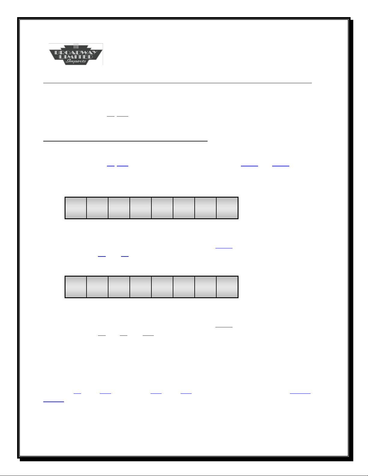
Bit 7 Bit 0
F8 F7 F6 F5 F4 F3 F2 F1
CV21
The decoder responds to all functions that have a “1” set in CV21 and defines which function
keys are active for F1 thru F8. Default is all set to “1”.
Bit 7 Bit 0
nu nu F12 F11 F10 F9 nu F0
CV22
The decoder responds to all functions that have a “1” set in CV22 and defines which function
keys are active for F0 and F9 thru F12. Default is all set to “1”. nu=not used.
So, depending on where the engine is in the consist, Function keys may be enabled or disabled.
For instance, the horn may be functioning in only the forward facing engine and disabled in the
other engines in the consist.
Our sound decoder supports the NMRA standard and allows the enabling/disabling of these
functions F0 thru F12. Similiarly, F13 thru F28 may be enabled/disabled with CV121 and
CV122.
So now we may program a consist and configure how each engine handles the function keys.
But what about other lighting and sounds not covered by NMRA standards?
Page 20
20
Consists (Continued)
Advanced Lighting
Other lighting needs to be controlled in a similar manner. Our decoder allows consist setup for
advanced lighting using CV229.
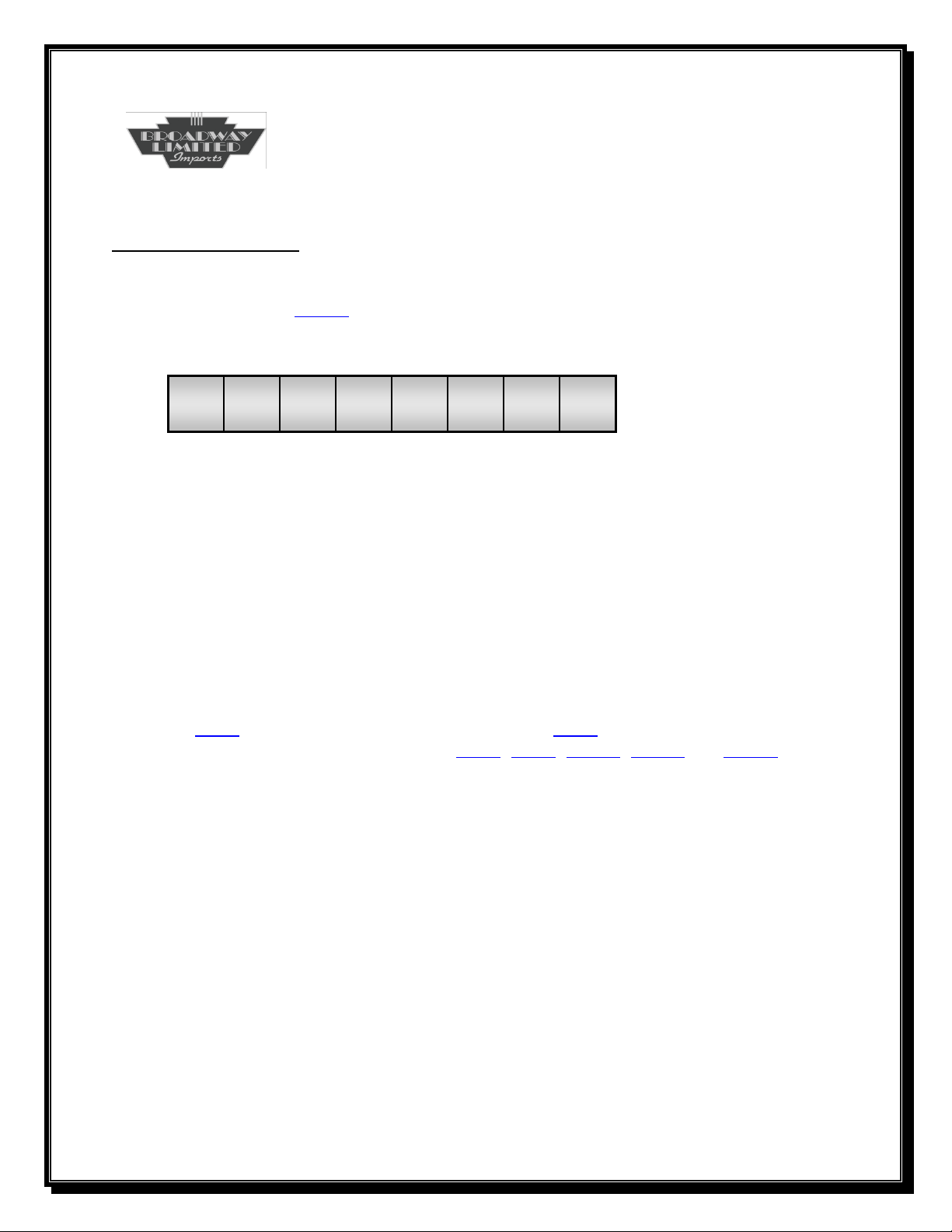
Bit 7 Bit 0
x x x x x x x x
CV229
Bit7: Cab Disabled=0; Cab Enabled=1
Bit6: Horn Enabled=1 (DC Only)
Bit5: Bell Enabled=1 (DC Only)
Bit4: AUX Enabled=1 (DC Only)
Bit3: Not used
Bit2: L1 Disabled=0; L1 Enabled=1
Bit1: Front Light Disabled=0; Front Light Enabled=1
Bit0: Rear Light Disabled=0; Rear Light Enabled=1
When the locomotive is part of a consist, this CV allows individual lighting. So now, let see
how we can configure an engine in a consist. Set the engine ID to engine 3. Now, set a consist
address at CV19. Lets make it consist 60. So program CV19 to 60. Now we need to know
where the engine is located in the consist so CV21, CV22, CV121, CV122 and CV229 may be
set correctly.
Page 21

21
Consists (Continued)
For a Front Engine forward facing:
CV21=255 F1 thru F8 enabled for consist address
CV22=255 F0 and F9 thru F12 enabled for consist address
CV121=255 F13 thru F20 are enabled for consist address
CV122=255 F21 thru F28 are enabled for consist address
CV229=246 Cab light enabled; DC Horn enabled; DC Bell enabled; AUX enabled; L1
enabled; Front light enabled; Rear light disabled
AUX enabled
For a Middle Engine:
CV21=176 F1, F2, F3, F4, F7 disabled and F5, F6 and F8 enabled for consist address
CV22=5 F0 and F10 thru F12 disabled and F9 enabled for consist address
CV121=255 F13 thru F20 are disabled for consist address
CV122=96 F26 and F27 are enabled for consist address
CV229=0 Cab light disabled; DC Horn disabled; DC Bell disabled; AUX disabled;
L1 disabled; Front light disabled; Rear light disabled
Note: F8 and F9 allow for consist starting, shutdown, volume control and muting. F5 and F6
allow manual rev control.
For a Rear Engine forward facing:
CV21=176 F1, F2, F3, F4, F7 disabled and F5, F6 and F8 enabled for consist address
CV22=5 F0 and F10 thru F12 disabled and F9 enabled for consist address
CV121=255 F13 thru F20 are disabled for consist address
CV122=96 F26 and F27 are enabled for consist address
CV229=2 Cab light disabled; DC Horn disabled; DC Bell disabled; AUX disabled;
L1 disabled; Front light enabled; Rear light disabled
Note: F8 and F9 allow for consist starting, shutdown, volume control and muting. F5 and F6
allow manual rev control.
Page 22

22
Consists (Continued)
Easy Consist Programming
Now that we can program a consist, let consider an easy way to program a generic consist.
CV230 for advanced DCC or DC consist performs the consisting functions for you.
Easy Consist (CV230)
The easy consist feature sets the decoder CV19 for consist 60. Program CV230 with 1, 2 or 3 to
set the engine position in the consist.
0 = Consist Disabled
1 = Front Engine
All consist function keys are enabled (CV21, CV22)
All lights except the rear light are enabled (CV229)
2 = Middle Engine
All consist function keys except F0, F5, F6, F8, F9, F26 and F27 are disabled (CV21,
CV22, CV121, CV122); All lights are disabled (CV229)
3 = Rear Engine
All consist function keys except F0, F5, F6, F8 , F9, F26 and F27 are disabled
(CV21, CV22, CV121, CV122). Only the front light is enabled (CV229)
Now, program CV19 from 60 to whatever consist number you desire. Repeat for each engine
and the consist is completed.
Page 23
23
Decimal to Binary Primer
Setting CV’s
Setting the CV’s requires knowledge of conversion between binary
and decimal. The following examples demonstrates the conversion
process from binary to decimal after determining which bits in a CV
need to be “1” and which needs to be “0”. The tables are also useful
for converting binary to decimal.
Reading CV’s
The tables are also useful for converting decimal to binary when
reading the CV’s in service mode. After reading the CV, use the
tables to determine which bits are “1” and which bits are “0”. Once
the bit patterns are identified, find the CV in this manual to
determine what functions are controlled by the bits.
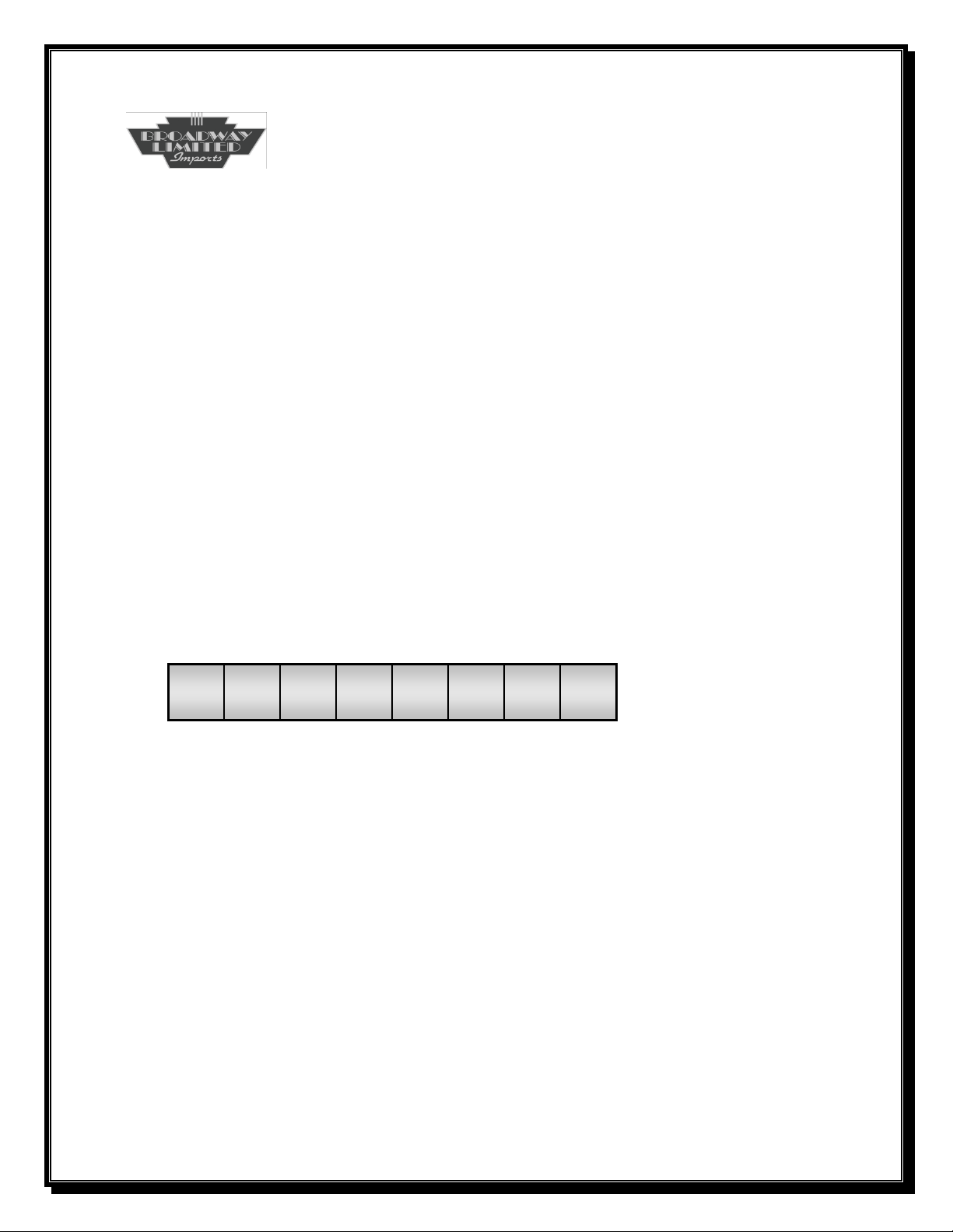
Bit 7 Bit 0
27 26 25 24 23 22 21 2
128 64 32 16 8 4 2 1
0
Consider a binary number 10001011
128+0+0+0+8+0+2+1=139
Consider a binary number 00011101
0+0+0+16+8+4+0+1=29
CVxx read is 39. Table lookup is: 00100111
Page 24
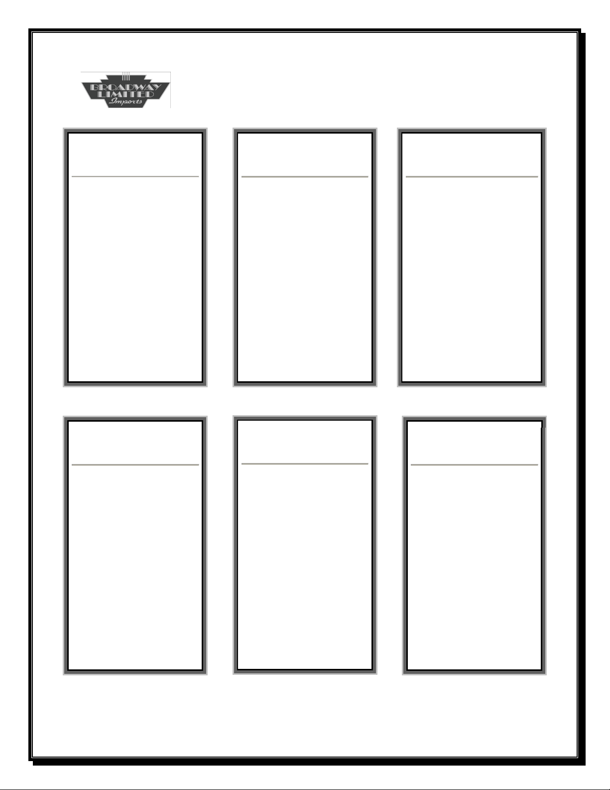
Dec Hex Oct Bin
0
1
2
3
4
5
6
7
8
9
10
11
12
13
14
15
0
1
2
3
4
5
6
7
8
9
A
B
C
D
E
F
000
001
002
003
004
005
006
007
010
011
012
013
014
015
016
017
00000000
00000001
00000010
00000011
00000100
00000101
00000110
00000111
00001000
00001001
00001010
00001011
00001100
00001101
00001110
00001111
Dec Hex Oct Bin
16
17
18
19
20
21
22
23
24
25
26
27
28
29
30
31
10
11
12
13
14
15
16
17
18
19
1A
1B
1C
1D
1E
1F
020
021
022
023
024
025
026
027
030
031
032
033
034
035
036
037
00010000
00010001
00010010
00010011
00010100
00010101
00010110
00010111
00011000
00011001
00011010
00011011
00011100
00011101
00011110
00011111
Dec Hex Oct Bin
32
33
34
35
36
37
38
39
40
41
42
43
44
45
46
47
20
21
22
23
24
25
26
27
28
29
2A
2B
2C
2D
2E
2F
040
041
042
043
044
045
046
047
050
051
052
053
054
055
056
057
00100000
00100001
00100010
00100011
00100100
00100101
00100110
00100111
00101000
00101001
00101010
00101011
00101100
00101101
00101110
00101111
Dec Hex Oct Bin
48
49
50
51
52
53
54
55
56
57
58
59
60
61
62
63
30
31
32
33
34
35
36
37
38
39
3A
3B
3C
3D
3E
3F
060
061
062
063
064
065
066
067
070
071
072
073
074
075
076
077
00110000
00110001
00110010
00110011
00110100
00110101
00110110
00110111
00111000
00111001
00111010
00111011
00111100
00111101
00111110
00111111
Dec Hex Oct Bin
64
65
66
67
68
69
70
71
72
73
74
75
76
77
78
79
40
41
42
43
44
45
46
47
48
49
4A
4B
4C
4D
4E
4F
100
101
102
103
104
105
106
107
110
111
112
113
114
115
116
117
01000000
01000001
01000010
01000011
01000100
01000101
01000110
01000111
01001000
01001001
01001010
01001011
01001100
01001101
01001110
01001111
Dec Hex Oct Bin
80
81
82
83
84
85
86
87
88
89
90
91
92
93
94
95
50
51
52
53
54
55
56
57
58
59
5A
5B
5C
5D
5E
5F
120
121
122
123
124
125
126
127
130
131
132
133
134
135
136
137
01010000
01010001
01010010
01010011
01010100
01010101
01010110
01010111
01011000
01011001
01011010
01011011
01011100
01011101
01011110
01011111
Decimal to Hexadecimal Conversion
24
Page 25
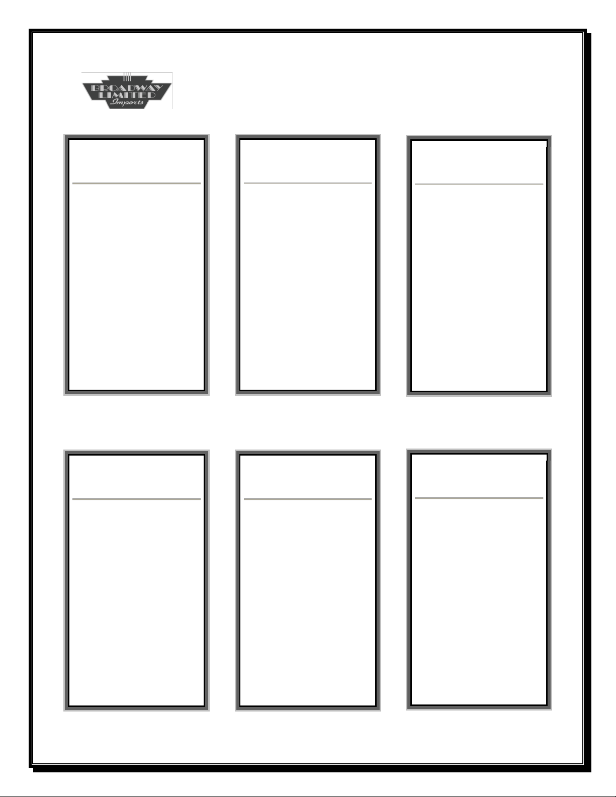
Dec Hex Oct Bin
96
97
98
99
100
101
102
103
104
105
106
107
108
109
110
111
60
61
62
63
64
65
66
67
68
69
6A
6B
6C
6D
6E
6F
140
141
142
143
144
145
146
147
150
151
152
153
154
155
156
157
01100000
01100001
01100010
01100011
01100100
01100101
01100110
01100111
01101000
01101001
01101010
01101011
01101100
01101101
01101110
01101111
Dec Hex Oct Bin
128
129
130
131
132
133
134
135
136
137
138
139
140
141
142
143
80
81
82
83
84
85
86
87
88
89
8A
8B
8C
8D
8E
8F
200
201
202
203
204
205
206
207
210
211
212
213
214
215
216
217
10000000
10000001
10000010
10000011
10000100
10000101
10000110
10000111
10001000
10001001
10001010
10001011
10001100
10001101
10001110
10001111
Dec Hex Oct Bin
144
145
146
147
148
149
150
151
152
153
154
155
156
157
158
159
90
91
92
93
94
95
96
97
98
99
9A
9B
9C
9D
9E
9F
220
221
222
223
224
225
226
227
230
231
232
233
234
235
236
237
10010000
10010001
10010010
10010011
10010100
10010101
10010110
10010111
10011000
10011001
10011010
10011011
10011100
10011101
10011110
10011111
Dec Hex Oct Bin
160
161
162
163
164
165
166
167
168
169
170
171
172
173
174
175
A0
A1
A2
A3
A4
A5
A6
A7
A8
A9
AA
AB
AC
AD
AE
AF
240
241
242
243
244
245
246
247
250
251
252
253
254
255
256
257
10100000
10100001
10100010
10100011
10100100
10100101
10100110
10100111
10101000
10101001
10101010
10101011
10101100
10101101
10101110
10101111
Dec Hex Oct Bin
176
177
178
179
180
181
182
183
184
185
186
187
188
189
190
191
B0
B1
B2
B3
B4
B5
B6
B7
B8
B9
BA
BB
BC
BD
BE
BF
260
261
262
263
264
265
266
267
270
271
272
273
274
275
276
277
10110000
10110001
10110010
10110011
10110100
10110101
10110110
10110111
10111000
10111001
10111010
10111011
10111100
10111101
10111110
10111111
Dec Hex Oct Bin
112
113
114
115
116
117
118
119
120
121
122
123
124
125
126
127
70
71
72
73
74
75
76
77
78
79
7A
7B
7C
7D
7E
7F
160
161
162
163
164
165
166
167
170
171
172
173
174
175
176
177
01110000
01110001
01110010
01110011
01110100
01110101
01110110
01110111
01111000
01111001
01111010
01111011
01111100
01111101
01111110
01111111
Decimal to Hexadecimal Conversion
25
Page 26
SYSTEM CVs
CV1
Primary Address
Description
The Decoders Primary Address is Stored Here
Values
Bits 0-6 contain an address with a value between 1 and 127
Initial Value
3 (Engine 3)
Related CVs
CV29 Bit 5
CV17, CV18, CV19
Bit 7 Bit 0
0 A6 A5 A4 A3 A2 A1 A0
The decoder responds to all valid commands if the address matches
the value in CV1 and CV29 Bit 5 is set to 0.
Programming CV1 will program CV19 (Consists Address) to zero
and programs CV29 Bit 5 to 0 (Extended Addressing Off).
26
Page 27
SYSTEM CVs
CV2
Vstart
Description
This Value Determines the Motor Speed at Step One
Values
0-255
Initial Value
1
Related CVs
CV5, CV6, CV66, CV95, CV29 Bit 4, CV120
Bit 7 Bit 0
0 0 0 0 0 0 0 1
CV2 determines the motor speed at step one if CV29 bit 4 is zero.
Increasing CV2 increases the initial motor start speed. If BackEMF is
disabled, this value must be high enough to overcome the initial
locomotive inertia (See also CV65 kickstart). Note: CV2 must be
smaller than Vmid and Vhigh.
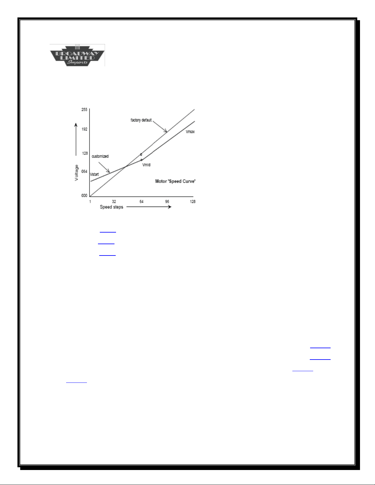
CV2, CV5, CV6, CV65 and CV95 allow motor control using a simple
line function. The start speed, the maximum speed, the mid range
speed and compensation for a motor that runs faster in one direction
or the other are determined by these 5 CV’s. Whether BackEMF is
enabled or not (CV10), the following graph illustrates how the CV’s
control the motor speed characteristics.
27
Page 28
Three Point Motor Control
Analysis
Vstart is CV2
Vmid is CV6
Vmax is CV5
Whether the speed steps are set to 14, 28 or 126, the above graph
illustrates how these CV’s control the motor speed. The midpoint is
63 for 126-speed step mode, 14 for 28-speed step mode and 7 for 14speed step mode. DC mode is fixed at 126 speed steps.
In addition, should the forward or reverse direction speeds not be
matched, a small correction may be applied to either direction. CV65
allows a small increase or decrease in forward speed while CV95
allows a small increase or decrease in reverse speed. (See CV65 and
CV95).
Note that whether operating in DCC or DC, the above CV’s control
the speed of the motor.
28
Page 29
SYSTEM CVs
CV3
Acceleration Rate
Description
This Value Determines the Locomotives Acceleration Rate
Values
0-255
Initial Value
5
Related CVs
CV4, CV23, CV24, CV120
Bit 7 Bit 0
0 0 0 0 0 1 0 1
The value sets the delay between each speed step change and creates
a momentum effect. The delay varies with the number of speed steps
selected. The acceleration rate is determined as follows:
Seconds = CV3 x 0.896 Number of Speed Steps
CV3=20 17.92 seconds for full speed
CV3=255 3.8 minutes for full speed
Note: CV23 is an additional acceleration rate that adds or subtracts
to CV3 during active consists.
29
Page 30
SYSTEM CVs
CV4
Deceleration Rate
Description
This Value Determines the Locomotives Deceleration Rate
Values
0-255
Initial Value
5
Related CVs
CV3, CV23, CV24, CV120
Bit 7 Bit 0
0 0 0 0 0 1 0 1
The value sets the delay between each speed step change and creates
a momentum effect. The delay varies with the number of speed steps
selected. The deceleration rate is determined as follows:
Seconds = CV4 x 0.896 Number of Speed Steps
CV4=20 17.92 seconds from full speed to stop
CV4=255 3.8 minutes from full speed to stop
Note: CV24 is an additional deceleration rate that adds or subtracts
to CV4 during active consists.
30
Page 31
SYSTEM CVs
CV5
Vhigh
Description
This Value Determines the Maximum Speed of the Selected Speed
Setting
Values
0-255
Initial Value
250
Related CVs
CV2, CV6, CV66, CV95, CV29 Bit 4
Bit 7 Bit 0
1 1 1 1 1 0 1 0
CV5 determines the motor speed at the maximum speed step (14, 28
or 126) if CV29 bit 4 is zero. Decreasing CV5 decreases the maximum
motor speed.
Note: CV5 must be larger than Vstart and Vmid.
See the Graph for CV2 for additional information.
31
Page 32
SYSTEM CVs
CV6
Vmid
Description
This Value Determines the Mid Speed of the Selected Speed Setting
Values
0-255
Initial Value
50
Related CVs
CV2, CV3, CV66, CV95, CV29 Bit 4
Bit 7 Bit 0
0 0 1 1 0 0 1 0
CV6 determines the motor speed at half the maximum step or the
midpoint (7 for 14 step, 14 for 28 step or 63 for 126 step) if CV29 bit 4
is zero. This value allows finer or courser control for the first half of
second half of the throttle control. If CV6 is zero, this value is not
used in the 3 point curve calculation.
Note: CV6 must be larger than Vstart and smaller than Vhigh.
See the Graph for CV2 for additional information.
32
Page 33
SYSTEM CVs
CV7
Manufacturer Version Number
Description
The Decoders Read Only Type/Revision is Stored Here
Values
Initial Value
Related CVs
None
Bit 7 Bit 0
D7 D6 D5 D4 D3 D2 D1 D0
This value cannot be modified.
000xxxxx = Diesel and xxxxx is the revision.
001xxxxx = Steam and xxxxx is the revision.
33
Page 34
SYSTEM CVs
CV8
Manufacturer ID
Description
The Decoders NMRA Assigned Number is Stored Here. Broadway
Limited is assigned ID 38.
Values
Initial Value
38
Related CVs
Bit 7 Bit 0
0 0 1 0 0 1 1 0
Writing “value” to CV8 causes the following:
VALUE
8 Resets all CVs back to their original manufactured
values unless the unit is locked.
10 Loads and Saves Factory Stored Macro
12 Loads Factory Motor Test Tune
16 Saves Recorded Macro
38 Sets F0 thru F12 to match the Blue Line engine
function keys
113 Sets F0 thru F12 to match QSI engine function keys
141 Sets F0 thru F12 to match SoundTraxx engine
function keys
254 Resets all CVs back to their original manufactured
values even if the unit is locked.
34
Page 35
SYSTEM CVs
CV10
EMF Feedback Cutout
Description
This Value Determines Whether BackEMF is Enabled or Disabled
Values
0-1
Initial Value
1
Related CVs
CV2, CV65
Bit 7 Bit 0
0 0 0 0 0 0 0 1
Writing a one to this location enables backEMF or speed control and
writing a zero disables speed control. If back EMF is disabled, CV65
or the kickstart may be used to help the locomotive start from speed
step 0 to speed step one by supplying a momentary increase of power
overcoming the initial locomotives inertia (See CV65). Also, CV2 may
need to be increased to keep the locomotive running at the lowest
speed possible.
35
Page 36
SYSTEM CVs
CV11
Packet Time-Out Value
Description
Maximum Time in Seconds Between Valid DCC Packets Before a
Throttle Shutdown Occurs
Values
0-255
Initial Value
2
Related CVs
Bit 7 Bit 0
0 0 0 0 0 0 1 0
This value determines the maximum time elapsed before a throttle
shutdown occurs from not receiving a valid DCC packet. If the
shutdown occurs, the locomotive will be shutdown at the rate
determined by CV4 and CV24.
Note: This shutdown only occurs if CV29 bit 2=0. System default is
CV29 bit2=1.
36
Page 37
SYSTEM CVs
CV15
Unlock ID Code
Description
The Number is the Unlock ID
Values
0-7
Initial Value
0
Related CVs
CV16
Bit 7 Bit 0
0 0 0 0 0 0 0 0
Factory new units have the unlock id code and the lock id number set
to zero, allowing normal programming of all CV’s. Users wishing to
lock this decoder may start by programming CV16 with a
recommended value of 2. Now, unlock the decoder for CV updates
by writing 2 to CV15. Once all programming is completed, write a
value of 0 to CV15. Now the decoder is locked. Please note once the
decoder is locked, no CV’s other than CV1 or CV15 may be read or
changed.
37
Page 38
SYSTEM CVs
CV16
Lock ID Number
Description
This Number Identifies this Single Decoder.
Values
0-7
Initial Value
0
Related CVs
CV15
Bit 7 Bit 0
0 0 0 0 0 0 0 0
This value may only be changed when CV15 equals CV16. CV15
may always be read. The following definitions may be used when
programming this number:
Lock Disabled 0
Motor Decoder 1
Sound Decoder 2
Function Decoder 3
If this feature is use, the recommendation is to program a 2 for value.
Please note once the decoder is locked, no CV’s other than CV1 or
CV15 may be read or changed.
38
Page 39
SYSTEM CVs
CV17 and CV18
Extended Address
Description
This Value Contains the Decoders Extended Address and is Valid
Only if CV29 Bit 5 is 1
Values
Values From 0 to 10239 are Valid
Initial Value
1100 0000 1000 0000 (Engine 128)
Related CVs
CV29 Bit 5
Bit 15 Bit 8
1 1 A13 A12 A11 A10 A9 A8
CV17 Extended Address MSB
Bit 7 Bit 0
A7 A6 A5 A4 A3 A2 A1 A0
CV18 Extended Address LSB
CV17 Valid Values are 1100 0000 thru 1110 0111
CV18 Valid Values are 0000 0000 thru 1111 1111
39
Page 40
SYSTEM CVs
CV19
Consist Address
Description
The Decoders Consist Address is Stored Here
Values
0-255
Initial Value
0
Related CVs
CV21, CV22, CV225, CV229
Bit 7 Bit 0
Dir A6 A5 A4 A3 A2 A1 A0
Consist valid address are 1-127 or A6-A0 where a value of 0 breaks
the consist and all received consist commands are ignored. The Dir
bit selects normal or reverse directional lighting. If Dir=0 than normal
directional lighting is selected. If Dir=1 than reverse directional
lighting is selected. Reverse directional lighting is useful when the
engine is oriented backwards in the consist.
See Consist Synopsis.
40
Page 41
SYSTEM CVs
CV21
Consist Functions Type 0
Description
Determines Which Functions (F1-F8) are Allowed in the Consist
Values
0-255
Initial Value
255
Related CVs
CV19, CV22, CV121, CV122, CV225, CV226, CV229
Bit 7 Bit 0
F8 F7 F6 F5 F4 F3 F2 F1
The decoder responds to all functions that have a “1” set in this CV
once a consist is configured. A consist is configured by CV19
programmed to a value from 1-127. A value of 0 breaks the consist.
See CV19. This CV is used to configure the engine for a front, middle
or end in the consist.
An example for consist number 60:
CV19=60
Front Engine CV21=255 CV22=255 CV121=255 CV122=255 CV229=246
Middle Engine CV21=176 CV22=5 CV121=0 CV122=96 CV229=0
Rear engine CV21=176 CV22=5 CV121=0 CV122=96 CV229=2
See Consist Synopsis.
41
Page 42

Bit 7: 0=F8 Disabled
1=F8 Enabled
Bit 6: 0=F7 Disabled
1=F7 Enabled
Bit 5: 0=F6 Disabled
1=F6 Enabled
Bit 4: 0=F5 Disabled
1=F5 Enabled
Bit 3: 0=F4 Disabled
1=F4 Enabled
Bit 2: 0=F3 Disabled
1=F3 Enabled
Bit 1: 0=F2 Disabled
1=F2 Enabled
Bit 0: 0=F1 Disabled
1=F1 Enabled
42
Page 43
SYSTEM CVs
CV22
Consist Functions Type 1
Description
Determines Which Functions (F0; F9-F12) are Allowed in the Consist
Values
0-255
Initial Value
255
Related CVs
CV19, CV21, CV121, CV122, CV225, CV226, CV229
Bit 7 Bit 0
nu nu F12 F11 F10 F9 nu F0
The decoder responds to all functions that have a “1” set in this CV
once a consist is configured. A consist is configured by CV19
programmed to a value from 1-127. A value of 0 breaks the consist.
See CV19. This CV is used to configure the engine for a front, middle
or end in the consist.
An example for consist number 60:
CV19=60
Front Engine CV21=255 CV22=255 CV121=255 CV122=255 CV229=246
Middle Engine CV21=176 CV22=5 CV121=0 CV122=96 CV229=0
Rear engine CV21=176 CV22=5 CV121=0 CV122=96 CV229=2
See Consist Synopsis.
43
Page 44

Bit 7: not used
Bit 6: not used
Bit 5: 0=F12 Disabled
1=F12 Enabled
Bit 4: 0=F11 Disabled
1=F11 Enabled
Bit 3: 0=F10 Disabled
1=F10 Enabled
Bit 2: 0=F9 Disabled
1=F9 Enabled
Bit 1: not used
Bit 0: 0=F0 Disabled
1=F0 Enabled
44
Page 45
SYSTEM CVs
CV23
Consist Acceleration Rate
Description
This Value Determines the Locomotives Consist Acceleration Rate
Values
0-255
Initial Value
0
Related CVs
CV3, CV4, CV24
Bit 7 Bit 0
sign 0 0 0 0 0 0 0
During an active consist, the consist acceleration rate is added or
subtracted to the Acceleration Rate (CV3). If the sign bit is 1, this
value is subtracted from CV3, and if the sign bit is 0, this value is
added to CV3 to create the consist acceleration rate momentum. The
consist acceleration rate is determined as follows:
Seconds = (CV3 + CV23) x 0.896 Number of Speed Steps
CV3=20; CV23=100 1.792 minutes for full speed
CV3=255;CV23=127 5.7 minutes for full speed
45
Page 46
SYSTEM CVs
CV24
Consist Deceleration Rate
Description
This Value Determines the Locomotives Consist Deceleration Rate
Values
0-255
Initial Value
0
Related CVs
CV3, CV4, CV23
Bit 7 Bit 0
sign 0 0 0 0 0 0 0
During an active consist, the consist deceleration rate is added or
subtracted to the Deceleration Rate (CV4). If the sign bit is 1, this
value is subtracted from CV4, and if the sign bit is 0, this value is
added to CV4 to create the consist deceleration rate momentum. The
consist deceleration rate is determined as follows:
Seconds = (CV4 + CV24) x 0.896 Number of Speed Steps
CV4=20; CV24=100 1.792 minutes for full speed
CV4=255;CV24=127 5.7 minutes for full speed
46
Page 47
SYSTEM CVs
CV29
Configuration Bits
Description
Decoder Configuration Feature Bits
Values
Initial Value
6 (Primary Address)
Related CVs
CV1, CV17, CV18
Bit 7 Bit 0
0 0 EA 0 0 1 1 0
Bit 5: EA (Extended Address Mode Enable)
0 = Decoder Responds to Primary Address CV1
1 = Decoder Responds to Extended Address CV17, CV18
Bit 4: 0 = Speed Table set by CV2, CV5, CV6 (DCC and DC)
1 = Speed Table set by CV66—CV95 (DCC and DC)
Bit 2: 0 = DCC Only
1 = DC Enabled
Bit 1: 0 = 14 speed step if controller set for 14 bits
1 = 28 speed step if controller set for 28 bits
x = ignored in DC mode; 28 steps used
Bit 0: 0 = normal lighting for front and rear lights
1 = reverse lighting for front and rear lights
47
Page 48

FUNCTION CVs
CV33-CV61
F0 – F28 Function Definitions
The function keys may be programmed to perform any of the defined
functions listed by setting the corresponding Function Key CV to the
assigned value.
Function Controlled Assigned Value
Nothing 0
Front/Rear Lights 1
Bell Sound 2
Horn Sound 3
Couple/Uncouple Sound 4
Compressor/Grid Blower Sound 5
Diesel Ramp Up 6
Diesel Ramp Down/Start Diesel Sound 7
L1 Function 8
Mute/Volume Control 9
Startup/Shutdown Sounds 10
Cooling Fan Sound 11
Air Fill/Air Release Sound 12
Brake Set/Release/Squeal Sound 13
Fuel Fill Sound 14
Spit Valve Sound 15
Wheel Flange Sound 16
Coupler Slack/Couple Sound 17
Brake Squeal Sound 18
Horn2 Toggle 19
48
Page 49

FUNCTION CVs
CV33-CV61
F0 – F28 Function Definitions (continued)
Function Controlled Assigned Value
Complete Horn 20
Smoke Unit On/Off 21
L4 24
L5 25
Horn Grade Crossing Sound 30
Track Sounds 31
Play Macro 40
Record Macro 41
Station Sounds 50
Yard Sounds 51
Maintenance Sounds 52
Radio Chatter Sounds 53
City Sounds 54
Farm Sounds 55
Industrial Sounds 56
Lumber Yard Sounds 57
Cab Light Toggle 60
Rule 17 Dimming Toggle 61
Rolling Thunder Test Tone 86
49
Page 50
FUNCTION CVs
CV33
F0 Output Function Definition
Description
Selects Which Function(s) F0 Activates
Values
0 to 255
Initial Value
1 (Front/Rear Lighting)
Related CVs
CV33—CV61; CV29, CV159, CV225, CV229, CV231
Bit 7 Bit 0
0 0 0 0 0 0 0 1
The front and rear light control is the default setting. The lights
brightness may be controlled with CV231.
50
Page 51
FUNCTION CVs
CV34
F1 Output Function Definition
Description
Selects Which Function(s) F1 Activates
Values
0 to 255
Initial Value
2 (Bell)
Related CVs
CV33—CV61; CV136, CV180
Bit 7 Bit 0
0 0 0 0 0 0 1 0
The bell control is the default setting.
51
Page 52
FUNCTION CVs
CV35
F2 Output Function Definition
Description
Selects Which Function(s) F2 Activates
Values
0 to 255
Initial Value
3 (Horn)
Related CVs
CV33—CV61; CV135, CV138, CV224
Bit 7 Bit 0
0 0 0 0 0 0 1 1
The horn control is the default setting. If a secondary horn is
included in your locomotive, this function may activate it by setting a
function key to the Horn2 Toggle (19) and pressing that function key.
Now the horn function plays the secondary horn.
52
Page 53
FUNCTION CVs
CV36
F3 Output Function Definition
Description
Selects Which Function(s) F3 Activates
Values
0 to 255
Initial Value
17(Coupler Slack/Couple Sound)
Related CVs
CV33—CV61; CV139, CV140, CV141, CV187
Bit 7 Bit 0
0 0 0 0 0 1 0 0
CV36=17(Coupler Slack/Couple Sound)
The couple sound effect plays when moving while the coupler slack
arms when not moving and starts playing at throttle stop one.
CV36=4(Couple/Uncouple Sound)
The couple sound effect plays when moving while the uncouple arms
when not moving and plays at a predetermined throttle stop (CV187)
after moving.
53
Page 54
FUNCTION CVs
CV37
F4 Output Function Definition
Description
Selects Which Function(s) F4 Activates
Values
0 to 255
Initial Value
5 (Compressor/Grid Blower)
Related CVs
CV33—CV61; CV143, CV150
Bit 7 Bit 0
0 0 0 0 0 1 0 1
The compressor sound effect plays when stopped while the grid
blower motor plays when moving. The grid blower plays if the
locomotive is moving. While the grid blower is active, the
locomotive’s rev levels will slowly be decreased down to idle. If the
throttle is increased while the grid blower is active, the grid blower is
turned off and rev levels follow the throttle/power levels. The grid
blower motor is turned off at throttle stop zero.
See DCC Rev Up/Down Control.
54
Page 55
FUNCTION CVs
CV38
F5 Output Function Definition
Description
Selects Which Function(s) F5 Activates
Values
0 to 255
Initial Value
6 (Diesel Ramp Up)
Related CVs
CV33—CV61; CV137, CV193—CV202
Bit 7 Bit 0
0 0 0 0 0 1 1 0
Repeated pressings of this function key may ramp the diesel
locomotive up. If the locomotive throttle is higher than the rev level,
one press will ramp the locomotive up to the throttle setting rev level.
The locomotive must be moving before this function is allowed.
See DCC Rev Up/Down Control.
55
Page 56
FUNCTION CVs
CV39
F6 Output Function Definition
Description
Selects Which Function(s) F6 Activates
Values
0 to 255
Initial Value
7 (Diesel Ramp Down/Startup)
Related CVs
CV33—CV61; CV137, CV193—CV202
Bit 7 Bit 0
0 0 0 0 0 1 1 1
Repeated pressings of this function key may ramp the diesel
locomotive down. If the locomotive throttle is lower than the rev
level, one press will ramp the locomotive down to the throttle setting
rev level. The locomotive must be moving before this function is
allowed. If the locomotive is stopped and the sounds are off, the
sound unit is activated.
See DCC Rev Up/Down Control.
56
Page 57
FUNCTION CVs
CV40
F7 Output Function Definition
Description
Selects Which Function(s) F7 Activates
Values
0 to 255
Initial Value
21 (Smoke Unit Control/L1 Visual Effects)
Related CVs
CV33—CV61; CV246
Bit 7 Bit 0
0 0 0 1 0 1 0 1
Repeated pressing of this function key toggles the Smoke Unit on and
off for Locomotives that have Smoke Units. If the Locomotive has no
smoke unit, then this function key toggles the L1 Visual Effects on
and off.
57
Page 58
FUNCTION CVs
CV41
F8 Output Function Definition
Description
Selects Which Function(s) F8 Activates
Values
0 to 255
Initial Value
9 (Mute/Volume Control)
Related CVs
CV33—CV61; CV130 – CV134
Bit 7 Bit 0
0 0 0 0 1 0 0 1
Pressing this function once mutes the volume and reverses the
volume control direction. Double pressings of this function cause the
volume to either increase or decrease by a factor of step size (CV130).
58
Page 59
FUNCTION CVs
CV42
F9 Output Function Definition
Description
Selects Which Function(s) F9 Activates
Values
0 to 255
Initial Value
10 (Startup/Shutdown Locomotive)
Related CVs
CV33—CV61; CV137, CV245
Bit 7 Bit 0
0 0 0 0 1 0 1 0
Pressing this function, if the locomotive is silent, enables the audio.
The startup sounds plays if enabled (CV245). Pressing this function if
the sound unit is active and if the locomotive is stopped (brake set),
the shutdown sound will play and then the sound unit deactivates.
59
Page 60
FUNCTION CVs
CV43
F10 Output Function Definition
Description
Selects Which Function(s) F10 Activates
Values
0 to 255
Initial Value
11 (Radiator-Cooling Fan Audio Effect)
Related CVs
CV33—CV61; CV149
Bit 7 Bit 0
0 0 0 0 1 0 1 1
Pressing this function toggles the radiator-cooling fan on and off.
60
Page 61
FUNCTION CVs
CV44
F11 Output Function Definition
Description
Selects Which Function(s) F11 Activates
Values
0 to 255
Initial Value
12 (Air Release and Air Filling Audio Effects)
Related CVs
CV33—CV61; CV144, CV145
Bit 7 Bit 0
0 0 0 0 1 1 0 0
Pressing this function when the locomotive is stopped plays the air
filling sound effects while pressing this function when the locomotive
is moving plays the air release sound effects.
61
Page 62
FUNCTION CVs
CV45
F12 Output Function Definition
Description
Selects Which Function(s) F12 Activates
Values
0 to 255
Initial Value
13 (Brake Set/Release/Squeal Effects)
Related CVs
CV33—CV61; CV146, CV147, CV151, CV191, CV192, CV209, CV210,
CV227
Bit 7 Bit 0
0 0 0 0 1 1 0 1
Pressing this function when the locomotive is stopped plays the
brake set sound effects while pressing this function when the
locomotive is moving below throttle stop 5 plays the brake release
sound effects. Above throttle stop 5, the brake squeal sound effect
plays.
62
Page 63
FUNCTION CVs
CV46
F13 Output Function Definition
Description
Selects Which Function(s) F13 Activates
Values
0 to 255
Initial Value
30 (Horn Grade Crossing Sound)
Related CVs
CV33—CV61; CV224
Bit 7 Bit 0
0 0 0 1 1 1 1 0
Pressing this function activates the grade crossing warning signal.
The currently selected whistle is used (See CV224). This signal
sequence is as follows:
Long whistle
Long whistle
Short whistle
Long whistle
63
Page 64
FUNCTION CVs
CV47
F14 Output Function Definition
Description
Selects Which Function(s) F14 Activates
Values
0 to 255
Initial Value
50 (Station Sounds)
Related CVs
CV33—CV61, CV153
Bit 7 Bit 0
0 0 1 1 0 0 1 0
Pressing this function activates the Station Sounds. See Station
Sounds under the Enhanced Sounds Section. CV153 sets the volume
for this sound effect.
64
Page 65
FUNCTION CVs
CV48
F15 Output Function Definition
Description
Selects Which Function(s) F15 Activates
Values
0 to 255
Initial Value
51 (Yard Sounds)
Related CVs
CV33—CV61, CV153
Bit 7 Bit 0
0 0 1 1 0 0 1 1
Pressing this function activates the Yard Sounds. See Yard Sounds
under the Enhanced Sounds Section. CV153 sets the volume for this
sound effect.
65
Page 66
FUNCTION CVs
CV49
F16 Output Function Definition
Description
Selects Which Function(s) F16 Activates
Values
0 to 255
Initial Value
52 (Maintenance Sounds)
Related CVs
CV33—CV61; CV155
Bit 7 Bit 0
0 0 1 1 0 1 0 0
Pressing this function activates a random Maintenance Sound.
CV155 sets the volume for this sound effect.
66
Page 67
FUNCTION CVs
CV50
F17 Output Function Definition
Description
Selects Which Function(s) F17 Activates
Values
0 to 255
Initial Value
53 (Radio Chatter Sounds)
Related CVs
CV33—CV61; CV155
Bit 7 Bit 0
0 0 1 1 0 1 0 1
Pressing this function activates a random Radio Chatter Sound.
CV155 sets the volume for this sound effect.
67
Page 68
FUNCTION CVs
CV51
F18 Output Function Definition
Description
Selects Which Function(s) F18 Activates
Values
0 to 255
Initial Value
54 (City Sounds)
Related CVs
CV33—CV61; CV156
Bit 7 Bit 0
0 0 1 1 0 1 1 0
Pressing this function activates a random City Sound. CV156 sets the
volume for this sound effect.
68
Page 69
FUNCTION CVs
CV52
F19 Output Function Definition
Description
Selects Which Function(s) F19 Activates
Values
0 to 255
Initial Value
55 (Farm Sounds)
Related CVs
CV33—CV61; CV156
Bit 7 Bit 0
0 0 1 1 0 1 1 1
Pressing this function activates a random Farm Sound. CV156 sets
the volume for this sound effect.
69
Page 70
FUNCTION CVs
CV53
F20 Output Function Definition
Description
Selects Which Function(s) F20 Activates
Values
0 to 255
Initial Value
56 (Industrial Sounds)
Related CVs
CV33—CV61; CV156
Bit 7 Bit 0
0 0 1 1 1 0 0 0
Pressing this function activates a random Industrial Sound. CV156
sets the volume for this sound effect.
70
Page 71
FUNCTION CVs
CV54
F21 Output Function Definition
Description
Selects Which Function(s) F21 Activates
Values
0 to 255
Initial Value
57 (Lumber Sounds)
Related CVs
CV33—CV61; CV156
Bit 7 Bit 0
0 0 1 1 1 0 0 1
Pressing this function activates a random Lumber Sound. CV156 sets
the volume for this sound effect.
71
Page 72
FUNCTION CVs
CV55
F22 Output Function Definition
Description
Selects Which Function(s) F22 Activates
Values
0 to 255
Initial Value
19 (Horn2 Toggle)
Related CVs
CV33—CV61; CV35
Bit 7 Bit 0
0 0 0 1 0 0 1 1
This function toggles the horn F2 (default) between the primary horn
and a secondary horn.
72
Page 73
FUNCTION CVs
CV56
F23 Output Function Definition
Description
Selects Which Function(s) F23 Activates
Values
0 to 255
Initial Value
31
Related CVs
CV33—CV61
Bit 7 Bit 0
0 0 1 1 0 0 0 1
Repeated pressing of this function key toggles the Track Sounds
Effects on and off.
73
Page 74
FUNCTION CVs
CV57
F24 Output Function Definition
Description
Selects Which Function(s) F24 Activates
Values
0 to 255
Initial Value
8
Related CVs
CV33—CV61
Bit 7 Bit 0
0 0 0 0 1 0 0 0
Repeated pressing of this function key toggles the L1 Visual Effects
on and off.
74
Page 75
FUNCTION CVs
CV58
F25 Output Function Definition
Description
Selects Which Function(s) F25 Activates
Values
0 to 255
Initial Value
20
Related CVs
CV33—CV61
Bit 7 Bit 0
0 0 1 0 0 0 0 0
Pressing this function activates a pre-recorded horn. This horn will
play through and stop.
75
Page 76
FUNCTION CVs
CV59
F26 Output Function Definition
Description
Selects Which Function(s) F26 Activates
Values
0 to 255
Initial Value
40 (Play Macro)
Related CVs
CV33—CV61; CV238
Bit 7 Bit 0
0 0 1 0 1 0 0 0
This function plays the recorded locomotive actions. See CV238 for a
further explanation on recording and playing back a macro.
76
Page 77
FUNCTION CVs
CV60
F27 Output Function Definition
Description
Selects Which Function(s) F27 Activates
Values
0 to 255
Initial Value
41 (Record Macro)
Related CVs
CV33—CV61; CV238
Bit 7 Bit 0
0 0 1 0 1 0 0 1
This function records the locomotive actions over a period of time.
See CV238 for a further explanation on recording and playing back a
macro.
77
Page 78
FUNCTION CVs
CV61
F28 Output Function Definition
Description
Selects Which Function(s) F28 Activates
Values
0 to 255
Initial Value
18 (Brake Squeal)
Related CVs
CV33—CV61; CV151, CV184, CV185, CV186, CV227
Bit 7 Bit 0
0 0 0 1 0 0 1 0
Pressing this function activates the Brake Squeal Sound Effect.
CV151 sets the volume for this sound effect. CV184, CV185 and
CV186 control how the brake squeal is triggered and CV227 allows
disabling the automatic brake squeal.
78
Page 79

SYSTEM CVs
CV65
Kick-Start
Description
This Value Allows Additional Motor Power to Overcome Initial
Inertia at Locomotive Starts
Values
0-255
Initial Value
40
Related CVs
CV2, CV10
Bit 7 Bit 0
0 0 1 0 1 0 0 0
The kick-start is only enabled when the backemf is disabled. See
CV10 on backemf disabling. The kick-start value is added to the
motor power startup voltage (CV2) for a short duration of time and
only during the transition from speed step zero to speed step one.
The kick start value is decreased form its initial value slowly to zero,
allowing a smoother operation.
79
Page 80
SYSTEM CVs
CV66
Forward Trim
Description
A Value that Permits Fine Changes to Match Forward and Reverse
Speed Variances
Values
0-255
Initial Value
0
Related CVs
CV2, CV5, CV6, CV67—CV94, CV95
Bit 7 Bit 0
0 0 0 0 0 0 0 0
The forward trim allows an adjustment to the overall forward speed
for consist matching, etc. The value is scalar in nature, that is, it is
multiplied by the desired output speed. The output speed is
determined as follows:
CV66 128 x (output speed)
A value less than 128 scales down, a value greater the 128 scales up.
So, if CV66=16 than the speed will be multiplied by 0.125 for a 12.5%
reduction. Likewise, if CV66=160 then the speed will be multiplied
by 1.25 for a 125% increase. A value of 0 disables CV66 computation.
CV66 is used on the 3 point as well as the speed table for speed
computations.
80
Page 81
SYSTEM CVs
CV67—CV94
Speed Table
Description
28 Value Speed Table
Values
0-255
Initial Value
See Below
Related CVs
CV3, CV4, CV23, CV24, CV66, CV95, CV120
Bit 7 Bit 0
0 0 0 0 0 0 0 0
The speed table is selected if CV29 bit4=1. This speed table functions
for 14, 28 and 126 speed step modes. Each table value represents
motor speed where 0 is off and 255 is maximum. Each ascending
value from CV67 must be a larger value than the previous. For 14
speed steps every other value is used starting with CV67. For 28
speed steps, every value is used and 126 speed step; interpolation
between the points is used.
81
Page 82

SYSTEM CVs
CV67—CV94
Speed Table
Default Table:
CV67 6
CV68 16
CV69 24
CV70 34
CV71 42
CV72 52
CV73 60
CV74 70
CV75 78
CV76 89
CV77 97
CV78 107
CV79 115
CV80 125
CV81 133
CV82 143
CV83 151
CV84 161
CV85 169
CV86 180
CV87 188
CV88 198
CV89 206
CV90 216
CV91 225
CV92 235
CV93 245
CV94 255
82
Page 83
SYSTEM CVs
CV95
Reverse Trim
Description
A Value that Permits Fine Changes to Match Forward and Reverse
Speed Variances
Values
0-255
Initial Value
0
Related CVs
CV2, CV5, CV6, CV66—CV94
Bit 7 Bit 0
0 0 0 0 0 0 0 0
The reverse trim allows an adjustment to the overall reverse speed
for consist matching, etc. The value is scalar in nature, that is, it is
multiplied by the desired output speed. The output speed is
determined as follows:
CV66 128 x (output speed)
A value less than 128 scales down, a value greater the 128 scales up.
So, if CV95=16 than the speed will be multiplied by 0.125 for a 12.5%
reduction. Likewise, if CV95=160 then the speed will be multiplied
by 1.25 for a 125% increase. A value of 0 disables CV95 computation.
CV95 is used on the 3-point as well as the speed table for speed
computations.
83
Page 84
SYSTEM CVs
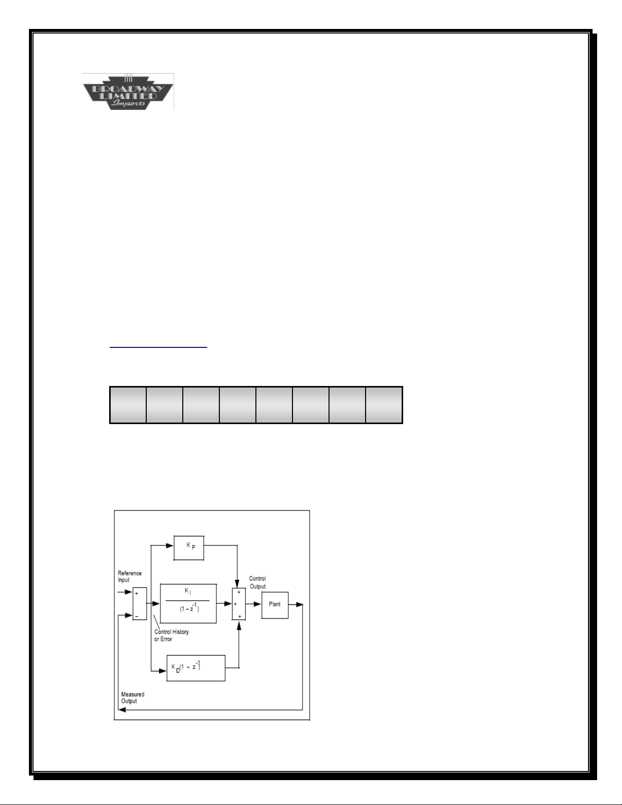
CV112-113
Kp
Description
The Proportional Gain of the Motor Controller
Values
0-32767
Initial Value
CV113=32; CV112=0
Related CVs
CV114—CV120
Bit 7 Bit 0
x x x x x x x x
CV113 is the MSB while CV112 is the LSB representing the PID
controller’s proportional gain.
84
Page 85
SYSTEM CVs
CV114-115
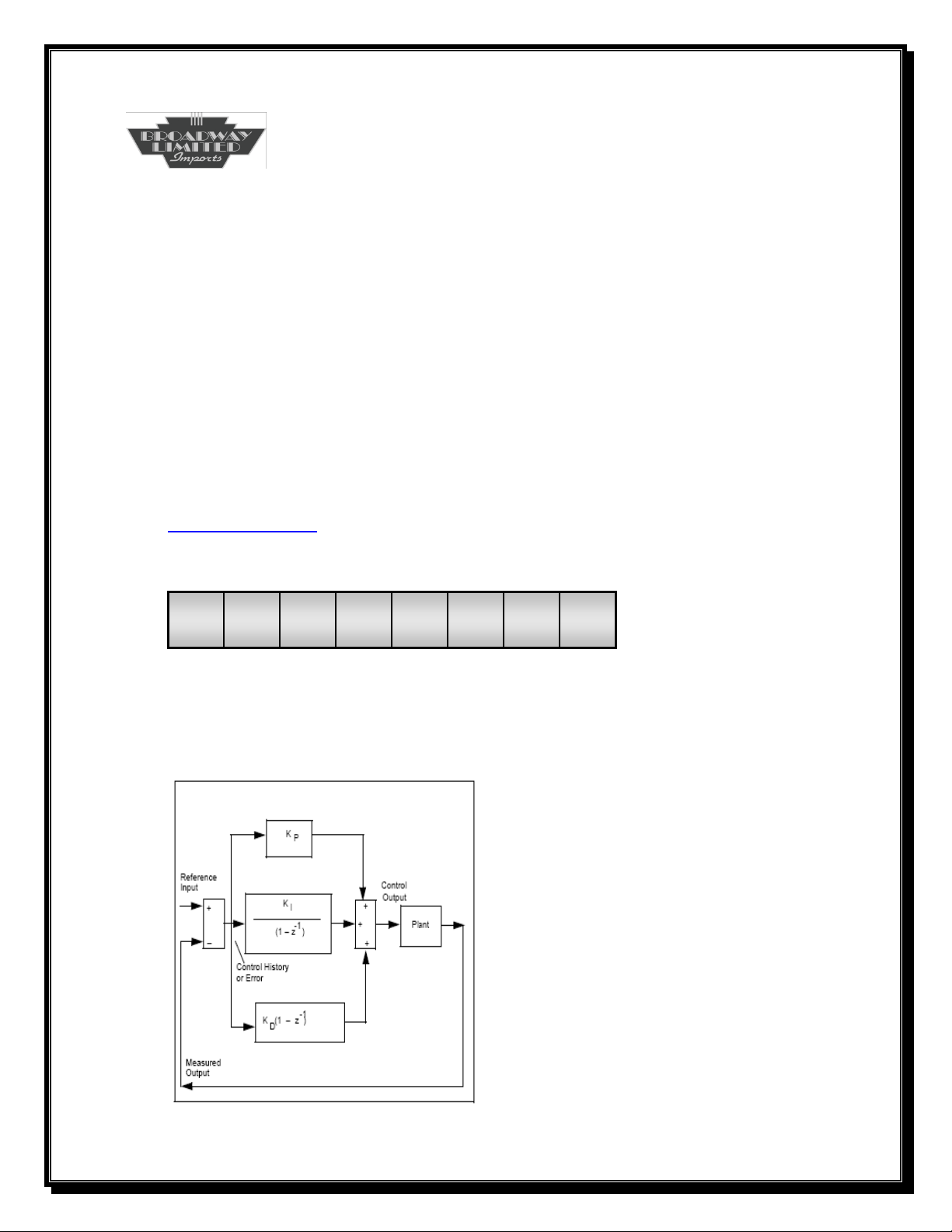
Ki
Description
The Integral Gain of the Motor Controller
Values
0-32767
Initial Value
CV115=1; CV114=50
Related CVs
CV112—CV120
Bit 7 Bit 0
x x x x x x x x
CV115 is the MSB while CV114 is the LSB representing the PID
controller’s integral gain.
85
Page 86
SYSTEM CVs
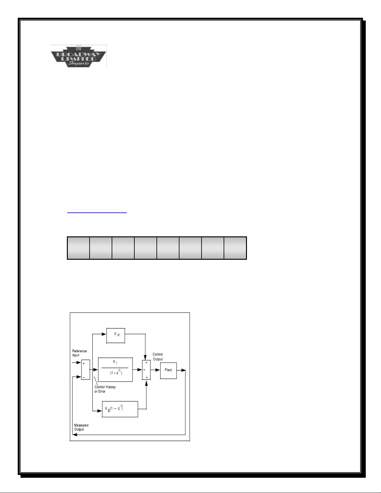
CV116-117
Kd
Description
The Derivative Gain of the Motor Controller
Values
0-32767
Initial Value
CV117=0; CV116=0
Related CVs
CV112—CV120
Bit 7 Bit 0
x x x x x x x x
CV117 is the MSB while CV116 is the LSB representing the PID
controllers proportional gain.
86
Page 87
SYSTEM CVs
CV118
KpSlow
Description
The Slow Speed Proportional Gain of the Motor Controller
Values
0-255
Initial Value
20
Related CVs
CV112—CV120
Bit 7 Bit 0
0 0 0 1 0 1 0 0
This value allows the locomotive to creep at very slow speeds.
Increasing this value increases the added torque at these very slow
speeds. Setting this value to zero disables the slow speed algorithm
and may cause the slow speed to become jerky or not run at all.
87
Page 88
SYSTEM CVs
CV120
Speed Step Smoothing
Description
This Value Controls a Smoothing Routine Designed to Interpolate
Motor Speeds in Between Large Changes
Values
1-255
Initial Value
25
Related CVs
CV3, CV4, CV245
Bit 7 Bit 0
0 0 0 1 1 0 0 1
Changing speed steps with backemf enabled creates a quick, fast
change of speed, which is not smooth. This parameter allows
interpolation between the speed steps, creating a very smooth effect.
This effect also adds momentum. It is recommended that CV3 and
CV4 be disabled while setting this feature. If additional momentum
is still needed, than adjust CV3 and CV4 as needed. A lower value
for CV120 creates a smoother change, but adds momentum. This CV
only functions in all speed step modes, DC as well as DCC. CV245
bit 5 may be cleared to disable Speed Step Smoothing.
88
Page 89
SYSTEM CVs
CV121
Consist Functions Type 2
Description
Determines Which Functions (F13-F20) are Allowed in the Consist
Values
0-255
Initial Value
255
Related CVs
CV19, CV21, CV22, CV122, CV229
Bit 7 Bit 0
F20 F19 F18 F17 F16 F15 F14 F13
The decoder responds to all functions that have a “1” set in this CV
once a consist is configured. A consist is configured by CV19
programmed to a value from 1-127. A value of 0 breaks the consist.
See CV19. This CV is used to configure the engine for a front, middle
or end in the consist.
An example for consist number 60:
CV19=60
Front Engine CV21=255 CV22=255 CV121=255 CV122=255 CV229=246
Middle Engine CV21=176 CV22=5 CV121=0 CV122=96 CV229=0
Rear engine CV21=176 CV22=5 CV121=0 CV122=96 CV229=2
See Consist Synopsis.
89
Page 90

Bit 7: 0=F20 Disabled
1=F20 Enabled
Bit 6: 0=F19 Disabled
1=F19 Enabled
Bit 5: 0=F18 Disabled
1=F18 Enabled
Bit 4: 0=F17 Disabled
1=F17 Enabled
Bit 3: 0=F16 Disabled
1=F16 Enabled
Bit 2: 0=F15 Disabled
1=F15 Enabled
Bit 1: 0=F14 Disabled
1=F14 Enabled
Bit 0: 0=F13 Disabled
1=F13 Enabled
90
Page 91
SYSTEM CVs
CV122
Consist Functions Type 3
Description
Determines Which Functions (F21-F28) are allowed in the Consist
Values
0-255
Initial Value
255
Related CVs
CV19, CV21, CV22, CV121, CV229
Bit 7 Bit 0
F28 F27 F26 F25 F24 F23 F22 F21
The decoder responds to all functions that have a “1” set in this CV
once a consist is configured. A consist is configured by CV19
programmed to a value from 1-127. A value of 0 breaks the consist.
See CV19. This CV is used to configure the engine for a front, middle
or end in the consist.
An example for consist number 60:
CV19=60
Front Engine CV21=255 CV22=255 CV121=255 CV122=255 CV229=246
Middle Engine CV21=176 CV22=5 CV121=0 CV122=96 CV229=0
Rear engine CV21=176 CV22=5 CV121=0 CV122=96 CV229=2
See Consist Synopsis.
91
Page 92

Bit 7: 0=F28 Disabled
1=F28 Enabled
Bit 6: 0=F27 Disabled
1=F27 Enabled
Bit 5: 0=F26 Disabled
1=F26 Enabled
Bit 4: 0=F25 Disabled
1=F25 Enabled
Bit 3: 0=F24 Disabled
1=F24 Enabled
Bit 2: 0=F23 Disabled
1=F23 Enabled
Bit 1: 0=F22 Disabled
1=F22 Enabled
Bit 0: 0=F21 Disabled
1=F21 Enabled
92
Page 93
SOUND CVs
CV130
Master Volume Sound Increment
Description
This Value is the Increment/Decrement Amount for Master Volume
Values
0 to 255
Initial Value
16
Related CVs
CV41, CV133, CV134
Bit 7 Bit 0
0 0 0 1 0 0 0 0
The decoder’s analog potentiometer (volume control) increases or
decreases the volume of the sound. The change between the 255
available steps may be set from 0 to 255. Every press of the volume
toggle switch will result in a volume change incrementing or
decrementing by this value.
93
Page 94
SOUND CVs
CV131
DC Sound Unit Startup (Turn-On) Voltage
Description
This Value Sets the Decoders DC Sound Turn-On Voltage
Values
0 to 255
Initial Value
72
Related CVs
CV130, CV132, CV133, CV134
Bit 7 Bit 0
0 1 0 0 1 0 0 0
The sound unit has a minimum power requirement necessary to play
all sound effects. Many factors contribute to what the necessary
voltage is such as the power source, the startup volume (CV133) and
system loading. Lowering this value will instruct the sound unit to
start the audio effects at a lower voltage.
Note: Care should be taken with this value. Lowering this value
too low will result in the unit not being able to function at all. If
this occurs, set this value to a larger number or the initial value and
reprogram the value in service mode.
94
Page 95
SOUND CVs
CV132
DC Sound Unit Shutdown (Turn-Off) Voltage
Description
This Value Sets the Decoders DC Sound Turn-Off Voltage
Values
0 to 255
Initial Value
58
Related CVs
CV130, CV131, CV133, CV134
Bit 7 Bit 0
0 0 1 1 1 0 1 0
The sound unit is instructed to play the shutdown effect and turn off
all effects at this value. The shutdown effect only plays from the idle
condition. Many factors contribute to what this actual voltage is such
as the power source, system volume, individual volumes (CV133,
CV135—CV156) and system loading. Lowering this value will
instruct the sound unit to play the shutdown effect at a lower voltage.
Note: Care should be taken with this value. Lowering this value
too low will result in the unit not being able to play the shutdown
effect and terminate all effects properly. The sound unit could
abruptly shut off. If this occurs, set this value to a larger number or
the initial value.
95
Page 96

SOUND CVs
CV133
Sound Unit Master Volume
Description
This Value Sets the Power Up Master Sound Effects Volume
Values
0 to 255
Initial Value
128
Related CVs
CV130, CV134
Bit 7 Bit 0
1 0 0 0 0 0 0 0
The decoder’s digital volume control increases or decreases the
volume of the sound. The change between the 255 available steps
may be set from 0 to 255 (CV130). Every press of the volume toggle
switch will result in a volume change incrementing or decrementing
by the value in CV130. This value (CV133) is the decoder’s power up
value. A higher value increases the volume while a lower value
decreases the volume.
96
Page 97
SOUND CVs
CV134
Sound Unit Maximum Volume
Description
This Value Sets the Maximum Sound Effects Volume
Values
0 to 255
Initial Value
128
Related CVs
CV130, CV133
Bit 7 Bit 0
1 0 0 0 0 0 0 0
The decoder’s digital volume control increases or decreases the
volume of the sound. The change between the 255 available steps
may be set from 0 to 255 (CV130). Every press of the volume toggle
switch will result in a volume change incrementing or decrementing
by the value in CV130. This value (CV134) is the decoder’s maximum
allowed value. A higher value allows a louder volume while a lower
value allows a quieter volume. Note that the initial value sets the
volume at 100%. Increasing this value allows the unit to be
overdriven and distortion may be heard.
97
Page 98
SOUND CVs
CV135
Horn Volume
Description
This Value Controls the Horn Sound Effects Volume
Values
0 to 255
Initial Value
128
Related CVs
CV35, CV133
Bit 7 Bit 0
1 0 0 0 0 0 0 0
The decoder’s horn sound effect volume is variable from 0 to 255. A
higher value increases the volume while a lower value decreases the
volume.
98
Page 99
SOUND CVs
CV136
Bell Volume
Description
This Value Controls the Bell Sound Effects Volume
Values
0 to 255
Initial Value
128
Related CVs
CV34, CV133
Bit 7 Bit 0
1 0 0 0 0 0 0 0
The decoder’s bell sound effect volume is variable from 0 to 255. A
higher value increases the volume while a lower value decreases the
volume.
99
Page 100
SOUND CVs
CV137
Diesel Volume
Description
This Value Controls the Startup, Rev Levels and Shutdown Sound
Effects Volume
Values
0 to 255
Initial Value
128
Related CVs
CV133
Bit 7 Bit 0
1 0 0 0 0 0 0 0
The decoder’s diesel engine sound effect volume is variable from 0 to
255. A higher value increases the volume while a lower value
decreases the volume. This value controls a group of sounds: diesel
startup, diesel rev levels and diesel shutdown sound effects.
100
 Loading...