

Page 1

Operating Instruction Manual
LCD MONITOR
Page 2

Contents
Important Safeguards ................................................................................ 2
FCC NOTICE ........................................................................................... 5
Unpacking ................................................................................................. 5
Service....................................................................................................... 5
Care and Maintenance............................................................................... 5
Model Designation .................................................................................... 6
Accessories ............................................................................................... 6
Certification .............................................................................................. 6
Installation................................................................................................. 6
Power Requirements ................................................................................. 7
Power Connection Procedure .................................................................... 7
Rear interface ............................................................................................ 8
Explanation of connectors......................................................................... 8
Testing the Monitor................................................................................... 9
Controls & Functions .............................................................................. 10
OSD Setup .............................................................................................. 11
Important Safeguards
1. Read Instructions - All the safety and operating instructions should be
read before the unit is operated.
2. Retain Instructions - The safety and operating instructions should be
retained for future reference.
3. Heed Warnings - All warnings on the unit and in the operating instructions
should be adhered to.
4. Follow Instructions - All operating and use instructions should be followed.
5. Cleaning - Unplug the unit from the outlet before cleaning. Do not use
liquid cleaners or aerosol cleaners. Use a damp cloth for cleaning.
6. Attachments - Do not use attachments not recommended by the product
manufacturer as they may cause hazards.
7. Accessories - Do not place this unit on an unstable stand, tripod, bracket,
or mount. The unit may fall, causing serious injury to a person and serious
damage to the unit. Use only with a stand, tripod, bracket, or mount
recommended by the manufacturer or sold with the product. Any mounting
of the unit should follow the manufacturer's instructions and should use a
mounting accessory recommended by the manufacturer.
An appliance and cart combination should be moved with care.
Quick stops, excessive force, and uneven surfaces may cause
the appliance and cart combination to overturn.
8. Ventilation - Openings in the enclosure, if any, are provided for ventilation,
to ensure reliable operation of the unit, and to protect it from overheating.
These openings must not be blocked or covered. This unit
should not be placed in a built-in installation unless proper ventilation is
provided or the manufacturer's instructions have been adhered to.
9. Power Sources - This unit should be operated only from the type of
power source indicated on the marking label. If you are not sure of the type
of power supply you plan to use, consult your appliance dealer or local
power company. For units intended to operate from battery power or other
sources, refer to the operating instructions.
10. Grounding or Polarization - This unit may be equipped with a polarized
alternating-current line plug (a plug having one blade wider than the other).
This plug will fit into the power outlet only one way. This is a safety feature.
If you are unable to insert the plug fully into the outlet, try reversing the plug.
If the plug should still fail to fit, contact your electrician to replace your
obsolete outlet. Do not defeat the safety purpose of the polarized plug.
Page 2
Page 1
Page 3
Alternatively, this unit may be equipped with a 3-wire grounding-type plug, a
plug having a third (grounding) pin. This plug will only fit into a groundingtype power outlet. This is a safety feature. If you are unable to insert the
plug into the outlet, contact your electrician to replace your obsolete outlet.
Do not defeat the safety purpose of the grounding-type plug.
11. Power Cord Protection - Power supply cords should be routed so that
they are not likely to be walked on or pinched by items placed upon or
against them, paying particular attention to cords and plugs, convenience
receptacles, and the point where they exit from the appliance.
12. Power Lines - An outdoor system should not be located in the vicinity of
overhead power lines or other electric light or power circuits or where it can
fall into such power lines or circuits. When installing an outdoor system,
extreme care should be taken to keep from touching such power lines or
circuits as contact with them might be fatal. U.S.A. models only - refer to the
National Electrical Code Article 820 regarding installation of CATV systems.
13. Overloading - Do not overload outlets and extension cords as this can
result in a fire or electric shock.
14. Object and Liquid Entry - Never push objects of any kind into this unit
through openings, as they may touch dangerous voltage points or short out
parts that could result in a fire or electric shock. Never spill liquid of any kind
on the unit.
15. Servicing - Do not attempt to service this unit yourself as opening or
removing covers may expose you to dangerous voltage or other hazards.
Refer all servicing to qualified service personnel.
16. Damage Requiring Service - Unplug the unit from the outlet and refer
servicing to qualified service personnel under the following conditions:
a. When the power supply cord or plug is damaged.
b. If liquid has been spilled or objects have fallen into the unit.
c. If the unit has been exposed to rain or water.
d. If the unit does not operate normally by following the operating
instructions. Adjust only those controls that are covered by the operating
instructions, as an improper adjustment of other controls may result in
damage and will often require extensive work by a qualified technician
to restore the unit to its normal operation.
e. If the unit has been dropped or the cabinet has been damaged.
f. When the unit exhibits a distinct change in performance--this indicates
a need for service.
17. Replacement Parts - When replacement parts are required, be sure the
service technician has used replacement parts specified by the
manufacturer or have the same characteristics as the original part.
Unauthorized substitutions may result in fire, electric shock, or other
hazards.
18. Safety Check - Upon completion of any service or repairs to this unit,
ask the service technician to perform safety checks to determine that the
unit is in proper operating condition.
19. Coax Grounding - If an outside cable system is connected to the unit, be
sure the cable system is grounded. U.S.A. models only--Section 810 of the
National Electrical Code, ANSI/NFPA No.70-1981, provides information with
respect to proper grounding of the mount and supporting structure,
grounding of the coax to a discharge unit, size of grounding conductors,
location of discharge unit,connection to grounding electrodes, and
requirements for the grounding electrode.
20. Lightning - For added protection of this unit during a lightning storm, or
when it is left unattended and unused for long periods of time, unplug it from
the wall outlet and disconnect the cable system. This will prevent damage to
the unit due to lightning and power line surges.
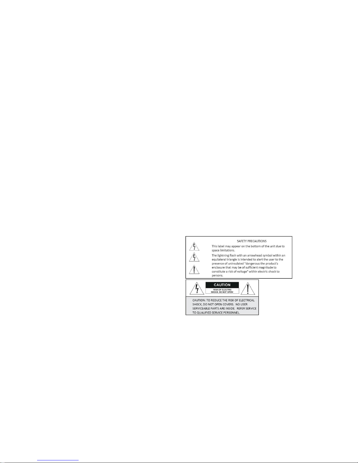
The following labels may appear on the product. An explanation of the
symbols used is as follows:
Page 4
Page 3
Page 4

FCC NOTICE
This equipment generates and uses radio frequency energy and if not
installed and used properly, that is, in strict accordance with the
manufacturer's instructions, may cause interference to radio and television
reception. It has been type tested and found to comply with the limits for a
Class B computing device in accordance with Part 15 of FCC Rules, which
are designed to provide reasonable protection against such interference in a
residential installation. However, there is no guarantee that interference will
not occur in a particular installation. If this equipment does cause
interference to radio or television reception, which can be determined by
turning the equipment off and on, the user is encouraged to try to correct
the interference by one or more of the following measures:
Relocate the monitor away from the TV/radio receiver.
Plug the monitor into a different wall outlet so that the console is on a
different branch circuit.
Re-orient the TV/radio antenna.
If necessary, the user should consult the dealer or an experienced
radio/television technician for additional suggestions.
Note: Changes or modifications to the unit may void FCC Certification.
Unpacking
Unpack carefully. This is electromechanical equipment and should be
handled with care. If an item appears to have been damaged in shipment,
replace it properly in its carton and notify the shipper. If any items are
missing, notify the manufacturer. The shipping carton is the safest
container in which the unit may be transported. Save it for possible future
use.
Service
If the unit ever needs repair service, the customer should contact the
manufacturer for a Return of Materials Authorization (RMA) and shipping
instructions.
Care and Maintenance
Perform routine maintenance to keep the unit dust free. Clean the screen
as needed using appropriate cleaning fluid and soft, non-abrasive towels.
Unplug the monitor before cleaning.
Model Designation
Compare product description on the unit’s label to determine which unit
from the below list applies to your product.
BSM-19P 19” LCD Monitor with LED Backlight, 1280x1024, BNC,
VGA, HDMI, Audio. 12VDC ± 10%, <18W
BSM-22P 22” LCD Monitor with LED Backlight, 1920x1080, BNC,
VGA, HDMI, Audio, 12VDC ± 10%, <25W
Accessories
Please check for the following listed accessories before installation:
- VGA cable
- User manual
- AC Adapter
Certification
Installation should be performed by a licensed professional and conform to
the National Electrical Code (NEC) and any applicable local codes.
Installation
Remove the unit from its packaging. The monitor’s connectors are located
on the rear of the unit. Mounting holes are provided to attach the monitor to
monitor mounts compatible with the VESA 100mm x 100mm hole pattern.
Use M4x8mm screws with the selected mount Carefully read the
instructions included with the mount to properly secure the monitor to the
mount. Always use appropriate fasteners with sufficient strength to support
the monitor. Do not install these units outdoors, near large machinery, in
hot areas, or areas with high humidity.
Page 6
Page 5
Page 5
Power Requirements
When selecting a power supply, match the supply’s voltage output to the
monitor (details below). Ensure the supply’s maximum output (Amps or
Watts) is sufficient to power the device(s) connected to it (refer to Model
Designation section for device wattage).
19” and 22” Monitor
Nominal voltage: DC12V
Operating voltage range: DC 10.8 ~ 13.2 Volts
Power Connection Procedure
Review and follow the below procedure before connecting the monitor to a
power source. Refer to the prior section to determine a monitor’s nominal
voltage and operating voltage range.
Check the polarity of the power connector before plugging in the
monitor. The internal portion of the connector is positive (+) and the
outside, or “shell” is negative (-).
Non-adjustable power supplies: measure the voltage at the
monitor before connecting the supply to the monitor to ensure it is
within the PVM’s operating voltage range stated above. If the
voltage is too high, consider using extra cable to lower the voltage,
or select a different power supply. Measure the voltage again while
the monitor is on to confirm the voltage remains within the operating
range. If the voltage is too low, try plugging the supply in closer to
the monitor and use a shorter power cable, or selecting a different
power supply.
Unregulated adjustable power supplies: measure the voltage at
the monitor before connecting the supply to the monitor to ensure it
is within the PVM’s operating voltage range stated above. Measure
the voltage again while the monitor is on to confirm the voltage
remains within the operating range. Adjust the power supply in 0.5
Volt increments until the voltage read at the monitor, under load
(monitor on), is within the operating voltage range.
Regulated adjustable power supplies: set the power supply to
output the monitor’s nominal voltage and measure the voltage at the
monitor under load (while monitor is on) to confirm the voltage is
within the above stated tolerance.
Powering multiple monitors from a single power supply: shorter
cables will produce a higher voltage at the monitor than longer
cables. Test the voltage before and after connecting a monitor to
ensure the voltage supplied to the monitor is within the operating
voltage range stated above.
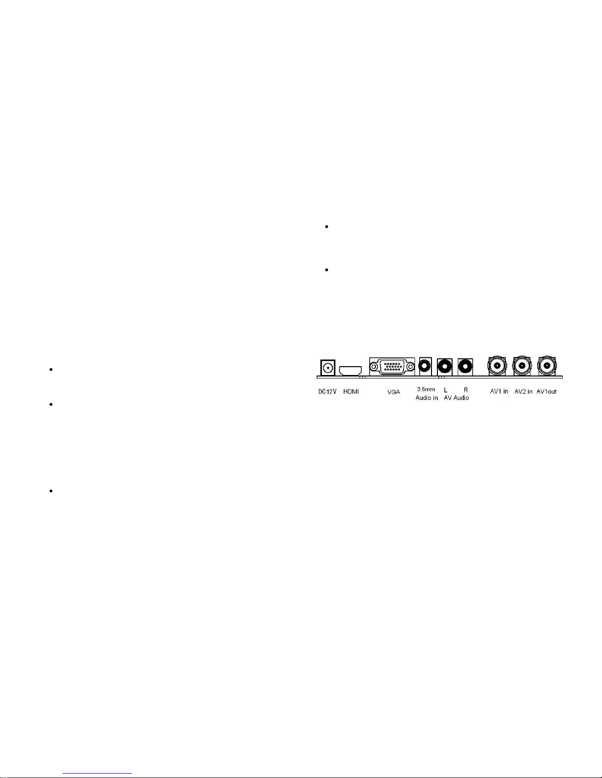
Rear interface
Explanation of connectors
This section describes the jacks on the back panel of your MONITOR.
There are several ways to connect devices.
DC12V: DC barrel plug connector for 12VDC power supply.
HDMI Lets you connect a device, such as a digital cable box, with an HDMI
or a DVI output. Devices with a DVI output can be viewed through this
monitor’s HDMI port using a DVI-to-HDMI adapter plug (not included).
VGA Connect a computer or other device with a VGA output to this port
using a VGA cable with a 15 pin D-sub connector. Note that VGA
carries a video signal only (no audio).
Page 8
Page 7
Page 6
AV IN/OUT: The “AV In” connector lets you connect a device that has
composite video output, such as a VCR or DVD player, to be displayed
on the monitor. The “AV Out” connector duplicates the external input to
create a “loop out” to another device such as a DVR.
AUDIO IN (Stereo mini jack) For use when supplying video through a VGA
cable. Audio can be input using the 3.5 mm stereo mini pin cable
(sometimes referred to as 1/8” stereo mini pin) to connect an audio
source to the monitor.
AUDIO L and R: For use when supplying video through the AV IN or S-
Video connectors. Receives audio from another device such as a
camcorder, video game console, VCR, or DVD player. The left audio
connector is typically white. The right audio connector is usually red.
Testing the Monitor
After connection, turn on the power switch located on the rear(or side)
bezel. Before you test your monitor, make sure the desired cable is
connected properly.. To test that the monitor is working properly:
1. Turn on your video source device (computer, DVR, etc.). Check that
the source device is outputting the correct resolution
(19”: 1280 x 1024 or 22”: 1920x1080).
2. The image on the monitor should be displayed. If it is not, ensure the
LED is blue – red indicates power but no signal.
3. Make sure the video image is centered within the screen area. Use
the monitor controls to adjust the image, if necessary. Perform an
Auto Config first, then if you wish you can adjust the horizontal and
vertical position, contrast, and brightness to better suit your video
card and your personal preference. Refer to Basic OSD setup for
more information on using the on-screen menu to adjust the video
display.
Controls & Functions
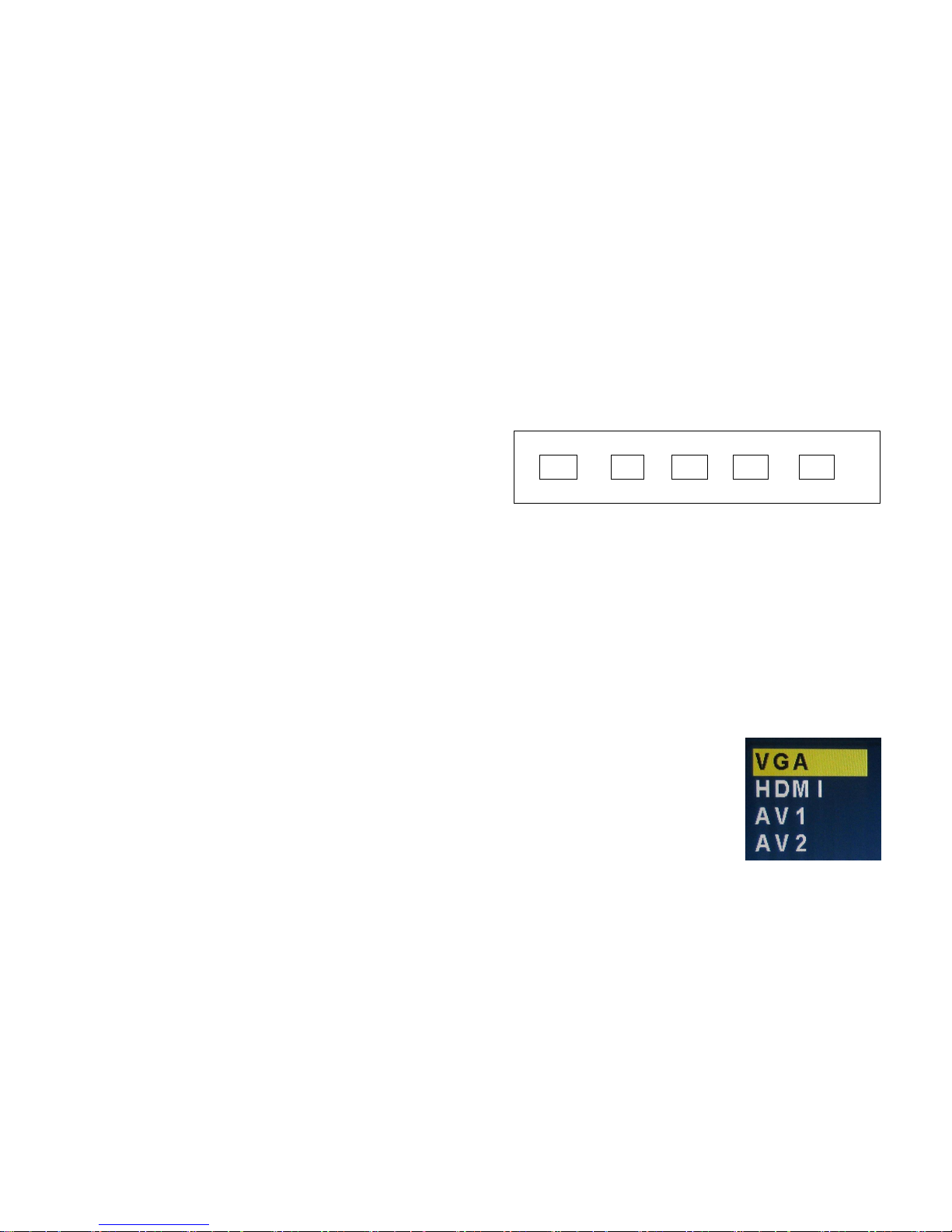
Ⅰ、Buttons on the lower-right part of the panel
The buttons shown in the diagram are located on the lower-right part of the
monitor case on the side. If you cannot locate your remote, you can use
these buttons to operate many of the monitor’s features.
SOURCE MENU + - POWER
1.POWER Turn on / off the monitor
2.SOURCE: Accesses the available video input signals
(VGA、HDMI AV1、AV2)
3.MENU: Brings up the MONITOR Main menu. When in the OSD
system, press MENU button to return to the previous menu or exit
4.+(Plus): turn on the volume. In the MONITOR menu system, acts like
the right arrow button on the remote control and adjusts menu
controls.
5.- (Minus):turn down the volume. In the MONITOR menu system,
acts like the left arrow button on the remote control and adjusts
menu controls.
Choose the input source
Press source button on the monitor or remote
control to display the Source menu. Press
Source again to select the desired input,
then press“ +/- (>)” to switch to it
Page 10
Page 9
Page 7
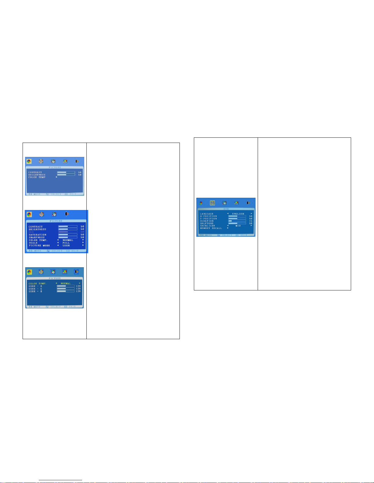
OSD Setup
Picture (VGA)
Picture (AV)
Color temp.
Brightness: Adjust the brightness of the
picture. (Adjustment range:0-100)
Contrast: Adjust the difference between
the light and dark areas of the picture.
(Adjustment range:0-100)
Saturation (AV/HDMI): Adjust color
saturation (Adjustment range 0-100)
Sharpness (AV/HDMI): Adjust image
sharpness (Adjustment range 0-100)
Scale (AV/HDMI): Scale composite image
to Full-screen, Normal, or Center
Picture Mode (AV/HDMI): Select between
preset picture modes (User, Standard,
Soft, Vivid)
Color temp: press“+”button to select
between different color intensity presets
(Normal,.Warm, Cool, s-RGB), or select
User to define the Red/Green/Blue color
intensities.
USER:
USER-R : 0~255
USER-G : 0~255
USER-B : 0~255
Note: Functions denoted “AV/HDMI” are
only available with composite inputs
(BNC) or HDMI.
.
OSD
Language: Select your preferred
language for the menus: (English.
Chinese. German. French. Spanish.
Portuguese. Russian. Italian)
H-Position: H-position moves the OSD
position left (0-50) or pressing the “>
“ button. H-position moves the OSD
position right (51-100)
V-Position: Adjust the OSD image
vertically by pressing the “< or >
“ button.V-position moves the OSD
position up or down. 0-100
Duration: Adjust the OSD dwell time from
5-60 seconds.
Halftone: Replace color gradients in the
menu with small dots to simulate the
effect. Adjust from 0-50 to increase this
effect.
Back light: HIGH, MID. LOW
MEM-RECALL:press > key to reset to
the factory defaults
Page 12
Page 11
Page 8
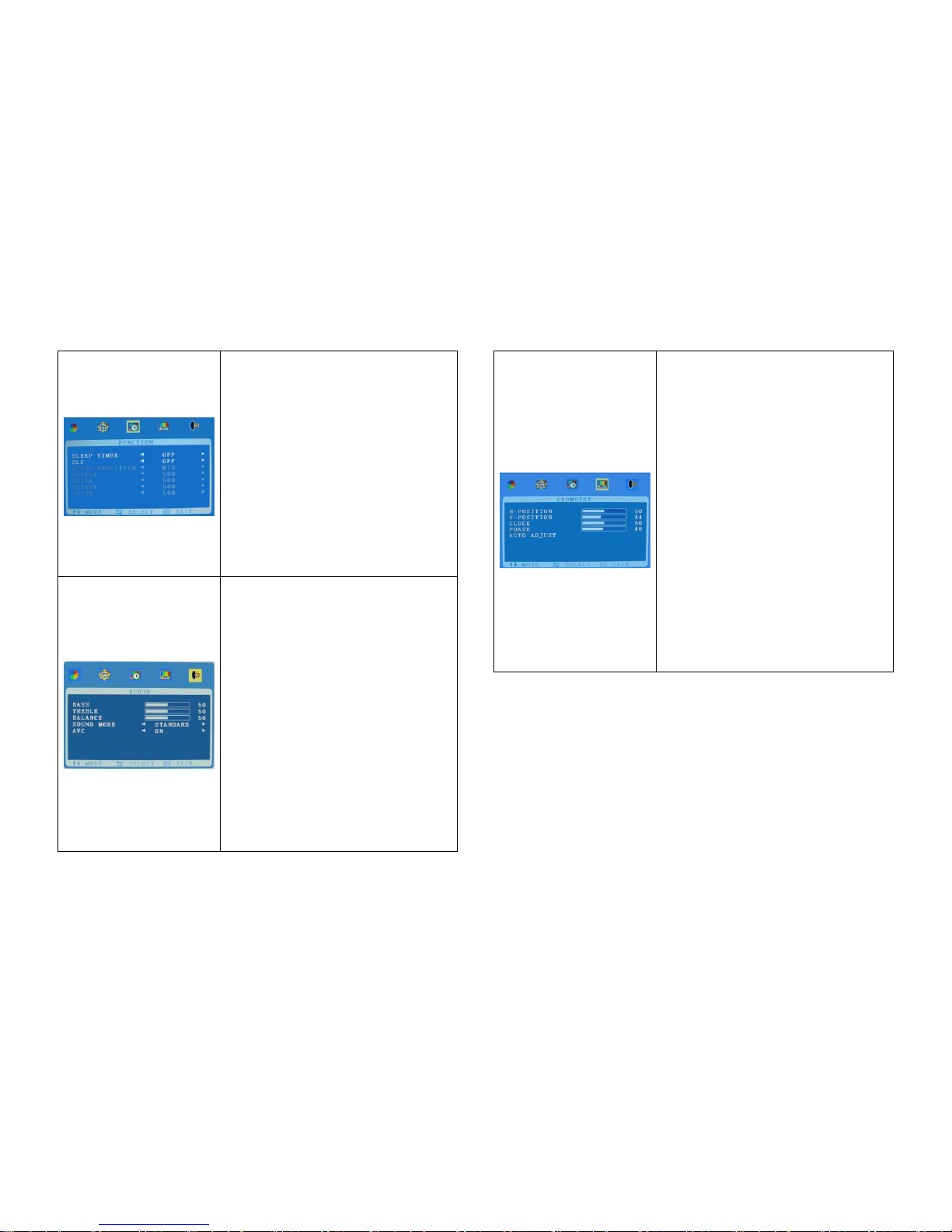
FUNCTION
Sleep-timer: Lets you set the monitor to
turn off after a given amount of time
(OFF .15min.30min.45min.60min)
DLC (Dynamic Luminance Control): ON /
OFF
NOISE REDUCTION:
Function available for AV inputs only.
Select Off, Low, High
HSTART、HSIZE、VSTART、VSIZE:
Function available for AV inputs only
Adjust the OSD image size/location.
Audio
BASS- Adjustment range:0-100
TREBLE- Adjustment range:0-100
Balance Adjusts how much audio is sent
to the left and right(-50 to +50). The
default value is 0. Adjusting the setting
towards -50 or +50 increases the volume
of one speaker or the other (R/L).
Sound Mode Provides special
processing through your speakers
(depending on the setting you chose as
your Sound Type). The available audio
modes are: Standard. User. movie. music.
AVC: Automatic Volume Control ON OFF
GEOMETRY
H-POSITION: Moves image horizontally
on-screen left (-) or right (+)
V-POSITION: Moves image vertically on-
screen up (+) or down (-).
CLOCK:If the clock setting of your image
is not fine-tuned, you may observe
periodic vertical bars of video noise on
your image. These bars of noise are
usually adjusted out when an Auto
Configuration is performed. If the bars of
noise are still present, this setting can be
adjust manually.
PHASE: Adjust this setting if unstable
horizontal lines appear in the image.
AUTO ADJUST: Press “+” or “-“ to
perform automatic configuration of the
Phase, Clock, Vertical and Horizontal
Position.
Page 14
Page 13
 Loading...