

Page 1
Quick Installation Guide
9400-8i8e Tri-Mode Host Bus Adapter
Hardware Installation Instructions
To install the Tri-Mode HBA, follow these steps:
1. Unpack the adapter, and inspect it for damage. Unpack the adapter in a static-free environment.
Remove the adapter from the antistatic bag, and carefully inspect the device for damage. If you notice
any damage, contact a Broadcom
ATTENTION: To avoid the risk of data loss, back up your data before you change your system
configuration.
2. Prepare the computer. Turn off the computer, and disconnect the power cord from the rear of the
power supply.
Thank you for purchasing the Host
Bus Adapter (HBA). Please take a few
minutes to read this quick
installation guide before you install
the HBA.
AT TE N TI O N: Perform all installation work at
an electrostatic discharge (ESD)safe workstation that meets the
requirements of EIA-625.
Requirements for Handling
Electrostatic Discharge Sensitive
. You must perform all
Devices
actions in accordance to the
latest revision of the IPC-A-610
ESD-recommended practices.
CAUTION: Disconnect the computer from the power supply and from any networks to which you
will install the adapter, or you risk damaging the system or experiencing electrical
shock.
3. Remove the cover from the chassis.
4. Check the mounting bracket on the adapter (system dependent). If required for your system,
replace the full-profile mounting bracket that ships on the adapter with the low-profile bracket supplied.
Complete the following steps to attach the low-profile bracket.
a. Using a No.1 Phillips screwdriver that is ESD safe, remove the two Phillips screws that connect
the full-profile bracket to the board. Unscrew the two screws located at the top and bottom edges
of the board. Avoid touching any board components with the screwdriver or bracket.
b. Remove the full-profile bracket. Do not damage the adapter.
c. Place the adapter on top of the low-profile bracket. Position the bracket so that the screw holes
in the tabs align with the openings in the board.
d. Using a No.1 Phillips torque screwdriver that is ESD safe, set it to a maximum torque of 4.8 ±
0.5 inch-pounds. Replace the two Phillips screws removed in step a.
®
representative or your reseller sales and support representative.
ATTENTION: Exceeding this torque specification can damage the board, connectors, or screws, and can
void the warranty on the board.
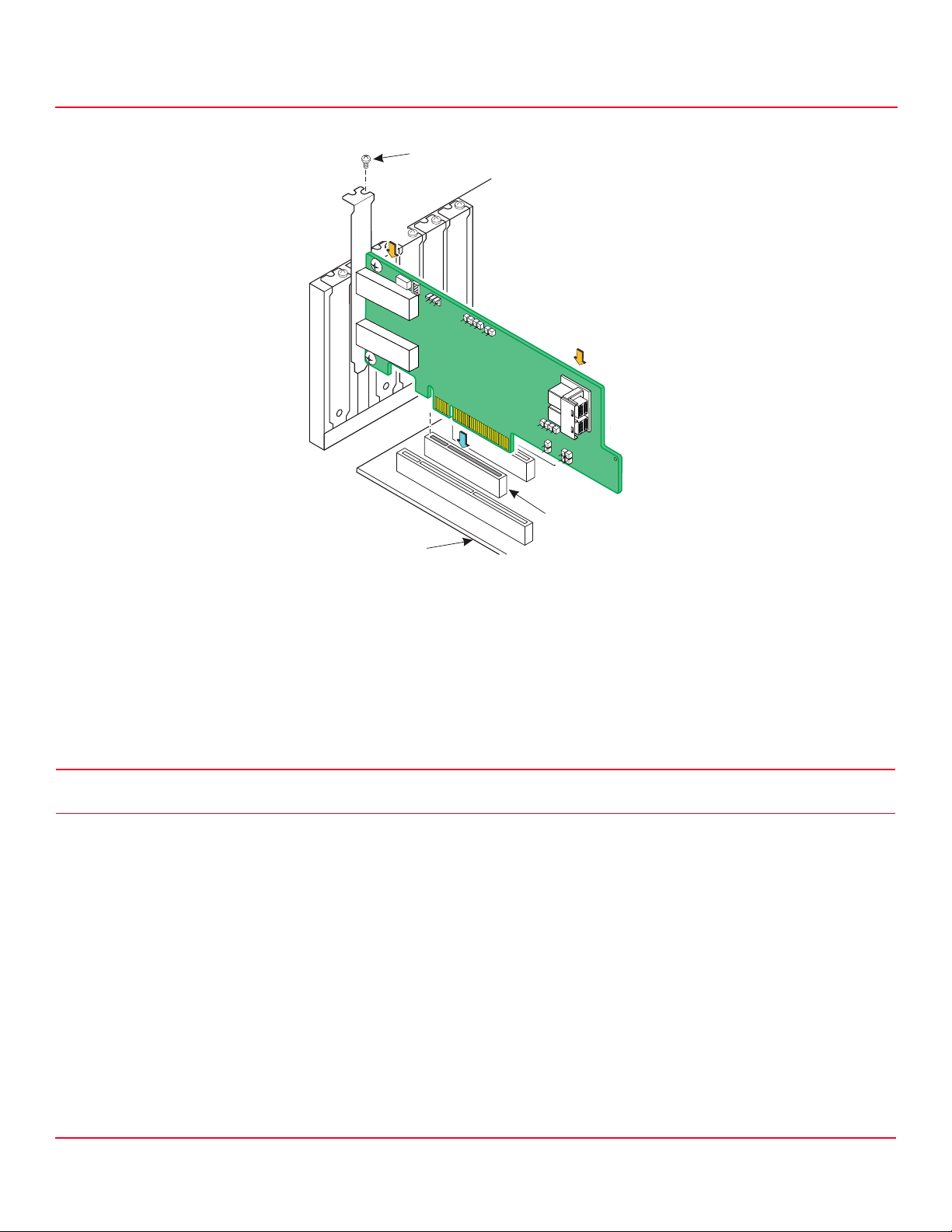
5. Insert the adapter into an available PCIe slot. Locate an empty x8 PCIe slot adequate for your
board. Remove the blank bracket panel on the rear of the computer that aligns with the empty PCIe slot.
Save this bracket screw, if applicable. Align the adapter to a PCIe slot. Press down gently, but firmly, to
seat the adapter correctly in the slot. The following figure shows how to insert the adapter into a PCIe
slot.
NOTE: The shape, size, and locations of the components on your adapter and its bracket might vary
from this illustration. The adapter requires an x8 PCIe slot.
Page 2
9400-8i8e Tri-Mode Storage Adapter QIG
Edge of Motherboard
PCIe Slot
Bracket Screw
Press Here
Press Here
3_03254
August 31, 2017
Figure 1 Install the 9400-8i8e Tri-Mode HBA in a PCIe Slot
Hardware Installation Instructions
6. Connect the cables between the adapter and the mid-plane or storage devices. The 9400-8i8e Tri-Mode HBA has two SFF-8643 internal x4 mini-
SAS HD connectors and two SFF-8644 external x4 mini-SAS HD connectors.
• For SAS/SATA connections, connect standard 12Gb/s SAS cables with internal or external mini-SAS HD connectors on one end to the adapter and
the appropriate connector on the other end to attach to the backplane, enclosure, or SAS/SATA devices.
• For PCIe/NVMe connections, use the appropriate U.2 enabler cable to enable connection to the backplane connectors, as shown in the following
figure. The U.2 enabler cable routes the REFCLK, sidebands, and PCIe signals to the appropriate pins on the backplane connector. Different U.2
enabler cables are available, depending on the backplane connector type. Using standard 12Gb/s SAS cables for NVMe connections might result in
damage to the PCIe adapter or the drive. For more information, refer to the Storage Adapter Cable Guide and the Broadcom MegaRAID
®
and HBA Tri-
Mode Storage Adapters User Guide at http://www.broadcom.com/support/download-search.
CAUTION: For NVMe connections to an SFF-8639 (U.2) bay or connections to a PCIe switch, use only approved cables with REFCLK forwarded on
the proper pins. Improperly connecting a standard 12Gb/s SAS cable to an SFF-8639 bay can damage the adapter and the drive.
Broadcom
Page 3

9400-8i8e Tri-Mode Storage Adapter QIG
9400-8i8e
.6-EX3LOT
.6-EX3LOT
0
0
?
August 31, 2017
Hardware Installation Instructions
Figure 2 9400-8i8e Tri-Mode HBA Connecting by U.2 Enabler Cable to Backplane Connectors
Each leg of the U.2 enabler cable must connect to adjacent drives; otherwise, the LEDs might not work properly. It does not matter which leg of the cable is
plugged into which connector pair as long as adjacent pairs are used. For more information on NVMe LED functionality, refer to the Broadcom MegaRAID and
HBA Tri-Mode Storage Adapters User Guide.
NOTE: NVMe (PCIe) connections are only supported using the internal ports.
7. Make sure that the system provides the required airflow for the adapter. Airflow must be at least 200 linear feet per minute (LFM) at 55°C inlet
temperature to avoid operating the board components above their maximum rated junction temperatures.
8. Replace the cover, reconnect any cords and cables, and power up the system. Replace the chassis’s cover, reconnect any power cords, and
reconnect any network cables. Turn on the power.
9. Install drivers and check for updates. Broadcom routinely post updates for firmware, drivers, and utilities. Check for the latest updates on the support
and download center, http://www.broadcom.com/support/download-search
The default firmware loaded on the adapter enables connections to SAS, SATA, and PCIe (NVMe) storage devices.
For more information on connecting SAS, SATA, and PCIe (NVMe) storage devices to the adapter, refer to the Broadcom MegaRAID and HBA Tri-Mode Storage
Adapters User Guide at http://www.broadcom.com/support/download-search.
The hardware installation of your Tri-Mode HBA is complete.
Broadcom
Page 4

TECHNICAL SUPPORT
For assistance installing, configuring, or running
the HBA, contact Broadcom Technical Support:
Website:
www.broadcom.com
WARRANTY NOTICE
1. The warranty does not cover the return of
parts damaged by changing the bracket.
2. The warranty does not cover ESD damage to
the HBA. HBAs returned without a bracket
mounted on the board will be returned without
return merchandise authorization (RMA)
processing.
Broadcom, the pulse logo, Connecting everything, Avago Technologies, Avago, and the A logo, and MegaRAID are among
the trademarks of Broadcom in the United States, certain other countries and/or the EU. Any other trademarks or trade
names mentioned are the property of their respective owners.
Copyright © 2017 Broadcom. All Rights Reserved.
The term "Broadcom" refers to Broadcom Limited and/or its subsidiaries. For more information, please visit
www.broadcom.com.
Broadcom reserves the right to make changes without further notice to any products or data herein to improve reliability,
function, or design.
Information furnished by Broadcom is believed to be accurate and reliable. However, Broadcom does not assume any
liability arising out of the application or use of th is information, nor the application or use of any product or circuit described
herein, neither does it convey any license under its patent rights nor the rights of others.
Corporate Headquarters Website
San Jose, CA www.broadcom.com
Pub Number: 9400-8i8e-IG100
August 31, 2017.
 Loading...