

Page 1

Broadcom® NetXtreme® BCM57XX User
Guide
Last revised: March 2015
INGSRV170-CDUM100-R
Page 2

NetXtreme User Guide
Information in this document is subject to change without notice.
© 2015 Broadcom Corporation. All rights reserved.
This document is protected by copyright and is distributed under licenses restricting its use, copying, distribution, and
decompilation. No part of this document may be reproduced in any form by any means without prior written authorization of
Broadcom Corporation. Documentation is provided as is without warranty of any kind, either express or implied, including
any kind of implied or express warranty of non-infringement or the implied warranties of merchantability or fitness for a
particular purpose.
Broadcom Corporation reserves the right to make changes without further notice to any products or data herein to improve
reliability, function, or design. Information furnished by Broadcom Corporation is believed to be accurate and reliable.
However, Broadcom Corporation does not assume any liability arising out of the application or use of this information, nor
the application or use of any product or circuit described herein, neither does it convey any license under its patent rights or
the rights of others.
Broadcom, the pulse logo, Connecting everything, the Connecting everything logo, NetXtreme, Ethernet@Wirespeed,
LiveLink, and Smart Load Balancing are among the trademarks of Broadcom Corporation and/or its affiliates in the United
States, certain other countries, and/or the EU. Microsoft and Windows are trademarks of Microsoft Corporation. Linux is a
trademark of Linus Torvalds. Intel is a trademark of Intel Corporation. Magic Packet is a trademark of Advanced Micro
Devices, Inc. Red Hat is a trademark of Red Hat, Inc. PCI Express is a trademark of PCI-SIG. Any other trademarks or trade
names mentioned are the property of their respective owners.
Last revised: March 2015
INGSRV170-CDUM100-R
Document INGSRV170-CDUM100-R Page 2
Page 3

NetXtreme User Guide
Table of Contents
Section 1: Installing the Hardware .................................................................................. 11
Safety Precautions .....................................................................................................................................11
Preinstallation Checklist ............................................................................................................................12
Installing the Adapter ................................................................................................................................. 12
Connecting the Network Cables................................................................................................................ 13
Copper................................................................................................................................................... 13
Section 2: Functionality and Features ........................................................................... 14
Functional Description............................................................................................................................... 14
Features....................................................................................................................................................... 14
Power Management ....................................................................................................................... 15
Adaptive Interrupt Frequency ......................................................................................................... 15
Dual DMA Channels.......................................................................................................................15
ASIC with Embedded RISC Processor .......................................................................................... 15
Broadcom Advanced Control Suite ................................................................................................ 16
Supported Operating Environments......................................................................................................... 16
Network Link and Activity Indication........................................................................................................ 16
Section 3: Windows Driver and Management Application Installation ........................ 17
Installing the Driver Software .................................................................................................................... 18
Using the Installer..................................................................................................................................18
Using Silent Installation .........................................................................................................................18
Modifying the Driver Software................................................................................................................... 19
Repairing or Reinstalling the Driver Software ......................................................................................... 20
Removing the Device Drivers .................................................................................................................... 20
Viewing or Changing the Properties of the Adapter ...............................................................................21
Setting Power Management Options ........................................................................................................ 21
Configuring the Communication Protocol To Use With BACS4 ............................................................ 22
Using WS-MAN ..................................................................................................................................... 22
WS-MAN Windows Server Configuration.......................................................................................22
WS-MAN Windows Client Installation ............................................................................................29
Using WMI ............................................................................................................................................. 31
Broadcom Corporation
Page 3 Document INGSRV170-CDUM100-R
Page 4

NetXtreme User Guide
Step 1: Set up Namespace Security Using WMI Control............................................................... 31
Step 2: Grant DCOM Remote Launch and Activate Permission.................................................... 31
Special Configuration for WMI on Different Systems..................................................................... 32
Section 4: Linux Driver and Management Application Installation ..............................33
Packaging ................................................................................................................................................... 33
Installing TG3 Driver Software .................................................................................................................. 34
Installing the Source RPM Package ..................................................................................................... 34
Building the Driver from the Source TAR File ....................................................................................... 35
Network Installations ................................................................................................................................. 35
Unloading/Removing the TG3 Driver........................................................................................................ 35
Unloading/Removing the Driver from an RPM Installation.................................................................... 35
Removing the Driver from a TAR Installation........................................................................................ 36
Driver Messages......................................................................................................................................... 36
Teaming with Channel Bonding................................................................................................................ 36
Linux Management Application Installation ............................................................................................ 37
Overview ............................................................................................................................................... 37
Communication Protocols.............................................................................................................. 37
Installing WS-MAN or CIM-XML on Linux Server ................................................................................. 38
Step 1: Install OpenPegasus ......................................................................................................... 38
Step 2: Start CIM Server on the Server ......................................................................................... 40
Step 3: Configure OpenPegasus on the Server ............................................................................ 40
Step 4: Install Broadcom CMPI Provider ....................................................................................... 41
Step 5: Perform Linux Firewall Configuration, If Required............................................................. 42
Step 6: Install BACS and Related Management Applications........................................................ 42
Installing WS-MAN or CIM-XML on Linux Client................................................................................... 43
Configure HTTPS on Linux Client.................................................................................................. 43
Installing the Broadcom Advanced Control Suite..................................................................................45
Section 5: VMware Driver Software .................................................................................46
Packaging ................................................................................................................................................... 46
Drivers......................................................................................................................................................... 46
Download, Install, and Update Drivers.................................................................................................. 46
Driver Parameters................................................................................................................................. 46
Driver Parameters................................................................................................................................. 47
Driver Defaults ...................................................................................................................................... 47
Broadcom Corporation
Document INGSRV170-CDUM100-R Page 4
Page 5

NetXtreme User Guide
Driver Messages.................................................................................................................................... 48
Section 6: Using Broadcom Advanced Control Suite 4................................................. 49
Broadcom Advanced Control Suite Overview .........................................................................................49
Starting Broadcom Advanced Control Suite ...........................................................................................50
BACS Interface............................................................................................................................................ 50
Explorer View Pane ............................................................................................................................... 51
Context View Selector ...........................................................................................................................52
Filter View....................................................................................................................................... 52
Context View Pane ................................................................................................................................ 52
Menu Bar ...............................................................................................................................................52
Description Pane ...................................................................................................................................53
Configuring Preferences in Windows....................................................................................................... 53
Connecting to a Host..................................................................................................................................54
Managing the Host......................................................................................................................................55
Information Tab: Host Information ......................................................................................................... 55
Managing the Network Adapter................................................................................................................. 57
Viewing Adapter Information .................................................................................................................57
Viewing Driver Information ....................................................................................................................59
Viewing Resource Information...............................................................................................................60
Viewing Hardware Information ..............................................................................................................61
Testing the Network............................................................................................................................... 62
Running Diagnostic Tests .....................................................................................................................63
Analyzing Cables ..................................................................................................................................64
Setting Adapter Properties ................................................................................................................... 65
Viewing Statistics ...................................................................................................................................... 67
General Statistics ...............................................................................................................................67
Configuring Teaming..................................................................................................................................68
Team Types .......................................................................................................................................... 69
Using the Broadcom Teaming Wizard .................................................................................................. 69
Using Expert Mode ............................................................................................................................... 82
Creating a Team ................................................................................................................................... 82
Modifying a Team ................................................................................................................................. 85
Adding a VLAN ..................................................................................................................................... 86
Viewing VLAN Properties and Statistics and Running VLAN Tests ..............................................87
Broadcom Corporation
Page 5 Document INGSRV170-CDUM100-R
Page 6

NetXtreme User Guide
Deleting a VLAN ........................................................................................................................... 87
Configuring LiveLink for a Smart Load Balancing and Failover and SLB (Auto-Fallback Disable)
Team...................................................................................................................................... 88
Saving and Restoring a Configuration .......................................................................................... 89
Viewing BASP Statistics ...................................................................................................................... 90
Configuring With the Command Line Interface Utility............................................................................ 91
Managing VLANs........................................................................................................................................ 92
Overview ............................................................................................................................................... 92
Adding VLANs to Teams....................................................................................................................... 93
Troubleshooting BACS.............................................................................................................................. 94
Section 7: Teaming ...........................................................................................................95
Overview ..................................................................................................................................................... 96
Load Balancing and Fault Tolerance........................................................................................................ 96
Types of Teams ............................................................................................................................. 96
Smart Load Balancing™ and Failover .................................................................................................. 97
Link Aggregation (802.3ad)................................................................................................................... 97
Generic Trunking (FEC/GEC)/802.3ad-Draft Static .............................................................................. 97
SLB (Auto-Fallback Disable) ................................................................................................................. 98
Limitations of Smart Load Balancing and Failover/SLB (Auto-Fallback Disable) Types of Teams....... 98
LiveLink™ Functionality ........................................................................................................................ 99
Teaming and Large Send Offload/Checksum Offload Support............................................................. 99
Section 8: Broadcom Gigabit Ethernet Teaming Services ..........................................100
Introduction .............................................................................................................................................. 101
Teaming Glossary ............................................................................................................................... 101
Teaming Concepts.............................................................................................................................. 102
Network Addressing..................................................................................................................... 102
Teaming and Network Addresses................................................................................................ 102
Description of Teaming Types ..................................................................................................... 103
Software Components ........................................................................................................................ 106
Hardware Requirements ..................................................................................................................... 107
Ethernet Switch............................................................................................................................ 107
Router .......................................................................................................................................... 107
Supported Features by Team Type .................................................................................................... 107
Selecting a Team Type ....................................................................................................................... 109
Broadcom Corporation
Document INGSRV170-CDUM100-R Page 6
Page 7

NetXtreme User Guide
Teaming Mechanisms .............................................................................................................................. 110
Architecture ......................................................................................................................................... 110
Outbound Traffic Flow ..................................................................................................................111
Inbound Traffic Flow (SLB Only) ..................................................................................................112
Protocol Support...........................................................................................................................112
Performance.................................................................................................................................113
Driver Support by Operating System................................................................................................... 114
Supported Teaming Speeds................................................................................................................ 115
Teaming and Other Advanced Networking Properties ........................................................................ 116
Checksum Offload ...............................................................................................................................117
IEEE 802.1p QoS Tagging .................................................................................................................. 117
Large Send Offload ............................................................................................................................. 117
Jumbo Frames.....................................................................................................................................117
IEEE 802.1Q VLANs ........................................................................................................................... 117
Wake on LAN ...................................................................................................................................... 118
Preboot Execution Environment (PXE) ...............................................................................................118
General Network Considerations............................................................................................................119
Teaming Across Switches ...................................................................................................................119
Switch-Link Fault Tolerance .........................................................................................................119
Spanning Tree Algorithm..................................................................................................................... 121
Topology Change Notice (TCN) ...................................................................................................122
Port Fast/Edge Port...................................................................................................................... 122
Teaming with Microsoft NLB/WLBS ....................................................................................................122
Application Considerations..................................................................................................................... 123
Teaming and Clustering—Microsoft Cluster Software......................................................................... 123
Teaming and Network Backup ............................................................................................................123
Load Balancing and Failover........................................................................................................ 124
Fault Tolerance ............................................................................................................................ 125
Troubleshooting Teaming Problems ......................................................................................................126
Teaming Configuration Tips ................................................................................................................126
Troubleshooting Guidelines................................................................................................................. 127
Frequently Asked Questions...................................................................................................................128
Event Log Messages ................................................................................................................................ 131
Windows System Event Log Messages ..............................................................................................131
Base Driver (Physical Adapter/Miniport).............................................................................................. 131
Broadcom Corporation
Page 7 Document INGSRV170-CDUM100-R
Page 8

NetXtreme User Guide
Intermediate Driver (Virtual Adapter/Team) ........................................................................................ 133
Section 9: iSCSI Protocol and Broadcom Boot Agent Software................................. 135
iSCSI Boot................................................................................................................................................. 135
Supported Operating Systems for iSCSI Boot .................................................................................... 135
iSCSI Boot Setup ................................................................................................................................ 135
Configuring the iSCSI Target ....................................................................................................... 135
Configuring iSCSI Boot Parameters ............................................................................................ 136
MBA Boot Protocol Configuration ................................................................................................ 137
iSCSI Boot Configuration............................................................................................................. 137
Enabling CHAP Authentication .................................................................................................... 140
Configuring the DHCP Server to Support iSCSI Boot.................................................................. 140
DHCP iSCSI Boot Configurations for IPv4................................................................................... 140
DHCP iSCSI Boot Configuration for IPv6 .................................................................................... 142
Configuring the DHCP Server................................................................................................... 142
Preparing the iSCSI Boot Image.................................................................................................. 143
Booting......................................................................................................................................... 146
Other iSCSI Boot Considerations ....................................................................................................... 146
Changing the Speed & Duplex Settings in Windows Environments ............................................ 146
Locally Administered Address ..................................................................................................... 146
Virtual LANs................................................................................................................................. 147
Troubleshooting iSCSI Boot................................................................................................................ 147
iSCSI Crash Dump ................................................................................................................................... 147
Broadcom Boot Agent Driver Software.................................................................................................. 148
Overview ............................................................................................................................................. 148
Setting Up MBA in a Client Environment ............................................................................................ 148
Configuring the MBA Driver ......................................................................................................... 148
Setting Up the BIOS .................................................................................................................... 150
Section 10: Manageability ..............................................................................................151
CIM............................................................................................................................................................. 151
SNMP......................................................................................................................................................... 152
BASP Subagent........................................................................................................................... 152
BASP Extensible-Agent ............................................................................................................... 152
Broadcom Corporation
Document INGSRV170-CDUM100-R Page 8
Page 9

NetXtreme User Guide
Section 11: User Diagnostics ........................................................................................ 154
Introduction...............................................................................................................................................154
System Requirements ..............................................................................................................................154
Running Broadcom NetXtreme User Diagnostics................................................................................. 155
Running in MS-DOS Command Prompt Mode.................................................................................... 155
Running in Broadcom Command Line Interface Mode........................................................................156
Diagnostic Test Descriptions .................................................................................................................. 158
Diagnostic Test Messages....................................................................................................................... 161
Section 12: Firmware Upgrade Utility ........................................................................... 164
Overview....................................................................................................................................................164
Installing the Firmware Upgrade Utility .................................................................................................. 164
Windows ..............................................................................................................................................164
Linux ....................................................................................................................................................164
Invoking the Utility....................................................................................................................................166
Windows.......................................................................................................................................166
Linux............................................................................................................................................. 167
Command Descriptions ........................................................................................................................... 169
cfg........................................................................................................................................................ 169
crc........................................................................................................................................................ 169
dev....................................................................................................................................................... 170
dir......................................................................................................................................................... 170
dumpnvram.......................................................................................................................................... 171
otpchk ..................................................................................................................................................171
prg .......................................................................................................................................................171
reset.....................................................................................................................................................171
restorenvram ....................................................................................................................................... 172
upgrade ............................................................................................................................................... 173
version .................................................................................................................................................173
-w......................................................................................................................................................... 174
Examples ...................................................................................................................................................175
Command Line Mode Examples .........................................................................................................175
Interactive Mode Examples ................................................................................................................. 176
Broadcom Corporation
Page 9 Document INGSRV170-CDUM100-R
Page 10

NetXtreme User Guide
Section 13: Specifications .............................................................................................177
10/100/1000BASE-T Cable Specifications.............................................................................................. 177
Performance Specifications.................................................................................................................... 177
Section 14: Troubleshooting .........................................................................................178
Hardware Diagnostics ............................................................................................................................. 178
BACS Diagnostic Tests Failures ......................................................................................................... 178
BACS Network Test Failures .............................................................................................................. 179
Troubleshooting Checklist...................................................................................................................... 180
Checking for Network Link and Activity ................................................................................................ 180
Checking if Current Drivers Are Loaded................................................................................................ 181
Windows ...................................................................................................................................... 181
Linux ............................................................................................................................................ 181
Running a Cable Length Test.................................................................................................................. 181
Testing Network Connectivity................................................................................................................. 182
Windows ............................................................................................................................................. 182
Linux ................................................................................................................................................... 182
Broadcom Boot Agent ............................................................................................................................. 183
Broadcom Advanced Server Program (BASP)...................................................................................... 183
Kernel Debugging over Ethernet ............................................................................................................ 183
Miscellaneous........................................................................................................................................... 183
Section 15: Regulatory Information ..............................................................................184
FCC Class B Notice.................................................................................................................................. 184
VCCI Class B Notice ................................................................................................................................ 185
VCCI Class B Statement (Japan) ....................................................................................................... 185
CE Notice .................................................................................................................................................. 185
Canadian Regulatory Information (Canada Only) ................................................................................. 189
Industry Canada, Class B ................................................................................................................... 189
Industry Canada, classe B .................................................................................................................. 189
MIC Notice (Republic of Korea Only)...................................................................................................... 190
B CLASS Device.......................................................................................................................... 190
Broadcom Corporation
Document INGSRV170-CDUM100-R Page 10
Page 11

NetXtreme User Guide Installing the Hardware
Section 1: Installing the Hardware
• Safety Precautions
• Preinstallation Checklist
• Installing the Adapter
• Connecting the Network Cables
Note: This section applies only to add-in NIC models of Broadcom NetXtreme Gigabit Ethernet adapters.
Safety Precautions
Caution! The adapter is being installed in a system that operates with voltages that can be lethal. Before you
remove the cover of your system, you must observe the following precautions to protect yourself and to prevent
damage to the system components:
• Remove any metallic objects or jewelry from your hands and wrists.
• Make sure to use only insulated or non-conducting tools.
• Verify that the system is powered OFF and unplugged before you touch internal components.
• Install or remove adapters in a static-free environment. The use of a properly grounded wrist strap or other personal
antistatic devices and an antistatic mat is strongly recommended.
Document INGSRV170-CDUM100-R Safety Precautions Page 11
Page 12

NetXtreme User Guide Installing the Hardware
Preinstallation Checklist
1. Verify that your server is using the latest BIOS.
2. If your system is booted to an operating system, gracefully power down the OS.
3. When system shutdown is complete, turn off the power and unplug the power cord.
4. Holding the adapter card by the edges, remove it from its shipping package and place it on an antistatic surface.
5. Check the adapter for visible signs of damage, particularly on the card edge connector. Never attempt to install any
damaged adapter.
Installing the Adapter
The following instructions apply to installing the Broadcom NetXtreme Gigabit Ethernet adapter (add-in NIC) in most servers.
Refer to the manuals that were supplied with your server for details about performing these tasks on your particular server.
1. Review the Safety Precautions and Preinstallation Checklist. Before installing the adapter, ensure the system power is
OFF and unplugged from the power outlet, and that proper electrical grounding procedures have been followed.
2. Open the system case, and select any empty PCI Express slot.
3. Remove the blank cover-plate from the slot that you selected.
4. Align the adapter connector edge with the connector slot in the system.
5. Applying even pressure at both corners of the card, push the adapter card into the slot until it is firmly seated. When the
adapter is properly seated, the adapter port connectors are aligned with the slot opening, and the adapter faceplate is
flush against the system chassis.
Caution! Do not use excessive force when seating the card as this may damage the system or the adapter. If
you have difficulty seating the adapter, remove it, realign it, and try again.
6. Secure the adapter with the adapter clip or screw.
7. Close the system case and disconnect any personal antistatic devices.
Document INGSRV170-CDUM100-R Preinstallation Checklist Page 12
Page 13

NetXtreme User Guide Installing the Hardware
Connecting the Network Cables
Copper
The Broadcom NetXtreme Gigabit Ethernet adapter has one or more RJ-45 connectors used for attaching the system to an
Ethernet copper-wire segment.
Note: The Broadcom NetXtreme Gigabit Ethernet adapter supports Automatic MDI Crossover (MDIX), which
eliminates the need for crossover cables when connecting machines back-to-back. A straight-through Category
5 cable allows the machines to communicate when connected directly together.
1. Select an appropriate cable. Table 1: “10/100/1000BASE-T Cable Specifications” lists the cable requirements for
connecting to 10/100/1000BASE-T ports:
Table 1: 10/100/1000BASE-T Cable Specifications
Port Type Connector Media Maximum Distance
10BASE-T RJ-45 Category 3, 4, or 5 UTP 100 meters (328 feet)
100/1000BASE-T
1
1000BASE-T signaling requires four twisted pairs of Category 5 balanced cabling, as specified in ISO/IEC 11801:1995
and EIA/TIA-568-A (1995) and tested using procedures defined in TIA/EIA TSB95.
2
Category 5 is the minimum requirement. Category 5e and Category 6 are fully supported.
1
RJ-45
Category 5
2
UTP
100 meters (328 feet)
2. Connect one end of the cable to the adapter.
3. Connect the other end of the cable to an RJ-45 Ethernet network port.
Note: After the cable is properly connected at both ends, the port LEDs on the adapter should be functional. See
Table 1: “10/100/1000BASE-T Cable Specifications,” on page 13
indications
for a description of network link and activity
Document INGSRV170-CDUM100-R Connecting the Network Cables Page 13
Page 14

NetXtreme User Guide Functionality and Features
Section 2: Functionality and
Features
• Functional Description
• Features
• Supported Operating Environments
• Network Link and Activity Indication
Functional Description
Broadcom NetXtreme Gigabit Ethernet adapters connect a PCI Express™ compliant system to a Gigabit Ethernet network.
Broadcom NetXtreme Gigabit Ethernet adapters incorporate a technology that transfers data at a maximum rate of 1 gigabit
per second—10 times the rate of Fast Ethernet adapters.
Using the Broadcom teaming software, you can split your network into virtual LANs (VLANs) as well as group multiple
network adapters together into teams to provide network load balancing and fault tolerance functionality. See Teaming and
Broadcom Gigabit Ethernet Teaming Services for detailed information about teaming. See Virtual LANs for a description of
VLANs. See Configuring Teaming for instructions on configuring teaming and creating VLANs on Windows operating
systems.
Features
The following is a list of the Broadcom NetXtreme Gigabit Ethernet adapter features for all supported operating systems:
• Integrated quad 10/100/1000BASE-T and quad 1000BASE-X/SGMII 1.25 Gbaud SerDes transceivers
• Energy Efficient Ethernet™ compliant with IEEE Std 802.3az-2010
• IEEE 802.3ap Clause 73 auto-negotiation
• Quad 10/100/1000BASE-T full-duplex/half-duplex MACs
• Quad 1000BASE-X/SGMII full-duplex/half-duplex MACs
• Automatic MDI crossover
• x4 PCI Express v2.0 at 5 GT/s or 2.5 GT/s
• MSI and MSI-X capabilities—up to 17 MSIX vectors
• I/O Virtualization support for VMware NetQueue and Microsoft VMQ
• 17 receive queues and 16 transmit queues
• 17 MSI-X vectors supporting per queue interrupt to host
• Flexible MSI-X vector to transmit/receive queue association
• TLP Processing Hint (TPH) ECN to the PCI Express Base Specification v2.0
• Function Level Reset
• Receive Side Scaling (RSS) with per queue MSI-X vector support and support for UDP RSS hash type
Document INGSRV170-CDUM100-R Functional Description Page 14
Page 15

NetXtreme User Guide Functionality and Features
• Transmit Side Scaling (TSS) and multi-Tx queue with per queue MSI-X vector support
• Jumbo frame support for up to 9600-byte payload
• Virtual LAN (VLAN) support— IEEE 802.1q VLAN tagging
• TCP, IP, UDP checksum offload
• Large Send Offload (LSO), TCP Segmentation Offload (TSO)
• Hardware assist for IEEE 1588 and IEEE 802.1AS time synchronization implementations
• IEEE 802.3x flow control
• SMBus 2.0 Interface
• Statistics for SNMP MIB II, Ethernet-like MIB and Ethernet MIB (IEEE 802.3z, Clause 30)
• ACPI power management compliance
• Advanced power management by a Central Power Management Unit (CPMU)
• Efficient integrated switching regulator controller
• On-chip temperature monitor
• PCI Express CLKREQ support
• Power Management Offload (PM Offload)
• Serial flash and EEPROM NVRAM support; flash auto-configure
• ECC error detection and correction on internal SRAM
• JTAG boundary scan support
Power Management
Wake on LAN (Magic Packet, Wake Up Frame, specific pattern) is supported.
Note: Adapter speed connection when the system is down waiting for a wake-up signal is either 10 Mbps or
100 Mbps, but can return to 1000 Mbps when the system is up and running if connected to a 1000 Mbps capable
switch. Systems intending to use Wake on LAN (WOL) should be connected to a switch capable of both 1000 and
10/100 Mbps speeds.
Adaptive Interrupt Frequency
The adapter driver intelligently adjusts host interrupt frequency based on traffic conditions, to increase overall application
throughput. When traffic is light, the adapter driver interrupts the host for each received packet, minimizing latency. When
traffic is heavy, the adapter issues one host interrupt for multiple, back-to-back incoming packets, preserving host CPU
cycles.
Dual DMA Channels
The PCIe interface on Broadcom NetXtreme Gigabit Ethernet adapters contains two independent DMA channels for
simultaneous read and write operations.
ASIC with Embedded RISC Processor
The core control for Broadcom NetXtreme Gigabit Ethernet adapters resides in a tightly integrated, high-performance ASIC.
The ASIC includes a RISC processor. This functionality provides the flexibility to add new features to the card and adapts it
to future network requirements through software downloads.
Document INGSRV170-CDUM100-R Features Page 15
Page 16

NetXtreme User Guide Functionality and Features
Broadcom NetXtreme manageability operations such as DMTF, SMASH, DASH, and NC-SI pass-through run on a highperformance application processor engine (APE), which is a separate from the traditional network processing engine.
Broadcom Advanced Control Suite
Broadcom Advanced Control Suite (BACS), a component of the Broadcom teaming software, is an integrated utility that
provides useful information about each network adapter that is installed in your system. The BACS utility also enables you
to perform detailed tests, diagnostics, and analyses on each adapter, as well as to modify property values and view traffic
statistics for each adapter. BACS is used on Windows operating systems to configure teaming and to add VLANs. See Using
Broadcom Advanced Control Suite for detailed information and instructions.
Supported Operating Environments
The Broadcom NetXtreme Gigabit Ethernet adapter has software support for the following operating systems:
•Microsoft® Windows® (32-bit and 64-bit extended)
•Linux
•VMware
•MS-DOS
• Oracle Solaris
®
(32-bit and 64-bit extended)
Network Link and Activity Indication
For copper-wire Ethernet connections, the state of the network link and activity is indicated by the LEDs on the RJ-45
connector, as described in Table 2: “Network Link and Activity Indicated by RJ-45 Port LEDs,” on page 16. Broadcom
Advanced Control Suite also provides information about the status of the network link and activity (see Viewing Adapter
Information).
Table 2: Network Link and Activity Indicated by RJ-45 Port LEDs
Port LED LED Appearance Network State
Link LED Off No link (cable disconnected)
Continuously illuminated Link
Activity LED Off No network activity
Blinking Network activity
Document INGSRV170-CDUM100-R Supported Operating Environments Page 16
Page 17

NetXtreme User Guide Windows Driver and Management Application Installation
Section 3: Windows Driver and
Management Application
Installation
• Installing the Driver Software
• Modifying the Driver Software
• Repairing or Reinstalling the Driver Software
• Removing the Device Drivers
• Viewing or Changing the Properties of the Adapter
• Setting Power Management Options
• Configuring the Communication Protocol To Use With BACS4
Document INGSRV170-CDUM100-R Page 17
Page 18

NetXtreme User Guide Windows Driver and Management Application Installation
Installing the Driver Software
Note: These instructions are based on the assumption that your Broadcom NetXtreme adapter was not factory
installed. If your controller was installed at the factory, the driver software has been installed for you.
When Windows first starts after a hardware device (such as a Broadcom NetXtreme Adapter) has been installed, or after
the existing device driver has been removed, the operating system automatically detects the hardware and prompts you to
install the driver software for that device.
Both a graphical interactive installation mode (see Using the Installer) and a command-line silent mode for unattended
installation (see Using Silent Installation) are available.
Notes:
• Before installing the driver software, verify that the Windows operating system has been upgraded to the
latest version with the latest service pack applied.
• A network device driver must be installed before the Broadcom NetXtreme Gigabit Ethernet adapter can be
used with your Windows operating system. Drivers are located on the installation CD.
• BACS is not supported on the Server Core installation option for Microsoft Windows Server 2008 R2.
Using the Installer
To install the Broadcom NetXtreme drivers
1. When Found New Hardware Wizard opens, click Cancel.
2. Insert the installation CD into the CD-ROM or DVD drive.
3. On the installation CD, open the folder for your operating system, open the DrvInst folder, and then double-click
Setup.exe file to open the InstallShield Wizard.
4. Click Next to continue.
5. After you review the license agreement, click I accept the terms in the license agreement, and then click Next to
continue.
6. Select how you want to install the NetXtreme drivers and then click Next. Click Install.
7. Click Finish to close the wizard.
Using Silent Installation
Refer to the readme.txt file in the installation folder for command line instructions.
Notes:
• All commands are case sensitive.
• For detailed instructions and information about unattended installs, refer to the Silent.txt file in the
Driver_Management_Apps_Installer folder.
Document INGSRV170-CDUM100-R Installing the Driver Software Page 18
Page 19

NetXtreme User Guide Windows Driver and Management Application Installation
Note: The REINSTALL switch should only be used if the same installer is already installed on the system. If
upgrading an earlier version of the installer, use setup /s /v/qn as listed above.
Modifying the Driver Software
To modify the driver software
1. In Control Panel, double-click Add or Remove Programs.
2. Click Broadcom Drivers and Management Applications, and then click Change.
3. Click Next to continue.
4. Click Modify, Add, or Remove to change program features. This option does not install drivers for new adapters. For
information on installing drivers for new adapters, see Repairing or Reinstalling the Driver Software.
5. Click Next to continue.
6. Click on an icon to change how a feature is installed.
7. Click Next.
8. Click Install.
9. Click Finish to close the wizard.
10. The installer will determine if a system restart is necessary. Follow the on-screen instructions.
Document INGSRV170-CDUM100-R Modifying the Driver Software Page 19
Page 20

NetXtreme User Guide Windows Driver and Management Application Installation
Repairing or Reinstalling the Driver Software
To repair or reinstall the driver software
1. In Control Panel, double-click Add or Remove Programs.
2. Click Broadcom Drivers and Management Applications, and then click Change.
3. Click Next to continue.
4. Click Repair or Reinstall to repair errors or install drivers for new adapters.
5. Click Next to continue.
6. Click Install.
7. Click Finish to close the wizard.
8. The installer will determine if a system restart is necessary. Follow the on-screen instructions.
Removing the Device Drivers
When removing the device drivers, any management application that is installed is also removed.
Note: Windows Server 2008 and Windows Server 2008 R2 provide the Device Driver Rollback feature to replace
a device driver with one that was previously installed. However, the complex software architecture of the
NetXtreme device may present problems if the rollback feature is used on one of the individual components.
Therefore, we recommend that changes to driver versions be made only through the use of a driver installer.
To remove the device drivers
1. In Control Panel, double-click Add or Remove Programs.
2. Click Broadcom Drivers and Management Applications, and then click Remove. Follow the on-screen prompts.
3. Reboot your system to completely remove the drivers. If you fail to reboot your system, you will not be able to successfully
install the drivers.
Document INGSRV170-CDUM100-R Repairing or Reinstalling the Driver Software Page 20
Page 21

NetXtreme User Guide Windows Driver and Management Application Installation
Viewing or Changing the Properties of the Adapter
To view or change the properties of the Broadcom network adapter
1. In Control Panel, click Broadcom Control Suite 4.
2. Click the Advanced section of the Configurations tab.
Setting Power Management Options
You can set power management options to allow the operating system to turn off the controller to save power or to allow the
controller to wake up the computer. If the device is busy doing something (servicing a call, for example) however, the
operating system will not shut down the device. The operating system attempts to shut down every possible device only
when the computer attempts to go into hibernation. To have the controller stay on at all times, do not click the Allow the
computer to turn off the device to save power check box.
Note: Power management options are not available on blade servers.
Notes:
• The Power Management tab is available only for servers that support power management.
• To enable Wake on LAN (WOL) when the computer is on standby, click Allow the device to bring the
computer out of standby box.
• If you select Only allow management stations to bring the computer out of standby, the computer can
be brought out of standby only by Magic Packet.
Caution! Do not select Allow the computer to turn off the device to save power for any adapter that is a
member of a team.
Document INGSRV170-CDUM100-R Viewing or Changing the Properties of the Adapter Page 21
Page 22

NetXtreme User Guide Windows Driver and Management Application Installation
Configuring the Communication Protocol To Use With BACS4
There are two main components of the BACS4 management application: the provider component and the client software. A
provider is installed on a server, or “managed host”, that contains one or more NICs. The provider collects information on
the NICs and makes it available for retrieval from a management PC on which the client software is installed. The client
software enables viewing information from the providers and configuring the NICs.The BACS client software includes a
graphical user interface (GUI) and a command line interface (CLI).
A communication protocol enables communication between the provider and the client software. Depending on the mix of
operating systems (Linux, Windows, or both) on the clients and managed hosts in your network, you can choose an
appropriate communication protocol to use. See Linux Management Application Installation for a description of the available
communication protocols for each network configuration.
The instructions in this chapter address only the scenario where Windows managed hosts are communicating with
Windows clients. In these scenarios, you can use either the WMI or the WS-MAN (WinRM) communication protocols. When
you use the driver installer described in this chapter to install both the driver and the management applications, the provider
for both WMI and WS-MAN is installed on the managed host. Additionally, the BACS4 utility is installed on the client. The
following sections provide additional configuration steps for the communication protocol you select.
For Linux installations, the driver is installed separately from the management applications. See Linux Driver Software and
Management Application Installation for related instructions.
Using WS-MAN
To use the WS-MAN communication protocol, follow the instructions in the following sections:
• WS-MAN Windows Server Configuration
• WS-MAN Windows Client Installation
WS-MAN Windows Server Configuration
Step 1: Install the WinRM Software Component on Server
On the following operating systems, WinRM 2.0 is preinstalled:
• Windows 7
• Windows 8
• Windows 8.1
• Windows Server 2008 R2
• Windows Server 2012
• Windows 2012 R2
Document INGSRV170-CDUM100-R Configuring the Communication Protocol To Use With BACS4 Page 22
Page 23

NetXtreme User Guide Windows Driver and Management Application Installation
For Windows Server 2008, install Windows Management Framework Core, which includes WinRM 2.0 and Windows
Powershell 2.0, from the following link:
http://www.microsoft.com/download/en/details.aspx?displaylang=en&id=11829
Step 2: Perform Basic Configuration on the Server
The Windows firewall must be enabled for WinRM to work properly. For detailed information about firewall configuration, see
Step 7: Additional Server Configuration. After the firewall is configured, open a command prompt and run the following
command to enable the remote management on the Windows server:
winrm quickconfig
You can use the following command to view the configuration information for the service:
winrm get winrm/config
Step 3: Perform User Configuration on the Server
To connect to WinRM, the account must be a member of the local administrators group on the local or remote computer.
The output of the get winrm/config command will be as follows:
RootSDDL = O:NSG:BAD:P(A;;GA;;;BA)S:P(AU;FA;GA;;;WD)(AU;SA;GWGX;;;WD)
BA stands for BUILTIN\Administrators.
To add another user group to the WinRM allowed connect list, you can modify the RootSDDL to include the new user group.
You will need the SSDL ID for the new group. For example, the following command adds the new user group with SDDL ID
S-1-5-21-1866529496-2433358402-1775838904-1021.
winrm set winrm/config/Service @{RootSDDL="O:NSG:BAD:P(A;GA;;;BA)(A;;GA;;;
S-1-5-21-1866529496-2433358402-1775838904-1021)S:P(AU;FA;GA;;
WD)(AU;SA;GWGX;;;WD)"}
Step 4: Perform HTTP Configuration on the Server
To use the BACS GUI, you must configure the HTTP protocol, as follows:
Note: The default HTTP port is 5985 for WinRM 2.0.
1. Click Start (or press the Windows logo key) and select Run.
2. Enter gpedit.msc to open the local Group Policy editor.
3. Under Computer Configuration, open the Administrative Templates folder and then open the Windows
Components folder.
4. Select Windows Remote Management (WinRM).
5. Under Windows Remote Management (WinRM), select WinRm Client.
6. Under WinRM Client, double-click Trusted Hosts.
7. In the TrustedHostsList, enter the host names of the clients. If all clients are trusted then enter an asterisk (*) only.
8. Select WinRM Service.
9. Enable Allow Basic Authentication.
10. Enable Allow unencrypted traffic.
Document INGSRV170-CDUM100-R Configuring the Communication Protocol To Use With BACS4 Page 23
Page 24

NetXtreme User Guide Windows Driver and Management Application Installation
11. Close the Group Policy wIndow.
12. From the command prompt, run the following command to configure WinRM with default settings:
winrm qc or winrm quickconfig
13. When the tool displays “Make these changes[y/n]?“, enter “y”.
14. Enter one of the following commands to check whether an HTTP listener is created:
winrm enumerate winrm/confg/listener
or
winrm e winrm/config/Listener
15. Enter the following command from the command prompt to test locally.
winrm id
Step 5: Perform HTTPS Configuration on the Server (to use HTTPS rather than HTTP)
This step consists of two distinct processes: generating a self-signed certificate, if certificate does not exist, and importing it
to a Windows server. If one does not already exist, you must configure a self-signed certificate on the Windows server to
enable HTTPS/SSL communication with the BACS GUI on the Windows client. The Windows client also must be configured
with the self-signed certificate. See Perform HTTPS Configuration (if you plan to use HTTPS).
Note: The self-signed certificate can be created on any Windows server. The server does not require BACS to
be installed. The self-signed certificate generated on any Windows server should be copied on the local drive of
client.
1. Click Start (or press the Windows logo key) and select Run.
2. Enter gpedit.msc to open the local Group Policy editor.
3. Under Computer Configuration, open the Administrative Templates folder and then open the Windows
Components folder.
4. Select Windows Remote Management (WinRM).
5. Under Windows Remote Management (WinRM), select WinRm Client.
6. Under WinRM Client, double-click Trusted Hosts.
7. In the TrustedHostsList, enter the host names of the clients. If all clients are trusted then enter an asterisk (*) only.
8. Select WinRM Service.
9. Enable Allow Basic Authentication.
To generate a self-signed certificate for the Windows Server:
Openssl on Windows can be used to generate the self-signed certificate, as follows:
1. Enter the following command to generate a private key:
openssl genrsa -des3 -out server.key 1024
2. You are prompted to enter a passphrase. Be sure to remember the passphrase.
3. Use the following steps to generate a Certificate Signing Request (CSR).
During the generation of the CSR, you are prompted for several pieces of information. When prompted for the “Common
Name”, enter the Windows Server host name or IP address.
Enter the following command (sample responses are shown):
openssl req -new -key server.key -out server.csr
If this command does not work, try the following:
Document INGSRV170-CDUM100-R Configuring the Communication Protocol To Use With BACS4 Page 24
Page 25

NetXtreme User Guide Windows Driver and Management Application Installation
openssl req –new –key server.key –out server.csr –config openssl.cnf
The openssl.cnf file should be placed in the same directory where openssl is placed. Openssl.cnf is located in the folder
C:\Program Files (x86)\GnuWin32\share.
The following information is requested:
• Country Name (2 letter code) []:US
• State or Province Name (full name) []: California
• Locality Name (e.g., city) []: Irvine
• Organization Name (e.g., company) []: Broadcom Corporation
• Organizational Unit Name (e.g., section) []: Engineering
• Common Name (e.g., YOUR name) []: Enter the host name or IP address of the Windows server. For iPv6, enter the
Common Name in the format [xyxy:xxx:….::xxx], including the brackets [ ].
• (Optional) Email Address []:
Enter the following additional attributes to be sent with your certificate request:
• A challenge password []:password1
• An optional company name []:
4. Remove the passphrase from the key.
Enter the following commands:
cp server.key server.key.org
openssl rsa -in server.key.org -out server.key
5. Generate a self-signed certificate:
To generate a self-signed certificate which is active for 365 days, enter the following command:
openssl x509 -req -days 365 -in server.csr -signkey server.key -out server.crt
The following output displays:
Signature ok
subject=/C=US/ST=California/L=Irvine/O=Broadcom Corporation/OU=Engineering/CN=MGMTAPP-
LAB3/emailAddress=
Getting Private key
6. Enter the following command to verify the generated self-signed certificate.
openssl verify server.crt
The following output displays:
server.crt:/C=US/ST=California/L=Irvine/O=Broadcom Corporation/OU=Engineering/
CN=MGMTAPP- LAB3/emailAddress=
error 18 at 0 depth lookup:self signed certificate
OK
Ignore the error message “error 18 at 0 depth lookup:self signed certificate”. This error indicates that this is a self-signed
certificate.
7. Convert the certificate from “crt” to “pkcs12” format, as follows:
For a Windows server, the certificate should be in pkcs12 format. Enter the following command:
openssl pkcs12 -export -in server.crt -inkey server.key -out hostname.pfx
You will be prompted for the following:
Enter Export Password:
Verifying - Enter Export Password:
Enter the password and be sure to remember it. The password is required when importing the certificate on the Windows
server and client.
Document INGSRV170-CDUM100-R Configuring the Communication Protocol To Use With BACS4 Page 25
Page 26

NetXtreme User Guide Windows Driver and Management Application Installation
8. Make a copy of the certificate file server.crt and place it on the server where BACS will be installed, so that it can be
imported. If you plan to use a Windows client to connect to the server running BACS, then the certificate also needs to
be transferred (copied and pasted) to the client system.
Note: A separate certificate must be generated for an IPv4 address, IPv6 address, and Hostname.
To install the self-signed certificate on Windows server:
Transfer the file hostname.pfx you generated on the Windows server before you install the certificate:
1. Click Start (or press the Windows logo key) and select Run.
2. Enter MMC and click OK.
3. Click File > Add/Remove Snap-in.
4. Click Add.
5. Select Certificates and click Add.
6. Select Computer account.
7. Click Next and then click Finish.
8. Click Close, then click OK.
9. Open the Certificates (Local Computer) folder and then open the Personal folder.
10. Right-click Certificates, select All Tasks and then click Import.
11. Click Next to begin the Certificate Import Wizard.
12. Browse to select hostname.pfx.
13. When you are prompted for the password for the private key, enter the same password you created in To generate a
self-signed certificate for the Windows Server:.
14. Follow the instructions, select the defaults, and continue.
The certificate is shown as installed on the right side of the window. The name will be the name you specified while
creating a self-signed certificate.
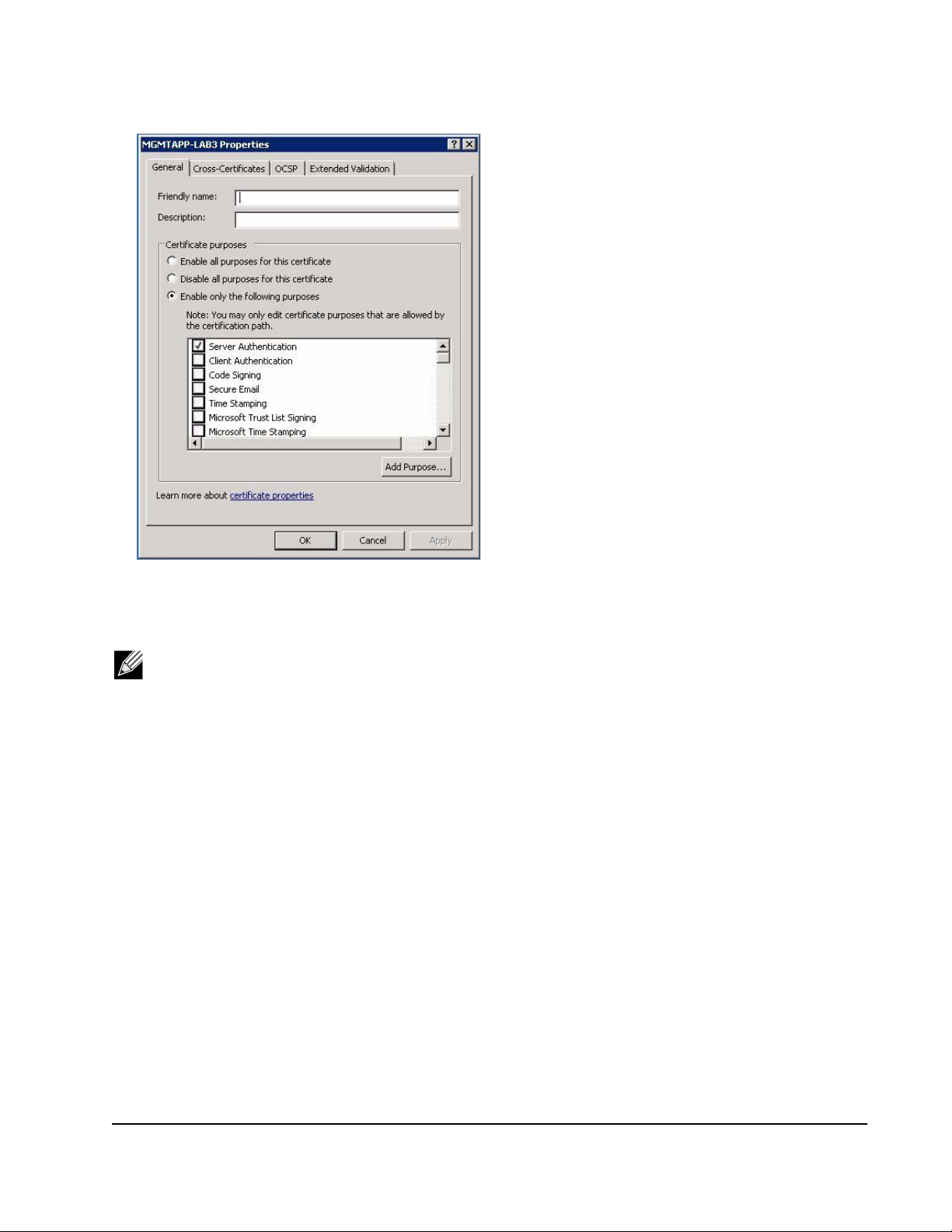
15. Right-click on the certificate and select Properties.
A dialog box displays, as follows:
Document INGSRV170-CDUM100-R Configuring the Communication Protocol To Use With BACS4 Page 26
Page 27
NetXtreme User Guide Windows Driver and Management Application Installation
16. Ensure that only Server Authentication is enabled, as shown in the figure.
17. Open Trusted Root Certification Authorities and then open Certificates.
18. Follow the instructions from Step 11. to Step 17.
Note: See Perform HTTPS Configuration (if you plan to use HTTPS) for instructions on importing the self-signed
certificate on a client.
Step 6: Configure WinRM HTTPS/SSL on the Server
1. Create WinRM Listener, as follows:
a. Click Start (or press the Windows logo key) and select Run.
b. Enter MMC and click OK.
c. Select the self-signed certificate from the Personal store.
For example, if the certificate is created with a host name, the host name will appear.
d. Double-click the certificate to open it.
e. Click the Details tab.
f. Scroll down and select the Thumbprint field.
g. Select and copy the thumbprint in the Details window so you can insert it in the next step.
h. Return to the command prompt.
i. Enter the following command:
winrm create winrm/config/Listener?Address=*+Transport=
HTTPS @{Hostname="<HostName or IPAddress>";
CertificateThumbprint="<paste from the previous step and remove the spaces>"}
Document INGSRV170-CDUM100-R Configuring the Communication Protocol To Use With BACS4 Page 27
Page 28

NetXtreme User Guide Windows Driver and Management Application Installation
Notes:
• If the certificate was generated using the host name, enter the host name. If it was generated using the IP
address, enter the IP address. For an IPv6 address, use brackets [ ] around the address.
• If HTTPS is configured in your system, the listener must be deleted before creating a new HTTPS listener.
Use the following command:
winrm delete winrm/config/Listener?Address=*+Transport=HTTPS
j. The above command creates a listener on the HTTPS port (5986) using any/all network address of the server, and
my SelfSSL generated certificate.
k. You can use the winrm command to modify or set the HTTPS listener, as WinRM listeners can be configured on any
user defined port.
l. From command prompt, run the following command to verify that the listener(s) that have been configured:
winrm e winrm/config/listener
2. Test HTTPS/SSL connection on the server.
a. At the command prompt on the server, enter the following command:
winrs -r:https://yourserver:5986 -u:username -p:password hostname
b. If set up correctly, the output of the command shows the server host name.
c. To check WinRM Service Configuration, run the following command:
winrm get winrm/config/service
Step 7: Additional Server Configuration
If necessary, modify the firewall rules as follows:
Windows Server 2008 R2
1. From the Administrative Tools menu, open Windows Firewall with Advanced Security.
2. Right-click Inbound Rules and select New Rule.
The new rule wizard opens.
3. Select Port and click Next.
4. On the Protocol and Ports screen, select TCP and enter the specific port, for example, 5985 for HTTP or 5986 for
HTTPS.
5. Click Next.
6. On the Action screen, select Allow the connection and click Next.
7. For Profile, you can select all three profiles if your server is in a workgroup.
8. Specify a name for the rule and click Finish.
9. Ensure that the new rule and is enabled (the green check box is selected).
Windows XP
1. Click Start > Control Panel, and then double-click Windows Firewall.
2. Click the Exceptions tab
3. Click Add Port.
4. Enter a meaningful Name, for example “WinRM rule” and port number, for example, 5985 for HTTP or 5986 for HTTPS.
5. Click OK.
Useful WinRM Commands
Document INGSRV170-CDUM100-R Configuring the Communication Protocol To Use With BACS4 Page 28
Page 29

NetXtreme User Guide Windows Driver and Management Application Installation
Command Description
winrm quickconfig or winrm qc Configures WinRM with default settings
winrm enumerate winrm/config/Listener or
winrm e winrm/config/Listener
winrm get winrm/config/Service Checks WinRM Service Configuration.
winrm delete winrm/config/
Listener?Address=*+Transport=HTTPS
Useful WinRM Websites
• http://msdn.microsoft.com/en-us/library/aa384372%28v=vs.85%29.aspx
• http://technet.microsoft.com/en-us/library/cc782312%28WS.10%29.aspx
• http://msdn.microsoft.com/en-us/library/aa384295%28v=VS.85%29.aspx
• The following articles on “http://support.microsoft.com:
• “Configuring WINRM for HTTPS”
• “Windows Management Framework (Windows PowerShell 2.0, WinRM 2.0, and BITS 4.0)”
Helps to check which service listener are enabled and listening on
which port and IP Address.
Deletes a Listener (in this case deleting a HTTPS listener).
WS-MAN Windows Client Installation
On the Windows client, perform following configuration steps.
1. Perform HTTP Configuration (if you plan to use HTTP)
a. Click Start (or press the Windows logo key) and select Run.
b. Enter gpedit.msc to open the local Group Policy editor.
c. Under Computer Configuration, open the Administrative Templates folder and then open the Windows
Components folder.
d. Select Windows Remote Management (WinRM).
e. Under Windows Remote Management (WinRM), select WinRm Client.
f. Under WinRM Client, double-click Trusted Hosts.
g. In the TrustedHostsList, enter the host names of the clients and click OK. If all clients are trusted then enter “*” only.
h. Select WinRM Service.
i. Enable Allow Basic Authentication and click OK.
j. Run the following command from the command prompt to test the connection:
winrm id -remote:<remote machine Hostname or IP Address>
2. Perform HTTPS Configuration (if you plan to use HTTPS)
After you generate a self-signed certificate, as described in To generate a self-signed certificate for the Windows Server:,
you can import the certificate on the client to facilitate a connection between server and client. Ensure that all steps
mentioned in section To generate a self-signed certificate for the Windows Server: are completed, including copying
hostname.pfx at the location from where client can access it, before you proceed with the following steps.
a. Click Start (or press the Windows logo key) and select Run.
b. Enter MMC and click OK.
c. Click File and select Add/Remove Snap-in.
d. Click Add.
e. Select Certificates and click Add.
f. Select Computer account and click Next.
g. Click Finish.
Document INGSRV170-CDUM100-R Configuring the Communication Protocol To Use With BACS4 Page 29
Page 30

NetXtreme User Guide Windows Driver and Management Application Installation
h. Click Close and then click OK.
i. Under Certificates (Local Computer), right-click on Trusted Root Certification Authorities, select All Tasks, and
select Import.
j. Click Next to begin the Certificate Import Wizard.
k. Browse to select the .pfx file you generated in To generate a self-signed certificate for the Windows Server:. Change
the selection in the Files of type list to Personal Information Exchange (*.pfxas, *.p12), select the hostname.pfx
file and click Open.
l. Enter the password you assigned to the private key and click Next.
3. Configure WinRM HTTPS/SSL
You can run winrm from a client to retrieve information from the server using WinRM HTTPS connection. Use the
following steps to test the WinRM HTTPS/SSL connection from client:
a. To retrieve the server operating system information, enter the following command.
winrm e wmi/root/cimv2/Win32_OperatingSystem -r:https://yourservername -u:username
-p:password -skipCAcheck
b. To retrieve the server WinRM identity information, enter the following command.
winrm id -r:https://yourservername -u:username -p:password -skipCAcheck
c. To enumerate Windows services on the server, enter the following command.
winrm e wmicimv2/Win32_service -r:https://yourservername -u:username -p:password skipCAcheck
Note: It is important to use -skipCAcheck switch in the winrm command line testing, as the certificate is self-
generated and not imported on the client. Otherwise, the following error message displays: WSManFault.
Document INGSRV170-CDUM100-R Configuring the Communication Protocol To Use With BACS4 Page 30
Page 31

NetXtreme User Guide Windows Driver and Management Application Installation
USING WMI
No special configuration is required to use WMI on the Windows client. Perform the steps in the following sections to
configure WMI on the Windows server.
Step 1: Set up Namespace Security Using WMI Control
The WMI Control provides one way to manage namespace security. You can start the WMI Control from the command
prompt using this command:
wmimgmt
On Windows 9x or Windows NT4 computers that have WMI installed, use this command instead:
wbemcntl.exe
Alternatively, you can access the WMI Control and the Security tab as follows:
1. Right-click on My Computer and click Manage.
2. Double-click Services and Applications and then double-click WMI Control.
3. Right-click WMI Control and then click Properties.
4. In WMI Control Properties, click the Security tab.
5. A folder named Root with a plus sign (+) next to it should now be visible. Expand this tree as necessary to locate the
namespace for which you want to set permissions.
6. Click Security.
A list of users and their permissions appears. If the user is on the list, modify the permissions as appropriate. If the user
is not on the list, click Add and add the user from the location (local machine, domain, etc.) where the account resides.
Note: You can add these exports at the end of the .bash_profile. This file is located in the /root directory.
• In order to view and set namespace security, the user must have Read Security and Edit Security
permissions. Administrators have these permissions by default, and can assign the permissions to other user
accounts as required.
• If this user needs to access the namespace remotely, you must select the Remote Enable permission.
• By default, user permissions set on a namespace apply only to that namespace. If you want the user to have
access to a namespace and all subnamespaces in the tree below it, or in subnamespaces only, click
Advanced. Click Edit and specify the scope of access in the dialog box that displays.
Step 2: Grant DCOM Remote Launch and Activate Permission
In the Windows domain environment, the Domain Administrator account has the necessary privilege level to access the WMI
component for BACS management and, therefore, no special configuration is needed. In a large enterprise, however, a user
who is accessing the local or remote host using the BACS4 client GUI may not always have the domain administrator
account privilege. It is necessary to configure WMI security access on the remote host to allow the user to connect to it using
the BACS4 client GUI.
This configuration can be easily done using the following procedure. If you do not have sufficient privileges to configure
security for WMI access, contact your Network Administrator.
1. Click Start, click Run, type DCOMCNFG, and then click OK.
2. The Component Services dialogue box displays.
Document INGSRV170-CDUM100-R Configuring the Communication Protocol To Use With BACS4 Page 31
Page 32

NetXtreme User Guide Windows Driver and Management Application Installation
3. Open Component Services and then open Computers.
4. Right-click My Computer and click Properties.
5. In My Computer Properties, click the COM Security tab.
6. Under Launch and Activation Permissions, click Edit Limits.
7. Follow these steps if your name or your group does not appear in the Groups or user names list.
a. In the Launch Permission dialog box, click Add.
b. In the Select Users, Computers, or Groups dialog box, add your name and the group in the Enter the object names
to select box, and then click OK.
c. In the Launch Permission dialog box, select your user and group in the Group or user names list.
d. In the Permissions for User area, select Allow for Remote Launch and Remote Activation, and then click OK.
Figure 1: Launch and Activation Permission
For more information, see Securing a Remote WMI Connection on the Microsoft Developer Network site.
Special Configuration for WMI on Different Systems
In Windows Vista and Windows 7, in order to let all users in the administrator group connect using the WMI namespace, the
user might need to change the LocalAccountTokenFilterPolicy as needed.
Document INGSRV170-CDUM100-R Configuring the Communication Protocol To Use With BACS4 Page 32
Page 33

NetXtreme User Guide Linux Driver and Management Application Installation
Section 4: Linux Driver and
Management Application
Installation
• Packaging
• Installing TG3 Driver Software
• Network Installations
• Unloading/Removing the TG3 Driver
• Driver Messages
• Teaming with Channel Bonding
• Linux Management Application Installation
Packaging
The Linux TG3 driver is released in the following packaging formats (file names):
• Source RPM (tg3-version.src.rpm)
• Supplemental (tg3_sup-version.tar.gz)
• Compressed tar (tg3-version.tar.gz)
Identical source files to build the driver are included in both RPM and TAR source packages. The tar file contains additional
utilities such as patches and driver disk images for network installation.
Document INGSRV170-CDUM100-R Packaging Page 33
Page 34

NetXtreme User Guide Linux Driver and Management Application Installation
Installing TG3 Driver Software
• Installing the Source RPM Package
• Building the Driver from the Source TAR File
Installing the Source RPM Package
Prerequisites:
• Linux kernel source
• C compiler
Procedure:
1. Install the source RPM package.
rpm -ivh tg3-version.src.rpm
2. Change the directory to the RPM path and build the binary driver for your kernel (the RPM path is different for different
Linux distributions).
cd /usr/src/redhat,OpenLinux,turbo,packages,rpm …
rpm -bb SPECS/tg3.spec or rpmbuild -bb SPECS/tg3.spec
rpmbuild -bb SPECS/tg3.spec (for RPM version 4.x.x)
Note: During your attempt to install a source RPM package, the following message may be displayed:
error: cannot create %sourcedir /usr/src/redhat/SOURCE
The most likely cause of the error is that the rpm-build package has not been installed. Locate the rpm-build package on
the Linux installation media and install it using the following command:
rpm -ivh rpm-build-version.i386.rpm
Complete the installation of the source RPM.
3. Install the newly-built package (driver and man page).
rpm -ivh RPMS/i386/tg3-version.i386.rpm
Depending on the kernel, the driver is installed to the following path:
2.6.x kernels:
/lib/modules/kernel_version/kernel/drivers/net/tg3.ko
4. Load the driver.
modprobe tg3
To configure the network protocol and address, refer to the Linux version-specific documentation.
Document INGSRV170-CDUM100-R Installing TG3 Driver Software Page 34
Page 35

NetXtreme User Guide Linux Driver and Management Application Installation
BUILDING THE DRIVER FROM THE SOURCE TAR FILE
1. Create a directory (tg3-version) and extract the TAR files to the directory.
tar xvzf tg3-version.tgz
2. Build the driver tg3.o as a loadable module for the running kernel.
CD tg3-version
make clean
make; make install
3. Test the driver by loading it.
rmmod tg3
modprobe tg3
No message should be returned if this command runs properly.
Note: See the RPM instructions above for the location of the installed driver.
4. To configure network protocol and address, refer to the manuals supplied with your operating system.
Network Installations
For network installations through NFS, FTP, or HTTP (using a network boot disk or PXE), use the tg3 driver that is part of
the Linux operating system distribution.
Unloading/Removing the TG3 Driver
• Unloading/Removing the Driver from an RPM Installation
• Removing the Driver from a TAR Installation
Unloading/Removing the Driver from an RPM Installation
To unload the driver, use ifconfig to bring down all ethX interfaces opened by the driver, and then type the following:
rmmod tg3
If the driver was installed using rpm, do the following to remove it:
rpm -e tg3-<version>
Document INGSRV170-CDUM100-R Network Installations Page 35
Page 36

NetXtreme User Guide Linux Driver and Management Application Installation
Removing the Driver from a TAR Installation
If the driver was installed using make install from the tar file, the tg3.o driver file has to be manually deleted from the operating
system. See Installing the Source RPM Package for the location of the installed driver.
If there is an interface configuration that is related to the tg3 driver, then bring the interface down first by using ifconfig ethx
down and then rmmod tg3.
Driver Messages
The following are the most common sample messages that may be logged in the /var/log/messages file. Use dmesg -nlevel
to control the level at which messages appear on the console. Most systems are set to level 6 by default.
Driver Sign on
tg3.c:version (date)
NIC Detected
eth#: Tigon3 [partno (BCM95xxx) rev 4202 PHY (57xx) (PCI Express) 10/100/1000BaseT
Ethernet :00:xx:xx:xx:xx:xx
eth#: RXcsums [1] LinkChg REG [0] MIirq [0] ASF [0] Split [0] Wirespeed [1]TSOcap [1]
eth#: dma_rwctrl [76180000]
ACPI : PCI interrupt 0000:02:02.0 [A] -> GSI 26 (level,low) -> IRQ 233
Flow Control
tg3: eth#: Flow control is configured for TX and for RX.
Link Up and Speed Indication
tg3: eth#: Link is up at 1000 Mbps, full duplex.
Link Down Indication
tg3: eth#: Link is down.
Teaming with Channel Bonding
With the TG3 driver, you can team adapters together using the bonding kernel module and a channel bonding interface.
Refer to your Linux documentation for more information on Linux Channel Bonding.
Document INGSRV170-CDUM100-R Driver Messages Page 36
Page 37

NetXtreme User Guide Linux Driver and Management Application Installation
Linux Management Application Installation
• Overview
• Installing WS-MAN or CIM-XML on Linux Server
• Installing WS-MAN or CIM-XML on Linux Client
• Installing the Broadcom Advanced Control Suite
Overview
The Broadcom Advanced Control Suite version 4 (BACS4) is a management application for configuring the NetXtreme I
families of adapters. BACS4 GUI software operates on Windows and BACS CLI is used on Linux server operating systems.
This chapter describes how to install the BACS4 management application on Linux systems. For Windows systems,
an installation program is provided which installs both the Windows drivers and the management applications, including
BACS4 (see Windows Driver and Management Application Installation for instructions).
There are two main components of the BACS4 utility: the provider component and the client software. A provider is installed
on a server, or “managed host”, that contains one or more NICs. The provider collects information on the NICs and makes
it available for retrieval from a management PC on which the client software is installed. The client software enables viewing
information from the providers and configuring the NICs.The BACS client software includes a command line interface (CLI).
Communication Protocols
A communication protocol enables exchanging information between provider and the client software. These are proprietary
or open-source implementations of the Web-Based Enterprise Management (WBEM) and Common Information Model (CIM)
standards from the Distributed Management Task Force (DMTF). Network administrators can choose the best option based
on the prevailing standard on their network.
The following table shows the available options based on the operating systems installed on the managed host and the
client.
If the client uses: And the managed host uses: BACS can use these communication protocols:
Windows Windows WMI
WS-MAN (WinRM)
Windows Linux CIM-XML (OpenPegasus)
WS-MAN (OpenPegasus)
Linux Windows WS-MAN (WinRM)
Linux Linux CIM-XML (OpenPegasus)
WS-MAN (OpenPegasus)
• WMI = Windows Management Instrumentation.
• WS-MAN = Web Service-Management. WinRM is a Windows-based implementation and OpenPegasus is an opensource implementation of the that operates on Linux.
• CIM-XML = An XML-based version of OpenPegasus.
Document INGSRV170-CDUM100-R Linux Management Application Installation Page 37
Page 38

NetXtreme User Guide Linux Driver and Management Application Installation
If your network includes a mix of Windows and Linux clients accessing Windows and Linux servers, then WS-MAN is a
suitable choice. If Linux is the only OS installed on the servers, then CIM-XML is an option. If the network includes only
Windows servers and clients, WMI is an option. WMI is very simple to configure but is supported only on the Windows OS.
(See Windows Driver and Management Application Installation for instructions on installing and configuring the Windows
protocols.)
BACS installation includes installing the provider component on the managed host and the client software on the
management station. The installation process differs based on the combination of operating systems installed on the client
and managed host and on the selected communication protocol.
Installing WS-MAN or CIM-XML on Linux Server
Step 1: Install OpenPegasus
On the Red Hat Linux OS, two installation options are available:
• From the Inbox RPM (Red Hat Only)
• From Source (Red Hat and SuSE)
On the SUSE Linux Enterprise Server 11 (SLES11) OS, you must use the source RPM.
Note: The Inbox RPM does not support the WS-MAN communication protocol. To use WS-MAN, you must install
OpenPegasus from source.
From the Inbox RPM (Red Hat Only)
In Red Hat Linux, an Inbox OpenPegasus RPM is available as tog-pegasus-<version>.<arch>.rpm.
1. Use the following command to install tog-pegasus:
rpm -ivh tog-openpegasus-<version>.<arch>.rpm
2. Use the following command to start Pegasus:
/etc/init.d/tog-pegasus start
Note: On SuSE Linux, the Inbox OpenPegasus RPM is not available. OpenPegasus must be installed form
source, as described in the following procedure.
Note that in inbox Pegasus, HTTP is not enabled by default. After Inbox OpenPegasus is installed successfully, if no further
configuration is required, then follow the instructions in Step 4: Install Broadcom CMPI Provider. To enable HTTP, see
Enable HTTP.
From Source (Red Hat and SuSE)
The OpenPegasus source can be downloaded from www.openpegasus.org.
Note: If not already installed, download and install the openssl and libopenssl-devel rpm. This step is optional and
required only if you are planning to use HTTPS to connect the client to the managed host.
Document INGSRV170-CDUM100-R Linux Management Application Installation Page 38
Page 39

NetXtreme User Guide Linux Driver and Management Application Installation
Set the Environment Variables
Set the environment variables for building OpenPegasus as follows.
Environment Variable Description
PEGASUS_ROOT The location of the Pegasus source tree
PEGASUS_HOME The location for the built executable, repository; e.g.,
$PEGASUS_HOME/bin, PEGASUS_HOME/lib,
$PEGAUS_HOME/repository, and $PEGASUS_HOME/mof
subdirectories.
PATH $PATH:$PEGASUS_HOME/bin
PEGASUS_ENABLE_CMPI_PROVIDER_MANAGER True
PEGASUS_CIM_SCHEMA "CIM222"
PEGASUS_PLATFORM For Linux 32 bit systems: "LINUX_IX86_GNU"
For Linux 64 bit systems: "LINUX_X86_64_GNU"
PEGASUS_HAS_SSL Optional. Set to "true" for HTTPS support.
PEGASUS_ENABLE_PROTOCOL_WSMAN Optional. Set to "true" for WSMAN protocol support.
Additional Settings
The $PEGASUS_HOME variable must be set up in the shell environment, and $PEGASUS_HOME/bin needs to be
appended to the $PATH environment.
Examples
• export PEGASUS_PLATFORM="LINUX_X86_64_GNU"
• export PEGASUS_CIM_SCHEMA="CIM222"
• export PEGASUS_ENABLE_CMPI_PROVIDER_MANAGER=true
• export PEGASUS_ROOT="/share/pegasus-2.10-src"
• export PEGASUS_HOME="/pegasus"
• export PATH=$PATH:$PEGASUS_HOME/bin
For SSL Support, add the following environment variable:
• export PEGASUS_HAS_SSL=true
For WS-MAN Support, add the following environment variable:
• export PEGASUS_ENABLE_PROTOCOL_WSMAN=true
CIM-XML and WSMAN in OpenPegasus use the same ports for HTTP or HTTPS. The default port numbers for HTTP and
HTTPS are 5989 and 5989, respectively.
Note: You can add these exports at the end of the .bash_profile. This file is located in the /root directory.
• The environment variables will be set when a user logs in using PuTTY.
• On the Linux system itself, for each terminal where the environment variables are not set, run the following
command:
source /root/.bash_profile
• When you logout and login, the environment variables will be set.
Document INGSRV170-CDUM100-R Linux Management Application Installation Page 39
Page 40

NetXtreme User Guide Linux Driver and Management Application Installation
Build and install OpenPegasus
From $PEGASUS_ROOT (the location of the Pegasus source root directory), run the following:
make clean
make
make repository
Note: Whenever OpenPegasus is built from source, all configurations are reset to the default values. If you are
rebuilding OpenPegasus, you must redo the configuration as mentioned in Step 3: Configure OpenPegasus on
the Server.
Step 2: Start CIM Server on the Server
Use the cimserver command to start CIM server. To stop CIM server, use the command cimserver -s.
To check whether OpenPegasus has been installed properly, enter the following command:
cimcli ei -n root/PG_Interop PG_ProviderModule
Note: For OpenPegasus compiled from source, PEGASUS_HOME must be defined when you start CIM server.
Otherwise, CIM server will not load the repository properly. Consider setting PEGASUS_HOME in the
“.bash_profile” file.
Step 3: Configure OpenPegasus on the Server
Use the cimconfig command to configure OpenPegasus, as shown in the following table:
Command Description
cimconfig -l List all valid property names.
cimconfig -l -c List all valid property names and its value
cimconfig -g <property name> Query a particular property.
cimconfig -s <property name>=<value> -p Set a particular property.
cimconfig --help Find out more about the command.
CIM server must be started before running cimconfig, and must be restarted for configuration changes to take effect.
Enable Authentication
The following OpenPegasus properties have to be set as described in this section. Otherwise, the Broadcom CIM Provider
will not work properly. Ensure the following are set before launching BACS and connecting to the provider.
Start CIM server if it is not already started. Then, set the following:
• cimconfig -s enableAuthentication=true -p
• cimconfig -s enableNamespaceAuthorization=false -p
• cimconfig -s httpAuthType=Basic -p
• cimconfig -s passwordFilePath=cimserver.passwd -p
• cimconfig -s forceProviderProcesses=false -p
Document INGSRV170-CDUM100-R Linux Management Application Installation Page 40
Page 41

NetXtreme User Guide Linux Driver and Management Application Installation
If you want root user to connect remotely:
• cimconfig -s enableRemotePrivilegedUserAccess=true -p
User configuration with privilege: The Linux system users are used for OpenPegasus authentication. The systems users
have to be added to OpenPegasus using cimuser to connect via BACS:
• cimuser -a -u <username> -w <password>
Example: cimuser -a -u root -w linux1
Enable HTTP
1. If CIM server is not started, start it.
2. Use the following command to set up an HTTP port (optional):
cimconfig -s httpPort=5988 -p
This property is not available for Inbox OpenPegasus.
3. Use the following command to enable HTTP connection:
cimconfig -s enableHttpConnection=true -p
4. Use the cimserver -s and cimserver commands, respectively, to stop and restart CIM server for the new configuration
to take effect.
Enable HTTPS
1. If CIM server is not started, start it.
2. Set up HTTPS port with the following command (optional):
cimconfig -s httpsPort=5989 -p
This property is not available for inbox OpenPegasus.
3. Enable HTTPS connection with 'the following command:
cimconfig -s enableHttpsConnection=true -p
4. Use the cimserver -s and cimserver commands, respectively, to stop and restart CIM server for the new configuration
to take effect.
Step 4: Install Broadcom CMPI Provider
Ensure that OpenPegasus is installed properly before installing CMPI Provider.
Install
Enter following command to install Broadcom CMPI Provider.
% rpm -i BRCM_CMPIProvider-{version}.{arch}.rpm
Uninstall
Enter following command to uninstall Broadcom CMPI Provider:
% rpm -e BRCM_CMPIProvider
Document INGSRV170-CDUM100-R Linux Management Application Installation Page 41
Page 42

NetXtreme User Guide Linux Driver and Management Application Installation
Step 5: Perform Linux Firewall Configuration, If Required
Follow these procedures to open the appropriate ports in the firewall:
Red Hat
1. Click System, select Administration, and then select Firewall.
2. Select Other Ports.
3. In the Port and Protocol Dialog box, select User Defined.
4. In the Port/Port Range field, add the port number.
5. In the Protocol field, add the protocol as TCP or UDP, etc.
6. Click Apply for the firewall rules to take effect.
Example:
• For CIM-XML over HTTP, the port number is 5988 and protocol is TCP.
• For CIM-XML over HTTPS, the port number is 5989 and protocol is TCP.
SuSE
1. Click Compute and then click YaST.
2. Select Security & Users on the left pane.
3. On the right pane, double-click Firewall.
4. Select Custom Rules on the left pane.
5. On the right pane click Add.
6. Enter the following values:
• Source Network: 0/0 (means all)
• Protocol: TCP (or the appropriate protocol)
• Destination Port: <Port Number> or <Range of Port Numbers>
• Source Port: Leave blank.
7. Click Next and then click Finish for the firewall rules to take effect.
Example:
For CIM-XML, use the following values:
• Source Network: 0/0 (means all)
• Protocol: TCP
• Destination Port: 5988:5989
• Source Port: Leave blank.
Step 6: Install BACS and Related Management Applications
See Installing the Broadcom Advanced Control Suite.
Document INGSRV170-CDUM100-R Linux Management Application Installation Page 42
Page 43

NetXtreme User Guide Linux Driver and Management Application Installation
INSTALLING WS-MAN OR CIM-XML ON LINUX CLIENT
No special software components are required on the Linux client system to use the HTTP except installing the BACS
management application. However, for WS-MAN installations, you can optionally configure the HTTPS protocol for use with
BACS.
Configure HTTPS on Linux Client
Follow these steps if you want to use HTTPS rather than HTTP (WS-MAN only):
Generate a Self-Signed Certificate for Windows/Linux Server
Openssl on Linux or Windows can be used to generate the self-signed certificate, as follows:
Note: You can download and install openssl from http://gnuwin32.sourceforge.net/packages/openssl.htm.
1. Enter the following command to generate a private key:
openssl genrsa -des3 -out server.key 1024
2. You are prompted to enter a passphrase. Be sure to remember the passphrase.
3. Use the following steps to generate a Certificate Signing Request (CSR).
During the generation of the CSR, you are prompted for several pieces of information. When prompted for the “Common
Name”, enter the Windows Server host name or IP address.
Enter the following command (sample responses are show):
openssl req -new -key server.key -out server.csr
If this command does not work, try the following:
openssl req –new –key server.key –out server.csr –config openssl.cnf
The openssl.cnf file should be placed in the same directory where openssl is placed. Openssl.cnf is located in the folder
C:\Program Files (x86)\GnuWin32\share.
The following information is requested:
• Country Name (2 letter code) []:US
• State or Province Name (full name) []: California
• Locality Name (e.g., city) []: Irvine
• Organization Name (e.g., company) []: Broadcom Corporation
• Organizational Unit Name (e.g., section) []: Engineering
• Common Name (e.g., YOUR name) []: Enter the host name or IP address of the Windows server. For iPv6, enter the
Common Name in the format [xyxy:xxx:….::xxx], including the brackets [ ].
• (Optional) Email Address []:
Enter the following additional attributes to be sent with your certificate request:
• A challenge password []:linux1
• An optional company name []:
4. Remove the passphrase from the key.
Enter the following commands:
cp server.key server.key.org
openssl rsa -in server.key.org -out server.key
Document INGSRV170-CDUM100-R Linux Management Application Installation Page 43
Page 44

NetXtreme User Guide Linux Driver and Management Application Installation
5. Generate a self-signed certificate:
To generate a self-signed certificate which is active for 365 days, enter the following command:
openssl x509 -req -days 365 -in server.csr -signkey server.key -out server.crt
The following output displays:
Signature ok
subject=/C=US/ST=California/L=Irvine/O=Broadcom Corporation/OU=Engineering/CN=MGMTAPP-
LAB3/emailAddress=
Getting Private key
6. Enter the following command to verify the generated self-signed certificate.
openssl verify server.crt
The following output displays:
server.crt:/C=US/ST=California/L=Irvine/O=Broadcom Corporation/OU=Engineering/
CN=MGMTAPP- LAB3/emailAddress=
error 18 at 0 depth lookup:self signed certificate
OK
Ignore the error message “error 18 at 0 depth lookup:self signed certificate”. This error indicates that this is a self-signed
certificate.
7. Convert the certificate from “crt” to “pkcs12” format, as follows:
For a Windows server, the certificate should be in pkcs12 format. Enter the following command:
openssl pkcs12 -export -in server.crt -inkey server.key -out hostname.pfx
You will be prompted for the following:
Enter Export Password:
Verifying - Enter Export Password:
Enter the password and be sure to remember it. The password is required when importing the certificate on the Windows
server and client.
8. Make a copy of the certificate file server.crt and place it on the server where BACS will be installed, so that it can be
imported. If you plan to use a Windows or Linux client to connect to the server running BACS, then the certificate also
needs to be transferred (copied and pasted) to the client system.
In Linux, the certificate should have the extension “.pem”. The extension “.crt” and “.pem” are the same, so there is no
need to use the openssl command to convert from .crt to .pem. You can simply copy the file as-is.
Note: A separate certificate must be generated for an IPv4 address, IPv6 address, and Hostname.
Import Self-Signed Certificate on Linux Client
On Linux distributions, note the following certificate directory:
• For all SuSE versions, the certificate directory is /etc/ssl/certs.
• For Red Hat, the certificate directory can be different for each version. For some versions, it is /etc/ssl/certs or /
etc/pki/tls/certs. For other versions, find out the certificate directory.
Document INGSRV170-CDUM100-R Linux Management Application Installation Page 44
Page 45

NetXtreme User Guide Linux Driver and Management Application Installation
Copy hostname.pem, which you created in Generate a Self-Signed Certificate for Windows/Linux Server, into the certificate
directory of the Linux client. For example, if the certificate directory is /etc/ssl/certs, copy hostname.pem to /etc/ssl/
certs.
1. Change directory to /etc/ssl/certs.
2. Create a hash value by running the following command.
openssl x509 -noout -hash -in hostname.pem
A value such as the following will be returned.
100940db
3. Create a symbolic link to the hash value by running the following command:
ln -s hostname.pem 100940db.0
Test HTTPS/SSL Connection from Linux Client
Use the following command to test whether the certificate is installed correctly on Linux:
# curl -v --capath /etc/ssl/certs https://Hostname or IPAddress:5986/wsman
If this fails, then the certificate is not installed correctly and an error message displays, indicating to take corrective action.
Installing the Broadcom Advanced Control Suite
The Broadcom Advanced Control Suite (BACS) software can be installed on a Linux system using the Linux RPM package.
This installation includes a CLI client.
Before you begin:
• Ensure that the Broadcom network adapter(s) is physically installed and the appropriate device driver for the NIC is
installed on the system to be managed by this utility.
• Ensure that the CIM provider is installed properly on the system that is to be managed by this utility.
• For managing iSCSI on Linux hosts, ensure that the open-iscsi and sg utilities are installed on the Linux host.
To install BACS CLI
1. Download the latest BACS management application RPM package.
2. Install the RPM package using the following command:
% rpm -i BACScli-{version}.{arch}.rpm
To use BACS CLI, refer to the file BACSCLI_Readme.txt provided with the release files.
To remove BACS CLI
To uninstall the RPM package, use the following command:
% rpm -e BACScli
Document INGSRV170-CDUM100-R Linux Management Application Installation Page 45
Page 46

NetXtreme User Guide VMware Driver Software
Section 5: VMware Driver Software
• Packaging
• Drivers
Packaging
The VMware driver is released in the following packaging format.
Table 3: VMware Driver Packaging
Format Drivers
VMware VIB vmware-esx-drivers-net-tg3-version.x86_64.vib
Drivers
Download, Install, and Update Drivers
To download, install, or update the VMware ESX/ESXi driver for NetXtreme I GbE network adapters, see http://
www.vmware.com/support.
Driver Parameters
NetQueue
The optional parameter force_netq can be used to set the number of Rx and Tx net queues. BCM57XX devices that support
NetQueue are the BCM5718, BCM5719, BCM5720, BCM5721, and BCM5722.
By default, the driver tries to use the optimal number of NetQueues. To explicitly force the number of queues, set the number
of NetQueues per port via the following command:
esxcfg-module -s force_netq=x,x,x.... tg3
Allowed values for x are –1 to 15:
• 1–15 will force the number of NetQueues for the given NIC.
• 0 disables NetQueue.
• –1 specifies to use the default driver NetQueue value.
The number of “x” entries can go up to 32, which means the maximum supported NICs = 32.
Document INGSRV170-CDUM100-R Packaging Page 46
Page 47

NetXtreme User Guide VMware Driver Software
Example usage:
esxcfg-module -s force_netq=-1,0,1,2 tg3]
• tg3 NIC 0: Use the default number of NetQueues.
• tg3 NIC 1: Disable the NetQueue feature.
• tg3 NIC 2: Use 1 NetQueue.
• tg3 NIC 3: Use 2 NetQueues.
Note that the NIC # above does not correspond to the vmnic<#>. The NIC number is the system vmnic probe order number.
Optimally, the number of NetQueues matches the number of CPUs on the machine.
Driver Parameters
Several optional parameters can be supplied as a command line argument to the vmkload_mod command. These
parameters can also be set via the esxcfg-module command. See the man page for more information.
Driver Defaults
Table 4: VMware Driver Defaults
Parameter Default Value
Speed Autonegotiation with all speeds advertised
Flow Control Autonegotiation with rx and tx advertised
MTU 1500 (range 46–9000)
Rx Ring Size 200 (range 0–511). Some chips are fixed at 64.
Rx Jumbo Ring Size 100 (range 0–255). Not all chips support the jumbo ring and some chips that support
jumbo frames do not use the jumbo ring.
Tx Ring Size 511 (range (MAX_SKB_FRAGS+1) – 511). MAX_SKB_FRAGS varies on different
kernels and different architectures. On a 2.6 kernel for x86, MAX_SKB_FRAGS is
18.
Coalesce RX Microseconds 20 (range 0–1023)
Coalesce RX Microseconds irq 20 (range 0–255)
Coalesce rx frames 5 (range 0–1023)
Coalesce rx frames irq 5 (range 0–255)
Coalesce TX Microseconds 72 (range 0–1023)
Coalesce tx usecs irq 20 (range 0–255)
Coalesce tx frames 53 (range 0–1023)
Coalesce tx frames irq 5 (range 0–255)
Coalesce stats usecs 1000000 (approx. 1 sec.). Some coalescing parameters are not used or have
different defaults on some chips.
MSI Enabled (if supported by the chip and passed the interrupt test).
WoL Disabled
Document INGSRV170-CDUM100-R Drivers Page 47
Page 48

NetXtreme User Guide VMware Driver Software
Driver Messages
The following are the most common sample messages that may be logged in the file /var/log/messages. Use dmesg -n
<level> to control the level at which messages will appear on the console. Most systems are set to level 6 by default. To
see all messages, set the level higher.
Driver Sign On
tg3.c:v3.118g (Jan 4, 2012)
NIC Detected
vmnic0#: Tigon3 [partno (BCM95xxx) rev 4202 PHY (57xx) (PCI Express) 10/100/1000BaseT
Ethernet :00:xx:xx:xx:xx:xx
vmnic0#: RXcsums [1] LinkChg REG [0] MIirq [0] ASF [0] Split [0] Wirespeed [1]TSOcap [1]
vmnic0#: dma_rwctrl [76180000]
ACPI : PCI interrupt 0000:02:02.0 [A] -> GSI 26 (level,low) -> IRQ 233
Link Up and Speed Indication
tg3: vmnic0: Link is up at 1000 Mbps, full duplex.
tg3: vmnic0: Flow control is on for TX and on for RX.
Link Down Indication
tg3: vmnic0: Link is down.
Document INGSRV170-CDUM100-R Drivers Page 48
Page 49

NetXtreme User Guide Using Broadcom Advanced Control Suite 4
Section 6: Using Broadcom
Advanced Control Suite 4
• Broadcom Advanced Control Suite Overview
• Starting Broadcom Advanced Control Suite
• BACS Interface
• Configuring Preferences in Windows
• Connecting to a Host
• Managing the Host
• Managing the Network Adapter
• Viewing Statistics
• Configuring Teaming
• Configuring With the Command Line Interface Utility
• Managing VLANs
• Troubleshooting BACS
Broadcom Advanced Control Suite Overview
Broadcom Advanced Control Suite (BACS) is an integrated utility that provides useful information about each network
adapter that is installed in your system. BACS also enables you to perform detailed tests, diagnostics, and analyses on each
adapter, as well as to view and modify property values and view traffic statistics for network objects. BACS operates on
Windows and Linux operating systems.
Broadcom Advanced Server Program (BASP), which runs within Broadcom Advanced Control Suite, is used to configure
teams for load balancing, fault tolerance, and virtual local area networks (VLANs). BASP functionality is available only on
systems that use at least one Broadcom network adapter. BASP operates on Windows operating systems only.
Note: Some features of BACS are relevant only to particular adapters. Because a single instance of BACS can
be used to communicate with multiple hosts and adapter types, this document describes all BACS features.
The BACS application includes a graphical user interface and a command line interface (BACSCLI). BACS GUI and BACS
CLI can operate on the following operating system families:
• Windows
• Windows Server
• Linux Server
For information on the latest supported OS versions, refer to the release documentation provided with your software
distribution.
Document INGSRV170-CDUM100-R Broadcom Advanced Control Suite Overview Page 49
Page 50

NetXtreme User Guide Using Broadcom Advanced Control Suite 4
Starting Broadcom Advanced Control Suite
In Control Panel, click Broadcom Control Suite 4, or click the BACS icon in the taskbar located at the bottom of the
Windows or Windows Server desktop.
On Linux systems, you can double-click the BACS4 desktop icon, or access the BACS program from the task bar under
System Tools. (If you are having difficulty launching BACS on a Linux system, see the related topic in Troubleshooting
BACS.)
BACS Interface
The BACS interface is comprised of the following regions:
• Explorer View pane
• Context View selector
• Context View pane
• Menu bar
• Description pane
By default, the Explorer View pane is docked and pinned on the left side of the main window, the Context View pane on the
right, the Context View selector below the menu bar, and the Description pane below the Context View pane. Drag the splitter
between any two panes to vary the size of the panes.
Document INGSRV170-CDUM100-R Starting Broadcom Advanced Control Suite Page 50
Page 51

NetXtreme User Guide Using Broadcom Advanced Control Suite 4
Explorer View Pane
You can dock and pin the Explorer View pane on the left side, right side, top, or bottom of the main window.
The Explorer View pane lists the objects that can be viewed, analyzed, tested, or configured by BACS. When an item is
selected in the Explorer View pane, the tabs showing the information and options that are available for the item appear in
the Context View pane.
The organization of this panel is designed to present the manageable objects in the same hierarchical manner as drivers
and its subcomponents. This simplifies the management of various elements of the converged network interface controller.
The top level of the hierarchy is the Host container, which lists all hosts managed by BACS. Below the hosts are the installed
network adapters, with the manageable elements such as physical port, NDIS, and iSCSI below the adapters.
The icon next to each device in the Explorer View pane shows its status. An icon next to a device name that appears normal
means the device is connected and working.
• X. A red “X” that appears on the device’s icon indicates the device is currently not connected to the network.
• Greyed out. A device icon that appears greyed out indicates the device is currently disabled.
Document INGSRV170-CDUM100-R BACS Interface Page 51
Page 52

NetXtreme User Guide Using Broadcom Advanced Control Suite 4
Context View Selector
The Context View selector appears below the menu bar and includes the filter and tab categories. Although you can expand
and collapse the categories that appear on tabs in the Context View pane, you can alternatively display a category by
selecting the box next to the category name.
Filter View
In a multiple-host environment using several C-NICs, there can be a large number of manageable elements per adapter that
can be difficult and cumbersome to view, configure, and manage all elements. Use the filter to select a particular device
function. Possible filter views include:
•All
•Team view
• NDIS view
• iSCSI view
• iSCSI Target view
Context View Pane
The Context View pane displays all the parameters that you can view for the object selected in the Explorer View pane. The
parameters are grouped by tabs and categories, depending on the parameter type. The available tabs are Information,
Configuration, Diagnostics, and Statistics. Because the BACS interface is context-sensitive, only the parameters that apply
to the selected object can be viewed or configured in the Context View pane.
Menu Bar
The following appear on the menu bar, but because the menu items are context-sensitive, not all items will be available at
all times:
File menu
• Team Save As: Saves the current team configurations to a file.
• Team Restore: Restores any saved team configuration from a file.
Action menu
• Remove Host: Removes the selected host.
• Refresh Host: Refreshes the selected host.
View menu
• Explorer View: Displays/hides the Explorer View pane.
• Tool Bar: Displays/hides the tool bar.
• Status Bar: Displays/hides the status bar.
• Broadcom Logo: Displays/hides the Broadcom Logo on BACS to optimize the maximum viewable space.
Document INGSRV170-CDUM100-R BACS Interface Page 52
Page 53

NetXtreme User Guide Using Broadcom Advanced Control Suite 4
Tools menu
• Options: Used for configuring BACS preferences.
Teams (Windows only)
• Create Teams: Creates new teams with either the Teaming Wizard or in Advanced mode.
• Manage Teams: Manages existing teams with either the Teaming Wizard or in Advanced mode.
Description Pane
The Description pane provides information, configuration instructions, and options for the selected parameter in the Context
View pane.
Configuring Preferences in Windows
To enable or disable the BACS tray icon in Windows
On Windows systems, BACS places an icon in the Windows taskbar when the program is installed. Use the Options window
to turn this icon on or off.
1. From the Tools menu, select Options.
2. Select or clear Enable BACSTray (the option is enabled by default).
3. Click OK.
Setting the teaming mode in Windows
1. From the Tools menu, select Options.
2. Select Expert Mode if you do not need the assistance of the teaming wizard to create teams; otherwise, select Wizard
Mode.
3. Click OK.
Setting the Explorer View refresh time in Windows
1. From the Tools menu, select Options.
2. Select Auto to set the Explorer View refresh time to 5 seconds. Otherwise, select Custom and select a time, in seconds.
3. Click OK.
Document INGSRV170-CDUM100-R Configuring Preferences in Windows Page 53
Page 54

NetXtreme User Guide Using Broadcom Advanced Control Suite 4
Connecting to a Host
You can add one or more Windows or Linux hosts to manage from BACS.
To add a local host
1. From the Action menu, click Add Host.
2. For both Windows and Linux hosts, do not change the default settings. The User name and Password are not required
while connecting to the local host.
3. Select Persist if you want BACS to save the information for this host.
4. Click Ok. BACS can now be used to view information and manage the host.
To add a remote host
1. From the Action menu, click Add Host.
2. Type the remote host’s name or IP address in the Host box.
3. Select the protocol from the Protocol list. The protocol options for Windows are WMI, WSMan, or Try All. The protocol
options for Linux are CimXML, WSMan, or Try All. The Try All option forces the GUI client to try all options.
4. Select the HTTP scheme, or the HTTPS scheme for added security.
5. Type the Port Number value you used to configure the host, if it is different than the default value of 5985.
6. Type the User name and Password.
7. Select Persist if you want BACS to save the information for this host. The host will appear in the Explorer Pane whenever
you reopen BACS, and you will not need to enter the host IP address or host name when connecting to the host. For
security reasons, you must enter the User name and Password every time.
8. Click OK.
Document INGSRV170-CDUM100-R Connecting to a Host Page 54
Page 55

NetXtreme User Guide Using Broadcom Advanced Control Suite 4
Managing the Host
At the host level, you can view host information and configure parameters from the following tabs:
• Information
• Configuration
To view host information
Select the host in the Explorer View pane, and then select the Information tab to view host-level information.
Information Tab: Host Information
Host Name. Displays the name of the host.
OS Version Info. Displays the operating system, including the version.
Platform. Displays the hardware architecture platform (for example, 32-bit or 64-bit)
Document INGSRV170-CDUM100-R Managing the Host Page 55
Page 56

NetXtreme User Guide Using Broadcom Advanced Control Suite 4
To configure the host
Select the host in the Explorer View pane, and then select the Configuration tab to configure host-level parameters.
Document INGSRV170-CDUM100-R Managing the Host Page 56
Page 57

NetXtreme User Guide Using Broadcom Advanced Control Suite 4
Managing the Network Adapter
The installed network adapters appear one level below the host in the hierarchical tree in the Explorer View pane. At the
adapter level, you can view information and configure parameters from the following tabs:
• Information
• Configuration
Viewing Adapter Information
The Vital Signs section of the Information tab has useful information about the network adapters that are installed in your
system, such as the link status of the adapter and general network connectivity.
Select the network adapter in the Explorer View pane, and then select the Information tab to view adapter-level
information.
Notes:
• Information about Broadcom network adapters may be more comprehensive than information about network
adapters made by others.
• Some information may not be available for all Broadcom network adapters.
Document INGSRV170-CDUM100-R Managing the Network Adapter Page 57
Page 58

NetXtreme User Guide Using Broadcom Advanced Control Suite 4
Document INGSRV170-CDUM100-R Managing the Network Adapter Page 58
Page 59

NetXtreme User Guide Using Broadcom Advanced Control Suite 4
VIEWING DRIVER INFORMATION
The Driver Information section of the Information tab displays data about the driver for the selected network adapter.
To view Driver Information for any installed network adapter, click the name of the adapter listed in the Explorer View pane,
then click the Information tab.
Driver Status. The status of the adapter driver.
• Loaded. Normal operating mode. The adapter driver has been loaded by Windows and is functioning.
• Not Loaded. The driver associated with the adapter has not been loaded by Windows.
• Information Not Available. The value is not obtainable from the driver that is associated with the adapter.
Driver Name. The file name of the adapter driver.
Driver Version. The current version of the adapter driver.
Driver Date. The creation date of the adapter driver.
Document INGSRV170-CDUM100-R Managing the Network Adapter Page 59
Page 60

NetXtreme User Guide Using Broadcom Advanced Control Suite 4
VIEWING RESOURCE INFORMATION
The Resources section of the Information tab displays information about connections and other essential functions for the
selected network adapter.
To view Resources for any installed network adapter, click the name of the adapter listed in the Explorer View pane, then
click the Information tab.
Note: Some information may not be available for all Broadcom network adapters.
Bus Type. The type of input/output (I/O) interconnect used by the adapter.
Slot No. The slot number on the system board occupied by the adapter. This item is not available for PCI Express type
adapters.
Bus Speed (MHz). The bus clock signal frequency used by the adapter. This item is not available for PCI Express type
adapters.
Bus Width (bit). The number of bits that the bus can transfer at a single time to and from the adapter. This item is not
available for PCI Express type adapters.
Bus No. Indicates the number of the bus where the adapter is installed.
Document INGSRV170-CDUM100-R Managing the Network Adapter Page 60
Page 61

NetXtreme User Guide Using Broadcom Advanced Control Suite 4
Device No. The number assigned to the adapter by the operating system.
Function No. The port number of the adapter. For a single-port adapter, the function number is 0. For a two-port adapter,
the function number for the first port is 0, and the function number for the second port is 1.
Interrupt Request. The interrupt line number that is associated with the adapter. Valid numbers range from 2 to 25.
Memory Address. The memory mapped address that is assigned to the adapter. This value can never be 0.
Viewing Hardware Information
The Hardware section of the Information tab displays information about the hardware settings for the selected network
adapter.
To view Hardware for any installed network adapter, click the name of the adapter listed in the Explorer View pane, then
click the Information tab.
Note: Some information may not be available for all Broadcom network adapters.
Document INGSRV170-CDUM100-R Managing the Network Adapter Page 61
Page 62

NetXtreme User Guide Using Broadcom Advanced Control Suite 4
ASIC Version. The chip version of the Broadcom adapter (this information is not available for adapters made by others).
Firmware Version. The firmware version of the Broadcom adapter (this information is not available for adapters made by
others). This information is only available for Broadcom NetXtreme adapters.
Vendor ID. The vendor ID.
Device ID. The adapter ID.
Subsystem Vendor ID. The subsystem vendor ID.
Subsystem ID. The subsystem ID.
Testing the Network
The Network Test option on the Diagnostics tab lets you verify IP network connectivity. This test verifies if the driver is
installed correctly and tests connectivity to a gateway or other specified IP address on the same subnet. The network test
uses TCP/IP to send ICMP packets to remote systems, then waits for a response.
Note: The network test option is not available on adapters that are grouped into a team (see Configuring
Teaming).
To run the network test
1. Click the name of the adapter to test in the Explorer View pane.
2. From the Select a test to run list, select Network Test. If the Network Test option is not available, then from the
Context View tab on the right side of the window, select Diagnostics and then select Network Test.
3. To change the destination IP address, select IP address to ping. In the Network Test window, enter a Destination IP
address, then click OK.
4. Click Test.
The results of the network test are displayed in the Status field.
Document INGSRV170-CDUM100-R Managing the Network Adapter Page 62
Page 63

NetXtreme User Guide Using Broadcom Advanced Control Suite 4
RUNNING DIAGNOSTIC TESTS
The Diagnostic Tests option on the Diagnostics tab lets you check the state of the physical components on a Broadcom
network adapter. You can trigger the tests manually, or choose to have BACS 3 continuously perform them. If the test are
performed continuously, then the number of passes and fails in the Result field for each test increments every time the tests
are performed. For example, if a test is performed four times and there are no fails, the value in the Result field for that test
is 4/0. However, if there were 3 passes and 1 fail, the value in the Result field is 3/1.
Notes:
• You must have administrator privileges to run diagnostic tests.
• The network connection is temporarily lost while these tests are running.
• Not all Broadcom adapters support each test.
To run the diagnostic tests once
1. Click the name of the adapter to test in the Explorer View pane and select the Diagnostics tab.
2. From the Select a test to run list, select Diagnostic Tests.
3. Select the diagnostic tests you want to run. Click Select All to select all tests or Clear All to clear all test selections.
4. Select the number of times to run the tests from Number of loops.
5. Click Run test(s).
6. In the error message window that warns of the network connection being temporarily interrupted, click Yes. The results
are displayed in the Result field for each test.
Control Registers. This test verifies the read and write capabilities of the network adapter registers by writing various values
to the registers and verifying the results. The adapter driver uses these registers to perform network functions such as
sending and receiving information. A test failure indicates that the adapter may not be working properly.
MII Registers. This test verifies the read and write capabilities of the registers of the physical layer (PHY). The physical layer
is used to control the electrical signals on the wire and to configure network speeds such as 1000 Mbit/s.
EEPROM. This test verifies the content of the electrically erasable programmable read-only memory (EEPROM) by reading
a portion of the EEPROM and computing the checksum. The test fails if the computed checksum is different from the
checksum stored in the EEPROM. An EEPROM image upgrade does not require a code change for this test.
Internal Memory. This test verifies that the internal memory of the adapter is functioning properly. The test writes patterned
values to the memory and reads back the results. The test fails if an erroneous value is read back. The adapter cannot
function if its internal memory is not functioning properly.
On-Chip CPU. This test verifies the operation of the internal CPUs in the adapter.
Interrupt. This test verifies that the Network Device Driver Interface Specification (NDIS) driver is able to receive interrupts
from the adapter.
LoopBack MAC. This test verifies that the NDIS driver is able to send packets to and receive packets from the adapter.
LoopBack PHY. This test verifies that the NDIS driver is able to send packets to and receive packets from the adapter.
Test LED. This test causes all of the port LEDs to blink 5 times for the purpose of identifying the adapter.
Document INGSRV170-CDUM100-R Managing the Network Adapter Page 63
Page 64

NetXtreme User Guide Using Broadcom Advanced Control Suite 4
Analyzing Cables
The Cable Analysis option on the Diagnostics tab lets you monitor the conditions of each wire pair in an Ethernet Category
5 cable connection within an Ethernet network. The analysis measures the cable quality and compares it against the IEEE
802.3ab specification for compliance.
Notes:
• You must have administrator privileges to run the cable analysis test.
• The network connection is temporarily lost during an analysis.
• For Broadcom NetXtreme adapters, the cable analysis test can only run for gigabit link speed connections
and when there is no connection.
• This option is not available for all Broadcom network adapters.
To run a cable analysis
1. Connect the cable to a port on a switch where the port is set to Auto and the Speed & Duplex driver settings are also
set to Auto.
2. Click the name of the adapter to test in the Explorer View pane.
3. From the Select a test to run list, select Cable Analysis. If the Cable Analysis option is not available, then from the
Context View tab on the right side of the window, select Diagnostics and then select Cable Analysis.
4. Click Run.
5. In the error message window that warns of the network connection being temporarily interrupted, click Yes.
Distance. The valid cable distance in meters (except when the Noise result is returned).
Status. This shows the type of link on this cable pair.
• Good. Good cable/PCB signal paths, but no gigabit link.
• Crossed. Pin short or crosstalk along two or more cable/PCB signal paths.
• Open. One or both pins are open for a twisted pair.
• Short. Two pins from the same twisted pair are shorted together.
• Noise. Persistent noise present (most likely caused by Forced 10/100).
• GB Link. Gigabit link is up and running.
• N/A. Algorithm failed to reach a conclusion.
Link. The link connection speed and duplex mode.
Status. The status after the test is run, either completed or failed.
There are several factors that could have an effect on the test results:
• Link partner. Various switch and hub manufacturers implement different PHYs. Some PHYs are not IEEE compliant.
• Cable quality. Category 3, 4, 5, and 6 may affect the test results.
• Electrical interference. The testing environment may affect the test results.
Document INGSRV170-CDUM100-R Managing the Network Adapter Page 64
Page 65

NetXtreme User Guide Using Broadcom Advanced Control Suite 4
Setting Adapter Properties
Advanced on the Configurations tab allow you to view and change the values of the available properties of the selected
adapter. The potentially available properties and their respective settings are described below.
Notes:
• You must have administrator privileges to change the values for a property.
• The list of available properties for your particular adapter may be different.
• Some properties may not be available for all Broadcom network adapters.
To set adapter properties
1. Click the name of the adapter in the Explorer View pane, and click the Configurations tab.
2. From the Advanced section, select the property you want to set.
3. To change the value of a property, select an item from the property’s list or type a new value, as appropriate (selection
options are different for different properties).
4. Click Apply to confirm the changes to all properties. Click Reset to return the properties to their original values.
802.1p QOS. Enables quality of service, which is an Institute of Electrical and Electronics Engineering (IEEE) specification
that treats different types of network traffic diversely to ensure required levels or reliability and latency according to the type
of traffic. This property is disabled by default. Unless the network infrastructure supports QoS, do not enable this property.
Otherwise, problems may occur.
Flow Control. Enables or disables the receipt or transmission of PAUSE frames. PAUSE frames allow the network adapter
and a switch to control the transmit rate. The side that is receiving the PAUSE frame momentarily stops transmitting.
• Auto (default). PAUSE frame receipt and transmission are optimized.
• Disable. PAUSE frame receipt and transmission are disabled.
• Rx PAUSE. PAUSE frame receipt is enabled.
• Rx/Tx PAUSE. PAUSE frame receipt and transmission are enabled.
• Tx PAUSE. PAUSE frame transmission is enabled.
Speed & Duplex. The Speed & Duplex property sets the connection speed and mode to that of the network. Note that FullDuplex mode allows the adapter to transmit and receive network data simultaneously.
• 10 Mb Full. Sets the speed at 10 Mbit/s and the mode to Full-Duplex.
• 10 Mb Half. Sets the speed at 10 Mbit/s and the mode to Half-Duplex.
• 100 Mb Full. Sets the speed at 100 Mbit/s and the mode to Full-Duplex.
• 100 Mb Half. Sets the speed at 100 Mbit/s and the mode to Half-Duplex.
• Auto (default). Sets the speed and mode for optimum network connection (recommended).
Document INGSRV170-CDUM100-R Managing the Network Adapter Page 65
Page 66

NetXtreme User Guide Using Broadcom Advanced Control Suite 4
Notes:
• Auto is the recommended setting. This setting allows the network adapter to dynamically detect the line
speed of the network. Whenever the network capability changes, the network adapter automatically detects
and adjusts to the new line speed and duplex mode. A speed of 1 Gbit/s is enabled by selecting Auto, when
that speed is supported.
• 1 Gb Full Auto must be attached to a link partner that is also capable of a 1 Gb connection. Since the
connection is limited to a 1 Gb connection only, the Ethernet@Wirespeed feature will be disabled. If the link
partner supports a 1 Gb connection only, the Wake on LAN feature may not work. Additionally, management
traffic in the absence of an operating system may also be affected.
• 10 Mb Half and 100 Mb Half settings force the network adapter to connect to the network in Half-Duplex
mode. Note that the network adapter may not function if the network is not configured to operate at the same
mode.
• 10 Mb Full and 100 Mb Full settings force the network adapter to connect to the network in Full-Duplex mode.
The network adapter may not function if the network is not configured to operate at the same mode.
Wake Up Capabilities. Enables the network adapter to wake up from a low-power mode when it receives a network wakeup frame. Two types of wake-up frames are possible: Magic Packet and Wake Up Frame.
This property is only available for Broadcom NetXtreme adapters.
• Both (default). Selects both Magic Packet and Wake Up Frame as wake-up frames.
• Magic Packet. Selects Magic Packet as the wake-up frame.
• None. Selects no wake-up frame.
• Wake Up Frame. Selects Wake Up Frame as the wake-up frame and allows the network adapter to wake the system
when an event such as a ping or an Address Resolution Protocol (ARP) request is received. This option works in
conjunction with the operating system power mode saving and does not work if the Power Save setting does not enable
WOL.
Priority & VLAN. Allows enabling both the prioritization of network traffic and VLAN tagging. VLAN tagging only occurs
when the VLAN ID setting is configured with a value other than 0 (zero).
• Priority & VLAN Enabled (default). Allows for packet prioritization and VLAN tagging.
• Priority & VLAN Disabled. Prevents packet prioritization and VLAN tagging.
• Priority Enabled. Allows packet prioritization only.
• VLAN Enabled. Allows VLAN tagging only.
Note: If an intermediate driver is managing the network adapter for VLAN tagging, the Priority & VLAN Disabled
and Priority Enabled settings should not be used. Use the Priority & VLAN Enabled setting and change the
VLAN ID to 0 (zero).
VLAN ID. Enables VLAN tagging and configures the VLAN ID when Priority & VLAN Enabled is selected as the Priority
& VLAN setting. The range for the VLAN ID is 1 to 4094 and must match the VLAN tag value on the connected switch. A
value of 0 (default) in this field disables VLAN tagging.
Risk Assessment of VLAN Tagging through the NDIS Miniport Driver
Broadcom's NDIS 6.0 miniport driver provides the means to allow a system containing a Broadcom adapter to connect
to a tagged VLAN. Unlike BASP, however, the NDIS 6 driver's support for VLAN participation is only for a single VLAN ID.
Also unlike BASP, the NDIS 6.0 driver only provides VLAN tagging of the outbound packet, but does not provide filtering
of incoming packets based on VLAN ID membership. This is the default behavior of all miniport drivers. While the lack
of filtering packets based on VLAN membership may present a security issue, the following provides a risk assessment
based on this driver limitation for an IPv4 network:
Document INGSRV170-CDUM100-R Managing the Network Adapter Page 66
Page 67

NetXtreme User Guide Using Broadcom Advanced Control Suite 4
A properly configured network that has multiple VLANs should maintain separate IP segments for each VLAN. This
is necessary since outbound traffic relies on the routing table to identify which adapter (virtual or physical) to pass
traffic through and does not determine which adapter based on VLAN membership.
Since support for VLAN tagging on Broadcom's NDIS 6.0 driver is limited to transmit (Tx) traffic only, there is a risk
of inbound traffic (Rx) from a different VLAN being passed up to the operating system. However, based on the
premise of a properly configured network above, the IP segmentation and/or the switch VLAN configuration may
provide additional filtration to limit the risk.
In a back-to-back connection scenario, two computers on the same IP segment may be able to communicate
regardless of their VLAN configuration since no filtration of VLAN membership is occurring. However, this scenario
assumes that the security may already be breached since this connection type is not typical in a VLAN environment.
If the risk above is not desirable and filtering of VLAN ID membership is required, then support through an intermediate
driver would be necessary.
Viewing Statistics
The information provided on the Statistics tab allows you to view traffic statistics for both Broadcom network adapters and
network adapters made by others. Statistical information and coverage are more comprehensive for Broadcom adapters.
To view Statistics information for any installed network adapter, click the name of the adapter listed in the Explorer View
pane, then click the Statistics tab.
Click Refresh to get the most recent values for each statistic. Click Reset to change all values to zero.
Notes:
• Team statistics are not compiled for a Broadcom network adapter if it is disabled.
• Some statistics may not be available for all Broadcom network adapters.
General Statistics
General Statistics show the transmitted and received statistics to and from the adapter.
Frames Tx OK. A count of the frames that were successfully transmitted. This counter is incremented when the transmit
status is reported as Transmit OK.
Frames Rx OK. A count of the frames that were successfully received. This does not include frames received with frametoo-long, frame check sequence (FCS), length, or alignment errors, nor frames lost due to internal MAC sublayer errors. This
counter is incremented when the receive status is reported as Receive OK.
Directed Frames Tx. A count of directed data frames that were successfully transmitted.
Multicast Frames Tx. A count of frames that were successfully transmitted (as indicated by the status value Transmit OK)
to a group destination address other than a broadcast address.
Broadcast Frames Tx. A count of frames that were successfully transmitted (as indicated by the transmit status Transmit
OK) to the broadcast address. Frames transmitted to multicast addresses are not broadcast frames and are excluded.
Document INGSRV170-CDUM100-R Viewing Statistics Page 67
Page 68

NetXtreme User Guide Using Broadcom Advanced Control Suite 4
Directed Frames Rx. A count of directed data frames that were successfully received.
Multicast Frames Rx. A count of frames that were successfully received and are directed to an active nonbroadcast group
address. This does not include frames received with frame-too-long, FCS, length, or alignment errors, nor frames lost
because of internal MAC sublayer errors. This counter is incremented as indicated by the Receive OK status.
Broadcast Frames Rx. A count of frames that were successfully received and are directed to a broadcast group address.
This count does not include frames received with frame-too-long, FCS, length, or alignment errors, nor frames lost because
of internal MAC sublayer errors. This counter is incremented as indicated by the Receive OK status.
Frames Rx with CRC Error. The number of frames received with CRC errors.
Configuring Teaming
The teaming function allows you to group any available network adapters together to function as a team. Teaming is a
method of creating a virtual NIC (a group of multiple adapters that functions as a single adapter). The benefit of this approach
is that it enables load balancing and failover. Teaming is done through the Broadcom Advanced Server Program (BASP)
software. For a comprehensive description of the technology and implementation considerations of the teaming software,
refer to the "Broadcom Gigabit Ethernet Teaming Services" section of your Broadcom network adapter user guide.
Teaming can be accomplished by either of the following methods:
• Using the Broadcom Teaming Wizard
• Using Expert Mode
Notes:
• For further information regarding teaming protocols, see “Teaming” in your Broadcom network adapter user
guide.
• If you do not enable LiveLink™ when configuring teams, disabling Spanning Tree Protocol (STP) at the
switch is recommended. This minimizes the downtime due to spanning tree loop determination when failing
over. LiveLink mitigates such issues.
• BASP is available only if a system has one or more Broadcom network adapters installed.
• The Large Send Offload (LSO) and Checksum Offload properties are enabled for a team only when all of the
members support and are configured for the feature.
• You must have administrator privileges to create or modify a team.
• The load balance algorithm in a team environment in which members are connected at different speeds
favors members connected with a Gigabit Ethernet link over members connected at lower speed links (100
Mbps or 10 Mbps) until a threshold is met. This is normal behavior.
• Wake on LAN (WOL) is a feature that allows a system to be awakened from a sleep state by the arrival of a
specific packet over the Ethernet interface. Because a virtual adapter is implemented as a software only
device, it lacks the hardware features to implement WOL and cannot be enabled to wake the system from a
sleeping state via the virtual adapter. The physical adapters, however, support this property, even when the
adapter is part of a team.
Document INGSRV170-CDUM100-R Configuring Teaming Page 68
Page 69

NetXtreme User Guide Using Broadcom Advanced Control Suite 4
Team Types
You can create four types of load balance teams:
• Smart Load Balance and Failover
• Link Aggregation (802.3ad)
• Generic Trunking (FEC/GEC)/802.3ad-Draft Static
• SLB (Auto-Fallback Disable) – The Auto-Fallback Disable feature is configured for Smart Load Balance and Failover
type teams in the Teaming Wizard.
For a description of these types, see “Load Balancing and Fault Tolerance” in the Broadcom® NetXtreme® BCM57XX User
Guide.
Using the Broadcom Teaming Wizard
You can use the Broadcom Teaming Wizard to create a team, configure an existing team if a team has already been created,
or create a VLAN.
1. Create or edit a team:
To create a new team, select Create a Team from the Team menu, or right-click one of the devices in the “Unassigned
Adapters” section and select Create a Team. This option is not available if there are no devices listed in the “Unassigned
Adapters” sections, which means all adapters are already assigned to teams.
To configure an existing team, right-click one of the teams in the list and select Edit Team. This option is only available
if a team has already been created and is listed in the Team Management pane.
Note: If you prefer to work without the wizard for now, click Expert Mode. If you want to always use Expert Mode
to create a team, select Default to Expert Mode on next start. See Using Expert Mode.
2. To continue using the wizard, click Next.
Document INGSRV170-CDUM100-R Configuring Teaming Page 69
Page 70

NetXtreme User Guide Using Broadcom Advanced Control Suite 4
3. Type the team name and then click Next. If you want to review or change any of your settings, click Back. Click Cancel
to discard your settings and exit the wizard.
Note: The team name cannot exceed 39 characters, cannot begin with spaces, and cannot contain any of the
following characters: & \ / : * ? < > |
Document INGSRV170-CDUM100-R Configuring Teaming Page 70
Page 71

NetXtreme User Guide Using Broadcom Advanced Control Suite 4
4. Select the type of team you want to create. If the team type is an SLB type team, click Next. If the team type is not an
SLB type team, then a dialog box appears. Verify that the network switch connected to the team members is configured
correctly for the team type, click OK, and continue.
Document INGSRV170-CDUM100-R Configuring Teaming Page 71
Page 72

NetXtreme User Guide Using Broadcom Advanced Control Suite 4
5. From the Available Adapters list, click the adapter you want to add to the team and then click Add. Remove team
members from the Team Members list by clicking the adapter and then clicking Remove. Click Next.
Note: There must be at least one Broadcom network adapter assigned to the team.
The Large Send Offload (LSO) and Checksum Offload (CO) columns indicate if the LSO, and/or the CO properties are
supported for the adapter. The LSO, and CO properties are enabled for a team only when all of the members support
and are configured for the feature. If this is the case, then the team offload capabilities appear on the bottom of the
screen.
Note: Adding a network adapter to a team where its driver is disabled may negatively affect the offloading
capabilities of the team. This may have an impact on the team’s performance. Therefore, it is recommended that
only driver-enabled network adapters be added as members to a team.
Document INGSRV170-CDUM100-R Configuring Teaming Page 72
Page 73

NetXtreme User Guide Using Broadcom Advanced Control Suite 4
6. If you want to designate one of the adapters as a standby member (optional), select Use the following member as a
standby member, then choose the standby member from the list of adapters.
7. The Auto-Fallback Disable mode feature allows the team to continue using the standby member rather than switching
back to the primary member if the primary member comes back online. To enable this feature, select Enable AutoFallback Disable mode. Click Next.
Document INGSRV170-CDUM100-R Configuring Teaming Page 73
Page 74

NetXtreme User Guide Using Broadcom Advanced Control Suite 4
8. If you want to configure LiveLink, select Yes, otherwise select No, then click Next.
Document INGSRV170-CDUM100-R Configuring Teaming Page 74
Page 75

NetXtreme User Guide Using Broadcom Advanced Control Suite 4
9. Select the probe interval (the number of seconds between each retransmission of a link packet to the probe target) and
the maximum number of probe retries (the number of consecutively missed responses from a probe target before a
failover is triggered).
10. Set the Probe VLAN ID to allow for connectivity with probe targets residing on a tagged VLAN. The number set must
match the VLAN ID of the probe targets as well as the port(s) on the switch to which the team is connected.
Note: Each LiveLink enabled team can only communicate with Probe Targets on a single VLAN. Also, VLAN ID 0
is equivalent to an untagged network. If the Probe VLAN ID is set to a value other than 0, then a VLAN must be
created with an identical VLAN tag value (see Step 16.).
11. Click the probe target at the top of the list, click Edit Target IP Address, type the target IP address in the IP Address
box for one or all probe targets, and then click OK. Click Next.
Note: Only the first probe target is required. You can specify up to three additional probe targets to serve as
backups by assigning IP addresses to the other probe targets.
12. Select a listed team member, click Edit Member IP Address, and then type the member IP address in the IP Address
box. Repeat for all listed team members and then click OK. Click Next.
Note: All of the member IP addresses must be in the same subnet as the subnet of the probe targets.
13. If you want to create a VLAN on the team, select Add VLAN, or if you want to change the settings of an existing VLAN,
select Edit VLAN, then click Next. If you do not want to create or edit a VLAN, select Skip Manage VLAN, then click
Next, and continue with the wizard from the Finish screen (see Step 18. of this procedure).
VLANs enable you to add multiple virtual adapters that are on different subnets. The benefit of this is that your system
can have one network adapter that can belong to multiple subnets.
Document INGSRV170-CDUM100-R Configuring Teaming Page 75
Page 76

NetXtreme User Guide Using Broadcom Advanced Control Suite 4
Note: VLANs can only be created when all team members are Broadcom adapters.
14. Type the VLAN name and then click Next.
Note: The team name cannot exceed 39 characters, cannot begin with spaces, and cannot contain any of the
following characters: & \ / : * ? < > |
Document INGSRV170-CDUM100-R Configuring Teaming Page 76
Page 77

NetXtreme User Guide Using Broadcom Advanced Control Suite 4
15. To tag the VLAN, select Tagged and then click Next. Otherwise, click Untagged, click Next, and continue with the
wizard to add additional VLANs (see Step 17. of this procedure).
Document INGSRV170-CDUM100-R Configuring Teaming Page 77
Page 78

NetXtreme User Guide Using Broadcom Advanced Control Suite 4
16. Type the VLAN tag value and then click Next. The value must be between 1 and 4094.
Document INGSRV170-CDUM100-R Configuring Teaming Page 78
Page 79

NetXtreme User Guide Using Broadcom Advanced Control Suite 4
17. Select Yes to add or manage another VLAN and then click Next. Repeat until you do not want to add or manage any
additional VLANs.
Note: You can define up to 64 VLANs per team (63 VLANs that are tagged and 1 VLAN that is not tagged). Adding
several VLANS may slow down the reaction time of the Windows interface due to memory and processor time
usage for each VLAN. The degree to which Windows performance may suffer depends on system configuration.
18. To apply and commit the changes to the team, select Commit changes to system and Exit the wizard. To apply your
changes but continue using the wizard, select Save changes and continue to manage more teams. Click Finish.
Document INGSRV170-CDUM100-R Configuring Teaming Page 79
Page 80

NetXtreme User Guide Using Broadcom Advanced Control Suite 4
Note: At any point in the Broadcom Teaming Wizard procedure, click Preview to get a visual representation of
what the team will look like before committing any changes.
Document INGSRV170-CDUM100-R Configuring Teaming Page 80
Page 81

NetXtreme User Guide Using Broadcom Advanced Control Suite 4
19. Click the team name in the Team Management pane to view the team's properties in the Information tab, transfer and
receive data in the Statistics tab.
Document INGSRV170-CDUM100-R Configuring Teaming Page 81
Page 82

NetXtreme User Guide Using Broadcom Advanced Control Suite 4
Using Expert Mode
Use Expert Mode to create a team, modify a team, add a VLAN, and configure LiveLink for a Smart Load Balance and
Failover and SLB (Auto-Fallback Disable) team. To create a team using the wizard, see Using the Broadcom Teaming
Wizard.
To set the default Teaming Mode, select Options from the Tools menu, then select Expert Mode or Wizard Mode (the
default is Wizard Mode).
Creating a Team
Note: Enabling Dynamic Host Configuration Protocol (DHCP) is not recommended for members of an SLB type
of team.
1. From the Teams menu, select Create Team, or right-click one of the devices in the “Unassigned Adapters” section and
select Create a Team. This option is not available if there are no devices listed in the “Unassigned Adapters” sections,
which means all adapters are already assigned to teams.
2. Click Expert Mode.
Note: If you want to always use Expert Mode to create a team, click Default to Expert Mode on next start.
Document INGSRV170-CDUM100-R Configuring Teaming Page 82
Page 83

NetXtreme User Guide Using Broadcom Advanced Control Suite 4
3. Click the Create Team tab.
Note: The Create Team tab appears only if there are teamable adapters available.
4. Click the Team Name field to enter a team name.
5. Click the Team Type field to select a team type.
6. Assign any available adapter or adapters to the team by selecting the adapter from the Load Balance Members list.
There must be at least one adapter selected in the Load Balance Members list.
7. You can assign any other available adapter to be a standby member by selecting it from the Standby Member list.
Note: There must be at least one Broadcom network adapter assigned to the team.
The Large Send Offload (LSO), Checksum Offload (CO), and RSS indicate if the LSO, CO, and/or RSS properties are
supported for the team. The LSO, CO, and RSS properties are enabled for a team only when all of the members support
and are configured for the feature.
Note: Adding a network adapter to a team where its driver is disabled may negatively affect the offloading
capabilities of the team. This may have an impact on the team’s performance. Therefore, it is recommended that
only driver-enabled network adapters be added as members to a team.
Document INGSRV170-CDUM100-R Configuring Teaming Page 83
Page 84

NetXtreme User Guide Using Broadcom Advanced Control Suite 4
8. Type the value for Team MTU.
9. Click Create to save the team information.
10. Repeat steps 4. through 9. to define additional teams. As teams are defined, they can be selected from the team list, but
they have not yet been created. Click the Preview tab to view the team structure before applying the changes.
11. Click Apply/Exit to create all the teams you have defined and exit the Manage Teams window.
12. Click Yes when the message is displayed indicating that the network connection will be temporarily interrupted.
Notes:
• The team name cannot exceed 39 characters, cannot begin with spaces, and cannot contain any of the
following characters: & \ / : * ? < > |
• Team names must be unique. If you attempt to use a team name more than once, an error message is
displayed indicating that the name already exists.
• The maximum number of team members is 8.
• When team configuration has been correctly performed, a virtual team adapter driver is created for each
configured team.
• If you disable a virtual team and later want to reenable it, you must first disable and reenable all team
members before you reenable the virtual team.
• When you create Generic Trunking and Link Aggregation teams, you cannot designate a standby member.
Standby members work only with Smart Load Balancing and Failover and SLB (Auto-Fallback Disable) types
of teams.
• For an SLB (Auto-Fallback Disable) team, to restore traffic to the load balance members from the standby
member, click the Fallback button on the Team Properties tab.
• When configuring an SLB team, although connecting team members to a hub is supported for testing, it is
recommended to connect team members to a switch.
• Not all network adapters made by others are supported or fully certified for teaming.
13. Configure the team IP address.
a. From Control Panel, double-click Network Connections.
b. Right-click the name of the team to be configured, and then click Properties.
c. On the General tab, click Internet Protocol (TCP/IP), and then click Properties.
d. Configure the IP address and any other necessary TCP/IP configuration for the team, and then click OK when
finished.
Document INGSRV170-CDUM100-R Configuring Teaming Page 84
Page 85

NetXtreme User Guide Using Broadcom Advanced Control Suite 4
MODIFYING A TEAM
After you have created a team, you can modify the team in the following ways:
• Change the type of team
• Change the members assigned to the team
• Add a VLAN
• Modify a VLAN (using Expert Mode)
• Remove a team or a VLAN (using Expert Mode)
To modify a team
1. From the Team menu, click Edit Team, or right-click one of the teams in the list and select Edit Team. This option is
only available if a team has already been created and is listed in the Team Management pane.
2. The wizard Welcome screen appears. Click Next to continue modifying a team using the wizard or click Expert Mode to
work in Expert Mode.
Note: The Edit Team tab in Expert Mode appears only if there are teams configured on the system.
3. Click the Edit Team tab.
Document INGSRV170-CDUM100-R Configuring Teaming Page 85
Page 86

NetXtreme User Guide Using Broadcom Advanced Control Suite 4
4. Make the desired changes, and then click Update. The changes have not yet been applied; click the Preview tab to view
the updated team structure before applying the changes.
5. Click Apply/Exit to apply the updates and exit the Manage Teams window.
6. Click Yes when the message is displayed indicating that the network connection will be temporarily interrupted.
Adding a VLAN
You can add virtual LANs (VLANs) to a team. This enables you to add multiple virtual adapters that are on different subnets.
The benefit of this is that your system can have one network adapter that can belong to multiple subnets. With a VLAN, you
can couple the functionality of load balancing for the load balance members, and you can employ a failover adapter.
You can define up to 64 VLANs per team (63 VLANs that are tagged and 1 VLAN that is not tagged). VLANs can only be
created when all teams members are Broadcom adapters. If you try to create a VLAN with a non-Broadcom adapter, an error
message is displayed.
To configure a team with a VLAN
1. From the Teams menu, select Add VLAN.
2. The Welcome screen appears.
3. Click Expert Mode.
4. On the Create Team tab of the Manage Teams window, click Manage VLAN(s).
5. Type the VLAN name, then select the type and ID.
6. Click Create to save the VLAN information. As VLANs are defined, they can be selected from the Team Name list, but
they have not yet been created.
7. Continue this process until all VLANs are defined, then click OK to create them.
Document INGSRV170-CDUM100-R Configuring Teaming Page 86
Page 87

NetXtreme User Guide Using Broadcom Advanced Control Suite 4
8. Click Yes when the message is displayed indicating that the network connection will be temporarily interrupted.
Note: To maintain optimum adapter performance, your system should have 64 MB of system memory for each
of the eight VLANs created per adapter.
Viewing VLAN Properties and Statistics and Running VLAN Tests
To view VLAN properties and statistics and to run VLAN tests
1. Select one of the listed VLANs.
2. Click the Information tab to view the properties of the VLAN adapter.
3. Click the Statistics tab to view the statistics for the VLAN adapter.
4. Click the Diagnostics tab to run a network test on the VLAN adapter.
Deleting a VLAN
The procedure below applies when you are in Expert Mode.
To delete a VLAN
1. Select the VLAN to delete.
2. From the Teams menu, select Remove VLAN.
3. Click Apply.
4. Click Yes when the message is displayed indicating that the network connection will be temporarily interrupted.
Note: If you delete a team, any VLANs configured for that team are also deleted.
Document INGSRV170-CDUM100-R Configuring Teaming Page 87
Page 88

NetXtreme User Guide Using Broadcom Advanced Control Suite 4
Configuring LiveLink for a Smart Load Balancing and Failover and SLB (Auto-Fallback Disable) Team
LiveLink is a feature of BASP that is available for the Smart Load Balancing (SLB) and SLB (Auto-Fallback Disable) type of
teaming. The purpose of LiveLink is to detect link loss beyond the switch and to route traffic only through team members that
have a live link.
Read the following notes before you attempt to configure LiveLink.
Notes:
• Before you begin configuring LiveLink™, review the description of LiveLink. Also verify that each probe target
you plan to specify is available and working. If the IP address of the probe target changes for any reason,
LiveLink must be reconfigured. If the MAC address of the probe target changes for any reason, you must
restart the team (see “Troubleshooting”).
• A probe target must be on the same subnet as the team, have a valid (not a broadcast, multicast, or unicast),
statically-assigned IP address, and be highly available (always on).
• To ensure network connectivity to the probe target, ping the probe target from the team.
• You can specify up to four probe targets.
• The IP address assigned to either a probe target or team member cannot have a zero as the first or last octet.
To configure LiveLink
1. From the Teams menu, select Edit Team.
2. Click Expert Mode (to configure LiveLink using the Teaming Wizard, see Using the Broadcom Teaming Wizard).
3. In the Manage Members window, click the Edit Team tab.
4. Select Enable LiveLink. The LiveLink Configuration options appear below.
5. It is recommended to accept the default values for Probe interval (the number of seconds between each retransmission
of a link packet to the probe target) and Probe maximum retries (the number of consecutively missed responses from
a probe target before a failover is triggered). To specify different values, click the desired probe interval in the Probe
interval (seconds) list and click the desired maximum number of probe retries in the Probe maximum retries list.
6. Set the Probe VLAN ID to correspond with the VLAN where the probe target(s) resides. This will apply the appropriate
VLAN tag to the link packet based on the shared configuration of the attached switch port(s).
Note: Each LiveLink enabled team can only communicate with Probe Targets on a single VLAN. Also, VLAN ID 0
is equivalent to an untagged network.
7. Select Probe Target 1 and type the target IP address for one or all probe targets.
Note: Only the first probe target is required. You can specify up to 3 additional probe targets to serve as backups
by assigning IP addresses to the other probe targets.
8. Select one of the listed team members and type the member IP address.
Note: All of the member IP addresses must be in the same subnet as the probe targets.
9. Click Update. Repeat these steps for each of the other listed team members.
10. Click Apply/Exit.
Document INGSRV170-CDUM100-R Configuring Teaming Page 88
Page 89

NetXtreme User Guide Using Broadcom Advanced Control Suite 4
Saving and Restoring a Configuration
To save a configuration
1. From the File menu, select Team Save As.
2. Type the path and file name of the new configuration file, and then click Save (a .bcg extension is added).
The configuration file is a text file that can be viewed by any text editor. The file contains information about both the
adapter and the team configuration.
To restore a configuration
1. From the File menu, select Team Restore.
2. Click the name of the file to be restored, and then click Open.
Note: If necessary, go to the folder where the file is located.
3. Click Apply.
4. Click Yes when the message is displayed indicating that the network connection will be temporarily interrupted.
5. If a configuration is already loaded, a message is displayed that asks if you want to save your current configuration. Click
Yes to save the current configuration. Otherwise, the configuration data that is currently loaded is lost.
Note: The team may take a very long time to restore if the team is configured with many VLANs and a static IP
address.
Document INGSRV170-CDUM100-R Configuring Teaming Page 89
Page 90

NetXtreme User Guide Using Broadcom Advanced Control Suite 4
VIEWING BASP STATISTICS
The Statistics section shows performance information about the network adapters that are on a team.
To view BASP Statistics information for any team member adapter or the team as a whole, click the name of the adapter or
team listed in the Team Management pane, then click the Statistics tab.
Click Refresh to get the most recent values for each statistic. Click Reset to change all values to zero.
Tx. Packet. This is the number of packets transmitted.
Tx. Packet Discarded. This is the number of packets discarded.
Tx. Packet Queued. This is the number of packets queued.
Rx. Packet. This is the number of packets received.
Rx. Packet Discarded. This is the number of packets discarded.
Probes Retried. This is the number of consecutively missed responses from a probe target before a failover is triggered.
Document INGSRV170-CDUM100-R Configuring Teaming Page 90
Page 91

NetXtreme User Guide Using Broadcom Advanced Control Suite 4
Configuring With the Command Line Interface Utility
An alternate method to BACS for configuring Broadcom network adapters is with BACSCLI, which is a Broadcom utility that
allows you to view information and configure network adapters using a console in either a non-interactive command line
interface (CLI) mode or an interactive mode. As with BACS, BACSCLI provides information about each network adapter,
and enables you to perform detailed tests, run diagnostics, view statistics, and modify property values. BACSCLI also allows
you the ability to team network adapters together for load balancing and failover.
For a complete list of available commands and examples, see the BACSCLI_ReadMe.txt file on the installation CD.
BACSCLI is installed when BACS is installed with the installer.
Document INGSRV170-CDUM100-R Configuring With the Command Line Interface Utility Page 91
Page 92

NetXtreme User Guide Using Broadcom Advanced Control Suite 4
Managing VLANs
Overview
Virtual LANs (VLANs) allow you to split your physical LAN into logical parts, to create logical segmentation of workgroups,
and to enforce security policies for each logical segment. Each defined VLAN behaves as its own separate network with its
traffic and broadcasts isolated from the others, increasing bandwidth efficiency within each logical group. Up to 64 VLANs
(63 tagged and 1 untagged) can be defined for each Broadcom adapter on your server, depending on the amount of memory
available in your system.
VLANs can be added to a team to allow multiple VLANs with different VLAN IDs. A virtual adapter is created for each VLAN
added.
Although VLANs are commonly used to create individual broadcast domains and/or separate IP subnets, it is sometimes
useful for a server to have a presence on more than one VLAN simultaneously. Broadcom adapters support multiple VLANs
on a per-port or per-team basis, allowing very flexible network configurations.
Figure 2: Example of Servers Supporting Multiple VLANs with Tagging
Figure 2 shows an example network that uses VLANs. In this example network, the physical LAN consists of a switch, two
servers, and five clients. The LAN is logically organized into three different VLANs, each representing a different IP subnet.
The features of this network are described in Table 5:
Table 5: Example VLAN Network Topology
Component Description
VLAN #1 An IP subnet consisting of the Main Server, PC #3, and PC #5. This subnet represents an
engineering group.
Document INGSRV170-CDUM100-R Managing VLANs Page 92
Page 93

NetXtreme User Guide Using Broadcom Advanced Control Suite 4
Table 5: Example VLAN Network Topology (Cont.)
Component Description
VLAN #2 Includes the Main Server, PCs #1 and #2 via shared media segment, and PC #5. This
VLAN is a software development group.
VLAN #3 Includes the Main Server, the Accounting Server and PC #4. This VLAN is an accounting
group.
Main Server A high-use server that needs to be accessed from all VLANs and IP subnets. The Main
Accounting Server Available to VLAN #3 only. The Accounting Server is isolated from all traffic on VLANs #1
PCs #1 and #2 Attached to a shared media hub that is then connected to the switch. PCs #1 and #2 belong
PC #3 A member of VLAN #1, PC #3 can communicate only with the Main Server and PC #5.
PC #4 A member of VLAN #3, PC #4 can only communicate with the servers. Tagging is not
PC #5 A member of both VLANs #1 and #2, PC #5 has an Broadcom adapter installed. It is
Server has a Broadcom adapter installed. All three IP subnets are accessed via the single
physical adapter interface. The server is attached to one of the switch ports, which is
configured for VLANs #1, #2, and #3. Both the adapter and the connected switch port have
tagging turned on. Because of the tagging VLAN capabilities of both devices, the server is
able to communicate on all three IP subnets in this network, but continues to maintain
broadcast separation between all of them.
and #2. The switch port connected to the server has tagging turned off.
to VLAN #2 only, and are logically in the same IP subnet as the Main Server and PC #5.
The switch port connected to this segment has tagging turned off.
Tagging is not enabled on PC #3 switch port.
enabled on PC #4 switch port.
connected to switch port #10. Both the adapter and the switch port are configured for
VLANs #1 and #2 and have tagging enabled.
Note: VLAN tagging is only required to be enabled on switch ports that create trunk links to other switches, or on
ports connected to tag-capable end-stations, such as servers or workstations with Broadcom adapters.
Adding VLANs to Teams
Each team supports up to 64 VLANs (63 tagged and 1 untagged). With multiple VLANs on an adapter, a server with a single
adapter can have a logical presence on multiple IP subnets. With multiple VLANs in a team, a server can have a logical
presence on multiple IP subnets and benefit from load balancing and failover. For instructions on adding a VLAN to a team,
see Adding a VLAN for Windows operating systems.
Document INGSRV170-CDUM100-R Managing VLANs Page 93
Page 94

NetXtreme User Guide Using Broadcom Advanced Control Suite 4
Troubleshooting BACS
Problem: When attempting to open BACS on a Linux System, the following error message displays:
“Another instance of the BACS client appears to be running on this system. Only one instance of the BACS client can be
running at a time. If you are sure that no other BACS client is running, then a previous instance may have quit
unexpectedly.”
Solution: This message displays if you try to run a second instance of BACS. If you receive this message but are certain
that no instance of BACS is currently running, a previous instance of BACS may have quit unexpectedly. To clear that
instance, remove the file “/dev/shm/sem.Global-BACS-{C50398EE-84A7-4bc3-9F6E-25A69603B9C0}.”
Document INGSRV170-CDUM100-R Troubleshooting BACS Page 94
Page 95

NetXtreme User Guide Teaming
Section 7: Teaming
• Overview
• Load Balancing and Fault Tolerance
Note: See Broadcom Gigabit Ethernet Teaming Services for detailed information on the following topics:
• Glossary of Terms and Acronyms
• Teaming Concepts
• Software Components
• Hardware Requirements
• Supported Features by Team Type
• Selecting a Team Type
• Teaming Mechanisms
• Architecture
• Types of Teams
• Driver Support by Operating System
• Supported Teaming Speeds
• Teaming and Other Advanced Networking Features
• General Network Considerations
• Application Considerations
• Troubleshooting Teaming Problems
• Frequently-Asked Questions
• Event Log Messages
Document INGSRV170-CDUM100-R Page 95
Page 96

NetXtreme User Guide Teaming
Overview
Adapter teaming allows you to group network adapters together to function as a team. The benefits of teaming include
allowing membership to VLANs, providing load balancing between adapters, and offering fault tolerance. These benefits can
be combined such that you can couple the functionality of load balancing for the load balance members and the capability
of employing a failover with having the team participate on different VLANs.
Broadcom Advanced Server Program (BASP) is the Broadcom teaming software. For Windows operating systems, BASP
is configured through the Broadcom Advanced Control Suite (BACS) utility. For Linux operating systems, teaming is done
with channel bonding (see Teaming with Channel Bonding).
BASP supports four types of load balancing teams:
• Smart Load Balancing and Failover
• Link Aggregation (802.3ad)
• Generic Trunking (FEC/GEC)/802.3ad-Draft Static
• SLB (Auto-Fallback Disable)
Load Balancing and Fault Tolerance
Teaming provides traffic load balancing and fault tolerance (redundant adapter operation in the event that a network
connection fails). When multiple adapters are installed in the same system, they can be grouped with up to 16 teams.
Each team can consist of up to eight adapters, with one adapter used as a standby for Smart Load Balancing and Failover
(SLB) or SLB (Auto-Fallback Disabled) team types. If traffic is not identified on any of the adapter team member connections
due to failure of the adapter, cable, or switch, the load will be distributed to the remaining team members with an active
connection. In the event that all primary adapters fail, traffic will be distributed to the standby adapter. Existing sessions are
maintained with no impact on the user.
Types of Teams
The available types of teams for the supported operating systems are shown in the following table:
Table 6: Types of Teams
Operating System Available Types of Teams
Windows Server 2008 and
Windows Server 2012
Smart Load Balancing and Failover
Link Aggregation (802.3ad)
Generic Trunking (FEC/GEC)/802.3ad-Draft Static
SLB (Auto-Fallback Disable)
NOTE: Windows Server 2012 provides built-in teaming support, called NIC Teaming. It is
not recommended that users enable teams through NIC Teaming and BASP at the same
time on the same adapters.
Document INGSRV170-CDUM100-R Overview Page 96
Page 97

NetXtreme User Guide Teaming
Table 6: Types of Teams
Operating System Available Types of Teams
Linux Team adapters using the bonding kernel module and a channel bonding interface. See
your Linux documentation for more information.
Smart Load Balancing™ and Failover
Smart Load Balancing™ and Failover is the Broadcom implementation of load balancing based on IP flow. This feature
supports balancing IP traffic across multiple adapters (team members) in a bidirectional manner. In this type of team, all
adapters in the team have separate MAC addresses. This type of team provides automatic fault detection and dynamic
failover to other team member or to a hot standby member. This is done independently of the Layer 3 protocol (IP); rather,
it works with existing Layer 2 and Layer 3 switches. No switch configuration (such as trunk, link aggregation) is necessary
for this type of team to work.
Notes:
• If you do not enable LiveLink™ when configuring SLB teams, disabling Spanning Tree Protocol (STP) at the
switch or port is recommended. This minimizes the downtime due to spanning tree loop determination when
failing over. LiveLink mitigates such issues.
• If a team member is linked at 1000 Mbit/s and another team member is linked at 100 Mbit/s, most of the traffic
is handled by the 1000 Mbit/s team member.
Link Aggregation (802.3ad)
This mode supports link aggregation and conforms to the IEEE 802.3ad (LACP) specification. Configuration software allows
you to dynamically configure which adapters you want to participate in a given team. If the link partner is not correctly
configured for 802.3ad link configuration, errors are detected and noted. With this mode, all adapters in the team are
configured to receive packets for the same MAC address. The outbound load-balancing scheme is determined by our BASP
driver. The team link partner determines the load-balancing scheme for inbound packets. In this mode, at least one of the
link partners must be in active mode.
Generic Trunking (FEC/GEC)/802.3ad-Draft Static
The Generic Trunking (FEC/GEC)/802.3ad-Draft Static type of team is very similar to the Link Aggregation (802.3ad) type
of team in that all adapters in the team are configured to receive packets for the same MAC address. The Generic Trunking
(FEC/GEC)/802.3ad-Draft Static) type of team, however, does not provide LACP or marker protocol support. This type of
team supports a variety of environments in which the adapter link partners are statically configured to support a proprietary
trunking mechanism. For instance, this type of team could be used to support Lucent's OpenTrunk or Cisco's Fast
EtherChannel (FEC). Basically, this type of team is a light version of the Link Aggregation (802.3ad) type of team. This
approach is much simpler, in that there is not a formalized link aggregation control protocol (LACP). As with the other types
of teams, the creation of teams and the allocation of physical adapters to various teams is done statically through user
configuration software.
The Generic Trunking (FEC/GEC/802.3ad-Draft Static) type of team supports load balancing and failover for both outbound
and inbound traffic.
Document INGSRV170-CDUM100-R Load Balancing and Fault Tolerance Page 97
Page 98

NetXtreme User Guide Teaming
SLB (AUTO-FALLBACK DISABLE)
The SLB (Auto-Fallback Disable) type of team is identical to the Smart Load Balancing and Failover type of team, with the
following exception—when the standby member is active, if a primary member comes back on line, the team continues using
the standby member, rather than switching back to the primary member.
If any primary adapter assigned to a team is disabled, the team functions as a Smart Load Balancing and Failover type of
team in which auto-fallback occurs.
All primary interfaces in a team participate in load-balancing operations by sending and receiving a portion of the total traffic.
Standby interfaces take over in the event that all primary interfaces have lost their links.
Failover teaming provides redundant adapter operation (fault tolerance) in the event that a network connection fails. If the
primary adapter in a team is disconnected because of failure of the adapter, cable, or switch port, the secondary team
member becomes active, redirecting both inbound and outbound traffic originally assigned to the primary adapter. Sessions
will be maintained, causing no impact to the user.
Limitations of Smart Load Balancing and Failover/SLB (AutoFallback Disable) Types of Teams
Smart Load Balancing™ (SLB) is a protocol-specific scheme.
Table 7: Smart Load Balancing
Operating System Failover/Fallback — All Broadcom Failover/Fallback — Multivendor
Protocol IP IP
Windows Server 2008 Y Y
Windows Server 2008 R2 Y Y
Windows Server 2012 Y Y
Operating System Load Balance — All Broadcom Load Balance — Multivendor
Protocol IP IP
Windows Server 2008 Y Y
Windows Server 2008 R2 Y Y
Windows Server 2012 Y Y
Windows Server 2012 R2 Y Y
Legend: Y = yes
N = no
N/S = not supported
The Smart Load Balancing type of team works with all Ethernet switches without having to configure the switch ports to any
special trunking mode. Only IP traffic is load-balanced in both inbound and outbound directions. Other protocol packets are
sent and received through one primary interface only. Failover for non-IP traffic is supported only for Broadcom network
adapters. The Generic Trunking type of team requires the Ethernet switch to support some form of port trunking mode (for
Document INGSRV170-CDUM100-R Load Balancing and Fault Tolerance Page 98
Page 99

NetXtreme User Guide Teaming
example, Cisco's Gigabit EtherChannel or other switch vendor's Link Aggregation mode). The Generic Trunking type of team
is protocol-independent, and all traffic should be load-balanced and fault-tolerant.
Note: If you do not enable LiveLink™ when configuring teams, disabling Spanning Tree Protocol (STP) at the
switch is recommended. This minimizes the downtime due to the spanning tree loop determination when failing
over. LiveLink mitigates such issues.
LiveLink™ Functionality
LiveLink™ functionality is a feature of BASP that is available only for the Smart Load Balancing™ and Failover type of
teaming. The purpose of LiveLink is to detect network connectivity beyond the switch and to route traffic only through team
members that have a live link. This function is accomplished though the teaming software (see Configuring LiveLink for a
Smart Load Balancing and Failover and SLB (Auto-Fallback Disable) Team). The teaming software periodically probes
(issues a link packet from each team member) one or more specified target network adapter(s). The probe target(s)
responds when it receives the link packet. If a team member does not detect a response within a specified amount of time
after a specified number of retries, the teaming software discontinues passing traffic through that team member. Later, if that
team member begins to detect a response from a probe target, this indicates that the link has been restored, and the teaming
software automatically resumes passing traffic through that team member. LiveLink works only with TCP/IP.
LiveLink™ functionality is supported in both 32-bit and 64-bit Windows operating systems. For similar functionality in Linux
operating systems, refer to Channel Bonding in your Linux documentation.
Teaming and Large Send Offload/Checksum Offload Support
Large Send Offload (LSO) and Checksum Offload are enabled for a team only when all of the members support and are
configured for the feature.
Document INGSRV170-CDUM100-R Load Balancing and Fault Tolerance Page 99
Page 100

NetXtreme User Guide Broadcom Gigabit Ethernet Teaming Services
Section 8: Broadcom Gigabit
Ethernet Teaming Services
• Introduction
• Teaming Mechanisms
• Teaming and Other Advanced Networking Properties
• General Network Considerations
• Application Considerations
• Troubleshooting Teaming Problems
• Frequently Asked Questions
• Event Log Messages
Document INGSRV170-CDUM100-R Page 100
 Loading...