

Page 1
Installation and Operation Manual
PROBLEM SOLVED
Due to the dynamic nature of product design, the information contained in this
document is subject to change without notice. Broadcast Tools, Inc., assumes no
responsibility for errors and/or omissions contained in this document. Revisions
of this information or new editions may be issued to incorporate such changes.
Broadcast To ols® is a registered t rademark of Broadcast Tools, Inc.
tiny TOOLS™ is a trademark of Broadcast Tools, Inc.
All Sentinel® labeled products are registered trademarks of Broadcast Tools, Inc.
Copyright® 1989 - 2013 by Broadcast Tools, Inc. All rights reserved.
No part of this document may be reproduced or distributed without permission.
Visit www.broadcasttools.comfor important product update information.
Manual update: 06/24/2013
No part of this document may be reproduced or distributed without permission.
ALL SPECIFICATIONS AND FEATURES FOR THIS PRODUCT ARE SUBJECT TO
CHANGE WITHOUT NOTICE
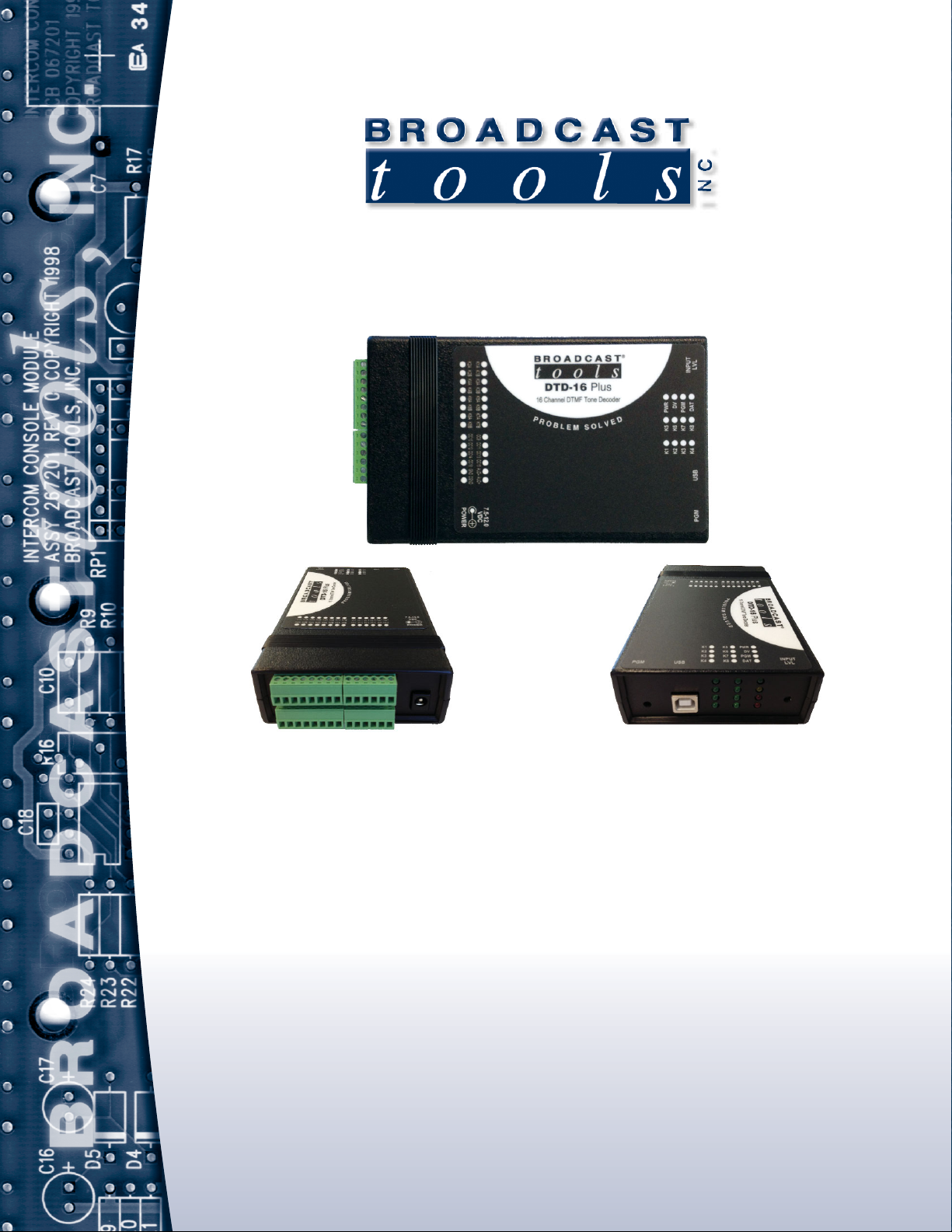
DTD-16 Plus
16 channel DTMF Tone/Sequence Decoder Installation Manual
INC
®
Page 2

DTD-16 Plus Installation and Operation Manual
Table of Contents
Section Title Page #
Introduction . . . . . . . . . . . . . . . . . . . . . . . . . . . . . . . . . . . . . . . . . . . . . 3
Safety Information . . . . . . . . . . . . . . . . . . . . . . . . . . . . . . . . . . . . . . . . 3
Who to Contact for Help . . . . . . . . . . . . . . . . . . . . . . . . . . . . . . . . . . . 3
Product Overview . . . . . . . . . . . . . . . . . . . . . . . . . . . . . . . . . . . . . . . . 4
Features . . . . . . . . . . . . . . . . . . . . . . . . . . . . . . . . . . . . . . . . . . . . . . . . 4
Inspection . . . . . . . . . . . . . . . . . . . . . . . . . . . . . . . . . . . . . . . . . . . . . . . 4
Installation . . . . . . . . . . . . . . . . . . . . . . . . . . . . . . . . . . . . . . . . . . . . . . 4
Surge Protection / RF suppresion . . . . . . . . . . . . . . . . . . . . . . . . . . 4
Input connection . . . . . . . . . . . . . . . . . . . . . . . . . . . . . . . . . . . . . . . 4
Input level control. . . . . . . . . . . . . . . . . . . . . . . . . . . . . . . . . . . . . . 4
Relay connections . . . . . . . . . . . . . . . . . . . . . . . . . . . . . . . . . . . . . . 5
Open Collector connections . . . . . . . . . . . . . . . . . . . . . . . . . . . . . . 5
Dip Switch Settings . . . . . . . . . . . . . . . . . . . . . . . . . . . . . . . . . . . . 5
DTMF Tone Detection Jumper JP1 . . . . . . . . . . . . . . . . . . . . . . . . 5
USB Data output. . . . . . . . . . . . . . . . . . . . . . . . . . . . . . . . . . . . . . . 5
Power and Status LED’s. . . . . . . . . . . . . . . . . . . . . . . . . . . . . . . . . 5
Programming . . . . . . . . . . . . . . . . . . . . . . . . . . . . . . . . . . . . . . . . . . 6
Specifications . . . . . . . . . . . . . . . . . . . . . . . . . . . . . . . . . . . . . . . . . . . . 8
Warranty . . . . . . . . . . . . . . . . . . . . . . . . . . . . . . . . . . . . . . . . . . . . . 9
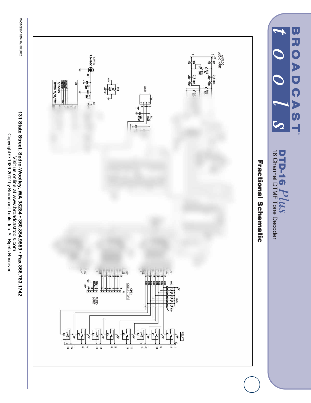
Fractional Schematic . . . . . . . . . . . . . . . . . . . . . . . . . . . . . . . Appendix
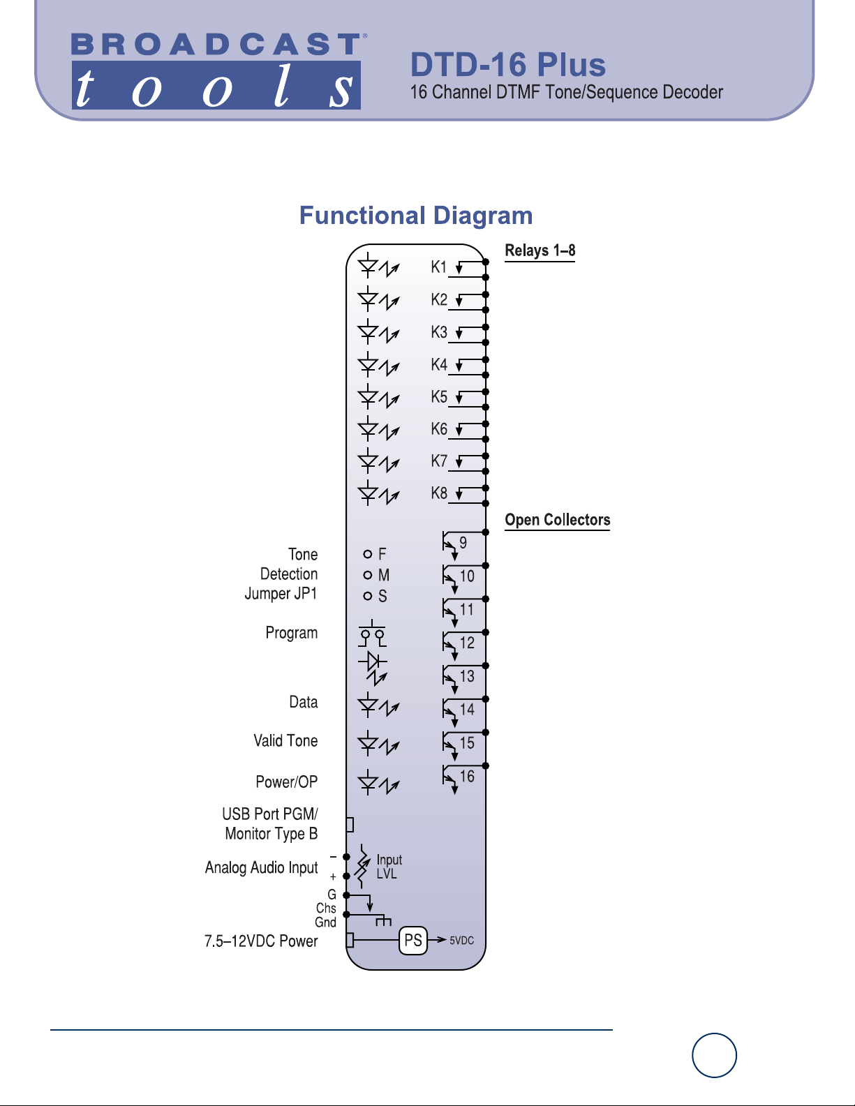
Functional Diagram . . . . . . . . . . . . . . . . . . . . . . . . . . . . . . . . Appendix
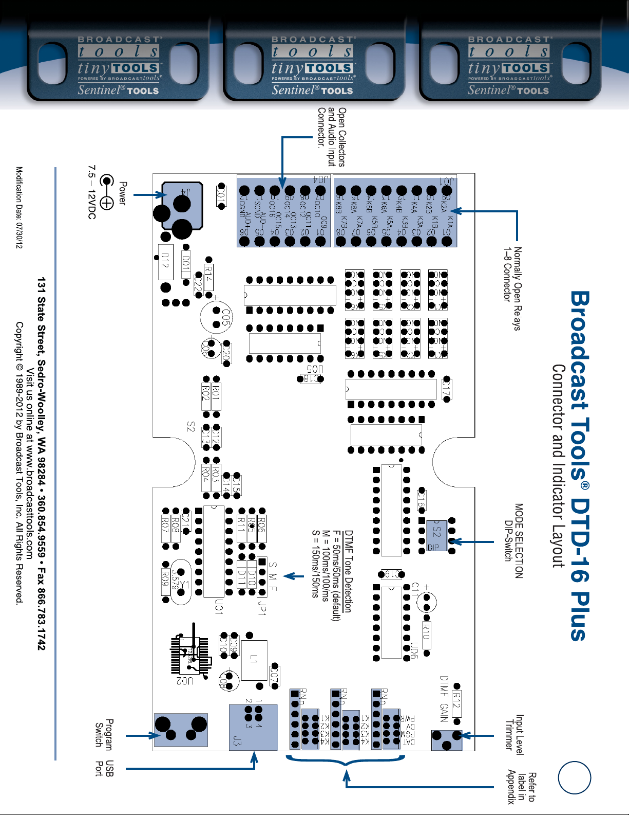
Connector and Indicator Layout . . . . . . . . . . . . . . . . . . . . . . Appendix
Product Label . . . . . . . . . . . . . . . . . . . . . . . . . . . . . . . . . . . . . Appendix
WEBSITE:
Visit our web site for
product updates and
additional information.
2
CONTENTS
Page 3

3
DTD-16 Plus Installation and Operation Manual
INTRODUCTION
INTRODUCTION
Thank you for your purchase of the 16 channel DTMF Tone/Sequence Decoder,
which we will refer to throughout the manual as the DTD-16 Plus. We’re confident
this product will give you many years of dependable service. This manual is intended to give you all the information needed to install and operate the product.
SAFETY INFORMATION
Only qualified technical personnel should install Broadcast Tools products. Any
attempt to install this device by a person who is not technically qualified could result
in a hazardous condition to the installer or other personnel or damage Broadcast
Tools product or other equipment. Please ensure that proper safety precautions have
been taken before installing this device. If you are unfamiliar with this type of
equipment, please contact a properly qualified engineer to handle the installation
and setup of the Broadcast Tools product.
Broadcast Tools, Inc., is unable to support NON-Broadcast Tools software, hardware or
NON-Broadcast Tools computer/hardware/software problems. If you experience these
problems, please research your hardware/software instruction manuals or contact the manufacturers technical support department.
WHO TO CONTACT FOR HELP
If you have any questions regarding your product or you need assistance, please contact your distributor from whom you purchased this equipment.
If you would like more information about Broadcast Tools® products, you may
reach us at:
Broadcast T ools, Inc.
131 State Street
Sedro-Woolley, WA 98284-1503 USA
Voice: 360.854.9559
Fax: 866.783.1742
Internet Home Page: www.broadcasttools.com
E-mail: [email protected]
THANK YOU FOR CHOOSING
BROADCAST TOOLS® BRAND PRODUCTS!
CAUTION!
Broadcast Tools®
Products, as with any
electronic device, can
fail without warning.
Do not use this product
in applications where a
life threatening condition
could result due to failure.
NOTE:
This manual should be
read thoroughly before
installation and operation.
WEBSITE:
Visit our web site for
product updates and
additional information.
Broadcast Tools is a Veteran Owned Business
Designed, Assembled and Supported in WA State, USA
Page 4

4
DTD-16 Plus Installation and Operation Manual
INTRODUCTION
Product Overview
The DTD-16 Plus is a full-featured DTMF tone/sequence decoder that is user programmable to decode single tones or sequences up to six tones in length and maybe
assigned to any one of eight SPST normally open relays, eight open collectors and/or
the USB serial port. The relays and open collectors may be programmed to close for
the duration of tone, pulse immediately after completion of detection, wait a programmed (up to 9.99 seconds) length of time after detection, or latch/unlatch.
Programming is performed using a non-dedicated PC’s USB port equipped with
Windows HyperTerminal and/or Putty.
Features
Decodes all 16 DTMF tones; 16 memory locations; adjustable tone detection time;
line level high Z input, which accepts a balanced or unbalanced source, surge protected power supply, front panel status for power, each relay, valid DTMF tone,
serial data activity, recessed programming push button with LED indicator and
recessed input level control with a range of -20 to +24dbu. All connections are on
removable screw terminals except for the USB Type B female port connector. The
DTD-16 Plus may be set on a desktop, mounted on a wall or up to four units
mounted on the RA-1, 1-RU mounting shelf.
Inspection
Please examine your DTD-16 Plus carefully for any damage that may have been sustained during shipping. If any is noted, please notify the shipper immediately and
retain the packaging for inspection by the shipper. The package contains the DTD-16
Plus, 7.5 to 12 volt DC wall power transformer, four plastic and/or velcro feet,
USB-A/B cable and this manual on the web site or CD.
Installation
Installation of the DTD-16 Plus in high RF environments should be performed with
care. Shielded cable is suggested for all audio connections. All shields should be
tied to the “GND” Ground terminal. The station ground should be connected to the
CGND terminal.
Surge Protection/RF Filtering
It is recommended that all cables connected to the DTD-16 Plus be looped through
ferrite cores to suppress RF. Surge protection with RF filtering such as the Tripp-Lite
“ISOBAR 4 or 6” is also suggested for the wall transformer.
Input Connection
Hi Z, active balanced. Connect your equipment to the AUD- and AUD+ removable
screw terminals. If the user is feeding the unit with an unbalanced output, attach the
positive output to the + input and a jumper between the "-" input and GND
Input level
The front panel “INPUT LVL” control may be used to adjust the DTMF tone detection
from –20dBu to +24dBu. This control should be adjusted for a solid DV led indication.
WEBSITE:
Visit our web site for
product updates and
additional information.
Page 5

5
DTD-16 Plus Installation and Operation Manual
INSTALLATION
Relay connections
The eight relays are Normally Open/dry contacts. Make your connections to the
desired relays K1 A/B thru K8 A/B. Front panel led’s indicate when a relay is active.
Open Collectors Connections
The open collectors are labeled OC9 thru OC16. Make your connection between
the desired open collector and ground “GND”.
NOTE: Each open collector is rated at 12 vdc @ 50 ma.
NOTE: To access the DIP switches and/or jumper, remove all connections and
unscrew the two bottom screws, then open the case. Reverse the action to reassemble.
Dipswitch Setting
DIP-1
If DIP-1 is turned ON; all momentary outputs will become key-follow outputs.
This means that the selected output will turn ON when the last digit of the
momentary code is decoded and stay on for as long as that digit is being decoded.
This is useful for remote pan-tilt camera control.
DIP-2
When DIP-2 is ON, the “#” character will be translated to a CR/LF (0Dh 0Ah) on the
ASCII RS-232 output. This is useful for using DTMF to remotely control equipment
that requires a CR/LF termination. This allows you to use the “#” as an “Enter” key.
DIP-3
When DIP-3 is ON, codes programmed into odd channels, 1,3,5,7, etc., will operate relay one. Even channels, 2,4,6,7, etc., will operate relay 2. Relays 1 and 2 can
be programmed with any mode; momentary, latching or Xlatching.
DIP-4
When DIP-4 is ON, Relays will be engaged on the trailing edge of the DTMF
signal in both momentary and latching modes.
DTMF Tone Detection Jumper JP1
The DTD-16 Plus is equipped with a 4-position jumper, JP1. This is used to adjust
how fast the DTMF tones are detected.
F = Fast, 50ms ON / 50ms OFF. (default)
M = Medium, 100ms ON / 100ms OFF.
S = Slow, 150ms ON / 150ms OFF. To detect multiple tone bursts, the jumper
should be left in the default position F = Fast.
USB data Output
Each DTMF character will be converted to ASCII and outputted to the USB com
port at 9600,8,N,1.
Power
Insert the power plug into the power jack on the DTD-16 Plus and the wall transformer into the proper AC outlet. The power supply MUST be attached to the
power jack to properly power the unit. Verify that the power LED is lit.
WEBSITE:
Visit our web site for
product updates and
additional information.
Page 6

6
DTD-16 Plus Installation and Operation Manual
NOTE:
If DTD-16 Plus’s FTDI
USB Serial “Virtual
COM port” drivers do
not automatically
install they may be
downloaded here:
http://www.ftdichip.com
/Drivers/VCP.htm
WEBSITE:
Visit our web site for
product updates and
additional information.
PROGRAMMING
PROGRAMMING
To program the DTD-16 Plus, you must connect it to the USB port of a PC running
a serial terminal program such as HyperTerminal, or PuTTY. When you first plug
the DTD-16 Plus into your PC it should automatically install the correct FTDI USB
Serial port drivers which will allow you to access the DTD on a COM port. Set the
terminal program to 9600,8,N,1, flow control to NONE. Character Echo should also
be turned ON.
There are two methods of entering program mode. Either press the recessed “PGM”
button or send an ASCII “P” to the USB serial port. Once program mode is entered,
the “PGM” LED will begin to flash and current data will be displayed.”
01-0-0.00-1111/
02-0-0.00-2222/
03-0-0.00-3333/
04-0-0.00-4444/
05-0-0.00-5555/
06-0-0.00-6666/
07-0-0.00-7777/
08-0-0.00-8888/
09-0-0.00-9999/
10-0-0.00-0000/
11-0-0.00-****/
12-0-0.00-####/
13-0-0.00-AAAA/
14-0-0.00-BBBB/
15-0-0.00-CCCC/
16-0-0.00-DDDD/
EXIT PGM
DTD-16+ VER 2.00
(The factory default has multiple digits corresponding to each output, 1111 for
1, 2222 for 2, etc. Example: If relay one is set to 1234 and relays 2,3,4 were left
alone then they would also fire with the 234. Output 10 is DTMF zero, 11 = *, 12
= #, 13 = A, 14 = B, 15 = C, 16 = D. These default values may be reloaded at any
time by removing power from the DTD-16 Plus, holding down the PGM button
and plugging in the power. Release the PGM button after a few seconds. The PGM
LED will blink once after the defaults are loaded.) Default time delay before
activation is 0.00 seconds.
To program, enter the output number 01 through 16. The “-“(dash) will be displayed
after the numbers are entered along with a new line. Next, enter a single command
digit: “0” for momentary, “1” for Latch or “2” for Exclusive Latch.
The “-“(dash) will be displayed after the command digit and a new line will be
displayed. Then enter a time delay value of 0.00 to 9.99 seconds. Do not enter the
".", it will be entered automatically. This is the time that will elapse after a command
is received and the output is activated. Now enter the code you want to use to
operate the selected output.
Page 7

7
DTD-16 Plus Installation and Operation Manual
PROGRAMMING
Momentary
If you have selected the momentary function for this output channel, you can enter two
codes up to 5 digits for the first code and 6 digits for the second code that can be used to
activate that output. If your code is shorter than 5 digits enter a “/” at the end of the first
data string. This will cause a new line to be displayed. Enter the second code you want
to momentarily trigger. If the string is less than 6 digits press the “Enter” key. The codes
for that output will now be saved and you can go on to programming another output.
Momentary Example:
Momentary Example: To program output 1 for momentary for code 123 and 321 with a
time delay of 4.25 seconds before activation:
01-
0
4.25
123/
321(CR)
Latch
For the Latch Function, the first code will be used to latch the output on, and the second code to turn it off. Enter the “ON” code, from 1 to 6 digits. If it is shorter than 5
digits, terminate with the “/” character. A new line will be displayed. Now enter the code
you want to use to turn OFF that output. It must be from 1 to 6 digits long. If it is shorter than 6 digits terminate with the “Enter” key. You cannot enter the same code to latch
an output on and turn it off.
Latch Example:
To program output 2 for 456 latch on, 654 latch off with no time delay:
02
1
0.00
456/
654
Exclusive Latch
For the Exclusive Latch function, the first code will be used to latch the output on,
and the second code to turn it OFF, if desired. You do not need to enter an OFF code.
In Exclusive latch mode, when any exclusive latch output is selected, all other exclusive
latch outputs will be reset. Enter the “ON” code, from 1 to 5 digits. If it is shorter than
6 digits terminate with the “/” character. A new line will be displayed. Now enter the
code you want to use to turn off that output. It must be from 1 to 6 digits long. If it is
shorter than 5 digits terminate with the “Enter” key. You cannot enter the same code to
latch an output on and turn it OFF.
Exclusive Latch Example:
To program output 3 for 789 xlatch on with time delay of .10 second:
02
2
0.10
789(CR)
To exit Program mode, press the ESC key. Also, program mode will be exited after 60 seconds of inactivity. When Program mode is exited, it will list the current values and perform a reset.
WEBSITE:
Visit our web site for
product updates and
additional information.
Page 8

8
DTD-16 Plus Installation and Operation Manual
SPECIFICATIONS
Specifications
Input Level: -20dBu to +24dBu.
Input Impedance: 200K Ω balanced, 100K Ω unbalanced.
Relays: Eight SPST, normally open. 30Vdc@1 amp.
Open Collectors: Eight, 12 Vdc / 50 ma. each
USB Serial: 9600, 8,N,1 / USB type B female.
Connectors: Audio Inputs, relays and open collector outputs.
Removable screw terminals.
Required power supply: 7.5 to 12.0 VDC only @ greater than 400 ma. 2.1mm ID
x 5.5mm OD coaxial connector, center positive, internally surge protected. Domestic PS supplied.
Operating Temperature: -40°F to +185°F (-40°C to +85°C)
Size: 6.18” x 3.70” x 1.42” (L,W,H)
Weight: 1.5 lb.
Options: CE certified universal power supply.
RA-1, 1-RU rack shelf. Note: Velcro may be used to
secure the product to the RA-1 shelf.
WEBSITE:
Visit our web site for
product updates and
additional information.
Page 9

9
DTD-16 Plus Installation and Operation Manual
LIMITED WARRANTY
LIMITED WARRANTY
The term “Buyer” as used in this document refers to and includes both (but only) (a) any person or entity who acquires such an item for
the purpose of resale to others (i.e., a dealer or distributor of an item), and (b) the first person or entity who acquires such an item for
such person’s or entity’s own use. Broadcast Tools warrants to each Buyer of any item manufactured by Broadcast Tools that the item
will be free from defects in materials and workmanship at the time its is shipped by Broadcast Tools if the item is properly installed, used
and maintained.
EXCLUSIVE REMEDIES
If Broadcast Tools is notified of in writing of a failure of any item manufactured by Broadcast Tools to conform to the foregoing Limited
Warranty within one (1) year following the date of the Buyer’s acquisition of the item, and if the item is returned in to Broadcast Tools in
accordance with Broadcast Tools’ instructions for confirmation by inspection of the defect (which at Broadcast Tools’ election may
include, without limitation, a requirement that the Buyer first obtain a Return Authorization number from Broadcast Tools, that the Buyer
furnish proof of purchase in the form of an invoice and/or receipt, and that the Buyer prepay all freight charges associated with any return
of the item to Broadcast Tools using such freight service as Broadcast Tools reasonably may specify), Broadcast Tools will repair or
replace the defective item, or will refund the purchase price paid by the Buyer for the item. Broadcast Tools shall have the exclusive
right to choose between these alternative remedies.
NO OTHER WARRANTIES OR REMEDIES
TO THE MAXIMUM EXTENT PERMITTED BY APPLICABLE LAW, Broadcast Tools AND ITS SUPPLIERS DISCLAIM ALL OTHER
WARRANTIES, EITHER EXPRESS OR IMPLIED, INCLUDING BUT NOT LIMITED TO IMPLIED WARRANTIES OF MERCHANTABILITY OR FITNESS FOR A PARTICULAR PURPOSE; AND THE FOREGOING ALTERNATIVE REMEDIES SHALL BE EXCLUSIVE OF
ALL OTHER REMEDIES. THIS LIMITED WARRANTY GIVES YOU SPECIFIC LEGAL RIGHTS. YOU MAY HAVE OTHER RIGHTS,
WHICH VARY FROM STATE/JURISDICTION TO STATE/JURISDICTION. NO LIABILITY FOR CONSEQUENTIAL DAMAGES TO THE
MAXIMUM EXTENT PERMITTED BY APPLICABLE LAW, NEITHER Broadcast Tools NOR ANY OF ITS SUPPLIERS SHALL HAVE ANY
LIABILITY FOR ANY SPECIAL, INCIDENTAL, INDIRECT, CONSEQUENTIAL OR PUNITIVE DAMAGES WHATSOEVER (INCLUDING,
WITHOUT LIMITATION, ANY DAMAGES FOR LOST PROFITS, BUSINESS INTERRUPTION, LOSS OF DATA OR INFORMATION,
COST OF CAPITAL, CLAIMS OF CUSTOMERS, OR ANY OTHER PECUNIARY LOSS) ARISING OUT OF THE USE OF OR THE
INABILITY TO USE ANY ITEM SUPPLIED BY Broadcast Tools), EVEN IF Broadcast Tools HAS BEEN ADVISED OF THE POSSIBILITY OF SUCH DAMAGES HAVE ANY LIABILITY FOR ANY SPECIAL, INCIDENTAL, CONSEQUENTIAL, EXEMPLARY OR PUNITIVE
DAMAGES. THIS LIMITATION OF LIABILITY APPLIES WHETHER A CLAIM IS ONE ALLEGING BREACH OF A CONTRACT OR WARRANTY, NEGLIGENCE OR OTHER TORT, FOR THE VIOLATION OF ANY STATUTORY DUTY, THE FAILURE OF ANY LIMITED OR
EXCLUSIVE REMEDY TO ACHIEVE ITS ESSENTIAL PURPOSE, OR ANY OTHER CLAIM OF ANY NATURE. BECAUSE SOME
STATES AND JURISDICTIONS DO NOT ALLOW THE EXCLUSION OR LIMITATION OF LIABILITY FOR INCIDENTAL OR CONSEQUENTIAL DAMAGES, THIS LIMITATION MAY NOT APPLY TO YOU.
Broadcast T ools, Inc.
131 State Street
Sedro-Woolley, WA 98284 • USA
360.854.9559
voice • 866.783.1742 fax
[email protected] e-mail
www.broadcasttools.com website
Page 10
DTD-16 Plus Installation and Operation Manual
10
APPENDIX
Page 11
DTD-16 Plus Installation and Operation Manual
11
APPENDIX
Page 12
DTD-16 Plus Installation and Operation Manual
12
APPENDIX
Page 13
13
DTD-16 Plus Installation and Operation Manual
APPENDIX
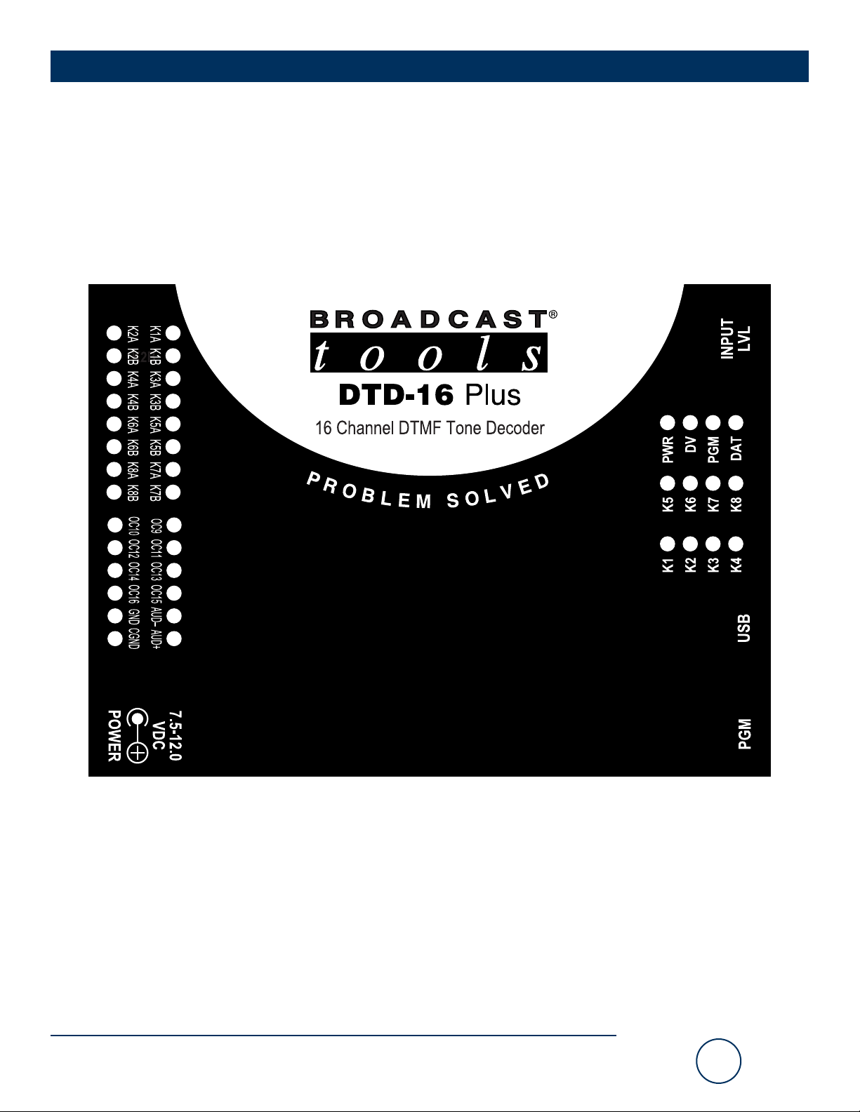
Product Label
 Loading...