

Page 1
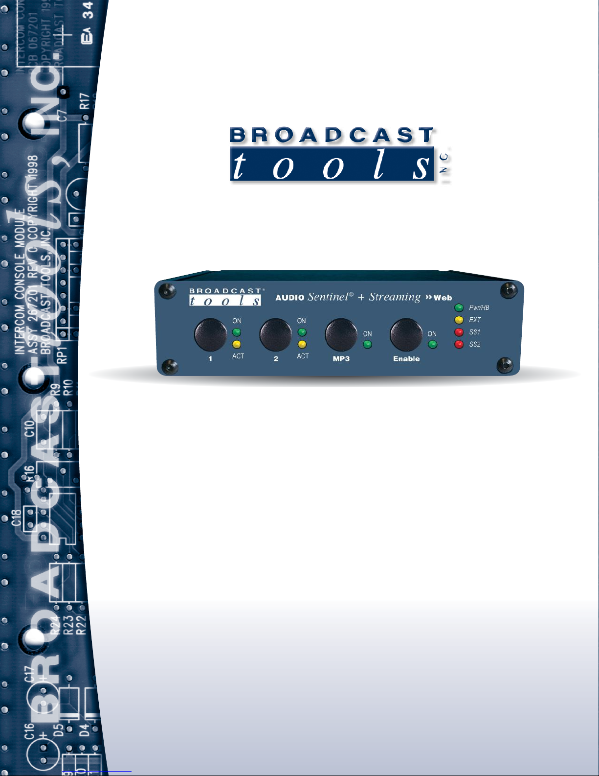
Installation and Operation Manual
PROBLEM SOLVED
Due to the dynamic nature of product design, the information contained in this
document is subject to change without notice. Broadcast Tools, Inc., assumes no
responsibility for errors and/or omissions contained in this document. Revisions
of this information or new editions may be issued to incorporate such changes.
Broadcast To ols® is a registered t rademark of Broadcast Tools, Inc.
All Sentinel™ labeled products are a trademark of Broadcast Tools, Inc.
Copyright ® 1989 - 2015 by Broadcast Tools, Inc. All rights reserved.
No part of this document may be reproduced or distributed without permission.
Visit www.broadcasttools.comfor important product update information.
Manual update: 12/8/2014
Firmware Version 1.19 and above
If you need a firmware upgrade, contact Broadcast Tools®
No part of this document may be reproduced or distributed without permission.
ALL SPECIFICATIONS AND FEATURES FOR THIS PRODUCT ARE SUBJECT TO
CHANGE WITHOUT NOTICE
NOTE: We recommend the use of Chrome, Firefox or Safari as your browser.
Audio Sentinel + Streaming
Web based dual channel stereo silence monitor with streaming.
INC
®
Page 2

Audio Sentinel®+ Streaming Installation and Operation Manual
Table of Contents
Section Title . . . . . . . . . . . . . . . . . . . . . . . . . . . . . . . . . . Page #
Introduction . . . . . . . . . . . . . . . . . . . . . . . . . . . . . . . . . . . . . . . . . . . . . 3
Safety Information . . . . . . . . . . . . . . . . . . . . . . . . . . . . . . . . . . . . . . . . 3
Who to Contact for Help . . . . . . . . . . . . . . . . . . . . . . . . . . . . . . . . . . . 3
Product Overview . . . . . . . . . . . . . . . . . . . . . . . . . . . . . . . . . . . . . . . . 4
Features/Benefits . . . . . . . . . . . . . . . . . . . . . . . . . . . . . . . . . . . . . . . . . 4
Inspection . . . . . . . . . . . . . . . . . . . . . . . . . . . . . . . . . . . . . . . . . . . . . . . 5
Installation/Operation. . . . . . . . . . . . . . . . . . . . . . . . . . . . . . . . . . . . . . 5
Surge Protection. . . . . . . . . . . . . . . . . . . . . . . . . . . . . . . . . . . . . 5
UPS standby power system . . . . . . . . . . . . . . . . . . . . . . . . . . . . 5
LED indicators. . . . . . . . . . . . . . . . . . . . . . . . . . . . . . . . . . . . . . 6
Front Panel Controls . . . . . . . . . . . . . . . . . . . . . . . . . . . . . . . . . 6
Audio Inputs/Outputs . . . . . . . . . . . . . . . . . . . . . . . . . . . . . . . . 6
Relay and Remote Control Connections . . . . . . . . . . . . . . . . . . 7
Ethernet . . . . . . . . . . . . . . . . . . . . . . . . . . . . . . . . . . . . . . . . . . . 7
Power . . . . . . . . . . . . . . . . . . . . . . . . . . . . . . . . . . . . . . . . . . . . . 7
Chassis ground . . . . . . . . . . . . . . . . . . . . . . . . . . . . . . . . . . . . . 7
Ethernet “Quick Start” Guide . . . . . . . . . . . . . . . . . . . . . . . . . . . . . . . 8
Opening the LOGIN Web Page . . . . . . . . . . . . . . . . . . . . . . . . . . . . . 12
Web Setup/Operation . . . . . . . . . . . . . . . . . . . . . . . . . . . . . . . . . . . . . 13
“Login” Web Page . . . . . . . . . . . . . . . . . . . . . . . . . . . . . . . . . 14
“Monitor/Control” Web Page . . . . . . . . . . . . . . . . . . . . . . . . . 16
“User Setup” Web Page . . . . . . . . . . . . . . . . . . . . . . . . . . . . . 17
“I/O Setup” Web Page . . . . . . . . . . . . . . . . . . . . . . . . . . . . . . . 14
“Email/Network Setup” Web Page . . . . . . . . . . . . . . . . . . . . . 19
“Show Log” Web Page . . . . . . . . . . . . . . . . . . . . . . . . . . . . . . 25
“About” Web Page. . . . . . . . . . . . . . . . . . . . . . . . . . . . . . . . . . 26
Specifications . . . . . . . . . . . . . . . . . . . . . . . . . . . . . . . . . . . . . . . . . . . 27
Warranty. . . . . . . . . . . . . . . . . . . . . . . . . . . . . . . . . . . . . . . . . . . . . . . 28
Front and rear panel drawings . . . . . . . . . . . . . . . . . . . . . . . . Appendix
Connector, configuration jumpers and dip-switch layout . . . Appendix
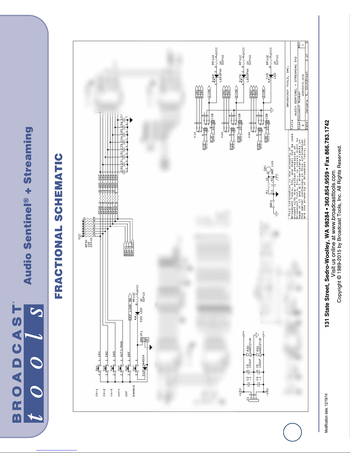
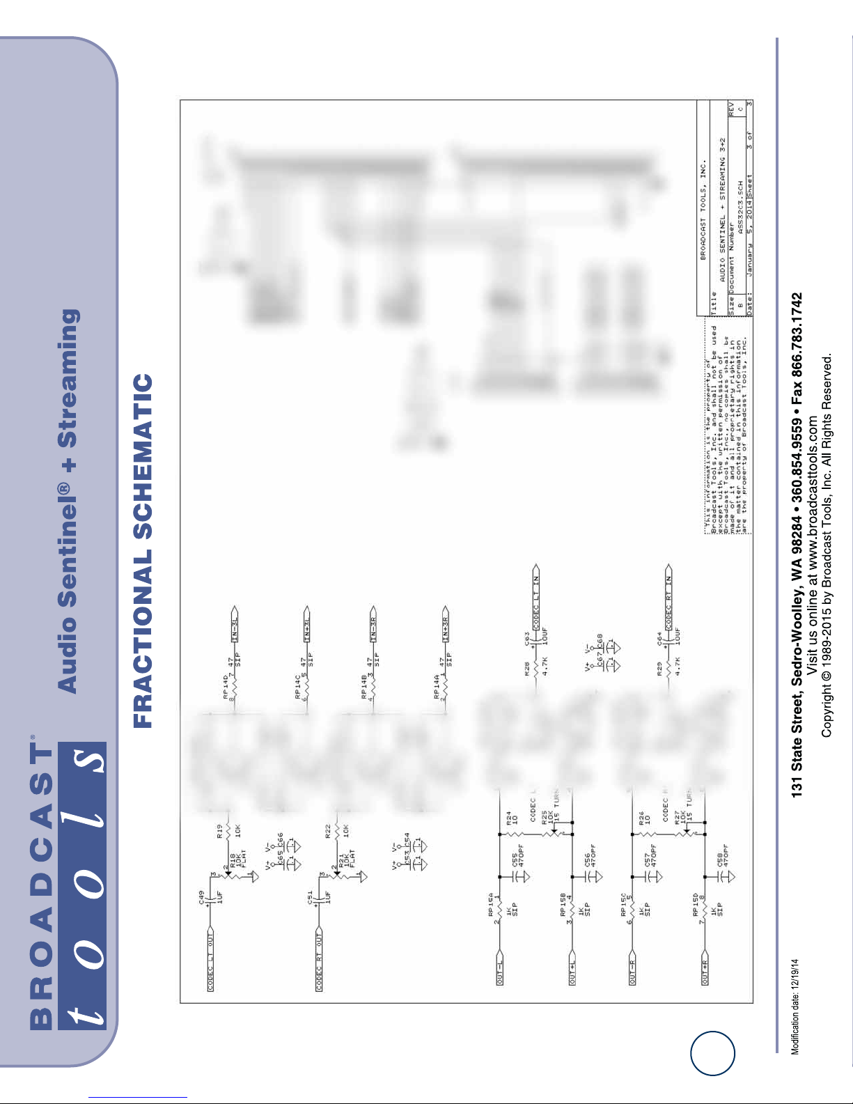
Fractional schematic . . . . . . . . . . . . . . . . . . . . . . . . . . . . . . . Appendix
WEBSITE:
Visit our web site for
product updates and
additional information.
2
CONTENTS
Page 3

3
Audio Sentinel®+ Streaming Installation and Operation Manual
INTRODUCTION
INTRODUCTION
Thank you for your purchase of a BROADCAST TOOLS® AUDIO
SENTINEL + STREAMING four channel internet radio monitor. We’re confident that this product will give you many years of dependable service. This
manual is intended to give you all the information needed to install and operate
the BROADCAST TOOLS® AUDIO SENTINEL + STREAMING.
SAFETY INFORMATION
Only qualified technical personnel should install the AUDIO SENTINEL +
STREAMING. Any attempt to install this device by a person who is not technically qualified could result in a hazardous condition to the installer or other personnel
or damage to the AUDIO SENTINEL + STREAMING or other equipment. Please
ensure that proper safety precautions have been taken before installing this device.
If you are unfamiliar with this type of equipment, please contact a properly qualified
engineer to handle the installation and setup of the AUDIO SENTINEL +
STREAMING. Broadcast Tools, Inc., is unable to support NON-Broadcast Tools
software, hardware or NON-Broadcast Tools computer/hardware/software problems. If you experience these problems, please research your hardware/software
instruction manuals or contact the manufacturers technical support department.
WHO TO CONTACT FOR HELP
If you have any questions regarding your product or you need assistance, please contact your distributor from whom you purchased this equipment. If you would like
more information about BROADCAST TOOLS® products, you may reach us at:
Broadcast Tools, Inc.
131 State Street
Sedro-Woolley, WA 98284-1503 USA
Voice: 360.854.9559
Fax: 866.783.1742
Internet Home Page: www.broadcasttools.com
E-mail:[email protected]
THANK YOU FOR CHOOSING
BROADCAST TOOLS® BRAND PRODUCTS!
CAUTION!
Broadcast Tools®
Products, as with any
electronic device, can
fail without warning.
Do not use this product
in applications where a
life threatening condition
could result due to failure.
NOTE:
This manual should be
read thoroughly before
installation and operation.
WEBSITE:
Visit our web site for
product updates and
additional information.
Page 4

4
Audio Sentinel®+ Streaming Installation and Operation Manual
OVERVIEW
Product Overview
The AUDIO SENTINEL + STREAMING is a web-enabled two channel stereo
silence monitor combined with a transparent, integrated stereo audio switcher, and
MP3 streaming codec for confidence monitoring over the internet. AUDIO SENTINEL + STREAMING is designed to monitor two balanced or unbalanced independent stereo analog audio sources and switch to a back-up analog audio source
when silence is detected on either or both input channels. The AUDIO SENTINEL
+ STREAMING may also be configured for independent dual-stereo non-switching
applications. The AUDIO SENTINEL + STREAMING can be controlled and monitored locally and/or remotely over any IP network, including private networks, IPbased industrial control networks, and the Internet. Users can operate the product
using a web browser or web-enabled mobile device. Email notifications may be
configured to alert up to 8 recipients when alarms are detected. The user may also
enable a sound effect to play on their PC speaker when an alarm is generated while
logged in. Logging of system status, along with the site ID may be emailed in time
spans from once an hour to once a day. Two SPDT relays are supplied to indicate
which input channel is feeding the output, while two open collector outputs are provided to indicate input alarm status.
Features/Benefits
• Built-in web server provides simple, web based notification, monitoring, configuration, control.
• Internal silence sensor with front panel activity and alarm LED indicators.
• MP3 streaming codec for web based output audio confidence monitoring.
• Front panel, remote, and web-based switcher controls.
• Silence trip level detection from -24dB to -35dB in 1 dB steps for each stereo
channel.
• Precise alarm time delay from 0(OFF) to 65535 seconds (18 hours, 12 min and
15 sec’s). in one-second increments for each channel.
• Alarm restore time delay from 0(OFF) to 65535 seconds (18 hours, 12 min and
15 sec’s). in one-second increments for each channel.
• Email notification may be configured to alert up to EIGHT recipients when
alarms are detected.
• Email logging of system status, along with the site ID may be emailed in time
spans from once an hour to once a day.
• Support for STARTTLS secure SMTP authentication (Gmail.)
• Removable euroblock-style screw terminal connectors simplify wiring and
service. Mating
• plugs are supplied.
• Fully RFI proofed.
• Surge protected internal power supply, PS-1515 universal switching +/-15VDC
power supply with domestic connectors supplied. International AC connectors
optional.
• Up to three units may be mounted on the optional RA-1 rack shelf. Desktop and
wall mounting is also possible.
WEBSITE:
Visit our web site for
product updates and
additional information.
Page 5

5
Audio Sentinel®+ Streaming Installation and Operation Manual
INSTALLATION
Inspection
Please examine your AUDIO SENTINEL + STREAMING carefully for any damage that may have been sustained during shipping. If any damage is present, please
notify the shipper immediately and retain the packaging for inspection by the shipper. The package should contain the AUDIO SENTINEL + STREAMING, and a +/15 VDC wall power supply with domestic connector. Manuals may be downloaded
from our web site.
Installation
Surge Protection
The AUDIO SENTINEL + STREAMING has built-in resistance to voltage changes;
we recommend that you use a power surge protector or line conditioner on the
incoming AC line. Lightning strikes and/or other high voltage surges may damage
your AUDIO SENTINEL + STREAMING and connected equipment if it is not
properly protected. For lightning protection devices, check out
www.polyphaser.com and www.itwlinx.com.
UPS Standby Power System
We recommend that you connect your AUDIO SENTINEL + STREAMING to a
UPS system. A UPS helps minimize the risk to the AUDIO SENTINEL + STREAMING and provides power during a power outage.
WEBSITE:
Visit our web site for
product updates and
additional information.
Page 6

6
Audio Sentinel®+ Streaming Installation and Operation Manual
INSTALLATION
LED indicators
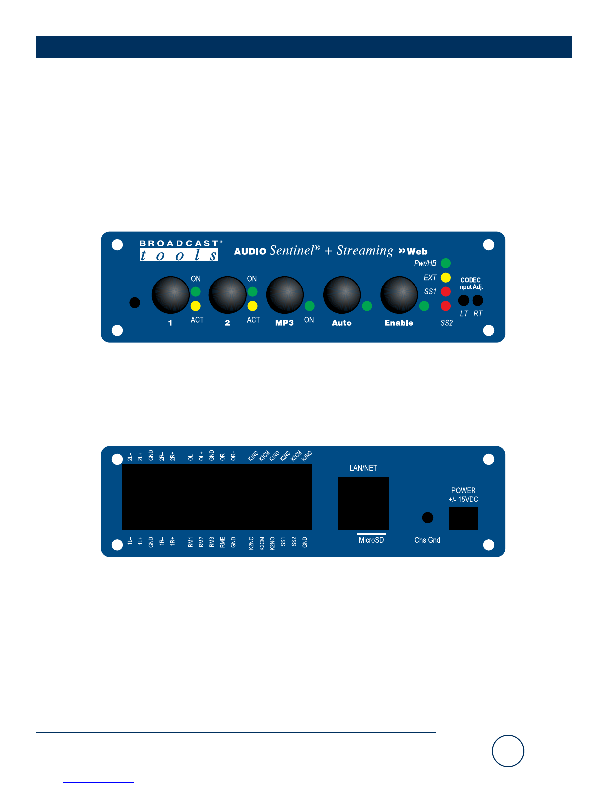
• “Pwr/HB” LED: Illuminates when power is applied and flashes to indicate
microprocessor operation. (Green)
• “EXT” LED: Lit when EXTernal alarm input is active. (Yellow)
• “SS1” LED: Lit when silence is detected on Input 1. (Red)
• “SS2” LED: Lit when silence is detected on Input 2. (Red)
• “Auto” LED: Lit when in automatic switching mode, in manual mode when not
lit. (Green)
• “Enable” LED: Illuminates when the front panel enable push button option is enabled.
• “ON” LEDs: Lit when input is routed to output. (Green)
• “ACT” LEDs: Lit when input audio is above threshold. (Yellow)
Front Panel Controls
“1” and “2” pushbuttons: Used to select which input is routed to the output when in
Manual mode. Each push button has an associated LED indicator, which will illuminate when that particular channel is selected. When a channel is selected, the previous channel is deselected (interlock).
“Auto” pushbutton: Used to toggle between automatic and manual switching modes.
“Enable” pushbutton: The enable (safety) push button can be enabled to require the
user to hold down the enable push button while selecting any of the other front panel
push buttons, the enable LED is illuminated when this function is enabled
Audio Input Connections
Connect your audio sources to either of the two stereo balanced channels. For
unbalanced inputs, connected the high side of the source to the (+) positive input and
the shield along with a jumper between the “–” input and GND terminals. Single
(monaural) input sources should have their left and right inputs connected in parallel. Proper phasing must be observed.
Audio Output Connections
Connect the load to the terminals labeled “OL–/+ CM and OR–/+ CM. For
unbalanced loads, use the “+” and GND terminals only. Shields should be tied to
the “GND” terminals.
NOTE: The switching function is not required for proper ope
WEBSITE:
Visit our web site for
product updates and
additional information.
Input 1
(Top row, TB1)
2L- 2L+ Gnd 2R- 2R+
1L- 1L+ Gnd 1R- 1R+
Input 2
(Bottom row, TB1)
Output
(Top row, TB3)
OL- OL+ Gnd OR- OR+
See Remote Control Input Connections
(Bottom Row, TB3)
Page 7

7
Audio Sentinel®+ Streaming Installation and Operation Manual
INSTALLATION
Remote Control Input Connections
The Audio Sentinel + Streaming has for four remote control inputs that and accept momentary contact closures, open collector, or TTL/CMOS input logic levels. Each input is pulled
high (5-volts) through a 22K resistor and is considered active/on when pulled low to ground.
For example; pulsing the “RM2” input to ground would switch the Audio Sentinel +
Streaming to Input 2 when in Manual switching mode.
The “RME” (external) can be configured for either toggle or sustained closure control. In
toggle mode each time this input is pulled to ground, the unit toggles between channels one
and two. In sustained mode the RME input will immediately trigger and switch to the backup source. This may be used to monitor STL or satellite squelch relay, etc.
Each remote control channel is pulled high (5-volts) through a 22K resistor.
Relay and Open Collector Connections
The K1, K2 and K3 SPDT relays provide switch position tallies for the Audio Sentinel +
Streaming. K1 is closed when Input 1 is switched to the output, K2 is closed when input 2
is switched to the output.
The Audio Sentinel + Streaming has two open collector outputs that are used to indicate
input silence alarm status. The SS1 OC indicates for Input 1 and the SS2 OC indicates for
Input 2. The open collector output will go low providing a return for an LED indicator,
TTL/CMOS logic or relay. External pull-up resistors may be required in some installations,
voltages must be limited to 6 VDC at 600 mA.
LAN / NET Jack
RJ45 Ethernet jack for 10/100baseT LAN/WAN connection.
MicroSD Card Slot
MicroSD memory card slot. Used for file storage and software updates via user-supplied
MicroSD card.
Chassis Ground (Chs Gnd)
Tie to station ground system.
Power
Connect the supplied PS-1515 +/-15 VDC switching power supply’s 3-pin AMP-style latching power connector to the unit and the power supply with domestic connector into a 120
Vac 50-60 Hz power source. International AC input power plug adapters are optional.
NOTE: Never use any type of power supply other than the specified/supplied
power supply.
WEBSITE:
Visit our web site for
product updates and
additional information.
(Top row, TB2)
RM1 RM2 RM3 RME GND
(Input 1) (Input 2) (EXTernal)
Remote Control Inputs
(Bottom Row, TB2)
(TB3 Top)
K1NC K1CM K1NO K3NC K3CM K3NO
(IN1 Tally) (IN1 Tally) (IN1 Tally) (IN3 Tally) (IN3 Tally) (IN3 Tally)
K2NC K2CM K2NO SS1 OC SS2 OC GND
(IN2 Tally) (IN2 Tally) (IN2 Tally)
(TB3 Bottom)
Page 8

8
Audio Sentinel®+ Streaming Installation and Operation Manual
SETUP
CAUTION!
CAUTION! Never
download firmware
updates unless instructed to do so by
Broadcast Tools®.
Doing so deletes all
software and voids all
warranties from broadcast tools®, inc.
NOTE:
We recommend the use
of the latest version of
Firefox, Safari for
Windows or Chrome as
your browser.
WEBSITE:
Visit our web site for
product updates and
additional information.
Web Setup and Operation
Ethernet “Quick Start” guide
CAUTION! If you are not familiar with Ethernet enabled equipment, it may be useful to contact your IT department, network administrator or network consultant for
assistance. Assigning an IP address already in use by another device may cause
problems with your network!
Instructions for changing the IP address of the computer that will be used for the
configuration of this product are given here. Note that these instructions are specifically for computers with the Windows XP operating system. For setup using other
operating systems, refer to the appropriate OS user’s manual.
Page 9
9
Audio Sentinel®+ Streaming Installation and Operation Manual
SETUP
WEBSITE:
Visit our web site for
product updates and
additional information.
Ethernet “Quick Start” guide (cont).
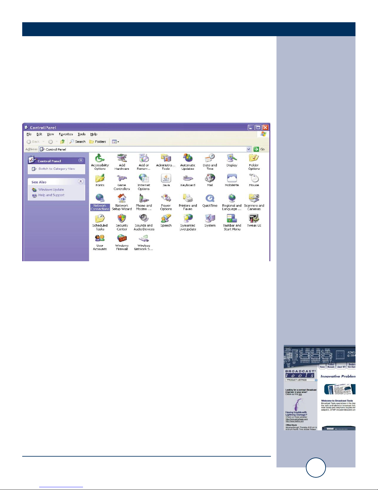
Step 1: Open the control panel by clicking on the start menu, click on settings,
then click on Control Panel. (Note that the control panel shown is in “Classic
View”. If control panel is in “Category View” select the “Classic View” option
before proceeding.)
Step 2: Double click on the icon labeled Network Connections. The following
menu will pop up.
Page 10
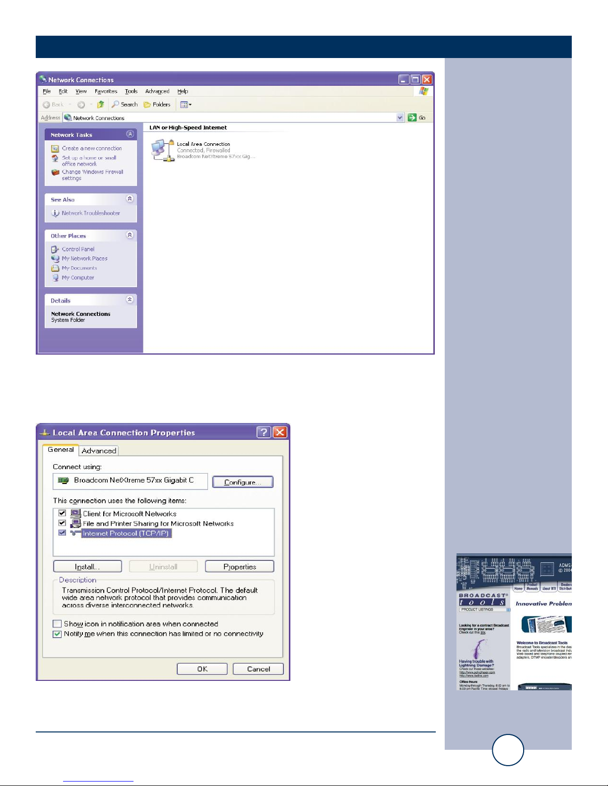
Step 3: Right click on the icon labeled Local Area Connection. Another menu will
appear. Select the option at the bottom of the menu labeled Properties. The Local
Area Connection Properties window will appear.
Step 4: On the Local Area Connection Properties page, double click on Internet
Protocol (TCP/IP) to display properties.
10
Audio Sentinel®+ Streaming Installation and Operation Manual
SETUP
WEBSITE:
Visit our web site for
product updates and
additional information.
Page 11
11
Audio Sentinel®+ Streaming Installation and Operation Manual
SETUP
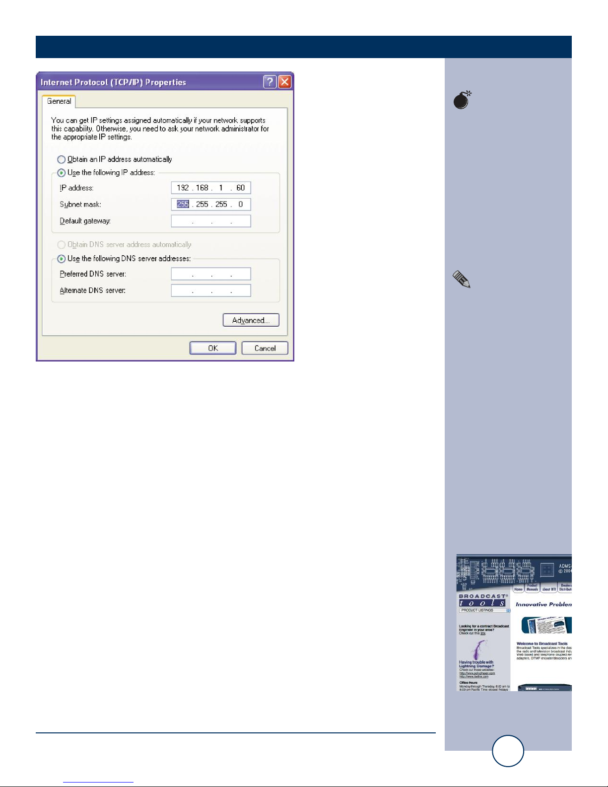
Step 5: Before making any changes to the network settings, write down the current
settings (or screen capture the page and print) so that they can be restored once the
unit is configured. Next, select the radio button labeled “Use the following IP
address” and type in the IP address 192.168.1.60. Type in the subnet mask of
255.255.255.0. Leave the default gateway field blank. Click OK to apply the new
settings.
!
TIP
Helpful tips area.
CAUTION!
Broadcast Tools
products, as any electronic device, can fail
...
NOTE:
For safety, DO NOT
connect ...
WEBSITE:
Visit our web site for
product updates and
additional information.
Page 12

12
Audio Sentinel®+ Streaming Installation and Operation Manual
SETUP
Opening the LOGIN Web Page
1. Connect the supplied GRAY colored XOVER cable between the PC’s Ethernet
port and the products “LAN/NET” network RJ45 jack.
2. Connect the supplied power supply to the product’s power jack. Verify that the
front panel green POWER LED is ON and the left “LINK” LED above the “NET”
Network RJ-45 connector is illuminated
Open the product’s login page by typing the following URL into the browser:
http://192.168.1.55 a username and password is required to change any parameter
and are case sensitive.
Factory “login” defaults: username: admin (lower case)
password: 1234
3. Once you are logged in, follow this manual for setup and/or operational information.
WEBSITE:
Visit our web site for
product updates and
additional information.
Page 13
13
Audio Sentinel®+ Streaming Installation and Operation Manual
SETUP
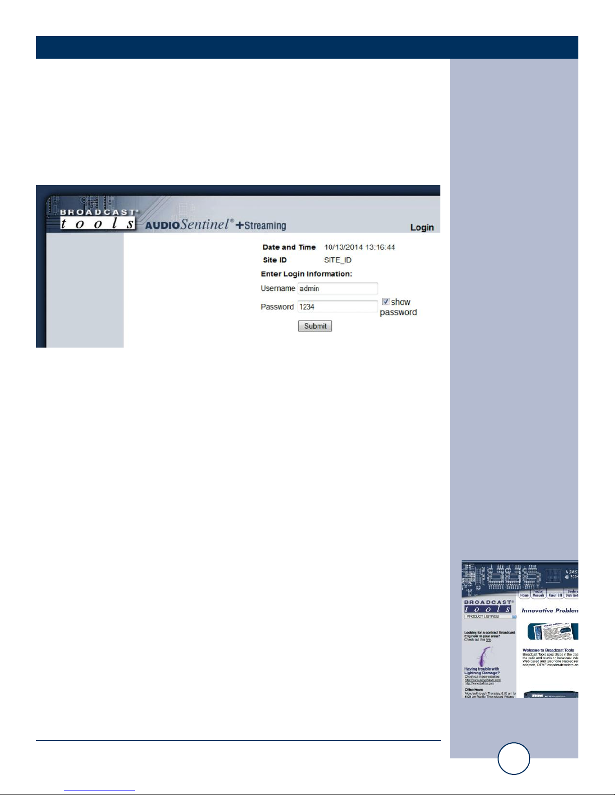
“Login” Web Page
The Login screen displays the Username and Password entry points as well as the
date, time, and site ID.
You may view the password by checking the “Show Password” box.
After you have successfully logged in, the Monitor/Control page will be displayed.
WEBSITE:
Visit our web site for
product updates and
additional information.
Page 14
14
Audio Sentinel®+ Streaming Installation and Operation Manual
SETUP
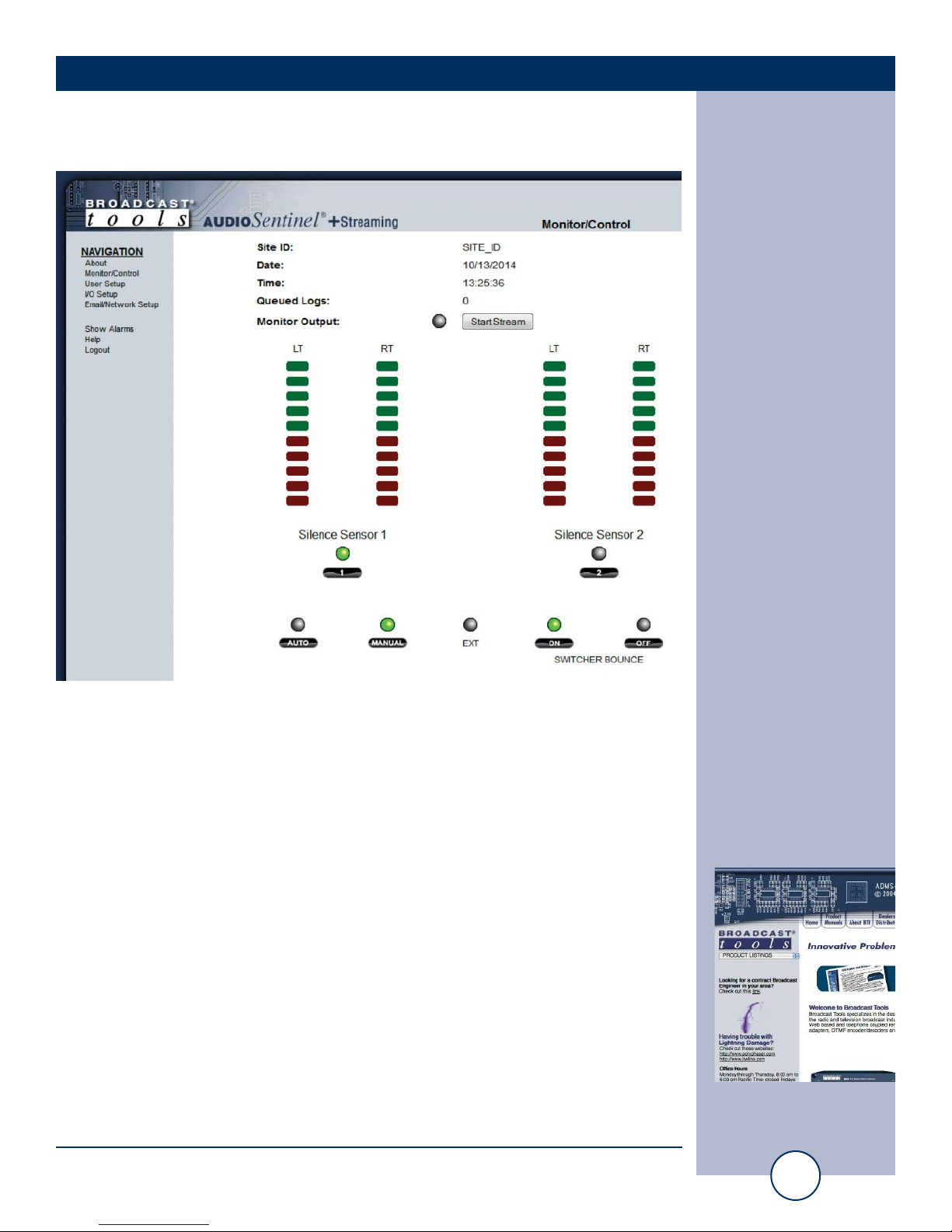
“Monitor/Control” Web Page
The Monitor/Control page allows the monitor and/or control of the Audio Sentinel
+ Streaming. The following is an explanation of each item on this page:
Site ID: Displays user assigned site ID/device name.
Date/Time: Displays date and time from system clock.
Queued Logs: Displays the number of queued log entries scheduled
to be emailed.
Monitor Output: MP3 monitoring stream control. Click “Start Stream”
to monitor output audio. Also available at:
http://192.168.1.55/audio/output.mp3
Left and Right Level LED’s: Display the left and right input levels for inputs one
and two. Green is above the alarm threshold and red is
below.
Input Labels: User defined in the Silence Sensor setup page.
WEBSITE:
Visit our web site for
product updates and
additional information.
Page 15

15
Audio Sentinel®+ Streaming Installation and Operation Manual
SETUP
Input Selection buttons: If the unit is in manual mode, the user may switch
between each input by placing the cursor under each input LED, then click. The
desired input is selected as denoted by the LED being illuminated.
EXT LED: Illuminates when the “SELECT/EXT” input is selected.
AUTO: When this mode is selected, any time input ONE fails,
the unit will switch to input TWO. Manual and
remote operation of the unit is disabled except for
“SUSTAINED” operation. The LED is illuminated
when selected.
MANUAL: Manual mode allows the user to select either input one
or two as well as remote control operation. The manual LED is illuminated when selected.
SWITCHER BOUNCE: Allows the switcher to automatically switch between
inputs when in AUTO mode and valid audio and time
delays have expired.
WEBSITE:
Visit our web site for
product updates and
additional information.
Page 16
16
Audio Sentinel®+ Streaming Installation and Operation Manual
SETUP
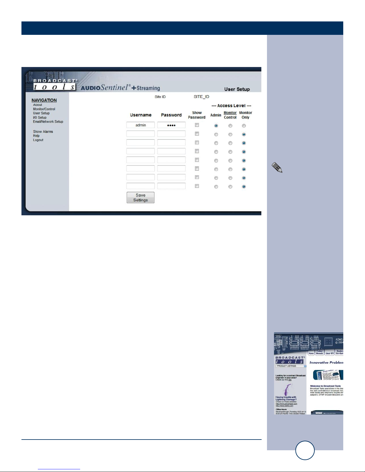
“User Setup” Web Page
Eight Usernames and Passwords may be configured for up to three access levels:
1. “admin” allows complete configuration access and control.
2. “Monitor/Control” allows the following access:
About, Monitor/Control, Show log, Help, and Logout.
3. “Monitor Only” allows the following access:
About, Monitor only, Help, and Logout.
Only users with “admin” access can make changes to this page.
The site ID is displayed and can be changed on the Email/Network Setup page.
NOTE:
After any item has been
changed, you MUST
press the “Save
Settings” button for
your changes to be
saved.
WEBSITE:
Visit our web site for
product updates and
additional information.
Page 17
17
Audio Sentinel®+ Streaming Installation and Operation Manual
SETUP
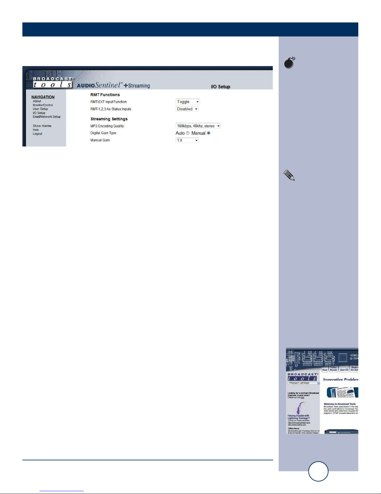
“I/O” Setup Page
RMT Functions
RMT-EXT Input Function: This sets the behavior of the EXTernal (RME) remote
control input. See Remote Control Inputs for more information.
RMT-1,2,3 as Status Inputs: Allows Remote Control inputs 1-3 to be used as status
alarm inputs.
Streaming Settings
MP3 Encoding Quality: Sets bit rate, sample rate, and channels of streaming
audio.
Digital Gain Type: MP3 encoder can be set to manual (fixed) gain or to automatic gain control based on input levels.
Manual Gain/Auto-Gain Range: In Manual mode this sets the MP3 encoder
input gain, the default settings is unity (1X). In Auto mode this sets the automatic
gain control range.
!
TIP
Helpful tips area.
CAUTION!
Broadcast Tools
products, as any electronic device, can fail
...
NOTE:
For safety, DO NOT
connect ...
WEBSITE:
Visit our web site for
product updates and
additional information.
Page 18
18
Audio Sentinel®+ Streaming Installation and Operation Manual
SETUP
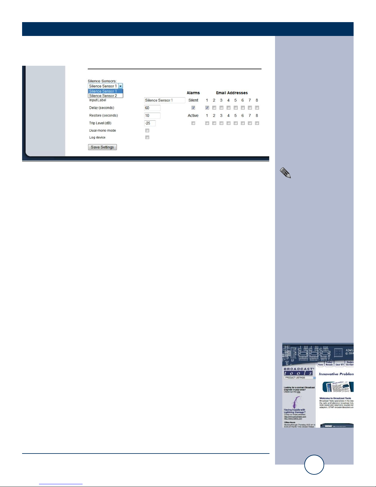
Silence Sensors
Silence Sensors: Use this drop down menu to choose a silence sensor to con-
figure.
Alarms Silent: This option enables the generation of an alarm message when
silence is detected/restored.
Alarms Active: This option enables the generation of an alarm when a chan-
nel is made active via front panel/web controls, automatic
switching, or remote control.
Email Addresses: This allows you to assign up to 8 email addresses to send
alarm emails to whenever the input enters or exits an alarm
state.
Input Label: Text label describing the input source. This is used on the
Monitor/Control page and in alarm log and email messages.
Delay (seconds): Specifies the delay time from when the input value is below
the silence trip level and an alarm is generated.
Restore (seconds): Specifies the delay time from when the input value is returns
to a level above the silence trip level and the alarm condition
is exited.
Trip Level (dB): The input level below which the input is considered silent, in
dB below 0 dBu. Range: -12 to -35 dB.
Dual-mono mode: When dual input mono mode is selected, both the left and
right inputs must be below the trip level before the input is
considered silent.
Log Device: Enables the email snapshot logging of the input.
NOTE:
After any item has been
changed, you MUST
press the “Save
Settings” button for
your changes to be
saved.
WEBSITE:
Visit our web site for
product updates and
additional information.
Page 19
19
Audio Sentinel®+ Streaming Installation and Operation Manual
SETUP
“Email/Network Setup” Web Page
!
TIP
Helpful tips area.
CAUTION!
Broadcast Tools
products, as any electronic device, can fail
...
NOTE:
For safety, DO NOT
connect ...
WEBSITE:
Visit our web site for
product updates and
additional information.
Page 20

20
Audio Sentinel®+ Streaming Installation and Operation Manual
SETUP
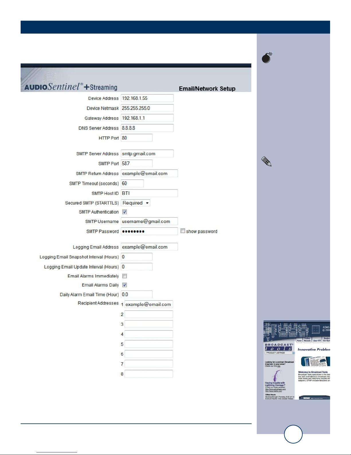
“Email/Network Setup” Web Page – Device Network Settings
Device Address: Enter a static IP address here. Default: 192.168.1.55
Device Netmask: Enter the Netmask here: Default: 255.255.255.0
Gateway Address: Enter the Gateway IP here: Default: 192.168.1.1
DNS Server IP Address: Enter your DNS address here. Default: 8.8.8.8
HTTP Port: Normally Port 80 Default: 80
“Email/Network Setup” Web Page – SMTP Settings
SMTP Server Address: The user can enter either an IP address in the
xxx.xxx.xxx.xxx format or a URI in the form:
smtp.comcast.net. In order to resolve the URI, a
working DNS server must be present.
SMTP Port: Normally Port 25 or 587. Default: 25
SMTP Return Address: Enter your return email address here. Emails from the
Audio Sentinel will indicate they are from this
address. If an email cannot be delivered, a message
stating why will be sent to this address.
SMTP Host ID: Enter something here to identify the device.
Secured SMTP: STARTTLS secure authentication is supported by
most providers. This must be enabled for Gmail’s
SMTP server. Leave disabled for standard Base64
authentication.
SMTP Authentication: When checked SMTP authentication is used.
SMTP Username: Enter SMTP server user name here.
SMTP Password: Enter SMTP server password here.
The user must press the “Save Settings” button after entering the SMTP information
before attempting an email test. If authentication fails, the email is not sent, please
ensure that the username and password are correct.
NOTE:
The user must enter the
following items before
an email can be successfully sent: SMTP
Server Address, SMTP
Port, SMTP Return
Address, SMTP Host
ID, SMTP username
and SMTP password
must be supplied if
authentication is turned
on and Recipient
Address 1. The test
email is sent to email
recipient address 1.
WEBSITE:
Visit our web site for
product updates and
additional information.
Page 21

21
Audio Sentinel®+ Streaming Installation and Operation Manual
SETUP
“Email/Network Setup” Web Page – Email Logging Settings
Logging Email Address: Email address for the “Logging” email recipi-
ent (may be different from the 8 “Alarm”
Recipient Addresses. Logging emails and
Daily emails are sent to this address.
Logging Email Snapshot Interval: The period in hours that a snapshot is taken of
the system. The logging email is not sent on
this interval.
Logging Email Update Interval: The period in hours that the logging snapshots
are emailed. This email may contain multiple
snapshots if the Snapshot Interval is less than
the Update Interval. Each snapshot will be
identified by the date and time.
“Email/Network Setup” Web Page – Email Alarm Settings
Email Alarms: Choose Immediate and/or Daily. If Immediate
is selected, then an email will be sent out as
soon as an alarm is generated. If Daily is
selected, then each alarm is queued and
emailed as a digest every 24 hours. The number of queued alarms is displayed on the
Monitor/Control page.
Daily Alarm Email Time: The time that queued alarms are sent. Queued
alarms are sent to the Logging Email Address
only.
“Alarm” Recipient Address: Email addresses for up to 8 addresses. These
address correlate to the 8 email addresses
selectable on each I/O Device. Test emails will
be sent to recipient address 1 only.
WEBSITE:
Visit our web site for
product updates and
additional information.
Page 22
22
Audio Sentinel®+ Streaming Installation and Operation Manual
SETUP
“Email/Network Setup” Web Page
WEBSITE:
Visit our web site for
product updates and
additional information.
Page 23

23
Audio Sentinel®+ Streaming Installation and Operation Manual
SETUP
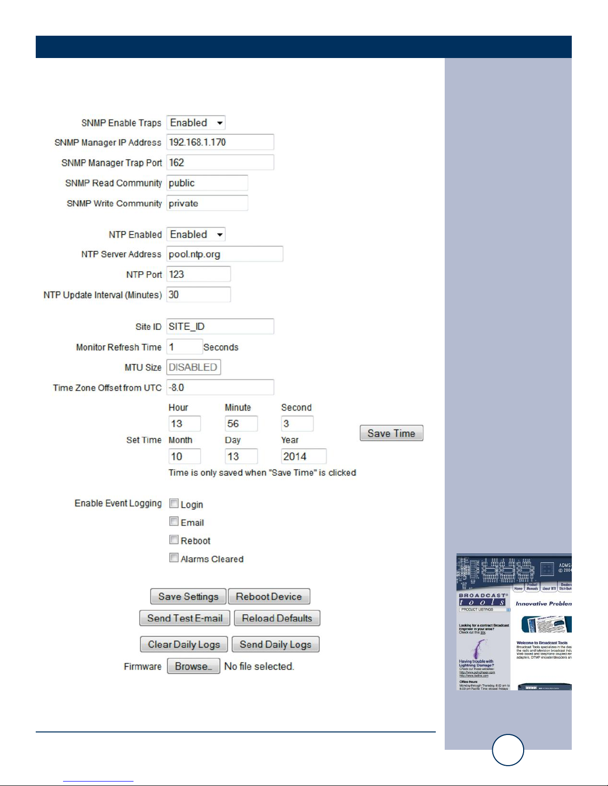
“Email/Network Setup” Web Page – SNMP Manager Settings
SNMP Enable Traps: When enabled trap messages will be sent. When
unchecked, no trap messages will be sent.
SNMP Manager IP Address: This is the IP address of the SNMP manager. The system
will send traps to this IP address only.
SNMP Manager Trap Port: This is the port number that SNMP trap messages will be
sent. Default port 162.
SNMP Read Community: This is the community name for Read-Only access.
SNMP Write Community: This is the community name for Read-Write access.
NOTE: A cold-start trap will be sent when the unit boots up if the SNMP Enable Traps
is checked, otherwise trap messages are sent when a device enters or exits an alarm
condition, depending on whether or not alarms are enabled.
“Email/Network Setup” Web Page – NTP Settings
NTP Enabled: Must be enabled to sync. Default: Enabled
NTP (Time) Server Address: Enter the NTP address here. Default: pool.ntp.org
NTP Port: Normally 123. Default: 123
NTP Update Interval (Min): Interval between timing updates. Default: 30
“Email/Network Setup” Web Page – Other Settings
Site ID: This is the Site Identifier that is display on the web and in
each email.
Monitor Refresh Time (Sec): Interval at which the Monitor & Control page refreshes.
Default: 1 sec.
Time Zone Offset from UTC: Sets the time zone offset from GMT.
Default: -8 hours
Set Time: The hour, minute, second, month, day and year boxes can
be used to set the time of the RTC. The time is only updated if you click “Save Time” and not when you “Save
Settings”.
Enable Event Logging: Enabling these checkboxes will generate an alarm, but will
not send an email. If the system is configured for Daily
Alarm emails, then that Daily Alarm email will contain the
Event Logging items as well.
Login: Whenever someone logs into the system, the username and
date/time will be logged.
Email: Whenever an email is sent, the type of email and date/time
will be logged.
Reboot: Whenever the device boots, the date/time will be logged.
WEBSITE:
Visit our web site for
product updates and
additional information.
Page 24

24
Audio Sentinel®+ Streaming Installation and Operation Manual
SETUP
Alarms Cleared: Whenever the Daily Logs or Normal Alarms are
cleared, the type of log cleared and date/time will be
stored. When Daily Logs are sent, the Daily Logs are
also cleared; this will cause an event log as well.
Save Settings: After pressing the “Save Settings” button, the device
will reboot (If you changed the IP address, you must
navigate your web browser to the new IP address (if
the HTTP port was changed from port 80, be sure to
add the new port number after the IP:
xxx.xxx.xxx.xxx:port #). If you didn’t change the IP
address, then the web page will return to the login
screen after the device reboots.
Reboot Device: When you press the “Reboot Device” button, the
device will restart.
Send Test Email: Press this button to send a test email to Recipient
address #1. The status of the test email will be displayed below. If an email was not sent correctly,
please review your SMTP and network settings and
correct as necessary.
NOTE: After you are done making changes to the Email/Network Setup page,
you MUST press the “Save Settings” button to save your changes.
Reload Defaults: When you press the “Reload Defaults” button, the
device resets to its default settings. After resetting you
must navigate your web browser to the new IP
address: 192.168.1.55
Clear Daily Logs: When you press the “Clear Daily Logs” button, the
daily logs stored in memory will be cleared. Keep in
mind that if the Alarms Cleared Event is enabled, this
event will post after the logs are cleared.
Send Daily Logs: When you press the “Send Daily Logs” button, the
system will send the daily logs email and clear the log
queue.
Firmware: Click the browse button to select a firmware update
file to apply to the Audio Sentinel + Streaming.
CAUTION!
Never load firmware
updates unless instructed to do so by broadcast
tools®. doing so deletes
all software and voids
all warranties from
broadcast tools®, inc.
WEBSITE:
Visit our web site for
product updates and
additional information.
Page 25
25
Audio Sentinel®+ Streaming Installation and Operation Manual
SETUP
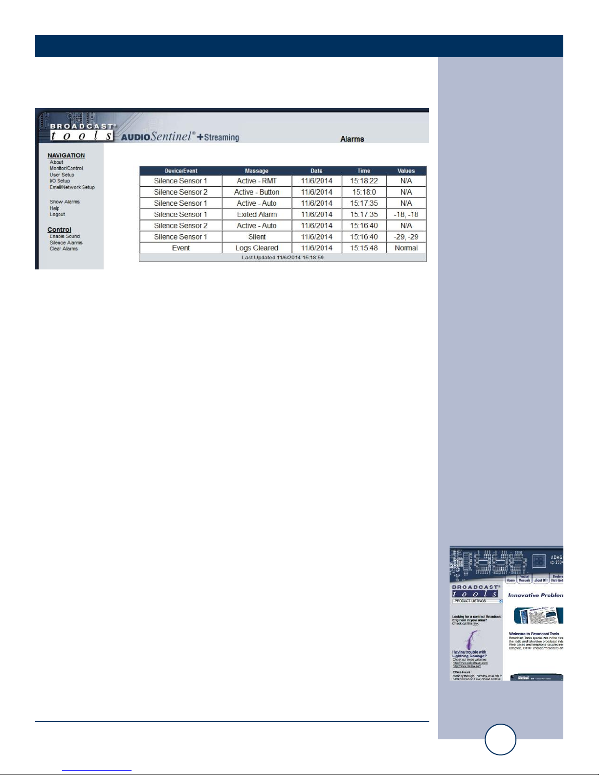
“Show Alarms” Web Page
This page displays current alarms.
Device/Event: Displays which device and/or devices triggered the alarm.
Message: Displays the type of alarm/event.
Date: Displays what date the event was logged.
Time: Displays what time the event was logged.
Values: Displays the parameter recorded.
NOTE: With the “admin” access level, the user may control all functions.
With the “Monitor/Control” or “Monitor” only access level, the user may view the
“Show Log”, enable/disable PC speaker sound and silence alarms.
NOTE: Adobe “Flash” must be installed and operating properly on your PC
for the “Alarm Sound” to work when enabled.
WEBSITE:
Visit our web site for
product updates and
additional information.
Page 26
26
Audio Sentinel®+ Streaming Installation and Operation Manual
SETUP
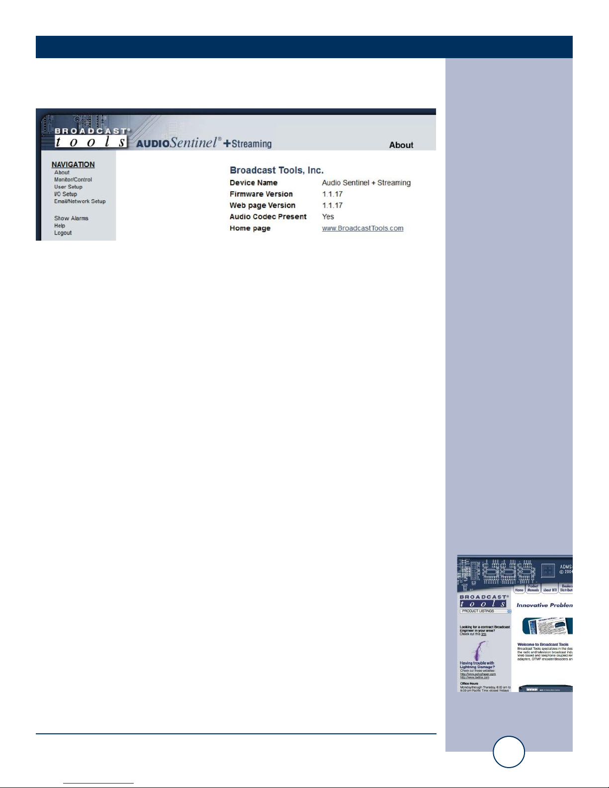
“About” Web Page
The “About” Web Page displays the product name, firmware version numbers,
Audio Codec status (required for streaming functionality), and Broadcast Tools®
Web site link.
WEBSITE:
Visit our web site for
product updates and
additional information.
Page 27

27
Audio Sentinel®+ Streaming Installation and Operation Manual
SPECIFICATIONS
SPECIFICATIONS
Ethernet Interface: RJ-45, 10base-T or 100base-TX, auto sensing with link &
activity led indicators - Full/half duplex.
Input Level: -14 to +24 dBu, 22 K ohm, balanced.
Program switcher: Inputs may be balanced or unbalanced. Output levels,
impedance, distortion, noise and balancing will match that
of the selected input.
Silence Sense (1 & 2) Level: -15 to -35 dB below normal level, in 1dB steps.
Select/EXTernal Input: Closure to ground. Internally pulled up to 5 VDC.
(Sustained or momentary depending on mode).
Relays (K1, K2, K3): 3 - SPDT dry contacts, rated 30 VDC @ 1 Amp.
CAUTION! For safety, never connect 120 Vac circuits to the above relays!
Connectors: All I/O, removable euro-block screw terminals. Mating plugs
supplied.
Power supply: Universal switching power supply with domestic AC con-
nector supplied. International connectors optional. +/-15
VDC 400mA output with 3-pin AMP-style latching power
connector.
Size: 5.65” x 7.10” x 1.575” (WDH) Aluminum chassis w/ 4 4-40
mounting holes.
Weight: 2.0 lb.
Options: * RA-1, 1-RU rack shelf. Accommodates 3 units.
WEBSITE:
Visit our web site for
product updates and
additional information.
Page 28

28
Audio Sentinel®+ Streaming Installation and Operation Manual
LIMITED WARRANTY
LIMITED WARRANTY
The term “Buyer” as used in this document refers to and includes both (but only) (a) any person or entity who acquires such an item for
the purpose of resale to others (i.e., a dealer or distributor of an item), and (b) the first person or entity who acquires such an item for
such person’s or entity’s own use.
Broadcast Tools warrants to each Buyer of any item manufactured by Broadcast Tools that the item will be free from defects in materials and workmanship at the time it is shipped by Broadcast Tools if the item is properly installed, used and maintained.
EXCLUSIVE REMEDIES
If Broadcast Tools is notified, in writing, of a failure of any item manufactured by Broadcast Tools to conform to the foregoing Limited
Warranty within one (1) year following the date of the Buyer’s acquisition of the item, and if the item is returned to Broadcast Tools in
accordance with Broadcast Tools’ instructions for confirmation by inspection of the defect (which at Broadcast Tools’ election may
include, without limitation, a requirement that the Buyer first obtain a Return Authorization number from Broadcast Tools, that the Buyer
furnish proof of purchase in the form of an invoice and/or receipt, and that the Buyer prepay all freight charges associated with any return
of the item to Broadcast Tools using such freight service as Broadcast Tools reasonably may specify), Broadcast Tools will repair or
replace the defective item, or will refund the purchase price paid by the Buyer for the item. Broadcast Tools shall have the exclusive
right to choose between these alternative remedies.
NO OTHER WARRANTIES OR REMEDIES
TO THE MAXIMUM EXTENT PERMITTED BY APPLICABLE LAW, BROADCAST TOOLS AND ITS SUPPLIERS DISCLAIM ALL OTHER
WARRANTIES, EITHER EXPRESS OR IMPLIED, INCLUDING BUT NOT LIMITED TO IMPLIED WARRANTIES OF MERCHANTABILITY OR FITNESS FOR A PARTICULAR PURPOSE; AND THE FOREGOING ALTERNATIVE REMEDIES SHALL BE EXCLUSIVE OF
ALL OTHER REMEDIES. THIS LIMITED WARRANTY GIVES YOU SPECIFIC LEGAL RIGHTS. YOU MAY HAVE OTHER RIGHTS,
WHICH VARY FROM STATE/JURISDICTION TO STATE/JURISDICTION.
NO LIABILITY FOR CONSEQUENTIAL DAMAGES
TO THE MAXIMUM EXTENT PERMITTED BY APPLICABLE LAW, NEITHER BROADCAST TOOLS NOR ANY OF ITS SUPPLIERS
SHALL HAVE ANY LIABILITY FOR ANY SPECIAL, INCIDENTAL, INDIRECT, CONSEQUENTIAL OR PUNITIVE DAMAGES WHATSOEVER (INCLUDING, WITHOUT LIMITATION, ANY DAMAGES FOR LOST PROFITS, BUSINESS INTERRUPTION, LOSS OF DATA OR
INFORMATION, COST OF CAPITAL, CLAIMS OF CUSTOMERS, OR ANY OTHER PECUNIARY LOSS) ARISING OUT OF THE USE
OF OR THE INABILITY TO USE ANY ITEM SUPPLIED BY BROADCAST TOOLS, EVEN IF BROADCAST TOOLS HAS BEEN
ADVISED OF THE POSSIBILITY OF SUCH DAMAGES HAVE ANY LIABILITY FOR ANY SPECIAL, INCIDENTAL, CONSEQUENTIAL,
EXEMPLARY OR PUNITIVE DAMAGES. THIS LIMITATION OF LIABILITY APPLIES WHETHER A CLAIM IS ONE ALLEGING
BREACH OF A CONTRACT OR WARRANTY, NEGLIGENCE OR OTHER TORT, FOR THE VIOLATION OF ANY STATUTORY DUTY,
THE FAILURE OF ANY LIMITED OR EXCLUSIVE REMEDY TO ACHIEVE ITS ESSENTIAL PURPOSE, OR ANY OTHER CLAIM OF
ANY NATURE. BECAUSE SOME STATES AND JURISDICTIONS DO NOT ALLOW THE EXCLUSION OR LIMITATION OF LIABILITY
FOR INCIDENTAL OR CONSEQUENTIAL DAMAGES, THIS LIMITATION MAY NOT APPLY TO YOU.
Broadcast Tools, Inc.
131 State Street
Sedro-Woolley, WA 98284 • USA
360.854.9559
voice • 866.783.1742 fax
[email protected] e-mail
www.broadcasttools.com website
Page 29
Audio Sentinel®+ Streaming Installation and Operation Manual
29
APPENDIX
Page 30
Audio Sentinel®+ Streaming Installation and Operation Manual
30
APPENDIX
Page 31
Audio Sentinel®+ Streaming Installation and Operation Manual
31
APPENDIX
Page 32
Audio Sentinel®+ Streaming Installation and Operation Manual
32
APPENDIX
Page 33
Audio Sentinel®+ Streaming Installation and Operation Manual
33
APPENDIX
 Loading...