

Broadcast Pix Slate 1000, Slate HD 100, Slate 2100, Slate3000, Slate HD 100h Operator's Manual
...Page 1
Slate 100 / 1000 / 2100 / 3000
1 ME HD & SD Video Switchers
Operators Manual
Software Version 7.0
Broadcast Pix V7.0
install - concepts - PixMaster - switcher - CG - clips - controls - team - appendix
Page 2

Warranty on all Slate Switchers
The Products will be of a professional quality, meet the specifications set forth in the
Product descriptions and are warranted to be free from defects in materials and
workmanship for a period of one (1) year from delivery. Broadcast Pix will repair or, at
its sole option, replace any component found to be faulty on any system returned to the
service center of Broadcast Pix in the USA for repair. The costs of any visit to the
customer's site are not included in the warranty. The cost of returning Product to
Broadcast Pix is the responsibility of the end user or the Dealer. Dealer is authorized to
deliver the Broadcast Pix warranty, as described above, to purchasers of the Products
and the Future Products. No software is to be added to the product from any other
source than Broadcast Pix, unless approved by Broadcast Pix, or it will invalidate this
warranty.
BROADCAST PIX MAKES NO OTHER WARRANTY, EXPRESSED OR IMPLIED, AND
PARTICULARLY EXCLUDES ANY IMPLIED WARRANTIES OF MERCHANTABILITY
OR FITNESS FOR A PARTICULAR PURPOSE.
Made in the United States of America
© 2008 Copyright Broadcast Pix, Inc. July 2008
Broadcast Pix, Slate, iBoB, PixButtons, PixMaster, PixPad, AutoAspect, and SoftPanel are trademarks of Broadcast Pix, Inc.
Other trademarks are owned by their respective companies.
Broadcast Pix V7.0
install - concepts - PixMaster - switcher - CG - clips - controls - team - appendix
0.1
Page 3

Table of Contents
Section 1 Installation and Getting Started
1.1 Video I/O Configurations
1.1.1 Analog Video I/O
1.1.2 HD I/O
1.1.3 Optional DVI-I I/O
1.2 Broadcast Pix Slate 100
1.2.1 System Contents
1.2.2 Wiring Diagram
1.3 Broadcast Pix Slate 1000
1.3.1 System Contents
1.3.2 Wiring Diagram
1.3.3 Optional Tally Box Wiring
1.3.4 Installing Tally Box Drivers
1.4 Audio I/O
1.5 Slate I/O Assignments
1.5.1 AutoAspect for Inputs
1.6 Broadcast Pix Slate 2100
1.6.1 System Contents
1.6.2 Wiring Diagram
1.6.3 iBoB Audio I/O Wiring
1.6.4 iBoB Tally Wiring
1.6.5 iBoB Assignments
1.6.6 Setting up the iBoB from the Control Panel
1.7 Broadcast Pix Slate 3000
1.7.1 System Contents
1.7.2 Slate 3016dd & 3016hh Wiring Diagram
1.7.3 Slate 3032dd & 3032hh Wiring Diagram
1.7.4 Multiple Slate Systems
1.7.5 Example Slate 3032 & Slate 1000 Wiring
1.7.6 Optional Tally Box Wiring
1.7.7 Optional Remote Aux Panel Wiring
1.7.8 Router Assignments
1.7.9 Router Assignments for a Dual System Configuration (contact technical support)
Broadcast Pix V7.0
install - concepts - PixMaster - switcher - CG - clips - controls - team - appendix
0.1
Page 4

Table of Contents
Section 1 Installation and Getting Started
1.8 Running a Show
1.9 The Sample Show
1.9.1 Internal Content for Sample Show NTSC
1.9.2 Testing the System
1.9.3 The Sample Show Memories
1.10 Troubleshooting
1.11 Input Timing & Asynchronous Sources
1.11.1 System Delay
1.12 Changing what show is running
1.13 Settings
1.13.1 Changing the Startup Show
1.13.2 Selecting between NTSC/525 and PAL/625
1.13.3 Selecting between Aspect Ratio 16:9 and 4:3
1.14 DualAspect
1.15 Control Panel Installation
Broadcast Pix V7.0
install - concepts - PixMaster - switcher - CG - clips - controls - team - appendix
0.1
Page 5

Table of Contents
Section 2 Broadcast Pix Concepts
2.1 Broadcast Pix Switcher Features
2.1.1 Video Flow Diagram
2.2 PixButtons for Executing with Confidence
2.3 Devices
2.4 Device Controls
2.4.1 Assigning the Device Controls
2.4.2 PixPad Navigation
2.4.3 Multi-View PixPad
2.4.4 PixPad Order Controls
2.4.5 Floating PixPads
2.5 Multi-View
2.5.1 Monitor Sizes
2.5.2 Overview of the Multi-View
2.5.3 Sources on Multi-View
2.5.4 Keyer on the Multi-View
2.5.5 Clip Store Counters
2.5.6 Basic Switching on the Multi-View
2.5.7 Advanced Switching on the Multi-View
2.5.8 About Tab
2.5.9 Floating Monitors
2.5.10 Clocks on the Multi-View
2.6 List of Screen Resolutions
2.6.1 Adjusting the Windows Desktop Screen Resolution
2.6.2 Optional Quad Monitor Card
2.7 Keyboard Shortcuts
2.7.1 Enabling Keyboard Shortcuts
2.7.2 Using Keyboard Shortcuts
Broadcast Pix V7.0
install - concepts - PixMaster - switcher - CG - clips - controls - team - appendix
0.2
Page 6

Table of Contents
Section 3 PixMaster Show Editor
3.0 PixMaster Storage System
3.1 Creating a New Show
3.2 Selecting an Existing Show to Edit
3.3 Editing a Show
3.4 Editing a Show’s Content
3.5 Reordering, Adding or Removing Content
3.5.1 To Reorder Content
3.5.2 To Reorder a Group of Content
3.5.3 Adding content from the central Library
3.5.4 Adding a group of content from the central library
3.5.5 Importing Content
3.5.6 Importing a Content into a Subfolder
3.5.7 Resize and soften images
3.5.8 Importing PowerPoint Slides into a Still Store
3.5.9 Previewing Content
3.5.10 Renaming Content
3.5.11 Removing Content from a Show
3.5.12 Permanently Deleting Content from the Library
3.6 Show Content Summary
3.7 Editing Show Settings
3.7.1 Switcher Source Assignments
3.7.2 Auto Fail-Safe Setting
3.7.3 Adding Wildcard Devices
3.7.4 Show Memories
3.7.5 Global Naming of Memories
3.7.6 Custom Images on Memory PixButtons
Broadcast Pix V7.0
install - concepts - PixMaster - switcher - CG - clips - controls - team - appendix
0.3
Page 7

Table of Contents
Section 4 Production Switcher
4.0 Switcher Controls
4.0.1 Tally
4.1 Video Sources
4.1.1 Program Row Source Selection.
4.1.2 Accessing Inputs 9-18 with Shift
4.2 Transitions
4.2.1 Transition Preview
4.2.2 Background Cut Transition
4.2.3 Background Mix Transition
4.2.4 Background Effects Transition
4.3 Transition Effects
4.3.1 Effects Styles and PixButtons
4.3.2 Selecting a New Effect by Number
4.3.3 Viewing More Effects in the Library
4.3.4 Changing Effect Transition Rates
4.3.5 Modifying an Effect
4.4 Keys
4.4.1 Key Controls
4.4.2 Assigning a Source to Keys 1-3
4.4.3 Direct Keys Control
4.4.4 Transitioning Keys individually with PixButtons
4.4.5 Transitioning Keys with other keys or with the Background
4.4.6 Modifiers for Keyers
4.4.7 To Change the Key Fade Rate
4.5 DVE Boxes (Picture in Picture)
4.5.1 To Create a DVE Box:
4.5.2 Modifying a DVE Box
4.5.3 Dual and Triple DVE Boxes
4.5.4 Accessing Keys 4-6
4.6 Source Controls
4.7 Chromakey
4.7.1 Activating the Chromakey
4.7.2 Settings for the Chromakey
4.7.3 Adjusting the Chromakey
Broadcast Pix V7.0
install - concepts - PixMaster - switcher - CG - clips - controls - team - appendix
0.4
Page 8

Table of Contents
Section 4 Production Switcher
4.8 External Key
4.8.1 To Setup External Key
4.8.2 To Operate External Key
4.8.3 iBoB DSK Downstream on Slate 2100
4.8.4 To Enable/Disable iBoB DSK
4.8.5 To Turn On & Set Up iBoB DSK
4.8.6 To Operate & Modify iBoB DSK
4.9 Auxiliary Output Control
4.9.1 Aux Out on Slate 100 & 1000
4.9.2 Aux Out on Slate 2100
4.9.3 Aux Out on Slate 3016
4.9.4 Aux Out on Slate 3032
4.9.5 Assigning Output Sources
4.9.6 Remote Aux Panel on Slate 3016/3032
4.9.7 Programming the Remote Aux Panel
4.9.8 PowerAux Control
4.10 StudioMemory
4.10.1 Saving a Mem
4.10.2 Recalling a Mem
4.11 Scripts
4.11.1 To Record a Script
4.11.2 Playing a Script
4.11.3 ScriptsManager Setup
4.11.4 Alpha Wipes
4.12 Fail-Safe On-Air Production
4.12.1 Fail-Safe on Slate 100 and Slate 1000
4.12.2 Fail-Safe on Slate 2100 & 3000
4.12.3 Fail-Safe Operation on Slate 2100
4.12.4 Fail-Safe Operation on Slate 3000
4.13 Capture of Stills
4.13.1 Capturing an Image
4.13.2 Capture Folder Destination
Broadcast Pix V7.0
install - concepts - PixMaster - switcher - CG - clips - controls - team - appendix
0.4
Page 9

Table of Contents
Section 5 CG and Graphics
5.1 CG Installation
5.1.1 TitleMotion Pro Canvas
5.2 Creating Still CG Graphics
5.2.1 Exporting a Still Graphic from Inscriber to Broadcast Pix
5.2.2 Exporting Graphics from Photoshop to Broadcast Pix
5.3 CG Rolls and Crawls
5.3.1 To Create CG Graphics that Roll or Crawl
5.3.2 To Play a Roll or Crawl
5.3.3 Motion Controls for Rolls and Crawls
5.3.4 Modifiers for Rolls and Crawls
5.4 Creating an Animated CG Graphic
5.4.1 To Create an Animated Graphic
5.4.2 Importing an Animated CG Graphic into Broadcast Pix
5.4.3 On-Air Operations for CG Animations
5.4.4 Creating Animations in 3rd Party Applications
5.5 Basic CG On-Air Operation
5.6 Updating CG Graphics On-the-Fly
5.6.1 .ICG Editing
5.6.2 Overwriting a File
5.7 Dual CG
5.8 Still Store and Logo Operation
5.8.1 Preparing Still Content
5.9 Optional CG Connect Software
5.9.1 Adding the RTX Tags
5.9.2 Loading CG Connect with a Layout
5.9.3 Updating the CG Layout
5.9.4 Adding a Data Source with XML Files
5.9.5 Creating your Own XML File
5.9.6 Using Images with CG Connect
5.9.7 Using Clocks with CG Connect
5.9.8 Displaying the CG Layout
5.10 Using International Characters with Inscriber
Broadcast Pix V7.0
install - concepts - PixMaster - switcher - CG - clips - controls - team - appendix
0.5
Page 10

Table of Contents
Section 6 Clip Store
6.0.1 Audio Flow with Embedded Audio
6.0.2 Audio Flow with Digital AES/EBU Audio
6.0.3 Audio Flow with Analog Stereo Audio
6.1 Recording a Clip
6.1.1 Creating Clip Thumbnails
6.2 Clip Store Playout
6.3 To Select a Clip by Name
6.3.1 To Select a Clip by Number
6.3.2 Selecting a Clip with the Multi-View
6.3.3 Viewing More Clips in the Library
6.3.4 Playback of Compressed Clips
6.3.5 Exporting Compressed Clips from Final Cut Pro
6.4 Clip Motion Controls
6.4.1 Clip Counter
6.5 Clip Modifiers
6.5.1 Mark In and Out Points
6.5.2 Auto Start Clips
6.5.3 Auto Stop Clips
6.5.4 Auto Rewind Clips
6.5.5 Loop Clips
6.5.6 AutoAspect Controls
6.5.7 Scrubbing a Clip
6.6 Setting the Clip Audio Advance
6.7 Optional Dual Clip Store
6.8 Optional External DDR Control
6.8.1 Installing External DDR Control
6.8.2 Verifying Installation of External DDR Control
6.8.3 Selecting Clips to Access
6.8.4 Adding DDR Control to a Show
6.8.5 Controlling External DDR
6.8.6 Looping
6.8.7 Accessing More Channels
Broadcast Pix V7.0
install - concepts - PixMaster - switcher - CG - clips - controls - team - appendix
0.6
Page 11

Table of Contents
Section 7 Device Control Options
7.1 Camera Control Option
7.1.1 Camera Control Option Licensing
7.2 Installation of Sony Cameras
7.2.1 Wiring Configurations
7.3 Installation of Hitachi Cameras
7.3.1 One Camera Installation
7.3.2 Multi-Camera Installation
7.4 Adding Camera Control to an Existing System
7.4.1 Setting the COM Port
7.5 Camera Control Settings
7.5.1 Sony Camera Control Settings
7.5.2 Hitachi Camera Control Settings
7.5.3 Assigning the Camera Number
7.6 Adding Camera Control to a Show
7.7 Selecting Camera Control in a Production
7.8 Controlling a Camera Manually
7.9 Setting Camera Preset Positions
7.9.1 Recalling Preset Camera Positions
7.9.2 Recall Speed for Preset Positions
7.10 Hitachi Camera Control Settings
7.10.1 Travel Limits of Tilt and Pan
7.10.2 Adjusting CCU Functions
7.11 Sony Camera Control Settings
7.11.1 Adjusting CCU Functions
7.12 Optional Audio-Follow-Video Control
7.12.1 Enabling Audio Follow
7.12.2 Activating Audio Follow
7.12.3 Audio Follow Setup
7.12.4 Audio Follow Operation
Broadcast Pix V7.0
install - concepts - PixMaster - switcher - CG - clips - controls - team - appendix
0.7
Page 12

Table of Contents
Section 8 Team Operation
8.1 Types of Multi-User Operation
8.2 Optional Multi-Panel Support
8.3 Adding a Separate Graphics Operator
8.3.1 Two Operators with Separate Graphics Operator and 1 Panel
8.3.2 Two Operators with Separate Graphics Operator and 2 Panels
8.4 Locking Panels Together
8.5 Viewing just a portion of the SoftPanel
8.6 Two Operators with Two Computers
8.7 Remote Operator in the Back Room
8.8 Dual Panels for Back-Up Redundancy
8.9 Remote Control
Appendix
A.1 Updating the Software to Future Versions
A.2 Updating the Control Panel or iBoB Firmware
A.3 Installing System Options
A.4 Classic Show Editor
A.5 Control Panel Internal Operation
A.6 Broadcast Pix Slate Analog Video Connector Pin-Outs
A.7 Broadcast Pix Slate Analog Audio Breakout Cable
A.8 RS-232 Serial Pin-Out for Slate 2100 & Slate 3000 Fail-Safe Control
A.9 Custom Shortcuts Keyboard Layout
A.10 Broadcast Pix Slate Technical Specifications
A.11 Glossary
A.12 Broadcast Pix Contact Information
Broadcast Pix V7.0
install - concepts - PixMaster - switcher - CG - clips - controls - team - appendix
0.8
Page 13

Section 1:
Installation and Getting Started
Thank you for purchasing a Broadcast Pix Slate video switcher, soon you will be
experiencing how we have redefined the switcher.
There are a total of 25 Slate switcher models, as shown below, all of which use the
same BPSwitcher software, each with unique hardware to control the software.
Take note to which model you have purchased and refer to that section in this
manual prior to installing your Broadcast Pix Switcher.
Slate Configurations:
There are 9 Slate 100 configurations:
Slate HD Slate SD
100h 100a
100hh 100d
100ha 100aa
100hd 100dd
100da
There are 9 Slate 1000 configurations:
Slate HD Slate SD
1000h 1000a
1000hh 1000d
1000ha 1000aa
1000hd 1000dd
1000da
There are 3 Slate 2100 configurations:
Slate HD Slate SD
2100dh 2100da
2100dd
There are 4 Slate 3000 configurations:
Slate HD Slate SD
3016hh 3016dd
3032hh 3032dd
Broadcast Pix V7.0
install - concepts - PixMaster - switcher - CG - clips - controls - team - appendix
1.0
Page 14

1.1 Video I/O Configurations
All Slate switchers have a switcher output board on the right, which does the
processing and contains video outputs and an analog reference input. There are 2
slots for Input/Output boards, of which the center is standard and the left board is
optional. Either I/O board may be Serial Digital Interface (SDI), Analog or High
Definition-SDI (HD/SD-SDI). SD-SDI and HD-SDI connections are BNCs. Analog
connections accept S-Video (Y/C) connections or Composite and Component (YUV/
YPrPb) using the supplied breakout cables to BNCs. Sources can be synchronous
and /or asynchronous, to support a wide range of inputs from broadcast cameras to
consumer DVD players.
3 Standard Configurations
a (analog) d (SD digital) h (high-def & SD digital)
Optional Second I/O Board
aa dd da
NOTE: It is not recommended to have long cable runs over 200 meters (655 feet) for SD and 100 meters
(325 feet) for HD, as signal quality will be degraded. For longer runs, it is necessary to install video
amplifiers/reclockers to boost the signal, although external components may increase overall system
delay.
Broadcast Pix V7.0
install - concepts - PixMaster - switcher - CG - clips - controls - team - appendix
1.1
Page 15

1.1 Video I/O Configurations Continued
Second I/O Board using HD & Optional DVI I/O Board
The DVI I/O board is an optional I/O card that is can be added to any HD Slate system.
The DVI card is installed next to the Multi-View monitor card and always has 2 DMS-59
connectors. The DVI input uses input 4 on the HD card in slot #2, and input 8 on slot #3.
Output D is in place of Out D on slot #2, and output E is in place of Out E on slot #3.
ha hd
Multi
View
House
Network
Analog
I/O
HD
I/O
Slate
Out
DVI
I/O
Multi
View
House
Network
Digital
I/O
HD
I/O
Slate
Out
DVI
I/O
hh
DVI
Multi
House
I/O
View
Network
NOTE: On HD I/O cards with the optional DVI I/O card, output D/E can not output both a HD-SDI and a
DVI/VGA signal at the same time, either one or the other as selected in the Slate I/O Assignments
window.
HD
I/O
HD
I/O
Slate
Out
Broadcast Pix V7.0
install - concepts - PixMaster - switcher - CG - clips - controls - team - appendix
1.1
Page 16

1.1.1 Analog Video I/O
The Analog video I/O connectors on the Slate board set are 7-pin Geo-Port
connectors which can accept S-Video cables directly, and Composite and Component
signals via BNC breakout cables provided by Broadcast Pix. Composite cables are
included with all Slate switcher models for each analog input and output. Three
component/composite break out cables are included with the Slate 100 and Slate
1000 models, and one component cable with the Slate 2100 and Slate 3000 models.
Additional component cables are available as an option. The green connector on a
component break out cable can also accept a composite video signal.
Composite
Cable
Component
Cable
NOTE: For technical specifications of the pin-out of the analog video I/O connector, see Appendix A.6.
Broadcast Pix V7.0
install - concepts - PixMaster - switcher - CG - clips - controls - team - appendix
1.1.1
Page 17
1.1.2 HD I/O
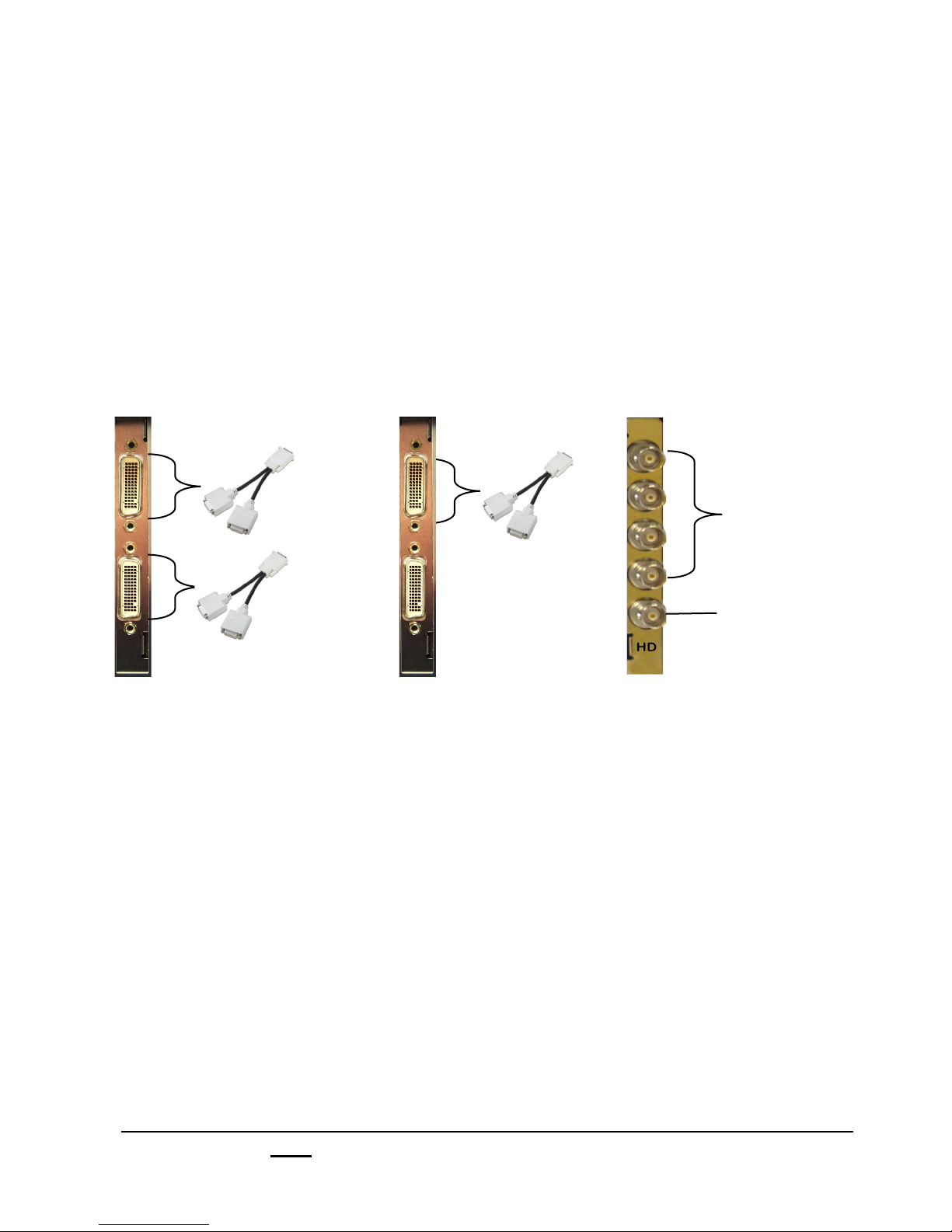
The High Definition I/O connectors on the Slate board set are BNC connectors. All inputs
and outputs can either be HD-SDI or SD-SDI for standard definition. The bottom
connector is a HD output and the remaining 4 connections are HD inputs. The Slate
system supports high definition video in:
1080i/60/59.94, 720p/60/59.94, 1080i/50, 720p/50, 487i/59.94 and 576i/50 modes and
supports the standards:
SMPTE 296M, SMPTE 274M, ITU-R BT601-5, SMPTE 259M and SMPTE 292M.
The Slate HD boards down-convert the signal coming in and then up converts the signal
going out. The system can also down-convert going out for standard definition on any of
the other Slate outputs while outputting a HD signal on the HD output card.
Input 4 &
Output D
4 HD/SD SDI
Inputs
Input 8 &
Output E
Input 4 or 8
&
Output D or E
1 HD/SD SDI
Output
Bottom connector
not used.
hh system h system h system
1.1.3 Optional DVI-I I/O
The Slate video switcher is primarily used for broadcast television applications, although
the system can be used in virtually any production scenario. Every Slate switcher can
optionally support up to two DVI-I computer inputs and up to two DVI-I outputs (VGA
adaptors are included to convert the signal) through dual DMS-59 connectors. This is
ideal for corporate, faith or event productions where a computer source is needed, for
example to run a PowerPoint slideshow. Although it is possible to use a S-Video input or
a scan converter to bring in computer signals with SD configurations, the DVI-I option
gives the highest quality computer signal. Each DMS connector has an input and output
as labeled on the breakout cable. The DVI input can support resolutions VGA (640x480)
to DVI WUXGA (1920x1200), as well as HD Analog YPrPb through the optional DVI to
component cable. The DVI output can support resolutions VGA (640x480) to DVI
WUXGA (1920x1200), as well as HD 1080p through the optional DVI to HDMI cable.
The DVI-I card is optional on only HD Slate systems and uses inputs 4 and/or 8 and
outputs D and/or E from the HD card, selectable in the Slate I/O Assignments window. If
two DVI ports are needed, then two HD I/O cards are necessary. You can not output
through the DVI card and the HD card simultaneously.
Broadcast Pix V7.0
install - concepts - PixMaster - switcher - CG - clips - controls - team - appendix
1.1.2
Page 18

1.2 Broadcast Pix Slate 100
This section covers the typical installation of a Broadcast Pix Slate system and some
options. Other options that require installation are covered in their sections.
1.2.1 Slate 100 System Contents
The Broadcast Pix Slate 100 is comprised of the following components:
Broadcast Pix Software,
Showing the Multi-View
(VGA monitor
not included )
Broadcast Pix
SoftPanel
Software:
BPSwitcher V7
Inscriber TitleMotion Pro
Character Generator
Microsoft Windows XP
Workstation with Slate boards
installed
Broadcast Pix V7.0
install - concepts - PixMaster - switcher - CG - clips - controls - team - appendix
Custom shortcut keyboard and mouse
1.2
Page 19

Broadcast Pix Slate 100 System Includes:
Hardware
Workstation, with Slate board and I/O board
25-Pin to 6-XLR Audio Breakout cable (for analog audio I/O)
Inscriber USB Dongle, installed internally in the workstation at the factory
USB Custom keyboard, for using shortcuts
USB Mouse
Software
Broadcast Pix Software V7
Inscriber TitleMotion Pro Character Generator
Microsoft Windows XP Service Pack 2 and .NET 1.1 & 2.0
Requirements
To install a system you will also need:
At least one VGA monitor (at least 1280x1024 resolution)
Sync Generator or other source of house black burst (analog reference)
NOTE: You may not use a PS2 mouse while using the custom keyboard, as the mouse will not function.
Broadcast Pix V7.0
install - concepts - PixMaster - switcher - CG - clips - controls - team - appendix
1.2.1
Page 20
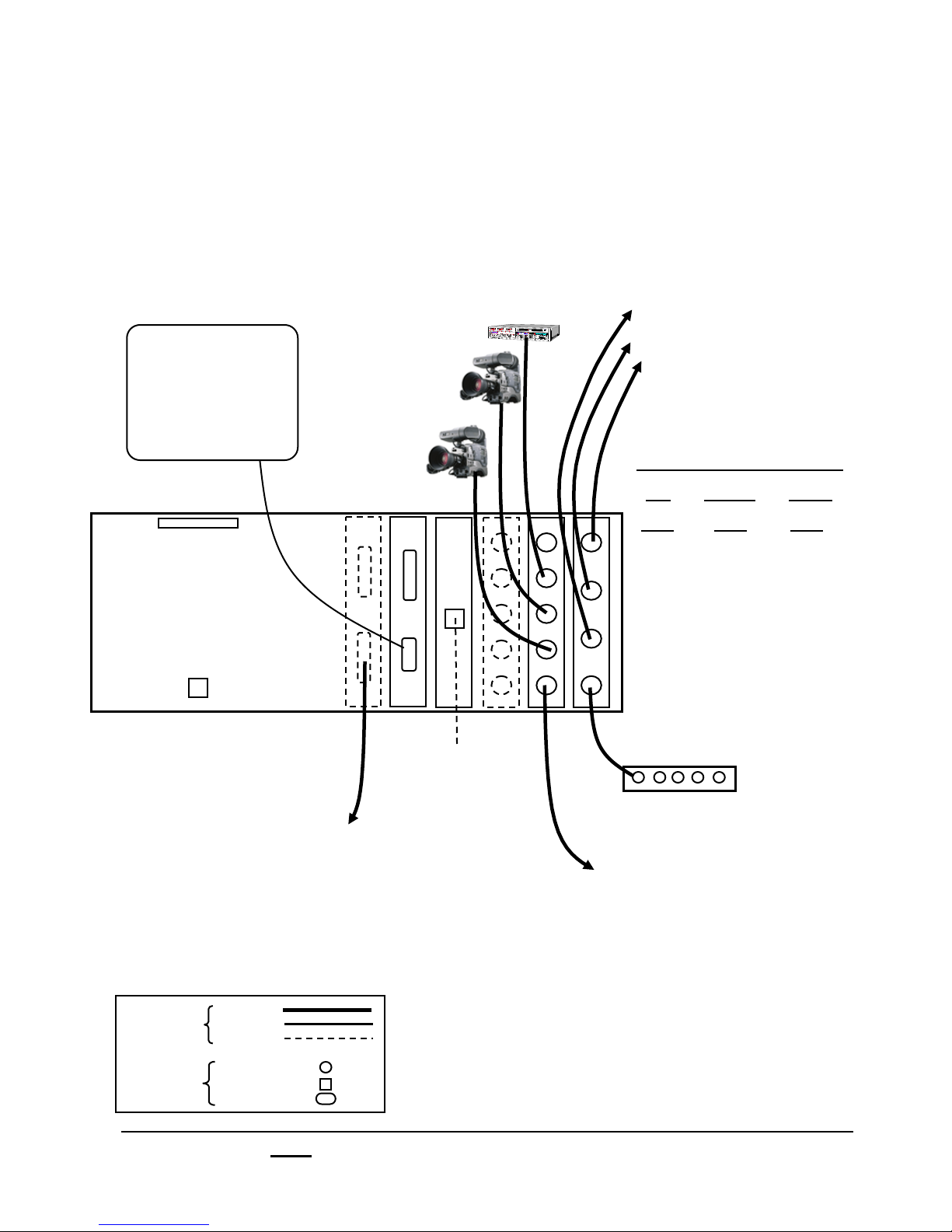
1.2.2 Wiring Diagram for Slate 100
The Slate 100 and Slate 1000 are identical systems except
the 1000 has a physical control panel connected, while the
100 uses the custom keyboard and a SoftPanel. The
keyboard can be enabled by pressing Shift and Panel On/
Off on the keyboard. The SoftPanel can be reached from the
Panel drop down menu, then SoftPanel, Flash Player
in BPswitcher.
VGA
Monitor(s)
Video Outputs
(assignable under the
Slate I/O Assignments)
•! Program
•! Preview
•! Clean Feed
•! Auxiliary (Aux) Out 1
Slate Board Set
(left I/O board is optional)
25-Pin Dim
for analog I/O cable
NIC 2
10/100MB
DVI/VGA Output
(if HD I/O card is installed)
NOTE: On HD I/O cards, the
output can not output both a HD-
SDI and a DVI/VGA signal at the
same time, either one or the other.
See section 1.5.
Key
Wires
Connectors
Video
VGA
Ethernet
Video
Network
Serial
NIC 1
1GB
Network
for moving
content
left
I/O
In 8
In 7
center
I/O
In 4
In 3
Right
Switcher
Out A
Out B
In 6
In 5
Out E
Sync Generator
In 2
In 1
Out D
Out C
Ref
Fail-Safe Program Output
(outputs input 1 if the workstation
stops or if power fails)
NOTE: On Analog I/O cards, the
format of Input 1/5 must match
the format of Output D/E for
Fail-Safe video to work properly.
Both need be be either
Composite, Y/C or YUV.
Broadcast Pix V7.0
install - concepts - PixMaster - switcher - CG - clips - controls - team - appendix
1.2.2
Page 21

1.3 Broadcast Pix Slate 1000
1.3.1 Slate 1000 System Contents
The Broadcast Pix Slate 1000 is comprised of the following components:
Broadcast Pix Software,
Showing the Multi-View
(VGA monitor
not included )
Broadcast Pix
Control Panel
Software:
BPSwitcher V7
Inscriber TitleMotion Pro
Character Generator
Microsoft Windows XP
Broadcast Pix V7.0
install - concepts - PixMaster - switcher - CG - clips - controls - team - appendix
Broadcast Pix
SoftPanel
Workstation with Slate boards
installed, Keyboard, Mouse
1.3
Page 22

Broadcast Pix Slate 1000 System Includes:
Hardware
Broadcast Pix Control Panel
Workstation, with Slate board and I/O board
Network Crossover Cable (to connect panel to workstation)
25-Pin to 6-XLR Audio Breakout cable (for analog audio I/O)
Inscriber USB Dongle, installed internally in the workstation at the factory
PS2 Keyboard
USB Mouse
Software
Broadcast Pix Software V7
Inscriber TitleMotion Pro Character Generator
Microsoft Windows XP Service Pack 2 and .NET 1.1 & 2.0
Requirements
To install a system you will also need:
At least one VGA monitor (at least 1280x1024 resolution)
Sync Generator or other source of house black burst (analog reference)
Broadcast Pix V7.0
install - concepts - PixMaster - switcher - CG - clips - controls - team - appendix
1.3.1
Page 23
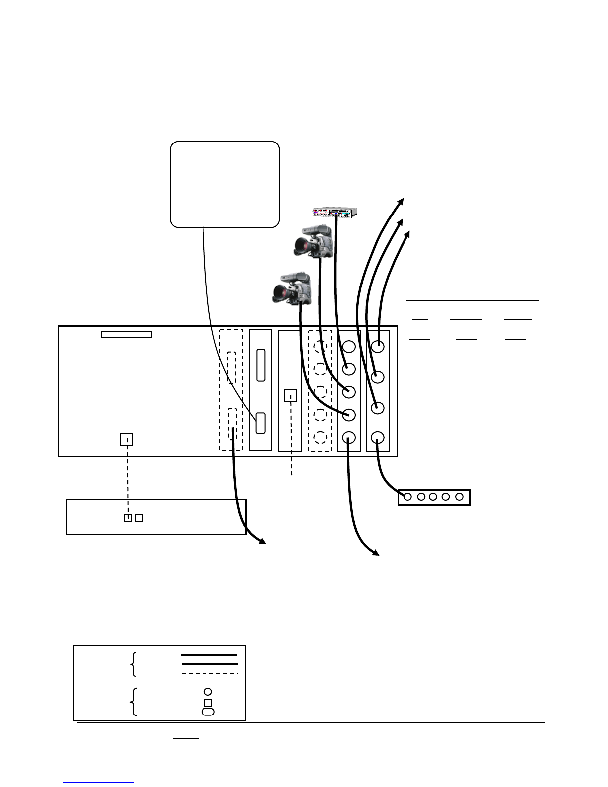
1.3.2 Wiring Diagram for Slate 1000
VGA
Monitor(s)
Video Outputs
(assignable under the
Slate I/O Assignments)
•! Program
•! Preview
•! Clean Feed
•! Auxiliary (Aux) Out 1
Slate Board Set
(left I/O board is optional)
25-Pin Dim
for analog I/O cable
NIC 2
10/100MB
Network
Crossover Cable
Key
Wires
Control Panel
On Slate 1000
Video
VGA
Ethernet
NIC 1
1GB
Network
for moving
content
DVI/VGA Output
(if HD I/O card is installed)
NOTE: On HD I/O cards, the
output can not output both a HDSDI and a DVI/VGA signal at the
same time, either one or the
other.
left
I/O
In 8
In 7
center
I/O
In 4
In 3
Right
Switcher
Out A
Out B
In 6
In 5
Out E
Sync Generator
In 2
In 1
Out D
Out C
Ref
Fail-Safe Program Output
(outputs input 1 if the workstation
stops or if power fails)
NOTE: On Analog I/O cards, the
format of Input 1/5 must match
the format of Output D/E for
Fail-Safe video to work properly.
Both need be be either
Composite, Y/C or YUV.
Connectors
Broadcast Pix V7.0
Video
Network
Serial
install - concepts - PixMaster - switcher - CG - clips - controls - team - appendix
1.3.2
Page 24

1.3.3 Optional Tally Box on the Slate 100 and 1000
The tally box option is a stand-alone Sense & Switch 8 tally and GPIO box that plugs
into the workstation via a USB connection. It provides 8 relays for tally output to your
camera control units and 8 isolated inputs for General Purpose Inputs/Outputs contact
points. All 8 external sources plugged into the Slate I/O cards can be tallied, as shown
by the diagram below.
Input 1 on the Slate card corresponds to ‘0’ on Tally Box
Standard Input 2 on the Slate card corresponds to ‘1’ on Tally Box
I/O Input 3 on the Slate card corresponds to ‘2’ on Tally Box
Input 4 on the Slate card corresponds to ‘3’ on Tally Box
Input 5 on the Slate card corresponds to ‘4’ on Tally Box
Optional Input 6 on the Slate card corresponds to ‘5’ on Tally Box
I/O Input 7 on the Slate card corresponds to ‘6’ on Tally Box
Input 8 on the Slate card corresponds to ‘7’ on Tally Box
Each relay contact is rated at 6 amps at 120 volts AC or 28 volts DC. The convenient
screw terminals can accept cable from 12 to 22 AWG.
NOTE: The ‘Inputs Contacts’ (IP A/B) are for General Purpose Inputs (GPI). The ‘Relay Contacts’ are for
Tally. ‘NO’ for Normally Open, ‘C’ for Common or Ground, ‘NC’ for Normally Closed.
Broadcast Pix V7.0
install - concepts - PixMaster - switcher - CG - clips - controls - team - appendix
1.3.3
Page 25

Installing the Optional Tally Box:
Run a set of wires from each terminal in the Tally Box to each terminal on your camera/
camera unit, one to Program and the other to the Ground, as shown below.
‘NO’ (Normally Open) goes to Program and ‘C” (Common) goes to Ground.
‘NC’ (Normally Closed) is not used.
The Tally box uses one of the computers USB ports, and needs to plugged into an
electrical socket with the supplied power supply.
CAMERA 1
CAMERA 2
CAMERA 3
* Camera Control Unit will vary depending on manufacturer.
2 LEDs should illuminate when power is connected: External Power should be solid
green, Status solid green when connected to the workstation and flashing green when
the workstation is communicating to the tally box.
NOTE: The Tally Box does not supply any voltage for tally. Voltage must be provided by your
Camera Control Units or other source. The Tally Box only opens and closes the tally circuit.
Check your Camera Control Unit’s user manual for more information.
Broadcast Pix V7.0
install - concepts - PixMaster - switcher - CG - clips - controls - team - appendix
1.3.3
Page 26
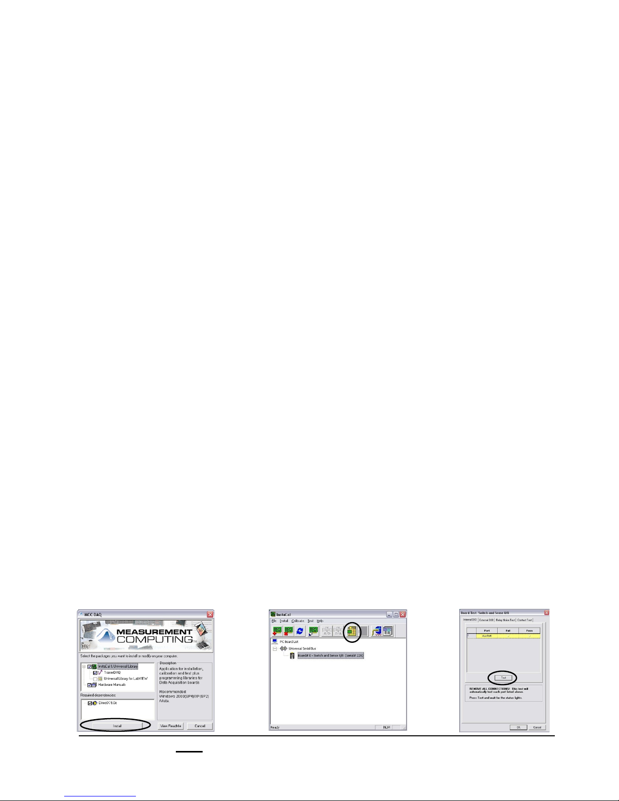
1.3.4 Installing Tally Box Drivers
When the tally box option is purchased with a new unit the appropriate drivers are preinstalled at the factory, there is no need to re-install the drivers. On upgrades, where the
tally box option was purchased after receiving a system, you will need to manually load
the drivers for the Sense & Switch 8 Tally Box, with the install CD that was included with
the tally box. In addition you will need to install an option code, as described in section
A.3, that can be obtained from Technical Support.
To install the drivers:
1.! Insert the Measurement Computers driver disc into the CD tray of the workstation.
2.! Navigate to the CD drive (Drive E), and double-click on the Measurement
Computing icon. This will open the install window, a shown below left.
3.! Click on the Install button to install the drivers.
4.! Once the drivers are installed a pop-up window will appear confirming the
installation. Click on the Finish button to save and exit the installation process.
5.! Connect the tally box to the workstation with the supplied USB cable and plug-in
the power with the supplied power supply to an electrical socket.
6.! To confirm the installation, navigate to the Start Menu, All Programs,
Measurement Computing, InstaCal. This will launch the InstaCal software
program, as shown below center.
7.! Your tally box device will appear under the Universal Serial Bus section. Click on
the Digital Test button, to confirm communication to the tally box. This will open up
the Board Test window, as shown below right.
8.! Click on the Test button. You should hear the tally box click once, if the installation
was successful. If not, check your connections to the tally box and to the
workstation.
9.! Close all the windows to InstaCal, you are now ready to use the tally box.
Broadcast Pix V7.0
install - concepts - PixMaster - switcher - CG - clips - controls - team - appendix
1.3.4
Page 27
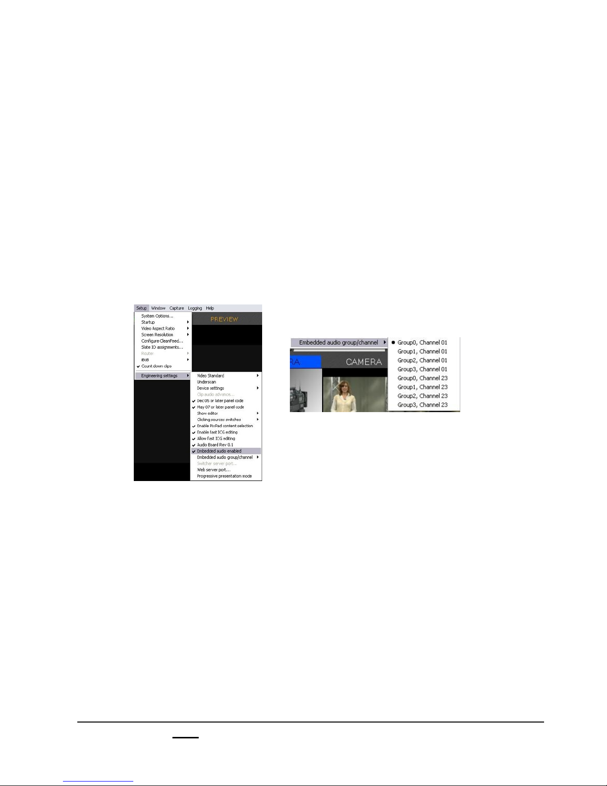
1.4 Audio I/O
All Slate systems do not do any internal audio mixing, all mixing needs to be done
externally. For automated control of external audio mixers, see section 7.12. One clip
store is included on the Slate 100 and Slate 1000. On a Slate 2100 and Slate 3000
two clip store channels are included. The clip store can be used with or without audio,
and can either have embedded audio in/out through the Slate SD-SDI in/outputs or
analog stereo audio through the 25 pin dim to XLR break out cable, which plugs into
the back of the workstation. Both the inputs and the outputs of the breakout cable use
a balanced line level signal.
To use embedded audio, in BPswitcher go to Setup, Engineering Settings and select
Embedded audio enabled, as shown below. You may also change the group/channel
in which the audio is embedded in the SDI stream in this same menu.
To use analog audio and to disable embedded audio, follow the same procedure as
stated above and deselect Embedded audio enabled.
The embedded audio input would come from a Digital Video Tape Deck or other
device that has embedded audio on the SDI video stream. All the SD-SDI Slate inputs
can accept embedded audio.
The analog audio input would come from a Video Tape Deck, DVD player, or any other
source. It is recommended to go though an audio mixer to adjust audio record levels.
For more information about recording to the Clip Store, see section 6.0.
The embedded audio output for each clip store can be assigned to any SD-SDI Slate
output, see section 1.2.8 to setup the embedded audio output. The audio would run to
a Digital Video Tape Recorder or an audio de-embedder.
The analog output would come out of the breakout cable (one channel is for Clip Store
channel 1 and the other is for the optional Clip Store channel 2, as labeled on the
breakout cable) and go into a audio mixer or recording device.
NOTE: For technical specifications of the pin-out of the analog audio breakout cable, see Appendix A.7.
The HD I/O card does not support embedded audio.
Broadcast Pix V7.0
install - concepts - PixMaster - switcher - CG - clips - controls - team - appendix
1.4
Page 28

1.5 Slate I/O Assignments
Inputs 1-8 on the Slate boards are general purpose video inputs that may be used for
cameras, VTRs, and feeds from servers and other external video devices. Any input/
output connected to the Slate video cards in the workstation needs to be configured
with this assignment window to ensure proper operation.
To Assign the Slate I/O:
1. Start the Broadcast Pix application by
clicking on it's switcher icon on the desktop,
which will bring up the large Broadcast Pix
switcher window, which contains a blank
Multi-View, and various drop down menus at
the top.
2.! On the Setup drop down menu, select Slate
IO assignments…
(Note: a show must be loaded to see this.
Go to File, Load Show).
And the Slate IO Assignments window will
appear as shown below.
Broadcast Pix V7.0
install - concepts - PixMaster - switcher - CG - clips - controls - team - appendix
1.5
Page 29
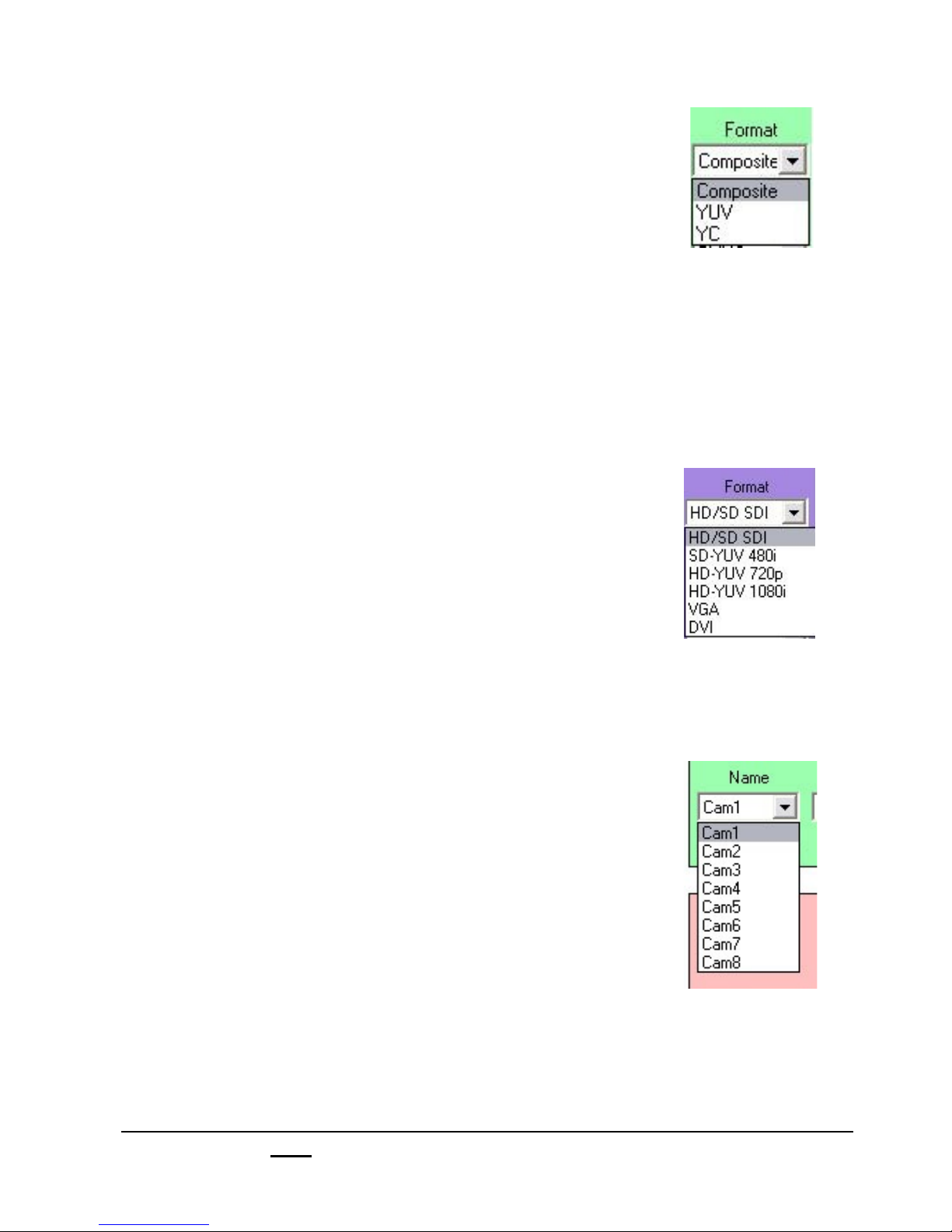
3.! Select the proper input settings in the top green and
purple sections.
If an analog card is installed, select the format that is
connected, either Composite for composite, YUV for
component/YPrPb or YC for S-Video.
If a digital card is installed, this option will be grayed out
as SDI, since all inputs will accept SD-SDI 480i/576i
video.
If a high-definition card is installed, inputs 1, 2, 3, 5, 6
and 7 will be grayed out as HD/SD-SDI, since those
inputs will accept SD-SDI 480i/576i, HD-SDI 720p or
HD-SDI 1080i video.
If a DVI card is installed, for inputs 4 and/or input 8
select either HD/SD-SDI for SD-SDI 480i/576i, HD-SDI
720p or HD-SDI 1080i,
SD-YUV 480i for analog component/YPrPb, HD-YUV
720p for analog HD 720p component/YPrPb, HD-YUV
1080i for analog HD 1080i component/YPrPb, VGA for
a VGA analog computer signal or DVI for DVI-I digital
computer signal.
Note: you can not input HD-SDI, HD/SD YUV and DVI/
VGA simultaneously, only one format per input per
show.
4. For each input select the name, which will determine
what name appears on the PixButton, Multi-View and
other identifiers for this source. In this example, Input 1
is being named Cam1, for Camera 1.
To create your own custom name, select Custom from
the drop down menu.
Broadcast Pix V7.0
install - concepts - PixMaster - switcher - CG - clips - controls - team - appendix
1.5
Page 30
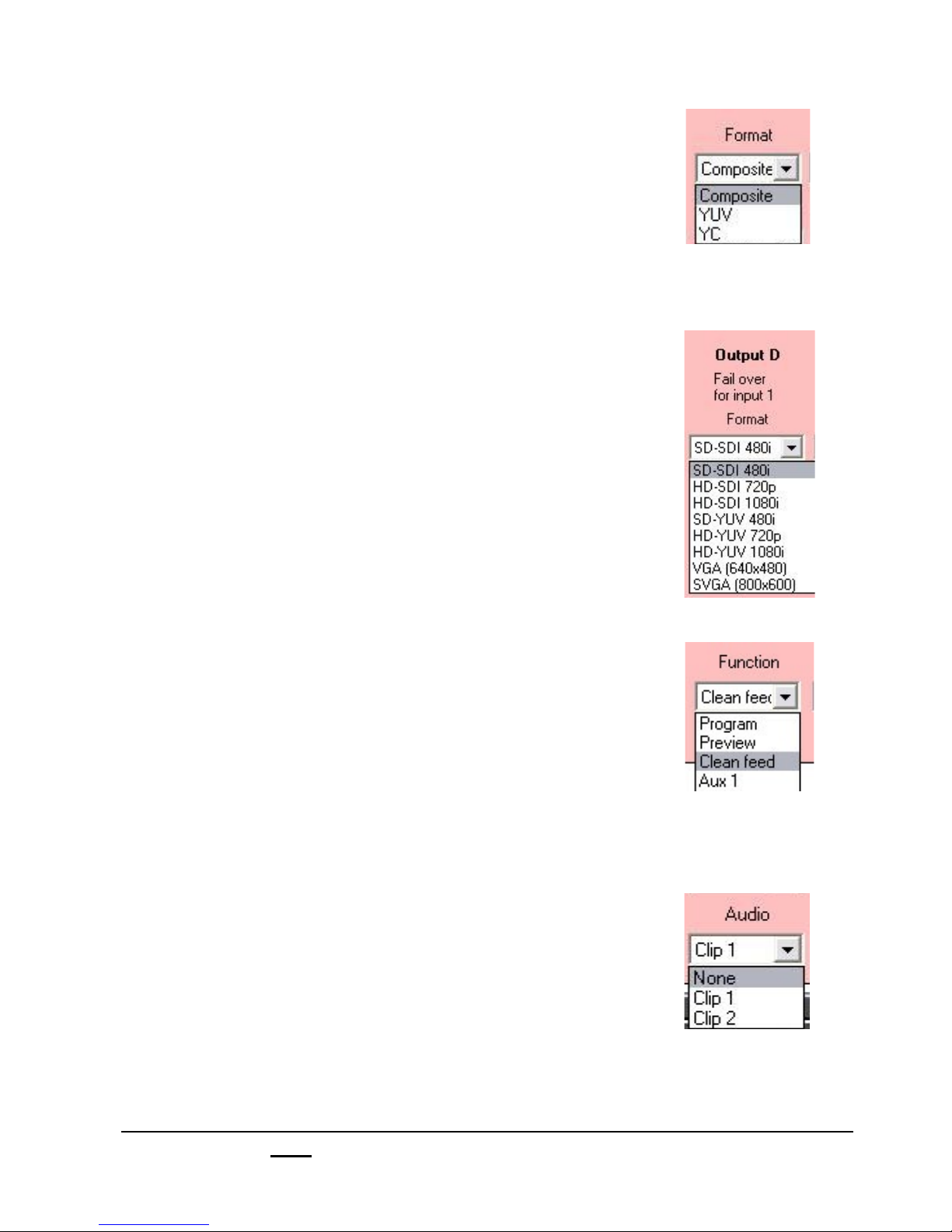
5.! Select the proper output settings in the bottom pink
section.
For each analog output select the format that is
connected, either Composite for composite, YUV for
component/YPrPb or YC for S-Video.
For digital outputs, this option will be grayed out as
SDI, since all outputs will accept SD-SDI 480i/576i
video.
If a high-definition card is installed, outputs D and/or E
are the only HD outputs. Select either SD-SDI 480i for
standard definition, HD-SDI 720p for high-definition
720p or HD-SDI 1080i for high-definition 1080i.
If a DVI card is installed, select either SD-YUV 480i for
analog component/YPrPb, HD-YUV 720p for analog
high-definition 720p component/YPrPb, HD-YUV 1080i
for analog high-definition 1080i component/YPrPb, DVI
1080p for high-definition 1080p through a DVI-HDMI
cable, or any of the computer output resolutions from
VGA (640x480) to DVI WUXGA (1920x1200).
Note: you can not output HD-SDI and DVI/VGA
simultaneously on the output.
6. For each output, assign it to Program, Preview, Clean
Feed (clean of any/all keys selectable from the Setup
Menu), or an auxiliary output. For example, in the
illustration Clean Feed is being selected.
7.! For each digital SD-SDI output select which clip store
audio will be outputted on the embedded SDI stream.
Either None, Clip 1 or Clip 2. To activate embedded
audio see section 1.2.7.
Note: you can not output embedded audio on a HD I/O
card.
8. Click on Save in the lower right corner of the Slate IO
Assignments window to save and exit.
Broadcast Pix V7.0
install - concepts - PixMaster - switcher - CG - clips - controls - team - appendix
1.5
Page 31
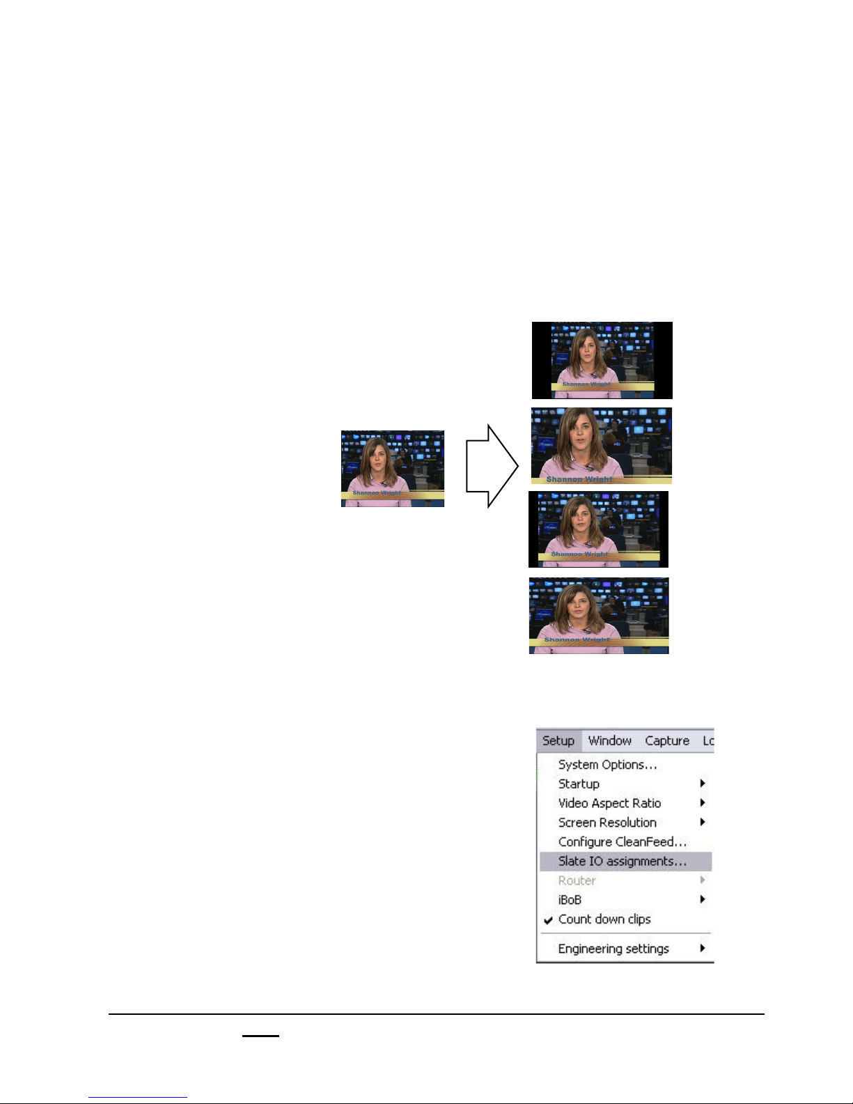
1.5.1 AutoAspect Inputs
AutoAspect solves the many challenges of mixing 4:3 and 16:9 content in the same
production. It enables 16:9 and 4:3 inputs to be used interchangeably and mixed
together in the same live production, while maintaining the native aspect ratio of each
element rather than stretching them. Each input can be set to one of 4 aspect
treatments, three of which preserve the native aspect ratio. Conventional switchers
can only stretch video when crossing aspect ratios, causing people to look too wide
or too thin.
This Illustration below
shows the four ways that a
4:3 source can be treated in
Box
a 16:9 production. If None
is selected, then the image
is stretched to fill the space,
as is done on other
switchers, and the result
4
ways
Crop
makes the person look too
wide. If one of the other
three treatments are
14:9
selected than the original
aspect ratio of the source is
preserved, and the person
does not look too wide.
None
(Stretch)
To set the aspect treatment of a source:
1. In the Broadcast Pix Switcher, launch a
show from the Multi-View. (File, Load
show)
2. On the Setup drop down window, shown in
the illustration at the right, click on Slate IO
assignments…, and the Slate IO
assignments window will open as shown on
the next page.
Broadcast Pix V7.0
install - concepts - PixMaster - switcher - CG - clips - controls - team - appendix
1.5.1
Page 32
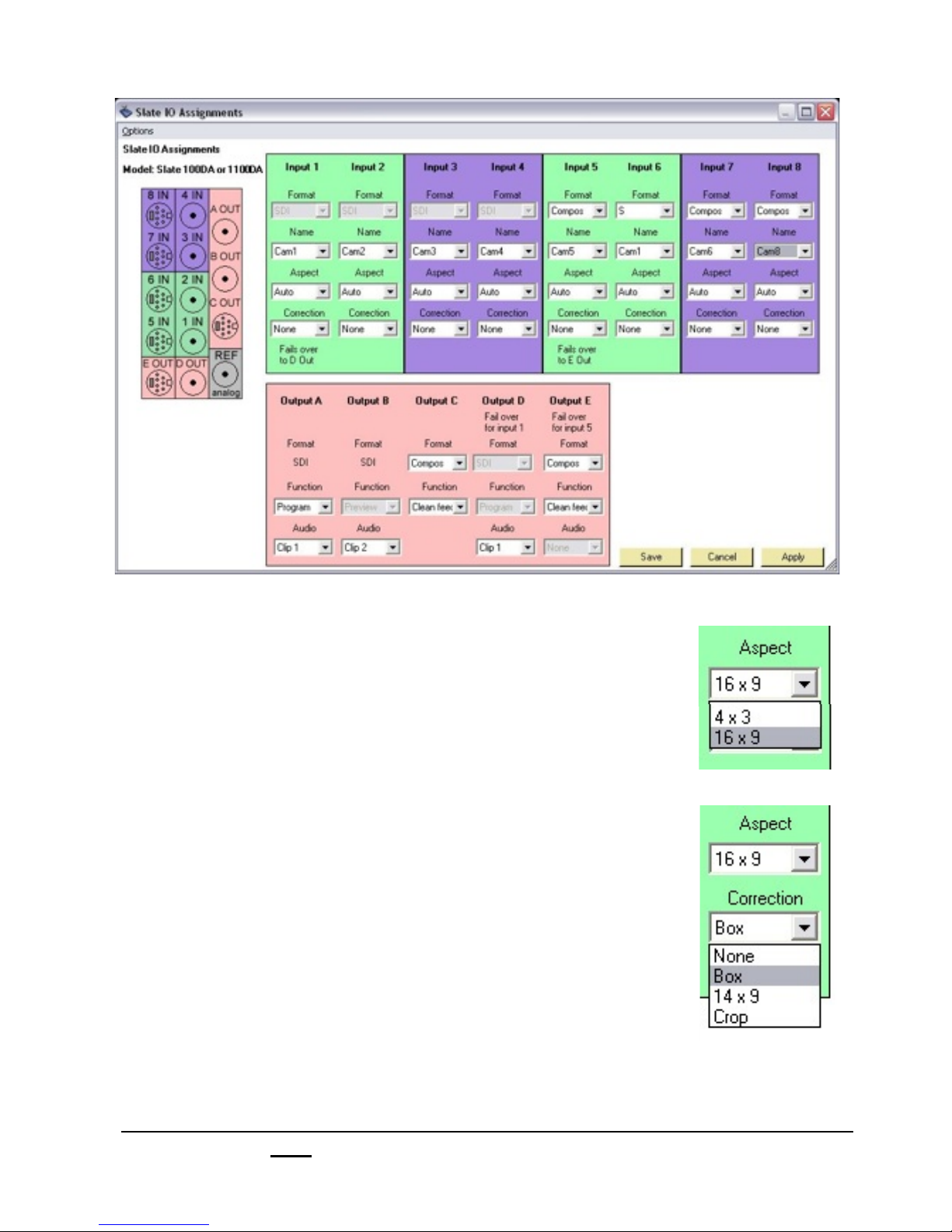
3.! Use the Aspect drop down menu to indicate the
native aspect ratio of the source.
4. Use the Correction drop down menu to select the
desired treatment that will be applied when using this
source in a production of the other size than its native
size.
5.! Press Apply to see your changes applied to the
sources temporarily, if satisfied click Save to close the
Slate IO Assignments window.
6.! You may also set these settings from the control panel
with Source Controls, see section 4.6.
NOTE: When the show is set to the same aspect ratio as the source’s native
aspect ratio, then no aspect treatment will be performed. When the show is
set to the opposite aspect ratio, than the selected treatment will be applied.
See section 1.13.3 for setting the show’s aspect ratio.
NOTE: When a source is treated, it will appear with that treatment on all
video outputs, and on the program and preview windows of the Multi-View.
Broadcast Pix V7.0
install - concepts - PixMaster - switcher - CG - clips - controls - team - appendix
1.5.1
Page 33

1.6 Broadcast Pix Slate 2100
1.6.1 Slate 2100 System Contents
The Broadcast Pix Slate 2100 is comprised of the following components:
Broadcast Pix Software,
Showing the Multi-View
Software:
BPSwitcher V7
Inscriber TitleMotion Pro
Character Generator
(VGA monitor
not included )
Broadcast Pix
Control Panel
Broadcast Pix
SoftPanel
Microsoft Windows XP
Workstation with Slate boards
Intelligent Break-out-Box (iBoB)
Broadcast Pix V7.0
install - concepts - PixMaster - switcher - CG - clips - controls - team - appendix
Keyboard, Mouse and 10/100 Ethernet
switch and network and serial cables
1.6
Page 34

Broadcast Pix 2100 System Includes:
Hardware
Broadcast Pix physical control panel (Control panel)
Broadcast Pix Break-out-Box (iBoB)
Workstation, with Slate board and I/O board
Ethernet 10/100 switch (for private control network)
(3) Straight Network Cables (for private control network)
9-Pin Male to Female Straight Serial Cable (for fail-safe control)
Inscriber USB Dongle, installed internally in the workstation at the factory
PS2 Keyboard
USB Mouse
Software
Broadcast Pix Software V7
Inscriber TitleMotion Pro Character Generator
Microsoft Windows XP Service Pack 2 and .NET 1.1 & 2.0
Requirements
To install a system you will also need:
At least one VGA monitor (at least 1280x1024 resolution)
Sync Generator or other source of house black burst (analog reference)
Broadcast Pix V7.0
install - concepts - PixMaster - switcher - CG - clips - controls - team - appendix
1.6.1
Page 35

1.6.2 Wiring the Slate 2100
1. Attach analog reference/blackburst. Run one wire from your sync generator to
the Break-out-Box’s (iBoB) reference input, and then run a second wire from the
iBoB’s reference output to the ‘Ref’ input on the Slate switcher card, as shown on
the wiring diagram on the next page. You may use the other ‘Ref Outs’ to feed
your cameras, tape machines or other sources that accept genlock.
2. Attach six BNC video cables between the Slate cards and the iBoB:
On Switcher board (right) On iBoB
A From A
B From B
I/O
In S4
In S3
Switcher
Out A
Out B
On I/O board (left) On iBoB
S1 To S1
S2 To S2
In S2
Out C
In S1
S3 To S3
S4 To S4
Out D
Ref
3. Attach the following BNC video cables on the iBoB, if desired:
Inputs 1-8 to cameras, tape machines and other sources
Preview to a preview monitor
Program to a program monitor and other program destinations
4.! Attach three network cables (Cat 5) from the private Ethernet 10/100 switch to the
Broadcast Pix components, as follows:
From Hub
Any port To workstation NIC 2, next to the USB ports
Any port To control panel - either network connector
Any port To iBoB - either network connector
NOTE: The workstation has two network connections, the above NIC1 and a 1GB NIC2. NIC2
connects the system to a “house” network, which is convenient for moving content into the system.
Do not move data through the private network hub, as it will affect system performance.
5. Attach the RS-232 serial cable from the control panel to the iBoB serial input
labeled ‘Panel’. See section A.8 for pin-out.
6. Attach the Workstation’s VGA monitor(s), mouse and keyboard.
7. Plug in power to the workstation, iBoB and control panel.
8. See Section 1.3.5 to set the inputs on the iBoB for format, name and timing.
Broadcast Pix V7.0
install - concepts - PixMaster - switcher - CG - clips - controls - team - appendix
1.6.2
Page 36

1.6.2 Wiring Diagram for Slate 2100 switcher
Sync Generator
VGA
Monitor(s)
Network Switch
10/100 for
Broadcast Pix
Network control
Broadcast Pix V7.0
Workstation
S4
S8
NIC 1
1GB
NIC 2
1GB
S7
S6
S5
E
Network
for moving
content
Control Panel
install - concepts - PixMaster - switcher - CG - clips - controls - team - appendix
A
S3
B
S2
C
S1
D
Key
Wires
Connectors
Switcher Cards
REF
Fail-Safe
Serial Cable
Video
Ethernet
Serial
BNC
Network
Serial
1.6.2
Page 37
Wiring the Optional 9-12 inputs on a Slate 2100
The Slate 2100 can be fitted with an optional second Slate I/O board, which expands
the number for video inputs and outputs. This second board fits in the left slot as
shown below and can be ordered in either SD-SDI, HD/SD-SDI or Analog. Live inputs
1-8 attach to the iBoB and inputs 9-12 attached directly to this left Slate card. All the
inputs and outputs of the iBoB are Standard Definition (SD) only, however you can mix
High Definition (HD) content with the iBoB using the optional HD I/O card in the
second card slot.
Slate Board Set
(left I/O board is optional)
left
I/O
In 12
In 11
center
I/O
In S4
In S3
Right
Switcher
Out A
Out B
In 10
In 9
Out E
In S2
In S1
Out D
Out C
Ref
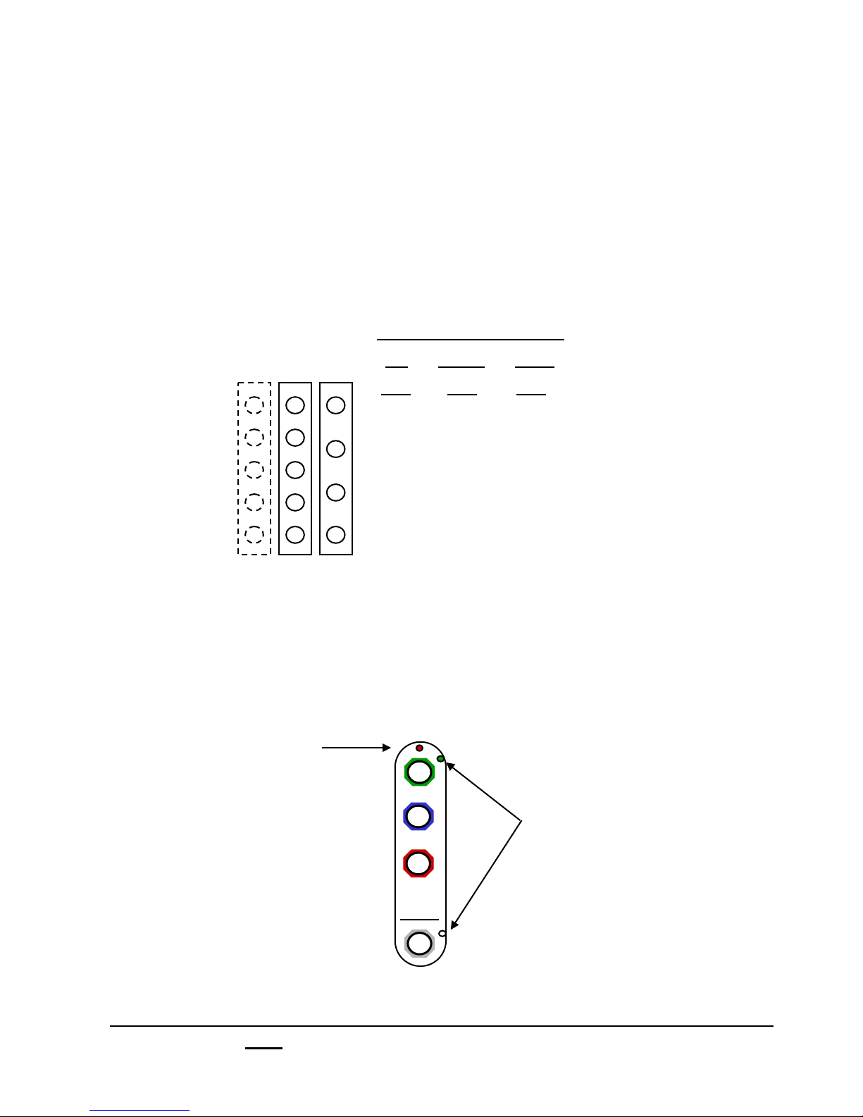
Input/Output Status Lights on iBoB
The iBoB has status indicator leds (Light Emitting Diodes) that show at all times the
status of each input, including its presence, timing and format. Inputs 1-4 also have
an led that indicates what analog format the input is set to, and there are similar
indicators on the outputs that can be either component or composite.
Analog Input Leds:
green composite
orange Y/C
red component
off digital
Input Leds
green on – synchronous source
Analog Output Leds:
There are similar status Leds for
program and preview to indicate
whether analog component or Y/C
has been selected.
Broadcast Pix V7.0
install - concepts - PixMaster - switcher - CG - clips - controls - team - appendix
1
blink on – asynchronous source
off no input
1.6.2
Page 38

1.6.3 Audio I/O Wiring for the Slate 2100
All Slate systems do not do any internal audio mixing, all mixing needs to be done
externally. For automated control of external audio mixers, see section 7.12. There are 2
channels of Clip Store on a Slate 2100 and both may be used with or without audio. On a
2100 audio is handled in 3 standards: either embedded on a SD-SDI stream, Analog
Stereo (Left/Right) or Digital (AES/EBU) with the provided XLR connections on the
Break-out-Box.
The iBoB acts as an audio de-embedder, in order for any audio to work on the iBoB, you
must enable embedded audio, see section 1.4. The iBoB audio inputs and outputs have a
balanced line level signal.
Audio in to the iBoB, for recording/ingesting to the Clip Store, can be either one of the 3
standards. Either embedded on 1 of the 8 SDI inputs, Analog Stereo or Digital. For more
information about recording to the Clip Store, see section 6.0.1.
Audio is outputted from the iBoB in the same 3 standards and all 3 are always active.
Embedded on the Program (Clip 1) and Preview (Clip 2) SDI outputs, Analog Stereo and
Digital AES/EBU with the provided XLR connections.
iBoB Audio
Analog Left/
Right Input
For Recording
to the Clip Store
Digital
AES/EBU Input
For Recording
to the Clip Store
Analog Left/
Right
Output
For Playing
Clip Store 1
Analog Left/
Right
Output
For Playing
Clip Store 2
AES/EBU
For Playing
Clip Store 1
Digital
Output
Digital
AES/EBU
Output
For Playing
Clip Store 2
Broadcast Pix V7.0
install - concepts - PixMaster - switcher - CG - clips - controls - team - appendix
1.
Page 39

1.6.4 iBoB Tally Wiring
The iBoB includes a tally connector to use with external tally lights like on a studio
camera. The first 8 connectors correspond to Inputs 1 – 8 on the iBoB. Run a set of wires
from each connector on the iBoB to each terminal on the camera/camera unit, one to
Program and the other to the Ground, as shown below. The ‘Gnd’(Ground) terminal on
the iBoB is used only for the ‘Gpi’ (General Purpose Input) terminals.
If you have an optional input card and would like to tally sources 9-12, you may use the
optional tally box used on a Slate 100/1000. Inputs 9-12 correspond to terminals 4-7 on
the tally box. See section 1.3.3 for more information.
Tally
Gnd
Gpi2
Gpi1
8
7
6
5
4
3
2
1
CAMERA 1
CAMERA 2
CAMERA 3
* Camera Control Unit will vary depending on manufacturer.
NOTE: The iBoB does not supply any voltage for tally. Voltage must be provided by your Camera Control
Units or other source. The iBoB only opens and closes the tally circuit. Refer your Camera Control Unit’s
user manual for more information.
Broadcast Pix V7.0
install - concepts - PixMaster - switcher - CG - clips - controls - team - appendix
1.6.4
Page 40
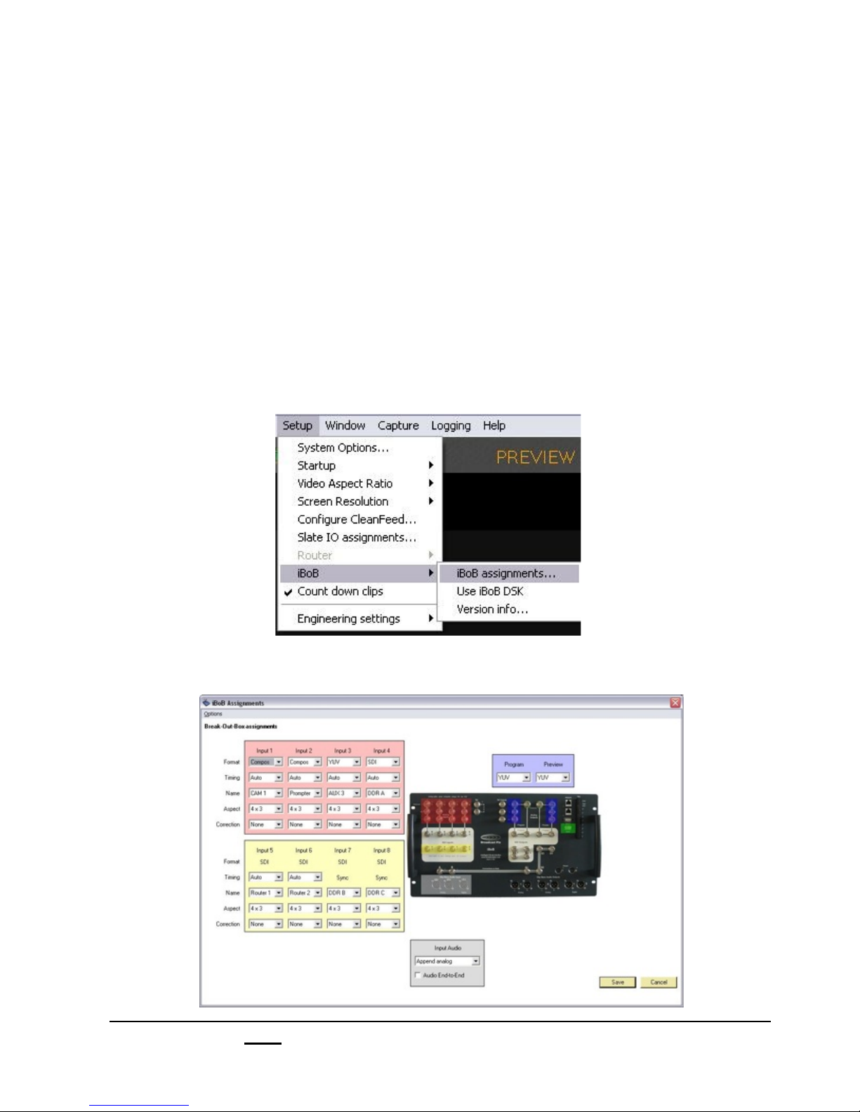
1.6.5 iBoB Assignments
Inputs 1-8 on the iBoB are general purpose video inputs that may be used for cameras,
VTRs, and feeds from servers and other external video devices. They are set up using
the following steps, or from the Control panel as described in section 1.3.6.
To Assign the iBoB I/O:
1.! Start the Broadcast Pix application by clicking on the switcher icon on the
desktop, which will bring up the large Broadcast Pix switcher window, which
contains a blank Multi-View and various drop down menus at the top.
2.! On the Setup drop down menu, select iBoB, then iBoB assignments…, as
shown below. A show will need to be loaded to access this menu.
The iBoB Assignments window will appear as shown below.
Broadcast Pix V7.0
install - concepts - PixMaster - switcher - CG - clips - controls - team - appendix
1.6.5
Page 41
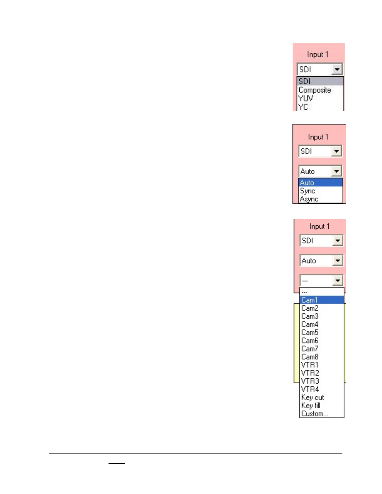
3.! For inputs 1 through 4, select the appropriate video
format either SDI for digital, Composite for analog
composite, YUV for component/YPrPb or YC for S-video.
Inputs 5 through 8 are always set to SDI for digital.
4.! For inputs 1 through 6, select the reference timing either
Auto for the iBoB to auto-detect genlock, Sync for timed/
genlocked sources or Async for untimed/non-genlocked
sources such as a DVD player.
Inputs 7 and 8 are always set to Sync and need timed
sources plugged into them for the video to work properly.
5. For each input select the name, which will determine
what name appears on the PixButton, Multi-View and
other identifiers for this source. In this example, Input 1 is
being named Cam1, for Camera 1.
To create your own custom name, select Custom from
the drop down menu. See next page for more
information.
6.! If you are combining 16:9 and 4: 3 sources, then you
may treat the Aspect ratio of each input. Use the iBoB
Assignments window to treat sources 1-8, use the Slate
IO assignments window to treat optional sources 9-12,
see section 1.5
You may also treat the sources with the Source Controls
from the control panel, see section 4.6
Broadcast Pix V7.0
install - concepts - PixMaster - switcher - CG - clips - controls - team - appendix
1.6.5
Page 42

7.! If you would like to customize the names of the inputs that will appear on the
PixButtons, then select Custom in the above menu and the Add source name
window will appear as shown below. Enter the Name desired, Number (if no
number is desired then enter ‘0’) and select an icon using the Icon drop down
menu, either Camera, VTR or None, and then click OK.
If you want this name to appear on the PixButtons, you will need to select the
Options menu and select Use name on live source buttons as shown below.
If this option is not selected, then only the input number and icon will appear
for all source PixButtons.
8. One of the analog Preview and Program outputs is selectable between YC for
S-Video and YUV for Component/YPrPb video. (The other three preview
outputs are have fixed formats: one is always analog Composite, and the other
two are always SD-SDI). For the selectable analog output, use the drop down
window to select the desired format. For example, in the illustration below YUV
is being selected for Program and Preview.
Broadcast Pix V7.0
install - concepts - PixMaster - switcher - CG - clips - controls - team - appendix
1.6.5
Page 43

9. Click on Save in the lower right corner of
the iBoB assignments to apply your changes.
10. If you have optional inputs 9 -12, then you can set up these extra inputs by
opening the Slate IO Assignments window from the Setup drop down menu,
as shown here.
NOTE: If you wish to set up iBoB DSK, see sections 4.8.
Broadcast Pix V7.0
install - concepts - PixMaster - switcher - CG - clips - controls - team - appendix
1.6.5
Page 44
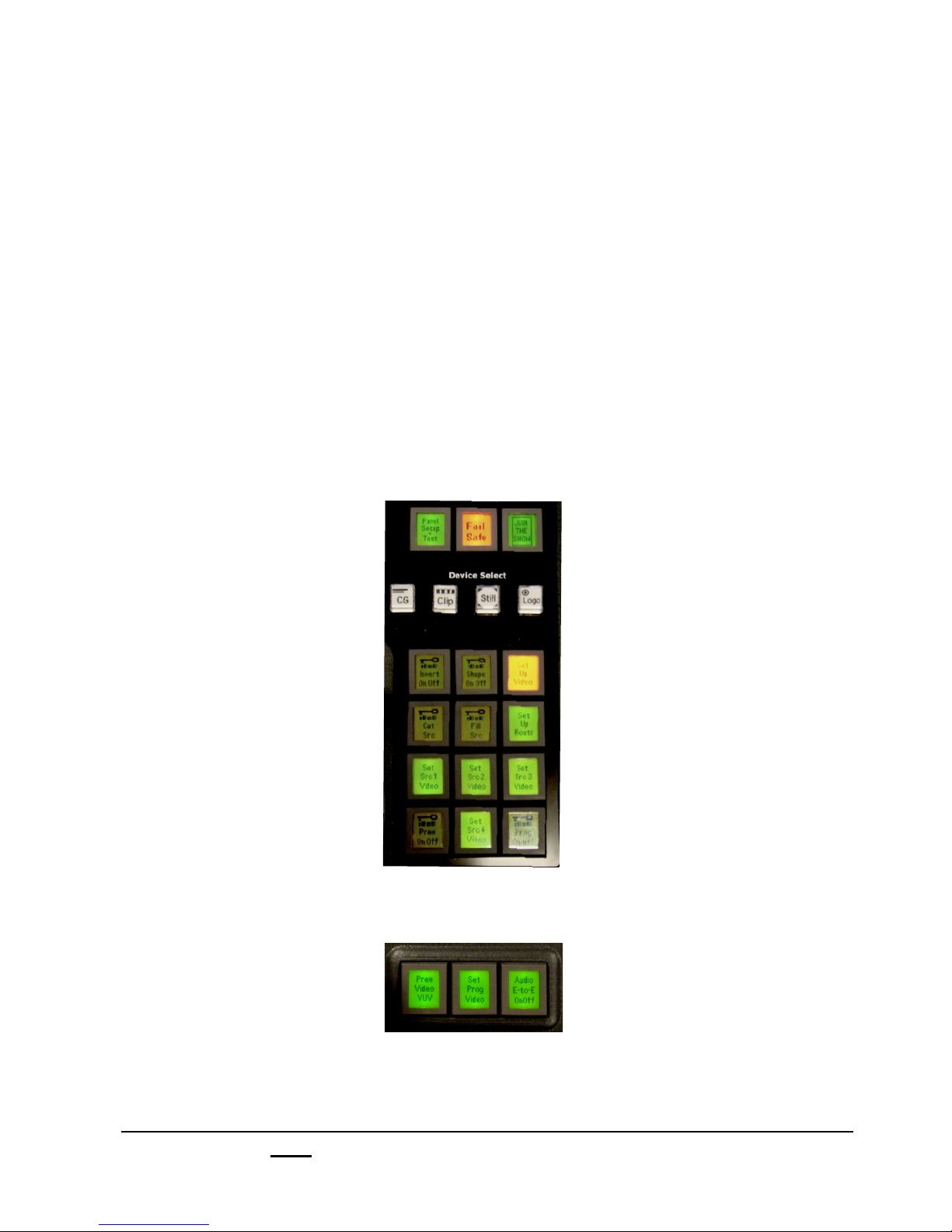
1.6.6 Setting up the iBoB from the Control Panel
As an alternative, the iBoB can have its analog formats chosen from the control panel.
This is handy if the workstation is not on or unavailable for some reason.
1.! While the control panel is offline, select the Fail Safe PixButton in the Wildcard
Device Select section.
NOTE: To force the panel to go offline, select the Shift button, followed by the MEM button. This
will activate the first Wildcard Device button to read GO OFF LINE.
2.! Select the Set Up Video button in the PixPad. This will bring up a new set of
PixButtons, one for each input.
3.! Press the Set Src Video button for sources 1-4 until the desired source is
selected. Either Digital, Cmpos, Y/C or YUV.
4.! You may also select the video output for Preview and Program as shown below.
Either Y/C or YUV.
NOTE: In this same setup you may also assign the Key Cut/Fill for the iBoB DSK.
Broadcast Pix V7.0
install - concepts - PixMaster - switcher - CG - clips - controls - team - appendix
1.6.6
Page 45

1.7 Broadcast Pix Slate 3000
1.7.1 Slate 3000 System Contents
The Broadcast Pix Slate 3000 is comprised of the following components.
Broadcast Pix Software,
Showing the Multi-View
Software:
BPSwitcher V7
Inscriber TitleMotion Pro
Character Generator
(VGA monitor
not included )
Broadcast Pix
Control panel
Broadcast Pix
SoftPanel
Microsoft Windows XP
Workstation with Slate boards
Router
Either HD or SD
16 or 32 inputs
Broadcast Pix V7.0
install - concepts - PixMaster - switcher - CG - clips - controls - team - appendix
Keyboard, Mouse and 10/100 Ethernet
switch and network and serial cables
1.7
Page 46

Broadcast Pix 3000 System Includes:
Hardware
Broadcast Pix physical control panel (Control Panel)
Broadcast Pix Router, made by Harris, either 16x16 or 32x32 (HD or SD)
Workstation, with Slate board and I/O board
Ethernet 10/100 Switch (for private control network)
(3) Straight Network Cables (for private control network)
9-Pin Male to Female Straight Serial Cable (for fail-safe control)
6 Ft BNC Cable Bundles (to connect between router and workstation)
25-Pin to 6-XLR Audio Breakout Cable (for analog audio I/O)
Inscriber USB Dongle, installed internally in the workstation at the factory
PS2 Keyboard
USB Mouse
Software
Broadcast Pix Software V7
Inscriber TitleMotion Pro Character Generator
Microsoft Windows XP Service Pack 2 and .NET 1.1 & 2.0
Requirements
To install a system you will also need:
At least one VGA monitor (at least 1280x1024 resolution)
Sync Generator or other source of house black burst (analog reference)
Broadcast Pix V7.0
install - concepts - PixMaster - switcher - CG - clips - controls - team - appendix
1.7.1
Page 47

1.7.2 Wiring the Slate 3016dd & 3016hh
1. Attach analog reference/blackburst. Run one wire from your sync generator to
the Router’s ‘Sync’ input, and then run a second wire from the Router’s ‘Sync’
output to the ‘Ref’ input on the Slate, as shown on the wiring diagram on the next
page.
2. Attach the (3) supplied BNC cable bundles between the Slate Cards and the
Router, as labeled:
On Switcher boards On Router
A - SD only (right) Input 16
B - SD only (right) Input 15
D - HD or SD (center) Input 14
E - HD or SD (left) Input 13
On I/O board (center) On Router
S1 Output 16
S2 Output 15
S3 Output 14
S4 Output 13
On I/O board (left) On Router
S5 Output 12
S6 Output 11
S7 Output 10
S8 Output 9
3.! Attach the following video cables on the Router, if desired:
Inputs 1-12 to cameras, tape decks and other sources
Program, Output 1 to a program monitor and other program destinations
Preview, Output 2 to a preview monitor
Auxes, Output 3-8 to auxiliary outputs
4.! Attach three network cables (Cat 5) from the private Ethernet 10/100 switch to th
Broadcast Pix components, as follows:
From Hub
Any port To workstation NIC 2, next to the USB ports
Any port To control panel - either network connector
Any port To Router ‘ENET’ connector
NOTE: The workstation has two network connections, the above NIC1 and a 1GB NIC2. NIC2
connects the system to a “house” network, which is convenient for moving content into the system.
Do not move data through the private network hub, as it will affect system performance.
5. Attach the RS-232 serial cable from the control panel to the Router’s serial input
labeled ‘SERIAL’. See section A.8 for pin-out.
6. Attach the Workstation’s VGA monitor(s), mouse and keyboard.
7. Plug in power to the workstation, Router and control panel.
8. See Section 1.4.5 to set the inputs on the Router for name and timing.
Broadcast Pix V7.0
install - concepts - PixMaster - switcher - CG - clips - controls - team - appendix
1.7.2
Page 48
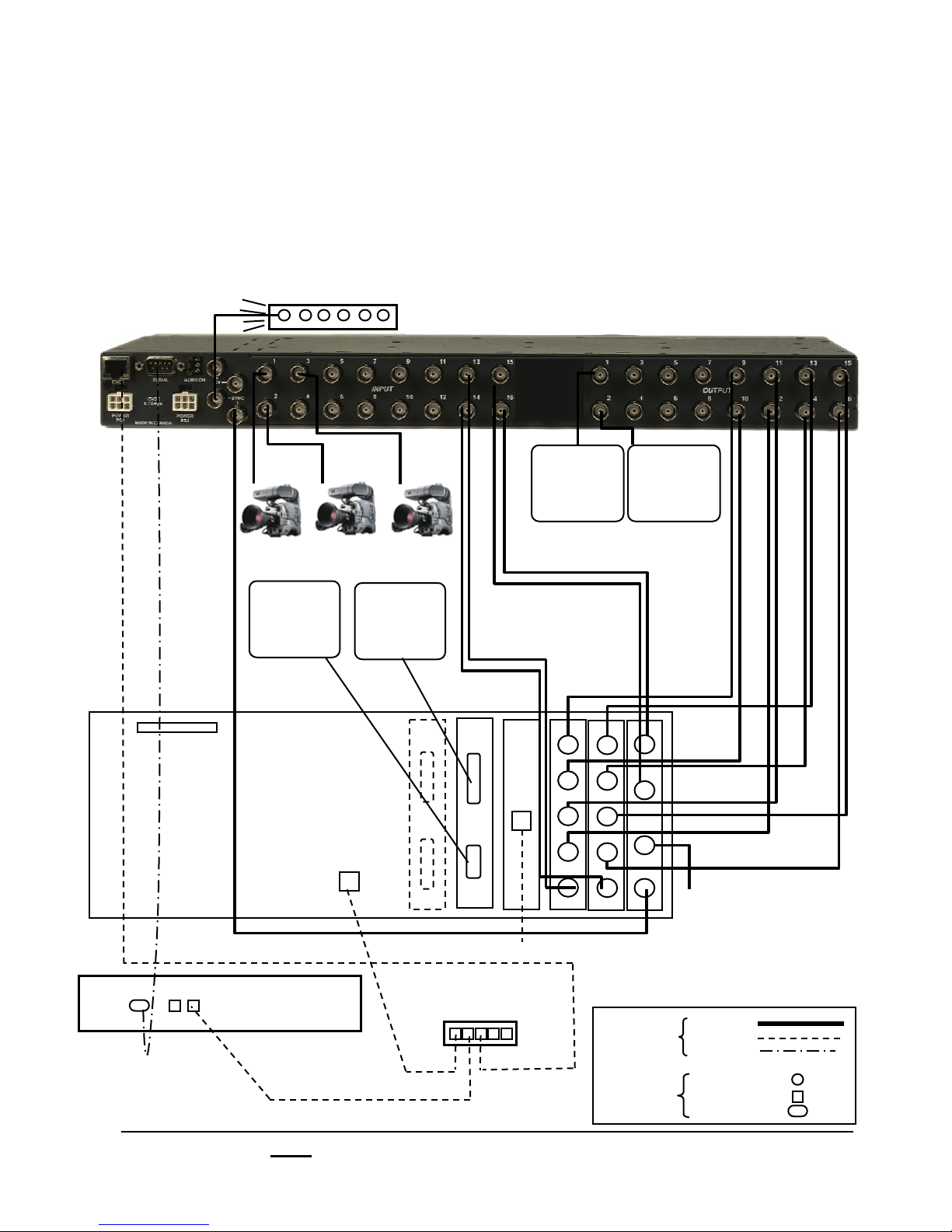
1.7.2 Wiring Diagram for Slate 3016dd & 3016hh
A Slate 3016dd uses a 16x16 SD router, which connects to two digital Slate input cards.
A Slate 3016hh uses a 16x16 HD router, which connects to two HD Slate input cards. A
Slate 3016hh has only two HD outputs, Preview and/or one Aux output are in standard
definition only. If a DVI/VGA output is in use then the HD-SDI is no longer active. These
settings are all set in the Slate I/O Assignments window, see section 1.5.
Sync Generator
16x16 Router
25-Pin Dim
for analog I/O cable
Fail-Safe
Serial Cable
VGA
Monitor
Workstation
NIC 2
10/100MB
Control Panel
DVI
Monitor
Network for moving content
Network Switch
for Broadcast Pix control
NIC
1GB
Program
Monitor
S4
S8
S3
S7
S2
S6
S5
S1
D
E
Key
Wires
Connectors
Preview
Monitor
A
B
C
REF
Out C:
Separate Analog
Output for Clean
Feed, Program or
Preview.
See section 1.5
Video
Ethernet
Serial
BNC
Network
Serial
Broadcast Pix V7.0
install - concepts - PixMaster - switcher - CG - clips - controls - team - appendix
1.7.2
Page 49

1.7.3 Wiring the Slate 3032dd & 3032hh
1. Attach analog reference/blackburst. Run one wire from your sync generator to
the Router’s ‘Sync’ input, and then run a second wire from the Router’s ‘Sync’
output to the ‘Ref’ input on the Slate, as shown on the wiring diagram on the next
page.
2. Attach the (3) supplied BNC cable bundles between the Slate Cards and the
Router:
On Switcher boards On Router
A - SD only (right) Input 32
B - SD only (right) Input 31
D - HD or SD (center) Input 30
E - HD or SD (left) Input 29
On I/O board (center) On Router
S1 Output 32
S2 Output 31
S3 Output 30
S4 Output 29
On I/O board (left) On Router
S5 Output 28
S6 Output 27
S7 Output 26
S8 Output 25
3.! Attach the following video cables on the Router, if desired:
Inputs 1-28 to cameras, tape decks and other sources
Program, Output 1 to a program monitor and other program destinations
Preview, Output 2 to a preview monitor
Auxes, Output 3-24 to auxiliary outputs
4.! Attach three network cables (Cat 5) from the private Ethernet 10/100 switch to th
Broadcast Pix components, as follows:
From Hub
Any port To workstation NIC 1, next to the USB ports
Any port To control panel - either network connector
Any port To Router ‘ENET’ connector
NOTE: The workstation has two network connections, the above NIC1 and a 1GB NIC2. NIC2
connects the system to a “house” network, which is convenient for moving content into the system.
Do not move data through the private network hub, as it will affect system performance.
5. Attach the RS-232 serial cable from the control panel to the Router’s serial input
labeled ‘SERIAL’. See section A.8 for pin-out.
6. Attach the Workstation’s VGA monitor(s), mouse and keyboard.
7. Plug in power to the workstation, Router and control panel.
8. See Section 1.4.5 to set the inputs on the Router for name and timing.
Broadcast Pix V7.0
install - concepts - PixMaster - switcher - CG - clips - controls - team - appendix
1.7.3
Page 50
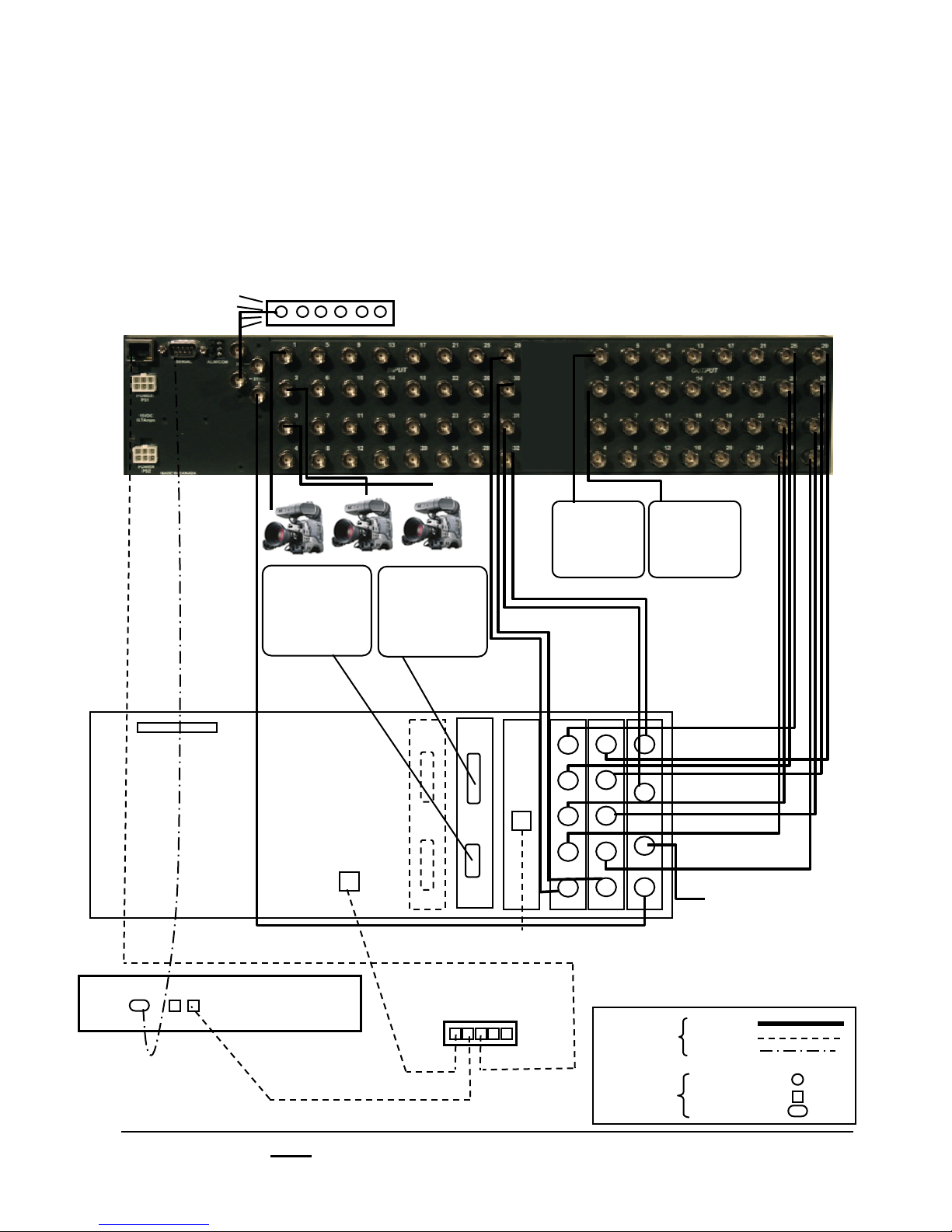
1.7.3 Wiring Diagram for Slate 3032dd & 3032hh
A Slate 3032dd uses a 32x32 SD router, which connects to two digital Slate input cards. A
Slate 3032hh uses a 32x32 HD router, which connects to two HD Slate input cards. A
Slate 3032hh has only two HD outputs, Preview and/or one Aux output are in standard
definition only. If a DVI/VGA output is in use then the HD-SDI is no longer active. These
settings are all set in the Slate I/O Assignments window, see section 1.5.
Sync Generator
32x32 Router
25-Pin Dim
for analog I/O cable
Fail-Safe
Serial Cable
VGA
Monitor
Workstation
NIC 2
10/100MB
Control Panel
DVI
Monitor
S8
NIC
S7
1GB
S6
S5
E
Network for moving content
Network Switch
for Broadcast Pix control
Program
Monitor
A
S4
S3
B
S2
C
S1
D
Key
Wires
Connectors
Preview
Monitor
REF
Out C:
Separate Analog
Output for Clean
Feed, Program or
Preview.
See section 1.5
Video
Ethernet
Serial
BNC
Network
Serial
Broadcast Pix V7.0
install - concepts - PixMaster - switcher - CG - clips - controls - team - appendix
1.7.3
Page 51

1.7.4 Multiple Slate Wiring
A unique option with the Broadcast Pix Slate 3016 or 3032 is the capability to hook two
or more Slate systems to one centralized router to share inputs and outputs. Great for
larger facilities where multiple studios/control points are needed, it greatly simplifies
wiring by having one access point for all your connections and lowers your overall cost.
Instead of purchasing two or three separate units, purchase one large system and
increase your productivity.
There several types of productions where multiple Slates would come into play. The
first is having a low cost (without lacking any features) Studio B where you have a
complete separate system to feed a different program, with access to Studio A sources
if they are every needed. Other productions for this wiring method is for multi-cast. In
this new era of technology studios are asked to output the same production to two
different mediums, maybe one is for broadcast and the other for in-house IMAG (image
magnification), web-cast, mobile, closed-circuit TV, etc. Although the content is virtually
the same the final output needs to be different. For example web-casts are typically
smaller in size/resolution so compositions need to be less complex as they are also
less forgiving when it comes to fast motion and smaller fonts. For example, the studio
diagram below shows a Slate 3032 controlling a broadcast output and a Slate 1000
controlling a less complex web-cast.
There are a total of 24 external live inputs that are either independent or shared across
both systems, and 8 outputs for each system (Preview/Program & Auxes). Both control
panels, workstations and router connect to the same 100BASE-TX network switch,
using a total of 5 ports. Fail-safe switching, however, can only be dedicated to one
system, as the secondary system will have only 1 input outputted for fail-safe. See
diagram on next page.
As there are many ways to connect multiple Slate systems, it is advised to contact a
Broadcast Pix representative for more information.
Common Inputs
Cameras and other external sources
Broadcast Pix 32x32 Router
TV
WEB
Slate 1000
Broadcast Pix V7.0
Slate 3032
install - concepts - PixMaster - switcher - CG - clips - controls - team - appendix
1.7.4
Page 52

1.7.5 Example Slate 3032 & Slate 1000 Wiring
Straight serial fail-safe cable to primary control panel
Inputs Outputs
Blackburst
Serial In
Network In
Ref In
()$*+,-+./$%&'$)$
In 1
In 2
In 3
In 4
In 5
In 6
In 7
In 8
In 9
In 10
In 11
In 12
In 13
In 14
Live Inputs
(Cameras, tape decks, servers, etc.)
In 15
In 16
In 17
In 18
In 19
In 20
In 21
In 22
In 23
In 24
In 25
In 26
In 27
In 28
In 29
In 30
In 31
In 32
32x32 Router
!"#$%&'$
()$*+"01"2$%&'$3$
()$4&5$%&'$6$
()$4&5$%&'$7$
()$4&5$%&'$8$
()$4&5$%&'$9$
()$4&5$%&'$:$
()$4&5$%&'$;$
(3$*+,-+./$%&'$<$
(3$*+"01"2$%&'$)=$
(3$4&5$%&'$))$
(3$4&5$%&'$)3$
(3$4&5$%&'$)6$
(3$4&5$%&'$)7$
(3$4&5$%&'$)8$
(3$4&5$%&'$)9$
(>.'"$3$%&'$):$
(>.'"$3$%&'$);$
(>.'"$3$%&'$)<$
(>.'"$3$%&'$3=$
(>.'"$3$%&'$3)$
(>.'"$3$%&'$33$
(>.'"$3$%&'$36$
(>.'"$3$%&'$37$
(>.'"$)$%&'$38$
(>.'"$)$%&'$39$
(>.'"$)$%&'$3:$
(>.'"$)$%&'$3;$
(>.'"$)$%&'$3<$
(>.'"$)%&'$6=$
(>.'"$)$%&'$6)$
(>.'"$)$%&'$63$
Slate 3032
Outputs
Inputs Outputs
Slot 1
Out A
Out B
Ref In
Slot 2
In 1
Out C
Out D
In 2
In 3
In 4
In 5
Slot 3
Out E
In 6
In 7
In 8
Slate 1 Workstation
Inputs Outputs
Slot 1
Out A
Out B
Ref In
Slot 2
In 1
Out C
Out D
In 2
In 3
In 4
Slot 3
In 5
Out E
In 6
In 7
In 8
Slate 2 Workstation
Analog Output
Slate 1000 Outputs
Analog Output
Broadcast Pix V7.0
install - concepts - PixMaster - switcher - CG - clips - controls - team - appendix
1.7.5
Page 53
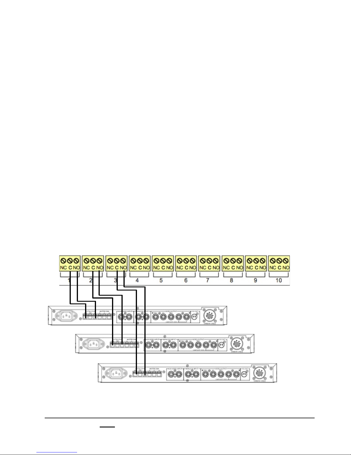
1.7.6 Optional Tally Box Wiring
The tally box option is a stand-alone Measurement Computing USB-ERB24 tally box, with
24 relay contacts for up to 24 camera/sources. It fits into a standard 19” wide rack and
comes standard with racking ears and uses convenient screw terminals that accepts cable
from 12 to 22 AWG. Each contact is rated a 6 amps at 240 volts AC. The box uses one of
the computers USB ports, and needs to be plugged into an electrical socket with the
supplied power supply. This tally box does not have GPIOs, if needed, then the tally box
from a Slate 100/1000 needs to be used for this purpose and can be used in conjunction
with a Slate 3000 tally box.
Installing the Optional Tally Box:
1.! Run a set of wires from each terminal in the Tally Box to each terminal on your
camera/camera unit, one to Program and the other to the Ground, as shown below.
‘NO’ (Normally Open) goes to Program and ‘C” (Common) goes to Ground.
‘NC’ (Normally Closed) is not used.
2.! Plug in the supplied USB B to USB A cable. One end in any port of the
workstation, the other in the USB IN port of the tally box.
3.! Plug in the supplied power supply into Power In 9VDC port of the tally box.
2 LEDs should illuminate: PWR should be solid green when the power is plugged
in, USB solid green when connected to the workstation and flashing green when
the workstation is communicating to the tally box.
CAMERA 1
CAMERA 2
CAMERA 3
* Camera Control Unit will vary depending on manufacturer.
NOTE: The Tally Box does not supply any voltage for tally. Voltage must be provided by your
Camera Control Units or other source. The Tally Box only opens and closes the tally circuit.
Check your Camera Control Unit’s user manual for more information.
Broadcast Pix V7.0
install - concepts - PixMaster - switcher - CG - clips - controls - team - appendix
1.7.6
Page 54

1.7.7 Optional Remote Aux Panel Wiring
As an option you can remotely control one router output of a Slate 5016 or 5032 by using
a 16x1 remote aux panel connected through the X/Y interface of the router. This setup is
useful when rapid control of your remote auxiliary outputs is necessary, for example when
feeding various recording devices for ISO or slo-motion or for an engineering station to
monitor and shade sources. The Remote Aux Panel is configured to control Output 7 from
the router.
To wire the Remote Aux Panel:
1.! Connect a 75 ! Ohm BNC video cable from the X port of the router to the X port of
the aux panel, as shown below.
2.! Connect a 75 ! Ohm BNC Terminator on the Y port of the router and Y port of the
aux panel, as shown below. You may also use the Y port to daisy chain to another
remote aux panel to control more aux outputs.
3.! Plug in the power to the remote aux panel into an electrical socket.
16x16 or 32x32 Router
16x1 Remote Aux Panel
Dip Switch Settings:
For the remote aux panel to communicate with the router, Switch 3 (SW3), the far right
switch, needs to be configured with pole 7 on (up) and the other poles off (down),
as shown below. In addition Switch 1 (SW1), the far left switch, needs to be configured
with pole 1 on (up). All the other dip switches should be set to the off (down) position.
NOTE: For operation of the Remote Aux Panel, see section 4.9.6.
Broadcast Pix V7.0
install - concepts - PixMaster - switcher - CG - clips - controls - team - appendix
1.7.7
Page 55

1.7.8 Router Assignments
Inputs on the Router are general purpose video inputs that may be used for cameras,
VTRs, and feeds from servers and other external video devices. They are set up using
the following steps.
To Assign the Router I/O:
1.! Start the Broadcast Pix application by clicking on the switcher icon on the
desktop, which will bring up the large Broadcast Pix switcher window, which
contains a blank Multi-View and various drop down menus at the top.
2.! On the Setup drop down menu, select Router, then Router assignments, as
shown below. A show will need to be loaded to access this menu.
The Router Assignments window will appear as shown below.
Broadcast Pix V7.0
install - concepts - PixMaster - switcher - CG - clips - controls - team - appendix
1.7.8
Page 56

3. Under the blue Router input sources section,
enable the sources which are to be used by placing
a Check Mark next to each source under the
Enable column. Only enable sources which are
going to be used during a particular show.
4. To have a source monitor window always be locked
to update on the Multi-View, place a Check mark
next to each source under the Tied column.
The maximum numbers of sources that can be
tied is 4.
5. Select the icon type for each input under the Type
column. Either Camera, VTR or Other. This icon
will appear on the display row on each PixButton for
each source.
6. For each input enter the desired custom name
under the Name column. The name entered will
also appear on the display row on each PixButton,
Multi-View and other identifiers.
If you want this name to appear on the PixButtons,
you will need to select the Options menu and
select Use name on live source buttons, as
shown. If this option is not selected, then only the
input number and icon will appear for all source
PixButtons.
Note: The last 4 inputs will always be grayed out
and not configurable, since they are connected to
the Slate Output cards.
Broadcast Pix V7.0
install - concepts - PixMaster - switcher - CG - clips - controls - team - appendix
1.7.8
Page 57
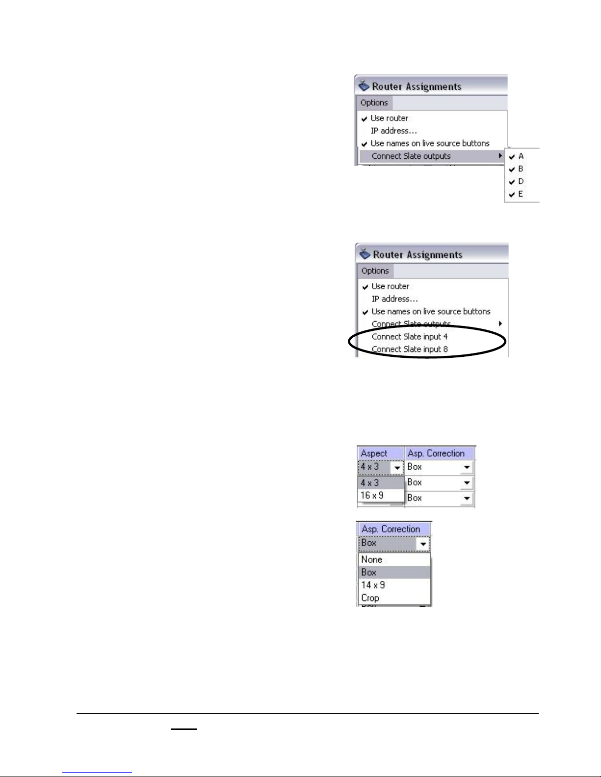
7. You may exchange up to 4 outputs (A, B, D
and/or E) for 4 more inputs.
Under the Options menu, select Connect
Slate outputs, as shown, and deselect the
unused outputs in the submenu
that appears.
Note: This is not recommended if fail-safe is
desired.
8.! If a DVI I/O card is installed, you may
exchange input 4 and/or 8 from the Slate HDSDI input card.
Under the Options menu, deselect Connect
Slate input 4 and/or Connect Slate input 8.
Once deselected, you may activate those
inputs in the Slate I/O Assignments window,
see section 1.5.
9. If you are combining 16x9 and 4x3 sources,
then you may want to treat the aspect ratio for
each input. Under the Aspect column select
either 4x3 or 16x9.
Then under the Correction column select the
treatment to be applied for each source, either
None, Box, 14x9, or Crop.
For more information about AutoAspect see
section 1.5.1.
Broadcast Pix V7.0
install - concepts - PixMaster - switcher - CG - clips - controls - team - appendix
1.7.8
Page 58

10. Under the red Router outputs section, select
which inputs you wish to route to each Aux
output, under the Route to Input column.
Select the drop down menu and select which
input you wish to route.
For more information about Aux control see
section 4.9.3.
Note: The last 8 outputs will always be grayed
out, since they connect to the Slate cards in
the workstation.
11. When all the Router Assignments are
configured, select the OK button to save and
exit the Router Assignments window.
Broadcast Pix V7.0
install - concepts - PixMaster - switcher - CG - clips - controls - team - appendix
1.7.8
Page 59

1.8 Running a Show
Broadcast Pix has a concept of shows, which contain custom
settings and specific content for each of your own productions. To
run the switcher a show file needs to be running from the Broadcast
Pix Switcher application. To create or modify a show see section 3
of this manual, which talks about PixMaster.
A show can be set to auto-load when Switcher application is started
and the Switcher application can be set to auto-start when the
workstation is turned on. When the system comes from the factory
the application is set to auto-start and the ‘Slate Sample NTSC or
PAL’ show is set to auto-load. A show is running when the
Multi-View is filled with content, as shown below.
To run a Show (when the Sample Show is set to auto-load):
1.! Double-click on the Broadcast Pix Switcher application on the desktop, and
it will open and display the Multi-View for the sample show, and then the
control panel will fill in its PixButtons for the sample show.
Broadcast Pix V7.0
install - concepts - PixMaster - switcher - CG - clips - controls - team - appendix
1.8
Page 60

1.9 The Sample Show
The sample show ships from the factory and has basic content for you to test your
system. It is recommended for you to keep this show as a back-up show, since your
show file may get corrupted. You may create a copy of the sample show to modify by
using PixMaster, see section 3.
The sample show comes up with the direct sources shown below. The first four buttons
are the first four sources attached to the iBoB or your Slate input card. The next 5 are
internal sources.
1 2 3 4 5 6 7 8 9
10 11 12 13 14 15 16 17 18
Sources 1-9 are your “Direct Sources” and include:
Source Live External Inputs
1 Whatever is attached to input 1*
2! Whatever is attached to input 2*
3! Whatever is attached to input 3*
4! Whatever is attached to input 4*
Source Internal Inputs
5.! Clip Store channel 1
6.! Clip Store channel 2 (optional)
7.! Still Store channel 1
8.! CG channel 1
9.! Logo channel 1
Sources 10-18 are your “Shifted Sources” and include:
Source Live Inputs
10.! Whatever is attached to input 5*
11.! Whatever is attached to input 6*
12.! Whatever is attached to input 7*
13.! Whatever is attached to input 8*
Source Internal Inputs
14.! Blank /No Source
15.! Blank/No Source
16. CG channel 2
17. Stills channel 2
18. Internal Black
* Input number is on Slate boards for Slate 100 and 1000, and on iBoB for Slate 2100 and
router on Slate 3000
Broadcast Pix V7.0
install - concepts - PixMaster - switcher - CG - clips - controls - team - appendix
1.9
Page 61

1.9.1 Internal Content for Sample Show NTSC
CG (ch 1)
BPix Tag.TGA
guest temp.ICG
Thank You!_1.tga (Crawl)
icg editing.ICG
CG Device.TGA
Still Device.TGA
Logo Device.TGA
Clip Device.TGA
box locator.ICG
BPix Bug.TGA
Clips (ch 1)
Auto Aspect.bpv (Native 16x9)
News Reader OTS.unc (w/ Audio)
Sarah Weather.unc (w/ Audio)
Las Vegas 16x9.bpv (Native 16x9)
Troup Color.unc (w/ Audio)
Standard Wall.bpv
Wide 2 Box.bpv
Virtual Set.bpa
BP Logo Spin.bpa (w/ Key)
01 Lens Flare Swipe.bpa (w/ Key & Audio)
02 Light Swipe.bpa (w/ Key & Audio)
CG (ch 2)
BPix Tag.TGA
guest temp.ICG
Thank You!_1.tga (Crawl)
icg editing.ICG
CG Device.TGA
Still Device.TGA
Logo Device.TGA
Clip Device.TGA
box locator.ICG
BPix Bug.TGA
Clips (ch 2)
Auto Aspect.bpv (Native 16x9)
News Reader OTS.unc (w/ Audio)
Sarah Weather.unc (w/ Audio)
Las Vegas 16x9.bpv (Native 16x9)
Troup Color.unc (w/ Audio)
Standard Wall.bpv
Wide 2 Box.bpv
Virtual Set.bpa
BP Logo Spin.bpa (w/ Key)
01 Lens Flare Swipe.bpa (w/ Key & Audio)
02 Light Swipe.bpa (w/ Key & Audio)
Stills (ch 1)
Color Bars.TGA
transmission starts.ICG
Black.JPG
Gradient.JPG
BPix Fullpage.TGA
Dual Box.bmp
dual box tag.ICG
weather map.bmp
Logo (ch 1)
BPix Bug.TGA
Box Left.TGA
Box Right.TGA
Slate 100.TGA
Slate 1000.TGA
Slate 2100.TGA
Rough Box R.TGA
Royal Box R.TGA
Viva Box R.TGA
Stills (ch 2)
Color Bars.TGA
transmission starts.ICG
Black.JPG
Gradient.JPG
BPix Fullpage.TGA
Dual Box.bmp
dual box tag.ICG
weather map.bmp
Broadcast Pix V7.0
install - concepts - PixMaster - switcher - CG - clips - controls - team - appendix
1.9.1
Page 62

1.9.2 Testing the System
If you are running the system for the first time the
sample show can help you insure everything is
operational. All of the sources should be reachable
on the Multi-View and from the panel’s program and
preview rows. The still store provides color bars, and
some of the memories help quickly check out the
keyers, CG and other parts.
1.8.3 The Sample Show Memories
Some memories are provided in the sample show,
as shown at the right. Unlike the clips and graphics
in the sample show that are disposable, you may
enjoy using memories like these in your
productions.
Mem Name Contents
951 Start or Home A known, neutral point which:
- Assigns: Key 1=CG, Key 2=Still, Key 3=Logo
- Loads the first content element of each device
- Resets the keyers, no: DVE, chromakey
957! Chromakey on Key 1 Clip 1 of person in front of a green screen
chromakeyed with Key 1 over a map on stills 1.
954! Dual Box Two DVE boxes: key 1=Cam 1, key 2= Cam 2
key3= CG 1 with a crawling title and
background=Clip 1 with an animation.
Setup in preview and needs to be transitioned
to program.
954 Key 1 Full Screen Key 1 full screen with a basic DVE move.
955 Key 2 Full Screen Key 2 is full screen with a basic DVE move.
You can customize any of these, or add your own, see section 4.10
Broadcast Pix V7.0
install - concepts - PixMaster - switcher - CG - clips - controls - team - appendix
1.9.2
Page 63

1.10 Troubleshooting
The Multi-View always displays a status light in the top left corner. If it is green all is
OK, if not (Red) select the Status Tab in the lower left corner of the Multi-View and the
following detailed status window will appear.
Lights during normal operation
Status on Slate 100 and Slate 1000
Status of Light Indicates
Slate genlock Green Slate board has reference
Orange In process of locking to reference
Red Slate has no reference
Panel ready Green Control panel is ready and has joined show
- (Grey) It is not
Status message Computer message on what is currently happening
Broadcast Pix V7.0
install - concepts - PixMaster - switcher - CG - clips - controls - team - appendix
1.10
Page 64
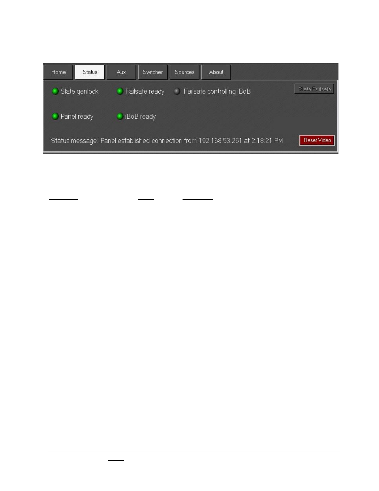
Status on Slate 2100
Lights during normal operation
Status of Light Indicates
Slate genlock Green Slate board has reference
Orange In process of locking to reference
Red Slate has no reference
Panel ready Green Control panel is ready
- (Grey) It is not
Failsafe ready Green Serial communication from panel to iBoB is OK
- (Grey) It is not
iBoB Ready Green Ethernet communication to iBoB is OK
- (Grey) It is not
Failsafe controlling iBoB - (Grey) In normal mode (control via Ethernet)
Green In Fail-safe mode (control via Serial)
Status message Computer message on what is currently happening
Reset Video Will reset the sources/video on iBoB
Caution: will cause all video to flash on program/air
Broadcast Pix V7.0
install - concepts - PixMaster - switcher - CG - clips - controls - team - appendix
1.10
Page 65
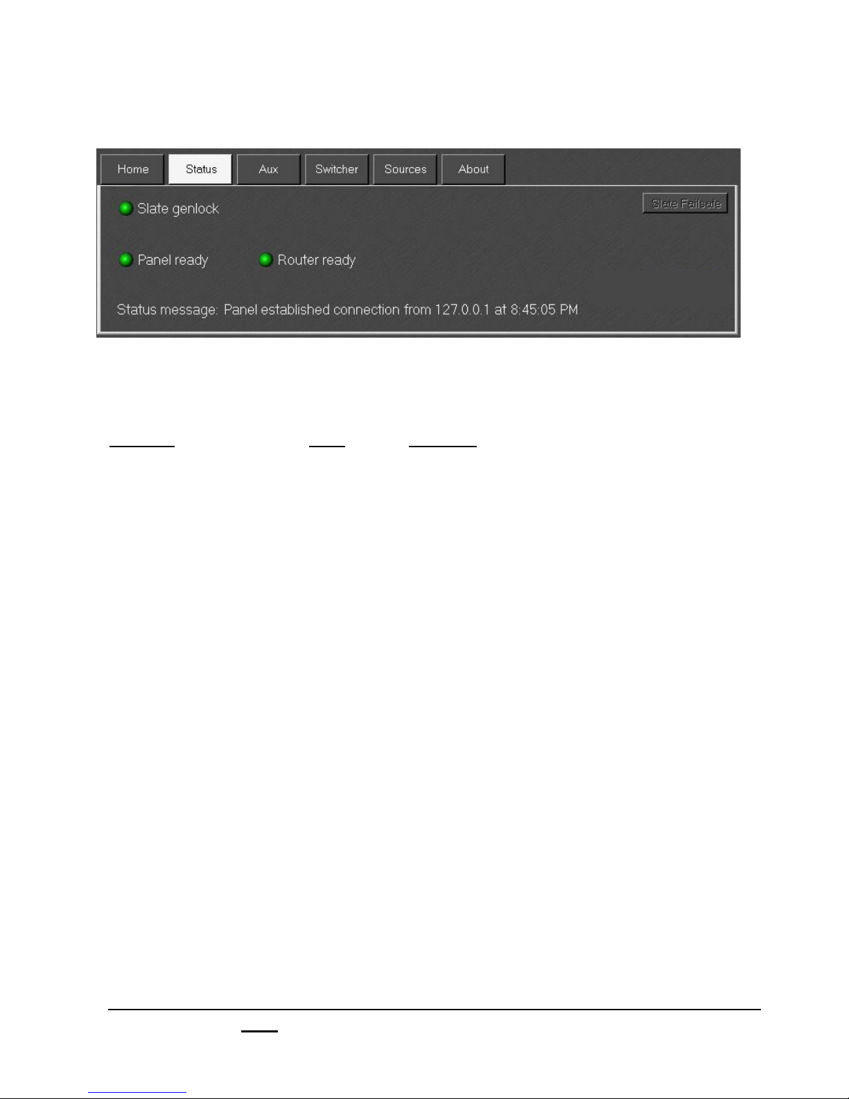
Status on Slate 3000
Lights during normal operation
Status of Light Indicates
Slate genlock Green Slate board has reference
Orange In process of locking to reference
Red Slate has no reference
Panel ready Green Control panel is ready
- (Grey) It is not
Router Ready Green Ethernet communication to Router is OK
- (Grey) It is not
Status message Computer message on what is currently happening
Broadcast Pix V7.0
install - concepts - PixMaster - switcher - CG - clips - controls - team - appendix
1.10
Page 66

1.11 Input Timing & Asynchronous Sources
Reference
The Broadcast Pix Switcher requires a reference input from an analog black burst
sync generator.
Format
Internally, the Broadcast Pix uses the SDI format (SMPTE 259M), and all systems
provide SD-SDI digital video I/O with embedded audio (SMPTE 272M ).
In addition, Slate can accept HD/SD-SDI formats SMPTE 296M, SMPTE 274M, ITU-R
BT601-5, SMPTE 259M and SMPTE 292M.
Slate also has analog video I/O conversion for composite, Y/C and component, and its
clip store has embedded audio as well as analog stereo audio.
Synchronous Inputs
All systems work well with all video inputs that accept a ref input for gen-lock,
including broadcast cameras, tape recorders, servers, etc. The delay through the
Slate system on synchronous sources is 1 frame, even if the image is inside a DVE
box (picture in picture).
Asynchronous Inputs
With a precaution, the system will also accept and self time asynchronous sources,
such as a DVD player. The precaution is to preview each asynchronous source
before taking it to air, which gives the systems the few frames it needs to settle the
source down. Unlike synchronous sources, these should not be taken directly to air,
because the settling is then visible on program. All direct Slate live Inputs accept
asynchronous inputs, and on the inputs coming from the iBoB, inputs 1 through 6
accept asynchronous sources. The delay through the Slate system on asynchronous
sources is 2 frames.
HD Inputs
The HD I/O card accepts both SD and HD video signals and processes all video at
486p/576p. Although the HD card can accept both Synchronous and Asynchronous
sources, it is advised to use genlocked sources to reduce the amount of the delay in
the system. In addition to the above delay, there is 1 frame of delay to scale the video
coming in and 1 more frame of delay to scale video going out. A complete genlocked
system will have a total of 3 frames of delay, a complete non genlocked system will
have a total of 4 frames of delay. In ‘Presentation Mode’, where all video is being
processed progressively, the total amount of delay is 1.7 frames.
See the next page for a complete listing of possible delay.
Broadcast Pix V7.0
install - concepts - PixMaster - switcher - CG - clips - controls - team - appendix
1.11
Page 67

1.11.1 System Delay
Below is a grid of the maximum total system delay in milliseconds, depending on
which formats are used. Usually delay can be compensated in a studio environment
with an audio delay, In image magnification (IMAG) productions, it is important to have
the least amount of delay possible.
SD-SDI or HD/SD HD/SD HD
Analog SDI Card SDI Card Presentation
In & Out In & Out In or Out* Mode**
NTSC
Synchronous/Timed Sources
NTSC
Asynchronous/Untimed Sources
PAL
Synchronous/Timed Sources
PAL
Asynchronous/Untimed Sources
33 ms 99 ms 66 ms 67 ms
66 ms 132 ms 99 ms N/A
40 ms 120 ms 80 ms 80 ms
80 ms 160 ms 120 ms N/A
* If you’re only using the HD I/O card for input only, and
using Output A, B or C on the Slate Switcher Card there is
no added delay on the output side. The same is true if
you’re using the HD I/O card for HD up-conversion, and
only using a SD-SDI or Analog card for input with no HD
signals.
Broadcast Pix V7.0
install - concepts - PixMaster - switcher - CG - clips - controls - team - appendix
** Presentation Mode is using only 720p genlocked
cameras coming in and going out 720p to a progressive
projector.
1.11.1
Page 68

1.12 Changing What Show is Running
In BPswitcher, click on File and a drop down menu will
appear, then select Load Show, and a window will appear
with the various saved shows. Select the one you want.
1.13 Settings
1.13.1 Changing the Startup Show
When the system ships from the factory it is set to load the sample show. You can turn
off auto-loading, or after you create more shows, you can change the system to auto-
load a different show. If you turn off auto-loading, then Broadcast Pix Switcher will still
open, but you need to then Load Show as described above.
To change which show auto-loads:
1.! In BPswitcher, click on Setup and a drop
down window will appear, then select
Startup and then Show… as shown to
the right. Click it to open the Startup
show preferences window, as shown
below.
2.! Select the show you want to auto-load,
such as Sample Show NTSC in this
example.
3.! Click OK.
To have no show auto-load on startup:
1.! Uncheck the box labeled Load Show at
Startup.
2.! Click OK.
Broadcast Pix V7.0
install - concepts - PixMaster - switcher - CG - clips - controls - team - appendix
1.12
Page 69
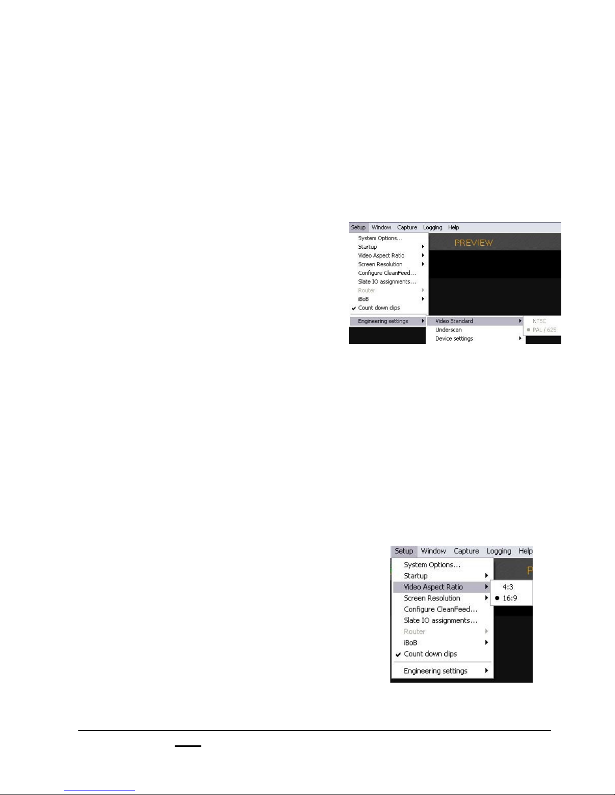
1.13.2 Selecting between NTSC/525 and PAL/625 Formats
Systems generally come from the factory set up for the local standard of the country,
such as NTSC in most of the Americas and Japan and PAL/625 in Europe and other
countries. NTSC uses a pixel size of 720x486, with 525 lines and 30 (29.97) frames
per second. PAL uses a pixel size of 720x576, with 625 lines and 25 frames per
second.
To change between NTSC to PAL:
1.! Make sure a show is not running, then in
BPswitcher, click on the Setup menu.
2.! From the drop down window select
Engineering settings.
3.! From the next drop down window
select NTSC or PAL/625.
4.! If the iBoB is powered select Reset Video
in the Status Tab on the Multi-View, or
unplug the iBoB or Router and plug it in again.
5.! Restart the BPswitcher application.
1.13.3 Selecting 4:3 or 16:9 Aspect Ratios
The Broadcast Pix Slate system can switch between 4:3 and 16:9 shows easily,
without the need of a restart. All outputs are a pixel for pixel (or 1:1) output and rely
on the output device (like a monitor, projector or VTR) to apply any letterboxing. If a
HD card is installed the HD output may compensate in place of the output device,
see the next section regarding Dual Aspect.
To change the show’s Aspect Ratio:
1.! Click on the Setup menu.
2.! From the drop down menu select
Video Aspect Ratio.
3.! Select the desired aspect ratio by selecting
either 4:3 or 16:9. The “dot” will move
to the selection.
Note: When the Video Aspect Ratio changes, so to does the Multi-View to compensate for the source
monitors. You may need to create multiple layouts, some for 4:3 shows and others for 16:9 shows.
See section 2.5.9.
Broadcast Pix V7.0
install - concepts - PixMaster - switcher - CG - clips - controls - team - appendix
1.13.2
Page 70
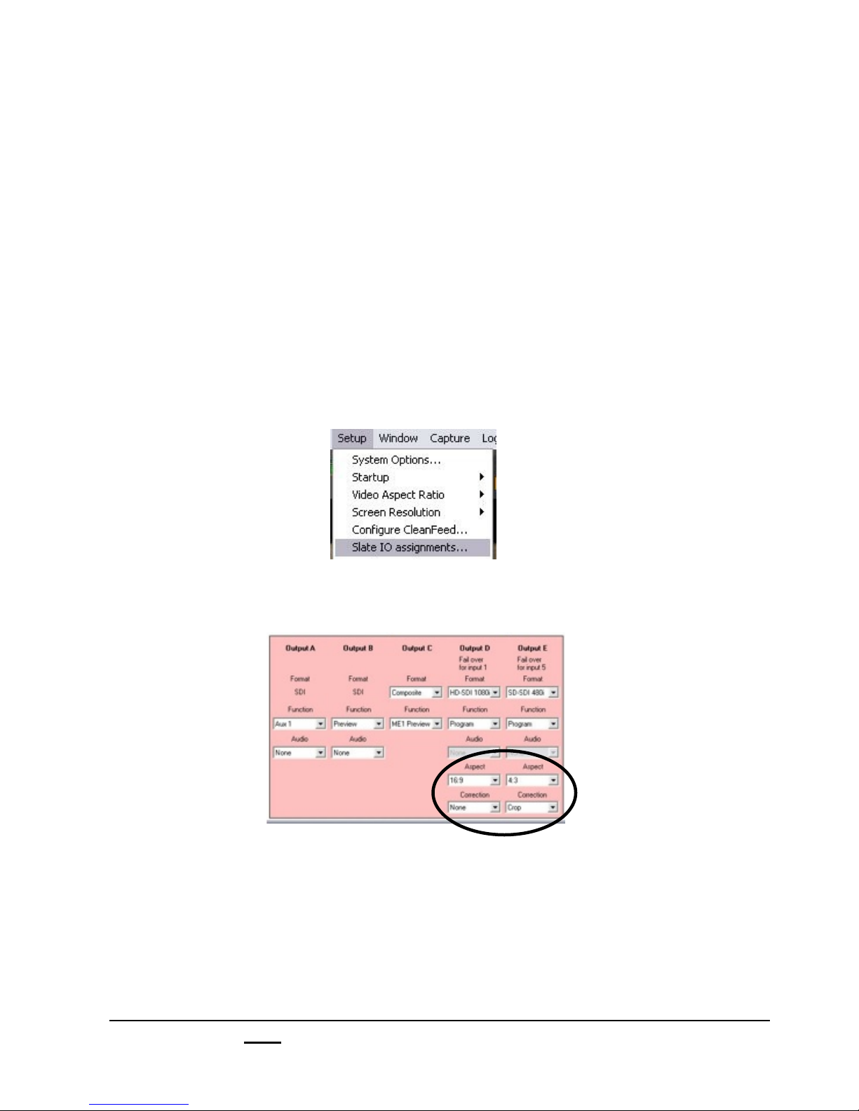
1.14 DualAspect
As described in section 1.4.1 Broadcast Pix Slate switchers come standard with
selectable 4:3 or 16:9 video aspect ratios. On HD Slate systems with 2 HD cards,
Broadcast Pix can output both 4:3 and 16:9 video aspects simultaneously. This is ideal
when you need to simulcast to two different mediums, i.e. TV broadcast and Internet
or Image Magnification (IMAG) and TV broadcast.
DualAspect uses both output D and output E on HD systems. You can select your
output in the Slate IO Assignments menu, as described below. Be sure to add an
aspect treatment to each input as well to each content element to ensure proper
output, as described in section 1.5.1.
To enable DualAspect:
1. In BPswitcher select Setup and from the drop down menu and select
Slate IO assignments…
2. Under the pink output section select the desired aspect ratios for both output D
and output E under the Aspect drop down menu, as shown, either 16:9 or 4:3.
3. Under the Correction drop down menu select the desired output treatment,
either None, Box, 14x9 or Crop. The common setting used in most applications
is Crop.
4. Click on Apply to activate your selection.
5. Click on Save to save and close the Slate IO Assignments window. You are
now outputting both a 4:3 (cropped) and a 16:9 show.
Broadcast Pix V7.0
install - concepts - PixMaster - switcher - CG - clips - controls - team - appendix
1.14
Page 71
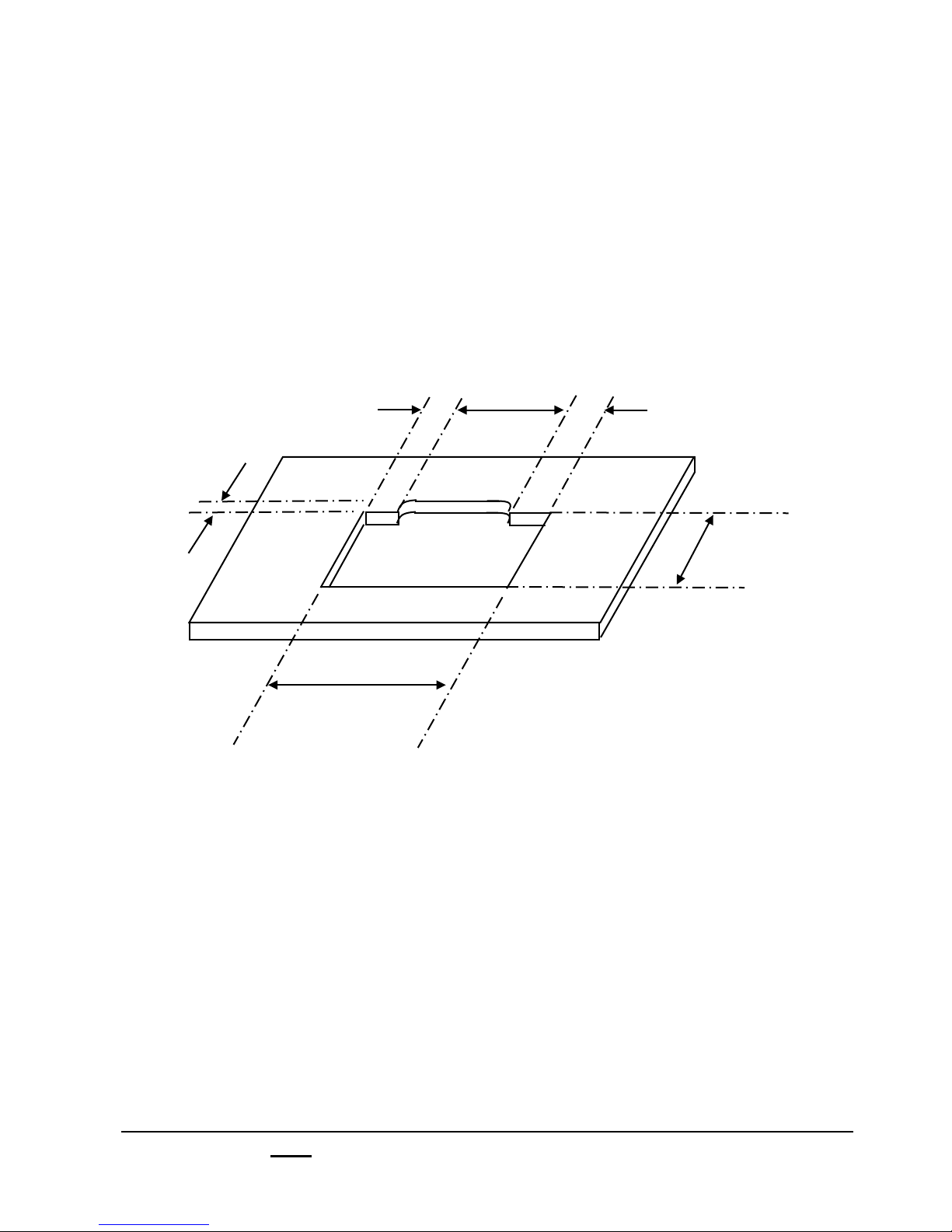
1.15 Control Panel Installation
Most Broadcast Pix control panels are used on a tabletop, which provides a better
viewing angle in most light conditions, especially to view the PixButtons. The panel
may also be recessed into a hole cut out of a table top or console. If a cut out
installation is desired, then the following dimensions should be used to cut the hole in
the console top. The panel may fit into existing cut-outs for older equipment, as it is
the same width as a GVG100 control panel.
2 inches
5.1 CM
4.25 inches
10.795 CM
17.5 inches
44.5 CM
9 inches
22.86 CM
Dimensions for Control Panel
4.25 inches
10.795 CM
11 5/8 inches
29.5 CM
Broadcast Pix V7.0
install - concepts - PixMaster - switcher - CG - clips - controls - team - appendix
1.15
Page 72

Section 2:
Broadcast Pix Concepts
2.1 Broadcast Pix Features
Integrated Broadcast Studio Contains an entire control room of devices
including: switcher, clip stores, character generator
still stores, logos, DVEs, monitoring, optional
audio, camera and external DDR control.
Pristine SDI Video Create superb digital video (SMPTE 259M)
with 3 keyers (upgradeable to 6 keyers),
background video, and a second background when
transitioning. Slate 2100 adds iBoB DSK.
Versatile Control Panel Slate 1000, 2100 and 3000 feature a fast-action
control panel enables rapid control of all sources,
devices and keys
Confidence of On-Button Content Execute with confidence, as not only the device
type, but the actual content element is displayed
on PixButtons for every source and keyer, as well
as on the Multi-View.
Personal Studio Now one person can create engaging live video
that used to require a team of operators
Grow to a Team Studio For complex production add more panels,
as described in the team section
Fail-Safe On-Air Multiple redundancies always keep your show
on-air. Redundant routing, panels and power.
Broadcast Pix V7.0
install - concepts - PixMaster - switcher - CG - clips - controls - team - appendix
2.1
Page 73
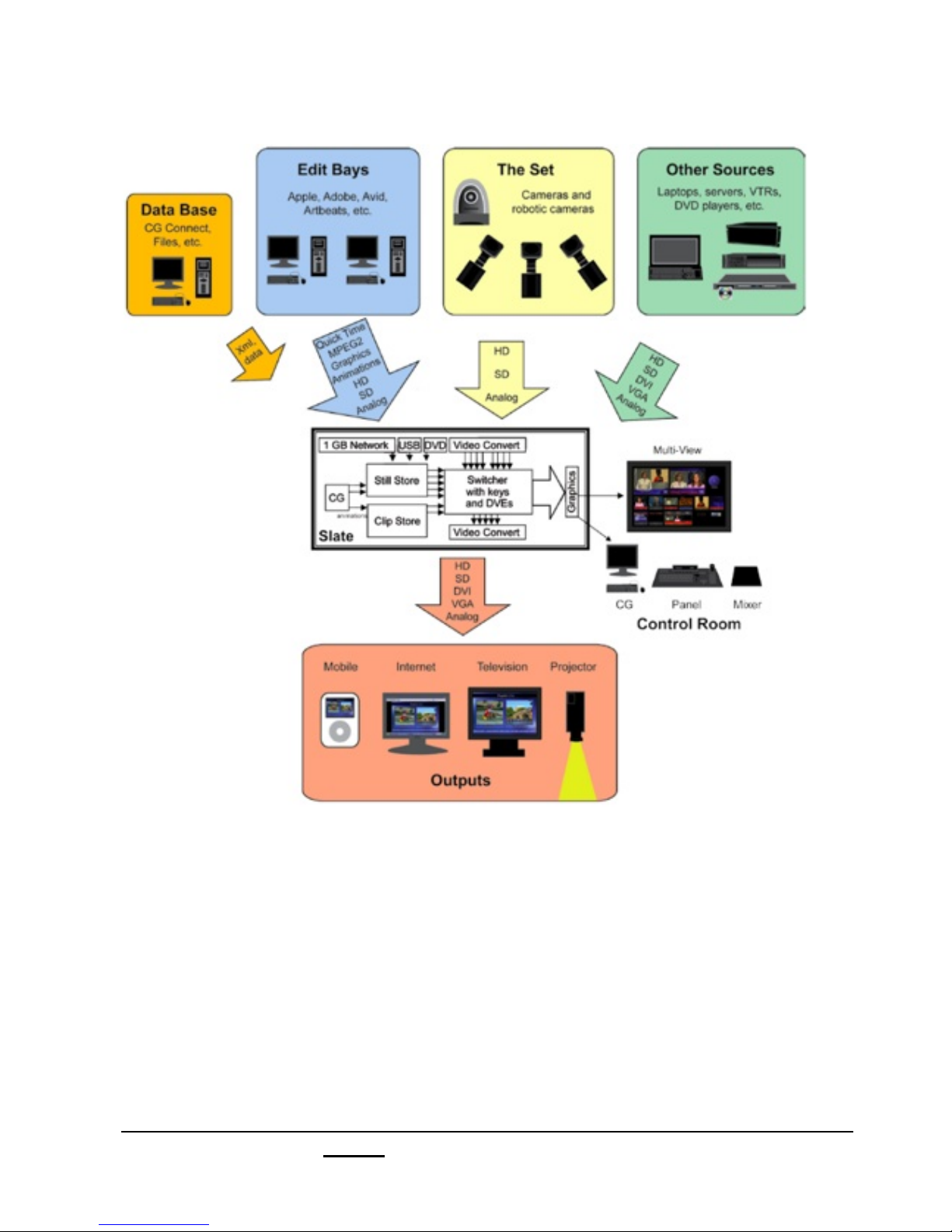
2.1.1 Video Flow Diagram
Every Broadcast Pix Slate system has an integrated Windows XP computer, which
enables the switching matrix to be extended into the computer, so it can access disk
space for clips, graphics and animations.
As shown in the above diagram, sources may come in from a wide range of creation
points. From live video of any format to video and graphic files over a network, the
Broadcast Pix Slate system improves your workflow.
Video is then processed in the Slate input video card, which enables up to 6 video
keyers with DVEs, 8 chromakeys and a wide-range of mix effects.
Sources are then monitored on the integrated Multi-View and outputs through the Slate
outputs cards in a wide range of standard and high-definition formats.
Broadcast Pix V7.0
install - concepts - PixMaster - switcher - CG - clips - controls - team - appendix
2.1.1
Page 74
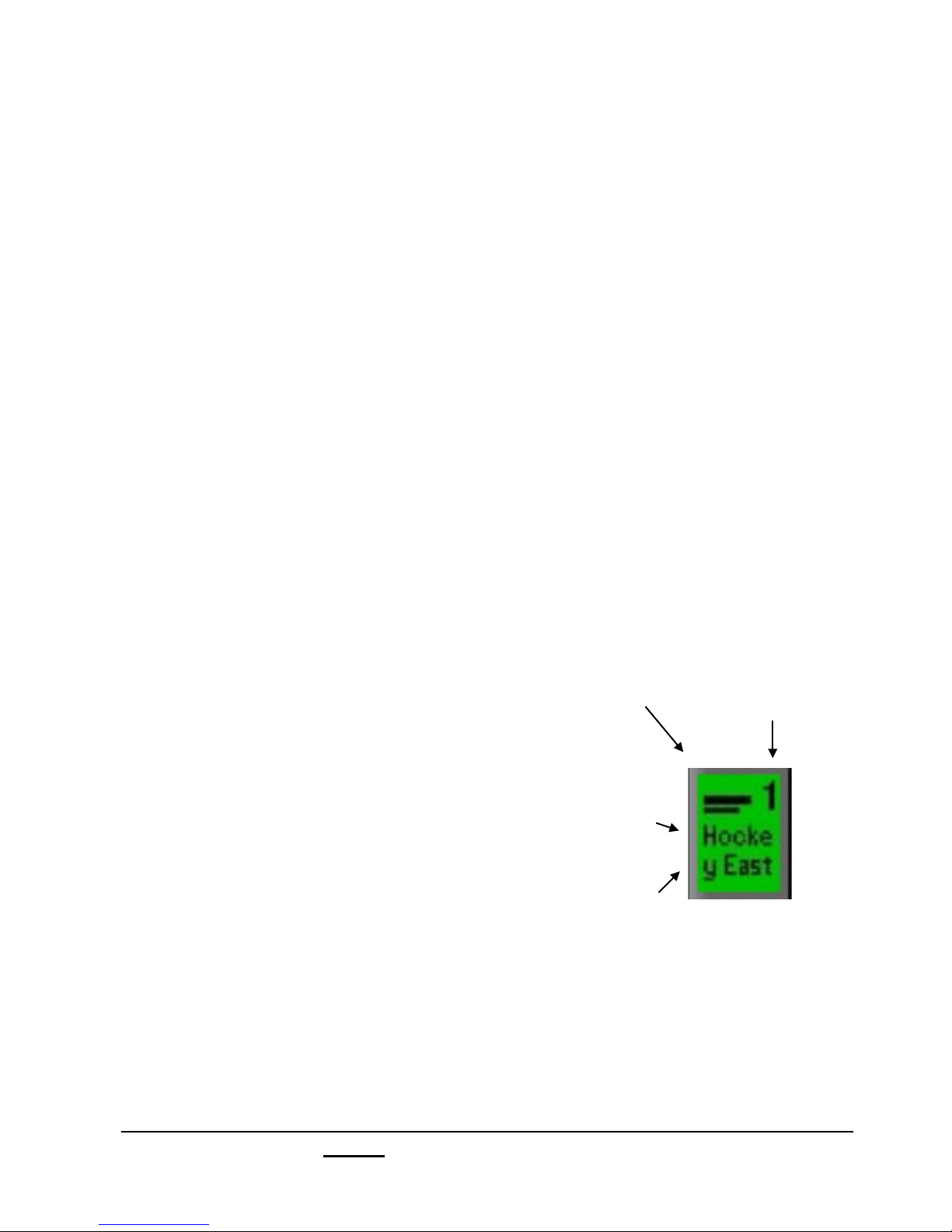
2.2 PixButtons for Executing with Confidence
Much of the versatility of the Broadcast Pix system is due to its unique picture buttons,
called PixButtons. Each has a small computer VGA display built into the button, which
has a resolution of 36x24 pixels.
PixButtons show Information at a Glance
All PixButtons on the Broadcast Pix panel show information at a glance. They all
contain a device icon in their upper portion which shows which device is currently
active in that PixButton. In the illustration below, the Character Generator (CG) is
active, as shown by the CG icon. See Section 2.3 for all icons.
The remainder of the PixButton generally shows what individual content element is
now active on this device in this PixButton. In the illustration shown below the content
number and name is shown, which are the file name and number of this content
element when it was imported into the show memory system. As an alternative, some
PixButtons use a picture to convey content, as shown on the next page.
What Device is in Here? CG
What channel of that device? 1st Channel
What is the Name of the currently Hockey
selected Content in the device? East
Tally - Is this On-Air, Selected, or Off? Green
Red On-Air
Orange Off-Air, but selected.
Green Off-Air and not selected.
PixButton
Broadcast Pix V7.0
install - concepts - PixMaster - switcher - CG - clips - controls - team - appendix
2.2
Page 75
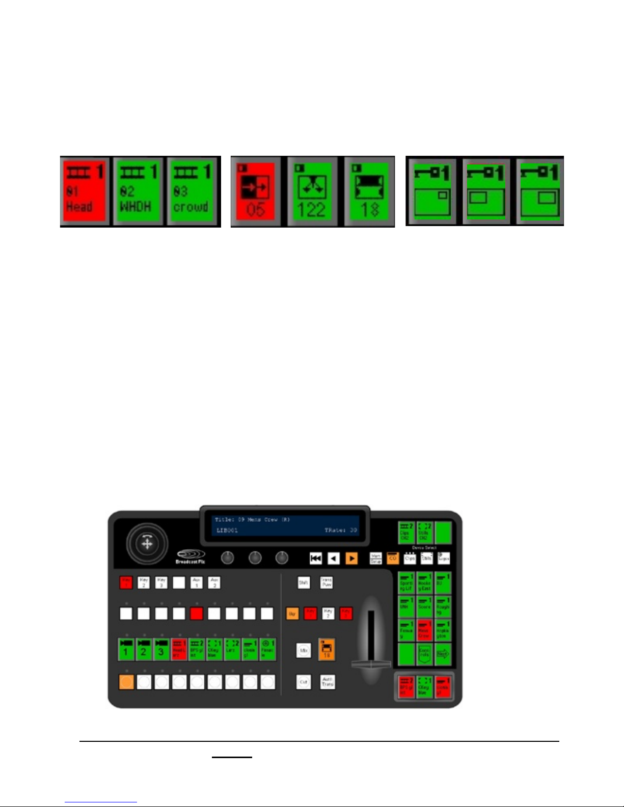
PixButtons Streamline Selection
PixButtons streamline the selection of content for all devices, such as the uses illustrated
below, plus CG, Logos, Stills, Effects or a Keyer.
Clips Effects DVE boxes
Five Kinds of PixButtons
A total of 28 PixButtons are used in 5 different areas of the Broadcast Pix control panel:
1. 12 in the PixPad To select content within a device, and for modifiers
2. 9 Sources To see what is on each source, and selection without preview
3. 3 Direct Key To see what is in each keyer, and to take it on-air or off
4. 3 Assignable Devices To see what is in each assignable device, and to select it.
5. 1 Effects PixButton To see the active effect, and to select the effects controls
Assignable Devices
“Wildcard”
PixPad
Sources
Direct Keys
Broadcast Pix V7.0
install - concepts - PixMaster - switcher - CG - clips - controls - team - appendix
Effects
2.2
Page 76
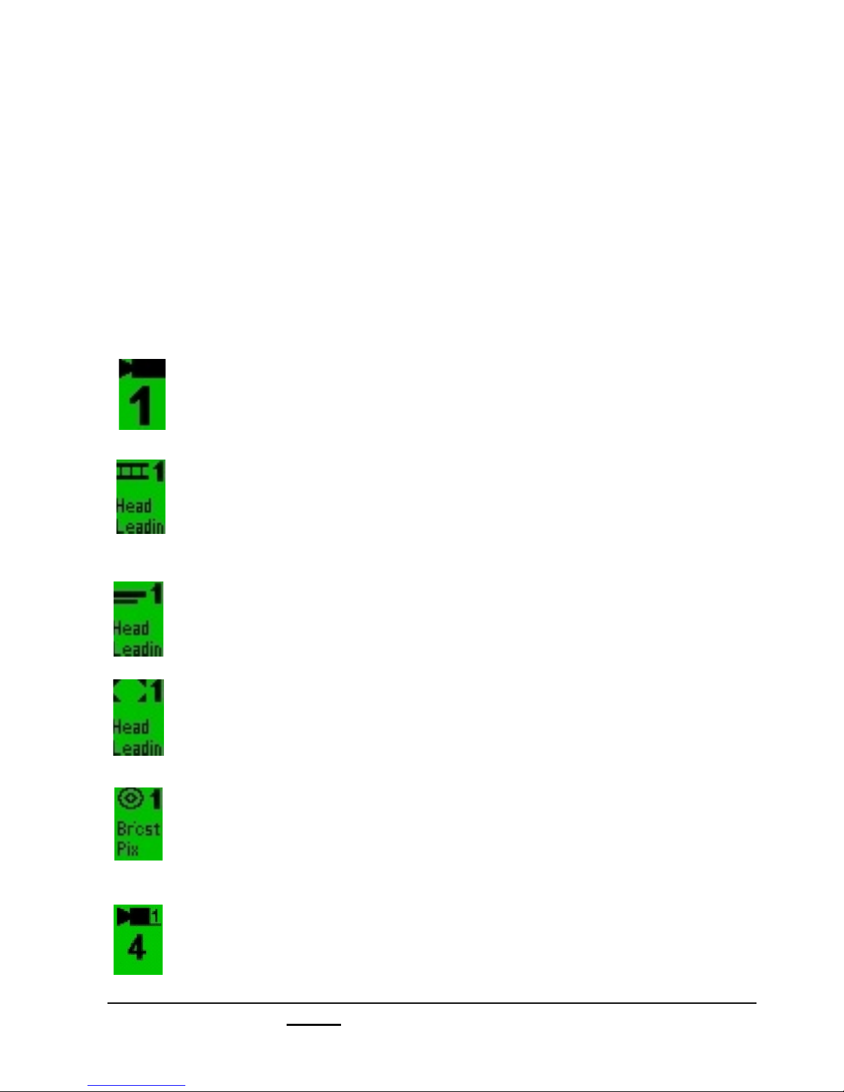
2.3 Devices
The Broadcast Pix panel can control a studio of devices. Each device performs one
function. In a traditional live television studio, many of these devices are in a separate
box with its own operator. The Broadcast Pix panel provides flexible control over a wide
range of devices, by using the device controls. When a device is selected the entire
bank of device controls are assigned to that device, including a Joystick, 3 knobs, motion
buttons, and a PixPad of 12 PixButtons. The list of supported devices will grow over
time, check for new devices at www.broadcastpix.com.
Each device has a unique icon that appears on the top of the PixButtons. Broadcast Pix
Software Version 6 supports the following devices, and use the following icons:
Switcher:
Select both external and internal input with a control panel with 9 direct access
input, and 18 with shift. Classic program/preview layout. Illustration shows
Camera 1. Other icons are used for VTR and other sources.
Clip Store: (2 channels)
Instant access to clips. Import/ingest and play-out. Use motion controls and
time codes. Plays uncompressed with embedded audio as well as compressed
clips (QuickTime/DV/MPEG). The Clip Store also plays animated graphics with
or without an alpha channel (via a 32 bit image sequence).
Harris Inscriber TitleMotion Pro Character Generator: (2 Channels)
Create broadcast quality graphics with shadows, bevels, transparencies, logos
and many more. Create your own look, or use easy templates. Add motion with
rolls, crawls and 3D animations.
Still Store: (2 Channels)
Have thousands of photos and graphics at your fingertips. Recall with a press of
a button from the corresponding library shown on the monitor.
Import many file types: .bmp, .jpg, .tga, .tiff, .gif and .png.
Logo Store:
Brand your production with a logo in its own key layer. Logo store makes it easy
to apply or remove a logo at any time. Import any logo, or create your own with
Inscriber logo creation tools.
Camera Control:
Optional camera control of Hitachi and Sony cameras with Pan & Tilt heads.
Including preset positions, tilt, pan, zoom, focus, iris and CCU controls.
Broadcast Pix V7.0
install - concepts - PixMaster - switcher - CG - clips - controls - team - appendix
2.3
Page 77
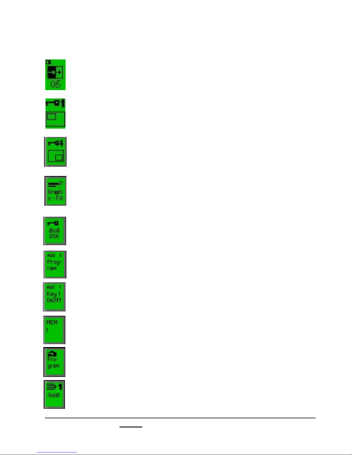
List of Devices, Continued
Effects:
Over 150 transitions. DVE transitions include push-offs and squeezes.
Wipe transitions include horizontal, circles, stars, clocks, and many more.
Keys 1-3:
Handle fine quality edging with 14-bit quality. Each Key supports a standard
DVE Box (Picture-in-Picture), sizing, cropping, border controls and
Chromakeys.
Keys 4-6:
Keys 4-6 are an option that handle fine quality edging with 14-bit quality. Each
Key supports a DVE Box (Picture-in-Picture), sizing, cropping, border controls
or optional Chromakeys.
External Key:
1 channel of external keying, when a Key Cut and a Key Fill signal is provided
from an external graphics machine. This feature uses 2 keyers (Key 3 and Key
4) and supports clip and gain adjustments, shaped and unshaped signals and
key inversion.
iBoB DSK:
External keyer in the Break-out-Box for an external character generator or
other external key sources.
Aux:
The Aux 1 and Aux 2 buttons act as Auxiliary outputs, and can be assigned to
program, preview or another internal/external source. Also used when
DualAspect option is enabled.
PowerAux:
An option to enable Keys 1-6 to be keyed onto Auxiliary outputs.
StudioMemory (MEM):
Is a device that enables snapshot recalls of the entire panel, or portions
thereof, with either just the set-up, or the set-up and source assignments.
Capture:
Enables the capture of a still image of program or preview to imported back
into the system, or exported to another application.
External Video Server Control (DDR):
An option which enables 3 channels of an external video server to be
controlled from the panel through a serial connection using the VDCP Protocol,
having its clip name appear in the PixPad. Currently 360 Systems and Harris
Nexio are supported.
Broadcast Pix V7.0
install - concepts - PixMaster - switcher - CG - clips - controls - team - appendix
2.3
Page 78

2.4 Device Controls
Device Controls is the portion of the control panel that can be assigned to whichever
device you wish to control, i.e. clips, graphics, keyers, etc. The upper half of the
panel is comprised of the device controls, as shown in the illustration below. The
remainder of the panel is comprised of the fixed controls, which are described in
section 4.
The device controls are comprised of the Joystick, 3 knobs, 3 motion buttons, a
group of 12 PixButtons called the PixPad, and a display, as shown below. When any
device is selected, all of these the controls are dedicated to it.
Device Controls portion of Panel
Display Device Select
3 Axis 3 Knobs Motion
Joystick Buttons
Broadcast Pix V7.0
install - concepts - PixMaster - switcher - CG - clips - controls - team - appendix
PixPad with
12 PixButtons
2.4
Page 79

2.4.1 Assigning the Device Controls
The entire bank of device controls can be assigned by any of 15 buttons:
7 Content Devices
The device controls are assigned to most
devices by using the four permanent
device selection buttons for CG, Clips,
Stills and Logos or three assignable
“wildcard” device selection buttons above
them, as illustrated below. In this
illustration the wildcard buttons are
assigned to a second channel of clip store,
camera control, and iBoB DSK. For specifics
on how to assign devices to these 3 wildcard
buttons, see section 3.9.3.
6 Destination Buttons:
-Three Key buttons
-One Source Controls button
Con
trols
-Two Aux buttons
1 Effects PixButton
1 Memory/Setup Button
Which Device is Assigned?
At all times you can tell what device is assigned to the Device Controls, by looking
at the upper left corner of the display, in this illustration it is the first channel of CG.
Broadcast Pix V7.0
install - concepts - PixMaster - switcher - CG - clips - controls - team - appendix
2.4.1
Page 80
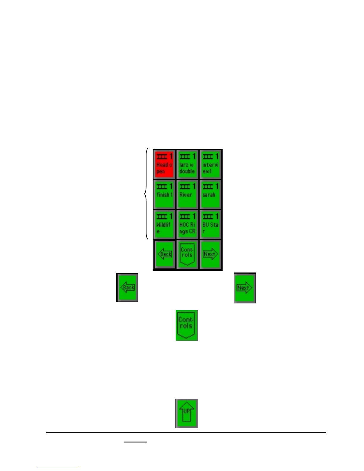
2.4.2 PixPad Navigation
The PixPad is a versatile part of the Device Controls that is used to access content
and many fast action controls. It has several navigation aids that streamline its use.
For most PixPads (other than control modifiers), the top nine PixButtons are to
select which content element, effect or memory you want. The bottom three
PixButtons are to move to the next PixPad, move back to the previous PixPad in the
library, or move down a level to either controls for the device, such as in the clip
store shown below, or to the numeric keypad such as in the Still Store.
9 Content
Selection
Buttons
To move back
to previous
PixPad
To move down
to the clip controls
To move ahead
to the next
PixPad
PixPad
To quickly jump to the first page of the content in the PixPad, simply select the device
button you are using in the Device Control section of the control panel.
When you switch to another device, like CG, and then return, the PixPad will return to
the page it was last on.
There is also an up button, to move up from control PixPads, to a previous PixPad.
Broadcast Pix V7.0
install - concepts - PixMaster - switcher - CG - clips - controls - team - appendix
2.4.2
Page 81

2.4.3 Multi-View PixPad
In the upper right corner of the Multi-View is a PixPad of thumbnails which correspond
to the active PixPad on the control panel, called the Panel PixPad. As the panel
changes its PixPad to a content device, the Multi-View displays the thumbnails
associated with the device. Content devices are Clips, Stills, CG and Logos. In the
illustration below, the PixPad is set to CG1.
The thumbnails make it easy to select any content element at the press of a button.
When selected, the Panel PixPad tallies red if on-air and orange if not, the PixPad on
the control panel will always tally red, no matter if the content is on or off air, use the
Multi-View to check tally status. If a device has more than 9 content elements, the next
page of elements can be reached from the control panel by pressing the [Next] button
on the control panel PixPad, or by clicking on the buttons in the lower right hand
corner of the Multi-View PixPad.
Device: CG1, first page in library
Panel
Panel PixPad
on Multi-View
NOTE: The Panel PixPad will always update with the control panel PixPad, no matter if Panels are
locked or unlocked.
Broadcast Pix V7.0
install - concepts - PixMaster - switcher - CG - clips - controls - team - appendix
PixPad
on control panel
2.4.3
Page 82
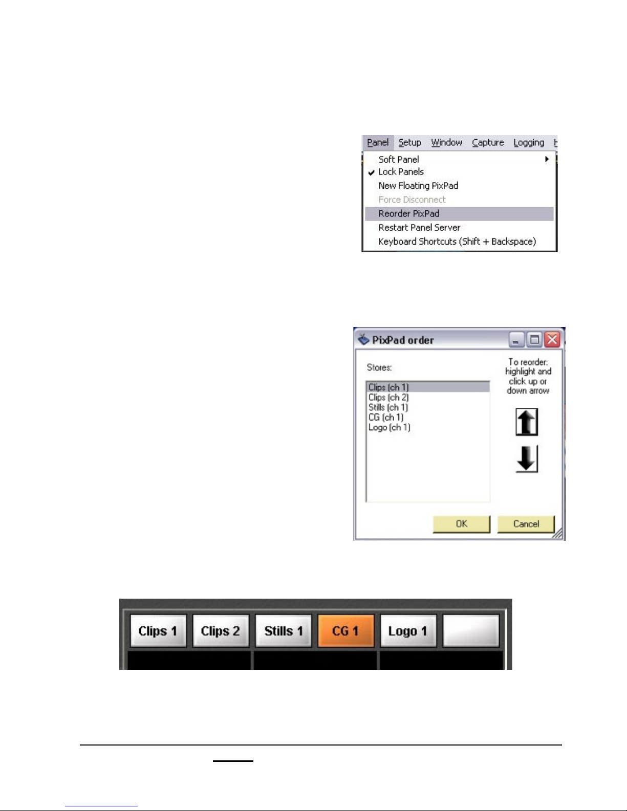
2.4.4 PixPad Order Controls
To change the order in which the PixPad tabs appear across the top of the PixPad:
1.! On the Panel drop down menu select
Reorder PixPad, and the PixPad order
window will appear.
2.! Use the up and down arrows to move the
highlighted selection to where on the list
you want it to appear. Highlight other items
and them move them with arrows as for
the first item.
3. Click OK.
Now the order will appear as you prepared it.
Broadcast Pix V7.0
install - concepts - PixMaster - switcher - CG - clips - controls - team - appendix
2.4.4
Page 83
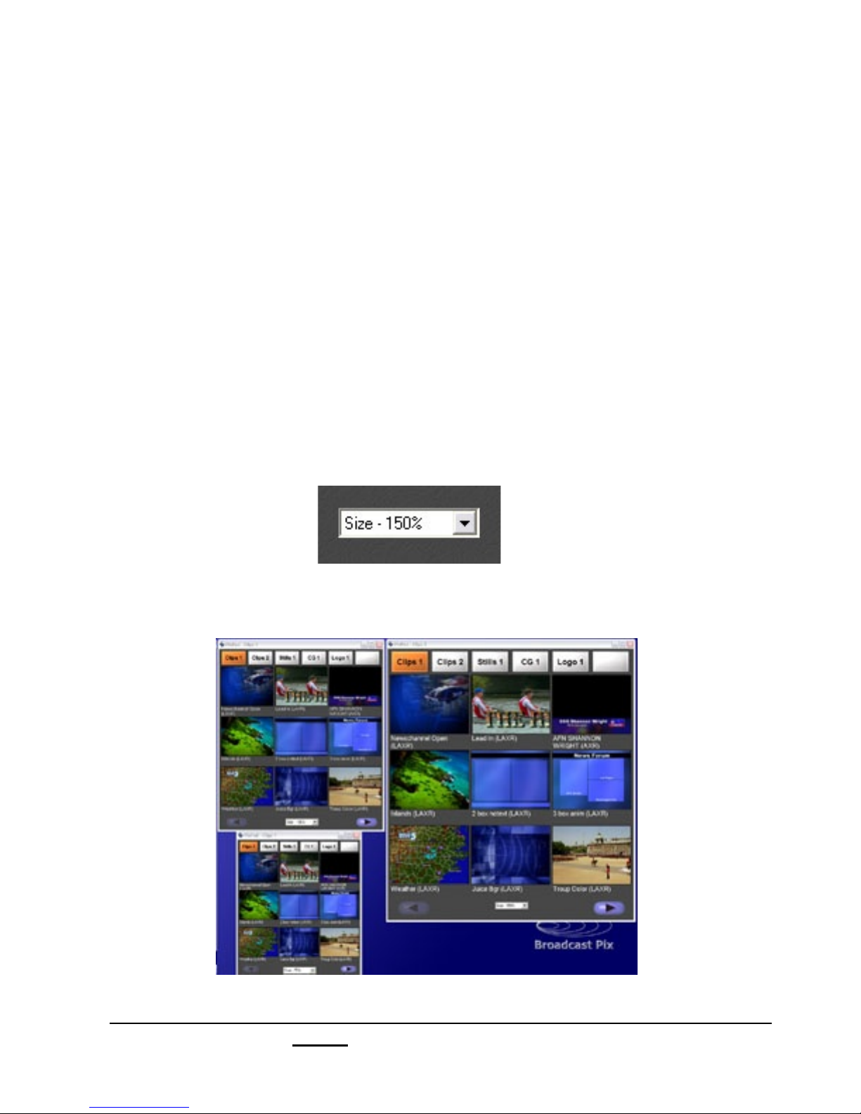
2.4.5 Floating PixPads
In addition to the Panel PixPad in the top right corner of the Multi-View, you can create
additional floating PixPads. These can be used on another portion of a large screen,
or on dual monitor systems can be opened on a the second monitor where they are
helpful as either additional info for a solo operator, or dedicated info for a graphics
operator. These Floating PixPads do not change when the control panels changes, and
are meant to independent of each other.
To open a Floating PixPad:
1.! In BPswitcher click on Panel drop down menu, and click on New Floating
PixPad.
To change the size of a Floating PixPad:
1.! Click on the Size drop down menu on the floating PixPad, and select the size
you want.
The illustration below shows three sizes: 150%, 100% and 75%
Broadcast Pix V7.0
install - concepts - PixMaster - switcher - CG - clips - controls - team - appendix
2.4.5
Page 84
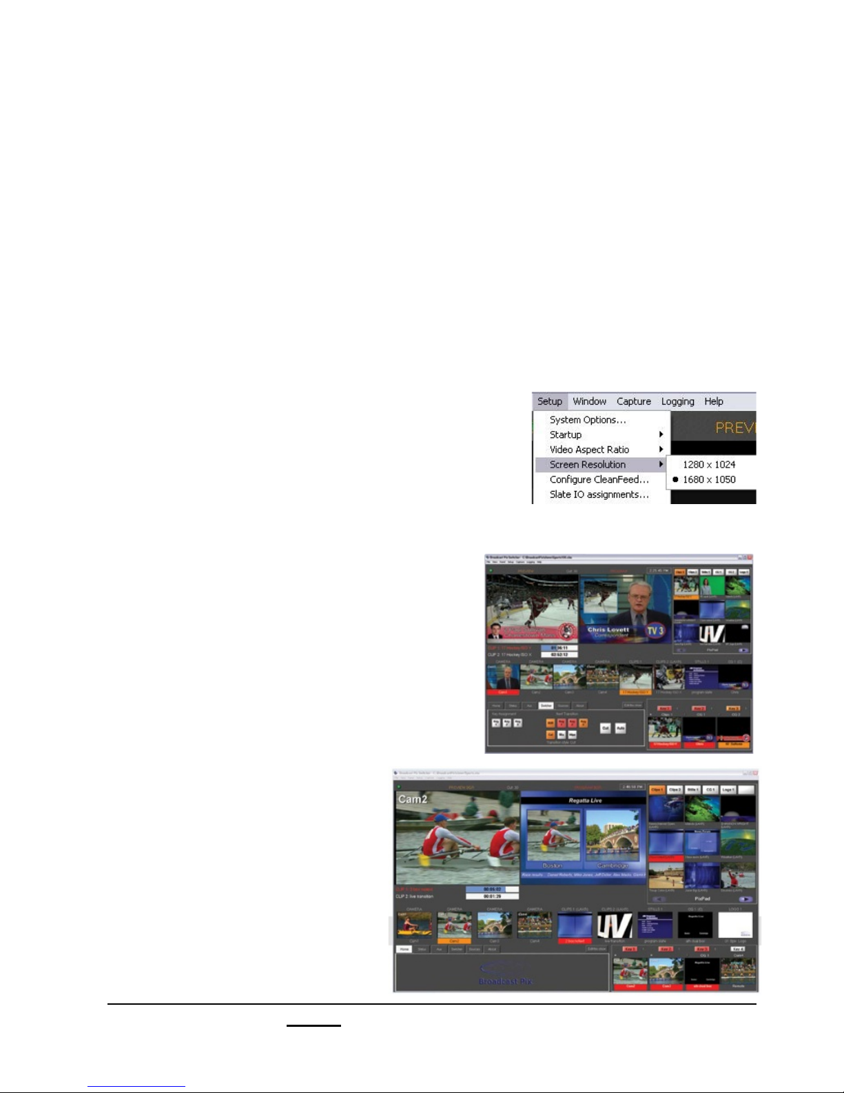
2.5 Multi-View
The Multi-View consists of source thumbnails, larger preview and program monitors,
one large PixPad of thumbnails to correspond to the control panel PixPad, keyer
thumbnails, a clock as well as tally information The Multi-View is also interactive, so
you can switch a show from the Multi-View, as a complement to using a panel, or in
place of for simple shows.
2.5.1 Monitor Sizes
The Multi-View supports 2 sizes of computer (VGA) monitors, as shown below, as well
as customizable floating windows for any size monitor, see section 2.5.9
To select Monitor Size for the main Multi-View:
1.! On the Setup menu, click on Screen Resolution,
as shown on the right.
2.! Select 1280x1024 or 1680x1050.
A restart of the application is necessary for this
setting to take effect.
Traditional Aspect Ratio Monitor
1280x1024:
for traditional 4:3 monitors,
and almost all touch screen monitors.
Widescreen Monitors
1680x1050:
for widescreen 16:9 monitors
Broadcast Pix V7.0
install - concepts - PixMaster - switcher - CG - clips - controls - team - appendix
2.5.1
Page 85

2.5.2 Overview of the Multi-View
Panels
Connected
Preview Monitor Program Monitor
Status
Indicator
Clock
Panel
PixPad
Clip Counters
Tab Window
Broadcast Pix V7.0
install - concepts - PixMaster - switcher - CG - clips - controls - team - appendix
Sources
Keyer Window
2.5.2
Page 86
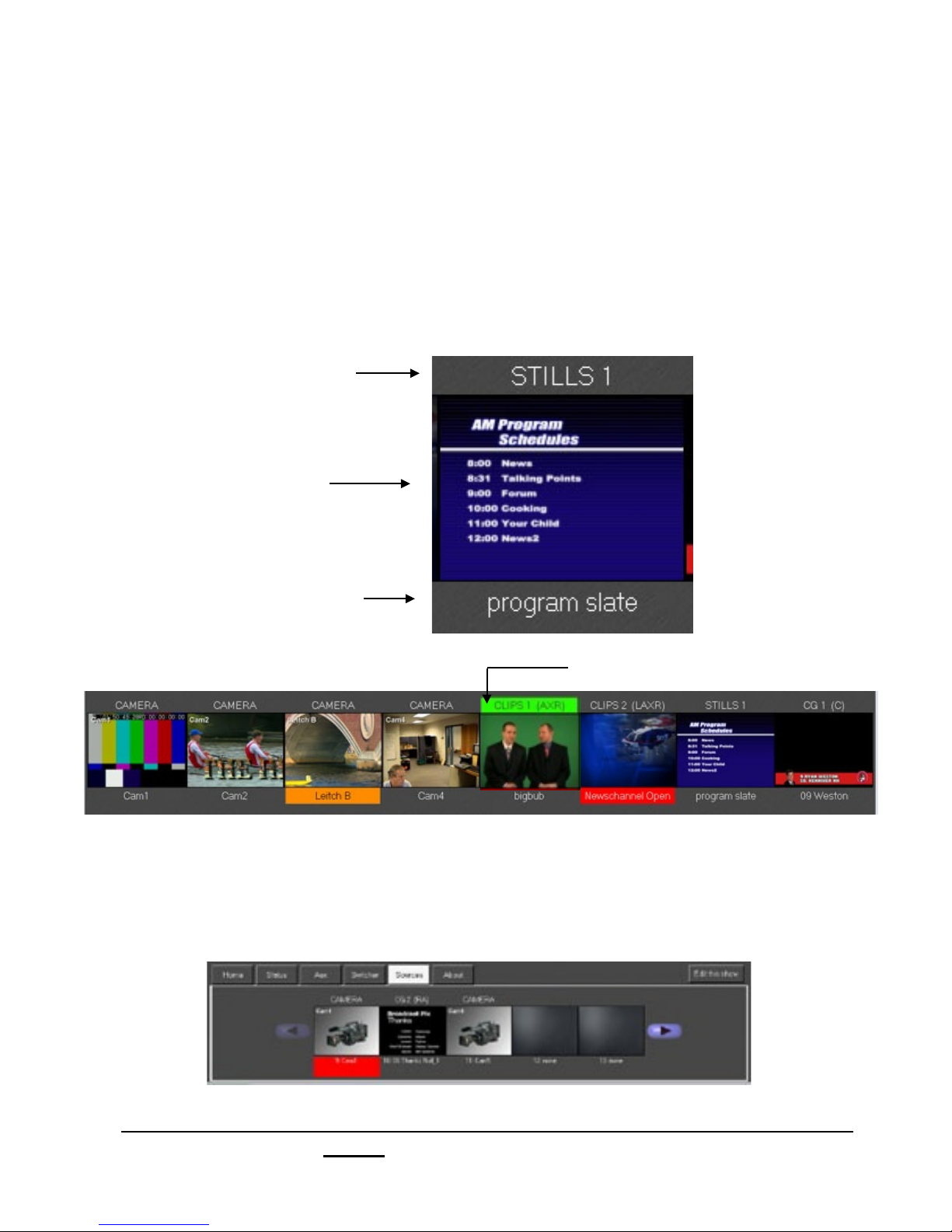
2.5.3 Sources on Multi-View
Thumbnails for the first 8 sources are displayed on 1280x1024 monitors as illustrated
below. Widescreen 1680x1050 monitors display the first 9 sources across. Thumbnails
for external sources show full motion video and thumbnails for internal devices show the
assigned content.
Each source monitor shows the following information:
Device Name
Thumbnail
Content Name
(and Tally status)
Chromakey is applied & hue of Chromakey
Tally Preview Tally Program
To view sources above the first 8 shown, click the sources tab on the Multi-View, as
shown below:
Broadcast Pix V7.0
install - concepts - PixMaster - switcher - CG - clips - controls - team - appendix
2.5.3
Page 87

2.5.4 Keyer on the Multi-View
The Multi-View shows the contents and status of 3 keyers on the bottom of the screen.
Just as with source monitors, a keyer monitor displays the thumbnail of the content that
is currently loaded into the keyer as well as the device name, content name and tally
status.
Key Transition Buttons, shows
you which keyer will be effected in
the next transition
What Device
CAMERA CAMERA
is assigned
to each
keyer
Whether the Key is:
On Program: Red (in this case)
On Preview: Orange
The name of the content
element currently selected in
the device
Not selected: Off/None
Transitioning Keys individually with the Multi-View
To Manually Bring a Key On Program:
1.! Any key that is off-air (grey or orange), can be brought on-air by clicking on
its thumbnail on the Multi-View. This will cause this key to fade on-air at the
rate for that keyer, and the tally underneath will change color to red.
To Manually Take a Key Off Program:
1. Any key that is on-air (red), can be taken off-air by by clicking on its thumbnail
on the Multi-View. This will cause this key to fade off-air at the rate for that
keyer, and the tally underneath will change color to red (or orange if its key
transition button is on).
Broadcast Pix V7.0
install - concepts - PixMaster - switcher - CG - clips - controls - team - appendix
2.5.4
Page 88

Modifiers applied to a Key are also shown on the Multi-View in the keyer window. The Key
transition rate is displayed to the right of the key transition button, and if a keyer has a
DVE or if a reposition applied to it, the indicator light to the left of the device name turns
to red from grey.
Key transition rate
Lit when DVE or Reposition is on
Broadcast Pix V7.0
install - concepts - PixMaster - switcher - CG - clips - controls - team - appendix
2.5.4
Page 89

2.5.5 Clip Store Counters
Clip counters appear on the Multi-View for each of the two channels of clip store.
They display the clip counter with both a number and a moving blue bar. They can be
set to either count up and show elapsed time (runtime), or they can be set to count
down, to show the remaining time in a clip.
Counters will move at one-second intervals, and with 10 seconds left in the clip the bar
will turn red and the counter will move at one-frame intervals.
Clip counters also provide Tally information. Red letters: On Program, Orange letters:
On Preview, White letters: Selected in the Clip Store.
To set clips to count down:
1.! In BPswitcher click on the Setup menu
and select Count down clips, a check
mark will appear as shown. Now both
counters and the counter in the display
of the control panel will be set to count
down.
(To return to show the elapsed time,
uncheck the same setting.)
NOTE: The Clip Counters bar will turn red at 10 seconds remaining only if the Clips Controls Settings are
set to not Loop, see section 6.5.4
Broadcast Pix V7.0
install - concepts - PixMaster - switcher - CG - clips - controls - team - appendix
2.5.5
Page 90

2.5.6 Basic Switching on Multi-View
The Multi-View is interactive and can be used to switch a
show instead of a panel, or as a complement to a panel
(SoftPanel or physical control panel). This can be done
with a mouse, or with a touch screen for a more tactile
interface.
Basic Moves
To change a content
selection in a key or
source
To take preview to air
Click on the PixPad
Click on the preview monitor
element desired
To change to a
different device on
the PixPad
Click on the tabs at
the top of the PixPad
To select a source
Click on the source
thumbnail and it goes to
preview*
To include a keyer in the
next transition
Click on the key button
and it will illuminate and
transition with the
To add a key to preview,
background video
or take it on/off air
(depending on key button
status)
Click on the key thumbnail
NOTE: When a source is clicked on, it goes to preview but this can be changed to make the selected
source go directly to air if desired. To change this in BPswitcher go to the Setup drop down window and
select Clicking Sources Switches, then select the desired style.
Broadcast Pix V7.0
install - concepts - PixMaster - switcher - CG - clips - controls - team - appendix
2.5.6
Page 91
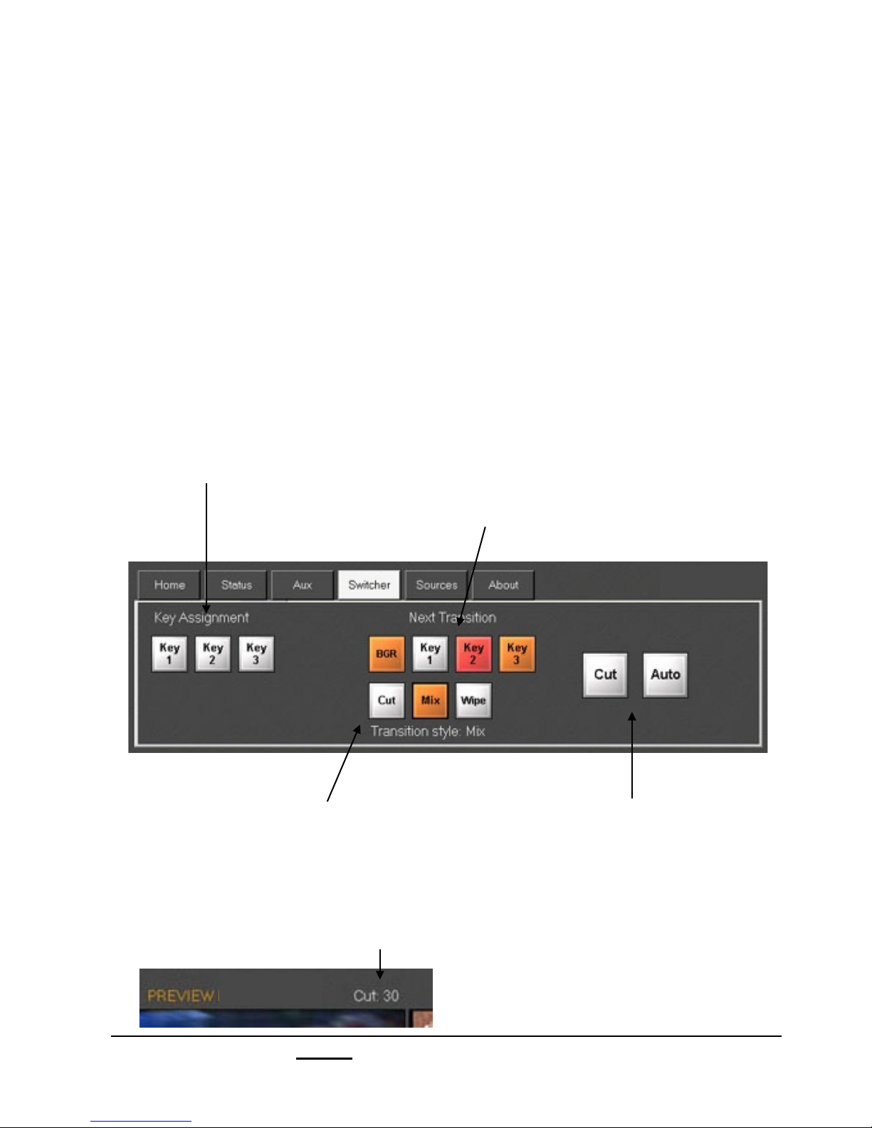
2.5.7 Advanced Switching on Multi-View
You can access even more switching capabilities on the Multi-View by setting the Tabs
Window in the lower left corner of the Multi-View to Switcher, as shown below. These
switcher controls work exactly the same as on the control panel. For more switcher
controls beyond these, open a SoftPanel or use a control panel.
To add keys or background video to the next
To assign a source to a keyer
transition
1.! Click on one of the three Key
Assignment buttons shown below
2.! Then, click on the thumbnail of the
source you wish to assign, and its key
thumbnail will change to show the new
key source.
Click on the Key or BGR buttons shown above,
and each will illuminate as you click on it and the
keyed image will be added to the preview monitor if
it is not already on air. The button illuminates red
when the key is on air, and orange when it is on
preview. (Note: the key buttons in the lower right
corner of the panel also perform the same task.)
To change the style of transition that occurs when you
click on the preview monitor
Click on Cut, Mix or Wipe. Its button will illuminate
and its word will appear over the top right corner of the
preview monitor along with the transition rate, as
shown.
Broadcast Pix V7.0
install - concepts - PixMaster - switcher - CG - clips - controls - team - appendix
To take preview to air
Either: click on the preview monitor, or,
click on cut or auto above (auto
executes whichever transition style is
selected)
2.5.7
Page 92
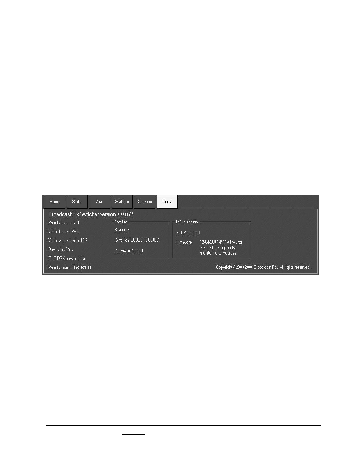
2.5.8 About Tab
The About tab in the lower left corner of the Multi-View reveals information about the
installation, including the:
Current software version installed of Broadcast Pix Switcher
Settings for NTSC/PAL and 4:3/16:9
If the iBoB is installed and the current iBoB firmware installed
Control Panel version
Slate card information
Broadcast Pix V7.0
install - concepts - PixMaster - switcher - CG - clips - controls - team - appendix
2.5.8
Page 93
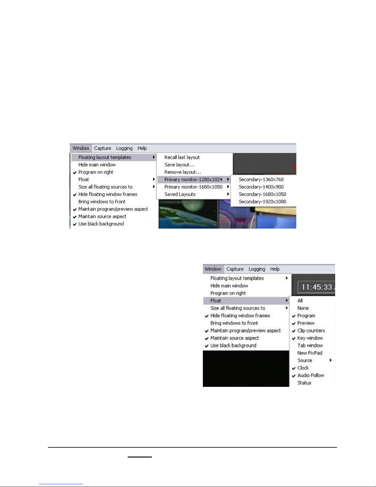
2.5.9 Floating Monitors
Most windows on the Multi-View can be floated, which serves two purposes when
working on a dual monitor system. Either create your own custom Multi-View on a large
secondary monitor of any resolution, to replace the fixed layout that is supplied, or float
selected windows for a secondary graphics or slo-mo operator. You can arrange the
windows any way you like, and then save them for later recall. So, each director/
producer or each show could have a custom layout tailored to that specific show. 8
floating window templates come installed on your system for easy recall under the
Window, Floating layout templates menu, as shown below. You may use them as a
starting point and modify/save them to your needs.
To Create a Floating Monitor Layout:
1.! In BPswitcher, click the Window
drop down menu, select Float
(as shown) and you will see the list
of windows you can float. Then
select the desired items. You may
also right-click on the source
monitors as a shortcut, to float
sources 9-18, select the Sources
Tab, and right click on the desired
sources.
2. After selecting each item, it will
appear, and then arrange it on your
primary or secondary monitor. Most
Floating Monitors can be sized by
dragging their corners.
NOTE: The native resolution of the Floating Preview/Program monitors are 320x240, where as the
Source monitors are 180x120. When resizing monitors be cautious of how large you make each monitor,
as the resolution may get distorted.
Broadcast Pix V7.0
install - concepts - PixMaster - switcher - CG - clips - controls - team - appendix
2.5.9
Page 94
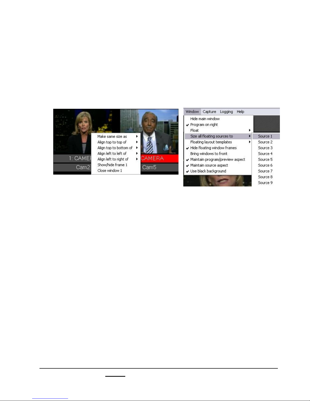
3.! To align or size floating monitors rightclick on the floating monitor and select
which source you would like to copy its
attributes from, as shown.
You may also size all the sources to
each other by selecting the Window
menu, then Size all floating source to.
4.! Once all your Floating Monitors are
placed and sized to your liking, you have
the option to not view the Windows XP
framing, for a cleaner presentation.
In the Window menu, select Hide
floating window frames.
5. To make your Floating Monitors stand
out in your display, you also have the
option to add a black background behind
the Floating Monitors.
In the Window menu, select Use black
background.
You may also use your own custom
background, simply change the
Windows XP desktop to your liking in the
Display Properties of the workstation.
6. In some scenarios it may be desired to
hide the main Multi-View and use the
only the Floating Windows. To do so in
the Window menu, select Hide Main
Window.
NOTE: To close or modify one floating monitor, right click on the window and select Show/hide frame to
activate the window frame for that one monitor or select Close window to close that monitor.
Broadcast Pix V7.0
install - concepts - PixMaster - switcher - CG - clips - controls - team - appendix
2.5.9
Page 95
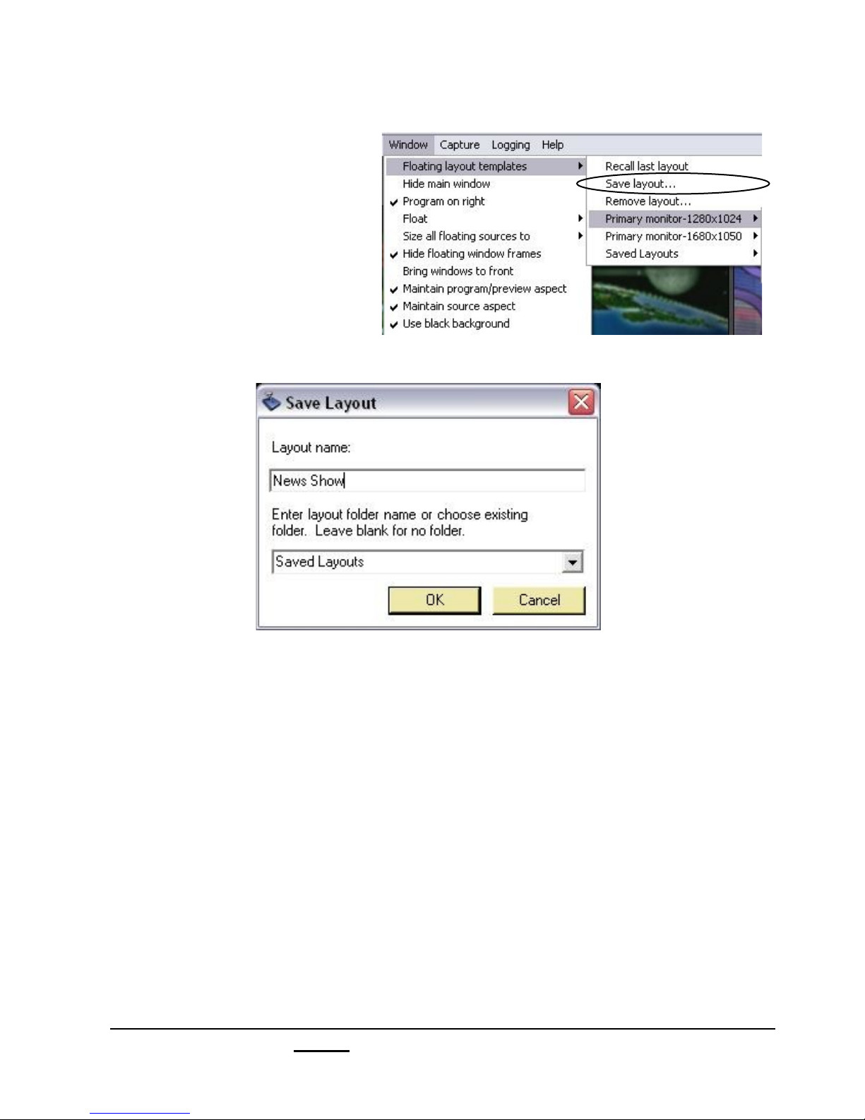
7.! You may save the layout
that you’ve created by,
selecting the Window drop
down menu, then Floating
layout templates, as
shown, and then select
Save layout… in the right
column, and the Save
Layout window will appear
as shown below.
8.! Enter the name you wish to give the layout in the Layout name field. You may
also save layouts in different sub-folders. Simply click in the Layout folder field
to enter the name of the folder, for example ‘Saved Layouts’. If no name is
entered, then your saved layout will appear in the main menu under the factorydesigned layouts .
9.! Click OK to save it. Now it will appear in the Floating layout templates drop down
list where you can recall it in the future.
10. You can also remove a saved layout by selecting Remove Layout… in the
above list.
Broadcast Pix V7.0
install - concepts - PixMaster - switcher - CG - clips - controls - team - appendix
2.5.9
Page 96
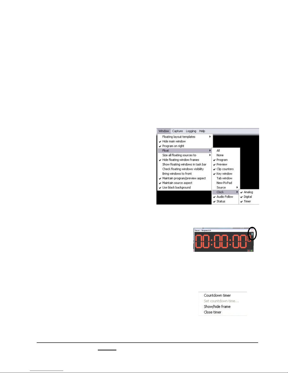
2.5.10 Clocks on the Multi-View
There are 3 types of clocks on the Broadcast Pix Multi-View: an Analog Clock, a
Digital Clock and a Timer. All three options are floatable, as described in the previous
section and all three can be floated at the same time. The analog clock provides a
graphical analog clock with a seconds hand and a small digital clock in both 12-hour
and 24-hour formats, this type of clock is not resizable. The digital clock provides a
green digital clock that updates every tenth of a second clock in both 12-hour
and 24-hour formats, this type of clock is resizable. The timer can set to either be a
red stopwatch/count up clock or a countdown clock (useful when timing out the end
of your production), this type of clock is resizable.
To float a clock:
1.! Select the Window drop down menu.
2.! Select the Float option.
3.! Select the Clock option.
4.! From the available drop down menu
select Analog, Digital and/or Timer.
A checkmark will appear next to the
Floating clocks, as shown on the right.
To select between Stopwatch and Countdown Timers:
1.! Float the Timer clock, as described above.
The red Timer window will appear, drag and
resize to your liking.
2.! Left-Click on the blue arrow in the upper right
hand corner of the window. This toggle button
switches between a Stopwatch and Countdown timer.
You may also Right-click anywhere in the timer
window, and a pop-up menu will appear, as shown
on the right.
If the Timer window is set to Stopwatch left-click
on Countdown timer. If the Timer window
is set to Countdown left-click on Stopwatch timer.
Broadcast Pix V7.0
install - concepts - PixMaster - switcher - CG - clips - controls - team - appendix
2.5.10
Page 97
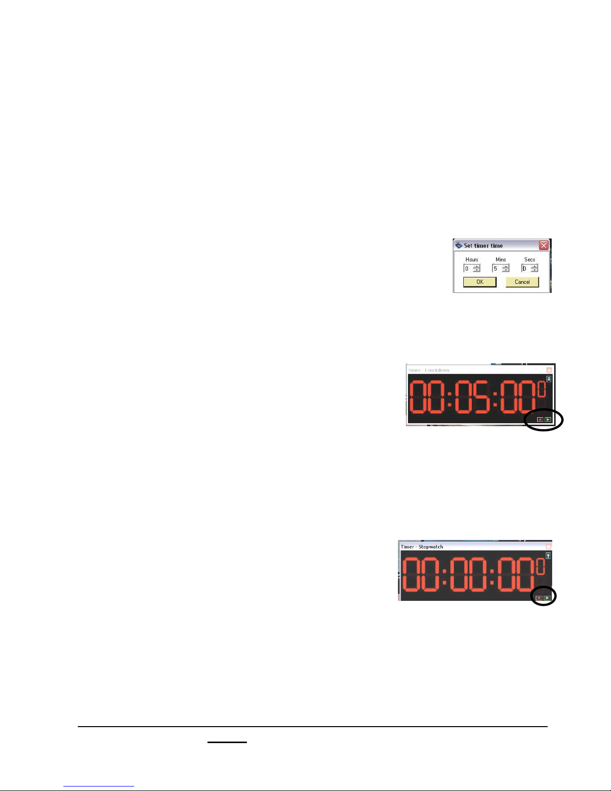
To operate a Countdown Timer:
1.! Activate the Timer window and set it as a
Countdown timer, as described above.
2. Right-click anywhere on the timer window and
and a pop-up menu will appear.
3. Select Set countdown time… from the available
list.
This will open the Set timer time window.
4.! In the pop-up window enter the hours, minutes
and/or seconds, as shown to the right.
5. Click on OK to save and exit the window. The
time that you entered will now appear in the
Countdown timer window.
6.! To start and pause the countdown, left-click on
the green play/triangle button in the lower right
hand corner of the timer window.
7.! To stop the countdown, left-click on the red
stop/square button in the lower left hand corner
of the timer window.
To operate a Stopwatch Timer:
1.! Activate the Timer window and it as Stopwatch
timer, as described on the previous page.
2. To start/pause the stopwatch, left-click on the
green play/triangle button in the lower right
hand corner of the timer window.
3. To stop and reset the stopwatch zero, left-click
on the red stop/square button in the lower left
hand corner of the timer window.
Broadcast Pix V7.0
install - concepts - PixMaster - switcher - CG - clips - controls - team - appendix
2.5.10
Page 98
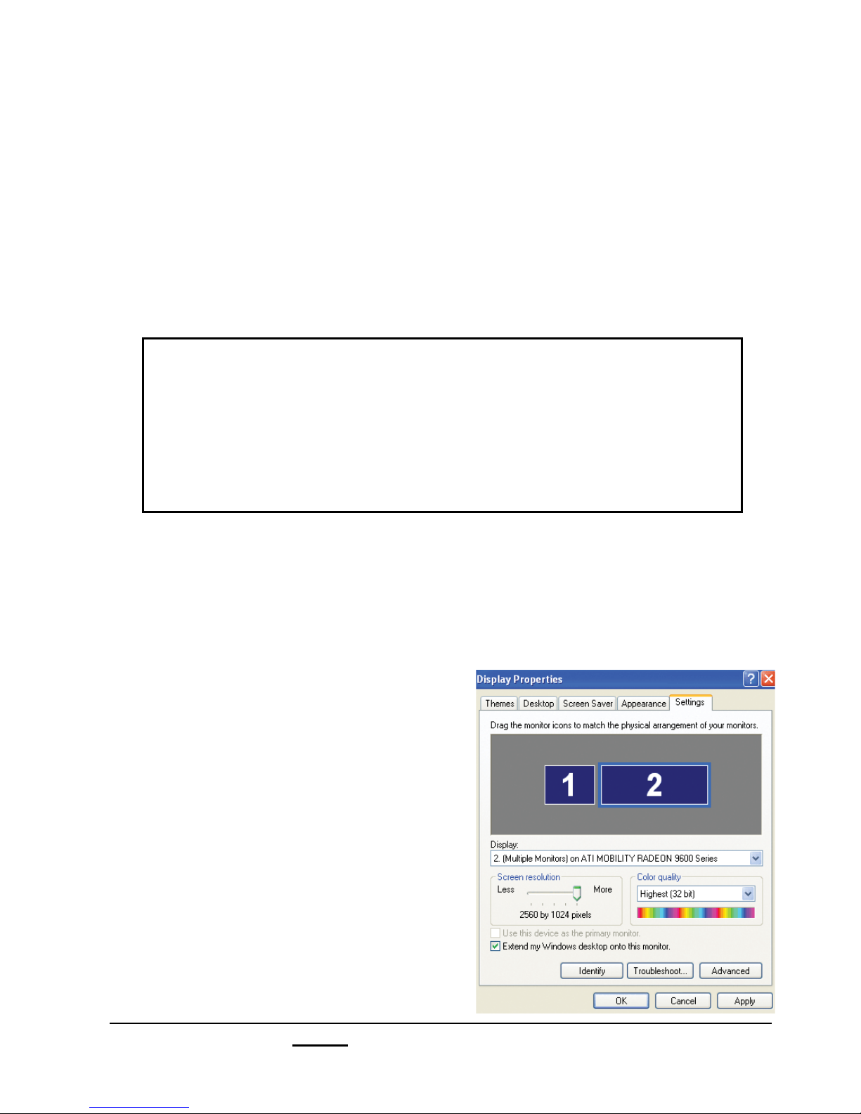
2.6 List of Screen Resolutions
Computer monitors should always be square pixels, and the display resolution should
have the same ratio as the aspect of the screen. The aspect of screen should never
be compensated for, this would distort text and images making them look too wide or
skinny. Below is a list of Monitor Resolutions with their native aspect ratios for easy
reference. If your monitor is “wide-screen” use a 16:9 or a 16:10 resolution. For
normal square screens use a 4:3 resolution. This is important when choosing a
monitor to use with your Multi-View or Floating Monitors to ensure proper
viewing/monitoring. You may use any screen resolution for Floating Monitors,
currently the Multi-View supports only 1280x1024 and 1680x1050 screen resolutions.
4:3 Aspect Ratio 16:9 Aspect Ratio 16:10 Aspect Ratio
1024"768 1024"576 1280"800
1152"864 1280"720 1440"900
1280"1024 1366"768 1680"1050
1400"1050 1920"1080 1920"1200
1600"1200 2048"1152 2560"1600
2048"1536
It is important to set your Windows desktop settings prior to starting the Broadcast Pix
Switcher application. It is not advised to change the desktop resolutions while the
application is running. Be advised that some large LCD/Plasma monitors do not accept
high resolutions on the VGA input, but do on a HDMI input. A DVI to HDMI cable or
converter may be necessary, refer to your monitors user’s manual for more information.
2.6.1 Adjusting the Windows Desktop Screen Resolution
1.! Right-Click on any blank area of the
Windows desktop of the computer
(again making sure that BPswitcher
is not running).
2. Select Properties from the pop up menu.
This will bring up the Display Properties
Window.
3. Select the Settings tab, as shown.
4. Select the monitor which you want
to modify, and in the Screen Resolution
section select the appropriate setting for
your monitor.
5. Select OK to save your changes.
Broadcast Pix V7.0
install - concepts - PixMaster - switcher - CG - clips - controls - team - appendix
2.6
Page 99

2.6.2 Optional Quad Monitor Card
As an option you can upgrade the standard dual monitor card to a quad monitor card,
which gives you up to four monitor outputs for your Multi-View in either DVI or VGA at a
maximum analog resolution of 2048x1536 @ 75Hz and a maximum digital resolution of
1920x1200 @ 60Hz on each output. The dual card has a maximum analog resolution of
2048x1536 @ 85Hz and a maximum digital resolution of 2560x1600 @ 60 Hz.
The Multi-View output is in the sixth PCI card slot on the back of the workstation. Do not
confuse the quad card Multi-View output with the DVI I/O card (if installed), as they use
the same DMS type connector.
The four monitor outputs are connected through a dual DMS-59 connection, as shown
below, and use breakout cables to a dual DVI-D or VGA connectors.
The top DMS connector is monitor output 1 and 3 and the bottom DMS connector is
monitor output 2 and 4.
DVI
Multi
Monitor
Outputs
2 & 4
NOTE: The maximum resolution of either monitor card depends on the resolution capabilities of the
monitor you are connecting.
Broadcast Pix V7.0
install - concepts - PixMaster - switcher - CG - clips - controls - team - appendix
HD
View
Monitor
Outputs
1 & 3
2.6.2
Page 100

2.7 Keyboard Shortcuts
Every Slate 100 system (optional on other Slate systems) comes with a custom colorcoded Broadcast Pix keyboard, as shown below. The keyboard acts as a control panel
to give you greater control than what the software can provide. Although not every
button which is on the control panel is on the custom keyboard, the essentials are at
your fingertips. Even though you may not have a custom keyboard, keyboard shortcuts
can still be enabled and used on any Broadcast Pix Slate system.
Broadcast Pix Custom Shortcuts Keyboard
2.7.1 Enabling Keyboard Shortcuts
You can enable keyboard shortcuts in one of two ways, either from the keyboard or
from a drop down menu in BPswitcher.
To enable shortcuts from the software:
1.! In BPswitcher select the Panel drop down menu,
as shown at the right.
2.! Select Keyboard Shortcuts (Shift + Backspace),
by making sure a check mark is active.
Broadcast Pix V7.0
install - concepts - PixMaster - switcher - CG - clips - controls - team - appendix
2.7
 Loading...