

Page 1

FM–5T
FM–5TS
5 KILOWATT
FM BROADCAST
TRANSMITTERS
July, 1999 IM No. 597–0033–014
Page 2

IMPORTANT INFORMATION
EQUIPMENT LOST OR DAMAGED IN TRANSIT.
When delivering the equipment to you, the truck driver or carrier’s agent will present a receipt for your signature.
Do not sign it until you have: 1) inspected the containers for visible signs of damage and 2) counted the containers
and compared with the amount shown on the shipping papers. If a shortage or evidence of damage is noted, insist
that notation to that effect be made on the shipping papers before you sign them.
Further, after receiving the equipment, unpack it and inspect thoroughly for concealed damage. If concealed damage is discovered, immediately notify the carrier, confirming the notification in writing, and secure an inspection report. This item should be unpacked and inspected for damage WITHIN 15 DA YS after receipt. Claims for loss or
damage will not be honored without proper notification of inspection by the carrier.
RF PRODUCT TECHNICAL ASSISTANCE – REPAIR SERVICE – REPLACEMENT PARTS.
Technical assistance is available from Broadcast Electronics by letter, prepaid telephone, fax, or E–mail. Equipment requiring repair or overhaul should be sent by common carrier, prepaid, insured, and well protected. If proper
shipping materials are not available, contact the Customer Service Department for a shipping container. Do not the
mail equipment. We can assume no liability for inbound damage, and necessary repairs become the obligation of
the shipper. Prior arrangement is necessary. Contact the Customer Service Department for a Return Authorization.
Emergency and warranty replacement parts may be ordered from the following address. Be sure to include the
equipment model number, serial number, part description, and part number. Non–emergency replacement parts
may be ordered directly from the Broadcast Electronics stock room by fax at the number shown below.
FACILITY CONTACTS –
Broadcast Electronics, Inc. – Quincy Facility
4100 N. 24th St. P.O. BOX 3606
Quincy, Illinois 62305
Telephone: (217) 224–9600
Fax: (217) 224–9607
E–Mail: General – [email protected]
Web Site: www .bdcast.com
RF PRODUCT TECHNICAL ASSIST ANCE – REPAIR – EMERGENCY/WARRANTY REPLACEMENT PARTS –
Telephone: (217) 224–9600
E–Mail: [email protected]
Fax: (217) 224–9607
NON–EMERGENCY REPLACEMENT PARTS –
Fax: (217) 224–9609
RETURN, REPAIR, AND EXCHANGES.
Do not return any merchandise without our written approval and Return Authorization. We will provide special shipping instructions and a code number that will assure proper handling and prompt issuance of credit. Please furnish
complete details as to circumstances and reasons when requesting return of merchandise. All returned merchandise must be sent freight prepaid and properly insured by the customer.
WARRANTY ADJUSTMENT.
Broadcast Electronics, Inc. warranty is included in the Terms and Conditions of Sale. In the event of a warranty
claim, replacement or repair parts will be supplied F.O.B. factory. At the discretion of Broadcast Electronics, the
customer may be required to return the defective part or equipment to Broadcast Electronics, Inc. F.O.B. Quincy,
Illinois. Warranty replacements of defective merchandise will be billed to your account. This billing will be cleared
by a credit issued upon return of the defective item.
PROPRIETARY NOTICE.
This document contains proprietary data of Broadcast Electronics, Inc. No disclosure, reproduction, or use of any
part thereof may be made except by prior written permission.
MODIFICATIONS.
Broadcast Electronics, Inc. reserves the right to modify the design and specifications of the equipment in this manual without notice. Any modifications shall not adversely affect performance of the equipment so modified.
Page 3

WARNING
OPERATING HAZARDS
READ THIS SHEET AND OBSERVE ALL SAFETY PRECAUTIONS
ALL PERSONS WHO WORK WITH OR ARE EXPOSED TO POWER TUBES, POWER TRANSISTORS, OR EQUIPMENT WHICH UTILIZES SUCH DEVICES MUST TAKE PRECAUTIONS TO PROTECT THEMSELVES AGAINST
POSSIBLE SERIOUS BODILY INJURY. EXERCISE EXTREME CARE AROUND SUCH PRODUCTS. UNINFORMED OR CARELESS OPERATION OF THESE DEVICES CAN RESULT IN POOR PERFORMANCE, DAMAGE
TO THE DEVICE OR PROPERTY, SERIOUS BODILY INJURY, AND POSSIBLY DEATH.
DANGEROUS HAZARDS EXIST IN THE OPERATION OF POWER TUBES AND POWER TRANSISTORS
The operation of power tubes and power transistors involves one or more of the following hazards, any one of which,
in the absence of safe operating practices and precautions, could result in serious harm to personnel.
A. HIGH VOLTAGE – Normal operating voltages can be deadly. Additional information follows.
B. RF RADIATION – Exposure to RF radiation may cause serious bodily injury possibly resulting in
blindness or death. Cardiac pacemakers may be affected. Additional information follows.
C. BERYLLIUM – OXIDE POISONING – Dust or fumes from BeO ceramics used as thermal links with
conduction cooled power tubes and power transistors are highly toxic and can cause serious injury or
death. Additional information follows.
D. HOT SURFACES – Surfaces of air–cooled radiators and other parts of tubes can reach temperatures of
several hundred degrees centigrade and cause serious burns if touched. Additional information follows.
E. RF BURNS – Circuit boards with RF power transistors contain high RF potentials. Do not operate an RF
power module with the cover removed.
HIGH VOLTAGE
Many power tubes operate at voltages high enough to kill through electrocution. Personnel should always break the
primary circuits of the power supply and discharge high voltage capacitors when direct access to the tube is required.
RADIO FREQUENCY RADIATION
Exposure of personnel to RF radiation should be minimized, personnel should not be permitted in the vicinity of open
energized RF generating circuits, or RF transmission systems (waveguides, cables, connectors, etc.), or energized
antennas. It is generally accepted that exposure to “high levels” of radiation can result in severe bodily injury including blindness. Cardiac pacemakers may be affected.
The effect of prolonged exposure to “low level” RF radiation continues to be a subject of investigation and controversy. It is generally agreed that prolonged exposure of personnel to RF radiation should be limited to an absolute minimum. It is also generally agreed that exposure should be reduced in working areas where personnel heat load is
above normal. A 10 mW/cm
cies including the Occupational Safety and Health Administration (OSHA) as the standard protection guide for employee work environments. An even stricter standard is recommended by the American National Standards Institute
which recommends a 1.0 mW/cm
standard employee protection guide (ANSI C95.1–1982).
RF energy must be contained properly by shielding and transmission lines. All input and output RF connections, such
as cables, flanges and gaskets must be RF leakproof. Never operate a power tube without a properly matched RF
energy absorbing load attached. Never look into or expose any part of the body to an antenna or open RF generating
tube or circuit or RF transmission system while energized. Monitor the tube and RF system for RF radiation leakage
at regular intervals and after servicing.
DANGER –– BERYLLIUM OXIDE CERAMICS (BeO) – AVOID BREATHING DUST OR FUMES
BeO ceramic material is used as a thermal link to carry heat from a tube or transistor to the heat sink. Do not perform
any operation on any BeO ceramic which might produce dust or fumes, such as grinding, grit blasting, or acid cleaning. Beryllium oxide dust or fumes are highly toxic and breathing them can result in serious personal injury or death.
BeO ceramics must be disposed of only in a manner prescribed by the device manufacturer.
HOT SURFACES
The anode portion of power tubes is often air–cooled or conduction–cooled. The air–cooled external surface normally
operates at a high temperature (up to 200° to 300°C). Other portions of the tube may also reach high temperatures,
especially the cathode insulator and the cathode/heater surfaces. All hot surfaces may remain hot for an extended
time after the tube is shut off. To prevent serious burns, take care to prevent and avoid any bodily contact with these
surfaces both during and for a reasonable cooling down period after tube operation.
2
per one tenth hour average level has been adopted by several U.S. Government agen-
2
per one tenth hour average level exposure between 30 Hz and 300 mHz as the
Page 4

PUBLICATION ADDENDUM
SPECIAL ASSEMBLY REQUIREMENTS
FM-5T/FM-5TS TRANSMITTERS
1-1. INTRODUCTION.
1-2. Due to special shipping requirements, selected components of the Broadcast Electronics
FM-5T/FM-5TS transmitters have been disassembled to prevent damage during ship
ment. This publication addendum provides information required for the re-assembly of
the transmitter IN ADDITION TO the information provided in SECTION II, INSTALLA
TION of FM-5T/FM-5TS instruction manual 597-0033-004. Perform the following as
sembly instructions prior to executing the procedures described in the instruction manual.
1-3.
1-4. GENERAL.
1-5. Components removed from the transmitter contain identification tags to facilitate
1-6. Terminal blocks and wires contain identification tags with information regarding reconnec
SPECIAL ASSEMBLY.
re-installation. Items such as interconnecting wires, cables, and miscellaneous small
parts are taped or tied for shipment. Remove all tape, string, and packing material used
for shipping purposes as each item is installed.
tion. Mounting hardware will be placed in small bags attached to each removed compo
nent or inserted in the component mounting holes.
WARNING
ENSURE NO PRIMARY POWER IS CONNECTED TO
THE TRANSMITTER BEFORE PROCEEDING.
WARNING
1-7. INSTALLATION.
1-8. TRANSMITTER BASE PLATE. Install components removed from the transmitter base plate
by performing the following procedures. Ensure no primary power is applied to the trans
mitter before any component installation.
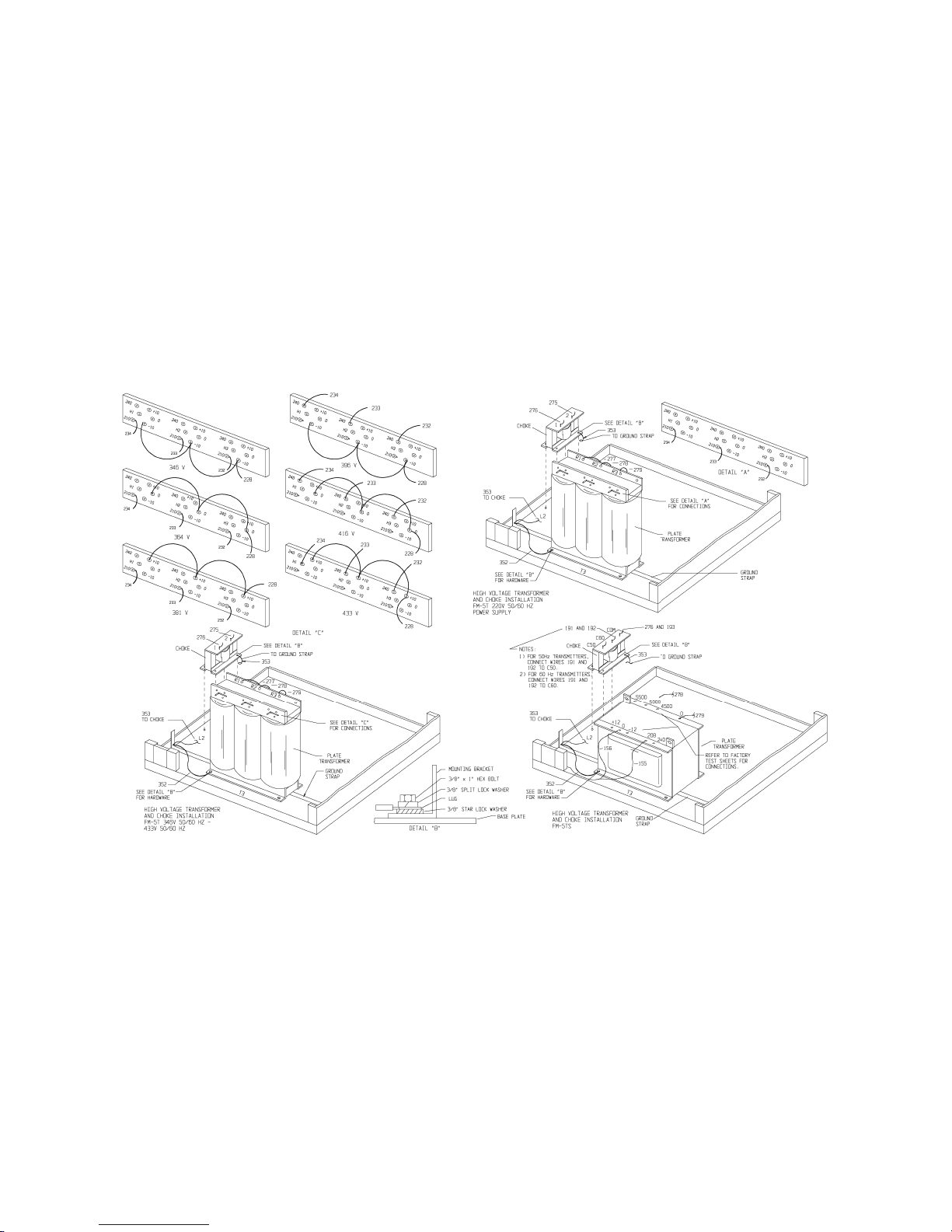
1-9. Plate Transformer Installation. Refer to Figure 1 and install the plate transformer as fol
lows:
A. Using a small fork-lift, place the plate transformer on the transmitter base plate as
indicated.
B. Secure the plate transformer to the transmitter base plate with four 3/8 inch bolts,
flat washers, and lock washers.
WARNING
WARNING
C. Connect wire 352 from the cabinet ground strap to the plate transformer base as
indicated.
D. Connect the appropriate wires to the plate transformer terminals as indicated.
ENSURE THE GROUND WIRE ON THE PLATE TRANS
FORMER BASE IS PROPERLY CONNECTED TO THE
CABINET GROUND STRAP.
--
1
Page 5

1-10. Plate Choke Installation. Refer to Figure 1 and install the plate choke as follows:
A. Place the plate choke on the transmitter base plate as indicated.
B. Secure the plate choke to the transmitter base plate with four 3/8 inch bolts, flat
washers, and lock washers.
WARNING
ENSURE THE GROUND WIRE ON THE PLATE CHOKE
BASE IS PROPERLY CONNECTED TO THE CABINET
WARNING
C. Connect wire 353 from the cabinet ground strap to the plate choke base as indi-
cated.
D. Connect the appropriate wires to the plate choke terminals as indicated.
WARNING
GROUND STRAP.
ENSURE NO PRIMARY POWER IS CONNECTED TO
THE TRANSMITTER BEFORE PROCEEDING.
WARNING
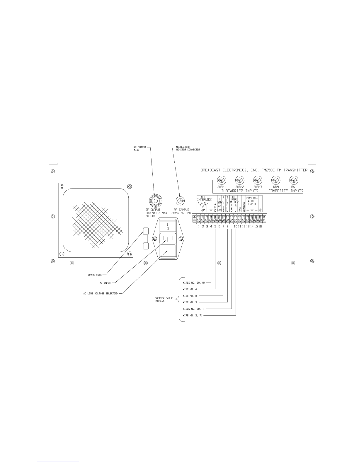
1-11. EXCITER INSTALLATION. Refer to Figure 2 and install the exciter. Ensure no primary
power is applied before any component installation. The exciter is installed by lifting the
unit onto the slide-rails.
-
2-
Page 6
597-0033-414
FIGURE 1. HIGH VOLTAGE TRANSFORMER
AND CHOKE INSTALLATION
(-3-/-4-)
COPYRIGHT 1997 BROADCAST ELECTRONICS, INC
Page 7
5
--
COPYRIGHT 1997 BROADCAST ELECTRONICS, INC
597-0098-408
FIGURE 2. FM-250C REAR-PANEL CONNECTIONS
Page 8

SCOPE OF MANUAL
This manual consists of two sections providing the following information for the Broadcast
Electronics FM-5T/FM-5TS 5 kW FM Broadcast Transmitters.
A. PART I - Contains information relative to installation, operation, and
maintenance applicable to the overall transmitter.
B. PART II - Contains detailed information for the following transmitter
modular units.
TRANSMITTER CONTROLLER
PART I - TABLE OF CONTENTS
PARAGRAPH PAGE NO.
SECTION I GENERAL INFORMATION
1-1 INTRODUCTION 1-1
1-3 RELATED PUBLICATIONS 1-1
1-5 EQUIPMENT DESCRIPTION 1-1
1-7 TRANSMITTER CONFIGURATIONS 1-1
1-9 OPTIONAL EQUIPMENT AND SPARE PARTS KITS 1-1
1-11 EQUIPMENT SPECIFICATIONS 1-2
SECTION II INSTALLATION
2-1 INTRODUCTION 2-1
2-3 UNPACKING 2-1
2-6 ENVIRONMENTAL REQUIREMENTS 2-1
2-8 COOLING AIR REQUIREMENTS 2-1
2-12 INSTALLATION 2-1
2-14 PRIMARY AC POWER 2-1
2-15 FM-5T 2-1
2-18 FM-5TS 2-2
2-19 EQUIPMENT PLACEMENT 2-2
2-22 COMPONENT INSTALLATION 2-2
2-49 REMOTE CONTROL 2-6
2-85 WIRING 2-12
2-86 TRANSFORMER TAPS 2-12
2-87 INPUT VOLTAGE CHECK 2-12
2-88 OPTIONAL EQUIPMENT WIRING 2-12
2-89 SIGNAL INPUTS 2-12
2-90 FAILSAFE INTERLOCK 2-12
2-91 TRANSMITTER MONITORING - MODEM 2-14
CONNECTIONS
2-92 TRANSMITTER MONITORING - PRINTER 2-14
CONNECTIONS
2-93 AC POWER CONNECTIONS 2-14
2-94 FM-5T 2-15
2-96 FM-5TS 2-15
2-98 INITIAL CHECKOUT 2-15
2-106 CONTROLLER AND INTERLOCK CHECKOUT 2-17
Broadcast Electronics 1997
ALL RIGHTS RESERVED
Printed in the U.S.A.
––
i
Page 9

PARAGRAPH PAGE NO.
2-115 BLOWER CHECKOUT 2-18
2-119 EXCITER CHECKOUT 2-19
2-126 PRELIMINARY OPERATION AND TUNING 2-19
SECTION III OPERATION
3-1 INTRODUCTION 3-1
3-3 CONTROLS AND INDICATORS 3-1
3-5 OPERATION 3-1
3-6 TURN ON 3-1
3-16 TURN OFF 3-2
3-19 OPERATING THE TRANSMITTER FOR MAXIMUM 3-2
TUBE LIFE
3-21 CONTINUOUSLY FLASHING CONTROLLER 3-2
SWITCH/INDICATOR
SECTION IV THEORY OF OPERATION
4-1 INTRODUCTION 4-1
4-4 ELECTRICAL DESCRIPTION 4-1
4-5 FM EXCITER 4-1
4-8 POWER AMPLIFIER 4-1
4-10 POWER AMPLIFIER CAVITY 4-1
4-11 OUTPUT COUPLING 4-2
4-12 PLATE TUNING 4-2
4-13 NEUTRALIZATION 4-2
4-14 SECOND HARMONIC SUPPRESSOR 4-2
4-15 OUTPUT CIRCUIT 4-2
4-16 TRANSMITTER CONTROLLER 4-2
4-22 AUTOMATIC RF OUTPUT LEVEL CONTROL 4-5
4-24 VSWR FOLDBACK PROTECTION 4-5
4-25 SOFT START 4-5
4-26 MOMENTARY POWER INTERRUPTION 4-5
4-27 OVERLOADS 4-5
4-28 INDICATORS 4-5
4-30 METERING 4-6
4-33 EXCITER METERING 4-6
4-34 POWER SUPPLIES 4-6
4-40 DETAILED DESCRIPTION 4-7
4-41 FM-5T POWER SUPPLY 4-7
4-43 SEQUENCE OF OPERATION 4-7
4-48 PA PLATE POWER SUPPLY 4-7
4-53 PA SCREEN GRID POWER SUPPLY 4-8
4-54 PA CONTROL GRID POWER SUPPLY 4-8
4-56 PA FILAMENT SUPPLY 4-8
4-57 FM-5TS POWER SUPPLY 4-11
4-59 SEQUENCE OF OPERATION 4-11
4-64 PA PLATE POWER SUPPLY 4-11
4-66 PA SCREEN GRID POWER SUPPLY 4-12
4-67 PA CONTROL GRID POWER SUPPLY 4-12
4-69 PA FILAMENT SUPPLY 4-12
4-70 RF CIRCUITRY 4-12
4-71 FM EXCITER 4-12
--
ii
Page 10

PARAGRAPH PAGE NO.
4-72 POWER AMPLIFIER 4-12
4-81 PA METERING 4-16
4-82 AUTOMATIC POWER CONTROL 4-16
SECTION V MAINTENANCE
5-1 INTRODUCTION 5-1
5-3 SAFETY CONSIDERATIONS 5-1
5-9 FIRST LEVEL MAINTENANCE 5-2
5-12 CONTROLLER BATTERY 5-2
5-14 AIR FILTER 5-2
5-17 BLOWER MAINTENANCE 5-3
5-21 SECOND LEVEL MAINTENANCE 5-3
5-23 GENERAL 5-3
5-24 PA STAGE 5-3
5-26 ADJUSTMENTS 5-4
5-28 AM NOISE 5-5
5-37 PLATE CURRENT METER CALIBRATION 5-5
5-38 SECOND HARMONIC SUPPRESSOR 5-6
5-61 NEUTRALIZATION 5-9
5-96 TRANSMITTER POWER LEVEL CHANGE 5-13
5-98 TRANSMITTER FREQUENCY CHANGE 5-13
PROCEDURE
5-99 GENERAL 5-13
5-111 TROUBLESHOOTING 5-14
5-114 COMPONENT REPLACEMENT ON CIRCUIT 5-17
BOARDS
SECTION VI PARTS LISTS
6-1 INTRODUCTION 6-1
SECTION VII DRAWINGS
7-1 INTRODUCTION 7-1
APPENDIX A MANUFACTURERS DATA
A-1 INTRODUCTION A-1
LIST OF TABLES
TABLE NO. DESCRIPTION PAGE NO.
1-1 ELECTRICAL CHARACTERISTICS 1-2
1-2 PHYSICAL CHARACTERISTICS 1-5
3-1 FM-5T/FM-5TS PA/DRIVER CABINET CONTROLS AND 3-2
INDICATORS
3-2 INDICATOR CHECKLIST 3-9
5-1 TYPICAL METER INDICATIONS (5 KW RF OUTPUT) 5-16
5-2 TYPICAL POWER DEMAND (5 KW RF OUTPUT) 5-16
6-1 REPLACEMENT PARTS LIST INDEX 6-1
--
iii
Page 11

LIST OF ILLUSTRATIONS
FIGURE NO. DESCRIPTION PAGE NO.
1-1 FM-5T/FM-5TS TRANSMITTER 1-3
2-1 FM-5T/FM-5TS TRANSMITTER INSTALLATION 2-3
2-2 ACCEPTABLE AC POWER INPUT CONFIGURATIONS 2-5
2-3 REMOTE CONTROL INTERFACING 2-7
2-4 TRANSFORMER TAPS 2-13
2-5 OPTIONAL EQUIPMENT WIRING 2-14
2-6 FM-5T PRIMARY AC WIRING 2-16
2-7 FM-5TS PRIMARY AC WIRING 2-17
3-1 CONTROLS AND INDICATORS 3-3
4-1 FM-5T/FM-5TS BLOCK DIAGRAM 4-3
4-2 FM-5T POWER SUPPLY SIMPLIFIED SCHEMATIC 4-9
4-3 FM-5TS POWER SUPPLY SIMPLIFIED SCHEMATIC 4-13
4-4 RF CIRCUIT SIMPLIFIED SCHEMATIC 4-17
4-5 PA CAVITY 4-19
5-1 TYPICAL PA EFFICIENCY CURVE AT 98.1 MHZ 5-4
5-2 HUM NULL CONTROL LOCATION 5-6
5-3 SECOND HARMONIC SUPPRESSOR COARSE SETTING 5-8
5-4 NEUTRALIZATION STRAP COARSE SETTING 5-11
5-5 COARSE TUNING ADJUSTMENTS 5-15
5-6 FM-5T CABINET COMPONENT LOCATOR, FRONT 5-19
5-7 FM-5TS CABINET COMPONENT LOCATOR, FRONT 5-20
5-8 PA CAVITY COMPONENT LOCATOR 5-21
5-9 FM-5T/FM-5TS CABINET COMPONENT LOCATOR, 5-23
REAR
5-10 PA TUBE SOCKET 5-25
PART II - TABLE OF CONTENTS
I - TRANSMITTER CONTROLLER
--
iv
Page 12

SECTION I
GENERAL INFORMATION
1-1. INTRODUCTION.
1-2. Information presented by this section provides a general description of the
FM-5T/FM-5TS FM transmitters and lists equipment specifications.
1-3. RELATED PUBLICATIONS.
1-4. The following list of publications provides data for equipment associated with the
FM-5T/FM-5TS transmitters.
PUBLICATION NUMBER EQUIPMENT
597-1004 FM-250C FM Exciter
597-0008-004 FC-30 SCA Generator
597-9900 LYNX FM Digital Stereo Generator
597-8000 PREDATOR FM Digital Exciter
1-5.
1-6. The Broadcast Electronics FM-5T/FM-5TS are 5 kW FM Transmitters designed for con
1-7.
1-8. The FM-5T/FM-5TS transmitters may be ordered in the following configurations.
MODEL NO. PART NUMBER DESCRIPTION
FM-5T 909-5000-215 FM-5T 5 kW FM transmitter complete with FM-250C
FM-5T 909-5000-315 FM-5T 5 kW FM transmitter complete with FM-250C
FM-5T 909-5000-385 FM-5T 5 kW FM transmitter complete with FM-250C
FM-5TS 909-5000-255 FM-5T 5 kW FM transmitter complete with FM-250C
EQUIPMENT DESCRIPTION.
tinuous operation in the 87.5 MHz to 108 MHz FM broadcast band. The RF power ampli
fier, FM exciter, and the control circuitry are housed in a single cabinet (see Figure 1-1).
Specific transmitter features include: 1) a folded half wave cavity PA stage, 2) a micropro
cessor control system, and 3) a 250 watt solid-state exciter with a digital frequency synthe
sizer. The following text presents ordering information for various transmitter configura
tions, optional equipment, and recommended spare parts kits.
TRANSMITTER CONFIGURATIONS.
FM Exciter, 208/240V ac three phase 60 Hz operation.
FM Exciter, 208/240V ac three phase 50 Hz operation.
FM Exciter, 339V/437V ac three phase 50 Hz operation.
FM Exciter, 208/240V ac single phase 60 Hz operation.
FM-5TS 909-5000-355 FM-5T 5 kW FM transmitter complete with FM-250C
1-9.
1-10. The following optional equipment and spare parts kits are available for use in the
OPTIONAL EQUIPMENT AND SPARE PARTS KITS.
FM-5T/FM-5TS transmitters:
FM Exciter, 208/240V ac single phase 50 Hz operation.
1-1
Page 13

PART NUMBER DESCRIPTION
909-9000 LYNX FM digital stereo generator.
909-0051-204 FC-30 FM SCA generator.
909-8250 PREDATOR 250 Watt FM Digital Exciter And
Digital Input.
909-8251 PREDATOR 250 Watt FM Digital Exciter And
Analog Input.
909-8252 PREDATOR 250 Watt FM Analog Exciter And
Analog Input.
907-0016-034 VMC-16 Voice Remote Control Unit, FM-5T.
907-0016-094 VMC-16 Voice Remote Control Unit, FM-5TS.
979-0035-004 Recommended spare parts kit for the FM-5T/
FM-5TS and the FX-50 exciter. Includes
selected meters, switches, relays, etc. Does
not include semiconductors.
979-0095 Recommended semiconductor kit for the
FM-5T/FM-5TS and FM-250 exciter.
979-0095-005 Recommended semiconductor kit for the
FM-5T/FM-5TS transmitter only. Does not
include exciter spare semiconductors.
979-0095-015 Recommended spare parts kit for the FM-5T/
FM-5TS transmitters only. Includes selected
meters, switches, relays, etc. Does not include
semiconductors.
979-0034-014 Recommended spare HV rectifier kit for the
FM-5T/FM-5TS transmitters.
1-11.
1-12. Refer to Table 1-1 for electrical specifications or Table 1-2 for physical specifications of the
RF POWER OUTPUT 2500 to 5500 Watts (as ordered).
RF FREQUENCY RANGE 87.5 to 108 MHz (as ordered). Exciter program-
RF OUTPUT IMPEDANCE 50 Ohms, Resistive (others available by special
RF OUTPUT CONNECTOR 1 5/8 Inch (4.13 cm) EIA flange.
MAXIMUM VSWR 1.8:1 (Will operate into higher VSWR with auto-
TUBE COMPLEMENT 4CX3500A (1).
EQUIPMENT SPECIFICATIONS.
FM-5T/FM-5TS FM Transmitters.
TABLE 1-1. ELECTRICAL CHARACTERISTICS
(Sheet 1 of 3)
PARAMETER SPECIFICATIONS
mable in 10 kHz increments.
request).
matic power reduction).
1-2
Page 14
COPYRIGHT 1990 BROADCAST ELECTRONICS, INC
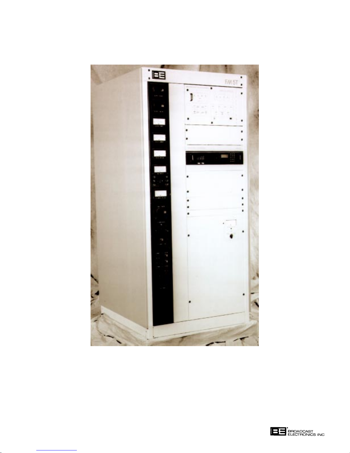
FIGURE 1-1. FM-5T/FM-5TS TRANSMITTER
597-0033-1
1-3
Page 15

TABLE 1-1. ELECTRICAL CHARACTERISTICS
(Sheet 2 of 3)
PARAMETER SPECIFICATIONS
FM SIGNAL-TO-NOISE RATIO:
Mono/Composite 82 dB below 100% modulation at 400 Hz measured
in a 20 Hz to 30 kHz bandwidth with 75 us deemphasis.
Stereo 78 dB below 100% modulation at 400 Hz measured
in a 20 Hz to 30 kHz bandwidth with 75 us deemphasis.
AM SIGNAL-TO-NOISE RATIO:
Asynchronous 55 dB below equivalent reference carrier with
100% AM at 400 Hz, 75 us deemphasis (no FM
modulation present).
Synchronous 40 dB below equivalent 5 kW reference carrier
with 100% AM at 1 kHz, no deemphasis (FM
modulation ±75 kHz at 1 kHz).
RF HARMONIC SUPPRESSION Meets all FCC/DOC requirements and CCIR rec-
ommendations.
POWER SUPPLY RECTIFIERS Silicon.
DISTORTION
Mono/Composite
Harmonic 0.03% or less at 400 Hz.
SMPTE Intermodulation 0.05% or less, 60 Hz/7 kHz, Ratio:
Distortion 4:1 Monophonic, 1:1 Composite.
CCIF Intermodulation
Distortion
Mono 0.02% or less, 15 kHz/14 kHz,1:1 Ratio.
Composite 0.03% or less, 15 kHz/14 kHz,1:1 Ratio.
Transient Intermodulation 0.02% or less, Sine Wave/Square Wave.
Distortion
Stereo
Harmonic 0.03% or less at 400 Hz.
SMPTE Intermodulation 0.05% or less, 60 Hz/7 kHz, 4:1 Ratio.
Distortion
CCIF Intermodulation 0.02% or less, 15 kHz/14 kHz, 1:1 Ratio.
Distortion
Transient Intermodulation 0.05% or less, Sine Wave/Square Wave.
Distortion
1-4
Page 16
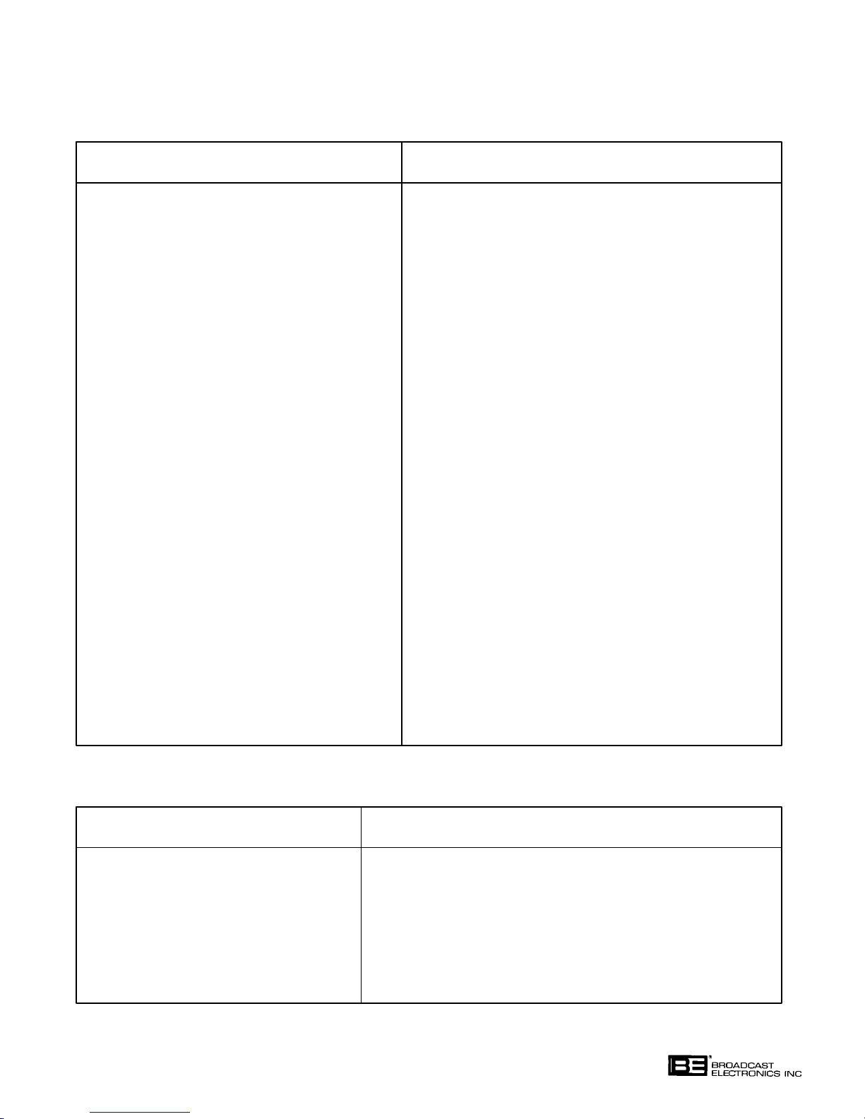
TABLE 1-1. ELECTRICAL CHARACTERISTICS
(Sheet 3 of 3)
PARAMETER SPECIFICATIONS
STEREO SEPARATION 50 dB or better, 30 Hz to 15 kHz.
DYNAMIC STEREO SEPARATION 40 dB or better, 30 Hz to 15 kHz (normal program
content).
LINEAR CROSSTALK 45 dB minimum below 100% modulation,
(Main to Sub/Sub to Main 30 Hz to 15 kHz.
Due to Phase Matching)
NON-LINEAR CROSSTALK 70 dB minimum below 100 % modulation.
(Main to Sub/Sub to Main
Due to Distortion Products)
AC INPUT POWER:
FM-5T 196 to 252V ac 50/60 Hz or 341V to 435V ac
50 Hz three phase closed-delta or wye (as
specified), 28 amperes per phase maximum.
FM-5TS 196 to 252V ac 50/60 Hz single phase (as speci-
fied), 55 amperes maximum.
AC POWER CONSUMPTION
FM-5T 8500 Watts typical at a 5 kW RF power output,
0.92 power factor.
FM-5TS 9600 Watts typical at a 5 kW RF power output,
0.98 power factor.
OVERALL EFFICIENCY
FM-5T 58% Typical (ac line input to RF output).
FM-5TS 52% Typical (ac line input to RF output).
TABLE 1-2. PHYSICAL CHARACTERISTICS
(Sheet 1 of 2)
PARAMETER SPECIFICATIONS
AMBIENT TEMPERATURE RANGE +14°F to +122°F (-10°C to +50°C).
MAXIMUM ALTITUDE
60 Hz Models 0 to 10,000 Feet above sea level
(0 to 3048 Meters).
50 Hz Models 0 to 7500 Feet above sea level
(0 to 2286 Meters).
1-5
Page 17

TABLE 1-2. PHYSICAL CHARACTERISTICS
(Sheet 2 of 2)
PARAMETER SPECIFICATIONS
MAXIMUM HUMIDITY 95%, Non-condensing.
HEAT DISSIPATION 3500 Watts maximum (11,945 BTU/Hr)
at 5000 Watts output.
COOLING AIR REQUIREMENT 800 ft3/min overall (22.6 m3/min).
SIZE:
WIDTH 34.5 Inches (87.63 cm).
DEPTH 37.25 Inches (94.61 cm).
HEIGHT 70 Inches (177.8 cm).
WEIGHT:
UNPACKED 1,000 Pounds (454 kg).
PACKED 1,200 Pounds (544 kg).
3
CUBAGE 60 Cubic Feet (1.7 m
).
1-6
Page 18

SECTION II
INSTALLATION
2-1. INTRODUCTION.
2-2. This section contains information required for installation and preliminary checkout of the
Broadcast Electronics FM-5T/FM-5TS FM Transmitters.
2-3. UNPACKING.
2-4. The equipment becomes the property of the customer when the equipment is delivered to
the carrier. Carefully unpack the transmitter. Perform a visual inspection to determine
that no apparent damage has been incurred during shipment. All shipping materials
should be retained until it is determined that the unit has not been damaged. Claims for
damaged equipment must be promptly filed with the carrier or the carrier may not accept
the claim.
2-5. The contents of the shipment should be as indicated on the packing list. If the contents are
incomplete, or if the unit is damaged electrically or mechanically, notify both the carrier
and Broadcast Electronics, Inc.
2-6.
2-7. Table 1-2 provides environmental conditions which must be considered prior to transmit
2-8. COOLING AIR REQUIREMENTS.
2-9. If outside air is to be used to cool the transmitter, the air inlet duct must be sized to allow
2-10. If the heated transmitter air is to be ducted from the room, the duct system must not intro
2-11. As a minimum requirement, any duct work must have a cross-sectional area equal to the
2-12.
2-13. Each transmitter is wired, operated, tested and inspected at the factory prior to shipment
ENVIRONMENTAL REQUIREMENTS.
ter installation.
adequate air flow. The air must be dry and well filtered. If intake louvers are used, opera
tion of the louvers must be electrically interlocked with the transmitter operation.
duce any back-pressure on the equipment. Proper allowances for air flow will ensure that
only a limited amount of heat is dissipated into the equipment interior. The duct system
must allow for a minimum air flow of 800 cubic feet of air per minute (22.6 m
exhaust area of the cabinet (refer to Figure 2-1). Sharp bends in the duct system will in
troduce back pressure and are not permissible. A radius bend must be used if a right angle
turn is required. An exhaust fan may be used to overcome duct losses or overcome wind
pressures if the duct is vented to the outside.
3
/min).
INSTALLATION.
and is ready for installation when received. Prior to installation, this publication should be
studied to obtain an understanding of the operation, circuitry nomenclature, and installa
tion requirements. Installation is accomplished as follows: 1) placement, 2) component
installation, 3) remote control connections, 4) wiring, and 5) initial checkout.
2-14.
2-15. FM-5T. The FM-5T transmitter is designed for operation from a closed-delta or wye con
PRIMARY AC POWER.
nected three-phase source. Operation from an unsatisfactory power source will void the
warranty on this transmitter as any resultant damage is beyond the control of the manu
facturer. Before attempting installation of the transmitter, assure that the proper power
source is installed. Acceptable power input configurations are shown in Figure 2-2.
2-1
Page 19

2-16. An open-delta, V to V, T to T, T to L, or Scott connected power source will provide unsatis
factory transmitter performance as transients and unstable power can damage components
of the FM-5T and degrade transmitter specifications. Any of these systems will develop a
considerable imbalance between phases in voltage, phase angle, or both voltage and phase
angle. These problems can result in premature failure of power supply and RF circuit com
ponents.
2-17. It is important that the local electric utility be consulted to ensure that the correct service
is provided before connection of the FM-5T transmitter to a primary power source. The
proper power source can readily be identified by the use of three transformers with one
winding each or one transformer with three windings instead of the use of two transform
ers as required for the unacceptable configurations.
2-18.
2-19. EQUIPMENT PLACEMENT.
2-20. Access holes in the top and bottom of the cabinet allow either overhead or under-floor
2-21. After it has been determined where and how the cabinet will be positioned, set the cabinet
2-22. COMPONENT INSTALLATION.
FM-5TS. The FM-5TS transmitter is designed for operation from a 220V ac 50/60 Hz sin
gle phase power source. Consult the local electric utility company to ensure that the cor
rect service is provided before connection of the transmitter to the primary power source.
ducting of interconnecting wiring (see Figure 2-1). The floor must be capable of support
ing the total transmitter weight of approximately 130 pounds per square foot. The floor
support should be more than marginal to maintain the proper cabinet alignment and re
duce vibration.
in place on a smooth and level location.
WARNING
ENSURE PRIMARY POWER IS DISCONNECTED BE
FORE PROCEEDING.
WARNING
2-23. Interconnecting wires and cables are tied in for shipment. Remove all tape, wire ties,
string, and packing material used for shipment. Remove the cover from the FAILSAFE
SOLENOID ASSEMBLY and cut loose all tie wraps, freeing the plunger. A No. 2 Phillips
screwdriver is required. Replace the cover. Also, remove all ties from the shorting stick
hanger.
2-24. Cables, connectors, and miscellaneous components to be installed are shipped in separate
containers. The following text provides information concerning the installation of these
items.
NOTE
NOTE
2-25. Connect the antenna to the transmitter. A 1 5/8 inch EIA flange is provided with the
transmitter to assist installation. The flange can remain off if unflanged connections are
desired. A center conductor bullet may be required (BE P/N 427-0009).
2-26. Open the transmitter rear door.
2-27. Remove the lower front access panel. A 5/32 inch hex key is shipped with the transmitter
for this purpose.
ENSURE ADJUSTMENTS ARE NOT MOVED FROM
THEIR FACTORY PRESET POSITIONS DURING IN
STALLATION.
2-2
Page 20
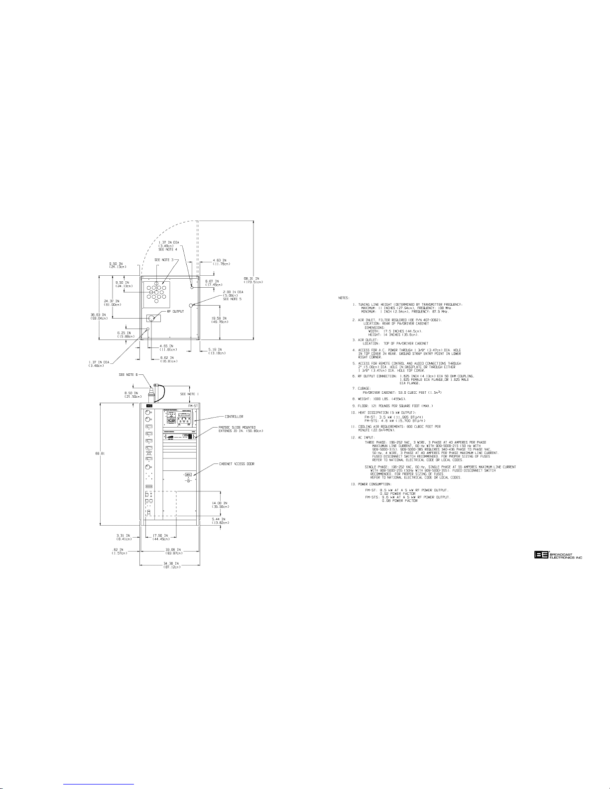
597-0033-400
FIGURE 2-1. FM-5T/FM-5TS TRANSMITTER
INSTALLATION
(2-3/2-4)
COPYRIGHT 1997 BROADCAST ELECTRONICS, INC
Page 21
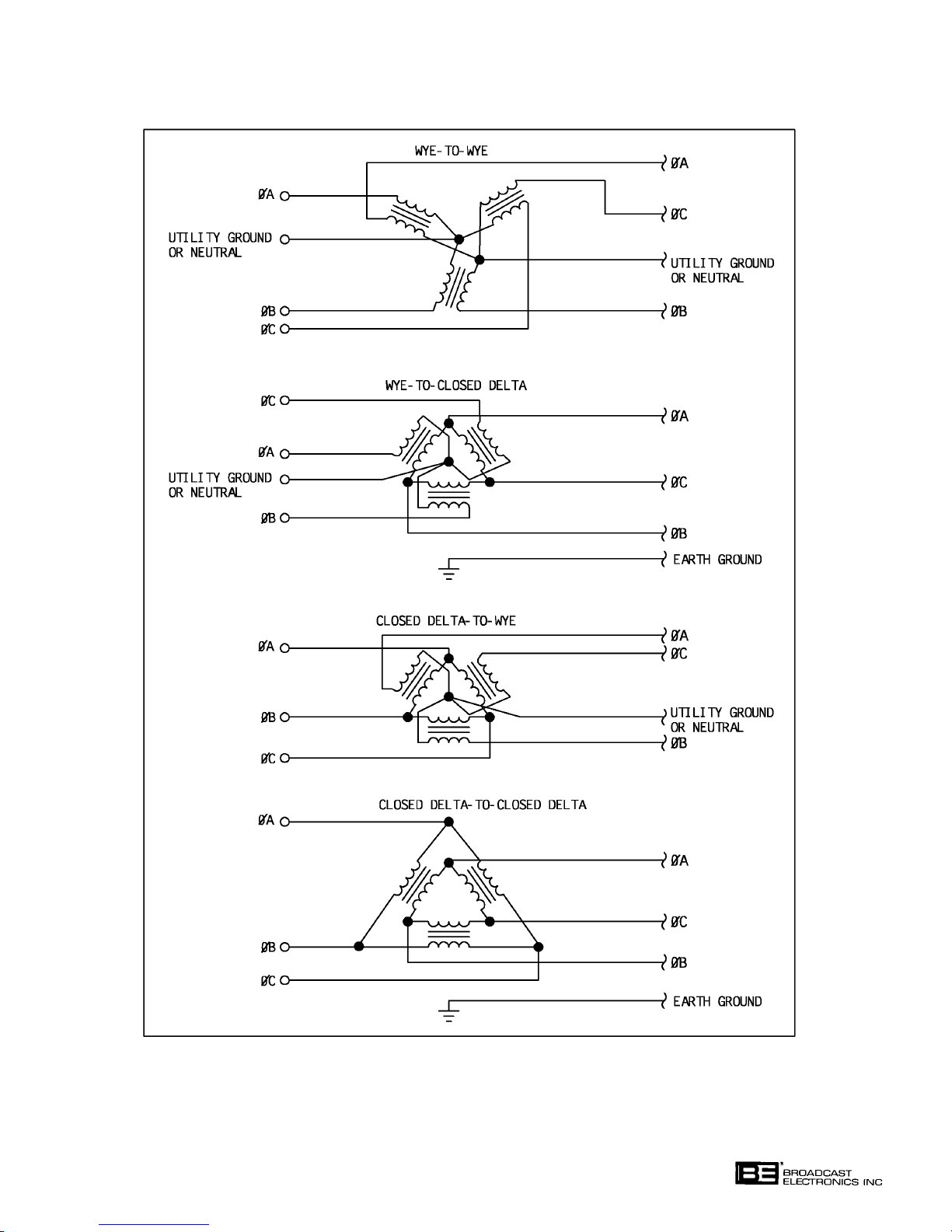
FIGURE 2-2. ACCEPTABLE AC POWER INPUT CONFIGURATIONS
COPYRIGHT 1997 BROADCAST ELECTRONICS, INC
597-0099-11
2-5
Page 22

2-28. Open the cavity access door.
2-29. Disconnect the plate line B+ banana plug along the right side of the plate line.
2-30. Remove all tape and shims from the plate line at the shelf to free the plate line. Raise and
rotate the plate line to lock the plate line in the up position.
2-31. Carefully remove all packing material from over the tube socket.
2-32. Carefully install the PA tube with a steady downward pressure. Do not rotate or rock the
tube during installation or the tube socket may be damaged.
2-33. After the PA tube is fully seated, rotate and lower the fixed portion of plate line over the
PA tube. Slowly lower the fixed portion of plate line down with both hands until the plate
line stops contact with the cavity shelf.
2-34. Reconnect the plate RF choke banana plug into the plate line and verify that the choke is
straight and perpendicular to the line with all connections secure. The plate line may be
rotated as required. The choke turns do not touch when properly aligned.
2-35. Secure the plate line to the tube with the strap clamp provided until the line does not slip
from the PA tube when upward pressure is applied. A flat-blade screwdriver with a 1/4
inch tip is required.
2-36. Close and latch the cavity access door.
2-37. On top of the cavity, loosen the PA tuning line clamp. A flat-blade screwdriver with a 1/4
inch (0.64 cm) tip is required.
2-38. Raise the PA tuning line until the scribed line is aligned with the top of the cavity clamp
ing flange. Ensure the tuning line is perpendicular to the top of the cabinet and secure the
strap clamp.
2-39. Ensure the coarse PA input tuning cyclometer on the rear of the PA input enclosure is set
to the value listed on the factory final test data sheets and the control is locked.
2-40. Remove the slide retainers from the exciter.
2-41. Loosen the exciter front-panel turn-lock fasteners and extend the unit forward.
2-42. Loosen the eight turn-lock fasteners on top of the exciter and remove the top cover.
2-43. Remove any packing material from the inside of the exciter.
2-44. Ensure the POS-MUTE-NEG switch on the power supply/control circuit board is oper
ated to POS.
2-45. Ensure the NORM-EXT switch is operated to NORM.
2-46. Refer to the final test data sheets shipped with the transmitter and ensure the AFC/PLL
assembly SYNTHESIZER FREQUENCY SELECTION switches are correctly positioned.
2-47. Replace the exciter top-panel.
2-48. Optional Equipment. If the transmitter is equipped with the optional LYNX stereo gen
erator and the FC-30 SCA generator, refer to the LYNX and FC-30 instruction manuals
and perform any unpacking and programming checks described in SECTION II, INSTAL
LATION.
2-49.
REMOTE CONTROL.
2-50. The FM-5T/FM-5TS transmitters are designed for complete remote control operations (re
fer to Figure 2-3). The transmitters will interface with almost any remote control unit
such as the Broadcast Electronics VMC-16 Voice Remote Control System. The following
text presents a description of the FM-5T/FM-5TS remote control functions and indica
tions. The remote control connections are located on the transmitter remote interface pan
el (refer to Figure 2-3).
2-6
Page 23
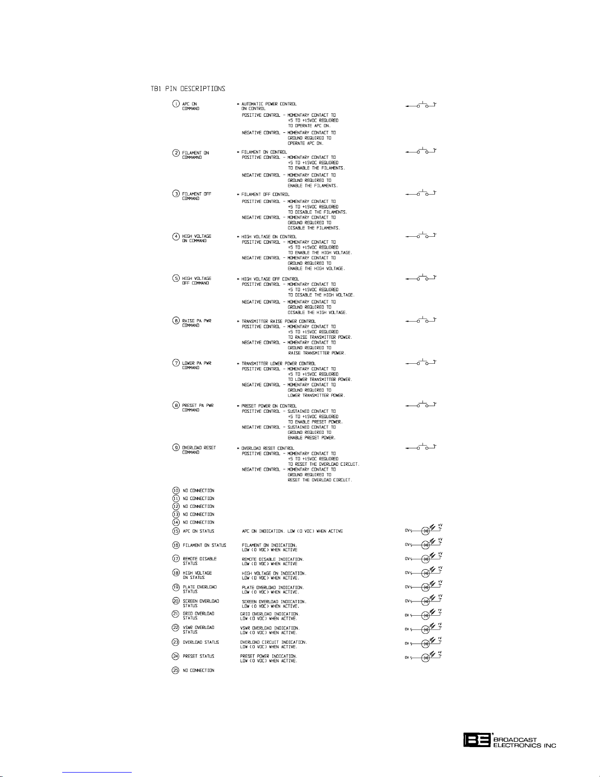
FIGURE 2-3. REMOTE CONTROL INTERFACING (SHEET 1 OF 2)
597-0220-418COPYRIGHT 1997 BROADCAST ELECTRONICS, INC
2-7
Page 24
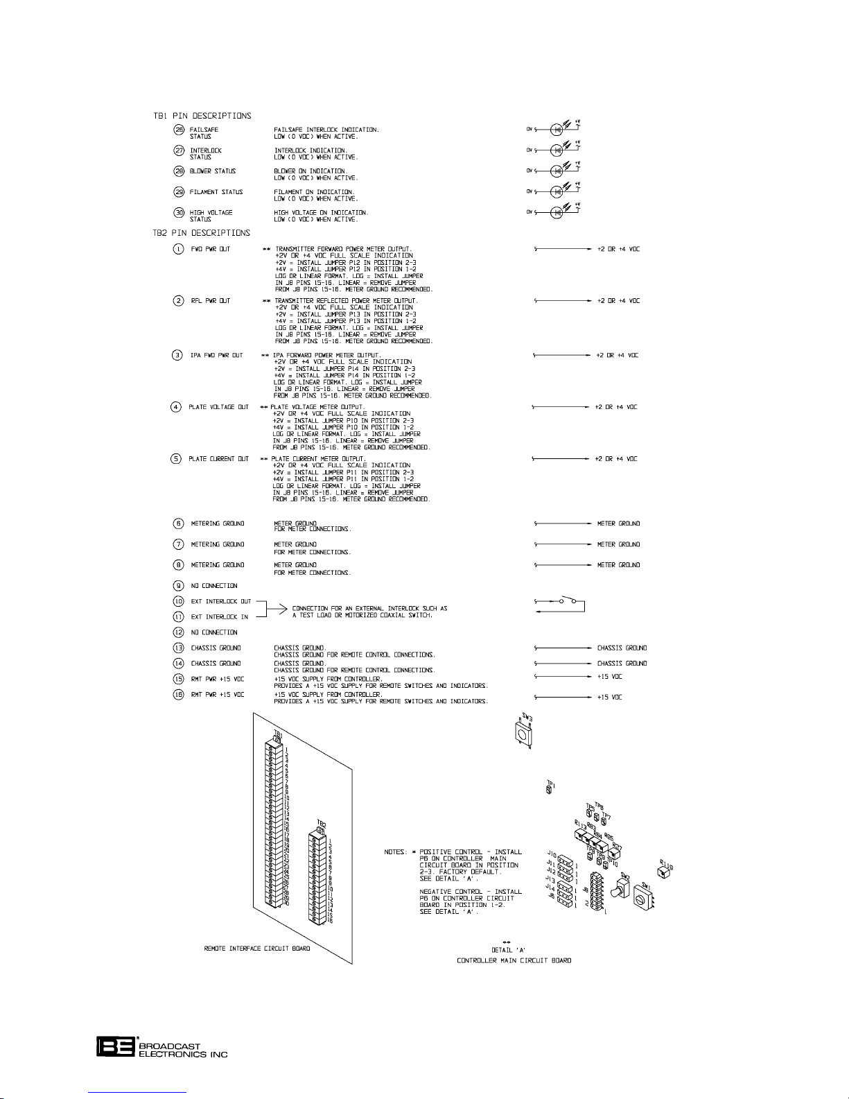
FIGURE 2-3. REMOTE CONTROL INTERFACING (SHEET 2 OF 2)
COPYRIGHT 1997 BROADCAST ELECTRONICS, INC
597-0220-418A
2-8
Page 25

2-51. The transmitter controller allows the selection of positive or negative control logic. Posi
tive/negative control is determined by header J6 on the controller main circuit board as
sembly. Positive control requires the use of a momentary contact to a +5 volt to +15 volt dc
signal to activate the function. Negative control requires the use of a momentary contact
to ground to activate the function. The transmitter controller is factory programmed for
positive remote control operations.
2-52. The remote meter outputs can be configured for: 1) +2/+4 volt dc full-scale indications and
2) a log or linear format. +2/+4 volt dc full-scale programming is determined by headers
J10 through J12 on the controller main circuit board. The log/linear control is determined
by header J8 pins 15-16 on the controller main circuit board. Refer to Figure 2-3 and the
following text to connect remote control equipment to the transmitter.
2-53. Remote APC On Control. The APC (automatic-power-control) on function is located at
TB1-1. The function can be activated using positive or negative control. Positive control
requires the use of a momentary contact to a +5 volt to +15 volt dc signal to enable APC
operation. Negative control requires the use of a momentary contact to ground to enable
APC operation.
2-54. Remote Filament On Control. The filament on function is located at TB1-2. The function
can be activated using positive or negative control. Positive control requires the use of a
momentary contact to a +5 volt to +15 volt dc signal to enable the filaments. Negative con
trol requires the use of a momentary contact to ground to enable the filaments.
2-55. Remote Filament Off Control. The filament off function is located at TB1-3. The function:
1) provides one-button-off control by disabling the high voltage and the filaments and
2) can be activated using positive or negative control. Positive control requires the use of a
momentary contact to a +5 volt to +15 volt dc signal to disable the: 1) filaments and
2) high voltage if not previously disabled. Negative control requires the use of a momen
tary contact to ground to disable the: 1) filaments and 2) high voltage if not previously dis
abled.
2-56. Remote High Voltage On Control. The high voltage on function is located at TB1-4. The
function: 1) provides one-button-on control by enabling the high voltage and the fila
ments and 2) can be activated using positive or negative control. Positive control requires
the use of a momentary contact to a +5 volt to +15 volt dc signal to enable the: 1) high volt
age and 2) filaments if not previously enabled. Negative control requires the use of a mo
mentary contact to ground to enable the: 1) high voltage and 2) filaments if not previously
enabled.
2-57. Remote High Voltage Off Control. The high voltage off function is located at TB1-5. The
function can be activated using positive or negative control. Positive control requires the
use of a momentary contact to a +5 volt to +15 volt dc signal to disable the high voltage.
Negative control requires the use of a momentary contact to ground to disable the high
voltage.
2-58. Remote PA Power Level Raise Control. The transmitter PA power level raise control is
located at TB1-6. The function can be activated using positive or negative control. Posi
tive control requires the use of a momentary contact to a +5 volt to +15 volt dc signal to
raise the transmitter power level. Negative control requires the use of a momentary con
tact to ground to raise the transmitter power level.
2-59. Remote Power Level Lower Control. The transmitter PA power level lower control is lo
cated at TB1-7. The function can be activated using positive or negative control. Positive
control requires the use of a momentary contact to a +5 volt to +15 volt dc signal to lower
the transmitter power level. Negative control requires the use of a momentary contact to
ground to lower the transmitter power level.
2-9
Page 26

2-60. Remote Preset Power On Control. The preset power on function is located at TB1-8. The
function can be activated using positive or negative control. Positive control requires the
use of a sustained contact to a +5 volt to +15 volt dc signal to enable preset power opera
tion. Negative control requires the use of a sustained contact to ground to enable preset
power operation. When a sustained remote control signal is applied, preset power will be
enabled if the APC switch/indicator is illuminated and the REMOTE DISABLE switch/in
dicator is extinguished. The transmitter will automatically return to full power when the
sustained remote control signal is removed.
2-61. Remote Overload Reset Control. The overload reset control is designed to reset the trans
mitter overload circuitry. The reset control is located at TB1-9. The function can be acti
vated using positive or negative control. Positive control requires the use of a momentary
contact to a +5 volt to +15 volt dc signal to reset the transmitter overload circuitry. Nega
tive control requires the use of a momentary contact to ground to reset the transmitter
overload circuitry.
2-62. No Connection. No connection at the following locations:
1) TB1-10 through TB1-14.
2) TB1-25.
3) TB2-9.
4) TB2-12.
2-63. APC On Indicator. The APC on indicator provides a signal to indicate when APC opera
tion is enabled. The APC on indicator is located at TB1-15. The indicator will go LOW (0
volts dc) to indicate when APC operation is enabled.
2-64. Filament On Indicator. The filament on indicator provides a signal to indicate when the
filaments are enabled. The filament on indicator is located at TB1-16. The indicator will
go LOW (0 volts dc) to indicate when the filaments are enabled.
2-65. Remote Disable Indicator. The remote disable indicator provides a signal to indicate
when the remote control inputs are disabled. The remote disable indicator is located at
TB1-17. The indicator will go LOW (0 volts dc) to indicate when the remote control inputs
are disabled.
2-66. Remote High Voltage On Indicator. The remote high voltage on indicator provides a sig
nal to indicate when the high voltage is enabled. The remote high voltage on indicator is
located at TB1-18. The indicator will go LOW (0 volts dc) to indicate when the high volt
age is enabled.
2-67. Remote Plate Overload Indicator. The remote plate overload indicator provides a signal
to indicate when a plate overload has occurred. The remote plate overload indicator is lo
cated at TB1-19. The indicator will go LOW (0 volts dc) to indicate when a plate overload
has occurred.
2-68. Remote Screen Overload Indicator. The remote screen overload indicator provides a sig
nal to indicate when a screen overload has occurred. The remote screen overload indicator
is located at TB1-20. The indicator will go LOW (0 volts dc) to indicate when a screen
overload has occurred.
2-69. Remote Grid Overload Indicator. The remote grid overload indicator provides a signal to
indicate when a grid overload has occurred. The remote grid overload indicator is located
at TB1-21. The indicator will go LOW (0 volts dc) to indicate when a grid overload has oc
curred.
2-70. Remote VSWR Overload Indicator. The remote VSWR overload indicator provides a sig
nal to indicate when a VSWR overload has occurred. The remote VSWR overload indicator
is located at TB1-22. The indicator will go LOW (0 volts dc) to indicate when a VSWR
overload has occurred.
2-10
Page 27

2-71. Remote Overload Indicator. The remote overload indicator provides a signal to indicate
when a plate, screen, grid, or VSWR overload has occurred. The remote overload indicator
is located at TB1-23. The indicator will go LOW (0 volts dc) to indicate when an overload
has occurred.
2-72. Remote Preset Power Indicator. The preset power indicator provides a signal to indicate
when preset power operation is enabled. The preset power indicator is located at TB1-24.
The indicator will go LOW (0 volts dc) to indicate when preset power operation is enabled.
2-73. Remote Failsafe Indicator. The failsafe indicator provides a signal to indicate when the
failsafe interlock is closed. The failsafe indicator is located at TB1-26. The indicator will
go LOW (0 volts dc) to indicate when the failsafe interlock is closed.
2-74. Remote Interlock Indicator. The interlock indicator provides a signal to indicate when the
internal interlock is closed. The interlock indicator is located at TB1-27. The indicator
will go LOW (0 volts dc) to indicate when the internal interlocks are closed.
2-75. Remote Blower Indicator. The blower indicator provides a signal to indicate when the
transmitter blower is operational. The blower indicator is located at TB1-28. The indica
tor will go LOW (0 volts dc) to indicate when the blower is operational.
2-76. Remote Filament Indicator. The filament indicator provides a signal to indicate when the
filament contactor is energized. The filament indicator is located at TB1-29. The indica
tor will go LOW (0 volts dc) to indicate when the filament contactor is energized.
2-77. Remote High Voltage Indicator. The high voltage indicator provides a signal to indicate
when the high voltage contactor is energized. The high voltage indicator is located at
TB1-30. The indicator will go LOW (0 volts dc) to indicate when the high voltage contactor
is energized.
2-78. Remote Forward Power Meter Indications. Remote forward power meter indications are
located at TB2-1. The forward power meter output can be configured for a +2 or +4 volt
dc full-scale meter indication. The forward power full-scale indication is 5500 watts. In
addition, the forward power sample can be provided in a log or linear format. The trans
mitter is shipped with the sample programmed for a linear format. The meter ground is
recommended for remote metering connections (TB2-6 through TB2-8).
2-79. Remote Reflected Power Meter Indications. Remote reflected power meter indications
are located at TB2-2. The reflected power meter output can be configured for a +2 or +4
volt dc full-scale meter indication. The reflected power full-scale indication is 1540 watts.
In addition, the reflected power sample can be provided in a log or linear format. The
transmitter is shipped with the sample programmed for a linear format. The meter ground
is recommended for remote metering connections (TB2-6 through TB2-8).
2-80. Remote Plate Voltage Meter Indications. Remote plate voltage meter indications are lo
cated at TB2-4. The plate voltage meter output can be configured for a +2 or +4 volt dc
full-scale meter indication. The plate voltage full-scale indication is 6000 volts. In addi
tion, the plate voltage sample can be provided in a log or linear format. The transmitter is
shipped with the sample programmed for a linear format. The meter ground is recom
mended for remote metering connections (TB2-6 through TB2-8).
2-81. Remote Plate Current Meter Indications. Remote plate current meter indications are lo
cated at TB2-5. The plate current meter output can be configured for a +2 or +4 volt dc
full-scale meter indication. The plate current full-scale indication is 1.5 amps. In addi
tion, the plate current sample can be provided in a log or linear format. The transmitter is
shipped with the sample programmed for a linear format. The meter ground is recom
mended for remote metering connections (TB2-6 through TB2-8).
2-82. Remote IPA Forward Power Meter Indications. Not used in FM-5T/FM-5TS.
2-83. Chassis Ground. Chassis ground is designed to be used for remote control connections.
Chassis ground is located at TB2-13 and TB2-14.
2-84. +15V DC Supply. A +15 volt dc supply is provided for the remote control switches and in
dicators. The +15 volt dc supply is located at TB2-15 and TB2-16.
2-11
Page 28

2-85. WIRING.
WARNING
ENSURE PRIMARY POWER IS DISCONNECTED BE
FORE PROCEEDING.
WARNING
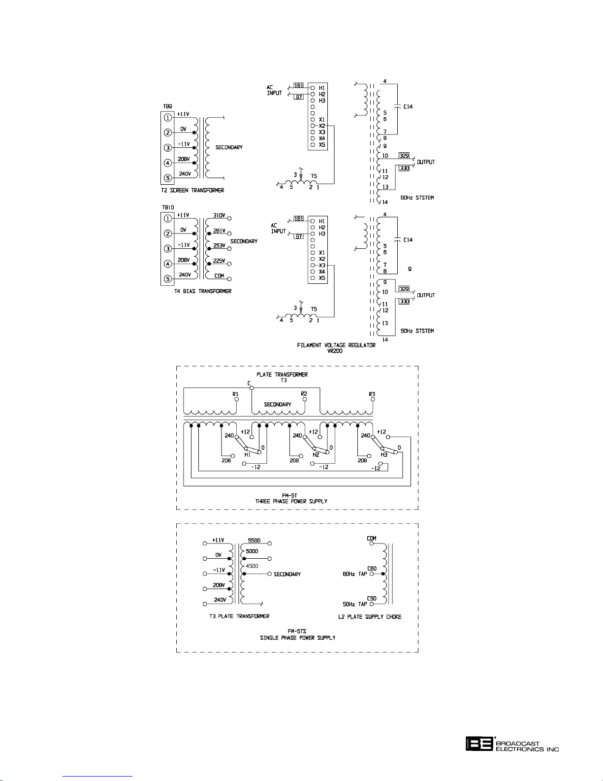
2-86. TRANSFORMER TAPS. Ensure that the transmitter is wired for the input voltage and line
frequency to be used. The screen transformer, the plate transformer, the bias transformer,
the filament regulator, and the plate supply choke must be checked and changed if re
quired. Refer to Figure 2-4 and the final test data sheets for transformer tap information.
2-87. INPUT VOLTAGE CHECK. The FM exciter, stereo generator, and SCA generator should be
checked as follows:
A. The primary ac line voltage with which the transmitter will be used (220V or
230/240V) must be visible on the ac line voltage selector circuit board located
adjacent to the ac input connector on each unit.
B. If an ac line voltage selector must be changed, remove the ac line voltage selector
circuit board with a small pair of needle-nose pliers. Reinsert the circuit board so
that the correct ac line voltage is visible when the circuit board is reinserted into
the receptacle.
WARNING
ENSURE PRIMARY POWER IS DISCONNECTED BE
FORE PROCEEDING.
WARNING
CAUTION
THE AC DISTRIBUTION PANEL PROVIDES A 220V AC
OPERATING SUPPLY FOR OPTIONAL EQUIPMENT.
CAUTION
ENSURE ALL 220V AC AND 110V AC EQUIPMENT IS
PROPERLY CONNECTED TO THE PANEL.
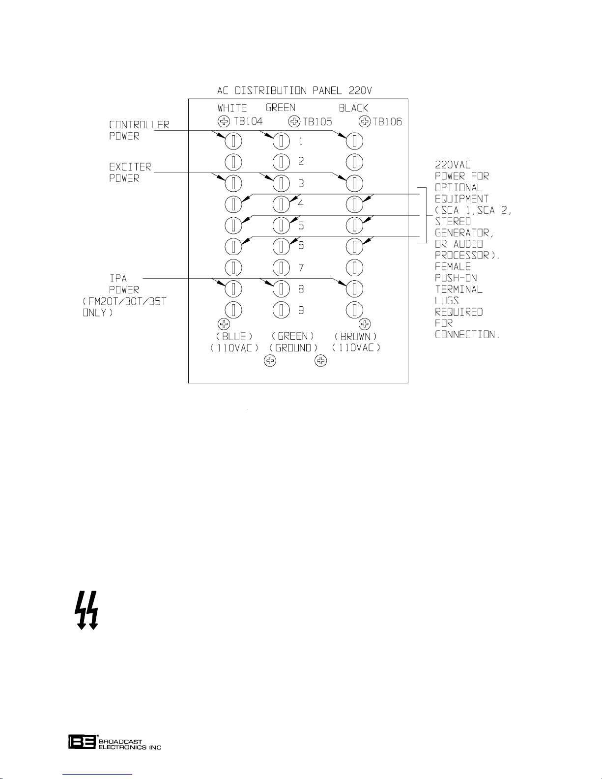
2-88. OPTIONAL EQUIPMENT WIRING. An ac distribution panel is provided for the application
of ac power to the transmitter modular components. Mount and wire any optional equip
ment not provided with the transmitter to the distribution panel (refer to Figure 2-5). The
ac distribution panel provides a 220V ac operating supply for the optional equipment. En
sure all 220V ac and 110V ac equipment is properly connected to the panel.
SIGNAL INPUTS. Refer to the applicable technical manual for the exciter, stereo genera
2-89.
tor, and SCA generator and wire the inputs and control connections to each unit. All audio
wiring must be routed in the wiring channel away from the power supply components in
the base.
2-90.
FAILSAFE INTERLOCK. The FM-5T/FM-5TS transmitters are equipped with a failsafe
interlock circuit such as for a test load or remote control failsafe connection. The failsafe
interlock circuit is independent of the transmitter safety interlock circuit and will disable
only the high voltage plate supply when opened. The interlock is located at TB2-10 and
TB2-11 on the transmitter remote interface panel. Refer to Figure 2-3 and connect the
interlock wiring to TB2-10 and TB2-11 as shown. If unused, ensure the factory installed
jumper is connected between the terminals.
2-12
Page 29
COPYRIGHT 1997 BROADCAST ELECTRONICS, INC
597-0033-415
FIGURE 2-4. TRANSFORMER TAPS
2-13
Page 30
COPYRIGHT 1997 BROADCAST ELECTRONICS, INC
FIGURE 2-5. OPTIONAL EQUIPMENT WIRING
597-0220-403
2-91. TRANSMITTER MONITORING - MODEM CONNECTIONS. The FM-5T/FM-5TS trans
mitters are equipped with: 1) a built-in front-panel modem port and 2) a built-in
rear-panel modem port. The modem ports allow modems to be connected to the transmit
ter for local and remote monitoring of transmitter parameters using a future local/remote
diagnostic system.
2-92.
TRANSMITTER MONITORING - PRINTER CONNECTIONS. The FM-5/FM-5TS trans
mitters are equipped with a built-in printer port. The printer port allows transmitter pa
rameters to be printed using a local printer and a future local/remote diagnostic system.
WARNING
ENSURE PRIMARY POWER IS DISCONNECTED BE
FORE PROCEEDING.
WARNING
2-93. AC POWER CONNECTIONS. The following text presents three phase ac power connec
tions for an FM-5T transmitter and single phase ac power connections for an FM-5TS
transmitter. Refer to the following information and connect the FM-5T/FM-5TS transmit
ters to the appropriate power supply.
2-14
Page 31

WARNING
WARNING
ENSURE PRIMARY POWER IS DISCONNECTED BE
FORE PROCEEDING.
WARNING
ENSURE AN EARTH GROUND CONDUCTOR IS SE
CURELY CONNECTED TO THE TRANSMITTER
WARNING
2-94. FM-5T. A three phase source of 196V to 252V ac 50 Hz or 60 Hz or 341 to 435V ac 50 Hz at
40 Amperes per phase is required for the FM-5T transmitter ac input. Ensure the power
source is supplied from an acceptable ac transformer configuration (refer to PRIMARY AC
POWER). For operating safety, the power source must be routed to the transmitter
through a fused power disconnect (refer to Figure 2-6).
2-95. Refer to Figure 2-6 and connect the 40 Ampere three phase service to TB1 on the trans
mitter base-plate through a fused service disconnect. Ensure a utility company ground
conductor is securely connected to the transmitter ground system. For a three phase 380V
WYE service, ensure the neutral wire is connected to ac input terminal TB1-4.
WARNING
GROUND SYSTEM.
ENSURE PRIMARY POWER IS DISCONNECTED BE
FORE PROCEEDING.
WARNING
WARNING
ENSURE AN EARTH GROUND CONDUCTOR IS SE
CURELY CONNECTED TO THE TRANSMITTER
WARNING
2-96. FM-5TS. A single phase source of 196V to 252V ac, 50 or 60 Hz at 70 Amperes is required
for the FM-5TS transmitter ac input. For operating safety, the power source must be
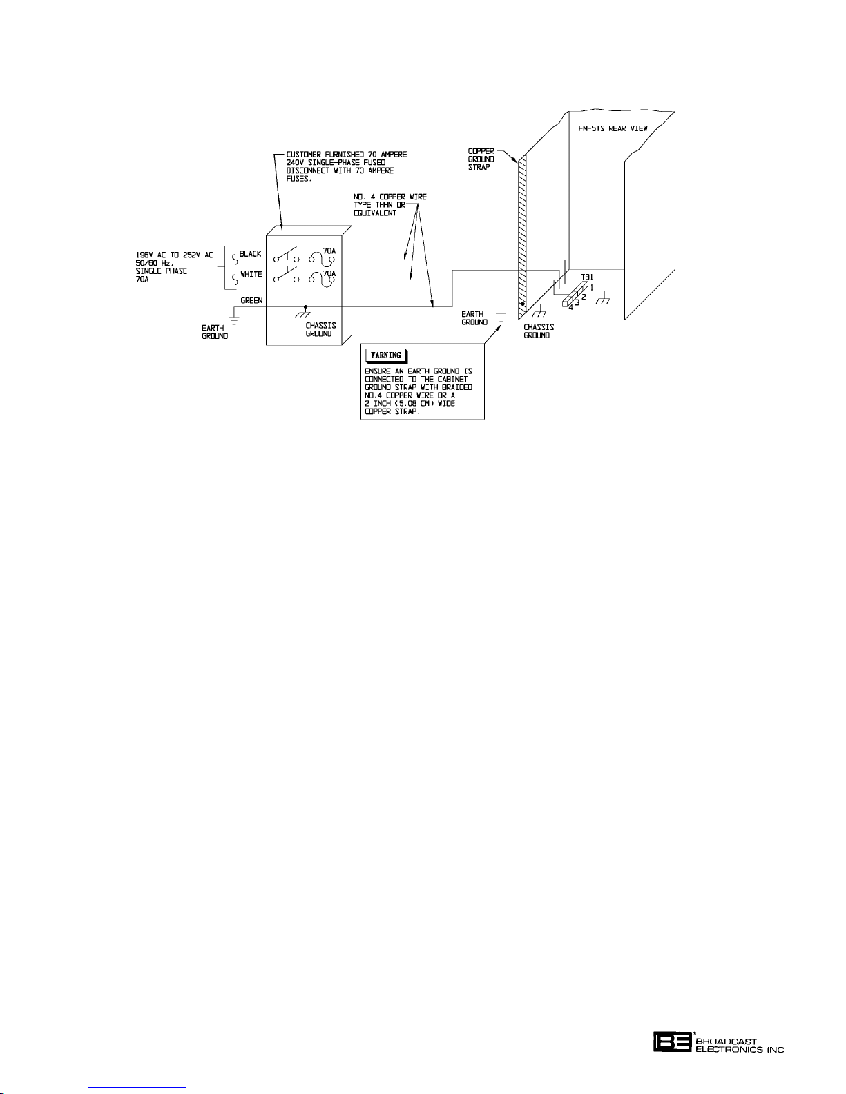
routed to the transmitter through a fused power disconnect (refer to Figure 2-7).
2-97. Refer to Figure 2-7 and connect the 70 Ampere service to TB1 on the transmitter base-
plate through a fused service disconnect. Ensure a utility company ground conductor is
securely connected to the transmitter ground system and the neutral wire is securely con
nected to TB1-2.
2-98.
INITIAL CHECKOUT.
GROUND SYSTEM.
WARNING
WARNING
2-99. Ensure that the transmitter is completely installed, the transmitter is connected to a suit
able RF load, and the station monitors are connected to the MON port in the RF low-pass
filter output. The MON port provides a harmonic-filtered RF sample which is approxi
mately 40 dB below the carrier power level. Check the following:
A. Ensure primary power is correctly wired.
B. Ensure all ground connections are secure.
C. Ensure all RF connections are secure.
D. Ensure all connections at terminal boards are secure.
E. Rotate the blower and fans by hand to ensure no obstructions are present.
F. Using an insulator, check relay operation manually to be certain all have free
movement.
ENSURE PRIMARY POWER IS DISCONNECTED BE
FORE PROCEEDING.
2-15
Page 32
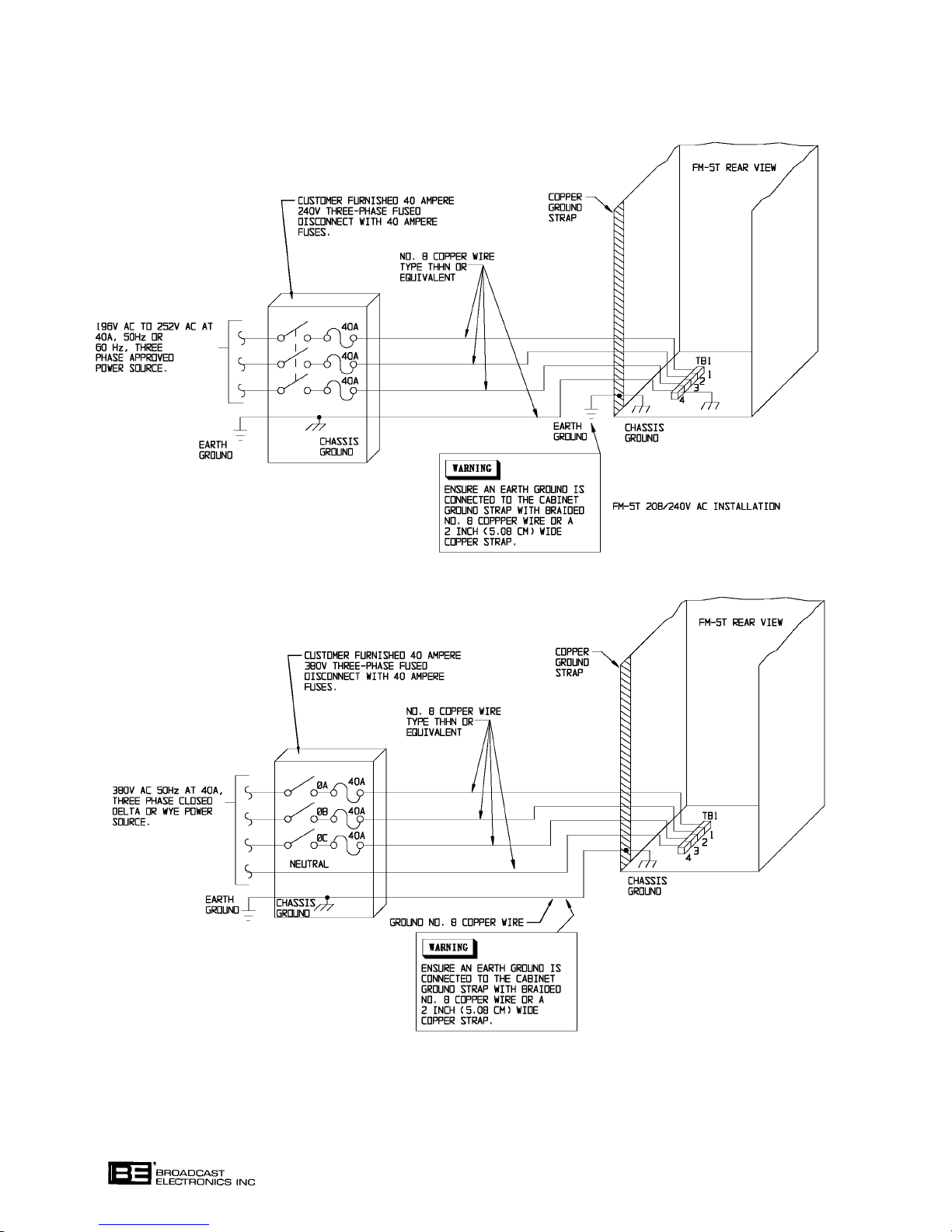
FIGURE 2-6. FM-5T PRIMARY AC WIRING
COPYRIGHT 1997 BROADCAST ELECTRONICS, INC
597-0033-406
2-16
Page 33
COPYRIGHT 1997 BROADCAST ELECTRONICS, INC
FIGURE 2-7. FM-5TS PRIMARY AC WIRING
597-0033-407
2-100. Remove any extra hardware and wire lying within the cabinets and close all doors. Re
place the lower front access panel using the black hex-head screws and hex wrench
shipped with the transmitter.
2-101. Adjust the FILAMENT ADJUST control fully counterclockwise (minimum).
2-102. Operate all five front-panel circuit breakers to OFF.
2-103. Close the wall-mounted fused disconnect.
2-104. Extend the exciter forward, out of the rack on the slide rails to expose the R.F. POWER
OUTPUT ADJ. control access hole in the top cover. Adjust the control fully counterclock
wise (minimum output).
2-105. The following procedure will refer to the factory final test data sheets supplied with the
transmitter. Some differences in the actual operation may be noted due to differences in
primary power or antenna systems. Ensure all controls are preset to the positions indi
cated on the final test data sheets.
2-106.
CONTROLLER AND INTERLOCK CHECKOUT. Check the controller and the transmitter
interlock circuit by performing the following procedure.
2-107. Operate the AC POWER and the BLOWER circuit breakers to ON. The FILAMENT
and SCREEN circuit breakers must remain OFF.
2-108. Open the controller cabinet door and check the following items on the main circuit board.
A. Ensure the -15 indicator is illuminated.
B. Ensure the +15 indicator is illuminated.
C. Ensure the +5 indicator is illuminated.
2-17
Page 34

WARNING
PERFORM THE FOLLOWING PROCEDURES AS INDI
CATED. DO NOT TOUCH ANYTHING WITHIN THE
WARNING
2-109. Remove the transmitter lower front access panel. The controller TRANSMITTER STA
TUS INTERLOCK indicator will extinguish.
2-110. Replace the transmitter lower front access panel. The controller TRANSMITTER STA
TUS INTERLOCK indicator will illuminate.
2-111. Open the transmitter rear door. The controller TRANSMITTER STATUS INTERLOCK
indicator will extinguish.
2-112. Close the transmitter rear door. The controller TRANSMITTER STATUS INTERLOCK
indicator will illuminate.
2-113. Open the transmitter rear door and perform the following:
TRANSMITTER WITH POWER ENERGIZED.
WARNING
PERFORM THE FOLLOWING PROCEDURES AS INDI
CATED. DO NOT TOUCH ANYTHING WITHIN THE
WARNING
A. Depress the transmitter rear door interlock switch and raise the grounding stick
from the hanger. The controller TRANSMITTER STATUS INTERLOCK
indicator will extinguish.
B. Replace the grounding stick. The controller TRANSMITTER STATUS
INTERLOCK indicator will illuminate.
C. While depressing the transmitter rear door interlock switch, open the PA cavity ac-
cess door. The controller TRANSMITTER STATUS INTERLOCK indicator will
extinguish.
D. Close the PA cavity access door. The controller TRANSMITTER STATUS
INTERLOCK indicator will illuminate.
E. Close the transmitter rear door.
2-114. If equipment is connected to the failsafe interlock circuit, check the operation as follows:
A. Open the failsafe interlock. The controller TRANSMITTER STATUS
INTERLOCK indicator will extinguish.
B. Close the failsafe interlock. The controller TRANSMITTER STATUS
INTERLOCK indicator will illuminate.
2-115.
2-116. Ensure the AC POWER and BLOWER circuit breakers are operated to ON. The FILA
2-117. Depress the FILAMENT ON switch/indicator to illuminate the switch/indicator. The
2-118. Ensure the blower, TRANSMITTER STATUS BLOWER indicator, and the TRANSMIT
BLOWER CHECKOUT. Check blower operation by performing the following procedure.
MENT and SCREEN circuit breakers must remain OFF.
FILAMENT ON switch/indicator, TRANSMITTER STATUS BLOWER, and the
TRANSMITTER STATUS FILAMENT indicators will illuminate and the blower will be
gin operation.
TER STATUS FILAMENT indicator are operating properly. At high altitudes, the
TRANSMITTER STATUS BLOWER indicator may not illuminate. If this occurs, con
tact the Broadcast Electronics Customer Service Department.
TRANSMITTER WITH POWER ENERGIZED.
2-18
Page 35

2-119. EXCITER CHECKOUT. Check exciter operation by performing the following procedure.
2-120. Ensure the AC POWER and BLOWER circuit breakers are operated to ON. The
SCREEN and FILAMENT circuit breakers must remain OFF.
2-121. Depress the HIGH VOLTAGE ON switch/indicator to illuminate the switch/indicator.
2-122. Depress the exciter multimeter AFC switch.
A. The multimeter will indicate a potential within the range of +2.0 volts to +9.0 volts,
dependent upon carrier frequency. Refer to the final test data sheets for the correct
voltage indication.
2-123. Depress the exciter multimeter PAV switch.
A. The multimeter will indicate a potential of approximately +0.0 volts to 0.5 volts
(assuming the exciter is configured for a minimum RF power output).
2-124. Depress the exciter multimeter PAI switch.
A. The multimeter will indicate approximately 0.0 amperes (assuming the exciter is
configured for a minimum RF power output).
2-125. Depress the FILAMENT OFF switch.
2-126.
PRELIMINARY OPERATION AND TUNING. Operate and tune the transmitter by per
forming the following procedure.
2-127. Ensure the AC POWER and BLOWER circuit breakers are operated to ON. The
SCREEN and FILAMENT circuit breakers must remain OFF.
2-128. Ensure the controller TRANSMITTER STATUS INTERLOCK indicator is illuminated.
If the indicator is extinguished, open the wall-mounted fused disconnect and check the fol
lowing:
A. All panels are installed.
B. All shorting sticks are on the hangers.
C. All doors are closed.
2-129. If equipment is connected to the failsafe interlock, ensure the controller TRANSMITTER
STATUS FAILSAFE indicator is illuminated. If the indicator is extinguished, open an
appropriate power source disconnect if required and check the interlock switch.
2-130. Ensure the FILAMENT ON and HIGH VOLTAGE ON switch/indicators are extin
guished.
2-131. Ensure the exciter RF OUTPUT POWER ADJ control is fully counterclockwise (mini
mum).
2-132. Depress the controller APC ON switch/indicator to extinguish the switch/indicator.
2-133. Depress the controller REMOTE DISABLE switch/indicator to illuminate the
switch/indicator.
2-134. Depress the controller FWD switch/indicator to illuminate the switch/indicator.
2-19
Page 36

CAUTION
ENSURE AN RF LOAD IS CONNECTED TO THE TRANS
MITTER AND THE FILAMENT VOLTAGE CONTROL IS
CAUTION
2-135. Operate the FILAMENT circuit breaker to ON.
2-136. Depress the FILAMENT ON switch/indicator. Both the FILAMENT ON switch/indicator
and the FILAMENT TRANSMITTER STATUS indicator will illuminate and the blower
will begin operation.
2-137. Adjust the FILAMENT ADJUST control to obtain a FILAMENT VOLTAGE meter indi
cation of 5.0 volts.
2-138. Operate the MULTIMETER switch to GRID VOLTAGE and note the presence of PA
stage grid bias without drive.
2-139. Operate the SCREEN circuit breaker to ON.
2-140. Depress the HIGH VOLTAGE ON switch/indicator. Both the HIGH VOLTAGE ON
switch/indicator and the HIGH VOLTAGE TRANSMITTER STATUS indicator will illu
minate.
2-141. Note the presence of plate voltage on the PLATE VOLTAGE meter.
2-142. If equipment is connected to the failsafe interlock, check the external interlock operation
as follows:
ADJUSTED TO APPROXIMATELY MID-RANGE.
WARNING
OBSERVE PROPER SAFETY PRECAUTIONS WHEN
PERFORMING THE FOLLOWING PROCEDURE.
WARNING
A. Open the failsafe interlock. The controller FAILSAFE TRANSMITTER STATUS
and the HIGH VOLTAGE TRANSMITTER STATUS indicators will extinguish
and the high voltage plate supply will be disabled.
B. Close the failsafe interlock. The plate supply will be restored, the transmitter will
resume operation, and the controller FAILSAFE TRANSMITTER STATUS
and the HIGH VOLTAGE TRANSMITTER STATUS indicators will illuminate.
2-143. Adjust the exciter RF POWER OUTPUT ADJ control to obtain approximately five watts
from the exciter.
2-144. Depress the exciter multimeter PAV switch.
A. The multimeter will indicate a potential within the range of +0.0 volts to +0.5 volts
(assuming an RF output power of 1 watt).
2-145. Depress the exciter multimeter PAI switch.
A. The multimeter will indicate approximately 0.0 amperes (assuming RF output
power of 1 watt).
2-146. Depress the exciter multimeter FWD switch.
2-147. Operate the MULTIMETER switch to EXCITER RFL POWER and adjust the INPUT
TUNING control to obtain a minimum reflected power indication on the MULTIMETER.
2-20
Page 37

CAUTION
CHECK THE TRANSMITTER OUTPUT POWER INDICA
TION TO ENSURE TRANSMITTER OUTPUT POWER IS
CAUTION
2-148. Note the presence of output power on the OUTPUT POWER meter. If no output power is
indicated, perform the following:
1. Ensure the PA coarse tuning line is properly adjusted.
2. Adjust the OUTPUT TUNING control for a maximum indication on the OUTPUT
POWER meter.
2-149. Adjust the exciter output to approximately 90 watts.
2-150. The FM-250C VSWR indicator illuminates during the remainder of the initial checkout
procedure, this indicates that the IPA load is incorrect. To correct the situation, operate
the MULTIMETER switch to EXCITER RFL POWER and re-adjust the INPUT TUN
ING control for a minimum reflected power indication on the FM-250C.
2-151. The OUTPUT POWER and PLATE CURRENT meters will indicate a low level of less
than 20% full-scale.
2-152. Adjust the OUTPUT TUNING and OUTPUT LOADING controls for a maximum OUT
PUT POWER meter indication.
2-153. Depress the controller RAISE switch/indicator until a 400 mA PLATE CURRENT meter
indication is noted.
PRESENT.
2-154. Adjust the OUTPUT TUNING and OUTPUT LOADING controls for a maximum OUT
PUT POWER meter indication.
2-155. Operate the MULTIMETER switch to EXCITER RFL POWER and adjust the INPUT
TUNING control to obtain a minimum reflected power indication on the MULTIMETER.
2-156. Depress the controller RAISE switch/indicator until a 50% indication is obtained on the
OUTPUT POWER meter.
2-157. Depress the controller VSWR switch/indicator to illuminate the switch/indicator.
2-158. The OUTPUT POWER meter must indicate a VSWR of less than 1.8:1. An excessive
VSWR indicates improper load connections.
2-159. Depress the controller FWD switch/indicator to illuminate the switch/indicator.
2-160. Adjust the OUTPUT TUNING and OUTPUT LOADING controls for maximum indica
tion on the OUTPUT POWER meter, concurrent with a minimum indication on the
PLATE CURRENT meter.
2-161. Adjust the exciter RF OUTPUT POWER ADJ control to the value stated on the factory
test data sheets.
2-162. Operate the MULTIMETER switch to EXCITER RFL POWER and adjust the INPUT
TUNING control to obtain a minimum reflected power indication on the MULTIMETER.
2-163. Depress the controller RAISE switch/indicator. Continue to depress the switch/indicator
until a 100% power indication is noted on the OUTPUT POWER meter. If a plate or
screen current overload occurs, it may be necessary to adjust the OUTPUT LOADING for
better efficiency before increasing power to 100%.
2-164. Operate the MULTIMETER switch to EXCITER RFL POWER and adjust the INPUT
TUNING control to obtain a minimum reflected power indication on the MULTIMETER.
2-21
Page 38

2-165. Adjust the OUTPUT LOADING and OUTPUT TUNING controls to obtain the values
stated on the factory test data sheets.
2-166. Check the FILAMENT VOLTAGE meter and adjust the FILAMENT ADJUST control as
required. The meter must indicate 5 volts.
2-167. Adjust the PA stage for the most efficient operation by adjusting the OUTPUT TUNING
and OUTPUT LOADING controls for a maximum indication on the OUTPUT POWER
meter concurrent with a minimum indication on the PLATE CURRENT meter.
2-168. Operate the MULTIMETER to EXCITER RFL POWER and adjust the INPUT TUN
ING control for a minimum reflected power indication.
2-169. Depress the controller RAISE or LOWER switch/indicators as required to obtain a 100%
OUTPUT POWER METER indication.
2-170. Compare the meter indications to those provided on the final test data sheets. All meter
indications should be approximately the same as those stated on the final test data sheets.
2-171. Depress the APC ON switch/indicator. The switch/indicator will illuminate and the trans
mitter will maintain a constant 100% rated RF output.
2-172. Apply programming to the exciter. The presence of programming may be noted on the ex
citer MODULATION meter.
2-173. To adjust the automatic power control unit to maintain a level other than 100%, the APC
ON switch/indicator must be illuminated. Depress either the RAISE or the LOWER
switch/indicator as desired until the desired percentage of transmitter power output is in
dicated by the OUTPUT POWER meter. The automatic power control circuitry operates
in small increments and will take some time to track the reference to the new set point.
The automatic power control circuitry will then maintain this new established RF output
level.
2-174. If remote operation is desired, the REMOTE DISABLE switch/indicator must be extin
guished. TB1-17 on the remote interface circuit board provides a signal which can be con
nected to a relay or logic circuit to control a light or alarm to remind the engineer of the
status of the remote disable switch. This feature will hopefully prevent inadvertent remote
lockout if the engineer should leave the transmitter site and forget to enable remote opera
tion.
2-22
Page 39

SECTION III
OPERATION
3-1. INTRODUCTION.
3-2. This section identifies all controls and indicators associated with the FM-5T/FM-5TS FM
transmitters and provides standard operating procedures.
3-3. CONTROLS AND INDICATORS.
3-4. Refer to Figure 3-1 for the location of all controls and indicators associated with normal
operation of the FM-5T/FM-5TS transmitters. The function of each control or indicator is
described in Table 3-1.
3-5.
OPERATION.
NOTE
THE FOLLOWING PROCEDURE IS PRESENTED UN
DER THE ASSUMPTION THAT THE TRANSMITTER IS
NOTE
FULLY INSTALLED AND IS FREE OF ANY DISCREPAN
CIES.
3-6. TURN ON.
3-7. Operate all circuit breakers to ON.
3-8. Depress the REMOTE DISABLE switch/indicator to illuminate the switch/indicator.
3-9. Depress the FILAMENT ON switch/indicator, then depress the HIGH VOLTAGE ON
switch/indicator. Each switch/indicator will illuminate as it is depressed.
3-10. If all interlocks are closed, the transmitter will be operational after a short delay to allow
PA tube filament warm-up.
3-11. Check and log all meter indications and the status of the various indicators to assure prop
er equipment operation. A sample log sheet is provided as Table 3-2.
3-12. Depress the FWD switch/indicator to illuminate the switch/indicator and check the for
ward power output.
NOTE
THE VSWR METER IS MOST ACCURATE WHEN THE
TRANSMITTER IS OPERATED AT 100% (NORMAL TPO)
NOTE
POWER. TRANSMITTER OPERATION AT A REDUCED
POWER LEVEL WILL RESULT IN REDUCED VSWR
METER ACCURACY.
3-13. Depress the VSWR switch/indicator to illuminate the switch/indicator and check the
VSWR.
3-14. Select the type of RF output power control:
A. If manual power control is desired, proceed as follows:
1. Depress the APC ON switch/indicator to extinguish the switch/indicator.
2. Depress the RAISE or LOWER switch/indicator to raise or lower the
transmitter RF output power as indicated by the OUTPUT POWER meter.
3-1
Page 40

B. If automatic power control is desired, depress the APC ON switch/indicator to
illuminate the switch/indicator. To adjust the level at which the automatic power
control circuitry will maintain, proceed as follows:
1. Depress the APC ON switch/indicator to illuminate the switch/indicator.
2. Depress the RAISE or LOWER switch/indicator to establish a new RF power
output level as indicated by the OUTPUT POWER meter.
3-15. If remote operation is desired, depress the REMOTE DISABLE switch/indicator to extin
guish the switch/indicator. This will enable both local and remote operation.
3-16.
3-17. Depress the FILAMENT OFF switch/indicator. After a period of blower operation to allow
3-18. Operate the AC POWER circuit breaker to OFF.
3-19. OPERATING THE TRANSMITTER FOR MAXIMUM TUBE LIFE.
3-20. The FM-5T/FM-5TS is equipped with an Eimac 4CX3500A tetrode. Maximum tube life is
TURN OFF.
the PA tube to cool, the equipment will de-energize.
obtained by the implementation of a tube management program. A tube management pro
gram consists of operating and monitoring the transmitter to maintain an optimum tube
filament voltage. This optimum voltage prevents premature de-carbonization of the tube
filament and will result in maximum tube life. To maximize transmitter tube life, imple
ment the procedures and operations presented in the following tube management program.
TUBE MANAGEMENT PROGRAM
1) Refer to APPENDIX A and perform the procedures presented in the Eimac
publication titled Extending Transmitter Tube Life - Eimac Application Bulletin
No. 18. - March 1990".
2) Refer to APPENDIX A and the information presented in Eimac Technical Data
Sheet - 4CX3500A Tetrode".
3) The procedures presented in any Eimac Product Bulletins" shipped with the tube.
3-21. CONTINUOUSLY FLASHING CONTROLLER SWITCH/INDICATOR.
3-22. The FM-5T/FM-5TS controller is equipped with an automatic remote/local control trouble
shooting feature. This feature can determine if a remote control or a front-panel control is
being continuously held in operation by a device such as a defective remote control unit. If
a control is continuously held in operation, the front-panel switch/indicator will flash. If
this condition occurs, contact the Broadcast Electronics RF Customer Service Department.
TABLE 3-1. FM-5T/FM-5TS PA/DRIVER CABINET CONTROLS AND INDICATORS
INDEX
NO. NOMENCLATURE FUNCTION
1 VSWR OVERLOAD Indicates a PA stage VSWR overload has occurred
2 PLATE OVERLOAD Indicates a PA plate circuit overload has occurred when
Indicator illuminated.
(Sheet 1 of 5)
when Indicator illuminated.
3-2
Page 41
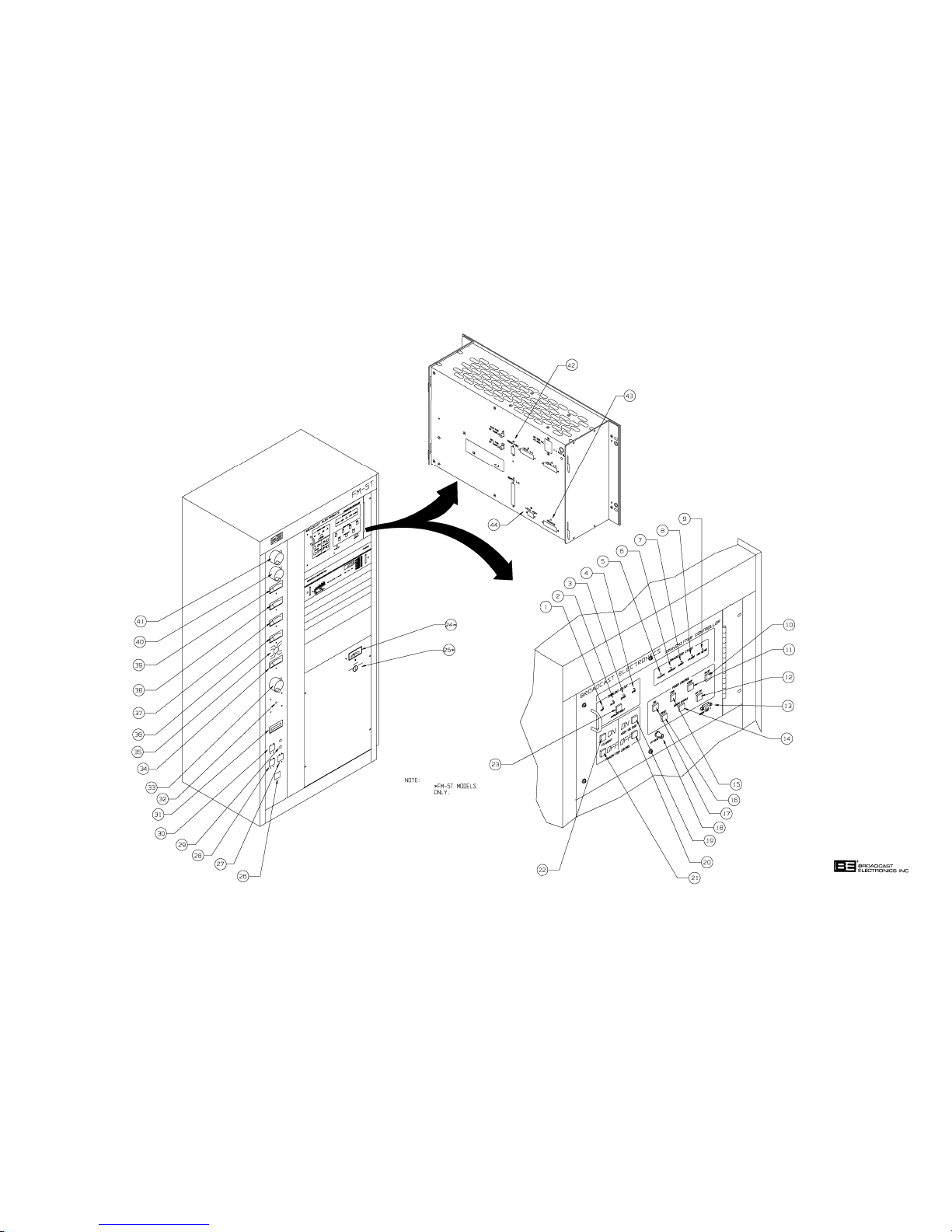
597-0033-408
FIGURE 3-1. CONTROLS AND INDICATORS
(3-3/3-4)
COPYRIGHT 1997 BROADCAST ELECTRONICS, INC
Page 42

TABLE 3-1. FM-5T/FM-5TS PA/DRIVER CABINET CONTROLS AND INDICATORS
(Sheet 2 of 5)
INDEX
NO. NOMENCLATURE FUNCTION
3 SCREEN OVERLOAD Indicates a PA screen circuit overload has occurred
Indicator when illuminated.
4 GRID OVERLOAD Indicates a PA grid power supply overload has occurred
Indicator when illuminated.
5 FAILSAFE STATUS Indicates the failsafe interlock is closed when illumi-
Indicator nated.
6 INTERLOCK STATUS Indicates all transmitter internal interlocks are closed
Indicator when illuminated.
7 BLOWER STATUS Indicates proper operation of the blower when illuminated.
Indicator
8 FILAMENT STATUS Indicates primary ac power is applied to the PA filament
Indicator regulator when illuminated.
9 HIGH VOLTAGE Indicates the plate power supply is operational when
STATUS Indicator illuminated.
10 POWER CONTROL SWITCH: In the automatic mode, moves the APC
RAISE reference upward when depressed. In the
Switch/Indicator manual mode, operates the screen control
motor in a direction which will raise trans-
mitter RF output power when depressed.
INDICATOR: Illuminates to indicate the screen control
motor is operating in a direction which will
raise the transmitter RF power output.
11 POWER CONTROL SWITCH: In the automatic mode, moves the APC
LOWER reference downward when depressed. In
Switch/Indicator the manual mode, operates the screen con-
trol motor in a direction which will reduce
transmitter RF output power when depressed.
INDICATOR: Illuminates to indicate the screen control
motor is operating in a direction which will
lower the transmitter RF power output.
12 POWER CONTROL SWITCH: Selects APC control operation of the transmitter.
APC ON INDICATOR: Indicates the transmitter is under APC
Switch/Indicator control when illuminated.
13 MODEM PORT 1 A modem port used for transmitter monitoring and remote
control operations.
3-5
Page 43

TABLE 3-1. FM-5T/FM-5TS PA/DRIVER CABINET CONTROLS AND INDICATORS
(Sheet 3 of 5)
INDEX
NO. NOMENCLATURE FUNCTION
14 POWER CONTROL SWITCH: Inhibits or enables transmitter remote operation.
REMOTE DISABLE INDICATOR: Indicates remote operation is inhibited when
Switch/Indicator illuminated.
15 POWER CONTROL SWITCH: Configures the OUTPUT POWER meter to
VSWR display VSWR.
Switch/Indicator INDICATOR: Illuminates to indicate the OUTPUT
POWER meter is configured to display VSWR.
16 POWER CONTROL SWITCH: Selects transmitter operation at a preset RF
PRESET power output level.
Switch/Indicator INDICATOR: Indicates transmitter operation at a
preset RF power level (such as half
power) when illuminated.
17 POWER CONTROL SWITCH: Configures the OUTPUT POWER meter to
FWD display forward power.
Switch/Indicator INDICATOR: Illuminates to indicate the OUTPUT POWER
meter is configured to display forward power.
18 AM NOISE TEST Test receptacle for AM noise measurements.
Receptacle
19 HIGH VOLTAGE ON SWITCH: Energizes the step/start contactors when
Switch/Indicator depressed to activate the plate and screen
power supplies and enables the exciter.
INDICATOR: Indicates a high voltage-on command
has been received by the transmitter
controller.
20 HIGH VOLTAGE OFF SWITCH: De-energizes the plate and screen power supplies
Switch/Indicator and mutes RF drive when depressed.
INDICATOR: Indicates a high voltage-off command has been
received by the transmitter controller.
21 FILAMENT OFF SWITCH: De-energizes all transmitter RF circuit power. The
Switch/Indicator blower and flushing fans will operate for
approximately thirty-five seconds after the
FILAMENT OFF switch has been depressed.
INDICATOR: Indicates a filament-off command has been
received by the transmitter controller.
22 FILAMENT ON SWITCH: 1) Energizes the control contactor when
Switch/Indicator depressed to apply voltage to the exciter,
filament, and grid circuitry. 2) Energizes
the blower and flushing fans.
INDICATOR: Indicates a filament-on command has
been received by the transmitter controller.
3-6
Page 44

TABLE 3-1. FM-5T/FM-5TS PA/DRIVER CABINET CONTROLS AND INDICATORS
(Sheet 4 of 5)
INDEX
NO. NOMENCLATURE FUNCTION
23 OVERLOAD RESET SWITCH:Clears the overload circuit memory when
Switch/Indicator depressed.
INDICATOR: Indicates an overload condition exists when
illuminated.
24 PRIMARY VOLTAGE Displays PHASE 1-2, PHASE 2-3, or PHASE 3-1
Meter primary ac input voltage potentials as selected by
the PRIMARY VOLTAGE switch.
25 PRIMARY VOLTAGE Selects PHASE 1-2, PHASE 2-3, and PHASE 3-1
Switch primary ac input voltage parameters to be displayed
on the PRIMARY VOLTAGE meter.
26 AC POWER Provides overload protection and primary power
Circuit Breaker control for the transmitter AC input.
27 BLOWER Provides overload protection and primary power
Circuit Breaker control for the blower, flushing fans, the automatic
power control unit, and the transmitter controller.
28 FILAMENT Provides overload protection and primary power
Circuit Breaker control for the PA tube filament supply, the control
grid bias supply, and the hum null circuitry.
29 DRIVER Provides overload protection and primary power
Circuit Breakers control for the FM exciter and intermediate power
amplifier.
30 SCREEN Provides overload protection and primary power
Circuit Breaker control for the PA screen grid power supply.
31 FILAMENT TIME Indicates hours of filament circuit operation.
Meter
32 FILAMENT ADJUST Adjusts the PA tube filament voltage.
Control
33 INPUT TUNING Tunes the PA stage input circuit to resonance.
Control and
Cyclometer
34 FILAMENT Indicates the PA tube filament voltage.
VOLTAGE Meter
35 MULTIMETER Selects PA SCREEN VOLTAGE, SCREEN CURRENT,
Switch GRID CURRENT, GRID VOLTAGE, EXC FWD
POWER, or EXC RFL POWER parameters to be displayed
on the MULTIMETER.
3-7
Page 45

TABLE 3-1. FM-5T/FM-5TS PA/DRIVER CABINET CONTROLS AND INDICATORS
(Sheet 5 of 5)
INDEX
NO. NOMENCLATURE FUNCTION
36 MULTIMETER Displays PA SCREEN VOLTAGE, SCREEN CUR-
RENT, GRID CURRENT, GRID VOLTAGE, EXC FWD
POWER, or EXC RFL POWER as selected by the
MULTIMETER switch.
37 PLATE VOLTAGE Displays the PA stage plate potential.
Meter
38 PLATE CURRENT Displays the PA stage plate current.
Meter
39 OUTPUT POWER Displays transmitter percentage of RF output
Meter power or output VSWR as selected by the POWER
CONTROL FWD and VSWR switch/indicators.
40 OUTPUT LOADING Adjusts the PA stage output loading.
Control and
Cyclometer
41 OUTPUT TUNING Tunes the PA stage output circuit to resonance.
Control and
Cyclometer
42 MODEM PORT 2 A modem port used with a future transmitter monitoring
and diagnostic option.
43 PRINTER PORT A printer port used with a future transmitter monitoring
and diagnostic option.
44 LOCAL PORT A communication port used with a future
dual/main/alternate transmitter control system.
3-8
Page 46
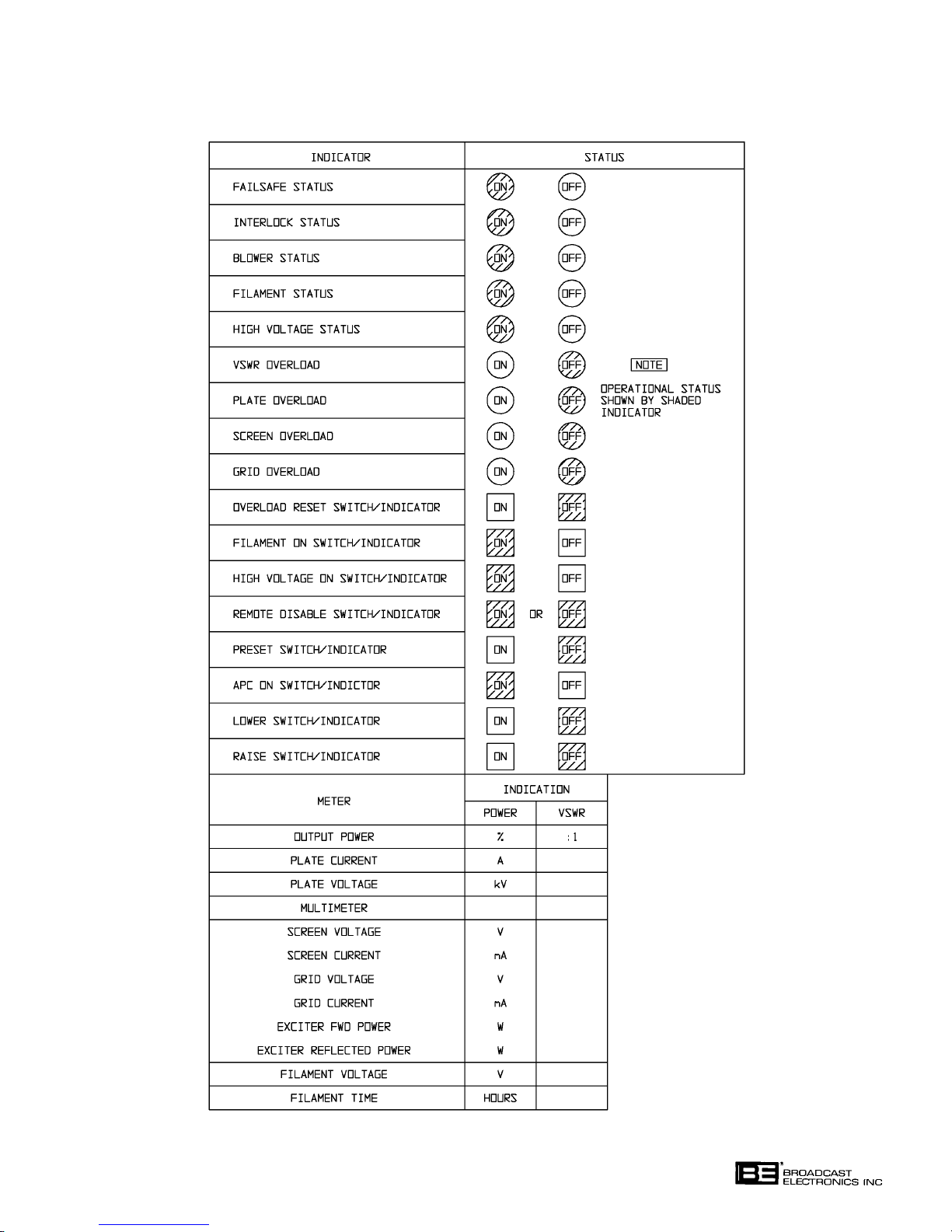
TABLE 3-2. INDICATOR CHECKLIST
597-0098-412
3-9
Page 47

SECTION IV
THEORY OF OPERATION
4-1. INTRODUCTION.
4-2. This section presents general theory of operation for the FM-5T/FM-5TS FM Transmit
ters.
4-3. The FM-5T/FM-5TS transmitters are divided into functional blocks which are discussed
by the following text. The functional blocks consist of the FM exciter, the power amplifier,
the transmitter controller, metering circuitry, and the associated power supply circuitry.
The power supply and RF circuitry are discussed in further detail at the end of this section.
The transmitter controller is described in detail by the CONTROLLER section of this
manual. Refer to Figure 4-1 and the overall schematic diagram in SECTION VII as re
quired for the following explanation.
4-4.
4-5. FM EXCITER.
4-6. The Broadcast Electronics FM-250C is a totally solid-state wideband FM exciter providing
4-7. The FM-250C will accept multiple wideband composite inputs from a stereo generator or
4-8.
4-9. The FM-5T/FM-5TS uses a single 4CX3500A tetrode to provide 5000 Watts of RF power
ELECTRICAL DESCRIPTION.
a continuously variable RF output from 25 to 250 watts. The FM-250C operates into a 50
Ohm load at any frequency within the 87.5 to 108 MHz FM broadcast band. The exciter
may be programmed to any frequency within the FM band in 10 kHz increments. The
FM-250C is mounted on slides to allow easy access to the internal semi-modular exciter
circuitry.
SCA generator as well as a 600 Ohm balanced audio input. Refer to publication 597-1004
for a detailed explanation of the FM-250C exciter features.
POWER AMPLIFIER.
on a single frequency within the FM broadcast band of 87.5 MHz to 108 MHz. The power
amplifier operates in a high-gain, grid- driven class C configuration. A patented input
circuit matches the 50 Ohm output of the IPA up to the higher grid input impedance. Use
of a large coaxial cavity results in high PA efficiency for comparatively low power consump
tion. Removal of the PA tube is a simple and quick procedure due to the cavity arrange
ment. A dual-blower cooling system forces air through the tube socket, anode fins, and out
through the main transmission line chimney. A differential air pressure sensor monitors
the effectiveness of the cooling system and removes power to the tube if air flow is inter
rupted.
4-10.
POWER AMPLIFIER CAVITY. The patented PA cavity used in the FM-5T/FM-5TS em
ploys a folded half-wave coaxial transmission line resonator constructed with aluminum
and copper tubing. This cavity design eliminates the high voltage blocking capacitors and
high current sliding contacts of conventional cavities by connecting the main transmission
line conductor directly to the anode of the power tube. A grounded concentric transmission
line center conductor tunes this cavity by varying the length inserted into the open end of a
main transmission line inner conductor. The main inner conductor is insulated from
ground and carries the anode dc potential. DC power is fed at the RF voltage null point,
approximately one-quarter wave from the anode for effective RF decoupling. A large sur
face area without sliding contacts results in minimal RF loss at this point in the cavity.
4-1
Page 48

4-11. OUTPUT COUPLING. Energy is coupled into the transmission line by an adjustable un
tuned loop which functions in the electromagnetic field within the cavity. One end of the
output loop is connected to ground, while the other connects to the center conductor of the
output transmission line through flexible straps.
4-12.
4-13. NEUTRALIZATION. Neutralization is accomplished in the FM-5T/FM-5TS by distributed
4-14.
4-15.
PLATE TUNING. Plate tuning is accomplished by adjusting a threaded rod which mechani
cally expands or contracts a beryllium copper bellows on the end of the grounded transmis
sion line center conductor inserted into the main line. Coarse frequency adjustment is ac
complished by pre-setting the length of the center conductor into the cavity.
inductance added in series between the screen connection and the screen bypass capaci
tors. The inductance develops a counteractive voltage swing between the screen and
ground which cancels out the voltage fed through the internal capacitances of the tube and
the stray capacitances of the tube socket. This form of self-neutralization results in very
stable operation and requires no adjustment when the power tube is replaced.
SECOND HARMONIC SUPPRESSOR. A patented second harmonic suppressor is in
cluded in the PA cavity. This consists of a capacitive disc and a series inductance to ground
coupled to the main transmission line at the fundamental frequency RF voltage null point.
Here the second harmonic exhibits a high voltage and the suppressor presents a low im
pedance to ground which reduces the amplitude of the second harmonic. This unique
method of harmonic suppression has minimal effect on the fundamental frequency and
does not add losses to the PA cavity at the fundamental frequency.
OUTPUT CIRCUIT. A separate low-pass filter is contained within the FM-5T/FM-5TS
cabinet to attenuate all residual second and higher order harmonics. This filter functions
over the entire FM broadcast band. Three RF directional couplers are mounted after the
filter in the output transmission line connection. Two of these supply filtered forward and
reflected power RF samples to the controller and the third port supplies a forward power
sample at 40 dB below carrier at 50 Ohms for external test equipment.
4-16.
4-17. Transmitter control operations and parameter monitoring are performed by a built-in
4-18. The controller is designed with 12 switch/indicators, 9 status indicators, 3 modem ports,
4-19. All transmitter control and monitoring operations are directed by a state-of-the-art
4-20. The controller operates from a modular switching power supply assembly. Three LEDs on
TRANSMITTER CONTROLLER.
microprocessor based controller. The controller incorporates extensive use of RFI filtering,
optical isolation, and state-of-the-art microprocessor technology to assure maximum reli
ability.
and a printer port. Adjustable timers are provided to determine filament warm-up time,
blower run-down time, overload-recycle time, and warm-up defeat time. In addition, the
controller is equipped with adjustable plate, screen, grid, and VSWR overload limits. The
timers and the overload limits are adjusted by controls on the main circuit board. The
range of all controls is limited, however so that the safe operating limits of the transmitter
cannot be exceeded by incorrect adjustment.
Z-SOFT microcontroller. The microcontroller is housed on a single plug-in daughter cir
cuit board. The circuit board plugs directly into a header on the controller main circuit
board.
the main circuit board monitor the status of the +5V, +15V, and -15V power supplies. A
Lithum battery backup system has been incorporated into the circuit design. The battery
is designed to maintain the controller memory during power failures and has a useful life
of approximately 2 years.
4-2
Page 49
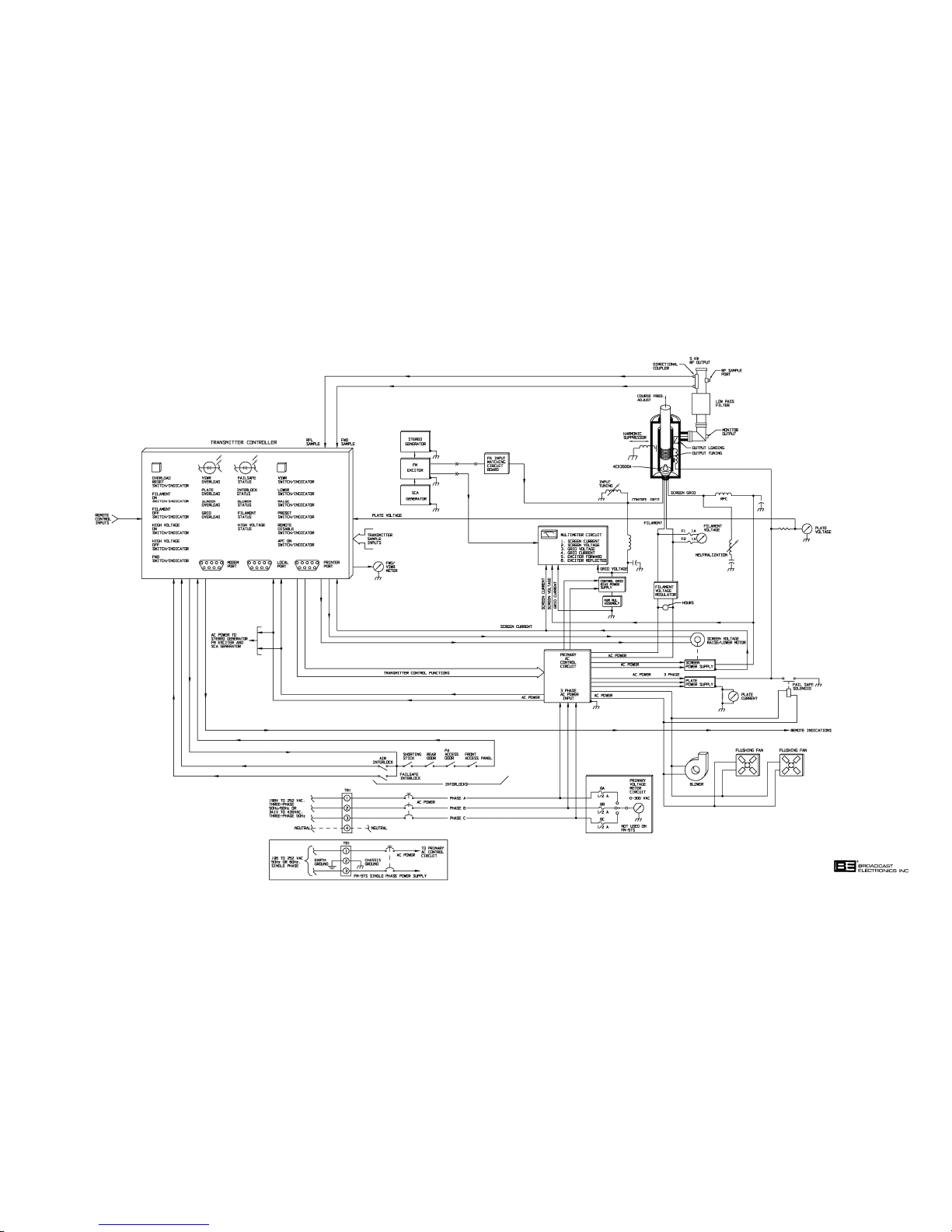
597-0033-409
FIGURE 4-1. FM-5T/FM-5TS BLOCK DIAGRAM
(4-3/4-4)
COPYRIGHT 1997 BROADCAST ELECTRONICS, INC
Page 50

4-21. The transmitter controller performs several operations. The following text presents a de
scription of the major controller functions.
4-22. AUTOMATIC RF OUTPUT LEVEL CONTROL. The controller is designed to provide manual
and automatic RF output power level controller. When the unit is configured for automatic
power control (APC) operation, the controller monitors screen current, PA forward power,
PA reflected power, and the exciter forward power and automatically adjusts the PA screen
voltage via a dc servo motor-driven variable autotransformer to maintain a constant trans
mitter RF output. If excessive PA reflected power, excessive screen current, or low exciter
power is measured, the raise power" command will be inhibited to prevent an overload
from occurring. Manual screen control is assumed by switching the APC feature to off. In
the manual mode the raise and lower switches directly control the dc servo motor to vary
the screen voltage supply. In the APC mode, the switches control a reference voltage
stored in the microprocessor memory. This memory is maintained by the battery backup
system so that the transmitter can automatically return to the desired power level when
ever power is applied.
4-23. The dc servo motor control circuit uses a full-on/full-off scheme to drive the dc servo mo
tor. This feature, combined with a deadband, eliminates hunting in this servo loop. The
front panel RAISE and LOWER switches illuminate when the motor is driven by manual
or automatic operation.
4-24.
4-25.
4-26.
4-27.
VSWR FOLDBACK PROTECTION. When the unit is in the APC mode, PA forward power
is automatically reduced if output reflected power becomes excessive enough to overload
the transmitter. As the condition which caused the high VSWR returns to normal, RF
power will be proportionately raised until full power is again restored.
SOFT START. The controller monitors PA plate voltage and reduces the screen voltage to
zero upon its absence. When the plate supply is energized, as during initial turn on, the
controller will gradually increase the screen voltage until the stored power setting is
achieved. This prevents inadvertent VSWR overloads at turn on, such as during icing of
an antenna.
MOMENTARY POWER INTERRUPTION. In the event of a momentary power interruption,
proper transmitter operation will resume immediately after power returns. If an extended
power failure occurs, information maintained by the battery back-up system will enable
the controller to initiate a start cycle to automatically return the transmitter to operation
without assistance. If the transmitter internal interlock string opens during a power fail
ure, the automatic restart feature will be defeated and the transmitter will enter the off
condition when power is re-applied.
OVERLOADS. If an overload occurs, the transmitter will deenergize, allow the overload to
clear, then automatically return to operation. If four overloads occur within 60 seconds,
the transmitter will deenergize. The overload must be manually cleared and the transmitter HIGH VOLTAGE ON switch/indicator depressed before operation will resume.
Single overloads of greater than 220 milliseconds duration will immediately deenergize the
high voltage and filament supplies.
4-28.
INDICATORS. Four LEDs are provided on the front panel as overload status indicators.
The first overload that occurs will be latched into the controller and will illuminate the ap
propriate red VSWR, PLATE, SCREEN, or GRID LED and the yellow overload reset
switch/indicator. All further overloads are monitored by the controller but will not be dis
played by the LEDs.
4-5
Page 51

4-29. Five STATUS indicators illuminate to indicate an operational condition as follows: 1) the
FAILSAFE LED indicates the external interlock is closed, 2) the INTERLOCK LED indi
cates that the internal interlock loop is closed, 3) the BLOWER LED indicates that the air
pressure is correct for the PA stage to operate, 4) the FILAMENT LED indicates primary
ac power is applied to the filament transformer, and 5) the HIGH VOLTAGE LED indi
cates primary ac power is applied to the high voltage plate supply.
4-30.
4-31. Seven front panel meters on the FM-5T and six on the FM-5TS are provided to indicate
4-32. Additional transmitter metering features include a six function multimeter. The multime
4-33.
4-34. POWER SUPPLIES.
4-35. The FM-5T transmitter is designed for operation from a 196 to 252 volt three phase ac in
METERING.
transmitter operating parameters. Output power and output VSWR indications are pre
sented on a precision output power meter. Plate voltage and plate current information are
displayed on separate meters for optimum convenience.
ter selects and displays information on vital transmitter operating parameters such as:
1) screen current, 2) screen voltage, 3) grid current, 4) grid voltage, 5) exciter forward pow
er, and 6) exciter reflected power. An iron-vane voltmeter is used to measure filament
voltage. A FILAMENT TIME meter is provided to indicate hours of filament circuit op
eration. On FM-5T models, primary ac voltage monitoring is provided by a primary ac
voltmeter. The meter selects and displays the voltage between all three phases of the ac
input. All meter currents are measured on the ground side of each supply to prevent high
voltages across the meters.
EXCITER METERING. The exciter operating parameters are displayed by two additional
meters and three status indicators. For detailed information on exciter metering, refer to
FX-250C exciter manual 597-1004.
put. The plate supply is a conventional three phase power supply circuit. The remaining
FM-5T transmitter power supplies are single phase circuits which are obtained from two
phases of the three phase input. The FM-5TS transmitter is designed for operation from a
196 to 252 volt single phase ac input. All FM-5TS transmitter power supplies are single
phase circuits obtained from the transmitter ac input.
4-36. The grid bias and screen power supplies consist of conventional full-wave rectification and
choke input filter sections. A hum-null assembly consisting of a small unfiltered full-wave
rectified supply injects a 120 Hz pulsating dc voltage in series with the ground return of
the grid bias supply to cancel residual ripple from the screen supply in the tetrode amplifi
er.
4-37. The FM-5T plate supply is a three-phase primary, six-phase secondary supply. The pri
mary circuit is connected in a closed delta arrangement and the secondary is connected in
a wye configuration. The supply consists of a 3-phase full-wave bridge rectifier network
with an LC filter section. Advantages of this type of supply is good regulation and low rip
ple which requires little filtering. The FM-5TS plate supply consists of a single phase fullwave rectifier network with a resonant LC filter stage. Power is applied to each plate sup
ply through a step-start circuit to reduce the inrush current at power-on. This limits
stress and extends component life.
4-38. The filament supply consists of a variable transformer assembly which is used to adjust a
high-current low-voltage regulator assembly. The regulator assembly is designed to regu
late a wide range of ac input potentials into a stable 240 ±1% volt output.
4-39. Each modular component of the transmitter is equipped with a self-contained ac power
supply. In addition, a battery back-up supply in the transmitter controller maintains op
erational information during power outages.
4-6
Page 52

4-40. DETAILED DESCRIPTION.
4-41. FM-5T POWER SUPPLY.
4-42. A 196 volt to 252 volt, 50 Hz or 60 Hz, three-phase ac input is required for proper opera
tion of the FM-5T transmitter. The following supplies operate from the ac input (typical
values are shown for the rated RF power output):
PARAMETER APPROXIMATE VALUES
A. PA PLATE +5300V at 1.3 Amperes
B. PA SCREEN GRID +525V at 0.060 Amperes
C. PA CONTROL GRID -260V at 0.045 Amperes
D. PA FILAMENT 5V ac at 90 Amperes
E. HUM NULL +12.6V at 0.040 Amperes
4-43.
4-44. When the FILAMENT ON switch/indicator is depressed, optically-coupled-relay K1 will
4-45. Assuming the HIGH VOLTAGE ON switch/indicator has been depressed, and the PA fila
4-46. If during a start sequence an internal interlock opens, the entire start sequence will be
SEQUENCE OF OPERATION. When the transmitter fused disconnect is closed, power is
applied through AC POWER circuit breaker CB1 to: 1) the contacts of high voltage step
contactor K7, 2) the contacts of high voltage start contactor K4, and 3) the contacts of fila
ment/driver contactor K3 (see Figure 4-2). Power is also applied through BLOWER circuit breaker CB2 to the transmitter controller and to blower control relay K1.
apply power to blower B1, flushing fans B2 and B3, and energize high voltage shorting so
lenoid K5. After the blower comes up to speed, the air interlock will close and opticallycoupled-relay K2 will energize filament/driver contactor K3 which applies power to: 1) the
PA filament supply, 2) the PA control grid supply, 3) the hum-null power supply, 4) the FM
exciter, and 5) the optional stereo and SCA generators.
ment heating delay of at least ten seconds has expired, optically-coupled-relay K6 will
pulse step contactor K7. After the current inrush to the plate supply has been limited by
the step/start resistors (R1, R2, and R3), optically-coupled-relay K5 will energize start
contactor K4 to apply full input to the plate and screen power supplies.
cancelled and must be re-initiated manually. If an internal interlock opens during opera
tion, the entire power supply section will deenergize. However, if the interlock is promptly
closed, the blower and flushing fans will resume operation to cool the PA tube but a new
start sequence will have to be initiated manually. Whenever power is removed from the
blower and flushing fans, the high voltage discharge solenoid will short the plate supply to
ground.
4-47. If the HIGH VOLTAGE OFF switch/indicator is depressed, the plate and screen power
supplies will deenergize. If the FILAMENT OFF switch/indicator is depressed, all re
maining power supplies will deenergize. The blower and flushing fans will continue opera
tion for 30 seconds or more to cool the PA tube, then deenergize.
4-48.
4-49. The secondary of the high voltage transformer is connected in a wye configuration. Due to
PA PLATE POWER SUPPLY. The plate power supply is a three-phase primary, six-phase
secondary supply. The primary circuit is connected in a closed delta arrangement and pro
tected by circuit breaker CB1. Component stress at power on is eliminated by a step/start
circuit which limits supply inrush current.
the physical construction of the transformer, each phase appearing in the secondary will
lead and lag a respective phase appearing in the primary by 60 degrees. The secondary
phase separation of 60 degrees divided into one primary phase of 360 degrees equals six
secondary phases.
4-7
Page 53

4-50. Minimal filtering is required as only 4.2 percent ripple is output from the rectifiers. One
requirement of the multiphase supply, however is that the primary ac input must be bal
anced to within the percentage of ripple voltage which is to be obtained from the supply.
Constant primary ac line unbalance can be corrected by the use of primary taps or a
tapped three-phase autotransformer.
4-51. Filtering for the supply is accomplished by a one-section choke-input filter. The choke is
inserted in the negative leg of the rectified output to eliminate the dc potential between the
choke and ground. The negative leg of the supply is referenced to ground through the PA
stage current meter shunt. A single shunt capacitor bypasses residual ac ripple at fre
quencies of 300 to 360 Hz and higher to ground. A bleeder resistor connected across the
supply increases regulation and, in conjunction with high voltage discharge solenoid K5,
enhances safety. A series resistance in the anode dc feedline limits peak energy in case of
arc-overs in the power amplifier stage or high voltage discharge solenoid operations.
4-52. Component stress at power-on is eliminated by a step/start circuit which limits plate sup
ply inrush current. The step/start circuit is interlocked through contacts of the filament
circuit breaker and the filament/driver contactor to assure that the filament circuit is ener
gized before a high-voltage-on sequence can be initiated. The controller will energize the
step contactor via K6. After 100 milliseconds, the controller will energize the start contac
tor via K5. The step contactor will deenergize after it has been energized for 160 millisec
onds. In this manner, the current limiting resistors will only be subject to heating during a
100 millisecond interval between the step/start relay closures.
PA SCREEN GRID POWER SUPPLY. The screen power supply is a full-wave bridge-recti
4-53.
fied supply with a single L-section filter. The primary of the screen transformer is con
nected through CB3 to the step/start contactors. The output of the screen supply is adjust
able with a variable autotransformer connected in the primary of the screen transformer.
A dc motor connected to the variable autotransformer allows both manual and automatic
control of the screen voltage. The choke in this supply is connected in the negative leg of
the supply to eliminate the dc potential between the choke and ground. A bleeder resistor
connected across this supply improves regulation and enhances safety by discharging C6.
4-54.
4-55. Hum Null Supply. The ground path for the grid bias supply is routed through the hum-
4-56.
PA CONTROL GRID POWER SUPPLY. The control grid bias supply is a full-wave bridge-
rectified supply with a single L-section filter. The primary of the supply is connected to
the primary ac input through CB5 and filament/driver contactor K3. A bleeder resistor
connected across this supply improves regulation and enhances safety by discharging C9, a
relatively high capacity electrolytic capacitor.
null circuit which introduces a small 120 Hz pulsating dc component into the control grid
bias supply to cancel hum in the PA tube from the screen supply. The amount of voltage
added to the negative side of the control grid bias supply is adjusted by R10. This voltage
is out-of-phase with the 120 Hz ripple component of the screen supply.
PA FILAMENT SUPPLY. The PA filament supply is a low-voltage high current ac supply.
Overload protection for the circuit is provided by circuit breaker CB5. Filament voltage
regulator VR200 provides a stable ac input voltage environment. Variable transformer T5
provides accurate filament voltage adjustment. A FILAMENT TIME meter indicates
hours of filament circuit operation.
4-8
Page 54
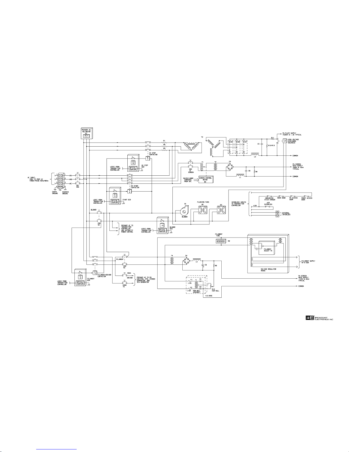
597-0033-411
FIGURE 4-2. FM-5T POWER SUPPLY SIMPLIFIED
SCHEMATIC
(4-9/4-10)
COPYRIGHT 1997 BROADCAST ELECTRONICS, INC
Page 55

4-57. FM-5TS POWER SUPPLY.
4-58. A 196 volt to 252 volt, 50 Hz or 60 Hz, single-phase ac input is required for operation of
the FM-5TS transmitter. The following supplies operate from the ac input (typical values
are shown for the rated RF power output):
PARAMETER APPROXIMATE VALUES
A. PA PLATE +5300V at 1.3 Amperes
B. PA SCREEN GRID +525V at 0.060 Amperes
C. PA CONTROL GRID -260V at 0.045 Amperes
D. PA FILAMENT 5V ac at 90 Amperes
E. HUM NULL +12.6V at 0.040 Amperes
4-59. SEQUENCE OF OPERATION. Power is applied through AC POWER circuit breaker CB1
to: 1) the contacts of high voltage step contactor K7, 2) the contacts of high voltage start
contactor K4, and 3) the contacts of filament/driver contactor K3 (see Figure 4-3). Power
is also applied through BLOWER circuit breaker CB2 to: 1) the transmitter controller, 2)
blower control relay K1, and 3) filament control relay K2.
4-60. When the FILAMENT ON switch/indicator is depressed, optically-coupled-relay K1 will
apply power to blower B1, flushing fans B2 and B3, and energize high voltage shorting so
lenoid K5. After the blower comes up to speed, the air interlock will close and opticallycoupled-relay K2 will energize filament/driver contactor K3 which applies power to: 1) the
PA filament supply, 2) the PA control grid supply, 3) the hum-null power supply, 4) the FM
exciter, and 5) the optional stereo and SCA generators.
4-61. Assuming the HIGH VOLTAGE ON switch/indicator has been depressed, and the PA fila
ment heating delay of at least ten seconds has expired, optically-coupled-relay K6 will
pulse step contactor K7. After the current inrush to the plate supply has been limited by
the step/start resistors (R1 and R2), optically-coupled-relay K5 will energize start contac
tor K4 to apply full input to the plate and screen power supplies.
4-62. If during a start sequence an internal interlock opens, the entire start sequence will be
cancelled and must be re-initiated manually. If an interlock opens during operation, the
entire power supply section will deenergize. However, if the interlock is promptly closed,
the blower and flushing fans will resume operation to cool the PA tube but a new start se
quence will have to be initiated manually. Whenever power is removed from the blower
and flushing fans, the high voltage discharge solenoid will short the plate supply to
ground.
4-63. If the HIGH VOLTAGE OFF switch/indicator is depressed, the plate and screen power
supplies will deenergize. If the FILAMENT OFF switch/indicator is depressed, all re
maining power supplies will deenergize. The blower and flushing fans will continue opera
tion for 30 seconds or more to cool the PA tube, then deenergize.
4-64.
PA PLATE POWER SUPPLY. The plate power supply is a full-wave bridge-rectified supply
with a two-section filter. The first filter section includes a 120 Hz resonant choke. This
section provides good load regulation, low 120 Hz ripple, and lower stored energy than con
ventional filter sections with similarly sized components. The filter location in the nega
tive leg of the rectifier output eliminates the dc potential between the choke and ground. A
pi-section filter follows the resonant choke which reduces high frequency components
which are passed by the resonant choke. The choke in the pi-section is also connected in
the negative leg of the supply to eliminate the dc potential between the choke and ground.
A bleeder resistor connected across the supply improves regulation, and in conjunction
with high voltage discharge solenoid K5, enhances safety. A series resistance in the anode
dc feed limits peak energy in case of arc-overs in the power amplifier stage and during
high voltage discharge solenoid operation.
4-11
Page 56

4-65. Component stress at power-on is eliminated by a step/start circuit which limits plate sup
ply inrush current. The step/start circuit is interlocked through contacts of the filament
circuit breaker and the filament/driver contactor to assure that the filament circuit is energized before a high-voltage-on sequence can be initiated. The controller will energize
the step contactor via K6. After 100 milliseconds, the controller will energize the start con
tactor via K5. The step contactor will deenergize after it has been energized for 160 milli
seconds. In this manner, the current limiting resistors will only be subject to heating dur
ing a 100 millisecond interval between the step/start relay closures. The limiting resistors
are disconnected from the lines after 160 milliseconds, improving reliability.
PA SCREEN GRID POWER SUPPLY. The screen power supply is a full-wave
4-66.
bridge-rectified supply with a single L-section filter. The primary of the screen transform
er is connected through CB3 to the step/start contactors. The output of the screen supply
is adjustable with a variable autotransformer connected in the primary of the screen trans
former. A dc motor connected to the variable autotransformer allows both manual and au
tomatic control of the screen voltage. The choke in this supply is connected in the negative
leg of the supply to eliminate the dc potential between the choke and ground. A bleeder
resistor connected across this supply improves regulation and enhances safety by discharg
ing C6.
4-67.
4-68. Hum Null Supply. The ground path for the grid bias supply is routed through the hum-
4-69.
4-70.
4-71. FM EXCITER. The modulated FM signal for RF circuit operation is generated by the
4-72.
PA CONTROL GRID POWER SUPPLY. The control grid bias supply is a full-wave bridge-
rectified supply with a single L-section filter. The primary of the supply is connected to
the primary ac input through CB5 and filament/driver contactor K3. A bleeder resistor
connected across this supply improves regulation and enhances safety by discharging C9.
null circuit which introduces a small 120 Hz pulsating dc component into the control grid
bias supply to cancel hum in the PA tube from the screen supply. The amount of voltage
added to the negative side of the control grid bias supply is adjusted by R10. This voltage
is out-of-phase with the 120 Hz ripple component of the screen supply.
PA FILAMENT SUPPLY. The PA filament supply is a low-voltage high current ac supply.
Overload protection for the circuit is provided by circuit breaker CB5. Filament voltage
regulator VR200 provides a stable ac input voltage environment. Variable transformer T5
provides accurate filament voltage adjustment. A FILAMENT TIME meter indicates
hours of filament circuit operation.
RF CIRCUITRY.
FM-250C FM exciter (see Figure 4-4). Approximately 140 watts of drive is required to
operate the PA circuitry. Refer to publication 597-1004 for a complete description of the
FM exciter.
POWER AMPLIFIER. The PA stage contains a single 4CX3500A tetrode operated class C in
a folded half-wave cavity to output 5 kW of RF power with approximately 150 Watts of RF
drive. The following text describes the operation of components and circuits within the PA
stage.
4-73. PA Input Circuit. The grid impedance-matching circuit used in the FM-5T/FM-5TS trans
mitter consists of a combination of series inductor and shunt capacitor circuit board ele
ments, implemented with a printed circuit board. The inductors and capacitors are etched
into the copper-clad laminate. Multiple LC sections match the 50 Ohm source impedance
to the 300 to 400 Ohm input impedance of the grid-driven RF power amplifier.
4-12
Page 57
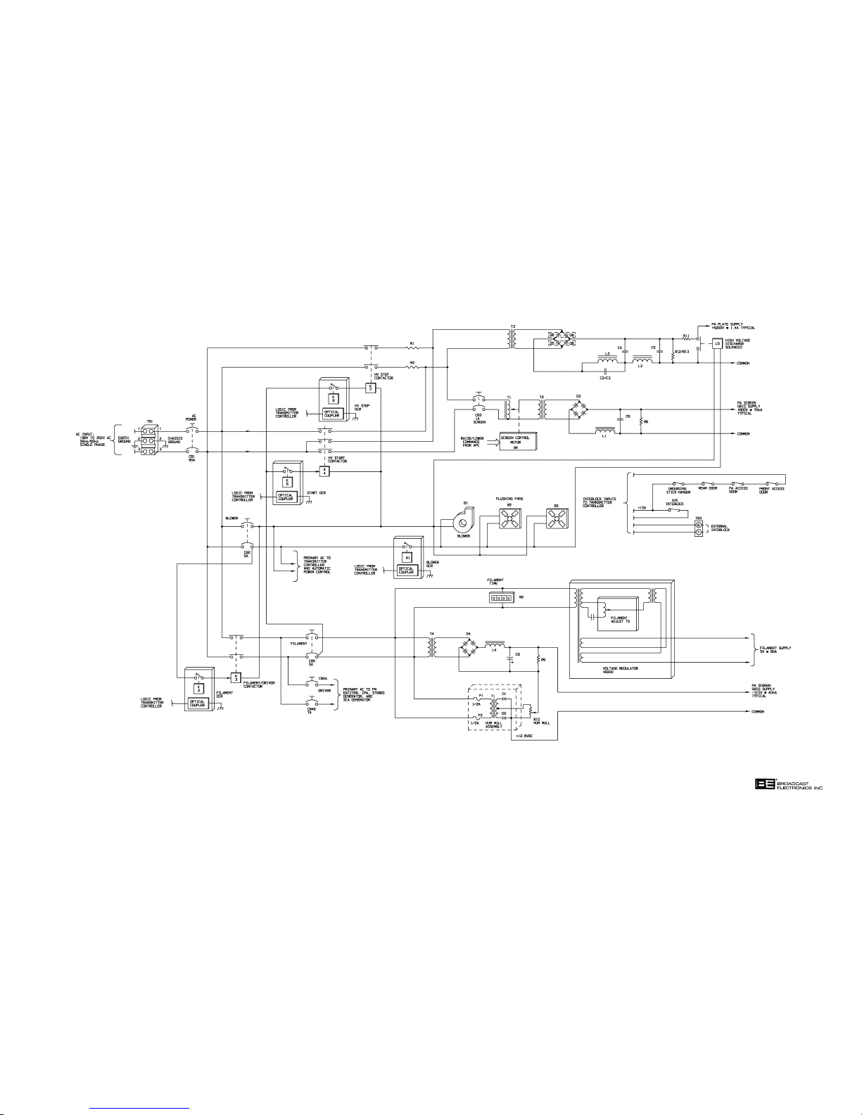
597-0033-412
FIGURE 4-3. FM-5TS POWER SUPPLY
SIMPLIFIED SCHEMATIC
(4-13/4-14)
COPYRIGHT 1997 BROADCAST ELECTRONICS, INC
Page 58

4-74. This input matching design provides a wide bandwidth and improves reliability, stability,
and maintainability of the transmitter. A single tuning control in the input circuit is suffi
cient to tune and match the 50 Ohm IPA impedance to the high input impedance of the
grid over the 88 to 108 MHz FM broadcast band with a 4:1 range of RF power levels. The
input-matching circuit also eliminates separately mounted components which can be mi
crophonically sensitive to vibrations due to mechanical instability in the cooling air flow.
4-75. The grid circuit is adjusted for proper operation with two paralleled slider" inductors
which connect to ground. These controls employ sliding shorts to tune the grid capacitance
to resonance. One inductor is mechanically connected to the front panel input tuning control while the other inductor is connected to a counter in the rear of the FM-5T/FM-5TS.
Fine tuning is accomplished by adjusting either one of the inductors (normally the front
panel control). A resistive loading component is included in the input circuit to broaden its
overall response. The filament bypassing and grid blocking capacitors are specially fabri
cated in a sandwich-type construction with etched copper-clad Kapton dielectrics for high
capacitance with negligible inductance.
4-76. The screen grid ring is connected through eight flexible adjustable straps to four copper-
clad Kapton bypass capacitors to ground. Self-neutralization is accomplished by adjusting
the length of the straps, thereby varying the series inductance. This introduces an
out-of-phase current component causing a voltage swing across the screen to ground
which cancels out the voltage fed through internal plate-to-grid capacitances of the tube.
A spark gap is included to safely bypass energy if the tube should arc internally.
4-77. Power Amplifier Cavity. The PA cavity used in the FM-5T/FM-5TS employs a folded half-
wave coaxial transmission line resonator constructed with aluminum and copper tubing.
This cavity design eliminates the high voltage blocking capacitors and high current short
ing contacts of conventional cavities by connecting the main transmission line conductor
directly to the anode of the power tube (see Figure 4-5). A grounded concentric transmis
sion line center conductor tunes this cavity with a variable reentrant length inserted into
the end of a main inner conductor. The main inner conductor is insulated from ground and
carries the anode dc potential. DC power is fed at the RF voltage null point which is
approximately one-quarter wave from the anode for effective RF decoupling. A large sur
face area without sliding contacts results in minimal loss at this point. Incorporated into
the tank design is a second-harmonic suppressor. Rather than attenuating the second
harmonic after the signal has been generated and amplified, the circuitry in the FM-5T
essentially eliminates formation of this signal by series LC trapping the second harmonic
waveform at the point where the wave exhibits a high voltage, approximately one-quarter
wave length from the anode.
4-78. Plate tuning is accomplished by an adjustable bellows on the grounded or center portion of
the plate line which is maintained at chassis ground potential. The PA plate potential is
applied to the main conductor (the fixed portion of the plate line) at the fundamental frequency RF voltage null point. This point is also the point at which the second harmonic
will peak in voltage. The basic LC circuit placed at this point will essentially eliminate the
second harmonic component in the plate current waveform.
4-79. PA Output Circuit. Output coupling is accomplished with an untuned loop intercepting the
magnetic field concentration at the voltage null point of the main line. The PA loading con
trol varies the angular position of the plane of the loop with respect to the plate line,
changing the amount of magnetic field which it intercepts. Multiple phosphor bronze
leaves connect one side of the output loop to ground and the other side to the center con
ductor of the output transmission line connection. This allows for mechanical movement
of the loop by the PA loading control without utilizing any sliding contacts. The grounded
loop improves immunity to lightning and static buildup on the antenna connection.
4-15
Page 59

4-80. A pair of directional couplers located in the output transmission line provide RF output
voltages proportional to the PA forward and reflected power. The RF output voltages are
rectified and amplified to provide power and VSWR indications on the OUTPUT POWER
meter and samples for the transmitter controller. An additional port in the transmission
line provides a point to connect a station modulation monitor.
4-81.
4-82.
4-83. PA forward and reflected power samples from the transmitter low-pass filter are applied to
PA METERING. Seven meters on the FM-5T and six on the FM-5TS are used to indicate
transmitter operating parameters. The plate current, multimeter, and the filament voltage
meters measure samples from a PA metering circuit board which is mounted on the side of
the RF enclosure. Additional samples from this circuit board are routed to the controller
for overload and diagnostic features. The PA metering circuit board also contains fuses
which protect the filament meter wiring. Plate voltage metering is obtained from a high
voltage meter multiplier circuit board. Power output metering is derived from circuitry
within the controller. A filament time meter indicates total elapsed time of filament circuit
operation. The filament voltage meter is an iron vane type and accurately measures the
filament voltage at the cavity feed-thru terminals. On FM-5T models, monitoring of ac
input potentials is provided by a primary ac voltage meter.
AUTOMATIC POWER CONTROL. The transmitter controller monitors a number of trans
mitter parameters to function as part of a closed loop which maintains a constant RF out
put level from the transmitter (see Figure 4-4).
individual rectifier/amplifier circuits in the controller. The outputs from the rectifier/am
plifier circuits are routed to analog-to-digital (A-to-D) circuitry. The A-to-D circuitry
converts the signals to a digital format and routes the signals to the microprocessor. The
microprocessor uses the signals: 1) to output forward power and VSWR samples to the out
put power meter, 2) to output forward and reflected power samples to the remote meter
terminals, and 3) for automatic RF output power control operations. The controller moni
tors several parameters such as the forward and reflected power, screen current, and excit
er forward power to determine if power control and correction is required. When automatic
power control is enabled and power correction is required, the controller will use the ad
justable screen supply autotransformer to obtain the desired power level.
4-84. When APC operation is enabled and as RF output power varies, the controller will act to
maintain the established RF output level. If inadequate exciter drive exists for normal op
eration, PA reflected power increases, or if screen current is high, any power increase will
be inhibited. If the PA reflected power increases to a point which may damage the RF cir
cuitry of the transmitter, the controller will reduce the RF output to a safe level and the
transmitter will continue to operate. Full power will be automatically re-established when
the VSWR condition is corrected.
4-85. As an additional function, the controller will reduce the PA screen potential to minimum
whenever the plate voltage is off. Whenever the plate voltage is energized, the controller
will gradually increase the PA screen voltage until the rated transmitter RF output is es
tablished unless limited by low exciter drive, a high VSWR condition, or high screen cur
rent.
4-16
Page 60
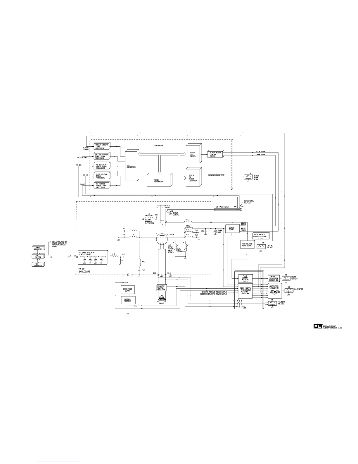
597-0033-410
FIGURE 4-4.
RF CIRCUIT SIMPLIFIED SCHEMATIC
(4-17/4-18)
COPYRIGHT 1997 BROADCAST ELECTRONICS, INC
Page 61
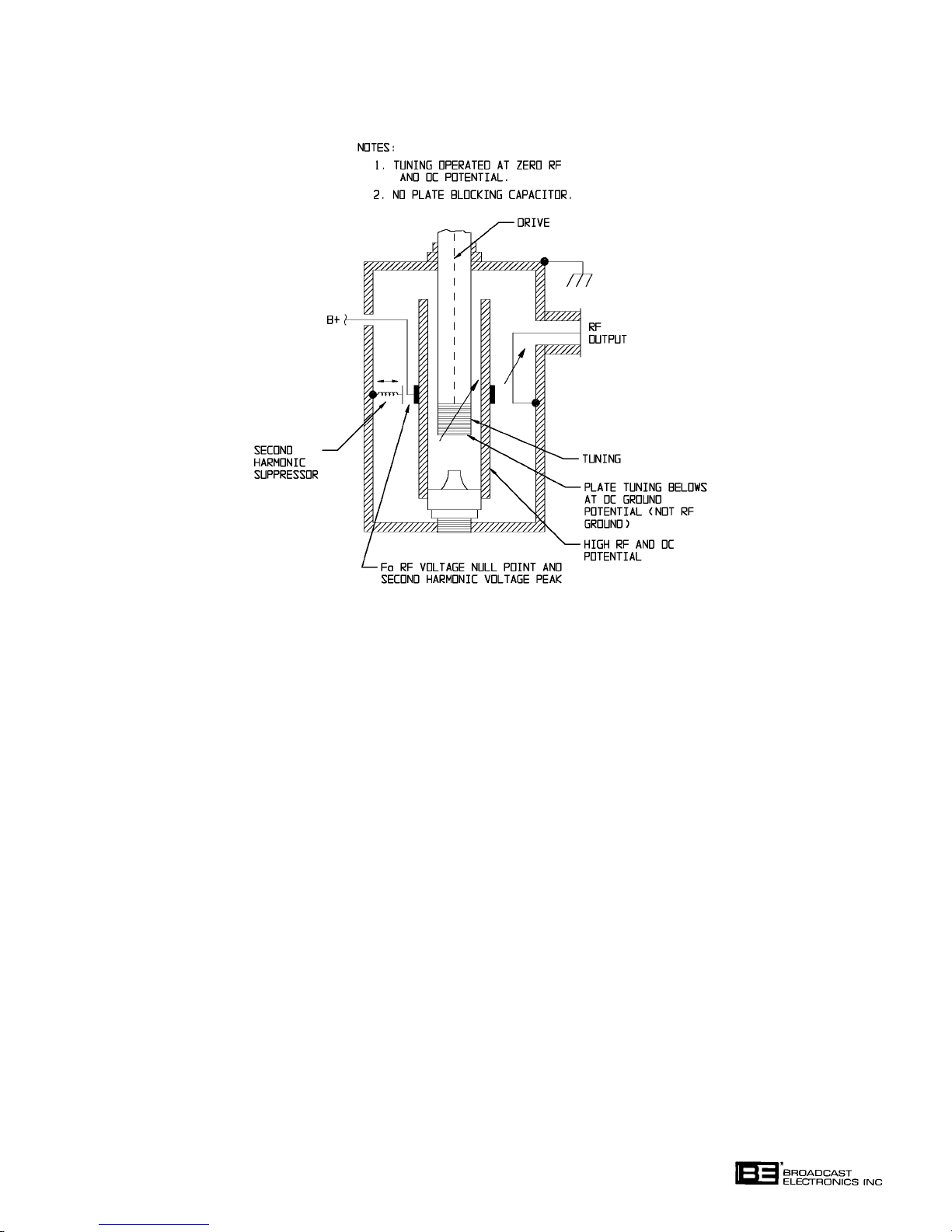
FIGURE 4-5. PA CAVITY
COPYRIGHT 1997 BROADCAST ELECTRONICS, INC
597-0032-32
4-19
Page 62

SECTION V
MAINTENANCE
5-1. INTRODUCTION.
5-2. This section provides general maintenance information, electrical adjustment procedures,
and troubleshooting information for the FM-5T/FM-5TS transmitters.
5-3. SAFETY CONSIDERATIONS.
WARNING
NEVER OPEN THE EQUIPMENT UNLESS ALL TRANS
MITTER PRIMARY POWER IS DISCONNECTED. USE
WARNING
THE GROUNDING STICK PROVIDED TO ENSURE ALL
COMPONENTS AND ALL SURROUNDING COMPO
NENTS ARE DISCHARGED BEFORE ATTEMPTING
MAINTENANCE ON ANY AREA WITHIN THE TRANS
MITTER.
5-4. The FM-5T/FM-5TS transmitters contain high voltages and currents which, if regarded
carelessly, could be fatal. The transmitter has many built-in safety features, however good
judgement, care, and common sense are the best accident preventives. The maintenance
information contained in this section should be performed only by trained and experienced
maintenance personnel.
5-5. It is very dangerous to attempt to make measurements or replace components with power
energized, therefore such actions are not recommended. The design of the equipment pro
vides safety features such that when a door is opened or an access panel is removed, inter
lock switches will deenergize all dc power supplies and release the fail-safe discharge sole
noid across the plate supply. Do not short out or bypass interlock switches as a mainte
nance short cut.
5-6. The PA cavity access door actuates an interlock switch if the door is opened during trans
mitter operation. All dc supplies will be deenergized and the plate supply will be shorted
to ground. AC power to the entire cabinet may be disconnected with the front panel AC
POWER ON/OFF circuit breaker.
5-7. A grounding stick is provided as a safety feature. The grounding stick consists of a metal
hook with an insulated handle. The metal end is connected to chassis ground. Use the
grounding stick to touch every part in the area or circuit on which maintenance is to be
performed before attempting maintenance.
5-8. The grounding stick rests on a hook switch. When the grounding stick is removed, the as
sociated hook switch will open the transmitter interlock string and deenergize all transmit
ter dc potentials until the grounding stick is replaced on its respective hook switch.
WARNING: DISCONNECT POWER PRIOR TO SERVICING
5-1
Page 63

5-9. FIRST LEVEL MAINTENANCE.
WARNING
NEVER OPEN THE EQUIPMENT UNLESS ALL TRANS
MITTER PRIMARY POWER IS DISCONNECTED.
WARNING
5-10. First level maintenance consists of those precautionary measures applied to the equipment
to forestall future failures. These procedures are performed on a regular basis and the re
sults recorded in a maintenance log. Preventive maintenance of the transmitter consists of
good housekeeping, lubrication, and checking the performance levels using the meters and
various indicators built into the equipment.
WARNING
NEVER OPEN THE EQUIPMENT UNLESS ALL TRANS
MITTER PRIMARY POWER IS DISCONNECTED. USE
WARNING
THE GROUNDING STICK PROVIDED TO ENSURE ALL
COMPONENTS AND ALL SURROUNDING COMPO
NENTS ARE DISCHARGED BEFORE ATTEMPTING
MAINTENANCE ON ANY AREA WITHIN THE TRANS
MITTER.
5-11. On a regular basis, clean the equipment of accumulated dust. Check for overheated com
ponents, tighten loose hardware, and lubricate mechanical surfaces as required. A lubri
cant such as Lubriplate" should be applied sparingly to the tuning drives, cables, the PA
tuning line right angle gear mechanism, and the cyclometer drives behind the front panel.
The PA output loading screw drive should be opened (four screws) and lubricated every 36
months, or more often if resistance is noted.
5-12.
5-13. The transmitter controller is equipped with a Lithium battery. The battery has a useful
5-14.
5-15. Air filter replacement is accomplished outside the transmitter without interrupting equip
5-16. The transmitter uses one disposable type air filter 1 inch X 16 inches X 20 inches (2.54 cm
CONTROLLER BATTERY.
life of approximately two years. After approximately two years of service, replace the con
troller battery using BEI part number 350-2032.
AIR FILTER.
ment operation. The filter should be checked once each week with replacement done on an
as-needed basis. A dirty filter could result in dirt accumulation leaking into the cabinet
from seams, door jambs, etc. Never reverse a dirty filter. Always replace the filter.
X 40.64 cm X 50.8 cm) mounted in the rear door of the cabinet. Additional filters may be
ordered for replacement (P/N 407-0062) or locally purchased. Always mount the filter
with the airflow arrow pointing towards the blower. The exciter is also equipped with an
air filter. Refer to the exciter manual for additional information.
WARNING: DISCONNECT POWER PRIOR TO SERVICING
5-2
Page 64

5-17. BLOWER MAINTENANCE.
WARNING
NEVER OPEN THE EQUIPMENT UNLESS ALL TRANS
MITTER PRIMARY POWER IS DISCONNECTED. USE
WARNING
THE GROUNDING STICK PROVIDED TO ENSURE ALL
COMPONENTS AND ALL SURROUNDING COMPO
NENTS ARE DISCHARGED BEFORE ATTEMPTING
MAINTENANCE ON ANY AREA WITHIN THE TRANS
MITTER.
5-18. Inspect the blower and the cabinet flushing fans for dust accumulation and periodically
clean the blower and fans using a paint brush and vacuum cleaner. Both the fan and
blower bearings are sealed and do not permit lubrication. If a bearing fails, the motor
must be replaced. The blower and fan mounting bolts should be checked for tightness.
5-19. The blower and fan motors are cooled by the air passing around each motor. If the ambient
air temperature is too high or if the air flow is restricted, then the lubricant will gradually
vaporize from the motor bearings and bearing failure will occur. If very dirty air passes
over the motors, accumulated dust will impair the motor cooling unless the accumulation is
wiped from and blown out of the motor.
5-20. The blower and fan impeller blades should be inspected and cleaned periodically. If the
transmitter is operated in a very dusty environment, dust will build up on the concave side
of the blower and fan impellers. If this happens, air flow will be reduced and unbalance
will result with a possibility of damage to the blower or fans.
5-21.
SECOND LEVEL MAINTENANCE.
WARNING
NEVER OPEN THE EQUIPMENT UNLESS ALL TRANS
MITTER PRIMARY POWER IS DISCONNECTED.
WARNING
5-22. Second level maintenance consists of procedures required to restore the transmitter to sat
isfactory operation after a fault has occurred. The maintenance philosophy for the
FM-5T/FM-5TS transmitters consists of problem isolation to a specific area. Subsequent
troubleshooting provided by each applicable assembly publication in Part II of this manual
will assist problem isolation to a replaceable assembly or component. If desired, a replace
able assembly may be returned to the factory for repair or exchange.
GENERAL.
5-23.
5-24. PA STAGE. Power amplifier tube life is a result of several circuit parameters. Usually,
the first indication of the decline of a tube is a slight reduction in power output. This can
normally be corrected by a small increase in filament voltage. It may be wise to order a
new tube at this time. Further reductions in power output can be compensated in the
same manner only a limited number of times. Refer to the Eimac application paper titled
Extending Transmitter Tube Life" included in the Manufacturers Data" section of this
manual. Excess control grid or screen grid dissipation will shorten the life of a tube. Also,
excess plate dissipation signals nothing but trouble. PA efficiency versus RF power is plot
ted on Figure 5-1 and should be referenced to estimate PA efficiency for a particular power
level.
WARNING: DISCONNECT POWER PRIOR TO SERVICING
5-3
Page 65
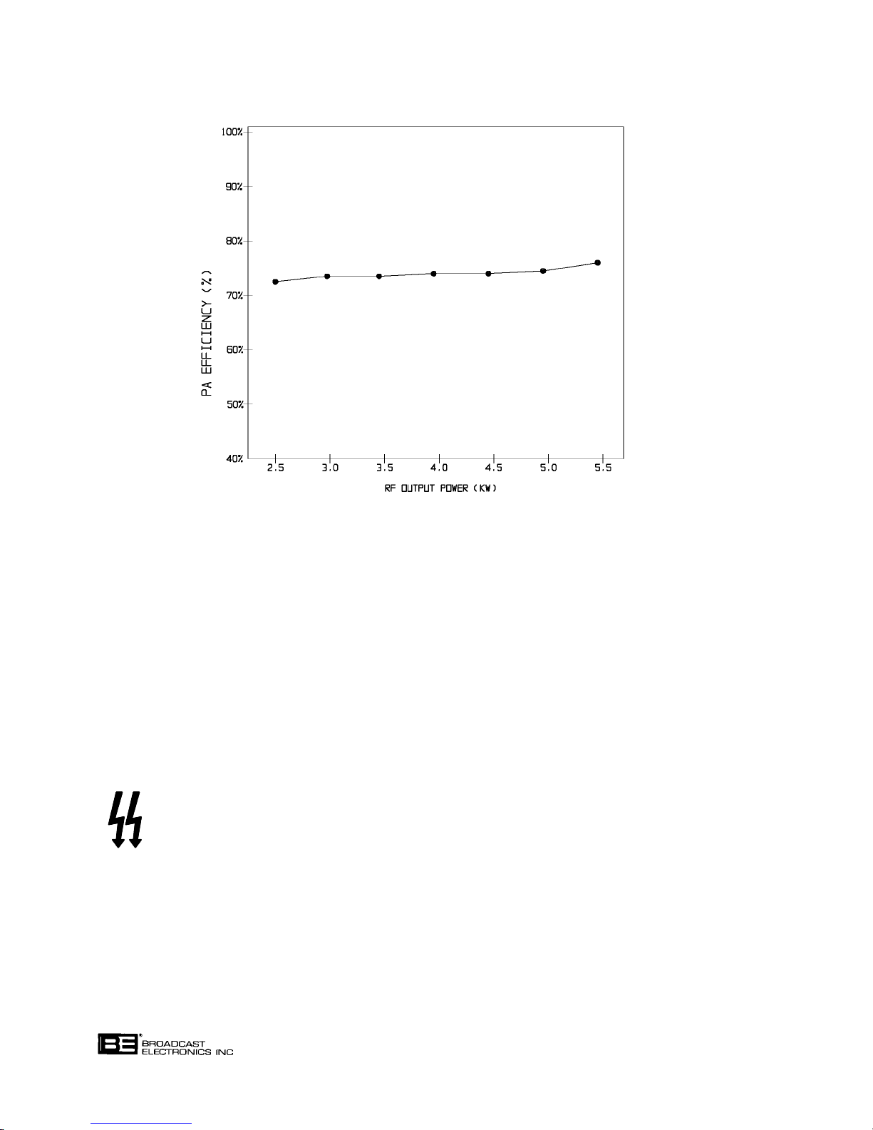
COPYRIGHT 1997 BROADCAST ELECTRONICS, INC
597-0033-11
FIGURE 5-1. TYPICAL PA EFFICIENCY CURVE AT 98.1 MHz
(Within ±2% from 87.5 to 108 MHz)
5-25. PA Tube Warranty. The FM-5T/FM-5TS PA tube is covered by warranty from the Varian/
Eimac Company, the tube manufacturer, not Broadcast Electronics, Inc. However, a tube
purchased from Broadcast Electronics which is defective must be returned to Broadcast
Electronics with a customer-completed warranty claim service report. A warranty claim
service report form is shipped with each tube obtained from Broadcast Electronics, Inc.
Following this procedure will expedite immediate shipment of a new tube. Contact the
Broadcast Electronics, Inc. Customer Service Department for additional details as re
quired. It is recommended that the warranty report be filled out as soon as the new tube is
placed in operation while the nominal voltages are known.
5-26.
ADJUSTMENTS.
WARNING
WARNING
5-27. Adjustment procedures for controls associated with the transmitter controller are pre
sented in the CONTROLLER section of this manual. Adjustment procedures for the power
supply and PA controls are presented as follows:
A. AM Noise.
B. Plate Current Meter Calibration.
WARNING: DISCONNECT POWER PRIOR TO SERVICING
NEVER OPEN THE EQUIPMENT UNLESS ALL TRANS
MITTER PRIMARY POWER IS DISCONNECTED. USE
THE GROUNDING STICK PROVIDED TO ENSURE ALL
COMPONENTS AND ALL SURROUNDING COMPO
NENTS ARE DISCHARGED BEFORE ATTEMPTING ANY
MAINTENANCE.
5-4
Page 66

C. Second Harmonic Suppressor Adjustment.
D. Neutralization.
5-28.
5-29. Synchronous AM Noise. Synchronous AM noise is incidental amplitude modulation of the
5-30. Asynchronous AM Noise. Asynchronous AM noise is residual amplitude modulation of
5-31. Required Equipment. The following equipment is required to adjust the hum null circuit.
AM NOISE. The FM-5T/FM-5TS transmitters are equipped with an AM NOISE test re
ceptacle. The test receptacle is located on the transmitter controller and provides a cali
brated AM waveform sample for direct measurement of synchronous and asynchronous
AM noise parameters. Refer to the following text for procedures to minimize AM noise pa
rameters in the transmitter.
carrier by the presence of FM modulation. The synchronous AM noise level is related to:
1) the transmitter overall bandwidth and 2) transmitter tuning. An application paper
titled TECHNIQUES FOR MEASURING SYNCHRONOUS AM NOISE IN FM TRANS
MITTERS" is available from Broadcast Electronics, Inc. The paper presents detailed infor
mation on AM noise measurements and procedures for tuning the transmitter to minimize
the synchronous AM noise level. If adjustment of the transmitter is desired, perform the
procedures in the application paper and tune the transmitter for a minimum synchronous
AM noise level.
the transmitter output due primarily to power supply ripple. The transmitter hum null
circuit injects a small 60 Hz voltage into the bias power supply to cancel ac components in
the supply and reduce asynchronous AM noise. Adjustment of the circuit will not normally
be required in the field. However, if it is certain that hum null circuit adjustment is re
quired, proceed as follows.
A. Distortion analyzer (Tektronics Model AA501 or equivalent).
B. One locally fabricated test cable consisting of the following:
A. 10 feet (3.05 m) of Belden RG58A/U coaxial cable (BE P/N 622-0050).
B. Two BNC connectors (Pomona UG68/U-BE P/N 417-0205).
WARNING
NEVER OPEN THE EQUIPMENT UNLESS ALL TRANS
MITTER PRIMARY POWER IS DISCONNECTED. USE
WARNING
THE GROUNDING STICK PROVIDED TO ENSURE ALL
COMPONENTS AND ALL SURROUNDING COMPO
NENTS ARE DISCHARGED BEFORE ATTEMPTING ANY
MAINTENANCE.
5-32. Procedure. To adjust the hum null circuit, proceed as follows:
5-33. Refer to Figure 5-2 and connect the distortion analyzer to the controller AM NOISE test
receptacle using the coaxial test cable (Item B). Configure the distortion analyzer for dBm
level indications.
5-34. Operate the transmitter at a normal output power level.
5-35. Refer to Figure 5-2 and adjust hum null control R10 for a minimum asynchronous AM
noise indication on the distortion analyzer.
5-36. Disconnect and remove all test equipment.
5-37.
PLATE CURRENT METER CALIBRATION. The plate current meter assembly is equipped
with a calibration control. Due to the special equipment required to adjust the calibration
control, the control is not considered field adjustable. If it is certain that adjustment of the
plate current meter calibration control is required, contact the Broadcast Electronics Cus
tomer Service Department for maintenance information on the plate current meter assem
bly.
WARNING: DISCONNECT POWER PRIOR TO SERVICING
5-5
Page 67
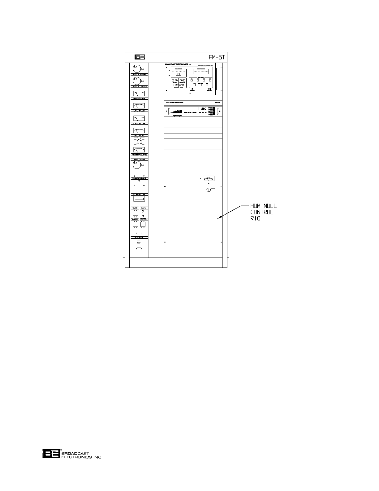
COPYRIGHT 1997 BROADCAST ELECTRONICS, INC
597-0033-401
FIGURE 5-2. HUM NULL CONTROL LOCATION
5-38. SECOND HARMONIC SUPPRESSOR. Adjustment of the second harmonic suppressor in
the field will not normally be required, even if the PA tube is replaced. Adjustment should
be attempted only when absolutely necessary. Misadjustment of the suppressor could re
sult in sporadic operation, possibly damaging the PA tube, the cavity, or the low-pass filter.
It is suggested the customer contact the Broadcast Electronics Customer Service Depart
ment before attempting this adjustment. If it is certain that adjustment of the second har
monic suppressor is required, proceed as follows.
5-39. Required Equipment. The following equipment is required to complete adjustment of the
second harmonic suppressor.
A. 1/16 inch (1.6 mm) hex wrench.
B. Tektronix Model 492 Spectrum Analyzer or the equivalent capable of displaying
frequencies at twice the transmitter frequency of operation.
C. 50 Ohm 10 dB resistive attenuator pad, BNC jack to BNC plug (Texscan FP-50).
D. A cable for the spectrum analyzer comprising the following:
1. 10 feet (3.05 m) of Belden RG 58A/U coaxial cable (BE P/N 622-0050).
2. Two BNC plugs (Pomona UG88/U--BE P/N 417-0205).
E. Six inch scale.
WARNING: DISCONNECT POWER PRIOR TO SERVICING
5-6
Page 68

WARNING
NEVER OPEN THE EQUIPMENT UNLESS ALL TRANS
MITTER PRIMARY POWER IS DISCONNECTED. USE
WARNING
THE GROUNDING STICK PROVIDED TO ENSURE ALL
COMPONENTS AND ALL SURROUNDING COMPO
NENTS ARE DISCHARGED BEFORE ATTEMPTING ANY
MAINTENANCE.
5-40. Procedure. To adjust the second harmonic suppressor, proceed as follows.
5-41. Deenergize all primary power to the transmitter.
5-42. Open the cabinet rear door.
5-43. Connect one end of the spectrum analyzer cable (Item D) to the RF sample port (J2) on the
elbow near the cavity.
5-44. Connect the attenuator pad (Item C) in series with the cable and attach the attenuator pad
to the spectrum analyzer input.
5-45. Close the cabinet rear door.
5-46. Energize the transmitter primary ac input.
5-47. Operate the transmitter at the normal power output and ensure all PA stage tuning and
loading controls are correctly adjusted.
5-48. Record the level of the second harmonic displayed on the spectrum analyzer
.
WARNING
DISCONNECT ALL TRANSMITTER PRIMARY POWER
BEFORE PROCEEDING.
WARNING
5-49. Disconnect all transmitter primary power.
5-50. Open the cabinet rear door.
5-51. Loosen the two hex-head lock-screws securing the second harmonic suppressor adjust
ment rod very slightly--just enough to allow in and out adjustment (see Figure 5-3).
CAUTION
THE SECOND HARMONIC SUPPRESSOR IS ADJUSTED
BY SLIDING THE ADJUSTMENT ROD IN OR OUT. DO
CAUTION
NOTE
NOT ROTATE THE ROD.
THE ORIGINAL HARMONIC SUPPRESSOR ADJUST
MENT DIMENSION IS RECORDED ON THE FACTORY
NOTE
FINAL TEST DATA SHEETS IF THE DIMENSION MUST
BE REFERENCED.
5-52. Move the second harmonic suppressor adjustment rod slightly (approximately 1/16 inch).
Record the amount moved and the direction(in or out) . Slightly tighten
the two screws to secure the rod in place.
WARNING: DISCONNECT POWER PRIOR TO SERVICING
5-7
Page 69
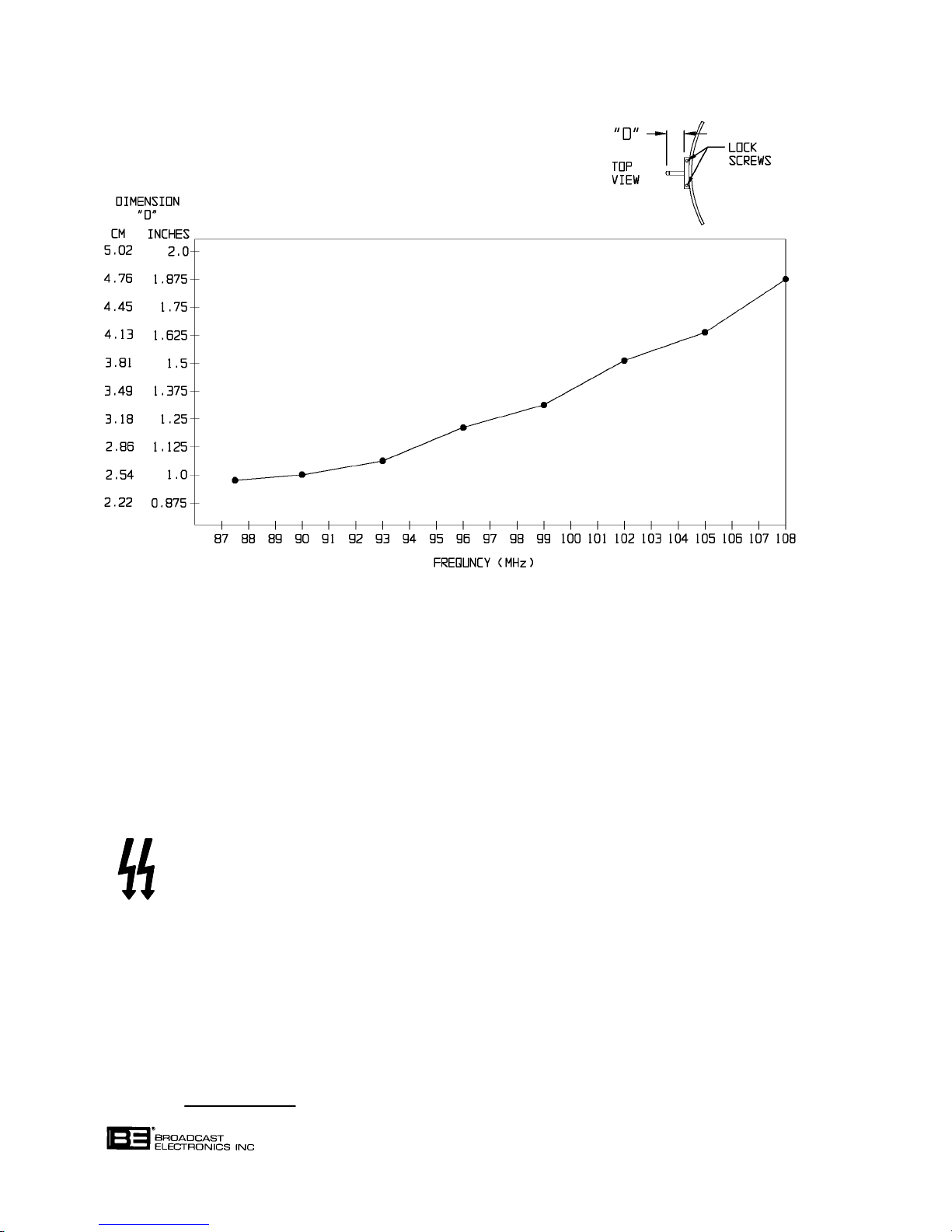
COPYRIGHT 1997 BROADCAST ELECTRONICS, INC
597-0033-33
FIGURE 5-3. SECOND HARMONIC SUPPRESSOR COARSE SETTING
5-53. Close the cabinet rear door.
5-54. Energize the transmitter primary ac input and operate the transmitter at the normal
power output.
5-55. Repeat paragraphs 5-49 through 5-55, moving the second harmonic suppressor adjust
ment rod slightly in or out as required to minimize the second harmonic indication.
WARNING
WARNING
5-56. After the correct setting of the second harmonic suppressor is determined, disconnect all
transmitter primary power.
5-57. Open the cabinet rear door.
5-58. Secure both hex-head lock-screws on the second harmonic suppressor bushing (see Figure
5-3).
5-59. Disconnect the spectrum analyzer cable from J2 on the transmission line.
5-60. Close the cabinet rear door. Record the new harmonic suppressor dimension here
.
WARNING: DISCONNECT POWER PRIOR TO SERVICING
DISCONNECT ALL TRANSMITTER PRIMARY POWER
BEFORE PROCEEDING.
5-8
Page 70

5-61. NEUTRALIZATION. PA neutralization in the field will not normally be required, even if
the PA tube is replaced. If it is certain that adjustment of the neutralization circuitry is
required, proceed as follows.
CAUTION
INCORRECT NEUTRALIZATION CAN RESULT IN IN
STABILITY WHICH COULD DAMAGE THE PA TUBE,
CAUTION
CAVITY, OR LOW-PASS FILTER. CONSULT THE FAC
TORY BEFORE ATTEMPTING NEUTRALIZATION.
5-62. Required Equipment. The following equipment is required to complete PA neutralization.
A. Spectrum analyzer (Tektronix Model 492 or equivalent).
B. 25 Watt, 50 Ohm RF attenuator/termination with -20 dB sample output, type N
receptacles (Bird Model 8340-030 or equivalent).
C. Two locally fabricated cables, each comprising the following:
1. 24 inches (61 cm) of Belden RG 58A/U coaxial cable (BE P/N 622-0050).
2. Two BNC plugs (Pomona UG88/U--BE P/N 417-0205).
D. Three adapters, BNC receptacle to type N plug (Pomona UG201A/U--BE P/N
417-3288).
E. No. 2 Phillips screwdriver, 4-inch (10.2 cm) blade.
F. Flat-tip screwdriver, 4-inch (10.2 cm) blade and 1/4 inch (0.64 cm) tip.
G. Exciter line cord, P/O exciter accessory pack--BE P/N 682-0001).
H. Electrical extension cord, 3-wire, 12 feet (3.7 m) long;
I. Six-inch scale, graduated in sixty-fourths of an inch.
5-63. Procedure. To adjust PA neutralization, proceed as follows:
5-64. Operate the transmitter at the normal power output and ensure all PA stage tuning and
loading controls are correctly adjusted.
5-65. Secure the INPUT TUNING, OUTPUT LOADING, and OUTPUT TUNING control
knobs in position with tape. The controls must not be moved until the entire procedure has
been completed.
WARNING
ENSURE ALL TRANSMITTER PRIMARY POWER IS DIS
CONNECTED BEFORE OPENING THE EQUIPMENT.
WARNING
5-66. Deenergize all primary power to the transmitter.
5-67. Open the cabinet door.
5-68. Disconnect the coaxial cable from the exciter RF OUTPUT connector.
5-69. Connect a BNC-to-type N adapter on each of the RF termination connectors.
5-70. Disconnect the cable from the PA RF INPUT (J1) connector.
5-71. Connect one cable and one BNC-to-type N adapter between the PA RF INPUT (J1) con
nector and the RF termination -20 dB output.
WARNING: DISCONNECT POWER PRIOR TO SERVICING
5-9
Page 71

5-72. Connect one cable between the exciter RF OUTPUT connector and the input to the RF ter
mination.
5-73. Disconnect wire No. 5 from TB1-7 on the rear of the exciter and connect a temporary wire
jumper from TB1-6 to TB1-7. Flag the temporary jumper with a piece of tape marked
TEMPORARY".
5-74. Disconnect the line cord plug and remove the fuse from the AC LINE VOLTAGE SELEC
TOR on the exciter rear panel. Cover the line cord plug with a piece of tape marked 240
VOLTS".
5-75. Remove the AC LINE VOLTAGE SELECTOR circuit board with a small pair of needle-
nose pliers and record the circuit board voltage indication
circuit board so that 115/120V" is visible when the circuit board is inserted into the recep
tacle.
5-76. Replace the fuse with a slow-blow type rated at 10 Amperes.
5-77. Connect the accessory exciter line cord to the extension cord. Route the extension cord out
through the top or bottom of the cabinet to a source of 110 to 120 Vac.
5-78. Connect the accessory exciter line cord (item G) to the exciter.
. Reinsert the
WARNING
PRIMARY TRANSMITTER POWER MUST REMAIN OFF
THROUGHOUT THE FOLLOWING PROCEDURE.
WARNING
5-79. Assure that the exciter is operating independently of the transmitter.
5-80. Connect the spectrum analyzer to the RF sample port (J2) in the transmitter output trans
mission line. Adjust the analyzer to obtain a reference level display and position the ana
lyzer so that it may be viewed from the rear of the transmitter.
5-81. Note the position of the grounding stick in the rear of the cabinet.
WARNING
USE THE GROUNDING STICK PROVIDED TO ENSURE
NO PA TUBE POTENTIALS ARE PRESENT IN THE FOL
WARNING
LOWING STEP BY GROUNDING THE PA TUBE PLATE
AND SCREEN CONNECTIONS BEFORE PROCEEDING.
5-82. Open the PA cavity access door and ground the PA tube plate and screen connections to
ensure no potentials are present in the cavity before attempting to touch anything within
the cavity.
5-83. After it has been determined that no PA tube potentials are present, mark the position of
the eight neutralization adjustments, (refer to Figure 5-4). Correct neutralization will be
found near the original factory position (refer to Figure 5-4).
WARNING
WARNING
5-84. Loosen the six screws (A, Figure 5-4) on top of each capacitor slightly--just enough to al
low adjustment of each pair of inductors. When the neutralization procedure is properly
completed, the height of all inductors will be approximately the same, within 1/16 inch
(0.16 cm).
WARNING: DISCONNECT POWER PRIOR TO SERVICING
BE CAREFUL WHEN ADJUSTING THE NEUTRALIZA
TION STRAPS WITH FINGERS AS THE EDGES OF
THE MATERIAL ARE VERY SHARP.
5-10
Page 72
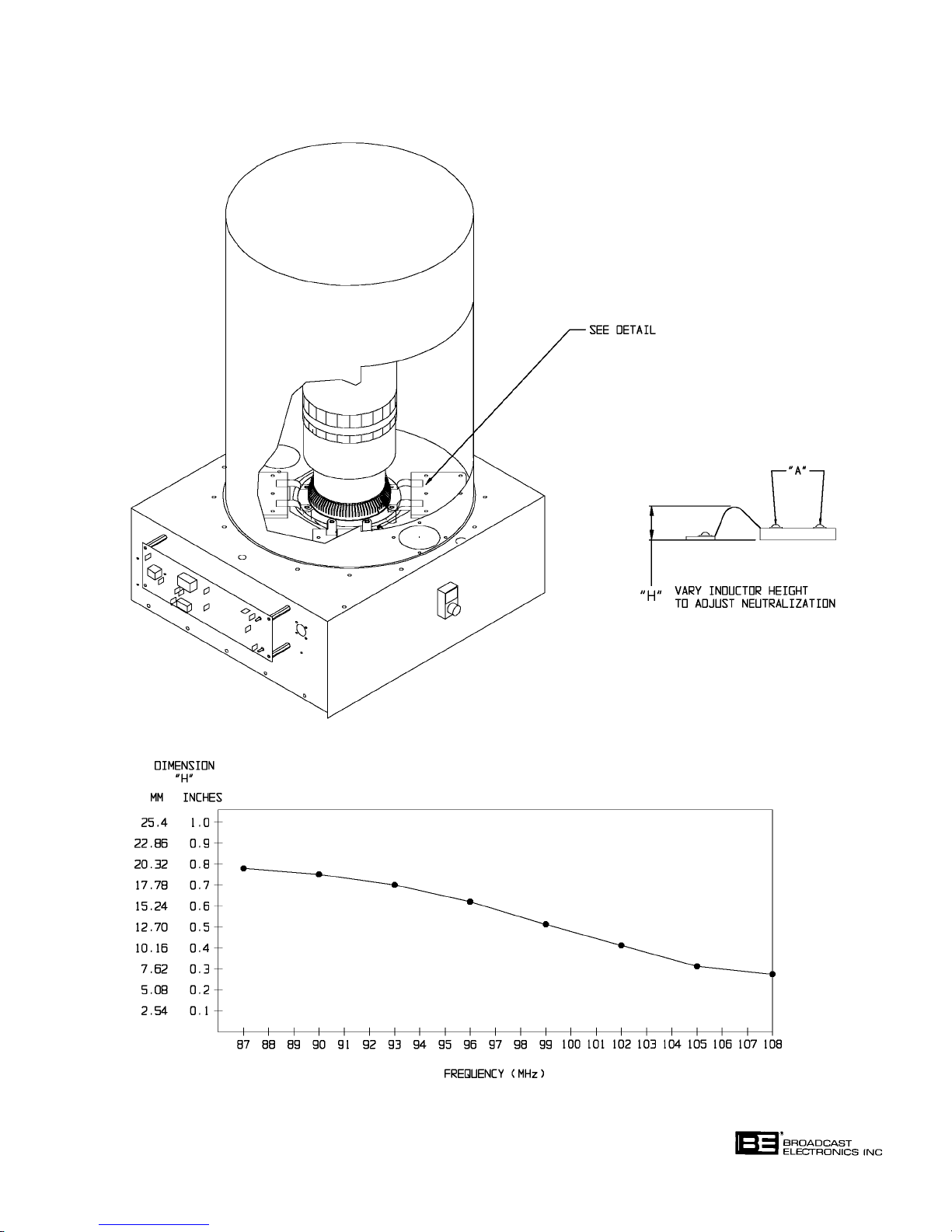
FIGURE 5-4. NEUTRALIZATION STRAP COARSE SETTING
WARNING: DISCONNECT POWER PRIOR TO SERVICING
COPYRIGHT 1997 BROADCAST ELECTRONICS, INC
597-0032-35
5-11
Page 73

5-85. Neutralization is adjusted in the following manner:
A. Remove all foreign objects from the cavity then close the cavity access door.
B. Note the spectrum analyzer indication.
C. Open the cavity access door and adjust one pair of inductors very slightly. The in-
ductors must be adjusted in pairs. Lightly secure the six screws on the capacitor
plate.
D. Remove all foreign objects from the cavity and close the cavity access door.
E. Note the change in the spectrum analyzer indication.
F. Repeat steps A through E until a minimum spectrum analyzer indication is noted.
G. Repeat steps A through F for the remaining inductor pairs to minimize the spec-
trum analyzer indication.
H. Secure the six screws in each capacitor. When the neutralization procedure is
properly completed, the height of all inductors will be approximately equal.
I. Ensure all four capacitors are secure before closing the cavity access door.
5-86. Close and latch the cavity access door. Replace the grounding stick on the hanger.
5-87. Disconnect the spectrum analyzer from the output transmission line.
CAUTION
DO NOT CONNECT THE EXCITER TO THE LINE CORD
WIRED INTO THE TRANSMITTER IN THE FOLLOWING
CAUTION
WARNING
STEP.
DISCONNECT ALL EXCITER PRIMARY POWER BE
FORE PROCEEDING.
WARNING
5-88. Remove the electrical extension cord and exciter line cord. Do not connect the exciter to
the line cord wired into the transmitter at this time.
5-89. Remove the fuse from the exciter rear panel AC LINE VOLTAGE SELECTOR.
5-90. Remove the AC LINE VOLTAGE SELECTOR circuit board with a small pair of needle-
nose pliers. Reinsert the circuit board so that the voltage recorded in the preceding text is
visible when the circuit board is inserted into the receptacle.
5-91. Replace the fuse with a slow-blow type rated at 5 Amperes.
5-92. Remove the tape from the exciter line cord and connect the plug to the exciter.
5-93. Remove the temporary wire jumper from TB1 on the exciter rear panel and reconnect wire
No. 5 to TB1-7.
5-94. Remove the cabling and test load connected between the exciter RF OUTPUT connector
and the PA RF INPUT (J1) connector. Remove the adapter from the PA RF INPUT (J1)
connector.
5-95. Reconnect the exciter to the PA input.
WARNING: DISCONNECT POWER PRIOR TO SERVICING
5-12
Page 74

5-96. TRANSMITTER POWER LEVEL CHANGE.
WARNING
NEVER OPEN THE EQUIPMENT UNLESS ALL TRANS
MITTER PRIMARY POWER IS DISCONNECTED. USE
WARNING
THE GROUNDING STICK PROVIDED TO ENSURE ALL
COMPONENTS AND ALL SURROUNDING COMPO
NENTS ARE DISCHARGED BEFORE ATTEMPTING
MAINTENANCE ON ANY AREA WITHIN THE TRANS
MITTER.
5-97. Each transmitter is programmed, operated, and tested at a specific power level at the fac
tory prior to shipment. If at a future date the transmitter is to be operated at a power level
other than the original factory programmed level, the following transmitter parameters
must be checked and adjusted if required to assure proper transmitter operation. If prob
lems occur during initial operation, contact the Broadcast Electronics Customer Service
Department for additional service procedures.
A. Refer to SECTION III, OPERATION and reset the APC operating reference.
B. Energize the transmitter primary ac power and operate the transmitter. Adjust
the input tuning control for a minimum exciter reflected power indication on the
multimeter (for high reflected power conditions, use the multimeter grid current
function and maximum grid current information for indications of correct tuning
operations).
C. Refer to CONTROLLER SECTION II, MAINTENANCE and perform the
FORWARD POWER CALIBRATION and REFLECTED POWER CALIBRATION
adjustment procedures.
5-98.
TRANSMITTER FREQUENCY CHANGE PROCEDURE.
CAUTION
CONSULT THE FACTORY BEFORE ATTEMPTING TO
CHANGE THE TRANSMITTER OPERATING FRE
CAUTION
5-99. GENERAL. The following text presents an overall procedure to change the transmitter op
erating frequency. The procedure specifies operational adjustment procedures located
throughout this publication and FM-250C publication 597-1004. To change the transmit
ter operating frequency, proceed as follows.
5-100. Procedure. To change the transmitter operating frequency, proceed as follows:
WARNING
QUENCY.
NEVER OPEN THE EQUIPMENT UNLESS ALL TRANS
MITTER PRIMARY POWER IS DISCONNECTED. USE
WARNING
THE GROUNDING STICK PROVIDED TO ENSURE ALL
COMPONENTS AND ALL SURROUNDING COMPO
NENTS ARE DISCHARGED BEFORE ATTEMPTING
MAINTENANCE ON ANY AREA WITHIN THE TRANS
MITTER.
WARNING
DISCONNECT ALL TRANSMITTER PRIMARY POWER
BEFORE PROCEEDING.
WARNING
5-101. Disconnect all transmitter primary power. The primary ac power must remain OFF unless
specified by an adjustment procedure.
WARNING: DISCONNECT POWER PRIOR TO SERVICING
5-13
Page 75

5-102. Refer to Figure 5-5A and adjust the transmitter coarse output tuning by raising or lower
ing the PA tuning line on top of the PA cavity. Refer to Figure 5-5B and coarse adjust the
transmitter input tuning cyclometers.
5-103. Refer to Figure 5-3 and coarse adjust the transmitter second harmonic suppressor. The
suppressor is adjusted by loosening the two hex-head lock screws and moving the adjust
ment rod in or out as required. Do not rotate the rod during adjustment.
5-104. Refer to Figure 5-4 and coarse adjust the transmitter neutralization.
5-105. Refer to FM-250C publication 597-1004, PART II SECTION IV, AFC/PLL ASSEMBLY
and perform the FREQUENCY SELECTION procedure. Operate and test the exciter inde
pendently from the transmitter.
5-106. Refer to SECTION II, INSTALLATION and perform the PRELIMINARY OPERATION
AND TUNING procedure to obtain a 10% power indication from the transmitter. Use a
spectrum analyzer to monitor spurious activity during tuning. Also, use an in-line watt
meter connected to the transmitter output transmission line for all power output indica
tions.
5-107. Refer to the adjustment procedures in the preceding text and perform the NEUTRALIZA
TION procedure.
5-108. Refer to SECTION II, INSTALLATION and complete the PRELIMINARY OPERATION
AND TUNING procedure to obtain a 100% power indication from the transmitter.
5-109. Refer to the adjustment procedures in the preceding text and perform the SECOND HAR
MONIC SUPPRESSOR adjustment procedure.
5-110. Refer to CONTROLLER SECTION II, MAINTENANCE and perform the FORWARD
POWER CALIBRATION and REFLECTED POWER CALIBRATION adjustment proce
dures.
5-111.
TROUBLESHOOTING.
WARNING
NEVER OPEN THE EQUIPMENT UNLESS ALL TRANS
MITTER PRIMARY POWER IS DISCONNECTED. USE
WARNING
THE GROUNDING STICK PROVIDED TO ENSURE ALL
COMPONENTS AND ALL SURROUNDING COMPO
NENTS ARE DISCHARGED BEFORE ATTEMPTING
MAINTENANCE ON ANY AREA WITHIN THE TRANS
MITTER.
5-112. Most troubleshooting consists of visual checks. Due to the dangerous voltages and high
currents in the equipment, it is considered hazardous to work with power energized.
Therefore, the various transmitter indicators (meters, LEDs, fuses, and circuit breakers)
should be used to isolate the malfunction to one of the specific areas listed below. Typical
meter indications are presented in Table 5-1 and transmitter primary power demand re
quirements are listed in Table 5-2.
TRANSMITTER TROUBLESHOOTING AREAS
A. Power Supplies
B. Exciter
C. Power Amplifier
D. Transmitter Controller
E. Transmitter Load
WARNING: DISCONNECT POWER PRIOR TO SERVICING
5-14
Page 76
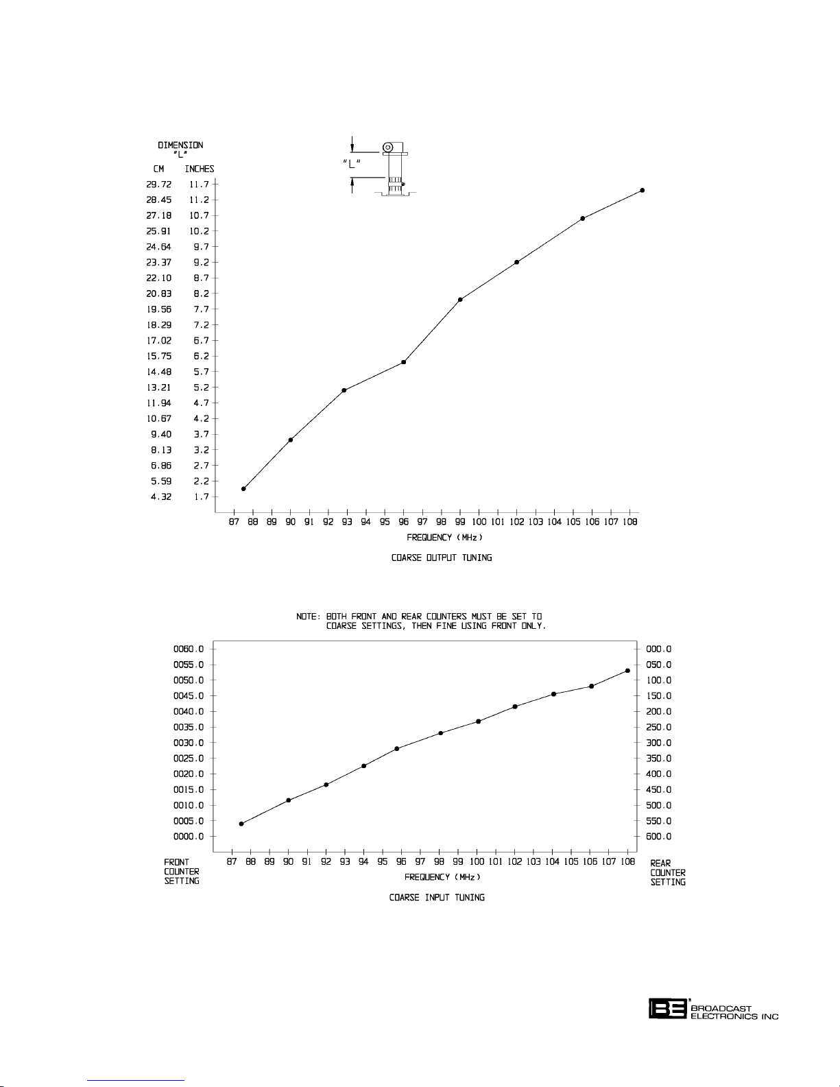
FIGURE 5-5. COARSE TUNING ADJUSTMENTS
WARNING: DISCONNECT POWER PRIOR TO SERVICING
COPYRIGHT 1997 BROADCAST ELECTRONICS, INC
597-0033-25
5-15
Page 77

TABLE 5-1. TYPICAL METER INDICATIONS (5 kW RF OUTPUT)
METER SWITCH POSITION/INDICATION
FM-5T
VSWR FWD
OUTPUT POWER LESS THAN 1.2 100%
PLATE CURRENT 1.3 A
PLATE VOLTAGE 5300 V
SCREEN VOLTAGE 525 V
SCREEN CURRENT 60 mA
GRID VOLTAGE -260 V
GRID CURRENT 45 mA
FILAMENT VOLTAGE 5.0 V
EXCITER FORWARD POWER 140 W
FM-5TS
VSWR FWD
OUTPUT POWER LESS THAN 1.2 100%
PLATE CURRENT 1.3 A
PLATE VOLTAGE 5300 V
SCREEN VOLTAGE 525 V
SCREEN CURRENT 60 mA
GRID VOLTAGE -260 V
GRID CURRENT 45 mA
FILAMENT VOLTAGE 5.0 V
EXCITER FORWARD POWER 140 W
TABLE 5-2. TYPICAL POWER DEMAND (5 kW RF OUTPUT)
FM-5T
AC Line Frequency 60 Hz 50 Hz 50 Hz
AC Line Voltage 210 V 224 V 380 V
AC Line Current 28 A 28 A 16 A
FM-5TS
AC Line Frequency 60 Hz 50 Hz 50 Hz
AC Line Voltage 210 V 224 V 380 V
AC Line Current 48 A 48 A 28 A
WARNING: DISCONNECT POWER PRIOR TO SERVICING
5-16
Page 78

CAUTION
CAUTION
MANY COMPONENTS IN THE TRANSMITTER ARE
MOUNTED TO HEAT SINKS UTILIZING A FILM OF
HEAT-SINK COMPOUND FOR THERMAL CONDUC
TION.
CAUTION
IF ANY SUCH COMPONENT IS REPLACED, ENSURE A
THIN FILM OF A ZINC-BASED HEAT-SINK
CAUTION
COMPOUND IS USED (BE P/N 700-0028) TO ASSURE
GOOD HEAT DISSIPATION.
5-113. Once the trouble is isolated, refer to the applicable assembly publication in Part II of this
manual discussing the theory of operation and providing troubleshooting for the respective
assembly to assist in problem resolution. Figures 5-6 through 5-10 provide drawings to
assist component location.
5-114.
5-115. On all circuit boards, the adhesive securing the copper track to the board melts at almost
5-116. To remove a component from a circuit board, cut the leads from the body of the defective
COMPONENT REPLACEMENT ON CIRCUIT BOARDS. All the FM-5T/FM-5TS trans
mitter circuit boards are double-sided boards with plated through-holes with the excep
tion of the transmitter controller main and front panel circuit boards. Due to the doublesided design, the components on the circuit boards can be replaced without damage if stan
dard soldering techniques are used. The FM-5T/FM-5TS transmitter controller main and
front-panel circuit boards are constructed using surface mount technology. Therefore,
components on the controller main circuit and front-panel circuit boards can not be replaced without destruction of the circuit board traces.
the same temperature at which solder melts. A circuit board track can be destroyed by ex
cessive heat or lateral movement during soldering. Use of a small iron with steady pres
sure is required for circuit board repairs.
component while the device is still soldered to the board.
5-117. Grip each component lead, one at a time, with long nose pliers. Turn the board over and
touch a soldering iron to the lead at the solder connection. When the solder begins to melt,
push the lead through the back side of the board and cut off the bent-over outer end of the
lead. Each lead may now be heated independently and pulled out of each hole. The holes
may be cleared of solder by carefully re-heating with a low wattage iron and removing the
residual solder with a soldering vacuum tool.
5-118. Install the new component and apply solder from the bottom side of the board. If no dam
age has been done to the plated through-holes, soldering of the top side is not required.
5-17
WARNING: DISCONNECT POWER PRIOR TO SERVICING
Page 79

WARNING
WARNING
MOST SOLVENTS WHICH WILL REMOVE ROSIN FLUX
ARE VOLATILE AND TOXIC BY THEIR NATURE AND
SHOULD BE USED ONLY IN SMALL AMOUNTS IN A
WELL VENTILATED AREA, AWAY FROM FLAME, IN
CLUDING CIGARETTES AND A HOT SOLDERING
IRON.
WARNING
OBSERVE THE MANUFACTURER'S CAUTIONARY IN
STRUCTIONS.
WARNING
5-119. After soldering, remove flux with a cotton swab moistened with a suitable solvent. Rub
bing alcohol is highly diluted and is not effective. Solvents are available in electronic sup
ply house which are useful.
5-120. The board should be checked to ensure the flux has been removed and not just smeared
about. Rosin flux is not normally corrosive, but rosin will absorb enough moisture in time
to become conductive and cause problems.
WARNING: DISCONNECT POWER PRIOR TO SERVICING
5-18
Page 80
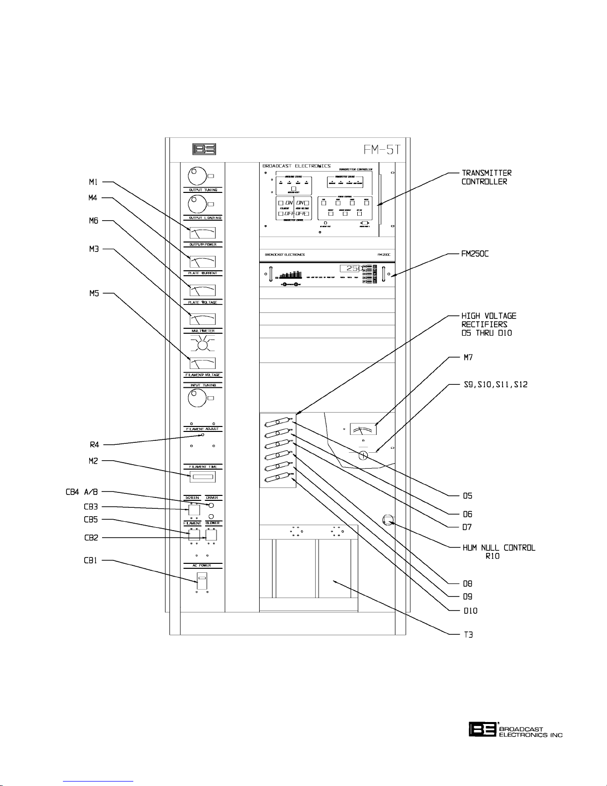
FIGURE 5-6. FM-5T CABINET COMPONENT LOCATOR, FRONT
WARNING: DISCONNECT POWER PRIOR TO SERVICING
COPYRIGHT 1997 BROADCAST ELECTRONICS, INC
597-0033-402
5-19
Page 81
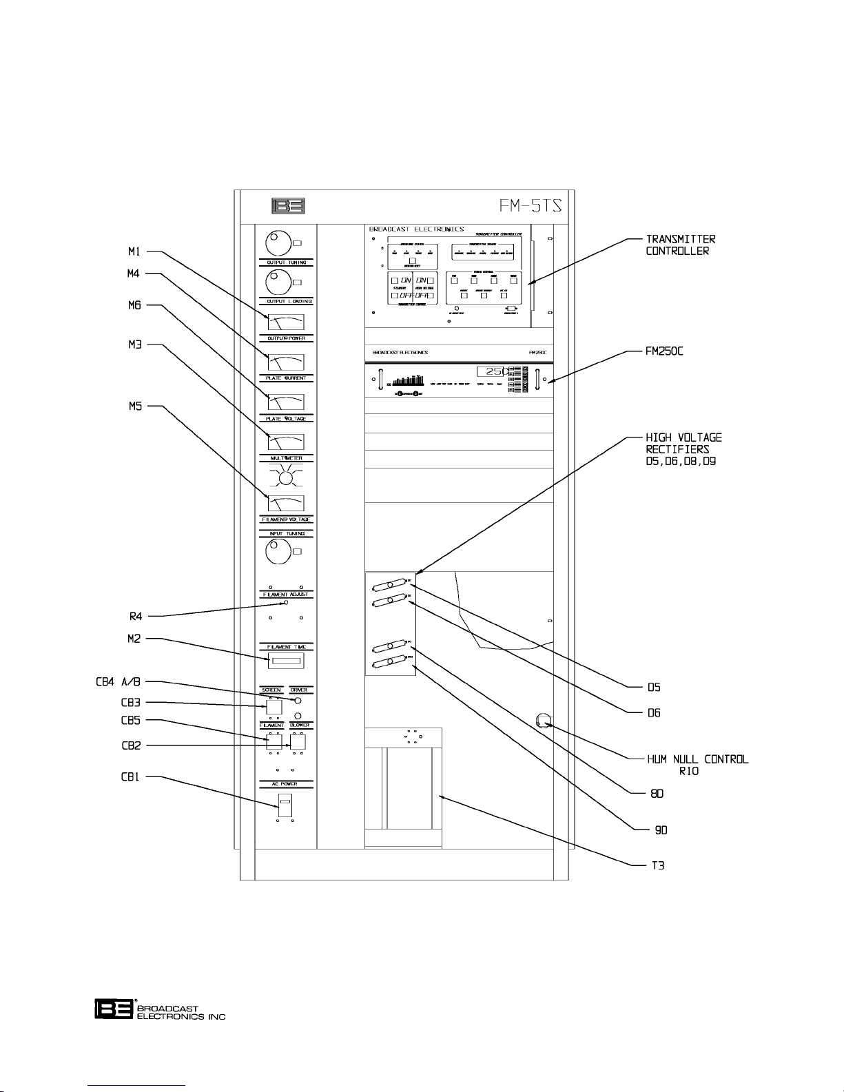
FIGURE 5-7. FM-5TS CABINET COMPONENT LOCATOR, FRONT
WARNING: DISCONNECT POWER PRIOR TO SERVICING
COPYRIGHT 1997 BROADCAST ELECTRONICS, INC
597-0033-403
5-20
Page 82
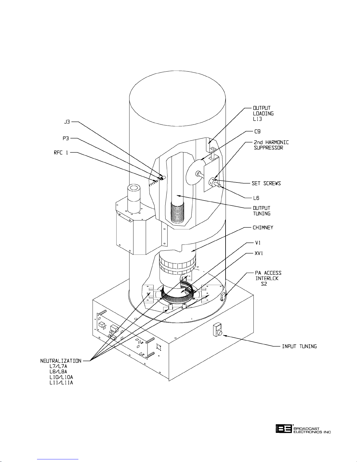
FIGURE 5-8. PA CAVITY COMPONENT LOCATOR
WARNING: DISCONNECT POWER PRIOR TO SERVICING
COPYRIGHT 1997 BROADCAST ELECTRONICS, INC
597-0033-404
5-21
Page 83

BLANK PAGE
WARNING: DISCONNECT POWER PRIOR TO SERVICING
5-22
Page 84
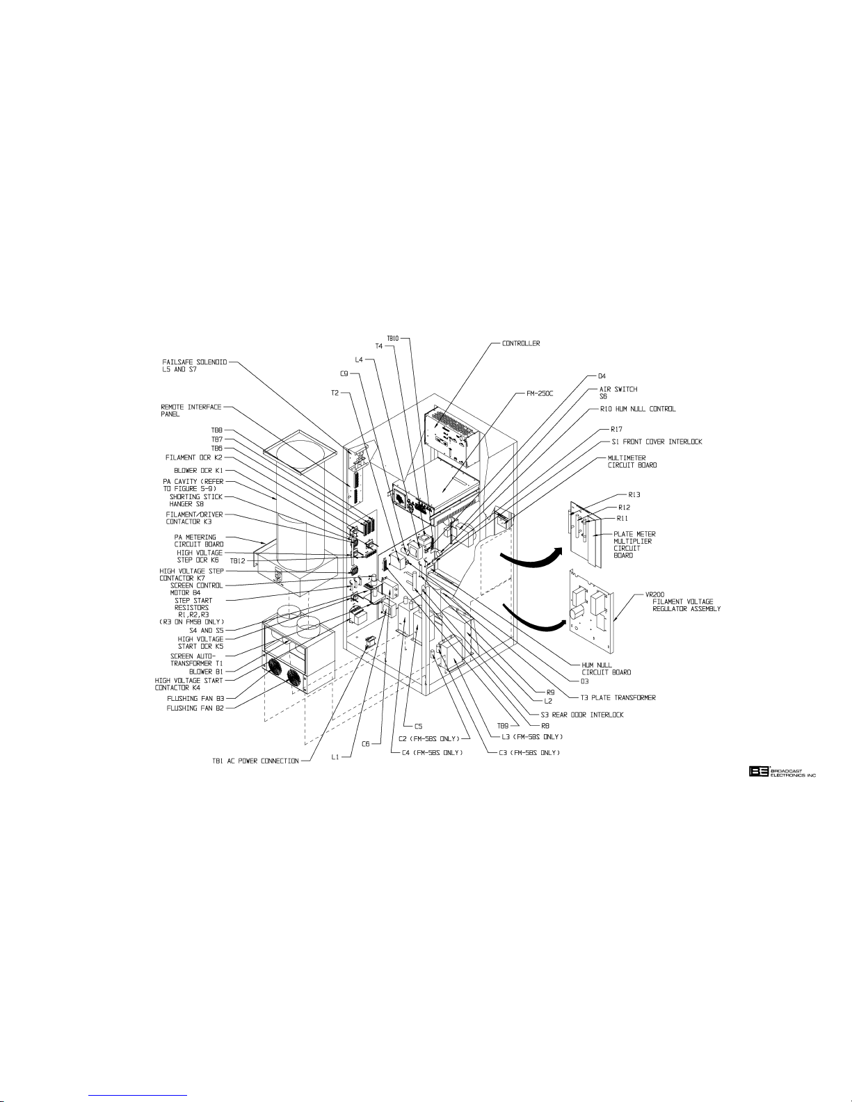
WARNING: DISCONNECT POWER PRIOR TO SERVICING
597-0033-405
FIGURE 5-9.
FM-5T/FM-5TS CABINET COMPONENT
LOCATOR, REAR
(5-23/5-24)
COPYRIGHT 1997 BROADCAST ELECTRONICS, INC
Page 85
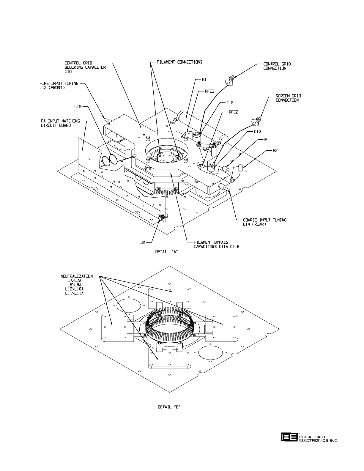
WARNING: DISCONNECT POWER PRIOR TO SERVICING
COPYRIGHT 1997 BROADCAST ELECTRONICS, INC
597-0033-40
FIGURE 5-10. PA TUBE SOCKET
5-25
Page 86

SECTION VI
PARTS LIST
6-1. INTRODUCTION.
6-2. This section provides descriptions and part numbers of electrical components, assemblies,
and selected mechanical parts required for maintenance of the Broadcast Electronics
FM-5T and FM-5TS FM Transmitters. Each table entry in this section is indexed by ref
erence designators appearing on the applicable schematic diagram. Parts for the transmit
ter controller are listed in the CONTROLLER section of this manual.
TABLE 6-1. REPLACEABLE PARTS LIST INDEX
(Sheet 1 of 2)
TABLE DESCRIPTION PART NO. PAGE
6-2 FM-5T TRANSMITTER ASSEMBLY 909-5000-215/ 6-3
-315
-385
6-3 FM-5TS TRANSMITTER ASSEMBLY 909-5000-255/ 6-3
-355
6-4 SCREEN AND BIAS PANEL ASSEMBLY 959-0271-001 6-5
6-5 HUM NULL ASSEMBLY 919-0063 6-5
6-6 BLEEDER PANEL ASSEMBLY 959-0271-003 6-5
6-7 METER MULTIPLIER CIRCUIT BOARD, FM-5T 919-0200 6-6
6-8 METER MULTIPLIER CIRCUIT BOARD, FM-5TS 919-0079 6-6
6-9 METER PANEL ASSEMBLY 959-0271-105 6-6
6-10 MULTIMETER CIRCUIT BOARD ASSEMBLY 919-0049-001 6-7
6-11 PLATE CURRENT METER ASSEMBLY 959-0300 6-7
6-12 METER PROTECTION CIRCUIT BOARD ASSEMBLY 919-0109-002 6-7
6-13 FAN/BLOWER ASSEMBLY 959-0271-006 6-7
6-14 DIODE STACK PANEL ASSEMBLY, FM-5T 959-0271-008 6-7
6-15 DIODE STACK PANEL ASSEMBLY, FM-5TS 959-0271-004 6-8
6-16 CONTACTOR PANEL ASSEMBLY, FM-5T 959-0271-109 6-8
6-17 CONTACTOR PANEL ASSEMBLY, FM-5TS 959-0271-102 6-8
6-18 OPTICALLY-COUPLED-RELAY (OCR) ASSEMBLY 919-0096 6-9
6-19 POWERSTAT ASSEMBLY 959-0121 6-9
6-20 THREE-PHASE VOLTMETER ASSEMBLY 959-0271-010 6-9
6-21 PA METERING CIRCUIT BOARD ASSEMBLY 919-0048-008 6-10
6-22 BASIC UNIT CABLE ASSEMBLY 949-0161-100 6-11
6-23 GROUND STICK HANGER ASSEMBLY 955-0038 6-12
6-24 DIRECTIONAL COUPLER ASSEMBLY, 40 db (RFL) 959-0082-040 6-12
6-25 DIRECTIONAL COUPLER ASSEMBLY, 45 db (FWD) 959-0082-045 6-12
6-26 REMOTE INTERFACE PANEL ASSEMBLY 959-0117-100 6-12
6-27 FAIL-SAFE SOLENOID ASSEMBLY 959-0083 6-12
6-1
Page 87

TABLE 6-1. REPLACEABLE PARTS LIST INDEX
(Sheet 2 of 2)
TABLE DESCRIPTION PART NO. PAGE
6-28 REMOTE INTERFACE CIRCUIT BOARD ASSEMBLY 919-0439 6-12
6-29 TUBE SOCKET AND INPUT TUNING ASSEMBLY 959-0151 6-13
6-30 INPUT MATCHING CIRCUIT BOARD ASSEMBLY 919-0064 6-13
6-31 RF ENCLOSURE ASSEMBLY 959-0272 6-13
6-32 PA CHIMNEY ASSEMBLY 959-0272-002 6-13
6-33 TRANSMISSION LINE ASSEMBLY 959-0272-003 6-14
6-34 SHIELD CELL/TUNING LINE ASSEMBLY 959-0272-101 6-14
6-35 EXHAUST AIR TEMPERATURE CIRCUIT BOARD 919-0082 6-14
ASSEMBLY
6-36 ACCESSORY PARTS KIT 969-0013 6-14
6-2
Page 88

TABLE 6-2. FM-5T TRANSMITTER - 909-5000-215/-315/-385
REF. DES. DESCRIPTION PART NO. QTY.
C5 Capacitor, Electrolytic, 4 uF, 8 kV, Non-PCB Oil/ Paper 047-0004 1
CB1 Circuit Breaker, 40 Amperes, 3-Pole, 240V (AC POWER) 341-0027 1
L2 Choke, Filter, 6.8 H, 1.8 A Continuous 361-0001 1
FOR 50 Hz TRANSMITTER MODELS ONLY
M2 Meter, 0 - 99,999.9 Hour, Non-Resettable, 230 Volt, 310-0000-003 1
S1, S3 Interlock Switch, SPDT, 15A @ 125V ac, 0.5A @ 125V dc, 346-3302 2
S6 Switch, Pressure, 120-480V ac 60 Hz, 15 Amperes 340-0011 1
T3 Transformer, Plate 3 0
TB1 Terminal Strip, Consisting of:
V1 Tube, 4CX3500A EIMAC/SVETLANA 243-3500 1
---- Transformer/Regulator, Filament 370-0056 1
---- Counting Dial, 0-9999, 100 Turn 290-0002 1
---- Air Filter, 16 X 20 X 1 Inch (40.64 X 50.8 X 2.54 cm) 407-0062 1
---- FM-250C Exciter, 50 TO 250 Watt, 220V 909-0251-304 1
---- Screen And Bias Panel Assembly 959-0271-001 1
---- Bleeder Panel Assembly 959-0271-003 1
---- Meter Panel Assembly, FM-5T 959-0271-105 1
---- Fan and Blower Assembly 959-0271-006 1
---- Diode Stack Panel Assembly 959-0271-008 1
---- Contactor Panel Assembly 959-0271-109 1
---- Three-Phase Voltmeter Assembly 959-0271-010 1
---- PA Metering Circuit Board Assembly, FM-5T 919-0048-008 1
----- Basic Unit Cable Assembly, FM-5T 949-0161-100 1
---- Final Unit Cable Assembly 949-0163 1
---- Ground Stick Hanger Transmitter Assembly 955-0038 1
---- Directional Coupler Assembly, 40DB (RFL) 959-0082-040 1
---- Directional Coupler Assembly, 45DB (FWD) 959-0082-045 1
---- Remote Interface Panel Assembly, FM-10T/FM-5T 959-0117-100 1
---- Ground Stick Shorting Assembly 959-0145 1
---- Tube Socket And Input Tuning Assembly 959-0151 1
---- RF Enclosure Assembly 959-0272 1
---- Transmission Line Assembly 959-0272-003 1
---- Shield Cell/Tuning Line Assembly, FM-5T/FM-10T 959-0272-101 1
---- FM Transmitter Digital Controller Assembly 959-0430 1
---- Accessory Parts Kit 969-0013 1
3.5 Inch (8.89 cm) (FILAMENT TIME Meter)
0.25A @ 250V dc
Primary: 208/240V
346V to 433, Wye Connected
Secondary: 2300V @ 1.4 Amperes Continuous, Wye Connected
Terminal Block 412-0041 4
End Clamp 412-0042-001 2
Ground Barrier 412-0043 1
Mounting Channel, 2.76 Inches (7 cm) 412-0044 3
, 50/60 Hz 376-0115 1
±11V ac, Delta Connected;
TABLE 6-3. FM-5TS TRANSMITTER - 909-5000-255/-355
REF. DES. DESCRIPTION PART NO. QTY.
C2, C3 Capacitor, Polypropylene Film, 0.97 uF ±5%, 2500 VRMS @ 120 Hz 047-0006 2
C4, C5 Capacitor, Electrolytic, 4 uF, 8 kV, Non-PCB Oil/Paper 047-0004 2
CB1 Circuit Breaker, 2-Pole, 240V, 60 Amps 341-0050 1
(Sheet 1 of 2)
6-3
Page 89

TABLE 6-3. FM-5TS TRANSMITTER - 909-5000-255/-355
(Sheet 2 of 2)
REF. DES. DESCRIPTION PART NO. QTY.
L2 Tuned Reactor, 5.06/3.5 H ±5%, 21 Ohms dc Resistance, 360-0069 1
L3 Choke, 3.5 H, 20 Ohms dc Resistance, 1.4 Amperes Continuous 360-0067 1
M6 Meter, 3.5 Inch (8.89 cm), Taut Band Type, FS = 1 mA dc 310-0051 1
1.4 Amperes Continuous
±1%, 35 Ohm Resistance (PLATE VOLTAGE Meter)
FOR 50 Hz TRANSMITTER MODELS ONLY
M2 Meter, 0 - 99,999.9 Hour, Non-Resettable, 230 Volt, 310-0000-003 1
S1, S3 Interlock Switch, SPDT, 15A @ 125V ac, 0.5A @ 125V dc, 346-3302 2
S6 Switch, Pressure, 120-480V ac 60 Hz, 15 Amperes 340-0011 1
T3 Transformer, Plate, Special Construction For Resonant Choke 370-0091 1
TB1 Terminal Strip Consisting Of:
V1 Tube, 4CX3500A EIMAC/SVETLANA 243-3500 1
---- Transformer/Regulator, Filament 370-0056 1
---- Counting Dial, 0-9999, 100 Turn 290-0002 1
---- Air Filter, 16 X 20 X 1 Inch (40.64 X 50.8 X 2.54 cm) 407-0062 1
---- FM- 250C Exciter, 50 TO 250 Watt, 220V 909-0251-304 1
---- Screen and Bias Panel Assembly 959-0271-001 1
---- Bleeder Panel Assembly 959-0271-003 1
---- Meter Multiplier Circuit Board Assembly 919-0079 1
---- Meter Panel Assembly, FM-5T 959-0271-105 1
---- Fan and Blower Assembly 959-0271-006 1
---- Diode Stack Panel Assembly 959-0271-004 1
---- Contactor Panel Assembly 959-0271-102 1
---- PA Metering Circuit Board Assembly, FM-5T 919-0048-008 1
---- Basic Unit Cable Assembly, FM-5T 949-0161-100 1
---- Ground Stick Hanger Transmitter Assembly 955-0038 1
---- Directional Coupler Assembly, 40DB 959-0082-040 1
---- Directional Coupler Assembly, 45DB 959-0082-045 1
---- Remote Interface Panel Assembly, FM-10T/FM-5T 959-0117-100 1
---- Ground Stick Shorting Assembly 959-0145 1
---- Tube Socket/Input Tuning Assembly 959-0151 1
---- RF Enclosure Assembly 959-0272 1
---- Transmission Line Assembly 959-0272-003 1
---- Shield Cell/Tuning Line Assembly, FM-5T/FM-10T 959-0272-101 1
---- FM Transmitter Digital Controller Assembly 959-0430 1
---- Final Unit Cable Assembly 949-0162 1
---- Accessory Parts Kit 969-0013 1
3.5 Inch (8.89 cm) (FILAMENT TIME Meter)
0.25A @ 250V dc
Input Supply
Primary: 208/240V
Secondary: 6200V/5900V @ 1.4 Amperes Continuous,
20 Ohms dc Resistance
Terminal Block 412-0041 3
End Clamp 412-0042-001 2
Ground Barrier 412-0043 1
Mounting Channel, 2.76 Inches (7cm) 412-0044 2
±12V ac, 50/60 Hz, Single Phase
6-4
Page 90

TABLE 6-4. SCREEN AND BIAS PANEL ASSEMBLY - 959-0271-001
REF. DES. DESCRIPTION PART NO. QTY.
C6 Capacitor, Electrolytic, 10 uF, 2 kV, Non-PCB Oil/Paper 047-0002 1
C9 Capacitor, Electrolytic, 80 uF, 450V 028-8076 1
D3, D4 Diode Bridge, Silicon, 4 kV, 0.15 Ampere 239-0440 2
L1, L4 Choke, 10 Henrys, 0.4 Amperes, 2500 Volt Insulation, 377-0002 2
R8 Resistor, 10 k Ohm
R9 Resistor, 5 k Ohm, 50W, W/W 180-0578 1
R10 Potentiometer, 50 Ohm
R17 Resistor, 50 Ohm
T2 Transformer, Screen 370-0009 1
T4 Transformer, Bias 370-0006 1
TB9 Barrier Strip, 6 Terminals 412-0008 1
TB10 Barrier Strip, 5 Terminals 412-0005-1 1
---- Hum Null Circuit Board Assembly 919-0063 1
92 Ohm dc Resistance
±5%, 100W, WW 132-1053 1
±10%, 25W W/W (Hum Null Adjust) 195-0149-001 1
±5%, 25W W/W 130-5023 1
Primary: 208/240V
Secondary: 1100V @ 0.15 Amperes Continuous,
15 Ohm dc Resistance
Primary: 208/240V
Secondary: 1: 225V @ 0.2 Amperes Continuous
2: 253V @ 0.2 Amperes Continuous
3: 281V @ 0.2 Amperes Continuous
4: 310V @ 0.2 Amperes Continuous
1500 Volt Insulation, 70 Ohms dc Resistance
±11V ac, 50/60 Hz, Single Phase
±11V ac, 50/60 Hz, Single Phase
TABLE 6-5. HUM NULL ASSEMBLY - 919-0063
REF. DES. DESCRIPTION PART NO. QTY.
C1 Capacitor, Electrolytic, 470 uF, 50V 024-4783 1
D1, D2 Diode, 1N4005, Silicon, 600V, 1 Ampere 203-4005 1
E1 Thru Terminal Turret, Two Shoulder 413-1597 3
E3
F1, F2 Fuse, AGC3, 250V, 1/2 Ampere 330-0050 2
T1 Transformer, Circuit Board Mount 370-0512 1
TB1 Barrier Strip, 4 Terminal 411-0815 1
XF1, XF2 Clip, Fuse, Littlefuse 10207 415-2068 4
---- Blank, Hum Null Circuit Board 519-0063 1
Primary: Dual 115V @ 50/60 Hz, Single Phase
Secondary: Dual 6.3V, 1 Ampere
TABLE 6-6. BLEEDER PANEL ASSEMBLY - 959-0271-003
REF. DES. DESCRIPTION PART NO. QTY.
R11 Resistor, 22 Ohm ±20%, 150W 139-0220 1
R12, R13 Resistor, 100 k Ohm
±5%, 100W 132-1063 2
FOR FM-5T TRANSMITTERS ONLY
---- Meter Multiplier Circuit Board Assembly 919-0200 1
6-5
Page 91

TABLE 6-7. METER MULTIPLIER CIRCUIT BOARD, FM-5T - 919-0200
REF. DES. DESCRIPTION PART NO. QTY.
C1 Capacitor, Mica, 390 pF ±5%, 100V 042-3922 1
D1 Diode, Zener, 1N4739A, 9.1V
R1 Thru R6 Resistor, 1 Meg Ohm
R7 Resistor, 4.99 k Ohm
---- Blank, Meter Multiplier Circuit Board 519-0200 1
±1%, 2W 140-0003 6
±1%, 1/4W 100-5041 1
±5%, 1W 200-0009 1
TABLE 6-8. METER MULTIPLIER CIRCUIT BOARD, FM-5TS - 919-0079
REF. DES. DESCRIPTION PART NO. QTY.
C1 Capacitor, Mica, 390 pF ±5%, 100V 042-3922 1
D1 Diode, Zener, 1N4739A, 9.1V
R1 Thru Resistor, 1 Meg Ohm
R10
R11 Resistor, 4.99 k Ohm
---- Blank, Meter Multiplier Circuit Board 519-0079 1
±1%, 2W 140-0003 10
±1%, 1/4W 100-5041 1
±5%, 1W 200-0009 1
TABLE 6-9. METER PANEL ASSEMBLY - 959-0271-105
REF. DES. DESCRIPTION PART NO. QTY.
C1, C10 Thru Capacitor, Ceramic, 0.001 uF, 1 kV 002-1034 4
C12
CB2 Circuit Breaker, 2-Pole, 250 Volt, 5 Amperes (BLOWER) 341-0010 1
CB3 Circuit Breaker, 2-Pole, 250 Volt, 1 Ampere (SCREEN) 341-0008 1
CB4A/B Circuit Breaker, 2-Pole, 250 Volt, 7 Amperes, Push On (DRIVER) 341-0060 2
CB5 Circuit Breaker, 2-Pole, 250 Volt, 10 Amperes (FILAMENT) 341-0030 1
M1 Meter, 3.5 inch (8.89 cm), Taut Band Type, 310-0058 1
FS = 200 uA
±2%, 230 Ohm Movement (OUTPUT POWER Meter)
FOR FM-5T AND FM-5TS 60 HZ TRANSMITTER MODELS ONLY
M2 Meter, 0 - 99,999.9 Hour, Non-Resettable, 230 Volt, 310-0000-002 1
M3 Multimeter, 3.5 inch (8.89 cm), Taut Band Type, FS = 1 mA dc 310-0057 1
3.5 Inch (8.89 cm) (FILAMENT TIME Meter)
±2%, 35 Ohm Resistance (MULTIMETER)
M4 Meter Assembly (PLATE CURRENT) 959-0300 1
M5 Meter, 3.5 inch (8.89 cm), Iron Vane Type, 0-10V AC 310-0024 1
-10V AC
±3% Movement (FILAMENT VOLTAGE)
FOR FM-5T TRANSMITTER MODELS ONLY
M6 Meter, 3.5 inch (8.89 cm), Taut Band Type, 310-0050 1
FS = 1 mA
±1%, 35 Ohm Resistance (PLATE VOLTAGE)
T5 Transformer, Variable, Superior Electric Type 21, 120V ac 50/60 Hz 370-1790-001 1
Input = 0-120V ac @ 5A Output
---- Multimeter Circuit Board Assembly 919-0049-001 1
6-6
Page 92

TABLE 6-10. MULTIMETER CIRCUIT BOARD ASSEMBLY - 919-0049-001
REF. DES. DESCRIPTION PART NO. QTY.
E1, E2 Terminal, Male Disconnect PC 410-0025 2
J1 Connector, Ribbon Cable, 10-Pin, PCB Mount 418-1003 1
S1 Switch, Rotary, Panel Mount, 6 Position, 340-0119 1
---- Blank, Multimeter Circuit Board Assembly 519-0049-001 1
Contacts: Single Pole, 28V dc @ 0.5A
TABLE 6-11. PLATE CURRENT METER ASSEMBLY - 959-0300
REF. DES. DESCRIPTION PART NO. QTY.
M4 Meter, 3.5 inch (8.89 cm), Taut Band Type, 310-0053 1
---- Meter Protection Circuit Board Assembly 919-0109-002 1
FS = 1 mA
(PLATE CURRENT)
±2%, 0 - 1.5 A Range, 35 Ohm Resistance
TABLE 6-12. METER PROTECTION CIRCUIT BOARD ASSEMBLY - 919-0109-002
REF. DES. DESCRIPTION PART NO. QTY.
C1, C2 Capacitor, Ceramic, 0.001 uF, 1 kV 002-1034 2
D1 Diode, Zener, 1N4728, 3.3V
E1, E2 Terminal, Male Disconnect PC 410-0025 2
R1 Resistor, 680 Ohm
R2 Resistor, 182 Ohm
R3 Potentiometer, 200 Ohm
---- Blank, Meter Protection Circuit Board 519-0109 1
±5%, 1W 120-6833 1
±1%, 1/4W 103-1823 1
±5%, 1W 201-4728 1
±10%, 1/2W 177-2034 1
TABLE 6-13. FAN/BLOWER ASSEMBLY - 959-0271-006
REF. DES. DESCRIPTION PART NO. QTY.
B1 Blower, Centrifugal, 600 ft3/min 380-0005 1
B2, B3 Fan, 6 inch (15.24 cm), 250 ft
---- Receptacle, Pins 417-0036 4
---- Receptacle, Housing, 6-Pin 418-0006 1
---- Connector, Housing, 9-Pin 418-0055 1
Motor: 230V ac, 2.1 Ampere, 50/60 Hz, 3100 R/M, 1/3 hp
40 Watt
3
/min, 220V ac, 50/60 Hz, 380-7650 2
TABLE 6-14. DIODE STACK PANEL ASSEMBLY, FM-5T - 959-0271-008
REF. DES. DESCRIPTION PART NO. QTY.
D5 Thru Encapsulated High Voltage Diode Assembly 230-0010 6
D10 PIV: 18 kV
= 21.0V dc @ 1.5 Amperes Configuration
V
F
MAX
6-7
Page 93

TABLE 6-15. DIODE STACK PANEL ASSEMBLY, FM-5TS - 959-0271-004
REF. DES. DESCRIPTION PART NO. QTY.
D5, D6, Encapsulated High Voltage Diode Assembly 230-0010 4
D8, D9 PIV: 18 kV
= 21.0V dc @ 1.5 Amperes Configuration
V
F
MAX
TABLE 6-16. CONTACTOR PANEL ASSEMBLY, FM-5T - 959-0271-109
REF. DES. DESCRIPTION PART NO. QTY.
K1, K2 Optically-Coupled-Relay Assembly (OCR) 919-0096 2
K3 Contactor, 341-0033 1
K4 Contactor, 341-0049 1
K5, K6 Optically-Coupled-Relay Assembly (OCR) 919-0096 2
Coil: 208-240V, 60 Hz or 208-220V, 50 Hz
Contacts: 3 Sets SPST, 25 Amperes, 600V
Coil: 110/230V, 50/60 Hz
Contacts: 3 Sets SPST, 60 Amperes, 600V
K7 Contactor, 341-0033 1
R1, R2, R3 Resistor, 5 Ohm
TB6 Thru Barrier Strip, 9 Terminal 412-0090 3
TB8
TB12 Barrier Strip, 4 Terminal 412-0011 1
---- Interlock Switch For K4, Normally Open, Contactor Mounted 341-0058 1
---- Screen Powerstat Assembly 959-0121-100 1
Coil: 208-240V, 60 Hz or 208-220V, 50 Hz
Contacts: 3 Sets SPST, 25 Amperes, 600V
±5%, 25W, W/W 130-5013 3
TABLE 6-17. CONTACTOR PANEL ASSEMBLY, FM-5TS - 959-0271-102
REF. DES. DESCRIPTION PART NO. QTY.
K1, K2 Optically-Coupled-Relay Assembly (OCR) 919-0096 2
K3 Contactor, 341-0033 1
K4 Contactor, 341-0049 1
K5, K6 Optically-Coupled-Relay Assembly (OCR) 919-0096 2
K7 Contactor, 341-0033 1
R1, R2 Resistor, 5 Ohm
TB6 Thru Barrier Strip, 9 Terminal 412-0090 3
TB8
TB12 Barrier Strip, 4 Terminal 412-0011 1
---- Screen Powerstat Assembly 959-0121-100 1
Coil: 208-240V, 60 Hz or 208-220V, 50 Hz
Contacts: 3 Sets SPST, 25 Amperes, 600V
Coil: 110/230V, 50/60 Hz
Contacts: 3 Sets SPST, 60 Amperes, 600V
Coil: 208-240V, 60 Hz or 208-220V, 50 Hz
Contacts: 3 Sets SPST, 25 Amperes, 600V
±5%, 25W, W/W 130-5013 2
6-8
Page 94

TABLE 6-18. OPTICALLY-COUPLED-RELAY (OCR) ASSEMBLY - 919-0096
REF. DES. DESCRIPTION PART NO. QTY.
C1 Capacitor, Ceramic Disc, 0.001 uF, 1 kV 002-1034 1
C2 Capacitor, Electrolytic, 47 uF, 35V 020-4773 1
C3 Capacitor, Ceramic Disc, 0.03 uF, 300V 000-1051 1
C4 Capacitor, Ceramic Disc, 0.001 uF, 1 kV 002-1034 1
D1 Diode, 1N4005, Silicon, 600V @ 1 Ampere 203-4005 1
D2 Diode, Zener, 1N5359, 24V, 5W 200-5359 1
D4 Diode, 1N4005, Silicon, 600V @ 1 Ampere 203-4005 1
D5 Bridge Rectifier, MDA970A3, 4 Amps, 50-200V 239-0003 1
E1 Thru E5 Terminal, Male, 0.25 Tab 410-0025 5
F1, F2 Fuse, PCB Mount, 250V, 3 Amperes 330-0055 2
K1 Relay, 270-0054 1
MOV1 Metal Oxide Varistor, V272A60, 27V AC RMS, 120 Joules 140-0023 1
R1 Resistor, 2 k Ohm
R2 Resistor, 560 Ohm
R3 Resistor, 820 Ohm
R4 Resistor, 51.1 Ohm
R5 Resistor, 2 k Ohm
U1 Integrated Circuit, 4N33, Optical Isolator, Infared LED-Photo 229-0033 1
XU1 Socket, 6-Pin DIP 417-0600 1
---- Blank Circuit Board 519-0096 1
Coil: 24V dc, 30A, 660 Ohms
Contacts: SPST, 0.5 to 15A @ 12 to 240V dc
±3%, 10W 130-2032 1
±5%, 1/2W 110-5633 1
±5%, 1/2W 110-8233 1
±1%, 1/4W 103-5112 1
±3%, 10W 130-2032 1
NPN Darlington Transistor Coupled Pair, 1500V Isolation
±10% dc Resistance
TABLE 6-19. POWERSTAT ASSEMBLY - 959-0121
REF. DES. DESCRIPTION PART NO. QTY.
B4 Motor and Gearhead Assembly, 12V dc @ 235 mA, 9.1 r/min, 381-0001 1
D1, D2 Diode, 1N4005, Silicon, 600V, 1 Ampere 203-4005 2
S4, S5 Microswitch, Modified, SPDT, 125V @ 4 Amperes Inductive 346-6100-1 2
T1 Autotransformer, Variable, 240V, 50/60 Hz, 0.7 Ampere Output 374-0003 1
TB5 Barrier Strip, 4 Terminal 412-0011 1
Torque: 300 oz/in.
TABLE 6-20. THREE-PHASE VOLTMETER ASSEMBLY - 959-0271-010
(Sheet 1 of 2)
REF. DES. DESCRIPTION PART NO. QTY.
F1 Thru F3 Fuse, AGC, 1/2 Ampere 330-0050 3
FOR 208/240V TRANSMITTERS
M7 Meter, 3.5 Inch (8.89 cm), Iron Vane Type, 0-300V Range 310-0032 1
60 k Ohm Resistance (PRIMARY VOLTAGE)
FOR 380V TRANSMITTERS
M7 Meter, 3.5 Inch (8.89 cm), Iron Vane Type, 0-500V Range 310-0060 1
45 k Ohm Resistance (PRIMARY VOLTAGE)
6-9
Page 95

TABLE 6-20. THREE-PHASE VOLTMETER ASSEMBLY - 959-0271-010
(Sheet 2 of 2)
REF. DES. DESCRIPTION PART NO. QTY.
S10 Thru Meter Select Switch Assembly
S12 Switch: KS46B, Square D 341-0021 1
Contactor: KA-1, Square D 341-0020 4
Cam Assembly: Type F, Square D 341-0019 1
XF1 Thru Fuseholder, Panel Mount 415-2012 3
XF3
TABLE 6-21. PA METERING CIRCUIT BOARD ASSEMBLY - 919-0048-008
(Sheet 1 of 2)
REF. DES. DESCRIPTION PART NO. QTY.
C1 Thru C3 Capacitor, Mica, 390 pF ±5%, 100V 042-3922 3
C4, C5 Capacitor, Monolythic Ceramic, 0.1 uF
C6, C7 Capacitor, Mica, 390 pF
C8, C9 Capacitor, Monolythic Ceramic, 0.1 uF
C10 Capacitor, Mica, 390 pF ±5%, 100V 042-3922 1
C11, C12, C13 Capacitor, Monolythic Ceramic, 0.1 uF
C14 Capacitor, Mica, 390 pF
C15, C16 Capacitor, Monolythic Ceramic, 0.1 uF
C17 Capacitor, Mica, 390 pF
C18 Capacitor, Monolythic Ceramic, 0.1 uF
C19 Capacitor, Mica, 390 pF
C20 Capacitor, Monolythic Ceramic, 0.1 uF
C21 Capacitor, Electrolytic, 470 uF, 50V 024-4783 1
D1 Thru D7 Diode, Zener, 1N4739A, 9.1V
E1 Thru E10 Terminal, Male Disconnect PC 410-0025 10
E11, E12 Terminal Turret, Two Shoulder 413-1597 2
E13 Terminal, Male Disconnect PC 410-0025 1
F1, F2 Fuse, AGC, 1 Ampere, Fast Blow 330-0100 2
F3 Fuseable Link, 28 AWG 630-2806 0.208
J1 Connector, 10-Pin 418-1003 1
J2 Connector, 15-Pin 417-0169 1
J3 Connector, 6-Pin 417-0677 1
L1 RF Choke, 2.2 uH
R1 Resistor, 100 Ohm
R2 Resistor, 2 Ohm
R3 Resistor, 1 Ohm ±1%, 5W, W/W 132-1111 1
R4, R5 Resistor, 0.5 Meg Ohm
R6 Resistor, 4.99 k Ohm
R7 Resistor, 5.11 k Ohm
R8 Resistor, 4.99 k Ohm
R9 Resistor, 0.5 Meg Ohm
R10 Resistor, 5.62 k Ohm
R11 Resistor, 49.9 k Ohm
R12 Resistor, 26.7 k Ohm ±1%, 1/4W 100-2675 1
R13 Resistor, 49.9 k Ohm
R14 Resistor, 10 k Ohm
R15 Resistor, 100 Ohm
R16 Resistor, 22 Ohm ±1%, 3W 130-2221 1
±1%, 5W, W/W 130-2011 1
±5%, 100V 042-3922 2
±5%, 100V 042-3922 1
±5%, 100V 042-3922 1
±5%, 100V 042-3922 1
±10%, 1W 200-0009 7
±10%, 0.4 Ohms DC Resistance, 550 mA Maximum 360-2200 1
±5%, 1/2W 110-1033 1
±1%, 2W 140-0005 2
±1%, 1/4W 100-5041 1
±1%, 1/4W 100-5141 1
±1%, 1/4W 100-5041 1
±1%, 2W 140-0005 1
±1%, 1/4W 103-5624 1
±1%, 1/4W 103-4951 1
±1%, 1/4W 103-4951 1
±1%, 1/4W 100-1051 1
±5%, 1/2W 110-1033 1
±20%, 50V 003-1054 2
±20%, 50V 003-1054 2
±20%, 50V 003-1054 3
±20%, 50V 003-1054 2
±20%, 50V 003-1054 1
±20%, 50V 003-1054 1
6-10
Page 96

TABLE 6-21. PA METERING CIRCUIT BOARD ASSEMBLY - 919-0048-008
(Sheet 2 of 2)
REF. DES. DESCRIPTION PART NO. QTY.
R18 Resistor, 1 k Ohm ±1%, 1/4W 100-1041 1
R19 Resistor, 48.7 k Ohm
R20 Resistor, 24.3 k Ohm
R21 Resistor, 49.9 k Ohm
R22 Resistor, 5.49 k Ohm
R23 Resistor, 1 k Ohm
R24 Resistor, 10 Ohm
R26 Resistor, 1 k Ohm
R27 Resistor, 24.3 k Ohm
R28 Resistor, 16.2 k Ohm
R29 Resistor, 49.9 k Ohm
R30 Resistor, 4.99 k Ohm
R31 Resistor, 2.43 k Ohm
R37, R38 Resistor, 100 k Ohm
R39 Resistor, 2.94 k Ohm
R41 Resistor, 1 k Ohm
TP1 Terminal Turret, Two Shoulder 413-1597 1
U1, U2 Integrated Circuit, LM358N, Dual Operational Amplifier, 221-0358 2
8-Pin DIP
XF1, XF2 Fuse Clip 415-2068 4
XU1, XU2 Socket, 8-Pin DIP 417-0804 2
---- Blank, PA Metering Circuit Board 519-0048-001 1
±1%, 1/4W 103-4875 1
±1%, 1/4W 103-2435 1
±1%, 1/4W 103-4951 1
±1%, 1/4W 103-5494 1
±1%, 1/4W 100-1041 1
±1%, 1W 120-1021 1
±1%, 1/4W 100-1041 1
±1%, 1/4W 103-2435 1
±1%, 1/4W 103-1625 1
±1%, 1/4W 103-4951 1
±1%, 1/4W 100-5041 1
±1%, 1/4W 103-2434 1
±1%, 1/4W 103-1062 2
±1%, 1/4W 103-2941 1
±1%, 1/4W 100-1041 1
TABLE 6-22. BASIC UNIT CABLE ASSEMBLY - 949-0161-100
REF. DES. DESCRIPTION PART NO. QTY.
P1, P1 Connector, Ribbon Cable, 10-Pin (PA Metering Circuit Board) 417-1003 2
P1, P2 Connector, Housing 6-Pin (on Blower and Fans) 418-0670 2
P2 Connector, Housing, 15-Pin (PA Metering Circuit Board) 417-2379 1
---- Connector, Jack, Type N (IPA: P13, RF Enclosure: P1) 418-0031 2
---- Connector, Housing, 4-Pin 418-0240 1
---- Connector, Plug, BNC 417-0094 4
---- Connector, Plug, Type-N (RF Enclosure, PA Input) 417-0076 1
---- Connector, Plug, BNC (RF Enclosure, PA Input) 417-0095 1
---- Pins, Connector 417-0053 20
---- Receptacle, Pins 417-0036 2
---- Connector, 9-Pin 417-0059 1
---- Connector, Housing 6-Pin (PA Metering Circuit Board) 418-0670 2
---- Pins 417-0142 29
---- Plug, 25-Pin 207464-1 Amp 417-0251 2
---- Connector, 37-Pin, Male IDC Dsub 417-2819 1
---- Kit, 25-Pin Cable Clamp 418-2501 2
---- AC Line Cord With Ears, 220V 682-0004 2
APC: P9, P10
Directional Coupler: RFL, FWD
Exciter: RF OUTPUT
IPA: RF INPUT
6-11
Page 97

TABLE 6-23. GROUND STICK HANGER ASSEMBLY - 955-0038
REF. DES. DESCRIPTION PART NO. QTY.
S302 Microswitch, SPDT, 0.5A @ 125V dc 346-6100 1
TABLE 6-24. DIRECTIONAL COUPLER ASSEMBLY, 40dB (RFL) - 959-0082-040
REF. DES. DESCRIPTION PART NO. QTY.
---- Receptacle, BNC 417-0016 1
---- Resistor, 100 Ohm ±5%, 2W 130-1033 1
---- Choke, 1.5 uH
±10%, 580 mA 360-0032 1
TABLE 6-25. DIRECTIONAL COUPLER ASSEMBLY, 45 dB (FWD) - 959-0082-045
REF. DES. DESCRIPTION PART NO. QTY.
---- Receptacle, BNC 417-0016 1
---- Resistor, 120 Ohm
---- Choke, 1.5 uH
±5%, 2W 120-1233 1
±10%, 580 mA 360-0032 1
TABLE 6-26. REMOTE INTERFACE PANEL ASSEMBLY - 959-0117-100
REF. DES. DESCRIPTION PART NO. QTY.
---- Fail-Safe Solenoid Assembly 959-0083 1
---- Remote Interface Circuit Board Assembly 919-0439 1
TABLE 6-27. FAIL-SAFE SOLENOID ASSEMBLY - 959-0083
REF. DES. DESCRIPTION PART NO. QTY.
L5 Solenoid, 230V ac 50/60 Hz, DC Resistance: 360 Ohm ±10% 281-0004 1
TB11 Barrier Strip, 2-Terminal 412-0002 1
---- Barrier Strip, Insulated, 2-Terminal 407-0122 1
TABLE 6-28. REMOTE INTERFACE CIRCUIT BOARD ASSEMBLY - 919-0439
REF. DES. DESCRIPTION PART NO. QTY.
C1 Capacitor, Monolythic, .1 uF ±20%, 50V 003-1054 1
J1 Connector, 40-Pin Ribbon Cable 417-0173 1
TB1 Barrier Strip, 30-Position 412-3000 1
TB2 Barrier Strip, 16-Position 412-1600 1
---- Blank Remote Interface Circuit Board 519-0439 1
6-12
Page 98

TABLE 6-29. TUBE SOCKET AND INPUT TUNING ASSEMBLY - 959-0151
REF. DES. DESCRIPTION PART NO. QTY.
C1 Choke, RF Plate 80-200 MC 360-0144 1
C7, C8 Capacitor, Kapton, 1000 pF, 2 kV, Screen Bypass 519-0037 2
C10 Capacitor, Kapton, 2000 pF, 1.5 kV, Grid Blocking 519-0038 1
C12, C15 Capacitor, Ceramic, 500 pF
C16, C17 Capacitor, Kapton, 1000 pF, 2 kV, Screen Bypass 519-0037 2
E1, E2 Spark Gap, 630V ±15% DC Surge Voltage Protection 140-0004 2
FL1, FL2 Filter, RFI 2500V 25A Feedthru 339-0012 2
L7, L7A, Strap, Neutralization 463-0040 8
L8, L8A,
L10, L10A,
L11, L11A
L12, L14 Input Tuning Fingerstock 469-0004 2
L15 Inductor, Input Matching 360-0100 1
R1 Resistor, Power, 750 Ohm ±10%, 50W 139-7532 1
RF Choke, RF Plate 80-200 MC 360-0144 1
XU1 Tube Socket, 4CX3500A 417-0350 1
---- Input Matching Circuit Board Assembly 919-0064 1
±20%, 5 kV 008-5024 2
TABLE 6-30. INPUT MATCHING CIRCUIT BOARD ASSEMBLY - 919-0064
REF. DES. DESCRIPTION PART NO. QTY.
E1 Thru E8 Terminal Turret, Two Shoulder 413-0025 8
J2 Receptacle, BNC 417-0014 1
---- Blank, PA Input Matching Circuit Board 519-0064 1
---- Matching Capacitor Circuit Board 519-0064-001 1
TABLE 6-31. RF ENCLOSURE ASSEMBLY - 959-0272
REF. DES. DESCRIPTION PART NO. QTY.
C9 Capacitor, Plate, Second Harmonic Suppressor 474-0187 1
C13, C14 Capacitor, 700 pF, 1.5 kV, Filament Feedthru:
L6 Inductor, Second Harmonic Suppressor 463-0047 1
S2 Microswitch, SPDT, Roller Activated (PA Interlock) 346-3300 1
---- Connector Assembly, Transmission Line, Modified 427-0009-1 1
---- High Voltage Feed-Thru Capacitor Assembly 955-0049-002 1
---- PA Chimney Assembly 959-0272-002 1
Kapton Dielectric 519-0039 4
Teflon Spacer 441-0054 2
TABLE 6-32. PA CHIMNEY ASSEMBLY - 959-0272-002
REF. DES. DESCRIPTION PART NO. QTY.
L9 Chimney, PA 479-0067 1
J3 Receptacle, Binding Post, Banana 417-0074 1
6-13
Page 99

TABLE 6-33. TRANSMISSION LINE ASSEMBLY- 959-0272-003
REF. DES. DESCRIPTION PART NO. QTY.
J2 Connector, BNC, Modified 417-0203-2 1
---- Harmonic Low-Pass Filter, 15 kW, 88 MHz to 108 MHz 339-0021 1
---- Elbow, 1 5/8 inch Copper, 90 Degree, EIA Unflanged 427-0006 1
---- Transmission Line Elbow, Modified with Sampling Port 427-0006-002 1
---- Coupling Assembly, 1 5/8 Inch 427-0007 4
---- Transmission Lines: 427-0008-018 1
---- Transmission Lines: 427-0008-019 1
Outer, 25.595 Inches (65.0 cm)
Inner, 24.72 Inches (62.79 cm)
Outer, 8.125 Inches (20.64 cm)
Inner, 7.25 Inches (18.41 cm)
TABLE 6-34. SHIELD CELL/TUNING LINE ASSEMBLY - 959-0272-101
REF. DES. DESCRIPTION PART NO. QTY.
L10 Assembly, Bellows, Output Tuning Line 463-0043 1
---- Output Tuning Line, 23.62 inches (60 cm) X 1 5/8 inch OD 463-0042 1
---- Exhaust Air Temperature Circuit Board 919-0082 1
TABLE 6-35. EXHAUST AIR TEMPERATURE CIRCUIT BOARD ASSEMBLY - 919-0082
REF. DES. DESCRIPTION PART NO. QTY.
C1, C2 Capacitor, Mica, 390 pF ±5%, 100V 042-3922 2
C3, C4 Capacitor, Ceramic, 0.001 uF
J1 Socket, 4-Pin 418-0255 1
R1 Resistor, 10 k Ohm
R2 Resistor, 2.21 k Ohm ±1%, 1/4W 103-2241 1
TP1, TP2 Terminal Turret, Two Shoulder 413-1597 2
U1 Integrated Circuit, LM35DZ, Celsius Temperature Sensor, 220-0035 1
TO-92 Case
---- Blank, Exhaust Air Circuit Board 519-0082 1
±1%, 1/4W 100-1051 1
±10%, 1 kV 002-1034 2
TABLE 6-36. ACCESSORY PARTS KIT - 969-0013
REF. DES. DESCRIPTION PART NO. QTY.
---- Cell, Battery, 3V, 190 mAh 350-2032 1
---- Adapter, 1 5/8 Inch EIA Flanged to Unflanged 427-0010 1
---- Hex Key, 5/32 Inch 710-0219 1
---- Binder and Manual, FM-5T/FM-5TS 959-0193-014 1
6-14
Page 100

SECTION VII
DRAWINGS
7-1. INTRODUCTION.
7-2. This section provides assembly drawings and schematic diagrams as indexed below for the
FM-5T and FM-5TS Transmitters.
FIGURE TITLE NUMBER
7-1 OVERALL SCHEMATIC, FM-5T TRANSMITTER, SD909-5000-215/-315
208/240V
7-2 OVERALL SCHEMATIC, FM-5T TRANSMITTER, 380V SD909-5000-385
7-3 OVERALL SCHEMATIC, FM-5TS TRANSMITTER SD909-5000-255/-355
7-4 ASSEMBLY DIAGRAM, PLATE CURRENT METER AB959-0300
7-5 SCHEMATIC DIAGRAM, METER PROTECTION SB919-0109-002
CIRCUIT BOARD
7-6 ASSEMBLY DIAGRAM, METER PROTECTION AB919-0109-002
CIRCUIT BOARD
7-7 SCHEMATIC DIAGRAM, MULTIMETER CIRCUIT SB919-0049-001
BOARD
7-8 ASSEMBLY DIAGRAM, MULTIMETER CIRCUIT AB919-0049-001
BOARD
7-9 SCHEMATIC, HUM NULL CIRCUIT BOARD SB919-0063
7-10 ASSEMBLY, HUM NULL CIRCUIT BOARD AB919-0063
7-11 SCHEMATIC, PLATE METER MULTIPLIER CIRCUIT SB919-0200
BOARD, FM-5T
7-12 ASSEMBLY, PLATE METER MULTIPLIER CIRCUIT AB919-0200
BOARD, FM-5T
7-13 SCHEMATIC, PLATE METER MULTIPLIER CIRCUIT SB919-0079
BOARD, FM-5TS
7-14 ASSEMBLY, PLATE METER MULTIPLIER CIRCUIT AB919-0079
BOARD, FM-5TS
7-15 SCHEMATIC, PA METERING CIRCUIT BOARD SB919-0048-008
7-16 ASSEMBLY, PA METERING CIRCUIT BOARD AB919-0048-008
7-17 ASSEMBLY DIAGRAM, PA INPUT CIRCUIT 597-0033-105A/B/
C/D
7-18 SCHEMATIC DIAGRAM, OPTICALLY-COUPLED-RELAY SB919-0096/-001
7-19 ASSEMBLY DIAGRAM, OPTICALLY-COUPLED-RELAY AB919-0096/-001
7-20 ASSEMBLY DIAGRAM, DIRECTIONAL COUPLER 597-0032-506
7-21 SCHEMATIC DIAGRAM, REMOTE INTERFACE SB919-0439
CIRCUIT BOARD
7-22 ASSEMBLY DIAGRAM, REMOTE INTERFACE AC919-0439
CIRCUIT BOARD
7-23 ASSEMBLY DIAGRAM, PA MATCHING CIRCUIT BOARD 597-0033-413
7-1
 Loading...