

Page 1

WARNING
OPERATING HAZARDS
READ THIS SHEET AND OBSERVE ALL SAFETY PRECAUTIONS
ALL PERSONS WHO WORK WITH OR ARE EXPOSED TO POWER TRANSISTORS MUST TAKE PRECAUTIONS
TO PROTECT THEMSELVES AGAINST POSSIBLE SERIOUS BODILY INJURY. EXERCISE EXTREME CARE
AROUND SUCH PRODUCTS. UNINFORMED OR CARELESS OPERATION OF THESE DEVICES CAN RESULT
IN POOR PERFORMANCE, DAMAGE TO THE DEVICE OR PROPERTY, SERIOUS BODILY INJURY, AND POSSIBLY DEATH.
DANGEROUS HAZARDS EXIST IN THE OPERATION OF POWER TRANSISTORS
The operation of power tubes and power transistors involves one or more of the following hazards, any one of which,
in the absence of safe operating practices and precautions, could result in serious harm to personnel.
A. HIGH VOLTAGE – Normal operating voltages can be deadly. Additional information follows.
B. RF RADIATION – Exposure to RF radiation may cause serious bodily injury possibly resulting in
blindness or death. Cardiac pacemakers may be affected. Additional information follows.
C. BERYLLIUM – OXIDE POISONING – Dust or fumes from BeO ceramics used as thermal links with
power transistors are highly toxic and can cause serious injury or death. Additional information follows.
D. HOT SURFACES – Surfaces of air–cooled heat sinks radiators can reach temperatures of 100 degrees
centigrade and cause burns if touched. Additional information follows.
E. RF BURNS – Circuit boards with RF power transistors contain high RF potentials. Do not operate an RF
power module with the cover removed.
HIGH VOLTAGE
The transmitter operates at voltages high enough to kill through electrocution. Personnel should always break the
primary circuits when access to the transmitter is required.
RADIO FREQUENCY RADIATION
Exposure of personnel to RF radiation should be minimized, personnel should not be permitted in the vicinity of open
energized RF generating circuits, or RF transmission systems (waveguides, cables, connectors, etc.), or energized
antennas. It is generally accepted that exposure to “high levels” of radiation can result in severe bodily injury including blindness. Cardiac pacemakers may be affected.
The effect of prolonged exposure to “low level” RF radiation continues to be a subject of investigation and controversy. It is generally agreed that prolonged exposure of personnel to RF radiation should be limited to an absolute minimum. It is also generally agreed that exposure should be reduced in working areas where personnel heat load is
above normal. A 10 mW/cm
cies including the Occupational Safety and Health Administration (OSHA) as the standard protection guide for employee work environments. An even stricter standard is recommended by the American National Standards Institute
which recommends a 1.0 mW/cm
standard employee protection guide (ANSI C95.1–1982).
RF energy must be contained properly by shielding and transmission lines. All input and output RF connections, such
as cables, flanges and gaskets must be RF leakproof. Never operate a power tube without a properly matched RF
energy absorbing load attached. Never look into or expose any part of the body to an antenna, open RF generating
circuit, or RF transmission system while energized. Monitor the tube and RF system for RF radiation leakage at regular intervals and after servicing.
DANGER –– BERYLLIUM OXIDE CERAMICS (BeO) – AVOID BREATHING DUST OR FUMES
BeO ceramic material is used as a thermal link to carry heat from a transistor to the heat sink. Do not perform any
operation on any BeO ceramic which might produce dust or fumes, such as grinding, grit blasting, or acid cleaning.
Beryllium oxide dust or fumes are highly toxic and breathing them can result in serious personal injury or death. BeO
ceramics must be disposed of only in a manner prescribed by the device manufacturer.
HOT SURFACES
Heat sinks and reject loads are air–cooled or conduction–cooled. The air–cooled external surface can operate at a
high temperature (up to 100° C). All hot surfaces may remain hot for an extended time after the transmitter is operated to off. To prevent serious burns, take care to prevent and avoid any bodily contact with these surfaces both during and for a reasonable cooling down period after operation.
2
per one tenth hour average level has been adopted by several U.S. Government agen-
2
per one tenth hour average level exposure between 30 Hz and 300 MHz as the
Page 2

BROADCAST ELECTRONICS, INC.
TRANSMITTER WARRANTY VOID NOTICE
THE PRODUCT WARRANTY WILL BE VOID IF THE
TRANSMITTER IS INSTALLED AT A SITE WITH
INADEQUATE LIGHTNING PROTECTION AND A
DEFECTIVE TRANSMISSION LINE SYSTEM.
The transmitter is covered by a two year limited product warranty from Broadcast Elec
tronics. However, the transmitter must be properly installed at a site with adequate
lightning protection and transmission line systems. TO ENSURE THE TRANSMIT
TER WARRANTY IS VALID, the transmitter must be installed: 1) as described by the
INSTALLATION procedures presented in SECTION II of this manual, 2) at a transmitter
site with a lightning protection system described in TRANSMITTER SITE LIGHTNING
PROTECTION SYSTEM CHECKOUT (refer to SECTION II of this manual), and 3) at a
transmitter site with a transmission line system described in TRANSMISSION LINE
AND ANTENNA CHECKOUT (refer to SECTION II of this manual). FAILURE TO
PROPERLY INSTALL THE TRANSMITTER, PROVIDE AN ADEQUATE LIGHT
NING PROTECTION SYSTEM, OR PROVIDE AN ADEQUATE TRANSMISSION
LINE SYSTEM WILL VOID THE WARRANTY ON THE TRANSMITTER. If any
questions develop concerning the transmitter warranty and installation site systems, con
tact the Broadcast Electronics Customer Service Department.
Page 3

BROADCAST ELECTRONICS, INC.
NOTICE TO THE EQUIPMENT USER
FCC Rule 73.1590 mandates the licensee of each AM station to make measurements for
spurious and harmonic emissions to show compliance with the transmission system re
quirements of Section 73.44 of the Commission's Rules. It is the broadcast station's respon
sibility to ensure that the audio signal applied to a Broadcast Electronics E-Series AM
transmitter conforms to the audio standard NRSC-1 (published as ANSI/EIA-549-1988).
This is a mandatory requirement to ensure that the equipment complies to Section 73.44
and Section 73.128(C) of the Commission's Rules.
Page 4
WARNING
OPERATING HAZARDS
WARNING
WARNING
WARNING
The Broadcast Electronics AM transmitters contain high voltages and currents. If safety precautions are
not practiced, contact with the high voltages and currents could cause serious injury or death. The trans
mitter is equipped with many built-in safety features, however good judgement, care, and common sense
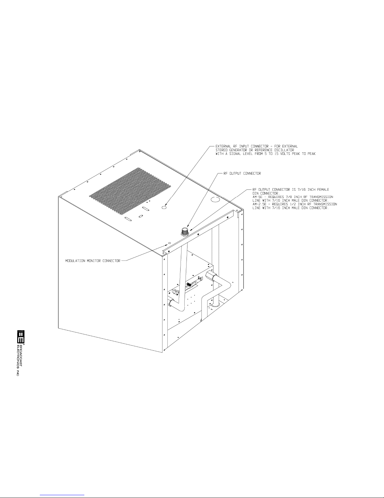
must be practiced to prevent accidents.
In addition to high voltages and currents, the AM transmitters contain multiple circuit grounds with
high ac and dc potentials with respect to the cabinet which is at earth potential. The potentials could
cause serious injury or death if maintenance personnel simultaneously touch a circuit ground and the
cabinet. As a result, operation of the transmitter with test equipment connected to transmitter output
network, RF power module, RF combiner, or power supply components is extremely dangerous and must
not be attempted. Therefore, never energize the transmitter with test equipment connected to the trans
mitter output network, RF power module, RF combiner, or power supply components. Test equipment
may be connected to the ECU circuit boards from the front of the transmitter using the supplied extender
circuit board with power energized if required.
THE TRANSMITTER CONTAINS MULTIPLE CIRCUIT
GROUNDS WITH HIGH AC AND DC POTENTIALS WITH
RESPECT TO THE CABINET WHICH IS AT EARTH PO
TENTIAL. DO NOT ENERGIZE THE TRANSMITTER
WITH TEST EQUIPMENT CONNECTED TO THE
TRANSMITTER OUTPUT NETWORK, RF POWER MOD
ULE, RF COMBINER, OR POWER SUPPLY COMPO
NENTS.
Page 5

SCOPE OF MANUAL
This manual consists of two sections which provides the following information for the Broadcast
Electronics AM-2.5E and AM-5E AM Broadcast Transmitters.
A. PART I - Contains information relative to installation, operation, and
maintenance applicable to the overall transmitter.
B. PART II - Contains detailed information for the following transmitter
modular units.
1. POWER SUPPLY ASSEMBLY
2. RF POWER MODULE
3. OUTPUT NETWORK
4. EXCITER/CONTROLLER UNIT (ECU)
PART I - TABLE OF CONTENTS
PARAGRAPH PAGE NO.
SECTION I GENERAL INFORMATION
1-1 INTRODUCTION 1-1
1-3 EQUIPMENT DESCRIPTION 1-1
1-4 GENERAL 1-1
1-6 EXCITER/CONTROL UNIT 1-1
1-12 OUTPUT NETWORK ASSEMBLY 1-4
1-13 RF POWER MODULE 1-4
1-15 POWER SUPPLY 1-4
1-16 COMBINER ASSEMBLY 1-4
1-17 TRANSMITTER CONFIGURATIONS 1-5
1-19 ACCESSORIES AND SPARE PARTS KITS 1-5
1-21 EQUIPMENT SPECIFICATIONS 1-5
SECTION II INSTALLATION
2-1 INTRODUCTION 2-1
2-3 UNPACKING 2-1
2-6 ENVIRONMENTAL REQUIREMENTS 2-1
2-8 COOLING AIR REQUIREMENTS 2-1
2-12 PRIMARY POWER 2-1
2-14 INSTALLATION 2-1
2-16 EQUIPMENT PLACEMENT 2-2
2-19 COMPONENT INSTALLATION 2-2
2-22 ECU CIRCUIT BOARDS 2-2
2-23 RF POWER MODULES 2-2
2-24 POWER SUPPLY 2-7
2-25 BATTERY INSTALLATION 2-8
2-26 CIRCUIT BOARD PROGRAMMING 2-8
2-28 EXCITER CIRCUIT BOARD 2-8
2-37 STEREO CIRCUIT BOARD 2-12
2-42 CONTROLLER CIRCUIT BOARD 2-12
Broadcast Electronics 1999
ALL RIGHTS RESERVED
Printed in the U.S.A.
-i -
Page 6

PARAGRAPH PAGE NO.
2-55 POWER SUPPLY CIRCUIT BOARD 2-15
2-58 REMOTE CONTROL 2-16
2-59 GENERAL 2-16
2-84 WIRING 2-20
2-86 AUDIO INPUT CONNECTION 2-20
2-88 EXTERNAL STEREO RF INPUT 2-20
2-89 AM-2.5E/AM-5E RF TRANSMISSION 2-20
LINE CONNECTION
2-90 EXTERNAL INTERLOCK 2-20
2-91 MODULATION MONITOR 2-20
2-92 AC POWER CONNECTIONS 2-22
2-95 GROUND 2-22
2-96 TRANSMITTER SITE LIGHTNING PROTECTION 2-22
SYSTEM CHECKOUT
2-98 ANTENNA BALL-GAP LIGHTNING ARRESTOR 2-25
2-102 ANTENNA-TUNING-UNIT SPARK-GAP 2-25
LIGHTNING ARRESTOR
2-103 TRANSMITTER SITE GROUNDING SYSTEM 2-25
2-104 CABLE PROTECTION 2-26
2-110 ANTENNA RF FEED LINE 2-26
2-111 TRANSMISSION LINE AND ANTENNA CHECKOUT 2-26
2-113 ANTENNA VSWR 2-26
2-114 COAXIAL SWITCH CONTROLLER 2-26
2-115 ATU AND PHASOR CHECKOUT 2-28
2-116 INITIAL CHECKOUT 2-28
2-118 PRELIMINARY OPERATION AND ADJUSTMENT 2-28
2-120 TUNING 2-28
2-126 POWER LEVEL AND MODULATION MONITOR 2-29
CALIBRATION ADJUSTMENTS
2-138 STEREO ADJUSTMENT 2-30
2-149 SINGLE CHANNEL LEVEL 2-32
SECTION III OPERATION
3-1 INTRODUCTION 3-1
3-3 CONTROLS AND INDICATORS 3-1
3-5 OPERATION 3-12
3-6 TURN-ON 3-12
3-14 TURN OFF 3-13
3-16 METERING 3-13
3-17 FORWARD POWER 3-13
3-18 REFLECTED POWER 3-13
3-19 POWER ADJUST 3-13
3-21 MONO/STEREO OPERATION 3-14
3-23 STEREO OPERATION 3-14
3-24 MONO OPERATION 3-14
3-27 PILOT CONTROL 3-14
3-29 EXCITER MONITOR OPERATION 3-14
3-31 MONO/STEREO INDICATIONS 3-14
3-32 INPUT SELECTION 3-14
3-33 POLARITY SELECTION 3-15
3-34 X10 AUTORANGE INDICATIONS 3-15
-ii -
Page 7

PARAGRAPH PAGE NO.
3-35 FAULT RESET 3-15
3-37 POWER SUPPLY FAULT RESET 3-15
3-39 OVER-CYCLE OFF 3-15
3-41 OVER-MODULATION PWM MUTE 3-15
3-43 TRANSMITTER MONITOR 3-15
3-45 BATTERY TEST 3-15
3-47 CONTROLLER PWM MUTE INDICATOR 3-16
3-49 CONTROLLER REMOTE FAIL-SAFE INDICATOR 3-16
3-51 EXCITER LOCK INDICATOR 3-16
3-53 EXCITER +5V/+15V/-15V INDICATORS 3-16
3-55 STEREO EQUALIZATION INDICATORS 3-16
3-57 RF POWER MODULE INDICATORS 3-16
3-59 POWER SUPPLY INDICATORS 3-16
3-61 EXCITER NEGATIVE LIMITER INDICATOR 3-16
3-63 HIGH/LOW AC LINE CONDITIONS 3-16
SECTION IV THEORY OF OPERATION
4-1 INTRODUCTION 4-1
4-5 FUNCTIONAL DESCRIPTION 4-1
4-6 ECU 4-1
4-7 GENERAL 4-1
4-8 STEREO CIRCUIT BOARD 4-1
4-11 EXCITER CIRCUIT BOARD 4-1
4-13 CONTROLLER CIRCUIT BOARD 4-2
4-18 POWER SUPPLY 4-2
4-19 RF POWER MODULE 4-2
4-24 RF COMBINER 4-7
4-27 OUTPUT NETWORK 4-7
4-31 POWER SUPPLY 4-8
4-34 POWER SUPPLY CIRCUIT BOARD 4-8
4-39 METERING 4-9
4-42 COOLING FANS 4-9
4-44 INTERFACE CIRCUIT BOARD (AM-5E ONLY) 4-9
4-46 DETAILED DESCRIPTION 4-9
4-47 POWER SUPPLIES 4-9
4-49 AC INPUT CIRCUITRY 4-9
4-53 ECU POWER SUPPLY ASSEMBLY 4-10
4-57 TRANSMITTER FLUSHING FANS 4-10
4-60 LOW-VOLTAGE POWER SUPPLY TRANSFORMER 4-10
4-62 POWER SUPPLY CIRCUIT BOARD 4-10
4-65 CONVENTIONAL RECTIFIER CIRCUITRY 4-13
4-68 SWITCHING POWER SUPPLY CIRCUIT 4-13
4-76 MODULATOR CIRCUIT BOARD 4-14
4-81 POWER AMPLIFIER CIRCUIT BOARDS 4-15
4-86 SEQUENCE OF OPERATION 4-15
4-91 RF CIRCUITRY 4-16
4-92 EXCITER CIRCUIT BOARD 4-16
4-98 STEREO CIRCUIT BOARD 4-17
4-102 RF POWER MODULE 4-17
4-109 RF COMBINER 4-21
4-110 HARMONIC BAND-PASS FILTER 4-22
-iii-
Page 8

PARAGRAPH PAGE NO.
4-111 DIRECTIONAL COUPLER CIRCUIT BOARD 4-22
4-115 T-MATCHING NETWORK 4-22
4-116 LIGHTNING PROTECTION CIRCUIT BOARD 4-22
4-117 LIGHTNING DETECTION CIRCUIT BOARD 4-23
4-119 RF OUTPUT POWER CONTROL CIRCUITRY 4-23
SECTION V MAINTENANCE
5-1 INTRODUCTION 5-1
5-3 SAFETY CONSIDERATIONS 5-1
5-6 FIRST LEVEL MAINTENANCE 5-1
5-8 ROUTINE MAINTENANCE 5-1
5-9 INSPECTION AND CLEANING 5-2
5-10 CONTROLLER BATTERY 5-2
5-11 AIR FILTERS 5-2
5-12 FLUSHING FANS 5-2
5-14 SPARK GAP 5-2
5-15 SECOND LEVEL MAINTENANCE 5-2
5-18 ELECTRICAL ADJUSTMENTS 5-4
5-20 TRANSMITTER FREQUENCY RE-PROGRAMMING 5-4
5-22 TROUBLESHOOTING 5-4
5-24 TRANSMITTER INDICATORS 5-5
5-25 RF POWER MODULE REMOVAL 5-8
5-26 TRANSMITTER TROUBLESHOOTING 5-8
PROCEDURES
5-27 TRANSMITTER COMPONENT LOCATIONS 5-8
5-28 COMPONENT REPLACEMENT PROCEDURE 5-13
5-34 INTEGRATED CIRCUITS 5-14
SECTION VI PARTS LIST
6-1 INTRODUCTION 6-1
SECTION VII DRAWINGS
7-1 INTRODUCTION 7-1
LIST OF TABLES
TABLE DESCRIPTION PAGE NO.
1-1 ELECTRICAL CHARACTERISTICS 1-5
1-2 PHYSICAL AND ENVIRONMENTAL 1-9
CHARACTERISTICS
3-1 AM-2.5E/AM-5E CONTROLS AND INDICATORS 3-1
3-2 ECU CONTROLS AND INDICATORS 3-3
3-3 POWER MODULE CONTROLS AND INDICATORS 3-11
5-1 AM-2.5E/AM-5E INDICATORS 5-5
5-2 AM-2.5E/AM-5E TROUBLESHOOTING 5-9
6-1 AM-2.5E/AM-5E REPLACEABLE PARTS LIST INDEX 6-1
-iv-
Page 9

LIST OF ILLUSTRATIONS
FIGURE DESCRIPTION PAGE NO.
1-1 AM-2.5E TRANSMITTER 1-2
1-2 AM-5E TRANSMITTER 1-3
2-1 AM-2.5E TRANSMITTER INSTALLATION 2-3
2-2 AM-5E TRANSMITTER INSTALLATION 2-5
2-3 TRANSMITTER MOVING 2-7
2-4 COMPONENT INSTALLATION 2-9
2-5 EXCITER CIRCUIT BOARD PROGRAMMING 2-11
2-6 STEREO CIRCUIT BOARD PROGRAMMING 2-13
2-7 CONTROLLER CIRCUIT BOARD PROGRAMMING 2-14
2-8 REMOTE CONTROL AND AUDIO CONNECTIONS 2-17
2-9 AM-2.5E/AM-5E RF OUTPUT CONNECTIONS 2-21
2-10 AM-2.5E PRIMARY AC WIRING 2-23
2-11 AM-5E PRIMARY AC WIRING 2-24
2-12 ANTENNA LIGHTNING PROTECTION SYSTEM 2-27
2-13 TEST EQUIPMENT CONNECTIONS, POWER LEVEL 2-30
CALIBRATION
2-14 TEST EQUIPMENT CONNECTIONS, SEPARATION 2-31
2-15 EQUALIZATION LISSAJOUS PATTERNS 2-33
3-1 AM-2.5E/AM-5E CONTROLS AND INDICATORS 3-2
3-2 ECU CONTROLS AND INDICATORS 3-7
3-3 POWER MODULE CONTROLS AND INDICATORS 3-11
4-1 AM-2.5E BLOCK DIAGRAM 4-3
4-2 AM-5E BLOCK DIAGRAM 4-5
4-3 AM-2.5E/AM-5E POWER SUPPLY SIMPLIFIED 4-11
SCHEMATIC
4-4 AM-2.5E/AM-5E RF CIRCUITRY SIMPLIFIED 4-18
SCHEMATIC
5-1 REMOVING THE AIR FILTER 5-3
5-2 AM-2.5E COMPONENT LOCATOR 5-15
5-3 AM-5E COMPONENT LOCATOR 5-18
5-4 AM-2.5E/AM-5E ECU/POWER BLOCK/OUTPUT 5-21
NETWORK ASSEMBLY COMPONENT LOCATOR
PART II - TABLE OF CONTENTS
I - POWER SUPPLY ASSEMBLY
II - RF POWER MODULE
III - OUTPUT NETWORK
IV - EXCITER/CONTROLLER UNIT (ECU)
-v -
Page 10

SECTION I
GENERAL INFORMATION
1-1. INTRODUCTION.
1-2. Information presented by this section provides a general description of the Broadcast
Electronics AM-2.5E and AM-5E transmitters and lists equipment specifications.
1-3. EQUIPMENT DESCRIPTION.
1-4. GENERAL.
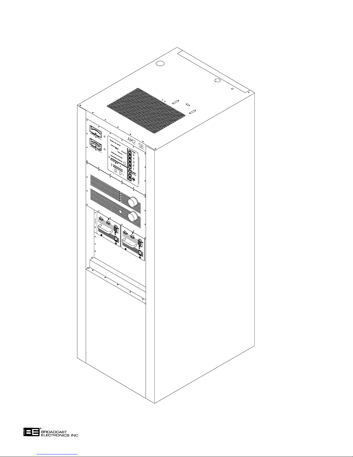
1-5. The Broadcast Electronics AM-2.5E transmitter is a CE compliant 2.5 kW solid-state
C-QUAM stereo AM transmitter designed for continuous operation in the 522 kHz to
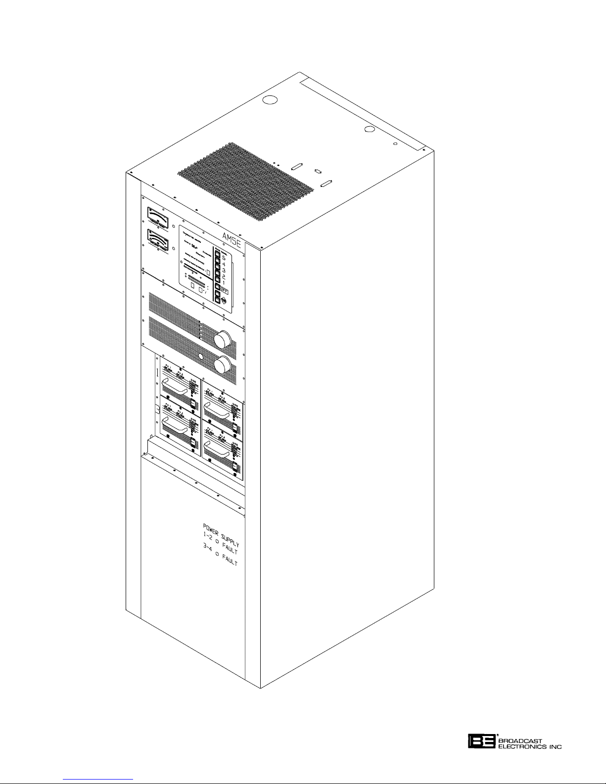
1705 kHz broadcast band (refer to Figure 1-1). The Broadcast Electronics AM-5E trans
mitter is a CE compliant 5 kW solid-state C-QUAM stereo AM transmitter designed for
continuous operation in the 522 kHz to 1705 kHz broadcast band (refer to Figure 1-2). The
AM-2.5E and AM-5E transmitters consists of modular components assembled in a single
cabinet. The modular components include: 1) an exciter/control unit, 2) an output network
assembly, 3) power block assemblies containing two RF power modules and a star combiner
assembly, 4) power supply panel assemblies, and 5) an AC distribution panel assembly.
Specific AM-2.5E/AM-5E features include:
1. Built-in C-QUAM AM stereo circuitry.
2. High efficiency Class E solid-state RF power amplifier modules.
3. A high efficiency switching power supply.
4. Star combiner assembly. Each star combiner allows the removal of RF power modules without the use of dummy modules or bypass switches.
5. A built-in output matching network.
6. A CMOS digital controller with extensive VSWR detection and foldback circuitry
which reduces carrier interruptions by weather conditions.
7. CE compliant design.
1-6.
1-7. Stereo Circuit Board. The ECU stereo circuit board is a modular plug-in assembly con
1-8. The stereo circuit board is designed with remote/local controlled mono left, mono right,
EXCITER/CONTROL UNIT. The transmitter exciter/control unit (ECU) is a modular as
sembly containing plug-in stereo, exciter, and controller circuit boards. In addition to the
circuit boards, the ECU is equipped with forward and reflected power meters to provide
transmitter output power status indications.
taining C-QUAM AM stereo circuitry. The C-QUAM stereo system is a mode of AM
stereo transmission utilizing amplitude modulated monaural (L+R) information and inde
pendently quadrature modulated stereo (L-R) information. The results produce a stereo
transmission system compatible with mono receivers.
mono L+R, and stereo modes of operation. Two equalization circuits are provided to allow
the transmitter to be configured for operation into two different antennas.
C-QUAM is a registered trademark of Motorola Inc.
1-1
Page 11
COPYRIGHT 1999 BROADCAST ELECTRONICS, INC
FIGURE 1-1. AM-2.5E TRANSMITTER
597-1114-1
1-2
Page 12
COPYRIGHT 1999 BROADCAST ELECTRONICS, INC
FIGURE 1-2. AM-5E TRANSMITTER
1-3
597-1114-2
Page 13

1-9. Exciter Circuit Board. The ECU exciter circuit board is a modular plug-in exciter assem
bly. Instrumentation amplifiers provide balanced left and right channel transformerless
audio inputs. The exciter carrier frequency is established by a digital frequency synthesiz
er. The synthesizer is a phase-locked-loop circuit which provides extremely accurate and
reliable carrier frequency operation. A PWM (pulse-width-modulation) circuit is used to
generate an RF drive signal for application to a modulator circuit board in an RF power
module. If a stereo circuit board failure is encountered or when the stereo circuit board is
removed from the ECU chassis, the exciter circuitry is designed to automatically configure
to monophonic operation.
1-10. Controller Circuit Board. All transmitter control operations are directed by the ECU con
troller circuit board. The controller circuit board consists of CMOS logic control and moni
toring circuitry. The circuitry is designed to interface to all popular remote control systems
such as the Broadcast Electronics VMC-16 remote control system.
1-11. The transmitter power is controlled by a power control circuit. The circuit allows the
transmitter to be operated at five power levels. A power trim circuit allows the transmitter
output power to be adjusted to a precise level. An antenna interlock circuit is provided to
prevent the transmitter from operating into an incorrect antenna. A reflected power detec
tion circuit operates in association with the power control circuit to foldback the transmit
ter power during high VSWR conditions. In addition to the reflected power detector, a
lightning detector circuit is provided to mute the transmitter when high voltage is present
at the transmitter output during a lightning storm.
1-12.
1-13.
1-14. The RF power modules are designed using Class E amplifier technology. A Class E ampli
1-15.
OUTPUT NETWORK ASSEMBLY. Matching of the transmitter impedance to the antenna is
accomplished by the output network assembly. The assembly is equipped with an
LC T network to match the transmitter output to the antenna. A bandpass filter is pro
vided to attenuate all harmonic frequencies to FCC, DOC, and CCIR levels. The assembly
also contains the lightning detection circuit board, a lightning protection circuit board, and
a directional coupler assembly.
RF POWER MODULE. The AM-2.5E and AM-5E transmitters are equipped with RF pow
er modules. A power module is a modular plug-in assembly containing two RF power am
plifier circuit boards and one modulator circuit board. Each power module is equipped
with MOSFET transistors to produce approximately 1375 watts of RF power.
fier exhibits high efficiency and provides superior audio performance. In addition to the
superior efficiency and audio performance, the power modules are designed to be removed
from the chassis for maintenance. The remaining power modules will provide full power to
maintain on-air operation.
POWER SUPPLY. A modular switching power supply provides operating potentials for two
RF power modules. The power supply design uses an SCR controlled bridge to rectify the
ac line voltage into a dc potential. The supply is filtered and routed to the RF power mod
ules for control and regulation. A fault detection circuit monitors power supply activity for
failure conditions. A separate modular switching power supply provides operating poten
tials for the ECU circuitry.
1-16.
COMBINER ASSEMBLY. The AM-2.5E and AM-5E are equipped with a star combining
system. The system combines the outputs of the RF power modules to provide: 1) a 2.5
kW output in AM-2.5E models and 2) a 5 kW output in AM-5E models. If a power module
is removed from the chassis, the remaining power modules will continue operation to main
tain on-air operation.
1-4
Page 14

1-17. TRANSMITTER CONFIGURATIONS.
1-18. The AM-2.5E and AM-5E transmitters can be ordered in the following configurations:
P/N DESCRIPTION
907-2500-100 AM-2.5E 2.5 kW AM Transmitter for operation in
the 522 kHz to 1705 kHz broadcast band, 10 kHz
spacing, 196V - 256V ac single phase supply.
907-5000-100 AM-5E 5 kW AM Transmitter for operation in
the 522 kHz to 1705 kHz broadcast band, 10 kHz
spacing, 196V - 256V ac single phase supply.
1-19.
ACCESSORIES AND SPARE PARTS KITS.
1-20. The following text presents accessories and spare parts kits available for use with the
AM-2.5E and AM-5E transmitters.
P/N DESCRIPTION
977-0038 AM-2.5E/AM-5E recommended semi-conductor
kit.
977-0039 AM-2.5E 100% semi-conductor kit.
977-0040 AM-2.5E/AM-5E recommended spare parts kit.
Includes selected meters, switches, fuses, filters,
etc. Does not include semi-conductors.
977-0041 AM-5E 100% semi-conductor kit.
907-0016-110 VMC-16 Voice Remote Control Unit, AM-10A/
AM-6A/AM-2.5E/AM-5E.
977-0037 Basic semi-conductor kit, AM-10A/AM-6A/
AM-1A/AM-2.5E/AM-5E.
1-21. EQUIPMENT SPECIFICATIONS.
1-22. Refer to Table 1-1 for electrical specifications or Table 1-2 for physical specifications of the
AM-2.5E and AM-5E transmitters.
TABLE 1-1. ELECTRICAL CHARACTERISTICS
(Sheet 1 of 5)
PARAMETER SPECIFICATION
RF POWER OUTPUT
AM-2.5E 12.5 W to 2.8 kW. Five preset power levels
AM-5E 25 W to 5.6 kW. Five preset power levels
available by local or remote control. Will operate
at a reduced power output (30-50% typical) with
one-half of the power modules.
available by local or remote control. Will operate
at a reduced power output (30-50% typical) with
one-half of the power modules.
1-5
Page 15

TABLE 1-1. ELECTRICAL CHARACTERISTICS
(Sheet 2 of 5)
PARAMETER SPECIFICATION
OUTPUT POWER REGULATION Less than 1% change in output power with vari-
ation of ac line input voltage from 196V to 252V
ac.
RF CARRIER FREQUENCY 522 kHz to 1705 kHz (as ordered).
RANGE Accommodates 9 kHz or 10 kHz channel spacing
(9 kHz spacing requires an optional crystal).
RF OUTPUT IMPEDANCE 50 Ohms, unbalanced. Matching network to
optimize VSWR of 1.5 : 1 at any phase angle and
carrier frequency.
OUTPUT CONNECTOR Female 7/16 DIN connector.
AM-5E Requires 7/8 inch RF transmission line with 7/16
male DIN connector.
AM-2.5E Requires 1/2 inch RF transmission line with 7/16
male DIN connector.
LOAD VSWR 1.5 : 1 at full carrier power. Will operate into a
higher VSWR with automatic power reduction.
Open and short circuit protected.
HARMONIC AND SPURIOUS Meets or exceeds FCC, DOC, and CCIR requireSUPPRESSION ments when preceded by external NRSC-1 com-
patible audio low-pass filters.
CARRIER FREQUENCY ±3ppm, 0° to 50° C (+32° to +122° F).
STABILITY
CARRIER SHIFT Less than 1% at 95% negative modulation at
1 kHz.
TYPE OF MODULATION Pulse Width Modulation of L+R envelope with
integrated C-QUAM AM stereo. An RF input
connector is also provided for an external stereo
exciter.
OPERATING MODES Stereo, mono L+R, mono L, mono R, by local or
remote control.
MODULATION CAPABILITY
AM-2.5E Greater than 145% peak positive capability at
2.5 kW.
AM-5E Greater than 145% peak positive capability at
5 kW.
MODULATION INPUT INDICATION Peak reading, color coded, LED bar graph display
with an autorange feature for monitoring positive
or negative input levels of four different audio
channels (L/R or L+R/L-R).
AUDIO INPUT LEVEL +10 dBm, ±1 dB, L=R (or mono) to produce 100%
L+R envelope modulation. Other input levels can
be accommodated.
1-6
Page 16

TABLE 1-1. ELECTRICAL CHARACTERISTICS
(Sheet 3 of 5)
PARAMETER SPECIFICATION
AUDIO INPUT IMPEDANCE 600 Ohms. Inputs are balanced, transformerless,
and resistive with passive RFI filtering. Other
impedances can be accommodated.
AUDIO FREQUENCY ±0.5 dB, 20 Hz to 10 kHz at 90% negative
RESPONSE (MONOPHONIC) modulation (linear phase mode). +0.1 dB
-3 dB, 20 Hz to 10 kHz at 90% negative
modulation, standard configuration.
AUDIO HARMONIC DISTORTION
Mono Less than 0.8%, 20 Hz to 10 kHz at rated power.
Less than 1.5%, 20 Hz to 10 kHz at 50% power.
Less than 2.0%, 20 Hz to 10 kHz at 25% power.
Less than 3.0%, 20 Hz to 10 kHz at 10% power.
All mono audio harmonic distortion specifications
are referenced to an audio input level which
generates 90% modulation at 1 kHz (9 dBm).
Stereo Less than 1.5% at 50% single channel
modulation, 50 Hz to 10 kHz at rated power.
INTERMODULATION DISTORTION 1.2% or less at 1:1 ratio. 1.7% or less at 4:1 ratio.
(MONO) 60/7000 Hz SMPTE standards with 85%
modulation at rated power.
CCIF INTERMODULATION 1.0% or less at 1:1 ratio. 4 kHz/5 kHz with 85%
DISTORTION (MONO) modulation at rated power.
TRANSIENT INTERMODULATION 1.0% or less at 4:1 ratio. 2.96 kHz square wave
DISTORTION (MONO) 8 kHz sinewave with 85% modulation at rated
power.
INCIDENTAL PHASE Less than 2.0 degrees (0.035 radians) average or 30
MODULATION dB (40 dB typical) below equivalent 100% L-R
(STEREOPHONIC) C-QUAM modulation, 50 Hz to 10 kHz at rated
power. Measured with an audio input level which
generates 95% negative L+R envelope modulation
at 1 kHz (9.5 dBm).
STEREO SEPARATION -30 dB or greater, 50 Hz to 10 kHz. Measured
with 50% single channel modulation into a 50 ohm
resistive load at rated power.
SQUAREWAVE OVERSHOOT
Mono 0.1% or less at 400 Hz, 90% modulation with high
frequency boost disabled.
Stereo 1.0% or less at 400 Hz, 50% single channel modu-
lation with high frequency boost disabled.
1-7
Page 17

TABLE 1-1. ELECTRICAL CHARACTERISTICS
(Sheet 4 of 5)
PARAMETER SPECIFICATION
SQUAREWAVE TILT 1.0% or less at 40 Hz. 1.5% or less at 20 Hz.
Measured with 90% negative modulation.
NOISE
Mono Greater than 65 dB below a reference level
equivalent to 100% negative modulation in a 22
Hz to 30 kHz bandwidth, unweighted.
Stereo Greater than 55 dB below a reference level
equivalent to 100% negative modulation of
either left or right channel in a 22 Hz to
30 kHz bandwidth, unweighted.
AC INPUT VOLTAGE 196V to 252V ac 50/60 Hz, single phase.
Includes built-in MOVs for surge suppression.
AC POWER CONSUMPTION
AM-2.5E 3.3 kW, no modulation of 2.5 kW carrier.
2.05 kW, 100% modulation of 2.5 kW carrier.
Measured at 2.5 kW into a 50 ohm resistive
load at 220V ac. 0.9 power factor.
AM-5E 6.7 kW, no modulation of 5 kW carrier.
10 kW, 100% modulation of 5 kW carrier.
Measured at 5 kW into a 50 ohm resistive
load at 220V ac. 0.9 power factor.
OVERALL EFFICIENCY
AM-2.5E 75% or greater, 100% sinusoidal modulation
of carrier, ac line to RF output. Measured
at into 2.5 kW a 50 ohm resistive load at
220V ac.
AM-5E 75% or greater, 100% sinusoidal modulation of
carrier, ac line to RF output. Measured at 5 kW
into a 50 ohm resistive load at 220V ac.
SAFETY Meets IEC 215 specifications.
REGULATORY Meets CE specifications.
METERING
AM-2.5E Output Forward Power: 1) High scale - 0 to
3000 watts and 2) Low scale - 0 to 750 watts.
Output Reflected Power: 1) High scale - 0 to 300
watts and 2) Low scale - 0 to 60 watts. Ac Line
Voltage: Scale - 150 to 300 volts. AM-2.5
Forward Power Meter complies with FCC rule
78.1215 (a) within the 150 watt to 2800 watt range.
1-8
Page 18

TABLE 1-1. ELECTRICAL CHARACTERISTICS
(Sheet 5 of 5)
PARAMETER SPECIFICATION
METERING (CONT'D)
AM-5E Output Forward Power: 1) High scale - 0 to 6000
watts and 2) Low scale - 0 to 1500 watts.
Output Reflected Power: 1) High scale - 0 to
600 watts and 2) Low scale - 0 to 150 watts. Ac
Line Voltage: Scale - 150 to 300 volts. AM-5
Forward Power Meter complies with FCC rule
73.1215 (a) within the 300 watt to 5600 watt
range.
RF MONITORING PROVISIONS 2 volts RMS nominal RF output sample into a 50
Ohm input. Adjustable from the transmitter
front panel for each of the five power levels.
REMOTE INTERFACE Built-in interface for most control and monitoring
systems.
TABLE 1-2. PHYSICAL AND ENVIRONMENTAL CHARACTERISTICS
(Sheet 1 of 2)
PARAMETER SPECIFICATION
PHYSICAL
DIMENSIONS Width: 24.82 Inches (63.0 cm).
Height: 71.32 Inches (181.2 cm)
Depth: 31.55 Inches (80.1 cm)
WEIGHT
AM-2.5E 410 Pounds (186 kg), unpacked.
AM-5E 525 Pounds (238 kg), unpacked.
3
(1.2 m3).
CUBAGE 42.8Ft
ENVIRONMENTAL
COOLING
Type Low velocity air with disposable filters.
Requirements - AM2.5E/AM-5E 500 Cubic Feet Per Minute (14.15 m
OPERATING TEMPERATURE 0° to 50° C (+32° to +122° F)
OPERATING HUMIDITY 0 TO 95% (non-condensing)
3
/min).
1-9
Page 19

TABLE 1-2. PHYSICAL AND ENVIRONMENTAL CHARACTERISTICS
(Sheet 2 of 2)
PARAMETER SPECIFICATION
MAXIMUM ALTITUDE
60 Hz Models 0 to 10,000 feet above sea level (0 to 3048 Meters).
50 Hz Models 0 to 7,500 feet above sea level (0 to 2286 Meters).
NOTE -
For AM-2.5E, All specifications measured at 2.5 kW into a 50 ohm resistive load using
Broadcast Electronics AS-10 modulation monitor.
For AM-5E, All specifications measured at 5 kW into a 50 ohm resistive load using
Broadcast Electronics AS-10 modulation monitor.
1-10
Page 20

SECTION II
INSTALLATION
2-1. INTRODUCTION.
2-2. This section contains information required for the installation and preliminary checkout of
the Broadcast Electronics AM-2.5E and AM-5E transmitters.
2-3. UNPACKING.
2-4. The equipment becomes the property of the customer when the equipment is delivered to
the carrier. Carefully unpack the transmitter. Perform a visual inspection to determine
that no apparent damage has been incurred during shipment. All shipping materials
should be retained until it is determined that the unit has not been damaged. Claims for
damaged equipment must be promptly filed with the carrier or the carrier may not accept
the claim.
2-5. The contents of the shipment should be as indicated on the packing list. If the contents are
incomplete, or if the unit is damaged electrically or mechanically, notify both the carrier
and Broadcast Electronics.
2-6.
2-7. Table 1-2 provides environmental conditions which must be considered prior to transmit
2-8.
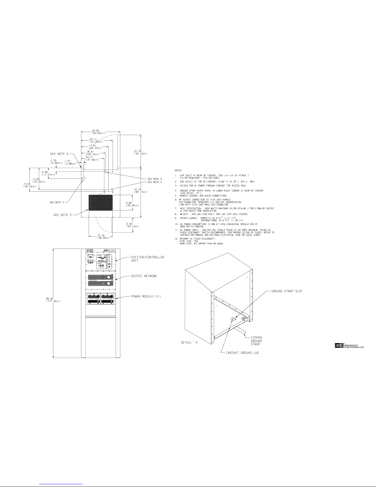
2-9. If outside air is to be used to cool the transmitter, the air inlet duct must be sized to allow
2-10. If the heated transmitter air is to be ducted from the room, the duct system must not
2-11. As a minimum requirement, any duct work must have a cross-sectional area equal to the
2-12.
2-13. The AM-2.5E and AM-5E transmitters are designed for operation from a 196V to 252V ac
ENVIRONMENTAL REQUIREMENTS.
ter installation. Refer to Table 1-2 in SECTION I, INTRODUCTION and ensure the
transmitter is to be installed in an acceptable environment.
COOLING AIR REQUIREMENTS.
adequate air flow. The air must be dry and well filtered. If intake louvers are used, opera
tion of the louvers must be electrically interlocked with the transmitter operation.
introduce any back-pressure on the equipment. Proper allowances for air flow will ensure
that only a limited amount of heat is dissipated into the equipment interior. The duct sys
tem must allow for a minimum air flow of: 1) 500 cubic feet of air per minute for AM-2.5E
models and 2) 700 cubic feet of air per minute for AM-5E models.
exhaust area of the cabinet (refer to Figure 2-1 and 2-2). Sharp bends in the duct system
will introduce back pressure and are not permissible. A radius bend must be used if a
right angle turn is required. An exhaust fan may be used to overcome duct losses or over
come wind pressures if the duct is vented to the outside.
PRIMARY POWER.
50/60 Hz single phase power source. Consult the local electric utility company to ensure
that the correct service is provided before connection of the transmitter to the primary
power source.
2-14. INSTALLATION.
2-15. Each transmitter is wired, operated, tested, and inspected at the factory prior to shipment
and is ready for installation when received. Prior to installation, this publication should be
studied to obtain an understanding of the operation, circuitry, nomenclature, and installa
tion requirements. Installation is accomplished as follows: 1) placement, 2) component
installation, 3) circuit board programming, 4) remote control connections, 5) wiring,
6) initial checkout, and 7) preliminary operation and tuning.
2-1
Page 21

2-16. EQUIPMENT PLACEMENT.
2-17. The transmitter is designed with access holes in the top of the cabinet to allow for the
over-head ducting of ac power, RF transmission line, and ground strap wiring (refer to
Figure 2-1/2-2). The floor must be capable of supporting the total transmitter weight of
approximately 90 pounds per square foot. The floor support should be more than marginal
to maintain proper cabinet alignment and reduce vibration.
2-18. Evaluate the installation site and determine the location of the transmitter. Once the
location is determined, refer to Figure 2-3 and use a forklift to move the transmitter to the
desired location. After the transmitter is placed in the desired location, remove the ship
ping skid as follows:
1. Refer to Figure 2-3 and remove the 5/16 inch shipping bolts securing the
transmitter to the skid.
2. Once the bolts are removed, slide the transmitter off the skid.
3. Slide the transmitter to the exact location.
2-19.
COMPONENT INSTALLATION.
WARNING
ENSURE NO PRIMARY POWER IS CONNECTED TO
THE TRANSMITTER BEFORE PROCEEDING.
WARNING
2-20. Selected components of the AM-2.5E and AM-5E transmitters have been removed to pre
vent damage during shipment. The components removed from the transmitter are shipped
in separate containers.
2-21. Remove all tape, wire ties, string, and packing material used for shipment. In addition,
locate the component containers. To install the components, perform the following proce
dures.
2-22.
ECU CIRCUIT BOARDS. The ECU circuit boards are removed for shipment. Locate the
circuit board shipping container. To re-install the circuit boards, proceed as follows:
CAUTION
THE TRANSMITTER MAY BE DAMAGED
IF THE ECU CIRCUIT BOARDS ARE NOT
CAUTION
1. Refer to Figure 2-4 to determine the circuit board location.
2. Insert the circuit board in the appropriate location.
3. Firmly press the circuit board into the connector.
SECURELY SEATED INTO THE CONNECTORS.
4. Firmly press the circuit board into the connector again to ensure the circuit board
is seated.
5. Repeat the procedure for each ECU circuit board.
CAUTION
REMOVING OR INSTALLING AN RF POWER MODULE
WITH THE TRANSMITTER ENERGIZED MAY RESULT
CAUTION
2-23. RF POWER MODULES. Each RF power module is removed for shipment. Locate the RF
power module shipping containers. Refer to Figure 2-4 and re-install the modules.
IN DAMAGE TO THE MODULE.
2-2
Page 22
597-1114-7
FIGURE 2-1. AM-2.5E TRANSMITTER INSTALLATION
(2-3/2-4)
COPYRIGHT 1999 BROADCAST ELECTRONICS, INC
Page 23
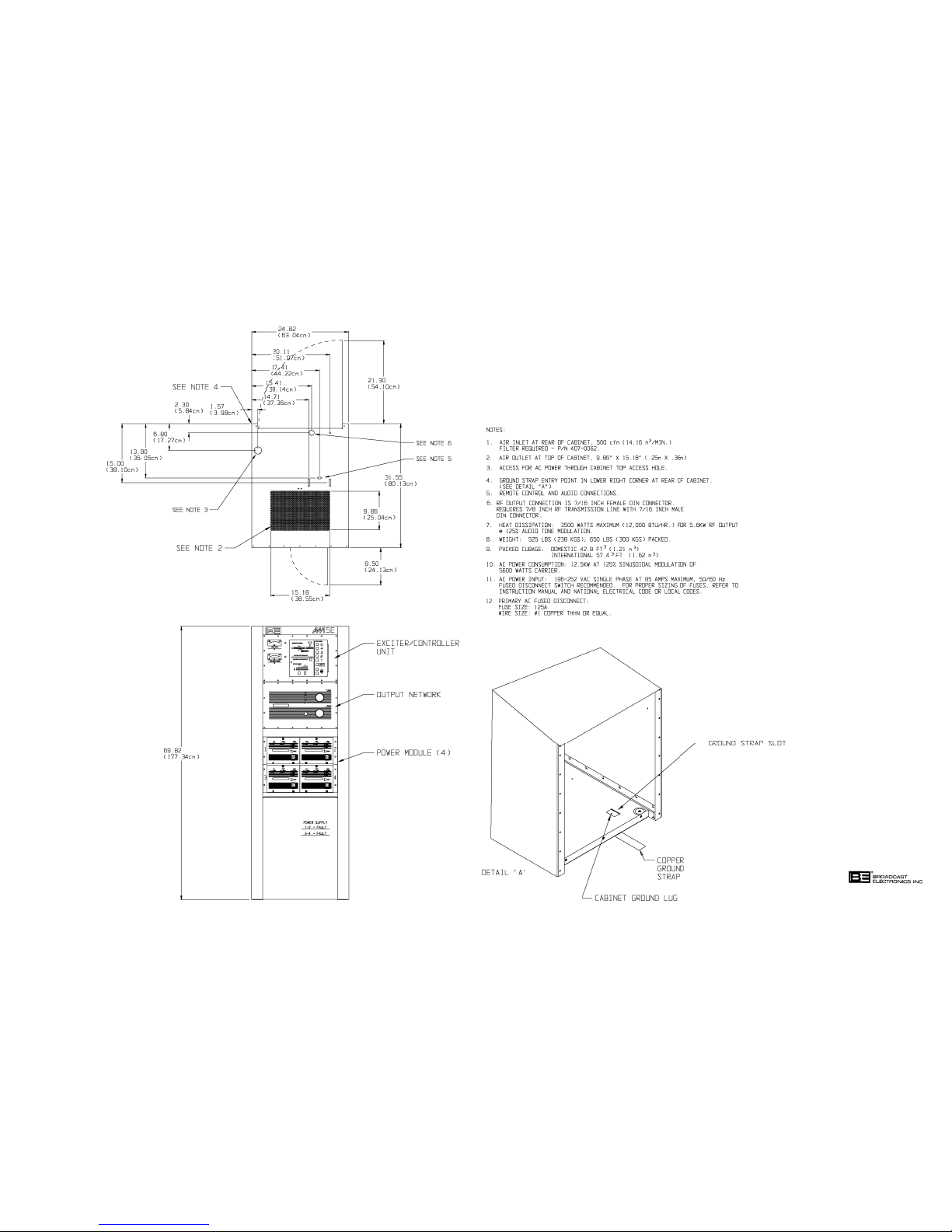
597-1114-8
FIGURE 2-2. AM-5E TRANSMITTER INSTALLATION
(2-5/2-6)
COPYRIGHT 1999 BROADCAST ELECTRONICS, INC
Page 24
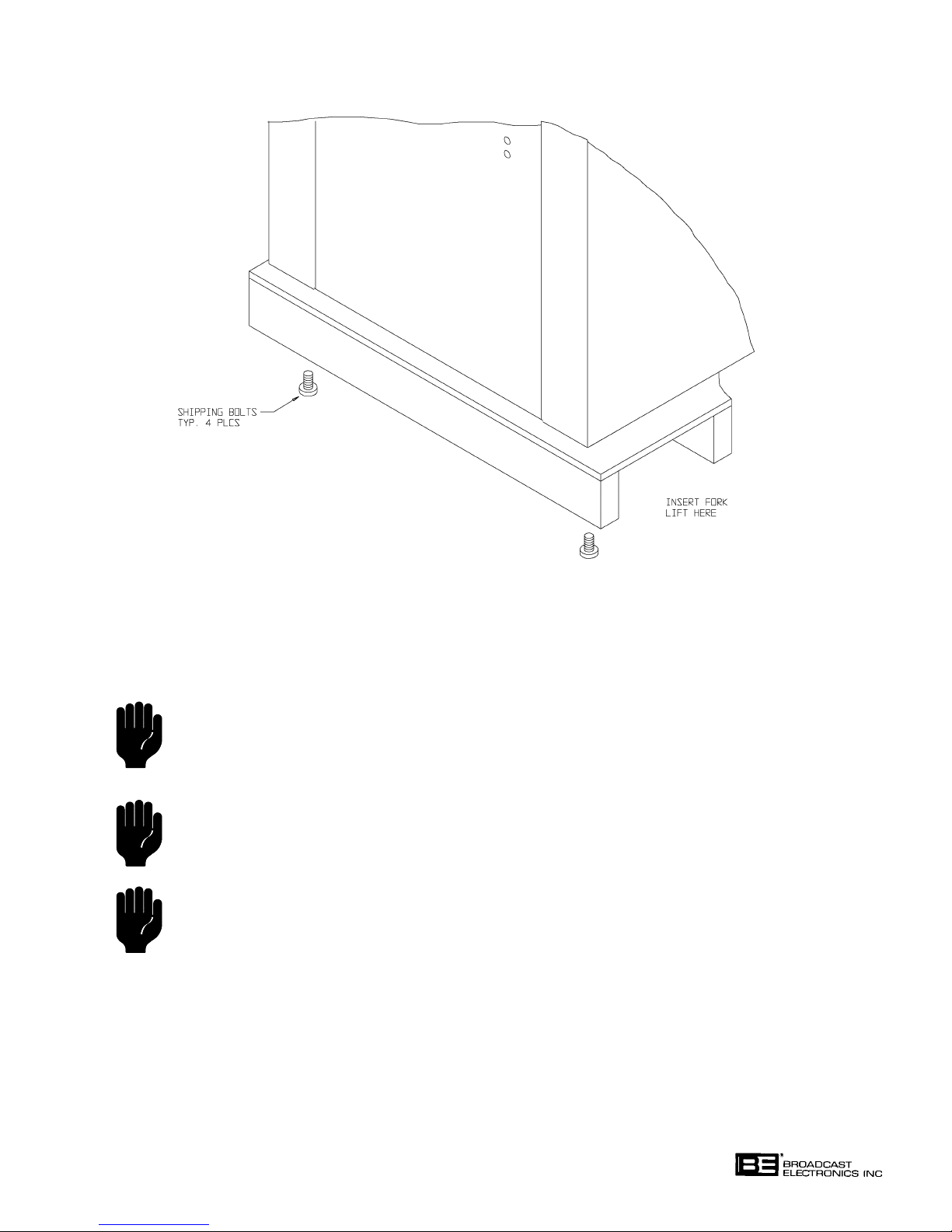
COPYRIGHT 1999 BROADCAST ELECTRONICS, INC
FIGURE 2-3. TRANSMITTER MOVING
2-24. POWER SUPPLY. The transmitter power supply circuit boards may be removed for ship
ment. If the power supply circuit boards have been removed, locate the shipping container.
Install each circuit board as follows:
597-1114-27
CAUTION
THE TRANSMITTER MAY BE DAMAGED IF THE
POWER SUPPLY CONNECTORS ARE NOT SE
CAUTION
CURELY SEATED INTO THE POWER SUPPLY
CIRCUIT BOARD RECEPTACLES.
CAUTION
TO PREVENT DAMAGE TO THE POWER SUP
PLY CIRCUIT BOARD, ENSURE THE CIRCUIT
CAUTION
BOARD IS INSERTED INTO THE MOUNTING
PINS AND THE CAPACITORS ON THE CIRCUIT
CAUTION
SIDE OF THE BOARD ARE PLACED INTO THE
PANEL CUTOUT PRIOR TO SLIDING THE CIR
CAUTION
CUIT BOARD TO SEAT THE MOUNTING SLOTS
INTO THE PINS.
1. Locate the mounting slots in the power supply circuit board and insert the board
into the power supply mounting pins on the power supply panel. Ensure the circuit
board is inserted with the capacitors on the circuit side of the board placed into the
panel cutout prior to seating the circuit board in the mounting pins.
2. Slide the circuit board in a position to seat the circuit board slots in the mounting
pins.
2-7
Page 25

3. Secure the power supply circuit board mounting hardware.
4. Connect the power supply circuit board cables as follows:
A. Securely connect 16-pin connector P1 to J1 on the power supply circuit board.
B. Securely connect 12-pin connector P2 to J2 on the power supply circuit board.
C. Securely connect 24-pin connector P3 to J3 on the power supply circuit board.
5. Repeat the procedure for each power supply circuit board.
2-25.
2-26. CIRCUIT BOARD PROGRAMMING.
2-27. The AM-2.5E and AM-5E transmitters are designed with programmable transmitter oper
2-28.
2-29. External Stereo Generator Select. Programmable header J7 programs the circuitry if:
2-30. Carrier Frequency Programming. Eight position switch S2 programs the exciter carrier
2-31. PWM Frequency Programming. Four position switch S1 programs the PWM frequency.
2-32. Frequency Synthesizer Programming. Programmable header J6 determines the frequency
2-33. Pilot Tone Programming. Programmable header J5 establishes the pilot tone frequency for
2-34. High-Pass Filter Defeat. Left channel programmable header J12 and right channel pro
2-35. High Frequency Boost Defeat. Left channel programmable header J2 and right channel
BATTERY INSTALLATION. The ECU is equipped with a battery system. Refer to Figure
2-4 and install the battery in the battery receptacle.
ating characteristics. The operating characteristics are determined by the programmable
circuitry on the ECU circuit boards (refer to Figure 2-4). Refer to the following text and
program the circuitry for the desired operating characteristics.
EXCITER CIRCUIT BOARD. Exciter circuit board programming is presented in Figure
2-5. Refer to Figure 2-5 and program the circuit board as required.
1) an external stereo generator is to be used with the transmitter or 2) the internal stereo
circuit board is to be used with the transmitter. The transmitter is shipped with the circuit
programmed for the internal stereo circuit board operation.
frequency. The switch is programmed for the station frequency at the factory. Refer to the
factory test data sheets to check the programming of the switch. If the switch program
ming is not identical to programming recorded in the factory test data sheets, contact the
Broadcast Electronics Customer Service Department.
Refer to the factory test data sheets to check the programming of the switch.
synthesizer band of operation. Refer to the factory test data sheets to check the program
ming of the header.
10 kHz carrier frequency operation and 9 kHz carrier frequency operation. Refer to the
factory test data sheets to check the programming of the header.
grammable header J13 control an exciter second order 10 Hz high-pass filter. The highpass filter is provided to remove low frequency residual products from specific audio pro
cessing units. The filter is shipped from the factory in the enabled position. Evaluate the
audio processor and determine if low frequency residual products are present at the output
of the audio processing unit. If no low frequency residual products are present, refer to
Figure 2-5 and disable the high pass filter.
programmable header J3 control an exciter high frequency boost circuit. The high frequen
cy boost circuit provides increased high frequency response to compensate for a Bessel fil
ter in the PWM modulator. If the high frequency boost circuit is enabled to compensate for
the filter, the circuit will result in a compromise between the frequency and transient re
sponse performance. If the high frequency boost circuit is enabled, the transmitter fre
quency response will increase approximately 2 dB at 10 kHz and the transient response
will degrade. If the high frequency boost circuit is disabled, the transmitter frequency re
sponse will decrease approximately 2 dB at 10 kHz and the transient response will im
prove. The high frequency boost circuit is shipped from the factory in the disabled posi
tion.
2-8
Page 26
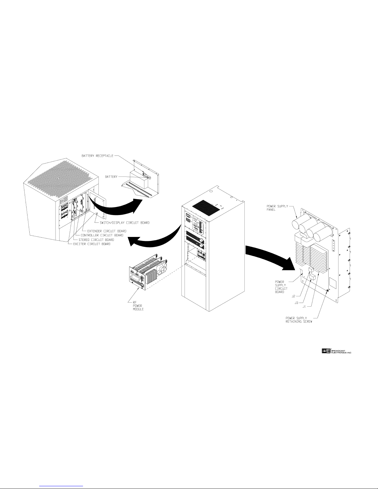
597-1114-14
FIGURE 2-5. COMPONENT INSTALLATION
(2-9/2-10)
COPYRIGHT 1999 BROADCAST ELECTRONICS, INC
Page 27
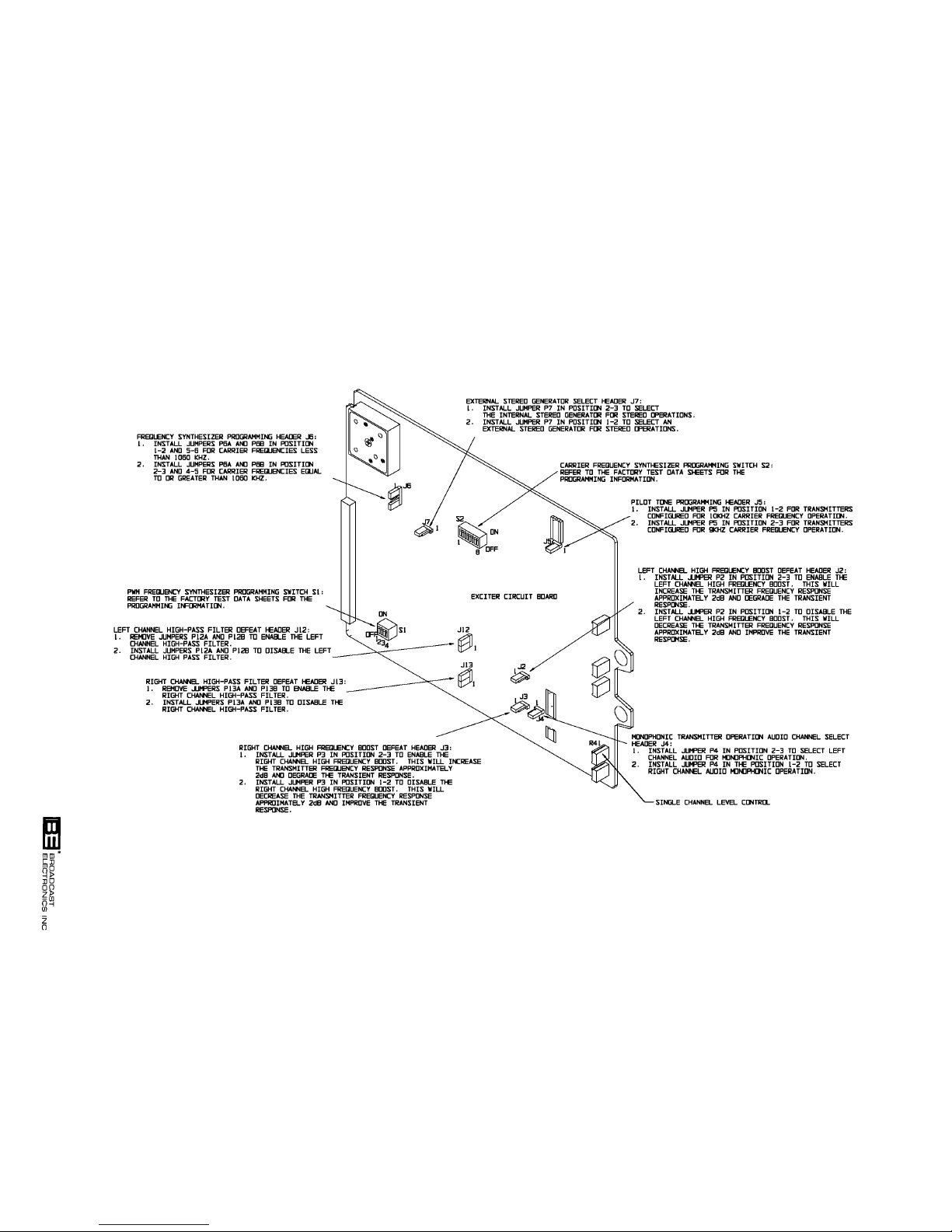
2-11
597-1111-11
FIGURE 2-5. EXCITER CIRCUIT BOARD PROGRAMMING
COPYRIGHT 1999 BROADCAST ELECTRONICS, INC
Page 28

2-36. Monophonic Transmitter Operation Channel Select. Programmable header J4 selects
either the left or right audio channel when the transmitter is operating in the monophonic
mode with the stereo circuit board removed. The transmitter is shipped with the left chan
nel audio selected for monophonic operations.
2-37. STEREO CIRCUIT BOARD. Stereo circuit board programming is presented in Figure 2-6.
Refer to Figure 2-6 and program the circuit board as required.
2-38. Antenna C Equalization Select. Programmable header J6 selects equalization circuit 1 or
equalization circuit 2 for operation with antenna C. The transmitter is shipped with equal
ization circuit 2 configured for operation with antenna C.
2-39. Bandpass Filter Alignment. Programmable header J5 configures the bandpass filter for
alignment. The jumper must be installed in position 1-2.
2-40. Bandpass Filter Programming. Four position switches S2 through S4 program the band
pass filter. Refer to the factory test data sheets to check the programming of the switches.
2-41. Equalization Control Select. Programmable header J7 configures the equalization circuit
ry for either a momentary or constant antenna status signal. The transmitter is shipped
with equalization control circuitry configured for a constant status signal.
2-42. CONTROLLER CIRCUIT BOARD. Controller circuit board programming is presented in
Figure 2-7. Refer to Figure 2-7 and program the circuit board as required.
2-43. Power Level Trim Reset Select. Programmable header J12 determines if the power level
control circuit is to reset when a power level switch/indicator is depressed. If the circuit is
programmed to reset, the previous raise/lower information will be deleted and the trans
mitter will operate at the selected power level. If the circuit is programmed to retain the
previous raise/lower information, the transmitter will operate above or below the selected
power level as determined by previous raise/lower operations. For example, the transmit
ter is operating at power level 4 with the power level raised 5% by the power level raise/
lower circuit. When power level 5 switch/indicator is depressed, the transmitter will oper
ate at 5% above the power level 5 output due to the previously retained raise/lower in
formation. The transmitter is shipped with power level trim reset circuit configured to re
set.
2-44. Antenna Power Level Programming. Switches S1, S2, and S3 assign power levels to a spe
cific antenna. This programs the antenna interlock circuit to the station antenna system
to prevent the transmitter from operating into an antenna at an incorrect power level.
Switch S1 programs the power levels for antenna A. Switch S2 programs the power levels
for antenna B. Switch S3 programs the power levels for antenna C. Power level 2 is as
signed to an antenna by switch 1 on S1, S2, and S3. Power level 3 is assigned to an anten
na by switch 2 on S1, S2, and S3. Power level 4 is assigned to an antenna by switch 3 on
S1, S2, and S3. Power level 5 is assigned to an antenna by switch 4 on S1, S2, and S3.
Power level 1 is assigned to each antenna. Evaluate the antenna system and program the
circuit as required.
2-45. AC Power Failure Automatic Transmitter Shutdown Time. Programmable headers J4, J5,
J6, and J7 program the transmitter ac power failure automatic transmitter shutdown
timer circuit. The circuit is designed to automatically operate the transmitter to off during
a power failure after a specific time delay programmed by headers J4, J5, J6, and J7. J4
programs the circuit for a 1 minute shutdown time. J5 programs the circuit for a 4.5 min
ute shutdown time. J6 programs the circuit for a 17 minute shutdown time. J7 programs
the circuit for a 68 minute shutdown time. The transmitter is shipped from the factory for
a 1 minute shutdown time.
2-46. Antenna Interlock Control Select. Programmable header J1 controls the antenna inter
lock circuit. The circuit can be disabled if the transmitter is to operate into only one anten
na. The transmitter is shipped from the factory with the antenna interlock circuit dis
abled.
2-12
Page 29
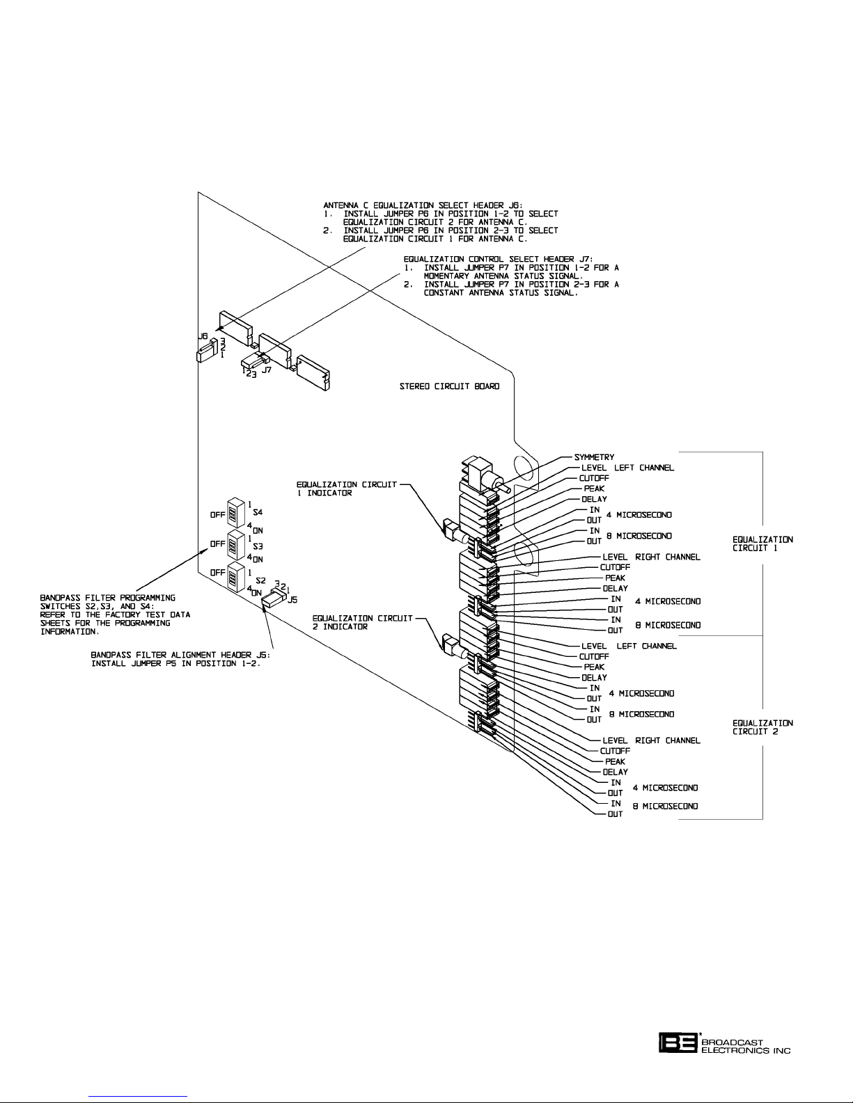
FIGURE 2-6. STEREO CIRCUIT BOARD PROGRAMMING
COPYRIGHT 1999 BROADCAST ELECTRONICS, INC
597-1111-6
2-13
Page 30
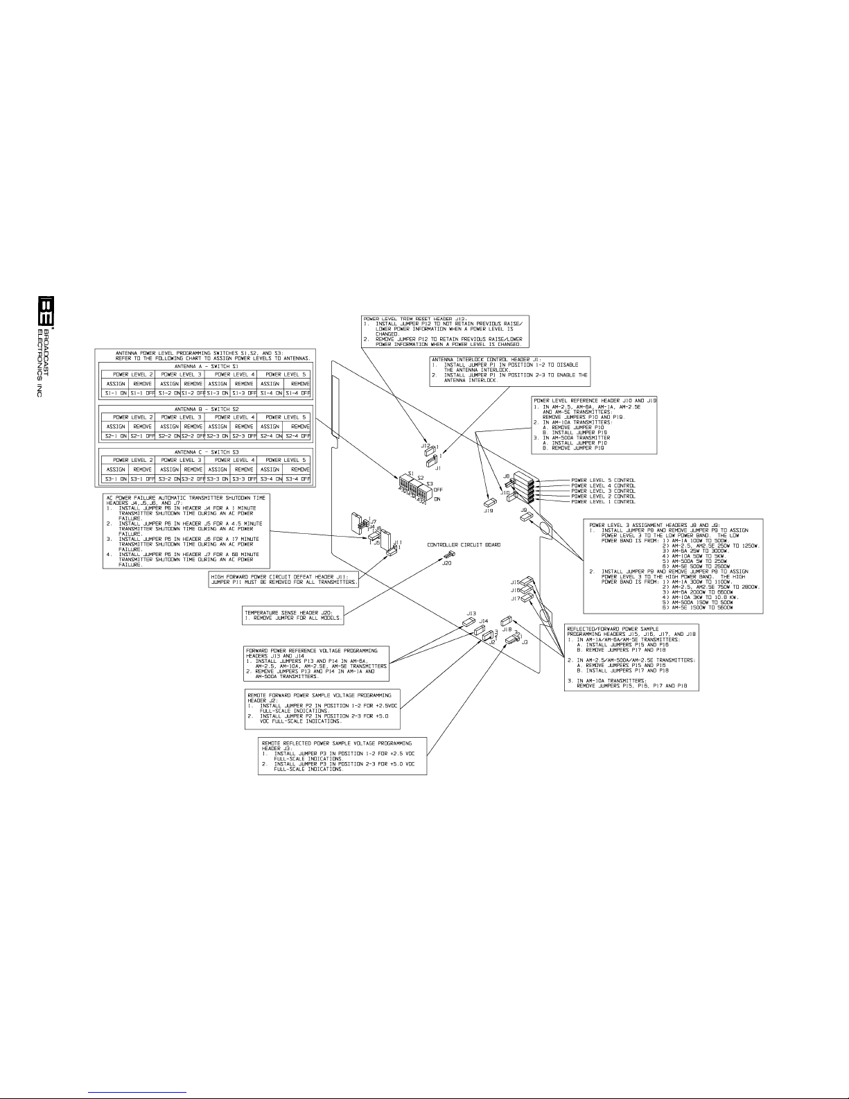
2-14
597-1112-5
FIGURE 2-7. CONTROLLER CIRCUIT BOARD PROGRAMMING
COPYRIGHT 1999 BROADCAST ELECTRONICS, INC
Page 31

2-47. Power Level Reference. Programmable headers J10 and J19 provide a reference for the
power level circuit. For AM-2.5E/AM-5E transmitters, ensure jumpers P10 and P19 are
removed.
2-48. Power Level 3 Assignment. Programmable header J8 and J9 control the assignment for
the power level 3 switch/indicator. For the AM-2.5E, the power level 3 switch/indicator
can be programmed to control power from: 1) 250 watts to 1250 watts or 2) 750 watts to
2800 watts. For the AM-5E, the power level 3 switch/indicator can be programmed to con
trol power from: 1) 500 watts to 2500 watts or 2) 1500 watts to 5600 watts. The power
level 3 switch/indicator is shipped from the factory to control power from: 1) 250 watts to
1250 watts on AM-2.5E models and 2) 500 watts to 2500 watts on AM-5E models. Pro
gram jumpers P8 and P9 as required.
2-49. Remote Reflected Power Sample Voltage Programming. Programmable header J3 con
trols the remote reflected power meter sample voltage. The remote reflected power sample
can be programmed for a +5.0 volt dc or +2.5 volt dc full-scale meter indications. The
transmitter is shipped from the factory programmed for +5.0 volt dc full-scale remote re
flected power meter indications.
2-50. Remote Forward Power Sample Voltage Programming. Programmable header J2 con
trols the remote forward power meter sample voltage. The remote forward power sample
can be programmed for a +5.0 volt dc or +2.5 volt dc full-scale meter indications. The
transmitter is shipped from the factory programmed for +5.0 volt dc full-scale remote for
ward power meter indications.
2-51. High Forward Power Defeat. Programmable header J11 controls the high forward power
detector circuit. Ensure jumper P11 is removed.
2-52. Reflected/Forward Power Sample Programming. Programmable headers J15, J16, J17,
and J18 control the reflected and forward power sample levels. Headers J15 and J17 con
trol the forward power sample. Headers J16 and J18 control the reflected power sample.
For AM-2.5E models: 1) remove jumpers P15 and P16 and 2) install jumpers P17 and P18.
For AM-5E models: 1) install jumpers P15 and P16 and 2) remove jumpers P17 and P18.
2-53. Forward Power Reference Voltage Programming. Programmable headers J13 and J14
establish the forward power reference level for a comparator circuit. For AM-2.5E/AM-5E
models, ensure jumpers P13 and P14 are installed.
2-54. Temperature Sense. Header J20 controls the temperature sense sample voltage. Ensure
P20 is removed for all models.
2-55.
POWER SUPPLY CIRCUIT BOARD. The power supply circuit board programming is pre
sented in the following text. Refer to the following text to check the power supply circuit
board programming.
2-56. Future Corrector Circuit. Programmable headers J9 and J10 establish parameters for a
future corrector circuit. Ensure jumper P9 is removed and P10 is installed.
2-57. Model Programming. Programmable headers J5 through J8 establish parameters for dif
ferent AM E-Series transmitters. Refer to the following text for the programming
information.
TRANSMITTER J5 J6 J7 J8
AM-2.5E Not Used Not Used Not Used Not Used
AM-5E Not Used Not Used Not Used Not Used
2-15
Page 32

2-58. REMOTE CONTROL.
WARNING
ENSURE PRIMARY POWER IS DISCONNECTED BE
FORE PROCEEDING.
WARNING
2-59. GENERAL. The AM-2.5E and AM-5E transmitters are designed for complete remote con
trol operations (refer to Figure 2-8 ). The transmitters will interface with almost any re
mote control unit such as the Broadcast Electronics model VMC-16 voice remote control
system. The following text presents a description of the transmitter remote control func
tions and indications. The remote control connections are located at 25-pin D-type con
nectors J1 and J2. J1/J2 are located on the transmitter top-panel. The remote control
functions are activated using a +5 to +15 volt dc signal. The remote indication functions:
1) require current limiting resistors and 2) provide up to 100 mA for indicators. A +5 volt
supply is provided at J1 for remote control operations.
2-60. Power Level Controls/Indicators. The transmitter is designed with five customer adjust
able operating power controls. The controls are located at J1-1 through J1-5. A +5 to +15
volt dc signal is required to activate the desired function.
2-61. Indications of power level control operations are located at J1-7 through J1-11. The power
level status indicators will go LOW (0 volts dc) when activated.
2-62. Transmitter Off Control/Indicator. The transmitter off control is located at J1-6. A +5 to
+15 volt dc signal is required to operate the transmitter to off. The indicator for the trans
mitter off control is located at J1-14. The off indicator will go LOW (0 volts dc) when acti
vated.
2-63. Power Level Raise/Lower Controls. The transmitter is designed with raise and lower con
trols to adjust the transmitter output power level. The controls are equipped with ability
to raise/lower power from 10% to 15% of the selected output power level. The controls are
located at J1-15 and J1-16. A +5 to +15 volt dc signal is required to activate the desired
function.
2-64. Antenna Interlock Input. The antenna interlock inputs are designed for the connection of
the status signals from antenna A, B, and C. The inputs are located at J1-19 through
J1-21. The inputs require a +5 to +15 volt dc signal to indicate an antenna ready status.
2-65. Transmitter Mute Input. The transmitter mute input is designed to mute the transmitter
when activated. The input is located at J1-22. The input requires a +5 to +15 volt dc sig
nal to mute the transmitter.
2-66. Remote Failsafe Input. The remote failsafe input is designed for the remote control unit
failsafe control line. The input is located at J1-23. The input requires a +5 to +15 volt dc
signal to indicate an enabled remote control unit.
2-67. External Interlock Input. The external interlock input is for the connection of an interlock
external to the transmitter. The input is located at J1-24. The input requires a +5 to +15
volt dc signal to indicate a closed interlock.
2-68. Interlock +5V. The interlock +5 volt supply is provided for the external interlock. The +5
volt supply is located at J1-25.
2-69. Exciter Mode Controls/Indicators. The transmitter exciter is designed to be operated in
the mono left, mono right, mono L+R, or stereo modes of operation. The controls are lo
cated at J2-1 through J2-4. A +5 to +15 volt dc signal is required to activate the desired
function.
2-70. Indications of exciter modes of operations are located at J2-5 though J2-8. The exciter
mode indicators will go LOW when activated.
2-71. Remote Forward/Reflected Power Meter Indications. Remote reflected power meter indi
cations are located at J2-9 and J2-10. The indications are designed to be programmed for
+5 volt dc full-scale meter indications or +2.5 volt dc full-scale meter indications.
2-16
Page 33
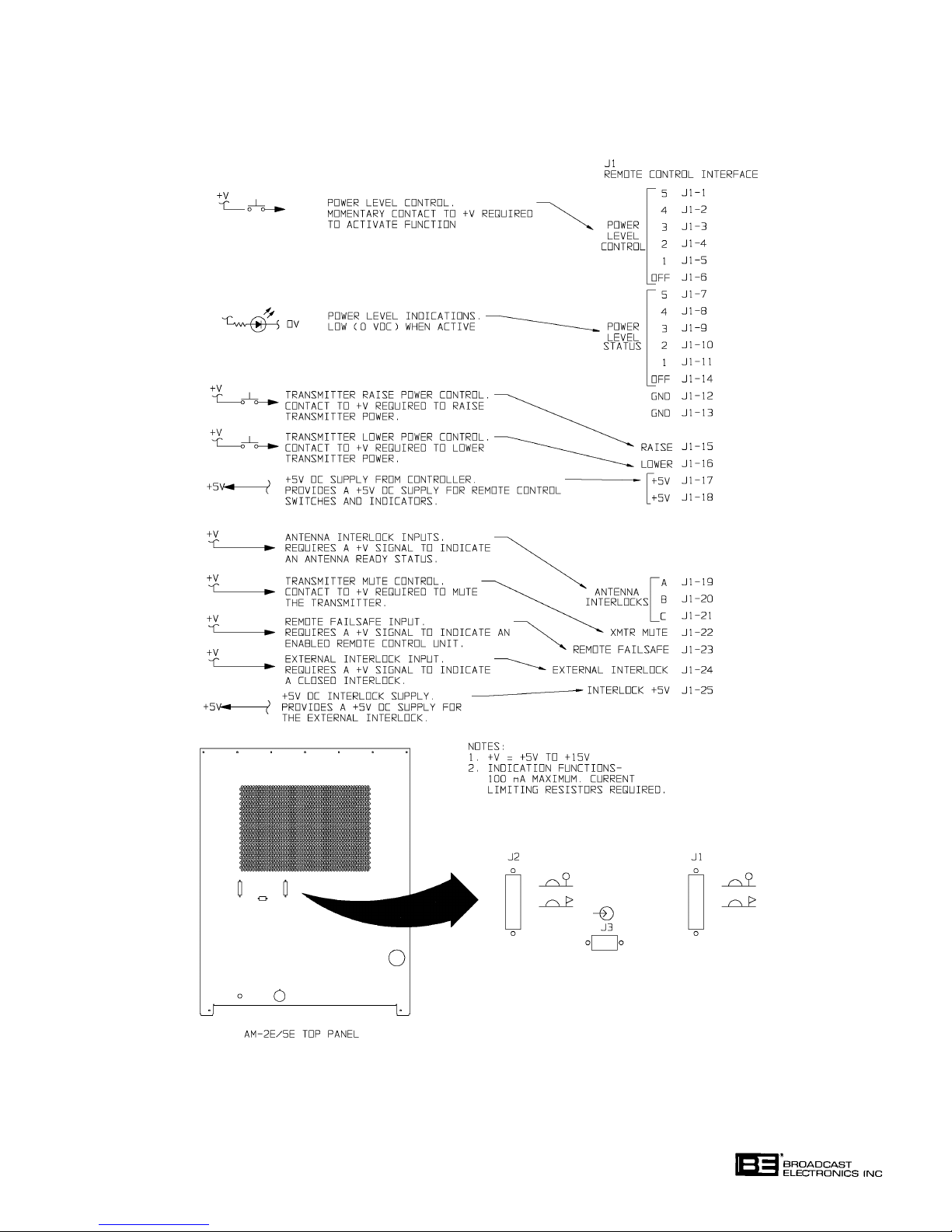
FIGURE 2-8. REMOTE CONTROL AND AUDIO CONNECTIONS (SHEET 1 OF 2)
COPYRIGHT 1999 BROADCAST ELECTRONICS, INC
597-1114-3
2-17
Page 34
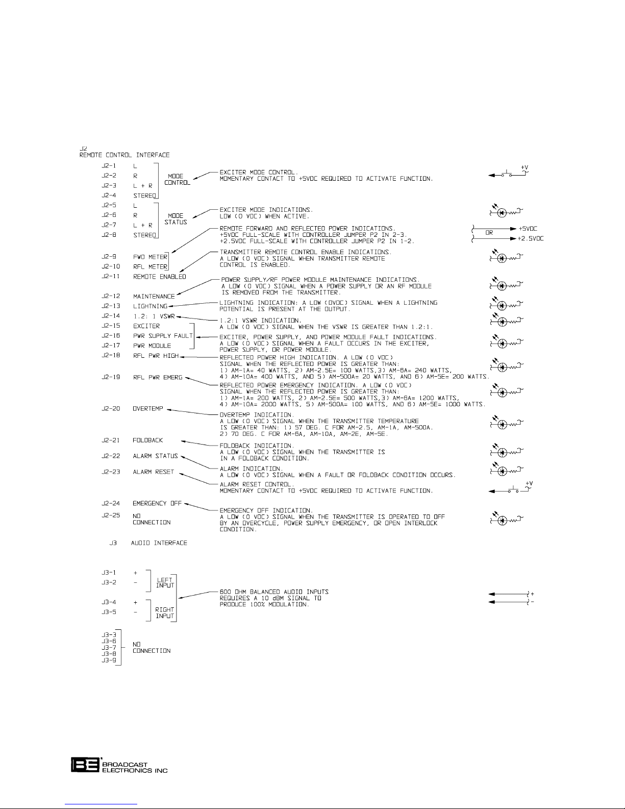
FIGURE 2-8. REMOTE CONTROL AND AUDIO CONNECTIONS (SHEET 2 OF 2)
COPYRIGHT 1999 BROADCAST ELECTRONICS, INC
597-1114-3A
2-18
Page 35

2-72. Remote Enabled Indications. The remote enabled indicator provides a signal to indicate
the status of transmitter remote control operations. The remote enabled indicator is lo
cated at J2-11. The indicator will go LOW to indicate when remote control operations are
enabled.
2-73. Maintenance Indications. The maintenance indicator provides a signal to indicate when
a transmitter power supply or an RF power module is removed from the transmitter for
maintenance. The maintenance indicator is located at J2-12. The indicator will go LOW
(0 volts dc) to indicate when a power supply is removed for maintenance.
2-74. Lightning Indications. The lightning indicator provides a signal to indicate when a greater
than: 1) 1500 volt potential is present at the output for AM-2.5E models or 2) 2100 volt
potential is present at the output for AM-5E models. The lightning indicator is located at
J2-13. The indicator will go LOW (0 volts dc) to indicate when a lightning potential is pre
sent at the transmitter output.
2-75. 1.2 : 1 VSWR Indications. The 1.2 : 1 VSWR indicator provides a signal to indicate when a
greater than 1.2 : 1 VSWR condition is present at the transmitter output. The 1.2 : 1 indi
cator is located at J2-14. The indicator will go LOW (0 volts dc) to indicate when a 1.2 : 1
VSWR condition is present at the transmitter output.
2-76. Exciter/PWR Supply/PWR Module Fault Indications. The exciter, power supply, and power
module fault indicators provide signals to indicate when an exciter, power supply, or a
power module fault has occurred. The exciter, power supply, and power module fault indi
cators are located at J2-15 through J2-17. The indicators will go LOW (0 volts dc) to
indicate when an exciter, power supply, or a power module fault has occurred.
2-77. RFL PWR High Indications. The reflected power high indicator provides a signal to indicate
when: 1) 100 watts of reflected power is present at the transmitter output for AM-2.5E
models or 2) 200 watts of reflected power is present at the transmitter output for AM-5E
models. The high reflected power indicator is located at J2-18. The indicator will go LOW
(0 volts dc) to indicate when a reflected power high condition is present at the transmitter
output.
2-78. RFL PWR Emergency Indications. The reflected power emergency indicator provides a sig
nal to indicate when greater than: 1) 500 watts of reflected power is present at the output
of the AM-2.5E transmitter or 2) 1000 watts of reflected power is present at the output of
the AM-5E transmitter. The reflected power emergency indicator is located at J2-19. The
indicator will go LOW (0 volts dc) to indicate when a reflected power emergency condition
is present at the transmitter output.
2-79. Overtemp Indications. The overtemp indicator provides a signal to indicate when the
transmitter temperature is greater than 70°C. The overtemp indicator is located at J2-20.
The indicator will go LOW (0 volts dc) to indicate when the transmitter temperature is
greater than 70°C.
2-80. Foldback Indications. The transmitter is designed to automatically reduce power when
one of the following fault condition occurs: 1) high reflected power, 2) high forward power,
3) high temperature, or 4) detection of a high voltage by the lightning circuit. The foldback
indicator is located at J2-21. The indicator will go LOW (0 volts dc) to indicate when the
transmitter is in a foldback condition.
2-81. Alarm Status Indications. The alarm status provides a signal to indicate when a fault or
foldback condition occurs. The alarm status indicator is located at J2-22. The indicator
will go LOW (0 volts dc) to indicate when the transmitter is in a fault or foldback condition.
2-82. Alarm Reset Control. The alarm reset control is designed to reset the fault detection cir
cuitry. The alarm reset control is located at J2-23. A +5 to +15 volt dc signal is required to
activate the function.
2-19
Page 36

2-83. Emergency Off Indications. The emergency off indicator provides a signal to indicate
when the transmitter is operated to off by any condition or event other than the use of the
off switch. These conditions/events include: 1) an overcycle off condition, 2) a power sup
ply emergency condition, or 3) an open interlock condition. A power supply emergency con
dition is when all the power supplies in the transmitter encounter faults. The emergency
off indicator is located at J2-24. The indicator will go LOW (0 volts dc) to indicate when an
emergency off condition is encountered.
2-84.
2-85. Wiring consists of connecting audio, the RF transmission line, and ac power to the trans
2-86. AUDIO INPUT CONNECTION. The AM-2.5E and AM-5E transmitters are equipped
WIRING.
mitter. Refer to the following text and connect the wiring to the transmitter.
with electronically balanced 600 Ohm left and right channel audio inputs. The audio in
puts are located on the transmitter top-panel at J3 (refer to Figure 2-8). The inputs are
designed to accept a +10 dBm signal at 600 Ohms.
WARNING
ENSURE PRIMARY POWER IS DISCONNECTED BE
FORE PROCEEDING.
WARNING
2-87. Audio is interfaced to the transmitter by: 1) selecting the appropriate cable and 2) connect
ing the cable to the terminals of 9-pin D-type connector J3. J3 is located on the transmit
ter top-panel. To interface audio to the transmitter: 1) use Belden 8760 cable or equiva
lent and 2) refer to Figure 2-8 and connect the audio to the transmitter as follows:
1. Connect the plus signal line to the + terminal.
2. Connect the minus signal line to the - terminal.
3. Connect the shield to ground at the audio source end.
2-88.
EXTERNAL STEREO RF INPUT. The transmitter is equipped with an external stereo RF
input on the transmitter top-panel (refer to Figure 2-9). The input is designed for the con
nection of an external stereo generator or reference oscillator with a signal level from 5 to
15 volts peak-to-peak. If an external stereo signal/reference is to be applied to the trans
mitter, connect the signal to the EXTERNAL RF INPUT connector on the transmitter
top-panel and program jumper P7 on the exciter circuit board in position 1-2.
2-89.
2-90.
2-91.
AM-2.5E/AM-5E RF TRANSMISSION LINE CONNECTION. The AM-2.5E/AM-5E
transmitter RF output connection is located on the transmitter top-panel (refer to Figure
2-9). The AM-5E requires 7/8 inch transmission line with a 7/16 male DIN connector.
The AM-2.5E requires 1/2 inch transmission line with a 7/16 male DIN connector. To con
nect the RF transmission line to the transmitter, refer to Figure 2-9 and connect the 7/16
male DIN type connector to the RF OUT connector on the transmitter top-panel.
EXTERNAL INTERLOCK. The AM-2.5E/AM-5E is equipped with an external interlock
such as for a test load. The interlock will turn off the transmitter RF output when opened.
The interlock is located at J1-24 and J1-25 on the transmitter top-panel. Refer to
External Interlock Input and Interlock +5v in the REMOTE CONTROL section of the
preceding text and perform the procedures to connect equipment to the transmitter exter
nal interlock.
MODULATION MONITOR. The modulation monitor connection is located on the trans
mitter top-panel. Refer to Figure 2-9 and connect the modulation monitor to the MOD
MONITOR SAMPLE OUTPUT receptacle.
2-20
Page 37
2-21
FIGURE 2-9. AM-2.5E/AM-5E RF OUTPUT CONNECTIONS
597-1114-22
COPYRIGHT 1999 BROADCAST ELECTRONICS, INC
Page 38
WARNING
WARNING
ENSURE PRIMARY POWER IS DISCONNECTED BE
FORE PROCEEDING.
WARNING
ENSURE AN EARTH GROUND CONDUCTOR IS SE
CURELY CONNECTED TO THE TRANSMITTER AC
WARNING
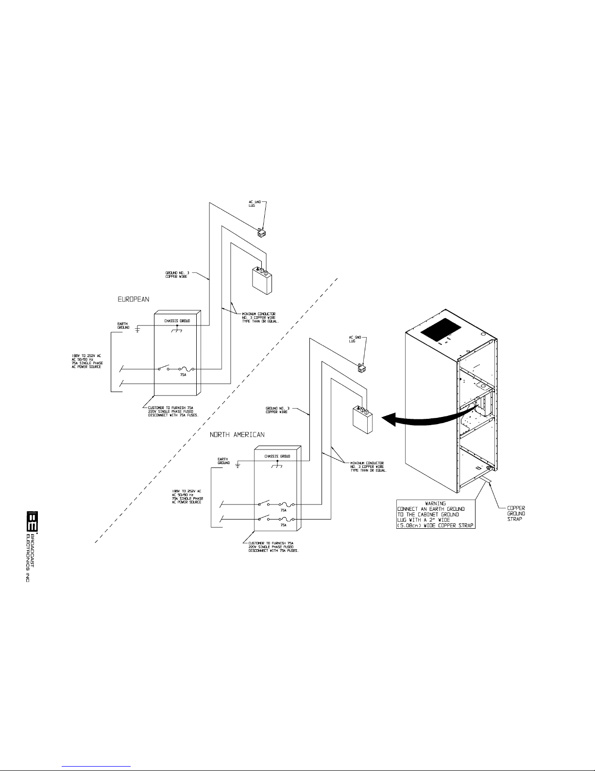
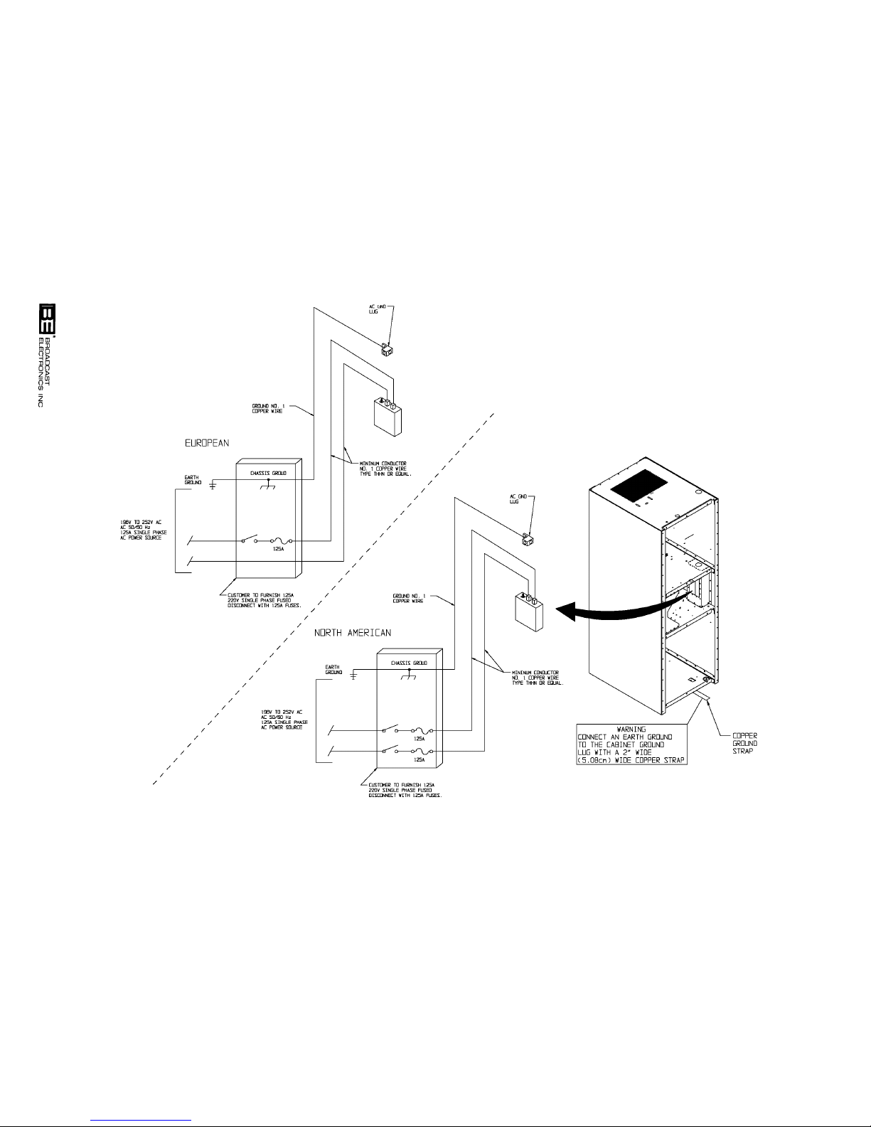
2-92. AC POWER CONNECTIONS. The AM-2.5E transmitter requires a single-phase source
of 196V to 252V ac, 50 Hz or 60 Hz at 75 Amperes. The AM-5E transmitter requires a
single-phase source of 196V to 252V ac, 50 Hz or 60 Hz at 125 amperes. For operating
safety, the power source must be routed to the transmitter through a fused power discon
nect (refer to Figures 2-10 and 2-11).
WARNING
GROUND LUG.
ENSURE PRIMARY POWER IS DISCONNECTED BE
FORE PROCEEDING.
WARNING
2-93. Main ac Input -AM-2.5E. Refer to Figure 2-10 and connect the 75 Ampere service to ac
input/control device S1 through a fused service disconnect as shown. Ensure a utility com
pany ground conductor is securely connected to the transmitter common ground system
and the ac service ground wire is securely connected to the ac ground lug as shown.
2-94. Main ac Input - AM-5E. Refer to Figure 2-11 and connect the 125 ampere service to ac
input/control device S1 through a fused service disconnect as shown. Ensure a utility com
pany ground conductor is securely connected to the transmitter common ground system
and the ac service ground wire is securely connected to the ac ground lug as shown.
WARNING
ENSURE PRIMARY POWER IS DISCONNECTED BE
FORE PROCEEDING.
WARNING
WARNING
ENSURE AN EARTH GROUND CONDUCTOR IS SE
CURELY CONNECTED TO THE TRANSMITTER
WARNING
2-95. GROUND. The transmitter is equipped with a cabinet ground system for operating safety.
The ground system requires the connection of an earth ground. Refer to Figures 2-10 and
2-11 and connect an earth ground to the cabinet ground lug as shown using a 2 inch (5.08
cm) wide copper strap.
2-96.
TRANSMITTER SITE LIGHTNING PROTECTION SYSTEM CHECKOUT.
CAUTION
GROUND LUG.
THE TRANSMITTER SITE LIGHTNING PROTECTION
SYSTEM MUST BE INSPECTED AND IN PROPER
CAUTION
WORKING CONDITION FOR RELIABLE TRANSMIT
TER OPERATION.
2-97. For reliable transmitter operation, the transmitter site lightning protection system must
be inspected and in proper working condition. Due to the solid-state design of the trans
mitter, high voltage potentials from lightning activity can cause severe damage to the
transmitter circuitry. Therefore, perform the following procedures to inspect and improve
the lightning protection system at the transmitter site. Refer to the NAB Radio Handbook
for additional transmitter site lightning protection system information.
2-22
Page 39
2-23
FIGURE 2-10. AM-2.5E PRIMARY AC WIRING
597-1114-10
COPYRIGHT 1999 BROADCAST ELECTRONICS, INC
Page 40
2-24
FIGURE 2-11. AM-5E PRIMARY AC WIRING
COPYRIGHT 1999 BROADCAST ELECTRONICS, INC
597-1114-9
Page 41

2-98. ANTENNA BALL-GAP LIGHTNING ARRESTOR. Each tower in the antenna system must
be equipped with a ball-gap lightning arrestor (refer to Figure 2-12). The ball-gap
arrestor is designed to safely conduct lightning potentials to ground. Inspect the ball-gap
arrestors by performing the following procedures.
2-99. Ball-Gap Position. The antenna ball-gap lightning arrestor must be aligned horizontally.
Do not align the ball-gaps vertically. Vertical alignment allows rain water to collect on the
balls. This reduces the gap separation and results in arcing during rain activity.
2-100. Ball-Gap Separation. The antenna ball-gap lightning arrestor must be adjusted for the
proper separation. If the ball-gap separation is too wide, the arrestor will not function. If
the ball-gap separation is too narrow, the arrestor will arc during normal transmitter op
eration. As a general rule: 1) a separation of approximately 0.020 in. for each peak kilo
volt at the transmitter tower is required or 2) 0.125 inch for each 9.4 peak kilovolt at the
transmitter tower is required.
2-101. The recommended method for ball-gap separation adjustment is to adjust the gap to pre
vent arcing during peak modulation activity. To adjust the separation, proceed as follows:
1. Adjust the ball-gap separation using the general rule presented in the preceding
text.
2. Operate the transmitter at peak modulation and check the ball-gap for arcing
activity.
WARNING
DISCONNECT ALL TRANSMITTER PRIMARY POWER
BEFORE PROCEEDING.
WARNING
3. Operate the transmitter to off.
4. Adjust the ball-gap separation as follows:
A. If no arcing activity is detected, reduce the ball-gap separation.
B. If arcing activity is detected, increase the ball-gap separation.
5. Repeat the procedure until the ball-gap separation is adjusted for the smallest gap
possible without arcing during peak modulation activity.
2-102. ANTENNA-TUNING-UNIT SPARK-GAP LIGHTNING ARRESTOR. The
antenna-tuning-unit (ATU) must be equipped with a spark-gap lightning arrestor (refer
to Figure 2-12). The spark-gap arrestor can be: 1) a ball-gap type or 2) a horn type. Ad
just the spark-gap for the smallest possible gap without arcing during peak modulation
activity.
2-103.
TRANSMITTER SITE GROUNDING SYSTEM. The transmitter site grounding system must
be properly connected for reliable transmitter operation. A typical transmitter site ground
ing system is shown in Figure 2-12. Perform the following procedures to ensure the
grounding system connections are secure.
1. Ensure the antenna base ground strap is securely connected to the antenna ground
plane radials.
2. Ensure the antenna ball-gap lightning arrestor is securely connected to the
lightning ground rod system and to the antenna ground plane radials.
3. Ensure the ATU ground and the station RF ground is securely connected to the
antenna ground plane radials.
2-25
Page 42

2-104. CABLE PROTECTION. The ac line cable, audio/control cables, and the RF output trans
mission line require a combination of MOV and ferrite core protection to prevent the entry
of lightning potentials (refer to Figure 2-12). Refer to the following text to install MOV
and ferrite cores on the cables to prevent the conductance of lightning potentials. Ensure
MOVs are connected from the ac line and audio/control cable conductors to the station RF
ground as shown. The MOVs should be rated for 20,000 Ampere surges
(BE P/N 140-0032).
2-105. Ferrite Core. The ac line cable, the audio/control cables, and the RF output transmission
line also require the placement of ferrite cores. The cores are designed to create a high
impedance for undesired current paths such as lightning. Ferrite cores for placement on ac
line audio/control and RF output transmission line cables are located in the accessory parts
kit. Locate the ferrite cores and install the cores by performing the following procedures.
2-106. Modulation Monitor Core. One 375-0009-001 ferrite core is designed to be installed on
the modulation monitor cable. Install the core on the modulation monitor cable by:
1) routing the cable through the core and 2) wrapping the cable to create one cable loop
around the core. The core can be installed at any location on the cable.
2-107. Audio/Remote Control/Status Core. A second 375-0009-001 ferrite core is designed to be
installed on the audio and remote control/status cables. Install the core on the audio and
remote control/status cables by: 1) routing the cables through the core and 2) if possible,
wrapping the cables to create one cable loop cable around the core. The core can be
installed at any location on the cables.
2-108. Ac Input Core. A 375-0007-001 ferrite core is shipped with the unit for installation on
the transmitter ac input cable. Install the core by routing: 1) all ac line phase cables
through the core or 2) all ac line phase cables and ground cable through the core. Place the
core at any location between the wall mounted fused disconnect and the transmitter ac in
put switch.
2-109. RF Output Core. A second 375-0007-001 ferrite core is designed to be installed on the
transmitter RF output transmission line cable. Install the core by routing the RF output
cable through the core. Place the core at any location between the transmitter RF output
connector and the next equipment connection in the RF output system such as the antenna
phasing system. It is recommended the core be placed outside the transmitter cabinet.
2-110. ANTENNA RF FEED LINE. Check the antenna RF feed line between the ATU and the
tower. Ensure the line contains one or more one foot diameter loops. The loops function as
a series inductance and increase the impedance of the line.
2-111. TRANSMISSION LINE AND ANTENNA CHECKOUT.
CAUTION
CAUTION
2-112. The transmission line and antenna must be inspected and in proper working condition for
reliable transmitter operation. Perform the following procedures to inspect the transmis
sion line and antenna.
2-113.
2-114.
ANTENNA VSWR. The AM-2.5E/AM-5E are designed to operate into an antenna with a
maximum VSWR of 1.5 : 1. Check the antenna VSWR. If the VSWR is greater than
1.5 : 1, contact the Broadcast Electronics Customer Service Department. Typically, the an
tenna will require the installation of an additional tuning unit to reduce the antenna
VSWR.
COAXIAL SWITCH CONTROLLER. To prevent damage to the transmitter, the transmit
ter must be muted during any antenna change sequence. Inspect the motorized coaxial
switch controller and ensure the unit outputs a +5 volt to +15 volt mute signal. Ensure the
mute signal is applied to the transmitter.
THE TRANSMISSION LINE AND ANTENNA MUST BE
INSPECTED AND IN PROPER WORKING CONDITION
FOR RELIABLE TRANSMITTER OPERATION.
2-26
Page 43
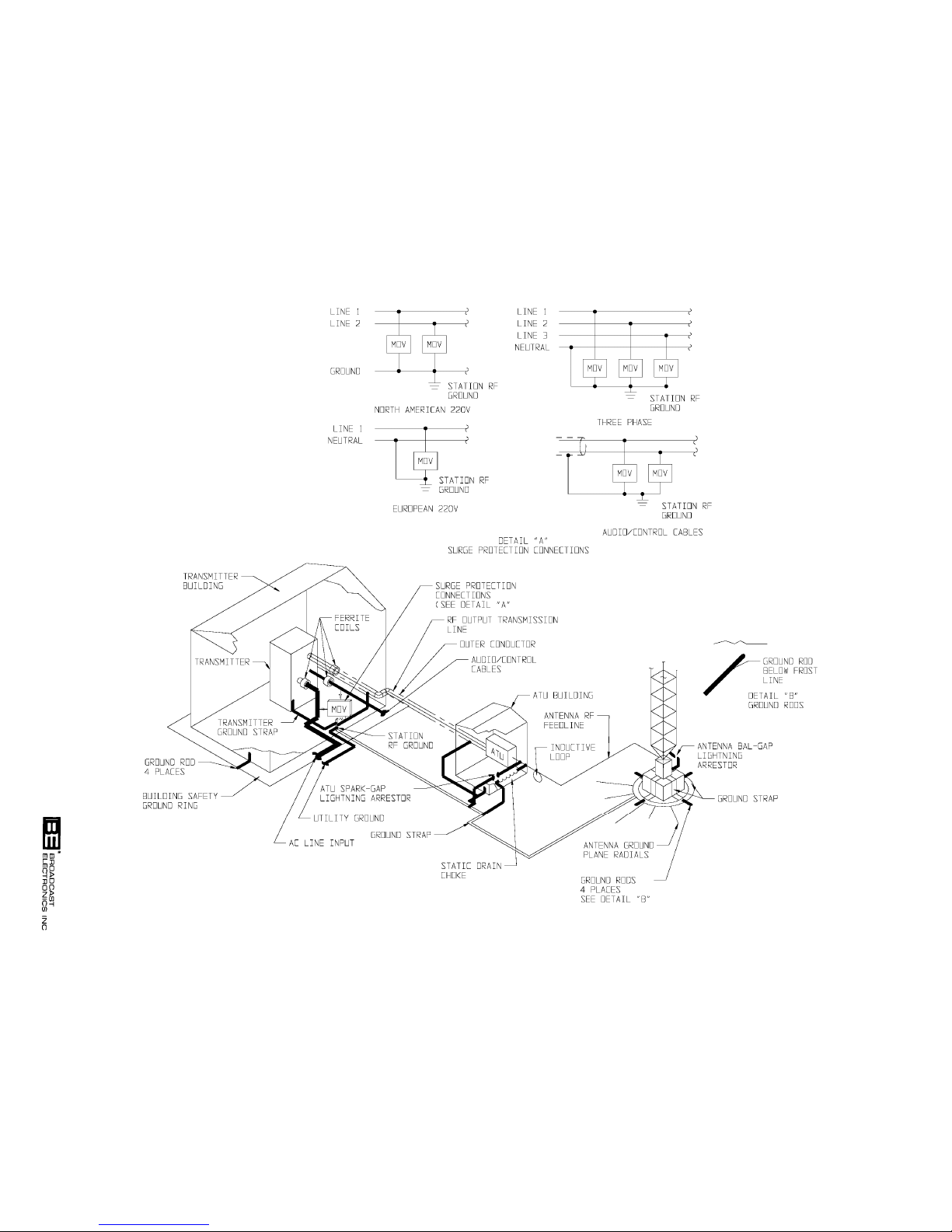
2-27
FIGURE 2-12. ANTENNA LIGHTNING PROTECTION SYSTEM
597-1111-36
COPYRIGHT 1999 BROADCAST ELECTRONICS, INC
Page 44

2-115. ATU AND PHASOR CHECKOUT. Inspect the ATU and the antenna phasor unit (if
installed in the system) for arcing activity during peak modulation periods. Repair or re
place any devices to prevent arcing during peak modulation periods.
2-116.
INITIAL CHECKOUT.
WARNING
ENSURE PRIMARY POWER IS DISCONNECTED BE
FORE PROCEEDING.
WARNING
2-117. Prior to performing the preliminary operating procedures, the transmitter should be
checked to ensure all installation and connection procedures have been performed. To
check the transmitter, proceed as follows:
A. Ensure all ECU circuit boards, RF power modules, and power supply circuit boards
are installed.
B. Ensure the RF output transmission line is connected to the transmitter output
network.
C. Ensure the station earth ground is connected to the transmitter ground terminal.
D. Ensure all audio and control cables are connected to the transmitter.
E. Ensure the modulation monitor is connected to the transmitter.
F. Ensure all ac power connections are secure.
G. Ensure the station RF output transmission line system and antenna are in proper
working condition.
H. Ensure the antenna lightning protection system is in proper working condition.
2-118.
2-119. Adjust the transmitter for operation with the equipment at the installation site as follows:
PRELIMINARY OPERATION AND ADJUSTMENT.
WARNING
THE TRANSMITTER POWER SUPPLY OPERATES
FROM A HIGH FLOATING GROUND POTENTIAL.
WARNING
NEVER OPERATE THE TRANSMITTER WITH THE
REARDOOR OPEN.
2-120. TUNING. The transmitter must be adjusted to operate into the station antenna. To tune
the transmitter, proceed as follows:
2-121. Operate the rear-door ac on/off switch to ON. The ECU and power module front-panel
indicators will illuminate.
2-122. Depress the power level 1 switch/indicator to illuminate the switch/indicator.
2-123. Operate the FORWARD POWER meter switch to LOW and observe the forward power
indication.
2-124. Operate the REFLECTED POWER meter switch to LOW and observe the reflected power
indication.
2-125. Tune the transmitter by adjusting the TUNING and LOADING controls as required for a
minimum reflected power indication on the REFLECTED POWER meter.
2-28
Page 45
2-126. POWER LEVEL AND MODULATION MONITOR CALIBRATION ADJUSTMENTS. The
transmitter power levels are adjusted to the levels specified in the sales order at the
factory. If no power levels are specified, the levels are adjusted as follows:
AM-2.5E AM-5E
Power level 1 = 500 watts Power level 1 = 1000 watts
Power level 2 = 1000 watts Power level 2 = 2000 watts
Power level 3 = 1500 watts Power level 3 = 3000 watts
Power level 4 = 2000 watts Power level 4 = 4000 watts
Power level 5 = 2500 watts Power level 5 = 5000 watts
2-127. If desired, the transmitter power levels can be changed at any time. If the transmitter
power levels are adjusted, the modulation monitor output must also be re-calibrated. To
change the power level and re-calibrate the modulation monitor output, proceed as follows:
WARNING
DISCONNECT ALL TRANSMITTER PRIMARY POWER
BEFORE PROCEEDING.
WARNING
2-128. Operate the transmitter rear-door ac on/off control switch to OFF and open the rear-door.
2-129. Refer to Figure 2-13 and connect the test equipment to the transmitter modulation connec
tor as shown.
2-130. Operate the transmitter rear-door ac on/off control switch to ON.
2-131. Depress power level control 1 switch/indicator to illuminate the switch/indicator.
2-132. Operate the FORWARD POWER meter switch to LOW or HIGH as required and observe
the forward power indication.
2-133. Refer to Figure 2-7 and adjust the power level 1 control to obtain the desired indication on
the FORWARD POWER meter. The control range is from: 1) 250 watts to 1250 watts on
AM-2.5E models and 2) 500 watts to 2500 watts on AM-5E models.
2-134. Refer to Figure 3-1 in SECTION III, OPERATION and adjust the power level 1 modula
tion monitor calibration control for a 5.7 volt peak-to-peak signal on the oscilloscope.
2-135. Repeat the procedure for power levels 2 through 5. The power level control ranges are as
follows:
AM-2.5E
1. Power level 2 - 250 watts to 1250 watts.
2. Power level 3 - 250 watts to 1250 watts or 750 watts to 2800 watts as
programmed by a jumper on the controller circuit board.
3. Power level 4 - 750 watts to 2800 watts.
4. Power level 5 - 750 watts to 2800 watts.
1. Power level 2 - 500 watts to 2500 watts.
2. Power level 3 - 500 watts to 2500 watts or 1500 watts to 5600 watts as
3. Power level 4 - 1500 watts to 5600 watts.
4. Power level 5 - 1500 watts to 5600 watts.
AM-5E
programmed by a jumper on the controller circuit board.
2-29
Page 46
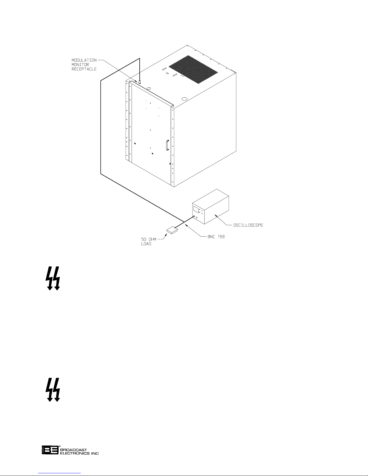
COPYRIGHT 1999 BROADCAST ELECTRONICS, INC
597-1114-11
FIGURE 2-13. TEST EQUIPMENT CONNECTIONS, POWER LEVEL CALIBRATION
WARNING
DISCONNECT ALL TRANSMITTER PRIMARY POWER
BEFORE PROCEEDING.
WARNING
2-136. Operate the transmitter rear-door ac on/off control switch to OFF.
2-137. Disconnect the cable from the transmitter modulation monitor connector.
2-138. STEREO ADJUSTMENT. If the transmitter is operated in the stereo mode, the transmitter
stereo circuitry must be adjusted to compensate for antenna system variances. The pri
mary objective in the adjustment of the transmitter is to configure the stereo circuitry to
minimize distortion and maximize separation across the entire audio band. A proof of per
formance sheet is provided at the end of this section to record performance measurements.
To adjust the stereo circuitry, perform the following procedures and record the measure
ments on the proof of performance sheet at the end of this section.
WARNING
DISCONNECT ALL TRANSMITTER PRIMARY POWER
BEFORE PROCEEDING.
WARNING
2-139. Operate the transmitter rear-door ac on/off control switch to OFF.
2-140. Refer to Figure 2-14 and connect the test equipment as shown.
2-30
Page 47
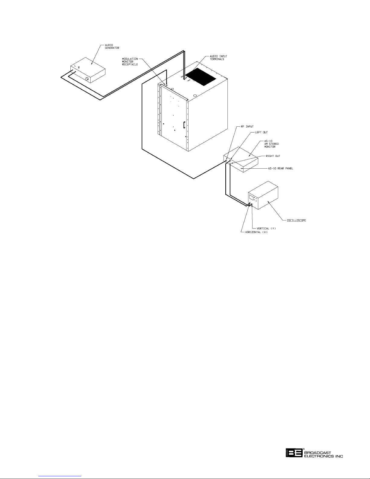
COPYRIGHT 1999 BROADCAST ELECTRONICS, INC
597-1114-12
FIGURE 2-14. TEST EQUIPMENT CONNECTIONS, SEPARATION
2-141. Operate the oscilloscope for: 1) 200 mV/div sensitivity and 2) dc coupled.
2-142. Refer to Figure 2-8 and connect an audio generator to the audio input terminals.
2-143. Operate the transmitter rear-door ac on/off control switch to ON.
2-144. Select the antenna which is configured for equalization circuit 1 operation (refer to STE
REO CIRCUIT BOARD PROGRAMMING in the preceding text if required) and determine
a power level.
2-145. Depress the desired power level switch/indicator to illuminate the switch/indicator.
2-146. Refer to SECTION III, OPERATION and perform the following:
1. Operate the stereo circuit board mode control switch to illuminate the stereo
indicator. When power is applied to the transmitter, the stereo circuit board will
automatically be configured to the stereo mode.
2. Operate the stereo circuit board pilot switch to off.
3. Ensure the equalization circuit 1 indicator on the stereo circuit board is
illuminated.
2-147. Adjust equalization circuit 1 as follows:
1. Adjust the audio generator for a 1 KHz left channel output at +10 dBm and
observe the lissajous pattern displayed on the oscilloscope.
2-31
Page 48

2. Refer to Figure 2-6 and adjust the left channel level control to obtain a horizontal
lissajous pattern (refer to Figure 2-15).
3. Adjust the group delay as follows:
A. Configure the group delay circuitry for adjustment as follows:
1. Refer to Figure 2-6 and configure the left channel 4 microsecond and
8 microsecond sections to in.
2. Refer to Figure 2-6 and operate the left channel delay control fully counterclockwise.
B. Refer to Figure 2-6 and adjust the left channel delay control to close the oscillo-
scope display and obtain a straight-line lissajous display as shown in the maximum left channel separation lissajous pattern (refer to Figure 2-15). If the
display will not close, proceed as follows:
1. Refer to Figure 2-6 and: 1) configure only the 8 microsecond delay section
to in and 2) adjust the left channel delay control to close the oscilloscope
display.
2. If the display will not close refer to Figure 2-6 and: 1) configure only the 4
microsecond delay section to in and 2) adjust the left channel delay control to
close the oscilloscope display.
4. Adjust the separation at 7 kHz as follows:
A. Adjust the audio generator for a 7 kHz left channel output at +10 dBm.
B. Refer to Figure 2-6 and adjust the left channel cutoff and peak controls to
obtain a maximum left channel separation lissajous pattern as shown in
Figure 2-15.
C. If a maximum left channel lissajous pattern can not be obtained, refer to Figure
2-6 and adjust the left channel delay control to close the oscilloscope display
and obtain a straight-line lissajous pattern (refer to Figure 2-15).
5. Repeat the entire procedure for the right channel. Adjust the right channel level,
cutoff, peak, and delay controls as required to obtain optimum separation and
distortion from the right channel.
6. Repeat the entire procedure for equalization circuit 2. Adjust the equalization
circuit 2 using the equalization 2 left/right channel level, cutoff, peak, delay,
controls and the equalization 2 group delay sections to obtain optimum separation
and distortion.
2-148. Once the stereo adjustment is complete: 1) refer to SECTION III, OPERATION and oper
ate the pilot switch on the stereo circuit board to ON and 2) remove the test equipment.
2-149.
SINGLE CHANNEL LEVEL. The transmitter is equipped with a single channel level con
trol. When the transmitter is operating in the stereo mode, the level control is designed to
boost a remaining audio channel level in the event of a failure in one channel. For trans
mitters operating in the stereo mode, adjust the single channel level control as follows:
2-32
Page 49
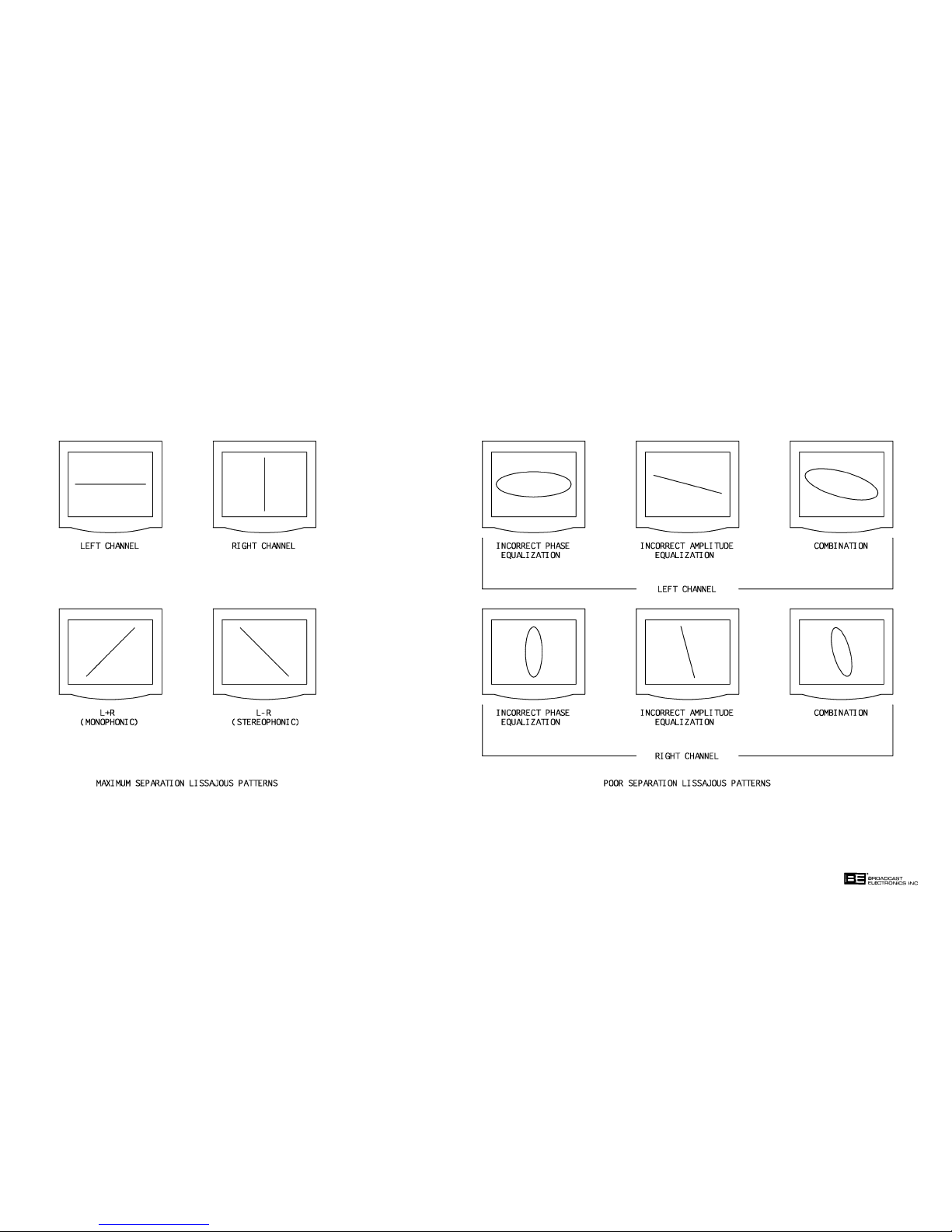
597-0095-19
FIGURE 2-15. EQUALIZATION LISSAJOUS PATTERNS
(2-33/2-34)
COPYRIGHT 1999 BROADCAST ELECTRONICS, INC
Page 50

WARNING
DISCONNECT ALL TRANSMITTER PRIMARY POWER
BEFORE PROCEEDING.
WARNING
2-150. Operate the transmitter rear-door ac on/off control switch to OFF.
2-151. If an audio processor is used with the transmitter, ensure the processor is connected as fol
lows:
1. Ensure normal program audio is connected to the processor input.
2. Ensure the audio processor output is connected to the transmitter audio input.
2-152. Operate the transmitter rear-door ac on/off control switch to ON.
2-153. Depress a desired power level switch/indicator to illuminate the switch/indicator.
2-154. Refer to SECTION III, OPERATION and operate the stereo circuit board mode control
switch to illuminate the stereo indicator.
2-155. Disable one channel applied to the transmitter.
2-156. If an audio processor is used with the transmitter, refer to the audio processor manual and
adjust the processor single channel limiter as described in the procedure.
2-157. Refer to SECTION III, OPERATION and operate the stereo circuit board mode control
switch to illuminate the mono left or mono right indicator as determined by the remaining
operating audio channel applied to the transmitter.
2-158. Refer to Figure 2-5 and adjust the single channel level control on the exciter circuit board
as required to obtain an approximate 100% modulation indication on the modulation moni
tor.
2-35
Page 51

SECTION III
OPERATION
3-1. INTRODUCTION.
3-2. This section identifies all controls and indicators associated with the AM-2.5E/AM-5E
transmitters and provides standard operating procedures.
3-3. CONTROLS AND INDICATORS.
3-4. Figures 3-1, 3-2, and 3-3 present the location of all controls and indicators associated with
normal operation of the AM-2.5E and AM-5E transmitters. Tables 3-1, 3-2, and 3-3
present the functions of each control or indicator. Refer to Figures 3-1 through 3-3 and
Tables 3-1 through 3-3 for a description of the controls and indicators associated with the
AM-2.5E/AM-5E transmitters.
TABLE 3-1. AM-2.5E/AM-5E CONTROLS AND INDICATORS
(Sheet 1 of 2)
INDEX
NO. NOMENCLATURE FUNCTION
1 FORWARD POWER Displays the transmitter forward power output in
Meter watts as selected by the FORWARD POWER Meter
LOW/HIGH/OFF switch.
2 FORWARD POWER Configures the FORWARD POWER meter: 1) to
Meter HIGH/LOW/OFF display forward power information on the HIGH
Switch scale, 2) to display forward power information on the
LOW scale, or 3) to off. In the AM-2.5E: 1) the HIGH
scale is from 0 to 3000 watts and 2) the LOW scale is
from 0 to 750 watts. In the AM-5E: 1) the HIGH
scale is from 0 to 6000 watts and 2) the LOW scale is
from 0 to 1500 watts.
3 REFLECTED POWER Displays the transmitter reflected power output in
Meter watts or the ac input voltage in volts as selected by
the REFLECTED POWER HIGH/LOW/VAC
Switch.
4 REFLECTED POWER Configures the REFLECTED POWER meter to
Meter HIGH/LOW/VAC display: 1) reflected power information on the HIGH
Switch scale, 2) reflected power information on the LOW
scale, or 3) the ac input voltage. In the AM-2.5E:
1) the HIGH scale is from 0 to 300 watts and 2) the
LOW scale is from 0 to 60 watts. In the AM-5E:
1) the HIGH scale is from 0 to 600 watts and 2) the
LOW scale is from 0 to 150 watts. The ac volts scale is
from 150 to 300 volts.
3-1
Page 52
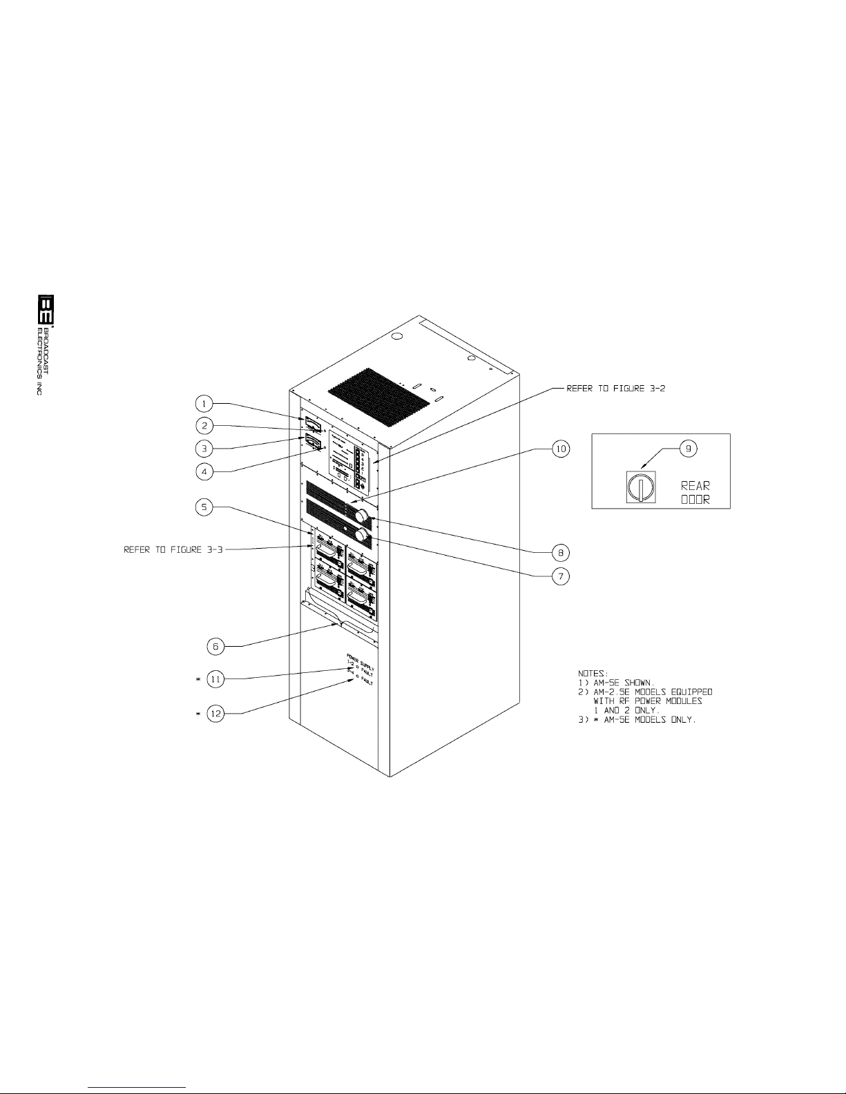
3-2
597-1114-13
FIGURE 3-1. AM-2.5E/AM-5E CONTROLS AND INDICATORS
COPYRIGHT 1999 BROADCAST ELECTRONICS, INC
Page 53
TABLE 3-1. AM-2.5E/AM-5E CONTROLS AND INDICATORS
(Sheet 2 of 2)
INDEX
NO. NOMENCLATURE FUNCTION
5 RF POWER MODULE A modular plug-in assembly containing two RF
power amplifier circuit boards and one modulator
circuit board. The AM-2.5E is equipped with 2 power
modules. The AM-5E is equipped with 4 power
modules. Each power module is designed to output
1375 watts of RF power.
6 POWER BLOCK An RF power amplifier assembly containing two RF
power modules and a combiner unit.
7 LOAD Control Operates in association with the TUNE control to
match the transmitter output impedance to the
antenna.
8 TUNE Control Operates in association with the LOAD control to
match the transmitter output impedance to the
antenna.
9 AC ON/OFF Controls the application of ac power to the transmit-
Switch ter.
10 Modulation Monitor Calibrates the modulation monitor sample to power
Calibration Controls levels 1 through 5.
11 POWER SUPPLY 1-2 Illuminates to indicate a failure in the 1-2 power
Fault Indicator supply. The supply provides power for RF power
(AM-5E Only) modules 1-2.
12 POWER SUPPLY 3-4 Illuminates to indicate a failure in the 3-4 power sup-
Fault Indicator ply. The supply provides power for RF power modules
(AM-5E Only) 3-4.
TABLE 3-2. ECU CONTROLS AND INDICATORS
(Sheet 1 of 6)
INDEX
NO. NOMENCLATURE FUNCTION
1 EXCITER Indicator Displays the operating status of the exciter.
GREEN Display - Indicates normal exciter
operation.
RED Display - Indicates an exciter fault.
3-3
Page 54

TABLE 3-2. ECU CONTROLS AND INDICATORS
(Sheet 2 of 6)
INDEX
NO. NOMENCLATURE FUNCTION
2 POWER MODULES Displays the operating status of the transmitter
Indicator power modules.
GREEN Display - Indicates all power modules are
operating normally.
YELLOW Display - Indicates an RF power module is
removed from the transmitter.
RED Display - Indicates a fault in an RF power
module.
3 POWER SUPPLY Displays the operating status of the transmitter
Indicator power supply system.
GREEN Display - Indicates normal power supply
system operation.
YELLOW DISPLAY - Indicates one or more power
supplies are removed from the transmitter.
RED Display - Indicates a power supply system
fault.
4 ANTENNA VSWR Displays the condition of the antenna system.
Indicator
GREEN Display - Indicates a normal antenna load.
YELLOW Display - Indicates a VSWR condition
of 1.2 : 1.
RED Display - Indicates a high reflected/forward
power indication. In the AM-2.5E, indicates a 100
watt reflected power condition or a condition which
results in a high forward power indication of greater
than 20%. In the AM-5E, indicates a 200 watt
reflected power condition or a condition which results
in a high forward power indication of greater than
20%.
FLASHING RED Display - Indicates a reflected
power emergency condition. In the AM-2.5E,
indicates a 500 watt reflected power condition. In
the AM-5E, indicates a 1000 watt reflected power
condition.
3-4
Page 55
TABLE 3-2. ECU CONTROLS AND INDICATORS
(Sheet 3 of 6)
INDEX
NO. NOMENCLATURE FUNCTION
5 POWER CONTROL SWITCHES - A group of five switches designed to
Switch/Indicators select five customer adjustable transmitter operating
output power levels.
In the AM-2.5E, switches 1 and 2 can be adjusted to
obtain output power levels from 250 to 1250 watts.
Switches 4 and 5 can be adjusted to obtain output
power levels from 750 to 2800 watts. Switch 3 is
designed to be customer assigned to control power in
the 250 to 1250 watt range or the 750 to 2800 watt
range.
In the AM-5E, switches 1 and 2 can be adjusted to
obtain output power levels from 500 to 2500 watts.
Switches 4 and 5 can be adjusted to obtain output
power levels from 1500 to 5600 watts. Switch 3 is
designed to be customer assigned to control power in
the 500 to 2500 watt range or the 1500 to 5600 watt
range.
INDICATORS - Illuminates to indicate an associated
power control switch has been selected.
6 OFF Switch/Indicator SWITCH - Deenergizes the transmitter RF output
power and configures the unit to off.
INDICATOR - Illuminates to indicate the OFF
switch has been selected.
7 POWER Switch/ SWITCH - Instructs the system controller to raise
Indicator the transmitter output power. The switch is designed
with the ability to raise power from 10% to 15% of the
selected output power level.
INDICATOR - During manual operating conditions,
illuminates to indicate the POWER switch is
selected. During automatic raise conditions, the indicator will illuminate to indicate the rate of automatic
power increase.
8 POWER Switch/ SWITCH - Instructs the system controller to lower
Indicator the transmitter output power. The switch is designed
with the ability to lower power from 10% to 15% of the
selected output power level.
INDICATOR - During manual operating conditions,
illuminates to indicate the POWER switch is
selected. During automatic lower conditions, the
indicator will illuminate to indicate the rate of automatic power decrease.
3-5
Page 56

TABLE 3-2. ECU CONTROLS AND INDICATORS
(Sheet 4 of 6)
INDEX
NO. NOMENCLATURE FUNCTION
9 RESET Switch/ SWITCH - Clears the transmitter fault circuitry
Indicator when: 1) the switch is depressed and 2) if the fault
condition is removed.
INDICATOR - Illuminates to indicate a fault has
been encountered.
10 EXCITER MONITOR Illuminates to indicate the exciter is configured
STEREO Indicator to the stereo mode.
11 EXCITER MONITOR SWITCH - Selects either left/right channel or
MODE Switch/ L-R/L+R information for presentation on the
Indicator EXCITER MONITOR LED bar-graph display.
INDICATOR - Indicates the type of information
selected for display on the exciter monitor. The L/R
indicator will illuminate to indicate the display of
left/right channel information. The L+R/L-R indi-
cator will illuminate to indicate the display of L+R/
L-R information.
12 EXCITER MONITOR SWITCH - Selects either positive or negative peak
+/- POLARITY audio for application to the EXCITER MONITOR
Switch/Indicator LED bar-graph display.
INDICATOR - Indicates the signal polarity selected
for display on the exciter monitor. The + indicator will
illuminate to indicate the display of positive information. The - indicator will illuminate to indicate the
display of negative information.
13 EXCITER MONITOR Displays left, right, L+R, or L-R audio channel
LED Bar-Graph Display peak levels as selected by the EXCITER MONITOR
MODE and POLARITY switches. Each indicator
will illuminate at the level indicated on the display.
In addition, the display is equipped with an autorange
feature to allow the monitoring of signals in the 0.5%
to 14.5% range. Indications of autorange operation are
provided by the R/L-R and L/L+R X10 indicators.
14 EXCITER MONITOR Illuminates to indicate the exciter is configured to the
MONO Indicator mono L, mono R, or mono L+R mode of operation.
15 R/L-R Display Illuminates to indicate the autorange feature is
X10 Indicator enabled to expand the R/L-R display by 10 to provide
the resolution required for low level audio monitoring.
3-6
Page 57
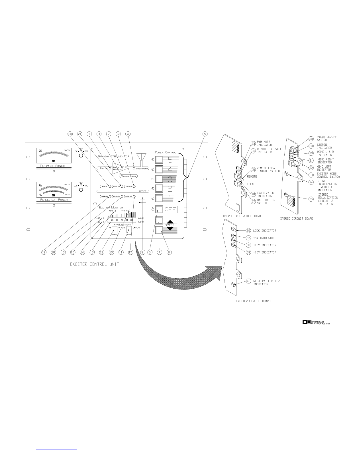
597-1114-23
FIGURE 3-2. ECU CONTROLS AND INDICATORS
(3-7/3-8)
COPYRIGHT 1999 BROADCAST ELECTRONICS, INC
Page 58

TABLE 3-2. ECU CONTROLS AND INDICATORS
(Sheet 5 of 6)
INDEX
NO. NOMENCLATURE FUNCTION
16 L/L+R Display Illuminates to indicate the autorange feature is
X10 Indicator enabled to expand the L/L+R display by 10 to provide
the resolution required for low level audio monitoring.
17 OVERTEMP Indicator Illuminates to indicate when the transmitter
operating temperature exceeds 70° C (158° F).
18 FOLDBACK Indicator Illuminates to indicate when the transmitter is in a
foldback condition. Foldback is when the transmitter
output power is automatically reduced in response to
one of the following fault conditions: 1) high reflected
power, 2) high forward power, 3) high temperature, or
4) detection of a lightning potential.
19 INTERLOCK Illuminates to indicate the internal interlock, external
Indicator interlock, and the remote fail-safe are closed. The
remote control fail-safe must be closed only when the
transmitter is configured for remote control operation.
20 REMOTE Indicator Illuminates to indicate transmitter remote control
operations are enabled.
21 CONFLICT Indicator Illuminates to indicate an incorrect power level is
selected for operation into the antenna connected to
the transmitter.
22 LIGHTNING Indicator In the AM-2.5E, illuminates to indicate a 1500 volt or
greater potential is present at the transmitter output.
In the AM-5E, illuminates to indicate a 2100 volt or
greater potential is present at the transmitter output.
23 PWM Mute Indicator Illuminates to indicate the power control PWM signal
is muted in response to a fault such as lightning, an
exciter fault, a reflected power emergency, an open
remote control fail-safe, or an external transmitter
mute.
24 Remote Fail-safe Illuminates to indicate the remote control unit is
Indicator enabled.
25 Remote/Local Controls the transmitter remote control operations.
Switch When the switch is operated to remote, remote control
operations are enabled. When the switch is operated
to local, remote control operations are disabled.
3-9
Page 59

TABLE 3-2. ECU CONTROLS AND INDICATORS
(Sheet 6 of 6)
INDEX
NO. NOMENCLATURE FUNCTION
26 Battery OK Indicator When the battery test switch is depressed, the indi-
cator will: 1) illuminate to indicate the battery is
operational or 2) not illuminate to indicate the battery
is to be replaced.
27 Battery Test Switch When depressed, evaluates the controller battery
status. The status is displayed by the battery OK
indicator.
28 Pilot On/Off Switch Enables and disables the stereo pilot signal.
29 Stereo Indicator Illuminates to indicate the exciter is configured to the
stereo mode.
30 Mono L+R Indicator Illuminates to indicate the exciter is configured to the
mono L+R mode.
31 Mono Right Indicator Illuminates to indicate the exciter is configured to the
mono right mode.
32 Mono Left Indicator Illuminates to indicate the exciter is configured to the
mono left mode.
33 Exciter Mode Configures the exciter for stereo, mono L+R, mono
Control Switch left, or mono right operation. The switch is designed
to configure the exciter to a different mode of operation each time the switch is depressed. The switch
will advance to a mode of operation in the following
order: 1) mono left, 2) mono right, 3) mono L+R, and
4) stereo.
34 Stereo Equalization 1 Illuminates to indicate the exciter stereo equalization
Indicator 1 circuit is active.
35 Stereo Equalization 2 Illuminates to indicate the exciter stereo equalization
Indicator 2 circuit is active.
36 Lock Indicator Illuminates to indicate the exciter is locked to the
programmed carrier frequency.
37 Exciter +5V Indicator Illuminates to indicate the ECU +5V supply is
operational.
38 Exciter +15V Indicator Illuminates to indicate the ECU +15V supply is
operational.
39 Exciter -15V Indicator Illuminates to indicate the ECU -15V supply is
operational.
40 Negative Limiter Illuminates to indicate the negative limiter circuit is
Indicator enabled. Factory adjusted to illuminate at
approximately 94% negative modulation.
3-10
Page 60
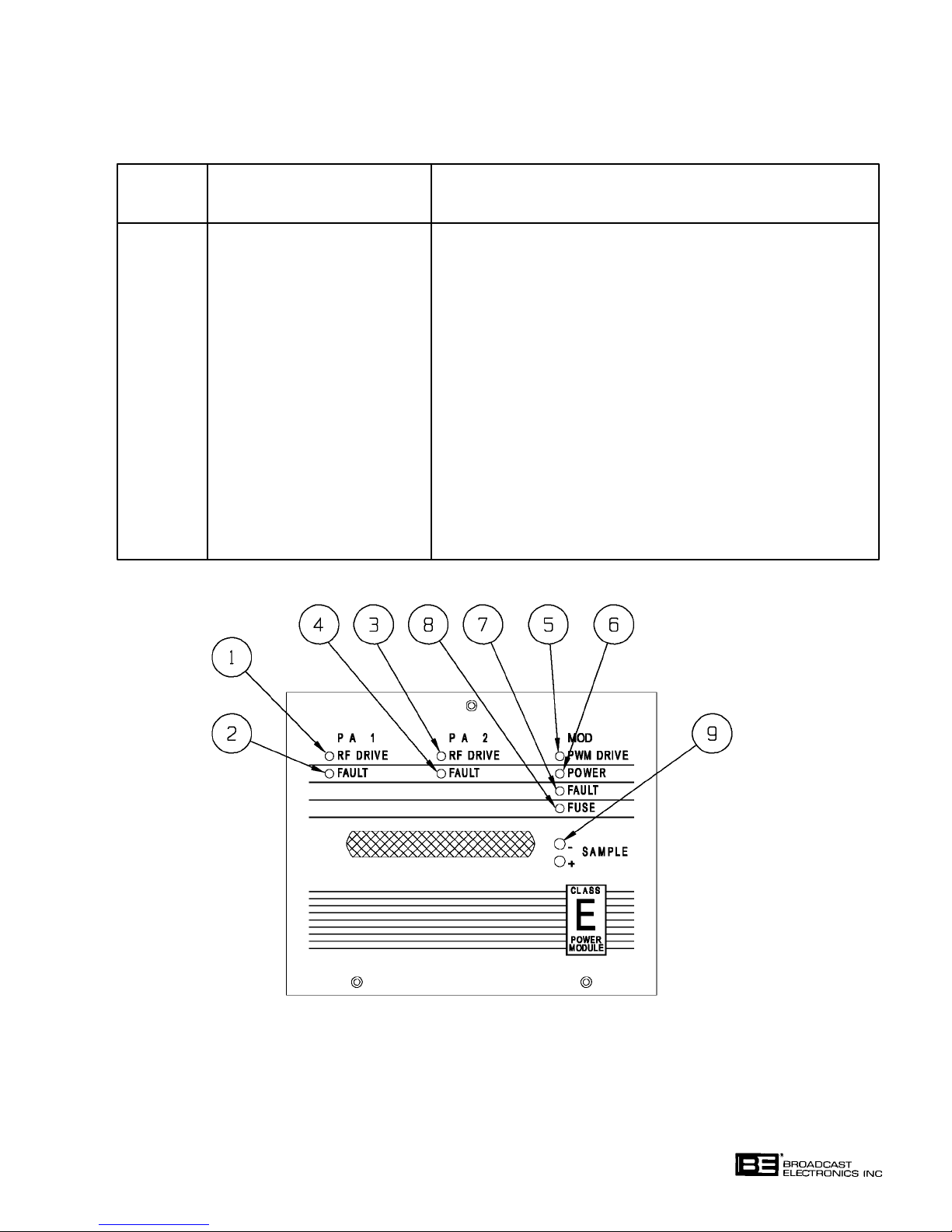
TABLE 3-3. POWER MODULE CONTROLS AND INDICATORS
(Sheet 1 of 2)
INDEX
NO. NOMENCLATURE FUNCTION
1 PA 1 RF DRIVE Illuminates to indicate RF drive is present at
Indicator power amplifier 1.
2 PA 1 FAULT Illuminates to indicate a fault has occurred
Indicator in power amplifier 1.
3 PA 2 RF DRIVE Illuminates to indicate RF drive is present at
Indicator power amplifier 2.
4 PA 2 FAULT Illuminates to indicate a fault has occurred in
Indicator power amplifier 2.
5 MOD PWM DRIVE Illuminates to indicate the exciter PWM drive
Indicator is present at the modulator circuit board.
6 MOD POWER Illuminates to indicate dc power is present at the
Indicator modulator circuit board.
FIGURE 3-3. POWER MODULE CONTROLS AND INDICATORS
COPYRIGHT 1999 BROADCAST ELECTRONICS, INC
597-1112-31
3-11
Page 61
TABLE 3-3. POWER MODULE CONTROLS AND INDICATORS
(Sheet 2 of 2)
INDEX
NO. NOMENCLATURE FUNCTION
7 MOD FAULT Illuminates to indicate a fault has occurred in the
Indicator modulator circuit board.
8 MOD FUSE Illuminates to indicate the modulator circuit
Indicator board fuse has blown.
9 MOD SAMPLE Provides a dc voltage sample of the modulator circuit
board output. In the AM-2.5E, the sample will be
equal to approximately 5.6 volts dc at 2.5 kW (refer to
factory test data sheets). In the AM-5E, the sample
will be equal to approximately 5.6 volts dc at 5 kW
(refer to factory test data sheets).
3-5. OPERATION.
CAUTION
WHEN AC POWER IS APPLIED TO THE TRANSMIT
TER AND THE RF DRIVE AND PWM DRIVE INDICA
CAUTION
TORS ON RF POWER MODULES IN A POWER BLOCK
ARE EXTINGUISHED, THE RF POWER MODULES
MUST BE REMOVED FROM THE TRANSMITTER
CHASSIS TO PREVENT DAMAGE TO THE MODULES.
NOTE
ENSURE THE TRANSMITTER IS COMPLETELY
INSTALLED PRIOR TO PERFORMING THE FOLLOW
NOTE
3-6. TURN-ON.
3-7. Operate the transmitter to ON by performing the following procedure.
3-8. Ensure the transmitter rear-panel ac on/off switch is operated to ON. The ECU and RF
power module front-panel indicators will illuminate.
3-9. Observe the ECU and RF power module indicators. Ensure normal operating conditions
are displayed by all indicators. If an indicator displays a fault condition, operate the ac
power switch to off and refer to SECTION V, MAINTENANCE to locate the problem.
3-10. Select an output power level by depressing the desired power level switch/indicator. The
following events will occur:
ING PROCEDURES.
1. The power level switch indicator will illuminate.
2. The transmitter flushing fans will begin operation.
3. The transmitter output power will be displayed on the FORWARD and
REFLECTED power meters.
3-12
Page 62

3-11. Operate the FORWARD and REFLECTED power meters to observe the transmitter for
ward and reflected power indications.
3-12. Adjust the transmitter output power if required by performing the POWER ADJUST
procedure presented in the following text.
3-13. If remote control operation is desired, operate the local/remote switch on the controller cir
cuit board to remote. This will enable both local and remote operation.
3-14.
3-15. Operate the transmitter to OFF by depressing the OFF switch/indicator to illuminate the
3-16. METERING.
3-17. FORWARD POWER. The forward power meter presents forward power indications. To
3-18.
TURN OFF.
switch/indicator. The transmitter will operate to off.
operate the meter, proceed as follows:
1. To monitor low forward power levels, operate the FORWARD POWER meter
switch to LOW. In the AM-2.5E, the LOW scale is from 0 to 300 watts. In the
AM-5E, the LOW scale is from 0 to 1500 watts.
2. To monitor high forward power levels, operate the FORWARD POWER meter
switch to HIGH. In the AM-2.5E, the HIGH scale is from 0 to 3000 watts. In the
AM-5E, the HIGH scale is from 0 to 6000 watts.
3. To configure the FORWARD POWER meter to off, operate FORWARD POWER
meter switch to OFF.
REFLECTED POWER. The reflected power meter presents reflected power and ac input
indications. To operate the meter, proceed as follows:
1. To monitor low reflected power levels, operate the REFLECTED POWER meter
switch to LOW. In the AM-2.5E, the LOW scale is from 0 to 60 watts. In the
AM-5E, the LOW scale is from 0 to 150 watts.
2. To monitor high reflected power levels, operate the REFLECTED POWER meter
switch to HIGH. In the AM-2.5E, the HIGH scale is from 0 to 300 watts. In the
AM-5E, the HIGH scale is from 0 to 600 watts.
3. To monitor the ac input voltage, operate the REFLECTED POWER meter
switch to VAC.
3-19.
3-20. The POWER and switches adjust the transmitter output power. To adjust the trans
POWER ADJUST.
mitter power, proceed as follows:
1. Depress the POWER switch to increase the transmitter output power. Observe
the transmitter output power indications on the FORWARD and REFLECTED
power meters.
The switch will increase power from 10% to 15% of the selected power level.
2. Depress the POWER
the transmitter output power indications on the FORWARD and REFLECTED
power meters.
The switch will decrease power from 10% to 15% of the selected power level.
OR
switch to decrease the transmitter output power. Observe
3-13
Page 63

3-21. MONO/STEREO OPERATION.
3-22. To configure the transmitter for monophonic or stereophonic operation, perform the follow
ing procedures.
3-23.
3-24.
3-25. Mono Operation - Stereo Circuit Board. To configure the transmitter for mono operation
3-26. Mono Operation - No Stereo Circuit Board. In the event of a stereo circuit board failure,
STEREO OPERATION. To configure the transmitter for stereo operations, depress the ex
citer mode control switch to illuminate the stereo indicator on the stereo circuit board. In
addition, the ECU front-panel stereo indicator will illuminate.
MONO OPERATION. The transmitter can be configured to the monophonic mode by:
1) manually selecting the desired mono mode using the stereo circuit board or 2) automati
cally configuring the transmitter by removing the stereo circuit board. To configure the
transmitter for mono operations, proceed as follows:
using the stereo circuit board, depress the exciter mode control switch to illuminate the
mono L+R, mono left, or mono right indicators on the stereo circuit board. In addition, the
ECU front-panel MONO indicator will illuminate.
the transmitter will automatically configure to the monophonic mode when the stereo cir
cuit board is removed from the ECU. To remove the stereo circuit board and configure the
transmitter for monophonic operation, proceed as follows:
CAUTION
TO PREVENT DAMAGE TO THE TRANSMITTER, EN
SURE THE TRANSMITTER PRIMARY POWER IS OPER
CAUTION
ATED TO OFF BEFORE REMOVING THE STEREO CIR
CUIT BOARD.
1. Operate the transmitter primary power to off.
2. Completely remove the stereo circuit board from the ECU. Do not leave the circuit
board in the ECU chassis.
3. Refer to Figure 2-5 in SECTION II, INSTALLATION and ensure the monophonic
audio channel select jumper is configured for the desired audio channel.
4. If required, adjust the single channel level by referring to SECTION II,
INSTALLATION and performing the SINGLE CHANNEL LEVEL procedure.
3-27. PILOT CONTROL.
3-28. The pilot switch on the stereo circuit board controls the pilot tone. Operate the pilot switch
to on to enable the pilot tone. Operate the pilot switch to off to disable the pilot tone.
3-29.
3-30. The following text presents procedures for specific exciter monitoring functions. Perform
3-31. MONO/STEREO INDICATIONS. The MONO and STEREO indicators display the oper
3-32.
EXCITER MONITOR OPERATION.
the appropriate procedure for the type of monitor function desired.
ating mode of the exciter. The MONO indicator will illuminate to indicate when the excit
er is configured for mono L+R, mono left, or mono right operation. The STEREO indicator
will illuminate to indicate when the exciter is configured for stereo operation.
INPUT SELECTION. Depress the L/R/L+R/L-R MODE switch/indicator to: 1) illuminate
the L/R indicator to select left and right channel information or 2) illuminate the L+R/L-R
indicator to select L+R and L-R information. The selected parameter will appear on the
EXCITER MONITOR display.
3-14
Page 64

3-33. POLARITY SELECTION. Depress the POLARITY switch/indicator to: 1) illuminate the +
indicator to select positive peak audio or 2) illuminate the - indicator to select negative
peak audio. The selected parameter will appear on the EXCITER MONITOR display.
3-34. X10 AUTORANGE INDICATIONS. The EXCITER MONITOR display is designed with
an autorange function to provide the appropriate resolution for the applied signal level.
The L/L+R display X10 indicator will illuminate to indicate the display is expanded by 10.
The R/L-R display X10 indicator will illuminate to indicate the display is expanded by 10.
3-35.
3-36. The transmitter monitors several parameters for fault conditions. The RESET indicator
FAULT RESET.
will illuminate to indicate a fault when one of the following conditions occur:
1) over-temperature, 2) exciter fault, 3) power supply fault, 4) RF power module fault,
5) high reflected/forward power, 6) reflected power emergency, or 7) lightning. Once the
fault condition is removed, the fault circuitry must be reset. If a power supply fault is en
countered, the transmitter AC power must be disconnected to remove the fault condition
(refer to POWER SUPPLY FAULT RESET in the following text). To reset the fault cir
cuitry, depress the RESET switch. The fault circuitry will be reset.
3-37.
3-38. If a power supply fault is encountered, ac power must be disconnected from the transmitter
3-39.
3-40. The transmitter controller is equipped with an on/off cycle counter circuit. The circuit is
3-41.
3-42. The transmitter is protected from modulation levels above 150% by an over-modulation
3-43.
3-44. The TRANSMITTER MONITOR is designed to present the operating status of: 1) the
POWER SUPPLY FAULT RESET.
to clear the fault. To reset a power supply fault, proceed as follows:
1. Operate the rear-door ac ON/OFF switch to off.
2. Operate the rear-door ac on/off switch to on.
3. Depress the RESET switch.
OVER-CYCLE OFF.
designed to monitor transmitter on/off cycles. If the transmitter is operated on/off seven
times within 15 seconds, the transmitter will automatically operate to OFF. The power
level or OFF switch/indicators will not respond. To operate the transmitter to ON, proceed
as follows:
1. Do not depress any power level switch/indicators or the OFF switch/indicator for
approximately 30 seconds. This allows the circuit to reset.
2. Depress the desired power level switch/indicator.
OVER-MODULATION PWM MUTE.
circuit. If the transmitter modulation increases to a level above 150%, the PWM signal
will be muted. This will mute the output power and prevent damage to the transmitter
power supply modules.
TRANSMITTER MONITOR.
exciter, 2) the RF power modules, 3) the power supply, 4) the antenna, 5) the remote con
trol, 6) antenna conflict conditions, 7) lightning conditions, 8) interlocks, 9) foldback condi
tions, and 10) over-temperature conditions. Use the information presented in Table 3-2 to
determine the status of the transmitter components and operating conditions.
3-45.
3-46. The battery test and battery OK indicator check the ECU battery backup system. To check
BATTERY TEST.
the ECU battery, depress the battery test switch. The battery OK indicator will illuminate
to indicate an acceptable battery voltage. If the battery OK indicator does not illuminate,
replace the battery.
3-15
Page 65

3-47. CONTROLLER PWM MUTE INDICATOR.
3-48. The PWM mute indicator illuminates to indicate when the power control PWM signal is
muted. The power control PWM signal is muted during: 1) lightning conditions, 2) an ex
citer fault, 3) reflected power emergency conditions, 4) an open remote control fail-safe, or
5) a transmitter mute control signal.
3-49.
3-50. The controller remote fail-safe indicator illuminates to indicate the remote control unit is
3-51. EXCITER LOCK INDICATOR.
3-52. The exciter circuit board lock indicator illuminates to indicate when the exciter is locked to
3-53.
3-54. The exciter circuit board +5V, +15V, and -15V indicators display the status of the operating
3-55. STEREO EQUALIZATION INDICATORS.
3-56. The stereo circuit board equalization 1 indicator illuminates to indicate when equalization
3-57. RF POWER MODULE INDICATORS.
3-58. The RF power module indicators are designed to present the operating status of the power
CONTROLLER REMOTE FAIL-SAFE INDICATOR.
enabled. The indicator will extinguish when the remote control unit is disabled.
the programmed carrier frequency. The indicator will extinguish when the exciter is un
locked from the programmed carrier frequency.
EXCITER +5V/+15V/-15V INDICATORS.
potentials from the ECU power supply. The +5V, +15V, and -15V indicators will illuminate
to indicate the +5 volt, +15 volt, and -15 supplies are operational.
circuit 1 is selected. The stereo circuit board equalization 2 indicator illuminates to indi
cate when equalization circuit 2 is selected.
amplifier circuit boards and the modulator circuit board. Use the information presented in
Table 3-3 to determine the status of the power amplifier circuit boards and the modulator
circuit board.
3-59.
3-60. On AM-5E models, the power supply indicators on the transmitter lower front-panel are
3-61.
3-62. The exciter circuit board negative limiter indicator displays the status of the exciter nega
3-63. HIGH/LOW AC LINE CONDITIONS.
3-64. The transmitter is equipped with an ac line monitor. The monitor will deenergize the
POWER SUPPLY INDICATORS.
designed to present the operating status of the power supply circuit boards. The AM-5E
transmitter is equipped with power supply 1-2 and 3-4. The indicators illuminate to indi
cate a failure in a power supply.
EXCITER NEGATIVE LIMITER INDICATOR.
tive limiter circuit. The indicator will illuminate to indicate the negative limiter circuit is
enabled. The indicator is factory adjusted to illuminate at approximately 94% negative
modulation.
transmitter in the event the ac power line is below 190 Volts or above 260 Volts. If this
condition occurs: 1) the transmitter output power will be disabled and 2) a no fault or
emergency condition will be generated. The transmitter will re-energize when the high/
low ac line condition is removed.
3-16
Page 66

SECTION IV
THEORY OF OPERATION
4-1. INTRODUCTION.
4-2. This section presents the theory of operation for the Broadcast Electronics
AM-2.5E/AM-5E transmitters.
4-3. The following text presents the AM-2.5E/AM-5E transmitter overall theory of operation.
The transmitter is divided into modular components for the discussion. The modular
components consist of the: 1) exciter/control unit (ECU), 2) output network, 3) RF power
module, 4) RF combiner, and 5) power supply. The ECU, RF power module, and power
supply are presented in further detail by the publication sections at the end of this
manual.
4-4. Figures 4-1 and 4-2 present the AM-2.5E and AM-5E block diagrams. Figure 4-1
presents the AM-2.5E block diagram. Refer to Figure 4-1 and the AM-2.5E overall
schematic diagram in SECTION VII as required for the following discussion. Figure 4-2
presents the AM-5E block diagram. Refer to Figure 4-2 and the AM-5E overall
schematic diagram in SECTION VII as required for the following discussion.
4-5.
4-6. ECU.
4-7. GENERAL. The transmitter ECU (exciter/control unit) is a modular assembly containing
4-8.
4-9. The stereo circuit board is equipped with four modes of operation: 1) mono left, 2) mono
4-10. The stereo circuit board operates in association with the ECU exciter circuit board to
FUNCTIONAL DESCRIPTION.
plug-in stereo, exciter, controller, and extender circuit board assemblies. A forward
power meter is provided to monitor the transmitter forward output power. A reflected
power/primary ac power meter provides reflected power and primary ac voltage
indications. The ECU switch and display circuitry is contained on switch and display
circuit boards. Power for the ECU is provided by a modular switching power supply unit.
STEREO CIRCUIT BOARD. The ECU stereo circuit board consists of C-QUAM AM stereo
circuitry. C-QUAM AM stereo is a mode of AM stereo transmission utilizing amplitude
modulated (L+R) information and independently quadrature modulated stereo (L-R)
information. The results produce a stereo transmission system compatible with mono
receivers.
right, 3) mono L+R, and 4) stereo. Configuring the circuit board to monophonic operation
is accomplished by: 1) operating the circuit board to the mono left, mono right, or mono
L+R mode or 2) removing the stereo circuit board. The circuit board is equipped with two
equalization circuits. The circuits allow the transmitter to be configured for two different
antenna patterns such as for a day pattern and a night pattern.
provide RF drive to the RF power modules. The stereo circuit board receives left and
right channel audio and an unmodulated TTL level RF signal at 4 times the carrier
frequency from the exciter circuit board. The stereo circuit board outputs a TTL level RF
signal to the exciter circuit board.
4-11. EXCITER CIRCUIT BOARD. The ECU exciter circuit board is a modular plug-in exciter
assembly. The circuit board operates in association with the stereo circuit board to
produce a C-QUAM AM stereo RF output. Instrumentation amplifiers provide balanced
left and right channel transformerless audio inputs.
4-1
Page 67

4-12. The exciter circuit board generates: 1) a PWM (pulse-width-modulation) signal and 2) an
RF carrier frequency signal. The 122 kHz to 135 kHz PWM signal is routed for
application to the modulator circuit boards in the RF power modules. The RF carrier
frequency signal is applied to the power amplifier circuit boards in the RF power modules.
The exciter carrier frequency is established by a digital frequency synthesizer. The
synthesizer is a phase-locked-loop circuit which provides extremely accurate and reliable
carrier frequency operation.
4-13.
4-14. The controller circuit board is designed with two interlock circuits. A transmitter
4-15. The transmitter power is controlled by a power control circuit. The circuit allows the
4-16. Several monitoring and display circuits provide information on transmitter operating
4-17. Additional display circuits include: 1) remote, 2) conflict, 3) lightning, 4) interlock,
CONTROLLER CIRCUIT BOARD. All transmitter control operations are directed by the
ECU controller circuit board. The controller circuit board is designed with CMOS control
and monitoring circuitry.
external interlock is provided such as for a test load. An antenna interlock circuit is
provided to prevent the transmitter from operating into an incorrect antenna.
transmitter to be operated at five power levels. A power trim circuit allows the
transmitter power to be increased or decreased as required. A high reflected power
detection circuit, a high forward power detection circuit, and a high temperature
detection circuit operate in association with the power control circuit to foldback the
transmitter power during high reflected power, high forward power, and high
temperature conditions. In addition, a lightning detector circuit is provided to mute the
transmitter when lightning is present at the antenna.
conditions. An RF power module status circuit displays: 1) if a module is removed for
maintenance or 2) if a power module fault has occurred. A power supply status circuit
displays: 1) if a power supply circuit board is removed for maintenance or 2) if a power
supply fault has occurred. An exciter status circuit indicates if a fault has occurred in the
exciter. An antenna status circuit displays: 1) 1.2 : 1 VSWR conditions, 2) high reflected
power conditions, and 3) emergency reflected power conditions.
5) over-temperature, and 6) reset. A remote indicator displays the status of the remote
control system. A conflict indicator illuminates to indicate an incorrect power level is
selected for operation into an antenna. A lightning indicator illuminates to indicate the
presence of lightning at the transmitter output. An interlock indicator displays the status
of the internal and external interlock. An over-temperature indicator illuminates to
indicate a transmitter temperature greater than 70 degrees C. A reset indicator
illuminates to indicate a transmitter fault has occurred. Transmitter faults include:
1) exciter failure, 2) power supply failure, 3) RF power module failure, 4) high reflected
power conditions, 5) reflected power emergency conditions, 6) over-temperature
conditions, 7) lightning conditions, and 8) 1.2:1 VSWR conditions.
4-18.
4-19. RF POWER MODULE.
4-20. An RF power module is a plug-in assembly containing two RF amplifier circuit boards
POWER SUPPLY. DC operating potentials for the ECU assembly is provided by a modular
switching power supply unit. The unit provides +5V, +15V, and -15V dc operating
potentials for the ECU circuit boards. +5V, +15V, and -15V indicators are provided on the
exciter circuit board.
and a modulator circuit board. Each RF power module is designed to produce 1375 watts
of RF power. Two RF power modules are contained in a power block. The AM-2.5E
transmitter is equipped with 1 power block. The AM-5E transmitter is equipped with 2
power blocks.
4-2
Page 68
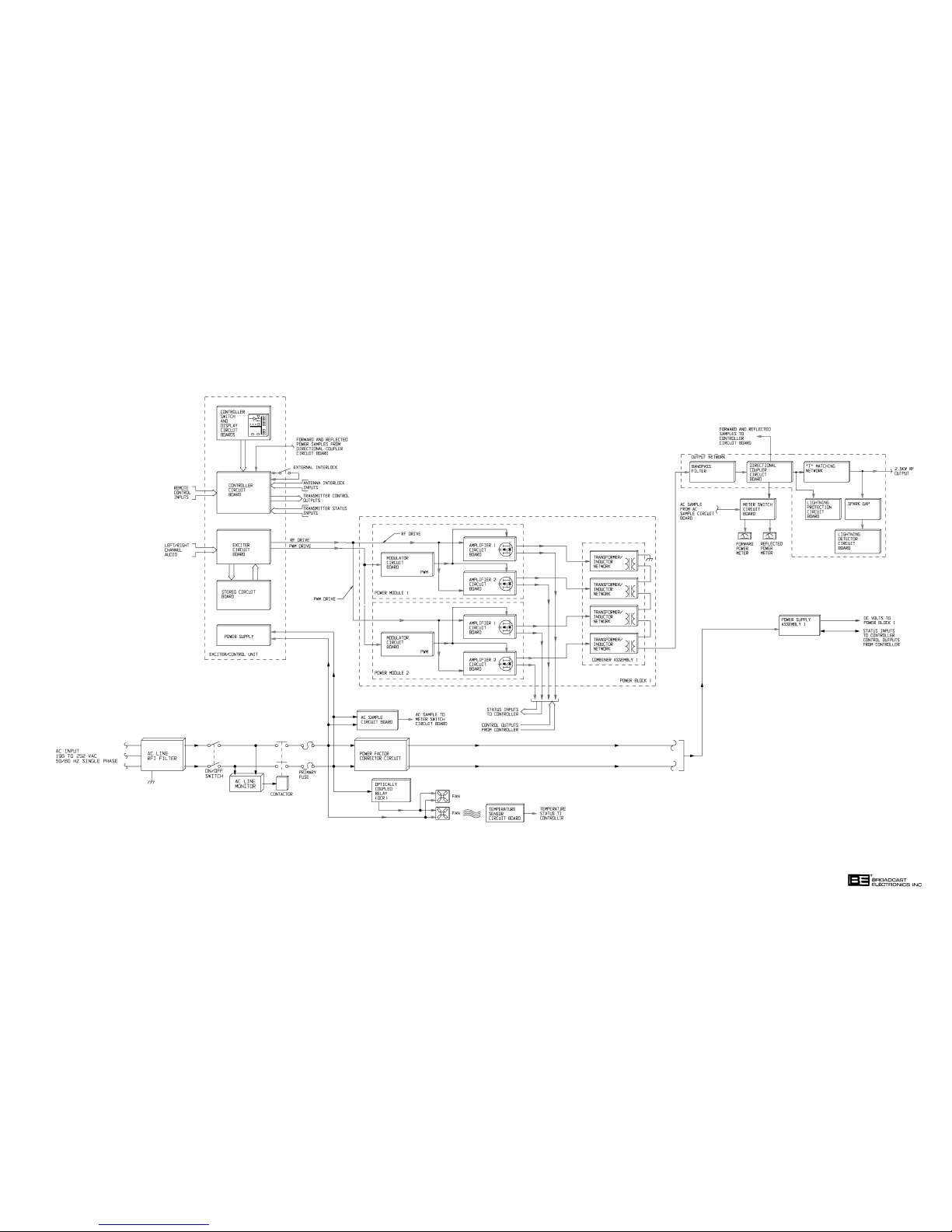
597-1114-5
FIGURE 4-1. AM-2.5E BLOCK DIAGRAM
(4-3/4-4)
COPYRIGHT 1999 BROADCAST ELECTRONICS, INC
Page 69
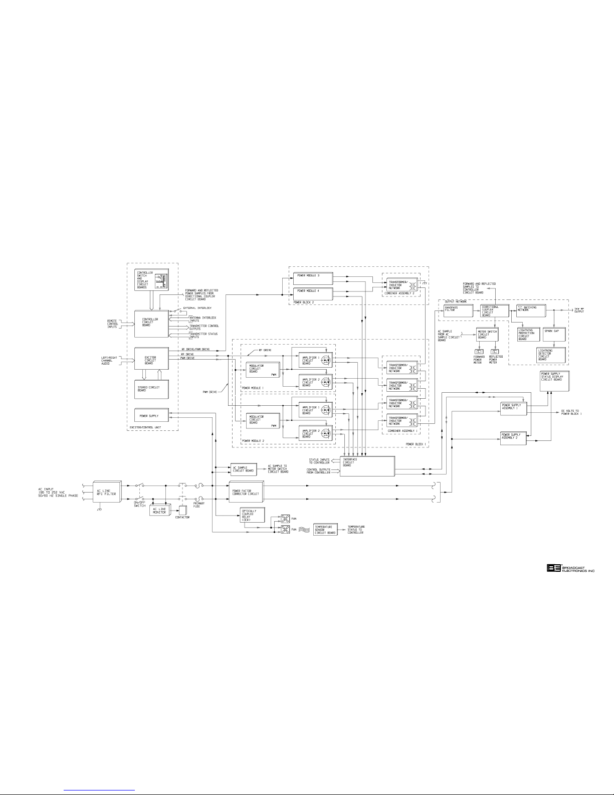
597-1114-4
FIGURE 4-2. AM-5E BLOCK DIAGRAM
(4-5/4-6)
COPYRIGHT 1999 BROADCAST ELECTRONICS, INC
Page 70

4-21. The modular design of the RF power modules allow the modules to be removed from the
transmitter for maintenance. The remaining power modules will provide power to
maintain on-air operation.
4-22. The PWM signal from the exciter circuit board is applied to the modulator circuit board.
The modulator circuit board is designed to amplify and convert the PWM signal to a dc
voltage which varies at an audio rate. The output of the modulator circuit board is
applied to the RF amplifier circuit boards. Four indicator circuits monitor and display the
status of the: 1) PWM drive signal, 2) B+ dc supply, 3) modulator fault conditions, and
4) blown fuse conditions.
4-23. The RF amplifier circuit boards are designed with Class E amplifier technology and
MOSFET power transistors. The circuit board operates from: 1) the varying dc voltage
from the modulator circuit board and 2) the RF drive signal from the exciter circuit board.
The RF drive signal from the exciter circuit board and the varying dc voltage from the
modulator are applied to a push-pull power MOSFET transistor amplifier circuit. The
amplifier circuit is designed to output approximately 687.5 watts of RF power. A fault
detection circuit monitors amplifier operation for fault conditions.
4-24.
4-25. Power from each RF amplifier circuit board is applied to a star combiner network. The
4-26. In addition to combining the RF power from the RF power modules, the combiner design
4-27.
4-28. The output network is a modular assembly designed to match the transmitter impedance
4-29. The bandpass filter is an eight element LC filter designed to attenuate all harmonic
RF COMBINER.
combiner components are located on the rear panel of each power block. The star
combiner network consists of individual transformer and inductor networks for each
amplifier circuit board. The combiner accepts RF power from each RF power module to
produce the rated RF output power.
allows one or more RF power modules to be removed from the transmitter for
maintenance. The remaining RF power modules will continue to operate to maintain
on-air operation. This is accomplished without the use of dummy modules or bypass
switches.
OUTPUT NETWORK.
to the antenna. The assembly consists of a: 1) bandpass filter, 2) directional coupler
circuit board, 3) T-matching network, 4) lightning protection circuit board, and 5) a
lightning detection circuit board.
frequencies to FCC, DOC, and CCIR levels. The directional coupler circuit board consists
of a circuit designed to sample the transmitter RF output. The circuit board generates
both forward and reflected power samples for application to the controller circuit board.
The T" matching network consists of an LC network. The network is designed to match
the transmitter impedance to the antenna.
4-30. A lightning protection circuit board is provided to protect the transmitter circuitry from
direct lightning potentials. The circuit protects the transmitter by shunting lightning
potentials to ground. The lightning detector circuit board is designed to mute the
transmitter RF output during the presence of a lightning potential. The lightning
detector circuit board is controlled by a spark gap. The circuit will respond to potentials
of 1500 volts in AM-2.5E models and 2100 volts in AM-5E models. This prevents the
transmitter from muting during near-by lightning activity.
4-7
Page 71

4-31. POWER SUPPLY.
4-32. A single phase source of 196 to 252 volts ac 50/60 Hz is required to operate the
transmitter. The power source is routed through an RFI filter to prevent the coupling of
RFI components into or out-of the transmitter. A rear-door ac on/off switch provides ac
power control and disconnects all ac power to the transmitter when the door is opened.
The ac line is monitored for high/low conditions by an ac line voltage monitor. The
transmitter primary ac power will be interrupted if the ac line is above 260 volts or below
195 volts. Primary fuses protect the transmitter from over-current conditions. A power
factor corrector circuit modifies the ac line impedance to provide a power factor of
approximately 0.9.
4-33. The ac line voltage is sampled at the ac sample circuit board. The sample circuit board
provides an ac line voltage sample for application to the meter switch circuit board.
4-34.
POWER SUPPLY CIRCUIT BOARD. DC operating potentials for the RF power modules
are provided by power supply circuit boards. One power supply circuit board provides dc
operating potentials for one power block. The AM-2.5E transmitter is equipped with 1
power supply circuit board. The AM-5E transmitter is equipped with 2 power supply
circuit boards.
4-35. The power supply circuit board consists of a: 1) switching power supply circuit,
2) conventional bridge rectifier circuit, 3) fault detection circuit. The switching power
supply circuit operates directly from the ac power source. No primary ac power
transformer is included in the circuit. An SCR controlled bridge rectifier circuit and a
switching regulator circuit converts ac potentials to dc potentials at a desired voltage.
Control of the dc output voltage is provided by a power control PWM signal from the
controller.
4-36. A transformer with five secondary windings provide low-voltage ac potentials to five
full-wave bridge rectifiers circuits. The circuits provide dc operating potentials for the
power supply circuit board and RF power module circuitry.
4-37. The power supply design provides the RF power modules with a constant and stable dc
operating supply by not responding to fluctuations or surges in the ac line voltage. The
supply will produce a constant dc voltage during high/low ac line voltage or surge
conditions.
4-38. The switching power supply output voltage is controlled by a power control PWM signal
from the controller circuit board. Current reduction at turn-on is controlled by a
soft-start circuit. The circuit is designed to generate start pulses synchronized to the ac
line phase to slowly bias the SCR bridge rectifier circuit on during initial turn-on
operations. The switching regulator circuitry is monitored for proper operation by an
overvoltage and loss-of-PWM signal circuitry. The switching regulator operation is
performed by IGBT (insulated-gate-bi-polar-transistors) transistors. The IGBTs are
designed to provide extremely reliable and efficient operation.
4-8
Page 72

4-39. METERING.
4-40. The transmitter metering consists of the forward power meter, reflected power/primary ac
input voltage meter, and the exciter modulation meter. Forward power information is
presented on the forward power meter. Reflected power/primary ac input voltage
information is presented on the reflected power/primary ac input voltage meter. The
meters are controlled by three-position switches. Forward and reflected power samples
for the metering circuitry are provided by the directional coupler circuit board. An ac
sample for the reflected power/primary ac input voltage meter is provided by an ac sample
circuit board.
4-41. Monitoring of exciter operations is provided by the exciter modulation monitor. Two 30
segment multi-color bar graph displays present L/L+R and R/L-R information. A X10
mode allows the monitoring of low level signals such as the pilot tone.
4-42.
4-43. The AM-2.5E/AM-5E transmitters are equipped with 2 cooling fans. The fans are
4-44. INTERFACE CIRCUIT BOARD (AM-5E ONLY).
4-45. On AM-5E models, communication between the controller, RF power modules, and the
4-46.
4-47. POWER SUPPLIES.
4-48. The AM-2.5E/AM-5E transmitters require a 196V to 252V ac single phase power source
COOLING FANS.
controlled by an optically-coupled-relay. In the fans provide 500 CFM of cooling air for
the transmitter. A temperature sensor circuit board monitors the transmitter air
temperature and provides status information to the controller.
power supply circuit boards is provided by an interface circuit board. The circuit board:
1) routes status information from the RF power modules and power supply circuit boards
to the controller and 2) routes control signals from the controller to the RF power modules
and the power supply circuit boards.
DETAILED DESCRIPTION.
(refer to Figure 4-3). The following text presents ac power source required for each
transmitter.
TRANSMITTER AC POWER SOURCE
AM-2.5E 196V to 252V ac 50/60 Hz single phase at 75 Amperes.
AM-5E 196V to 252V ac 50/60 Hz single phase at 125 Amperes.
4-49. AC INPUT CIRCUITRY.
4-50. When the transmitter fused disconnect is closed, single phase ac power is routed through
an RFI filter to rear-door ac input switch S1. The filter prevents the coupling of RFI
components into or out-of the transmitter. S1 is the transmitter primary ac power safety
device. S1 disconnects primary ac power when the transmitter rear door is opened.
4-51. The ac line is monitored for high/low conditions by an ac line voltage monitor. The
monitor controls ac power contactor K2. The transmitter primary ac power will be
interrupted if the ac line is above 260 volts or below 190 volts. Overload protection for the
transmitter is provided by fuses F1 and F2.
4-9
Page 73

4-52. A power factor corrector circuit consisting of inductors L3/L4 and capacitor C1 modifies
the ac line impedance to provide a power factor of approximately 0.9. C1 is switched into
the circuit during soft-start by the power factor corrector relay circuit board. The relay
circuit board is controlled by a circuit on the power supply circuit board.
Metal-Oxide-Varistors MOV1, MOV2, and MOV3 protect the transmitter power supply
circuitry from ac line voltage surge potentials. AC power from the MOVs is applied to
the following circuits: 1) the ECU power supply assembly, 2) the transmitter flushing
fans, 3) low voltage power supply transformer T1, 4) the power supply circuit board, and
5) the ac sample circuit board.
4-53.
4-54. The ECU power supply is a 40W modular switching power supply unit. The power supply
4-55. The power supply for the ECU controller circuit board is backed-up by a 9V battery.
4-56. The battery back-up system requires a standard 9V battery. The battery will maintain
4-57.
4-58. Cooling air for the transmitter circuitry is provided by flushing fans B1 and B2. Control
4-59. The flushing fans are controlled by a signal from the ECU controller circuit board. When
ECU POWER SUPPLY ASSEMBLY.
assembly provides regulated +5V, +15V, and -15V operating potentials for the ECU circuit
boards.
During an ac power failure, the battery will maintain the transmitter operating
configuration stored in the controller logic circuitry. Once power is returned to the
transmitter, the transmitter will automatically resume operation in the configuration
appearing prior to the ac failure. If an extended ac power failure occurs, the transmitter
will be operated to off by an ac loss/auto shutdown circuit.
the controller logic for several months. Replace the battery approximately once a year to
ensure proper transmitter operation during ac power failure conditions.
TRANSMITTER FLUSHING FANS.
of the fans is provided by optically-coupled-relay (OCR) K1.
a power level switch/indicator is depressed, the controller circuit board will enable
optically-coupled relay (OCR) K1 to energize the fans. The fans will operate during
transmitter operation.
4-60.
4-61. Low-voltage operating potentials for the transmitter power supply circuit board and RF
4-62.
4-63. Low and high voltage dc operating potentials for the RF power modules are provided by
4-64. The power supply circuit board is equipped with: 1) a switching power supply circuit
LOW-VOLTAGE POWER SUPPLY TRANSFORMER.
power modules are provided by ac power transformer T1. Transformer T1 consists of:
1) one primary winding and 2) five secondary windings. The secondary windings provide
low-voltage ac potentials for application to five rectifier circuits on the power supply
circuit board. The circuitry provides dc operating potentials for the power supply and the
RF power modules.
POWER SUPPLY CIRCUIT BOARD.
the power supply circuit board. The AM-2.5E is equipped with 1 power supply circuit
board. The AM-5E is equipped with 2 power supply circuit boards. Each power supply
circuit board provides dc operating potentials for two RF power modules.
designed to produce high-voltage operating potentials and 2) conventional rectifier
circuitry designed to produce low-voltage operating potentials. The following text
describes the circuitry.
4-10
Page 74
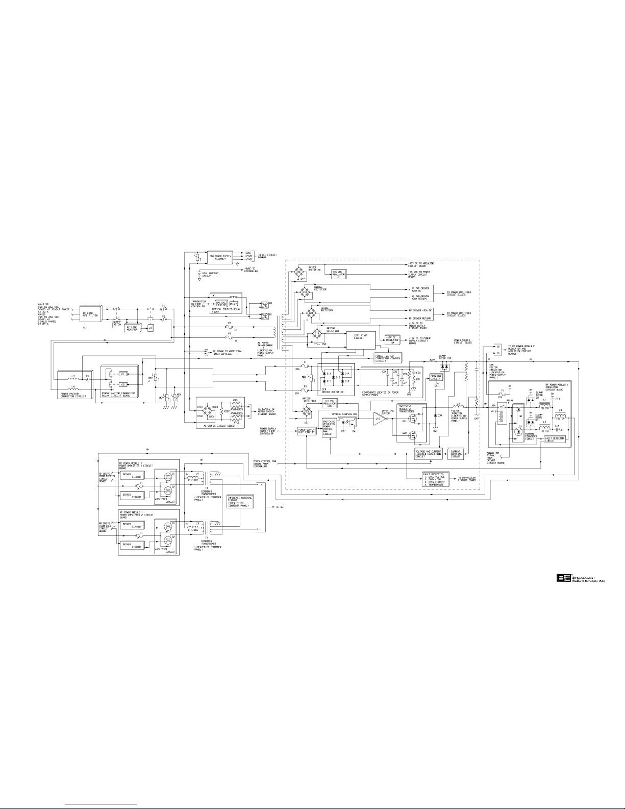
597-1114-6
FIGURE 4-3.
AM-2.5E/AM-5E POWER SUPPLY
SIMPLIFIED SCHEMATIC
(4-11/4-12)
COPYRIGHT 1999 BROADCAST ELECTRONICS, INC
Page 75

4-65. CONVENTIONAL RECTIFIER CIRCUITRY. +30V and +20V dc operating potentials for the
RF power modules are provided by four conventional rectifier circuits. AC power from a
winding of ac power transformer T1 is applied to bridge rectifier D9. D9 rectifies the ac
potential into an unregulated +20 volt ac supply for application to: 1) the modulator
circuit board and 2) to regulator U3. U3 is a +15 volt dc regulator. The output of U3
routed for application to the components on the power supply circuit board.
4-66. AC power from a second winding of transformer T1 is applied to bridge rectifier D10. D10
rectifies the ac potential into an unregulated +20V dc supply for application to the RF
power module power amplifier circuit boards. AC power from a third winding of power
transformer T1 is applied to bridge rectifier D11. D11 rectifies the ac potential into an
unregulated +30V dc supply for application to the RF power module power amplifier
circuit boards. AC power from a fourth winding of power transformer T1 is applied to
bridge rectifier D12. D12 rectifies the ac potential into an unregulated +15V dc supply for
application to: 1) the power supply circuit board and 2) regulator U4. U4 is a +12 volt dc
regulator. The output of U4 routed for application to the components on the power supply
circuit board.
4-67. An ac sample from a winding of T1 is also routed to a soft-start circuit. The soft-start
circuit is designed to generate control pulses synchronized with the ac line phase. A
complete description of the soft-start circuit is presented in Rectifier/Soft-Start Circuit
(refer to the following text).
4-68.
SWITCHING POWER SUPPLY CIRCUIT. AC power from the power factor corrector
circuitry is applied to fuses F1 and F2 on the power supply circuit board. The fuses
protects the power supply circuitry from overload conditions. Metal-Oxide-Varistor
MOV1 prevents damage to the switching power supply circuit from ac line voltage surge
potentials.
4-69. Rectifier/Soft-Start Circuit. The ac line is full-wave rectified by an isolated SCR
controlled bridge rectifier circuit. The SCR bridge rectifier consists of diodes D15 through
D17 and SCRs D13 and D14. The rectifier is controlled by a soft-start circuit. The
soft-start circuit is designed to: 1) determine when the ac line waveform crosses the 0
volt axis and 2) generate short duration pulses in synchronization with the ac line 0 volt
crossings. The pulses are amplified and applied to the gates of the rectifier circuit SCR
components to slowly bias the components on during initial start operations. This
operation eliminates the component stress at power-on by limiting the supply in-rush
current. The rectifier will output an unregulated and unfiltered dc supply at
approximately 300V to an inductor and capacitor filter network.
4-70. The output of the rectifier circuit is applied to afilter consisting of capacitors C24 through
C27. The output of the LC filter generates a 300V main operating supply for the RF
power modules. The positive leg of the dc supply is the common for the dc voltages
contained in the switching regulator circuitry and the RF power modules. The negative
leg of the supply is regulated and controlled to generate the required operating potentials
for the RF power modules.
4-71. Switching Regulator Circuit. The main operating supply is regulated by a buck-type
switching regulator circuit. The switching regulator circuit generates the negative leg of
the B supply. The regulator circuit consists of: 1) a power supply mute circuit, 2) a
switching regulator power control PWM circuit, 3) optical coupler U17 4) inverting buffer
U19, and 5) switching regulator transistors Q21 and Q22.
4-13
Page 76

4-72. A dc operating supply for optical coupler U17 and buffer U19 is generated by bridge
rectifier D25. D25 full-wave rectifies an ac potential from ac transformer T1 into an
unregulated +20V supply. The supply is applied to +18V regulator U16. U16 outputs a
+18V supply which is further regulated to a 5V operating potential by a resistive divider
and a zener diode. The 5V supply is applied to optical couplers U17 and buffer U19.
4-73. Control of the regulator circuit is provided by the switching regulator power control PWM
circuit, a current sampling circuit, and a voltage and current feedback correction circuit.
Together, the circuits function in a closed-loop to control regulator operation. The
switching regulator power control PWM circuit is designed to produce two out-of-phase
square wave signals with varying duty cycles. The duty cycle is varied in response to the
signal from the correction circuit. The output of the control circuit is applied to optical
coupler U17. U17 provides isolation between two different ground circuits. The output of
the coupler is applied to gate drive inverting buffer U19. The output of U19 is applied to
the gates of IGBT switching regulator transistors Q21 and Q22. Q21 and Q22 are
operated to on for a specific time duration to regulate the output voltage for varying load
conditions.
4-74. The regulator circuit output voltage is directed by a 1 kHz power control PWM signal
from the controller. The signal is applied to the correction circuit on the power supply
circuit board. In addition to the 1 kHz PWM signal, a voltage and current sample from
the regulator output is routed to the voltage and current feedback correction circuit. The
correction circuit responds by evaluating the output samples and the power control signal
and generating a correction voltage. The voltage is applied to the switching regulator
power control PWM circuit to adjust the output of the regulator.
4-75. The output of the transistor switching regulator circuit is applied to filter inductor L2.
Protection of the transistors from switching transients during turn on/off operation is
provided by clamp diode D32. Clamp diode D32 protects the transistors by limiting
positive peak voltages. The output of the regulator circuit is applied to circuitry on RF
power module modulator circuit boards.
4-76.
MODULATOR CIRCUIT BOARD.
4-77. The B- leg from the power supply circuit board is routed to circuitry on the RF power
module modulator circuit board. The B- leg is applied to relay K1 on the modulator
circuit board. K1 is controlled by a fault detector circuit. The relay is designed to
immediately remove the supply from the forward converter circuit during a fault
condition. The output of the relay is applied to the converter circuit.
4-78. Transistors Q1 and Q2 are the switching devices in the forward converter circuit. The
circuit is controlled by the audio PWM signal from the driver circuit board. The circuit
operates by switching the applied B- leg at a 122 kHz to 135 kHz rate. The duty cycle of
the PWM signal is 40% with no modulation. The output of the forward converter circuit
is applied to an LC PWM low-pass filter network. Protection of the transistors from
switching transients is provided by clamp diodes D2 and D3. D2 and D3 limit the positive
peak transients appearing on the output.
4-79. A sample of the modulator circuit output is routed to a fault detector circuit. The circuit
will respond to a fault by: 1) routing a control signal to relay K1 to disconnect the
amplifier circuit from the B- supply and 2) route a control signal to the power supply
circuit board to momentarily mute the power supply. After a short delay, a control signal
is routed to the power supply to enable the supply to provide power to RF module 2.
4-80. The B+ leg of the supply is also routed to the modulator circuit board. The B+ leg is
applied to fuse F1 and is the common for the dc voltages contained in the power supply
circuit board switching regulator circuit and the RF power modules. F1 is provided to
protect clamp diodes D2 and D3 from overcurrent conditions.
4-14
Page 77

4-81. POWER AMPLIFIER CIRCUIT BOARDS.
4-82. The power amplifier circuit board circuitry is configured in a Class E switching amplifier
design. A Class E design is recognized by: 1) the application of the B+ power supply
through an RF choke to combining transformers and 2) the use of only two MOSFET
power transistors in a push-pull configuration per amplifier. The circuitry on each
amplifier circuit board is identical, therefore only amplifier circuit board 1 will be
discussed.
4-83. The dc voltage output of the modulator circuit board is routed to the power amplifier 1
circuitry through fuse F1. F1 protects the amplifier circuitry from over-current
conditions. The supply is applied to a switching amplifier circuit consisting of transistors
Q1 and Q2. The B+ leg of the main dc supply from the power supply circuit board is
applied to Q1 and Q2 through choke L4 to a primary center tap of combiner transformer
T4. RF choke L4: 1) prevents RF signals from entering the dc supply and 2) functions as
the last series inductor for the PWM low-pass filter on the modulator circuit board.
4-84. The amplifier circuit is driven by the RF drive signal from the exciter circuit board. The
RF drive signal consists of a square-wave signal at the carrier frequency. The signal is
amplified prior to application to Q1 and Q2 by a driver circuit.
4-85. The amplifier circuit functions by switching the dc voltage from the modulator circuit
board at an RF rate to produce a monophonic or a C-QUAM AM stereo signal at the
programmed carrier frequency. The signal appears at the primary of combiner
transformer T4. The RF signal is transferred to the secondary of T4 and routed to power
amplifier 2 circuit board combiner transformer T3. The RF output signal from T4 is
combined with the RF output signal from transformer T3 to generate a C-QUAM signal
at approximately 1375 watts of carrier.
4-86.
SEQUENCE OF OPERATION.
4-87. When transmitter switch S1 is closed, ac power is routed to contactor K2 and the ac line
monitor. If the ac power line is between 190 and 260 volts, power from K2 is applied to: 1)
the power factor corrector circuitry, 2) the ECU power supply, 3) fan control relay K1, 4)
low-voltage ac power transformer T1, and 5) the ac sample circuit board. If the ac line
voltage is not between 190 and 260 volts, the ac line monitor will open K2 and deenergize
the transmitter. When ac power is applied to T1, a soft start circuit will detect the ac
waveform. When this occurs, the power factor corrector control circuit will energize the
relays on the power factor corrector circuit board to switch capacitor C1 in the circuit.
This enables the power factor corrector circuitry to change the power factor to
approximately 0.9. In response to the application of ac power with no error conditions,
the following controller and RF power module indicators will illuminate green:
CONTROLLER INDICATORS RF POWER MODULE INDICATORS
1. Exciter 1. PA 1 RF Drive
2. Power Modules 2. PA 2 RF Drive
3. Power Supply 3. PWM Drive
4. Antenna
5. Mono or Stereo (depending on
exciter mode of operation)
6. Exciter Circuit Board: 1) +15V, 2) -15V
3) Lock, and 4) +5V
4-15
Page 78

7. Stereo Circuit Board: 1) Mono L+R/Stereo/
Mono L/Mono R (depending on exciter mode
of operation), 2) Equalization 1 or Equalization 2
(depending on antenna configuration)
4-88. A start sequence is initiated when a power level switch/indicator is depressed. Logic from
the controller will enable optically-coupled-relay K1 to enable the flushing fans.
4-89. Logic from the controller will also enable the SCR controlled bridge rectifier circuit on the
power supply circuit board. The B+ dc potential from the rectifier is applied to the
inductor and capacitor filter networks on the power supply panel. Generation of the Bleg is provided by the IGBT switching regulator circuit.
4-90. Power output of the regulator is controlled by the PWM signal from the controller. The
regulator will increase or decrease power as determined by the PWM signal. The output
of the regulator is routed to the modulator circuit board. The modulator POWER
indicator will illuminate if the B+ supply from the power supply circuit board is present.
The modulated output from the modulator circuit board is routed to the power amplifier 1
and power amplifier 2 circuit board for amplification.
4-91.
RF CIRCUITRY.
4-92. EXCITER CIRCUIT BOARD. Audio for application to the AM-2.5E/AM-5E transmitter is
applied to the exciter circuit board (refer to Figure 4-4). The exciter circuit board is
designed to: 1) process left/right channel or monaural audio to generate a
Pulse-Width-Modulated (PWM) signal at 122 kHz to 135 kHz and 2) generate an RF
signal using a frequency synthesizer, a phase modulator for IPM correction, and an RF
driver network.
4-93. Left channel audio is applied to an RFI filter and a defeatable 10 Hz high-pass filter. The
10 Hz high-pass filter is provided to remove low frequency residual products from specific
audio processing units. Balanced-to-unbalanced signal conversion is provided by an
instrumentation amplifier. The output of the instrumentation amplifier is applied to a
defeatable high frequency boost circuit. The high frequency boost circuit is provided to
increase high frequency response to compensate for a Bessel filter in the PWM modulator.
The output of the high frequency boost circuit is applied to an active PWM filter/equalizer
and a mode switching circuit. The output of the PWM filter is routed for application to
the stereo circuit board.
4-94. The mode switching circuit is designed to select the left or right channel for mono left or
mono right operation. A summing amplifier is provided as a mono support circuit to
increase the gain of the circuit 6 dB during mono operations. The output of the summing
amplifier is applied to a 24 uS delay and limiter circuit. The delay circuit is provided for
stereo equalization. The negative limiter is provided to limit negative modulation from
90% to 100%.
4-95. The output of the 24 uS delay and negative limiter is applied to: 1) a PWM circuit and
2) an IPM comparator and corrector circuit. The PWM circuit is designed to output a
square wave signal in which the duty cycle changes in response to the applied audio level.
The output of the PWM circuit is applied to a PWM driver circuit. The PWM driver
circuit consists of parallel transistor drivers to lower the impedance and improve
reliability.
4-16
Page 79

4-96. The transmitter carrier frequency is generated by digitally programmed frequency
synthesizer circuit. The frequency synthesizer is designed to output: 1) the carrier
frequency to a mono/stereo select circuit, 2) a FcX4 (carrier frequency times four) signal
for application to the stereo circuit board, and 3) a 25 Hz pilot signal for application to the
stereo circuit board. A mono/stereo select circuit functions as an automatic mono/stereo
select switch. If a stereo signal from the internal stereo circuit board or an external
stereo generator is present, the exciter will be configured for stereo operation. If the
stereo signal is not present, the circuit will configure the exciter for mono operation. The
output of the mono/stereo select circuit is applied to the IPM (Incidental Phase
Modulation) signal generator and modulator. The IPM signal generator is designed to
produce a waveform similar to the signal produced by the RF amplifier circuitry. The
IPM generator signal is out-of-phase with the signal generated by the RF power
modules. The signal is applied to a modulator circuit which will generate a phase
compensated RF signal at the carrier frequency. The phase compensation will effectively
cancel the IPM generated in the RF circuitry.
4-97. The output of the IPM circuitry is applied to an RF driver network. The network consists
of a high/low side driver and output drive transistors.
4-98.
4-99. Left channel audio from the exciter circuit board is applied to the left channel
4-100. The output of each equalization circuit is routed to an equalization and mono/stereo select
4-101. The output of the equalization and mono/stereo select circuits is applied to a summing
STEREO CIRCUIT BOARD. Left/right channel audio and an RF signal at FcX4 (carrier
frequency times four) from the exciter circuit board is applied to the stereo circuit board.
The stereo circuit board is designed to generate a TTL level RF signal. The circuit board
contains identical left/right channel and equalization 1/2 circuitry. Therefore, only the
left channel equalization 1 circuit will be discussed.
equalization 1 circuit. The equalization circuit consists of 1) a state variable low-pass
filter, 2) an 8 uS group delay section, and 3) a 4 uS group delay section. The circuit is
designed to equalize frequencies to produce maximum separation.
circuit. The equalization circuit selects equalization 1 or equalization 2 as determined by
the selected antenna pattern. The mono/stereo circuit selects the required signals for
stereo, mono left, mono right, or mono L+R operation.
amplifier network. The network functions as a matrix to generate the L+R and L-R
stereo signals. The output of the summing amplifier network is applied to a digital
switching modulator. The modulator accepts: 1) the L+R and L-R signals and 2) four RF
out-of-phase signals at the carrier frequency. The modulator outputs two signals: 1) an
AM modulated signal containing the L+R information and 2) a double-sidebandsuppressed-carrier signal referenced to a 90 degree carrier. The signals are summed and
amplified at U37 to produce a quadrature signal. The output of U37 is applied to a fourth
order linear phase bandpass filter. The output of the filter is applied to an amplitude
limiter circuit. The limiting operation produces the phase modulation (L-R information)
component of the C-QUAM signal. The output of the limiter circuit is routed to the
exciter circuit board.
4-102.
RF POWER MODULE. The PWM and RF drive signals from the exciter circuit board are
routed to the RF power modules. The RF power modules consist of a modulator circuit
board and two RF amplifier circuit boards.
4-17
Page 80
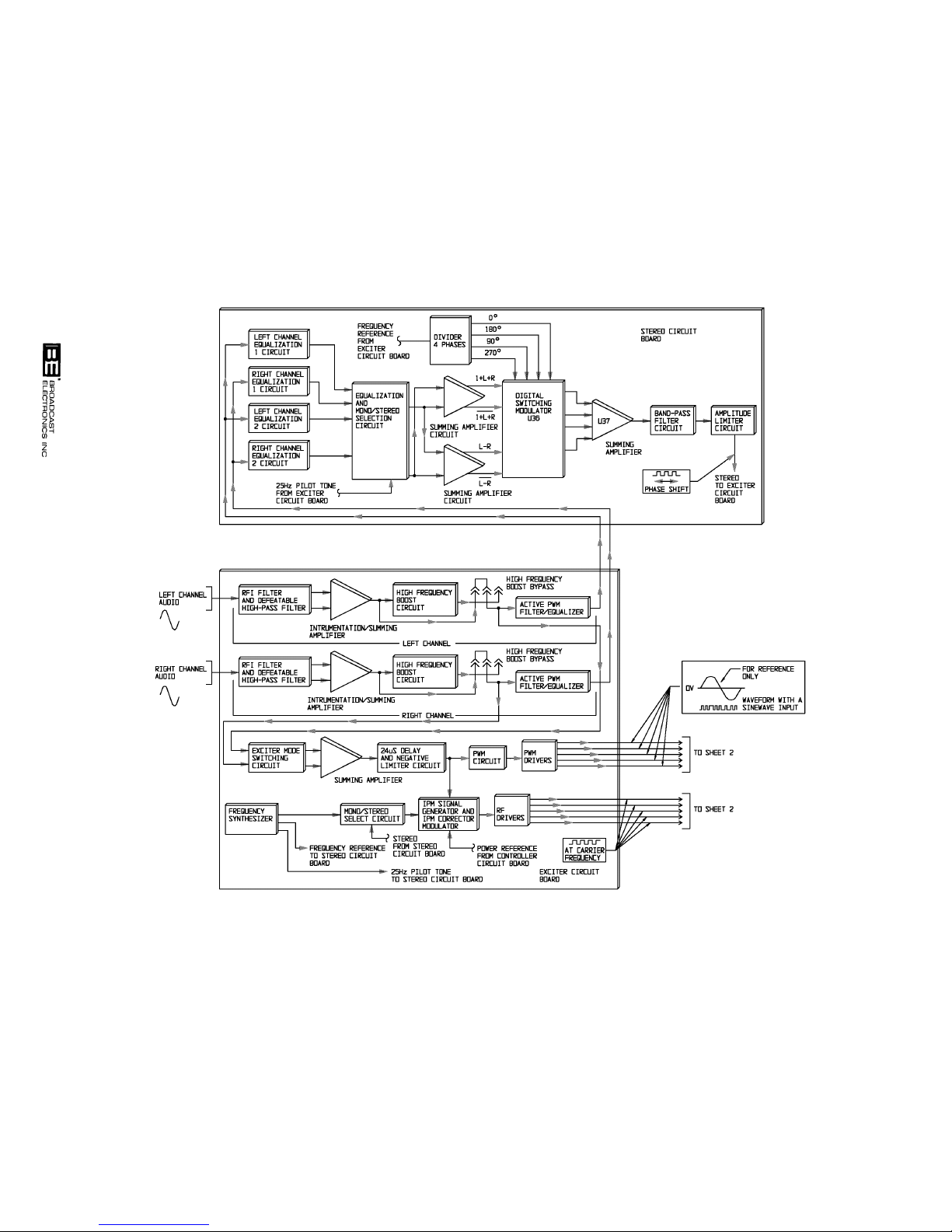
4-18
FIGURE 4-4. AM-2.5E/AM-5E RF CIRCUITRY SIMPLIFIED SCHEMATIC (SHEET 1 OF 2)
597-1113-18
COPYRIGHT 1999 BROADCAST ELECTRONICS, INC
Page 81
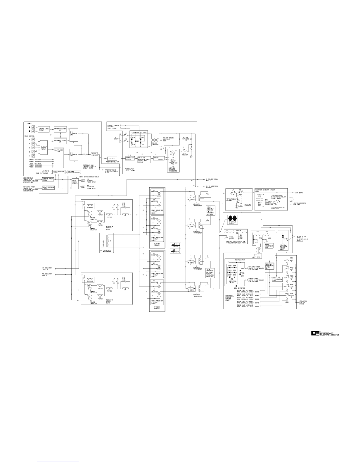
597-1113-18A
FIGURE 4-4. AM-2.5E/AM-5E RF CIRCUITRY
SIMPLIFIED SCHEMATIC (SHEET 2 OF 2)
(4-19/4-20)
COPYRIGHT 1999 BROADCAST ELECTRONICS, INC
Page 82

4-103. Modulator Circuit Board. The modulator circuit board consists of a MOSFET forward
converter circuit and a filter network. The forward converter circuit consists of MOSFET
transistors Q1 and Q2. The filter network consists of inductors L1 through L3 and
capacitors C13 through C16. A dc operating voltage for transistors Q1 and Q2 is provided
by the power supply circuit board. The B- leg of the supply is routed through relay K1 to
the transistors. K1 is provided to immediately terminate the supply during a modulator
fault condition.
4-104. The PWM signal at a 15 volt level from the exciter circuit board is applied to the gates of
MOSFET transistors Q1 and Q2. Q1/Q2 function to switch the B- leg at a 122 kHz to 135
kHz rate. The output from Q1/Q2 is applied to the LC low-pass filter network to convert
the square-wave PWM signal to a dc voltage. The output from the filter will produce a 50
volt dc signal with: 1) a nominal PWM duty cycle of 40% and 2) no audio modulation.
The dc voltage will vary from 0 to 125 volts with -100% to +150% modulation. The output
of the filter network is applied to the drains of MOSFET amplifier transistors on the
power amplifier circuit boards.
4-105. Power Amplifier Circuit Boards. The RF circuitry on the power amplifier circuit boards
consists of a Class E MOSFET power amplifier circuit. Each power amplifier circuit
board is designed to output approximately 350 watts. The power amplifier circuit boards
are identical. Therefore, only power amplifier 1 will be discussed.
4-106. The MOSFET amplifier circuit is designed in a push-pull design Class E configuration.
Class E power amplifier characteristics consist of: 1) the transistor drain-to-source
voltage must be nominally zero immediately prior to the turn-on of the transistor and
2) the time slope of the drain-to-source voltage waveform must be nominally zero prior to
the turn-on of the transistor. The Class E circuit results in: 1) lower device dissipation
resulting in reduced transistor operating temperature which greatly increases component
life, 2) an operating efficiency of 95% or greater, and 3) increased reliability when
operated into VSWR conditions.
4-107. Additional characteristics of a Class E amplifier design is the application of dc power to
the amplifier transistors. The B+ leg of the B supply is applied to RF choke L1. The
choke is connected to the primary center tap winding of combiner transformer T1. The
transistors are connected to the primary winding of the transformers.
4-108. Two signals are applied to the power amplifier 1 circuit board: 1) an RF square-wave
signal from the driver circuit board and 2) a dc voltage from the modulator circuit board
which varies at an audio rate. The RF square-wave signal at the carrier frequency is
applied to the gates of MOSFETs Q1 and Q2. The varying dc voltage from the modulator
circuit board is applied to the source of MOSFETs Q1 and Q2. Q1/Q2 operate in a
push-pull configuration to develop approximately 350 watts of RF power at combiner
transformer T1. The power at transformer T1 is combined with the 687.5 watts of RF
power from power amplifier circuit board 2 to generate 1375 watts of RF power from the
RF power module.
4-109.
RF COMBINER. The RF combiner components are located on the rear-panel of each
power block assembly. The combiner consists of a star combiner design. The star
combiner contains an individual transformer, an RF choke, and an impedance matching
circuit for each power amplifier circuit board. The impedance matching circuit consists of
star inductors. The circuit presents the correct impedance when a module is removed
from the chassis. This allows the transmitter to operate at an output power which is
proportional to the modules removed from the power block chassis.
4-21
Page 83

4-110. HARMONIC BAND-PASS FILTER. The output signal harmonic and spur frequencies are
reduced to FCC, DOC, and CCIR levels by a band-pass filter. The filter consists of a
fourth order LC network consisting of inductors L1 through L3 and capacitors C1 through
C4. The components are located in the output network assembly and are frequency
dependent. The output of the filter is routed to the directional coupler circuit board.
4-111.
4-112. Forward And Reflected Power Sample Circuit. A voltage sample from the RF output is
4-113. Modulation Monitor Calibration Circuit. A voltage sample for application to the
4-114. A voltage is applied to the modulation monitor receptacle when the power level 5
DIRECTIONAL COUPLER CIRCUIT BOARD. Transmitter forward and reflected power
are sampled by a directional coupler circuit board. The directional coupler circuit board is
designed to: 1) process the forward and reflected power samples for application to the
controller circuit board and 2) calibrate the RF modulation monitor sample.
obtained by transformer T203. A current sample of the RF output is obtained by
transformers T201 and T202. The current sample is converted to a voltage by a resistor
network and applied to transformer T203. A voltage proportional to the square root of the
forward power is obtained by summing the voltage from the secondary of T203 with the
voltage sample from T201. A voltage proportional to the square root of the reflected
power is obtained by summing the voltage from the secondary of T203 and with the
voltage sample from T202. The forward power sample voltage is half-wave rectified by
diode D202. The reflected power sample voltage is half-wave rectified by diode D201.
Diodes D205 through D208 and zener diodes D209 and D210 protect the rectifier diodes
from overvoltage conditions. The rectified forward and reflected power samples are
routed for application to the controller circuit board. Programmable header J206 is
provided to increase the adjustment range of the directional coupler circuitry. The header
is programmed at the factory for the adjustment range required by the transmitter.
modulation monitor calibration circuit is provided by the lightning detection circuit board.
A sample from the RF output is obtained by a capacitor circuit and applied to a relay
circuit on the directional coupler circuit board. The relay circuit is designed to select a
voltage sample from a calibration potentiometer for application to the modulation monitor
receptacle. The relays are controlled by power level 1 through 5 commands from the
controller circuit board. Each relay circuit operates in an identical manner, therefore only
the circuit for power level 5 will be explained.
command energizes relay K201. K201 applies a sample voltage to power level 5
modulation monitor calibration control R201. R201 is provided to obtain a 2 volt RMS
sample to the modulation monitor receptacle. Frequency programming switch S201 is
provided to compensate the RF sample for frequencies within the AM band for power
levels 1 through 3. Power level programming switch P203 is provided to program the
power level 3 circuit for low power range or high power range operation. The calibrated
sample from potentiometer R201 is applied to the modulation monitor receptacle.
4-115.
4-116. LIGHTNING PROTECTION CIRCUIT BOARD. The transmitter is protected from
T-MATCHING NETWORK. Output matching to antenna loads for up to a VSWR
condition of 1.4:1 at any phase angle relative to the 50 Ohm load is provided by a
T-matching network. The T-matching network consists of tune control L4, load control
L6, inductor L5 and capacitor C5/C5A. Inductor L5 and capacitor C5/C5A are frequency
dependent components. The tune and load controls are designed to be adjusted to present
the optimum impedance for the power amplifier modules.
lightning potentials present at the output network by the lightning protection circuit
board. The circuit board consists of series connected transzorbs. The AM-2.5E
transmitter is equipped with transzorbs D1 through D6. The AM-5E transmitter is
equipped with transzorbs D1 through D7. The transzorbs are designed to conduct the
lightning potentials to ground prior to the operation of the lightning detection circuit
spark-gap.
4-22
Page 84

4-117. LIGHTNING DETECTION CIRCUIT BOARD. Lightning potentials present at the
transmitter output are detected by the lightning detection circuit board. The circuit
board is equipped with an RF sampling circuit and an optically operated transistor
circuit.
4-118. The RF sampling circuit consists of a parallel capacitor circuit. The circuit is designed to
provide a constant RF voltage sample for application to the directional coupler circuit
board. The optically operated transistor circuit is designed to detect lightning potentials
present at the transmitter output. The circuit operates in association with the lightning
detector spark-gap. When lightning is present at the transmitter RF output, the
spark-gap will: 1) be biased on to conduct the potential to ground and 2) emit a light
pulse to optically operated transistor Q401. Q401 will be biased on to output a lightning
detect signal to the controller circuit board.
4-119.
RF OUTPUT POWER CONTROL CIRCUITRY. The transmitter output power is controlled
by circuitry on the controller and power supply circuit boards. The transmitter power
level is controlled by a Pulse-Width-Modulated (PWM) signal generated by the controller
circuit board. The power control PWM signal is routed for application to the power
supply circuit board(s). The power supply circuit board(s) respond by routing the
required dc voltage to the modulator circuit boards and the RF amplifier circuit boards.
The following text presents a description of the RF power control circuitry.
4-120. RF Output Power Control - Controller Circuit Board. A transmitter RF output power level
is selected by the power control 1 through power control 5 switch/indicators. The power
control switch/indicators route a LOW control signal to a priority encoder circuit. The
priority encoder circuit determines which control pulse is routed to the power control
circuitry. The circuit allows transmitter off commands to be assigned a high priority.
With no transmitter off commands present, the power control signal is applied to
multiplexer U39. U39 selects a reference voltage from the power control potentiometers
on the controller circuit board. The potentiometers are designed to establish a preset
transmitter power level such as 1 kW. The voltage is used as the reference for
digital-to-analog converter U42. With no fault conditions present, the voltage is applied
without change to power trim digital-to-analog converter U43. With no power trim
commands present, the reference voltage is applied to a driver circuit which converts the
dc control voltage to a power control PWM signal. The power control PWM duty cycle
responds to the changes in the voltage reference level. When the voltage reference
increases, the power control PWM signal duty-cycle increases. When the voltage
reference decreases, the power control PWM signal duty-cycle decreases. The power
control PWM signal is routed for application to the power supply circuit board(s).
4-121. The transmitter output power level is trimmed to a precise level by the power up and
down switches. The switches output a LOW control signal to a control logic circuit. The
control logic circuit generates the required control signals to drive an up/down counter
circuit. The circuit is designed to: 1) count up if power is required to be increased or
2) count down if power is required to be decreased. The up/down counter circuit output is
converted to a dc potential by digital-to-analog converter U43. The output of U43 is
summed with the dc potential from power control switch digital-to-analog converter U42
to generate a dc power control signal. The power control signal is applied to the driver
circuit which converts the signal to a power control PWM signal.
4-122. Automatic Power Control Circuitry. The transmitter power control circuitry is equipped
with several monitor circuits designed to determine if power control correction is required
during adverse operating conditions. Circuitry on the controller circuit board monitors
the transmitter components and the RF output for: 1) lightning, 2) high forward power,
3) high reflected power, and 4) over-temperature. If a lightning, high forward power,
high reflected power, or over-temperature, condition occurs, a signal is routed to the
fault detection circuit.
4-23
Page 85

4-123. The fault detection circuit: 1) processes lightning and over-temperature signals and
2) analyzes forward and reflected power signals. As determined by the the fault
condition, the fault detection circuit will generate a fast or slow control signal to the
up/down counter circuit. The counter circuit will respond by decreasing the power control
voltage at digital-to-analog converter U42. U42 will respond by decreasing the output
power to an acceptable level. Once the condition which caused the fault to occur is
removed, the fault detection circuitry will automatically output a control signal to
increase power to a normal level.
4-124. Forward/Reflected Power Circuitry. Samples of the transmitter forward and reflected
power are processed by forward and reflected power circuits on the controller circuit
board. Forward power samples from the directional coupler circuit board are applied to
the forward power circuit. The forward power circuit converts the sample into a dc signal
for application to the fault detection circuitry and to the meter switch circuit board.
Reflected power samples from the directional coupler circuit board are applied to the
reflected power circuit. The reflected power circuit converts the sample into a dc signal
for application to the fault detection circuit and the meter switch circuit board.
4-125. Meter Switch Circuit Board. Forward and Reflected power samples from the controller
circuit board are applied to the meter switch circuit board. The circuit board allows the
selection of forward power, reflected power, and ac input samples for display on forward
power meter M1 and reflected power meter M2.
4-126. RF Output Power Control - Power Supply Circuit Board/RF Power Modules. The power
control PWM signal from the controller circuit board is applied to a correction circuit on
the power supply circuit board. The PWM signal is converted to a dc signal and combined
with a dc feedback signal to generate a power control signal for application to the switch
regulator power control PWM circuit. The circuit converts the dc signal into two PWM
180 degree out-of-phase square-wave drive signals. The square-wave drive signals are
applied to a driver circuit. The driver circuit outputs the out-of-phase square-wave
signals to an IGBT transistor regulator circuit. The regulator circuit transistors are
operated to on for a specific time duration to generate a specific B- supply voltage. The
B- supply voltage is filtered by capacitor C55 and applied to the forward power converter
on the modulator circuit boards.
4-127. The main operating supply B+ leg is created by a SCR controlled bridge rectifier circuit.
AC power from an ac input filter is applied to the SCR controlled bridge rectifier. The
rectifier is controlled by a soft-start circuit. The full-wave rectified dc potential is filtered
by capacitors C24 through C27. The output of the filter generates the positive leg of a B
supply. The B+ line of the power supply is applied to the forward power converter circuit
on modulator circuit boards and the RF amplifier transistors on RF amplifier circuit
boards.
4-128. To provide an example of output power control operation, a 10 kW output level is required
from the transmitter. The controller power control PWM duty-cycle will be
approximately 85%. The power supply will respond by generating a 120 volt B- supply
for application to the forward power converter on the modulator circuit boards. The
modulator circuit boards will output a dc voltage which varies at an audio rate to the
amplifier circuit boards. The amplifier circuit boards will respond by using the modulator
circuit board dc voltage and the B+ leg of the main supply to amplify the RF drive signal
from the exciter circuit board.
4-24
Page 86

SECTION V
MAINTENANCE
5-1. INTRODUCTION.
5-2. This section provides maintenance information, electrical adjustment procedures, and
troubleshooting information for the Broadcast Electronics AM-2.5E and AM-5E
transmitters.
5-3.
SAFETY CONSIDERATIONS.
WARNING
THE TRANSMITTER CONTAINS MULTIPLE CIRCUIT
GROUNDS WITH HIGH AC AND DC POTENTIALS
WARNING
WARNING
WARNING
WITH RESPECT TO THE CABINET WHICH IS AT
EARTH POTENTIAL. DO NOT ENERGIZE THE
TRANSMITTER WITH TEST EQUIPMENT CON
NECTED TO THE TRANSMITTER OUTPUT
NETWORK, RF POWER MODULE, RF COMBINER, OR
POWER SUPPLY COMPONENTS.
5-4. The AM-2.5E/AM-5E transmitters contain high voltages and currents. If safety
precautions are not practiced, contact with the high voltages and currents could cause
serious injury or death. The transmitter is equipped with many built-in safety features,
however good judgement, care, and common sense must be practiced to prevent accidents.
5-5. In addition to high voltages and currents, the transmitter contains multiple circuit
grounds with high ac and dc potentials with respect to the cabinet which is at earth
potential. The potentials could cause serious injury or death if maintenance personnel
simultaneously touch a circuit ground and the cabinet. As a result, operation of the
transmitter with test equipment connected to transmitter output network, RF power
module, RF combiner, or power supply components is extremely dangerous and must not
be attempted. Therefore, never energize the transmitter with test equipment connected
to the transmitter output network, RF power module, RF combiner, or power supply
components. Test equipment may be connected to the ECU circuit boards from the front
of the transmitter using the supplied extender circuit board with power energized. The
maintenance procedures presented in this section should be performed only by trained
and experienced maintenance personnel.
5-6.
5-7. First level maintenance consists of procedures applied to the equipment to prevent future
5-8.
FIRST LEVEL MAINTENANCE.
failures. The procedures are performed on a regular basis and the results recorded in a
maintenance log. Preventive maintenance of the transmitter consists of good
housekeeping and checking performance levels using the meters and various indicators
built into the equipment.
ROUTINE MAINTENANCE.
WARNING: DISCONNECT POWER PRIOR TO SERVICING
5-1
Page 87

WARNING
NEVER OPEN THE EQUIPMENT UNLESS ALL TRANS
MITTER PRIMARY POWER IS DISCONNECTED. EN
WARNING
SURE ALL TRANSMITTER PRIMARY POWER IS DIS
CONNECTED BEFORE ATTEMPTING MAINTENANCE
ON ANY AREA WITHIN THE TRANSMITTER.
5-9. INSPECTION AND CLEANING. On a regular basis, clean the equipment of accumulated
dust using a brush and vacuum cleaner. Inspect the modulator circuit boards, RF
amplifier circuit boards, and the power supply circuit boards for damage caused by
components overheating. Overheated components are identified by circuit board
discoloration near the component leads. Inspect the circuit boards for loose hardware as
required.
5-10.
5-11.
5-12.
CONTROLLER BATTERY. Periodically, the controller battery in the ECU assembly should
be checked by depressing the battery test switch on the controller circuit board. The
battery test indicator will illuminate to indicate the battery is operational. If the battery
test indicator fails to illuminate, the battery must be replaced. A good-quality Alkaline
battery is recommended for replacement. Typically, it is recommended the controller
battery be replaced annually.
AIR FILTERS. The AM-2.5E/AM-5E transmitters are equipped with a single screen-type
air filter. The screen filter is designed to be removed and cleaned using a brush and
vacuum. A dirty filter results in restricted air flow and increased operating temperatures
for the transmitter solid-state components. Check the filter approximately once a week.
The filter is designed to be removed during transmitter operation. To remove the filter,
proceed as follows:
1. Refer to Figure 5-1 and remove the six filter housing screws.
2. Using the handles, lift the filter housing off of the rear door.
3. Remove the filter.
FLUSHING FANS. Inspect the transmitter flushing fans for dust accumulation and
periodically clean the fans using a brush and vacuum cleaner. Do not use compressed air
and an air gun. The fans are cooled by air passing around each motor. If dust is allowed
to accumulate on the motors, the ambient air temperature will increase due to restricted
air flow. When the ambient air temperature increases, the fan motor bearing lubricant
will gradually vaporize and bearing failure will occur.
5-13. It is recommended the flushing fan mounting hardware be periodically checked. The
flushing fans are equipped with sealed bearings which do not permit lubrication. If a
bearing fails, the motor must be replaced.
5-14.
5-15. SECOND LEVEL MAINTENANCE.
5-16. Second level maintenance consists of procedures required to adjust the transmitter
SPARK GAP. The output network is equipped with a spark gap. The spark gap is
provided to safely conduct lightning potentials appearing at the transmitter output to
ground. Inspect the spark gap annually to ensure the gap is operational.
circuitry or restore the transmitter to operation after a fault has occurred. The
procedures consist of electrical adjustments, troubleshooting, and component replacement
procedures.
WARNING: DISCONNECT POWER PRIOR TO SERVICING
5-2
Page 88
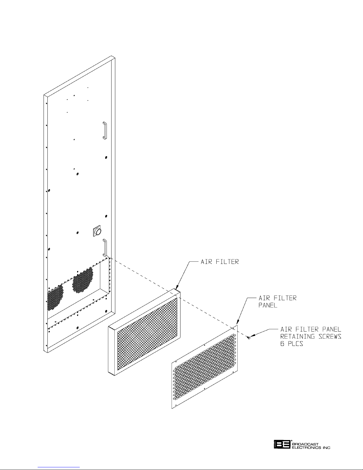
FIGURE 5-1. REMOVING THE AIR FILTER
WARNING: DISCONNECT POWER PRIOR TO SERVICING
COPYRIGHT 1999 BROADCAST ELECTRONICS, INC
597-1114-15
5-3
Page 89

WARNING
NEVER OPEN THE EQUIPMENT UNLESS ALL TRANS
MITTER PRIMARY POWER IS DISCONNECTED. EN
WARNING
SURE ALL TRANSMITTER PRIMARY POWER IS DIS
CONNECTED BEFORE ATTEMPTING MAINTENANCE
ON ANY AREA WITHIN THE TRANSMITTER.
5-17. The maintenance philosophy for the AM-2.5E/AM-5E transmitters consists of isolating a
problem to a specific area. Once the specific area is located, subsequent troubleshooting
using the information in the following text and the modular sections in PART II of this
manual will assist in problem isolation to a replaceable assembly or component. If
required, the assembly may be: 1) returned to the factory for repair or exchange or
2) repaired locally.
5-18.
ELECTRICAL ADJUSTMENTS.
WARNING
NEVER OPEN THE EQUIPMENT UNLESS ALL TRANS
MITTER PRIMARY POWER IS DISCONNECTED. EN
WARNING
SURE ALL TRANSMITTER PRIMARY POWER IS DIS
CONNECTED BEFORE ATTEMPTING MAINTENANCE
ON ANY AREA WITHIN THE TRANSMITTER.
5-19. Adjustment procedures for controls associated with the transmitter circuitry is presented
in the ECU, output network, RF power module, and power supply module sections of this
manual. Determine the transmitter modular component requiring adjustment and refer
to the appropriate section of this manual for the adjustment procedures.
5-20.
5-21. The AM-2.5E/AM-5E transmitters are configured for a specific frequency when shipped
5-22.
TRANSMITTER FREQUENCY RE-PROGRAMMING.
from the factory. The transmitters are equipped with several frequency dependent parts
and circuits. Due to the frequency dependent parts, frequency dependent circuits, and
specialized procedures, the transmitters can not be reprogrammed for a different
frequency in the field. If a transmitter is required to be programmed for a different
frequency, contact the Broadcast Electronics Customer Service department.
TROUBLESHOOTING.
WARNING: DISCONNECT POWER PRIOR TO SERVICING
5-4
Page 90
WARNING
THE TRANSMITTER CONTAINS MULTIPLE CIRCUIT
GROUNDS WITH HIGH AC AND DC POTENTIALS
WARNING
WARNING
WARNING
WITH RESPECT TO THE CABINET WHICH IS AT
EARTH POTENTIAL. DO NOT ENERGIZE THE
TRANSMITTER WITH TEST EQUIPMENT CON
NECTED TO THE TRANSMITTER OUTPUT
NETWORK, RF POWER MODULE, RF COMBINER, OR
POWER SUPPLY COMPONENTS.
5-23. The AM-2.5E/AM-5E transmitters are equipped with extensive indicator and meter
circuitry to allow the operator to isolate problems to a specific area within the transmitter.
Due to the hazardous voltages and currents contained in the equipment, operation of the
transmitter with test equipment connected to transmitter output network, RF power
module, RF combiner, or power supply components is extremely dangerous and must not
be attempted. Test equipment may be connected to the ECU circuit boards from the front
of the transmitter using the supplied extender circuit board with power energized.
Therefore, the transmitter indicators and meters must be used to isolate a problem to a
specific area.
5-24.
TRANSMITTER INDICATORS. The following text presents a description of the transmitter
indicators and typical meter indications. Refer to the following text as required to
determine the function of a specific indicator.
ASSEMBLY INDICATOR FUNCTION
ECU ASSEMBLY
TRANSMITTER MONITOR
EXCITER GREEN DISPLAY - Indicates normal exciter
POWER MODULES GREEN DISPLAY - Indicates all RF power modules
POWER SUPPLY GREEN DISPLAY - Indicates normal power supply
TABLE 5-1. AM-2.5E/AM-5E INDICATORS
(Sheet 1 of 4)
operation.
RED DISPLAY - Indicates no exciter RF drive or
PWM output.
are operating normally.
YELLOW DISPLAY - Indicates one or more RF power
modules are removed from the transmitter for
maintenance.
RED DISPLAY - Indicates a modulator or power
amplifier circuit board fault in one or more RF power
modules.
operation.
RED DISPLAY - Indicates an open loop or overvoltage fault in one or more power supply modules.
YELLOW Display - Indicates one or more power
supplies are removed from the transmitter.
WARNING: DISCONNECT POWER PRIOR TO SERVICING
5-5
Page 91

TABLE 5-1. AM-2.5E/AM-5E INDICATORS
(Sheet 2 of 4)
ASSEMBLY INDICATOR FUNCTION
ANTENNA VSWR GREEN DISPLAY - Indicates a normal antenna load.
YELLOW DISPLAY - Indicates a VSWR condition of
1.2:1.
RED Display - Indicates a high reflected/forward
power condition. In the AM-2.5E, indicates a 100 watt
reflected power condition or a condition which results
in a high forward power indication of greater than 20%.
In the AM-5E, indicates a 200 watt reflected power
condition or a condition which results in a high forward
power indication of greater than 20%.
FLASHING RED Display - Indicates a reflected power
emergency condition. In the AM-2.5E, indicates a 500
watt reflected power condition. In the AM-5E,
indicates a 1000 watt reflected power condition.
REMOTE Illuminates to indicate transmitter remote control
operations are enabled. Extinguishes to indicate
transmitter remote control operations are disabled:
1) using the remote/local switch on the controller
circuit board or 2) due to a fault in the remote control
unit.
CONFLICT Illuminates to indicate an incorrect power level is
selected for operation into the antenna connected to the
transmitter.
LIGHTNING In the AM-2.5E, Illuminates to indicate a 1500 volt
or greater potential is present at the transmitter
output. In the AM-5E, illuminates to indicate a 2100
volt or greater potential is present at the transmitter
output.
INTERLOCK Illuminates to indicate all internal and external
interlocks are closed.
FOLDBACK Illuminates to indicate when the transmitter is in a
foldback condition. Foldback is when the transmitter
output power is automatically reduced in response to
one of the following fault conditions: 1) high reflected
power, 2) high forward power, 3) high temperature, or
4) detection of a lightning potential.
OVERTEMP Illuminates to indicate when the transmitter operating
temperature exceeds 70 °C (158 °F).
RESET Illuminates to indicate one or more of the following
transmitter faults have occurred: 1) over-temperature,
2) exciter fault, 3) power supply fault, 4) RF power
module fault, 5) high reflected power, 6) reflected power
emergency, or 7) lightning. Once the fault condition is
removed, the fault circuitry must be reset.
WARNING: DISCONNECT POWER PRIOR TO SERVICING
5-6
Page 92

TABLE 5-1. AM2.5E/AM-5E INDICATORS
(Sheet 3 of 4)
ASSEMBLY INDICATOR FUNCTION
CONTROLLER CIRCUIT BOARD
PWM Mute Illuminates to indicate the power control PWM signal is
muted in response to a fault such as lightning, an exciter
fault, a reflected power emergency, an open remote
control failsafe, an external transmitter mute, lightning,
or high reflected or forward power.
Remote Failsafe Illuminates to indicate the remote control unit is
enabled.
Battery OK When the battery test switch is depressed, the indicator
will: 1) illuminate to indicate the battery is operational
or 2) not illuminate to indicate the battery is to be
replaced.
STEREO CIRCUIT BOARD
Stereo Equalization 1 Illuminates to indicate stereo equalization circuit 1 is
active.
Stereo Equalization 2 Illuminates to indicate stereo equalization circuit 2 is
active.
EXCITER CIRCUIT BOARD
Exciter Lock Illuminates to indicate the exciter is locked to the
programmed carrier frequency.
Exciter +5V Illuminates to indicate the ECU +5V supply is
operational.
Exciter +15V Illuminates to indicate the ECU +15V supply is
operational.
Exciter -15V Illuminates to indicate the ECU -15V supply is
operational.
RF POWER MODULE
PA 1 RF DRIVE Illuminates to indicate RF drive from the exciter circuit
board is present at power amplifier 1.
PA 1 FAULT Illuminates to indicate a fault has occurred in power
amplifier 1.
PA 2 RF DRIVE Illuminates to indicate RF drive from the exciter circuit
board is present at power amplifier 2.
PA 2 FAULT Illuminates to indicate a fault has occurred in power
amplifier 2.
WARNING: DISCONNECT POWER PRIOR TO SERVICING
5-7
Page 93

TABLE 5-1. AM-2.5E/AM-5E INDICATORS
(Sheet 4 of 4)
ASSEMBLY INDICATOR FUNCTION
MOD PWM DRIVE Illuminates to indicate the PWM drive signal from the
exciter is present at the modulator circuit board.
MOD POWER Illuminates to indicate dc power from the power supply
circuit board is present at the modulator circuit board.
MOD FAULT Illuminates to indicate a modulator, fuse, or power
supply fault has occurred in the modulator circuit board.
MOD FUSE Illuminates to indicate the modulator circuit board fuse
has blown.
POWER SUPPLY 1-2 Illuminates to indicate an open loop, over-current,
or over-voltage fault in the 1-2 power supply. The
supply provides power for modules 1-2.
POWER SUPPLY 3-4 Illuminates to indicate an open loop, over-current,
(AM-5E Only) or over-voltage fault in the 3-4 power supply. The
supply provides power for modules 3-4.
Exciter -15V Illuminates to indicate the ECU -15V supply is
operational.
CAUTION
WHEN AC POWER IS APPLIED TO THE TRANSMIT
TER AND THE RF DRIVE AND PWM DRIVE INDICA
CAUTION
TORS ON RF POWER MODULES IN A POWER BLOCK
ARE EXTINGUISHED, THE RF POWER MODULES
MUST BE REMOVED FROM THE TRANSMITTER
CHASSIS TO PREVENT DAMAGE TO THE MODULES.
5-25. RF POWER MODULE REMOVAL. When ac power is applied to the transmitter, check the
RF DRIVE and PWM DRIVE indicators on the RF power modules. If the RF DRIVE
and PWM DRIVE indicators on RF power modules in a power block are extinguished, the
RF power modules must be removed from the transmitter to prevent damage to the
modules.
5-26.
5-27.
TRANSMITTER TROUBLESHOOTING PROCEDURES. Table 5-2 presents troubleshooting
information for the AM-2.5E/AM-5E transmitters. Refer to Table 5-2 to isolate the
problem to a specific assembly. Once the trouble is isolated, refer to the applicable
modular section of this manual for the theory of operation and schematic diagrams to
assist in problem resolution.
TRANSMITTER COMPONENT LOCATIONS. Figures 5-2 through 5-4 present
transmitter component locations. Refer to Figures 5-2 to 5-4 as required during the
troubleshooting procedures to locate components within the transmitter.
WARNING: DISCONNECT POWER PRIOR TO SERVICING
5-8
Page 94

TABLE 5-2. AM-2.5E/AM-5E TROUBLESHOOTING
(Sheet 1 of 5)
SYMPTOM CIRCUITRY TO CHECK
NO OUTPUT POWER 1. Check the ac line voltage using the reflected power/
NO NORMAL/FAULT ac voltage meter. If no line voltage is present, check
INDICATIONS fuses F1 and F2.
2. Check the ±15 volt and +5 volt indicators on the
exciter circuit board. If no indicators are
illuminated, check the ECU power supply.
NO OUTPUT POWER 1. Transmitter operated to off due to 7 on/off cycles
NORMAL INDICATIONS within 15 seconds. Operate the transmitter to on
NO CONTROL OPERATIONS as follows: 1) do not depress any controller
switch/indicators for approximately 30 seconds and
2) depress the desired power level switch/indicator.
2. Refer to the POWER SUPPLY section and
troubleshoot the power supply circuit board for no
120 Hz signal output.
RED EXCITER INDICATION 1. Check the lock indicator on the exciter circuit
board. If the lock indicator is not illuminated, refer
to the ECU section and troubleshoot the exciter
circuit board for lock indicator extinguished.
2. Remove the stereo circuit board and perform the
following: 1) depress the RESET switch and
2) initiate transmitter operation. If the transmitter
will not operate, refer to the ECU section and
troubleshoot the exciter circuit board. If the
transmitter operates, refer to the ECU section and
troubleshoot the stereo circuit board.
YELLOW POWER MODULE 1. Indicates one or more RF power modules are
INDICATION removed from the transmitter.
RED POWER MODULE 1. Refer to the RF POWER MODULE section and
INDICATION RED FAULT troubleshoot the RF power module.
INDICATION ON A MODULE 2. Visually inspect the RF power module combiner
panel for discolored components.
YELLOW POWER SUPPLY 1. Indicates one or more power supply modules are
INDICATION removed from the transmitter.
RED POWER SUPPLY 1. Check for an over-temperature condition by
INDICATION inspecting the fans and filter.
2. If the fans and filter are normal, use the power supply
fault display circuit boards in each cabinet to
determine the defective power supply module. When
the defective power supply is located, refer to the
POWER SUPPLY MODULE section and troubleshoot
the power supply module.
5-9
WARNING: DISCONNECT POWER PRIOR TO SERVICING
Page 95

TABLE 5-2. AM-2.5E/AM-5E TROUBLESHOOTING
(Sheet 2 of 5)
SYMPTOM CIRCUITRY TO CHECK
YELLOW ANTENNA INDICATION 1. Check the antenna and phasor equipment.
2. Visually inspect the T-matching network for
discolored components.
3. Refer to the OUTPUT NETWORK section and
troubleshoot the directional coupler circuit board.
RED ANTENNA INDICATION 1. Check the antenna and phasor equipment.
2. Visually inspect the T-matching network for
discolored components.
3. Refer to the OUTPUT NETWORK section of this
manual and troubleshoot the directional coupler
circuit board.
FLASHING RED ANTENNA 1. Check the antenna and phasor equipment.
INDICATION 2. Visually inspect the spark gap in the output network
assembly for a short circuit condition.
3. Check the antenna shorting switch on the output
network assembly.
4. Visually inspect the T-matching network capacitors
in the output network assembly for a short circuit
condition.
5. Check the lightning protection circuit board in the
output network assembly for a short circuit
condition.
INTERLOCK INDICATOR 1. Operate remote/local switch to local.
EXTINGUISHED WHEN IN THE A. If the interlock indicator illuminates, ensure
REMOTE CONTROL MODE a +5 volt signal is applied to remote failsafe
input J1-23 on the ECU rear-panel when the
remote control unit is enabled.
1. If the +5 volt signal is not present, troubleshoot
the remote control unit.
2. If the +5 volt signal is present, check Q48 and
U56 on the controller circuit board.
B. If the interlock indicator is extinguished,
check the cabinet and the external interlocks.
CONFLICT INDICATION 1. Ensure a +5 volt status signal from the selected
antenna is applied to the antenna A, B, or C input
on the ECU rear-panel.
2. Ensure the correct transmitter power level is
selected for operation into the antenna.
3. Check the antenna interlock circuit programming on
the controller circuit board.
4. Refer to the ECU section and troubleshoot the
controller circuit board for a conflict indication.
WARNING: DISCONNECT POWER PRIOR TO SERVICING
5-10
Page 96

TABLE 5-2. AM-2.5E/AM-5E TROUBLESHOOTING
(Sheet 3 of 5)
SYMPTOM CIRCUITRY TO CHECK
NO OUTPUT POWER 1. Transmitter operated to off due to 7 on/off cycles
LIGHTNING INDICATOR within 15 seconds. Operate the transmitter to
ILLUMINATED on as follows: 1) do not depress any controller
switch/indicators for approximately 30 seconds
and 2) depress the desired power level
switch/indicator.
2. Ensure J1 on output network is connected.
3. Check Q401 on the lightning detection circuit board.
NORMAL OUTPUT POWER 1. Indicates the presence of lightning at the output of
LIGHTNING INDICATOR transmitter. Depress the RESET switch to reset the
ILLUMINATED indicator.
INTERLOCK INDICATOR 1. Ensure a +5 volt signal is applied to external
EXTINGUISHED interlock input J1-23 on the ECU rear panel.
OVERTEMP INDICATOR 1. Ensure the transmitter air filter is clean.
ILLUMINATED 2. Check the transmitter fans in each cabinet. If the
fans are not operating, check optical-coupled-relay
(OCR) K1.
3. Ensure the transmitter exhaust area is clear of
obstructions.
MISSING NORMAL/FAULT 1. Check the fuses for the power supply: 1) power
INDICATIONS FOR A POWER supply 1-2 = F6 and F7, 2) power supply 3-4 =
BLOCK F8 and F9 (AM-5E only).
2. Check power transformer T1 on the power supply
panel.
NO L+R MODULATION ACTIVITY 1. Ensure audio is present at J3-1/J3-2/J3-4/J3-5
DURING MONO OPERATION on the ECU rear panel.
2. Check for audio at J101-29 through J101-31 and
J101-36/J101-37 on the ECU motherboard. If no
audio is present, check the filter components on the
ECU motherboard.
3. Refer to the ECU section and troubleshoot the
exciter circuit board.
NO L+R MODULATION ACTIVITY 1. Ensure audio is present at J3-1/J3-2/J3-4/J3-5 on
DURING STEREO OPERATION the ECU rear panel.
2. Check for audio at J101-29 through J101-31 and
J101-36/J101-37 on the ECU motherboard. If no
audio is present, check the filter components on the
ECU motherboard.
3. Refer to the ECU section and troubleshoot the
exciter circuit board.
WARNING: DISCONNECT POWER PRIOR TO SERVICING
5-11
Page 97

TABLE 5-2. AM-2.5E/AM-5E TROUBLESHOOTING
(Sheet 4 of 5)
SYMPTOM CIRCUITRY TO CHECK
RF DRIVE INDICATORS 1. Check the RF drive output on the ECU motherboard
EXTINGUISHED FOR A as follows: 1) output 1 -P101-7 and 2) output 2 POWER BLOCK P101-47 (AM-5E only).
1. If no RF drive is present, refer to the ECU
section and troubleshoot the exciter circuit board.
2. If RF drive is present at the exciter circuit board,
check bridge rectifiers D10 and D11 on the power
supply module for the power block.
2. Refer to the RF POWER MODULE section and
troubleshoot each RF power module.
LOW DEMODULATOR LEFT 1. Refer to the ECU section and troubleshoot the
CHANNEL MODULATION LEVEL exciter circuit board.
WITH LOW EXCITER
MONITOR LEFT CHANNEL
MODULATION LEVEL
LOW DEMODULATOR RIGHT 1. Refer to the ECU section and troubleshoot the
CHANNEL MODULATION LEVEL exciter circuit board.
WITH LOW EXCITER
MONITOR RIGHT CHANNEL
MODULATION LEVEL
LOW DEMODULATOR LEFT 1. Refer to the ECU section and troubleshoot the
CHANNEL MODULATION LEVEL stereo circuit board.
WITH NORMAL EXCITER
MONITOR LEFT CHANNEL
MODULATION LEVEL
LOW DEMODULATOR RIGHT 1. Refer to the ECU section and troubleshoot the
CHANNEL MODULATION LEVEL stereo circuit board.
WITH NORMAL EXCITER
MONITOR RIGHT CHANNEL
MODULATION LEVEL
PWM DRIVE INDICATOR 1. Refer to the ECU section and troubleshoot the
EXTINGUISHED ON A POWER exciter circuit board.
BLOCK
PWM DRIVE AND RF DRIVE 1. Refer to the ECU section and troubleshoot the exciter
INDICATORS EXTINGUISHED circuit board.
ON ALL POWER BLOCKS
WARNING: DISCONNECT POWER PRIOR TO SERVICING
5-12
Page 98

TABLE 5-2. AM-2.5E/AM-5E TROUBLESHOOTING
(Sheet 5 of 5)
SYMPTOM CIRCUITRY TO CHECK
MOD PWR INDICATORS 1. Check for a power control PWM signal at the
EXTINGUISHED ON A POWER drain of Q22 on the controller circuit board.
BLOCK A. If the PWM signal is not present, refer to the
ECU section and troubleshoot the controller
circuit board for no power control PWM signal.
B. If the PWM output is present, check for a LOW at
Q13 on the controller circuit board.
1. If the LOW at Q13 is not present, refer to the
ECU section and troubleshoot the controller
circuit board for no transmitter on signal.
2. If the LOW at Q13 is present, refer to the
POWER SUPPLY section and troubleshoot the
power supply for no MOD POWER indicator on
a power block.
REFLECTED POWER METER 1. Narrow-band antenna. Contact the Broadcast
FLUCTUATES WITH MODULATION Electronics Customer Service Department.
FORWARD POWER METER 1. Enable the high-pass filter on the exciter circuit
FLUCTUATES WITH MODULATION board.
5-28. COMPONENT REPLACEMENT PROCEDURE. Component replacement on printed
circuit boards requires extreme care to avoid damage to the circuit board traces. The
following text describes the procedure to replace components on the circuit boards.
5-29. On all circuit boards, the adhesive securing the copper trace to the board melts at almost
the same temperature at which solder melts. A circuit board trace can be destroyed by
excessive heat or lateral movement during soldering. Use of a small iron with steady
pressure is required for circuit board repairs.
5-30. To remove a component from a circuit board, cut the leads from the body of the defective
component while the device is still soldered to the board.
5-31. Grip each component lead, one at a time, with long-nose pliers. Rotate the circuit board
and touch a soldering iron to the lead at the solder connection. When the solder begins to
melt, push the lead through the back side of the board. Each lead may now be heated
independently and pulled out of each hole. The holes may be cleared of solder by carefully
re-heating each hole with a low wattage iron and removing the residual solder with a
soldering vacuum tool.
WARNING: DISCONNECT POWER PRIOR TO SERVICING
5-13
Page 99

WARNING
MOST SOLVENTS WHICH WILL REMOVE ROSIN FLUX
ARE VOLATILE AND TOXIC BY THEIR NATURE AND
WARNING
WARNING
WARNING
5-32. Install the new component and apply solder from the bottom side of the circuit board.
After soldering, remove flux with a cotton swab moistened with a suitable solvent.
Rubbing alcohol is highly diluted and is not effective.
5-33. The board should be checked to ensure the flux has been removed and not just smeared.
Rosin flux is not normally corrosive, but rosin will absorb enough moisture in time to
become conductive and cause problems.
SHOULD BE USED ONLY IN SMALL AMOUNTS IN A
WELL VENTILATED AREA, AWAY FROM FLAME SUCH
AS FROM A SOLDERING IRON OR SMOKING MATERI
ALS. OBSERVE THE MANUFACTURER'S CAU
TIONARY INSTRUCTIONS.
5-34.
INTEGRATED CIRCUITS. Special care should be exercised with integrated circuits. Each
integrated circuit must be installed by matching the integrated circuit notch with the
notch on the socket. Do not attempt to remove an integrated circuit from a socket with
your fingers. Use an integrated circuit puller to lightly pry the component from the
socket.
WARNING: DISCONNECT POWER PRIOR TO SERVICING
5-14
Page 100
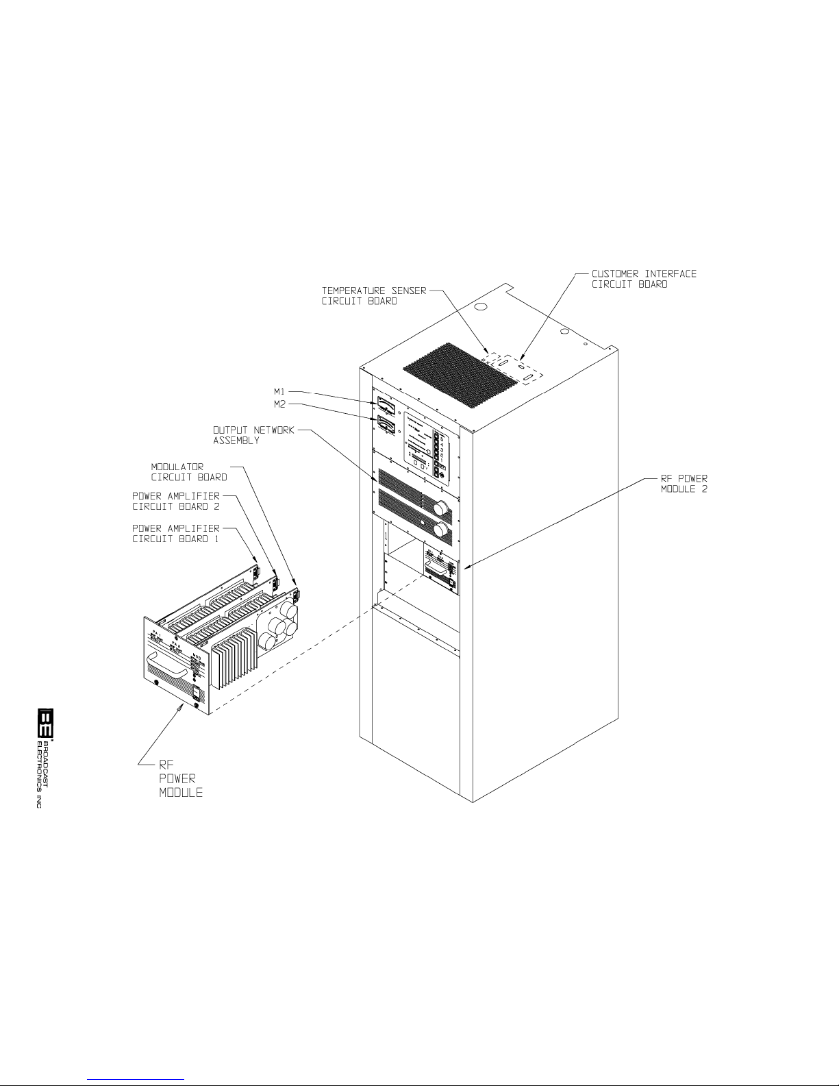
5-15
WARNING: DISCONNECT POWER PRIOR TO SERVICING
597-1114-18
FIGURE 5-2. AM-2.5E COMPONENT LOCATOR (SHEET 1 OF 3)
COPYRIGHT 1999 BROADCAST ELECTRONICS, INC
 Loading...