

Page 1

ES-2200
Dual Channel Expansion System
Operator’s Manual
Page 2

Table of Contents
Table of Contents...............................................................................................................................1
Table of figures..................................................................................................................................3
Introduction.......................................................................................................................................4
DPS ES-2200 General Description.................................................................................................... 4
Compatible DPS Products ................................................................................................................ 5
Chapter 1: Installation and Configuration.......................................................................................6
Unpacking & Inspection................................................................................................................... 6
Mounting.......................................................................................................................................... 6
ES-2200 System Configuration ......................................................................................................... 8
ES-2200T Configuration Options ..................................................................................................... 9
ES-2200T Card Installation............................................................................................................ 10
ES-2200S Configuration options ..................................................................................................... 11
ES-2200S Card Installation ............................................................................................................ 11
Chapter 2: ES-2200T Operation.....................................................................................................13
Unit Select...................................................................................................................................... 14
TBC Card Controls ........................................................................................................................ 15
Proc Amp .....................................................................................................................................................................................15
Memory Functions .....................................................................................................................................................................16
Balance .........................................................................................................................................................................................17
Freeze Controls ...........................................................................................................................................................................17
Timing..........................................................................................................................................................................................18
Input..............................................................................................................................................................................................18
TBC Configuration.....................................................................................................................................................................19
TBC Configuration Functions..................................................................................................................................................20
TBC IV Option Card Controls .................................................................................................................................................20
V-Scope Controls ........................................................................................................................... 21
RS-2800 Personal Routing Switcher............................................................................................... 22
Controlling an 8-bit MicroSYNC .............................................................................................................................................23
in the ES-2200T Chassis ...........................................................................................................................................................23
Chapter 3: ES-2200S Operation......................................................................................................24
Unit Select...................................................................................................................................... 25
MicroSYNC Controls ..................................................................................................................... 26
Proc Amp Controls.....................................................................................................................................................................26
Freeze Controls .............................................................................................................................. 26
Memory ........................................................................................................................................................................................27
Function.......................................................................................................................................................................................27
1
Page 3

Timing..........................................................................................................................................................................................28
MicroSYNC CONFIGURE Select..........................................................................................................................................29
MicroSYNC Configuration Functions....................................................................................................................................30
V-Scope Controls ........................................................................................................................... 31
RS-2800 Personal Routing Switcher............................................................................................... 32
Chapter 4: Video Connections.........................................................................................................33
Personal TBC III Connectors...................................................................................................................................................33
Personal TBC IV Connectors ......................................................................................................... 35
DPS 8-Bit MicroSYNC Connectors ................................................................................................ 37
DPS MicroSYNC-X Connectors.............................................................................................................................................39
Personal V-Scope Connectors ..................................................................................................................................................41
Personal Video Routing Switcher Connectors......................................................................................................................43
Outputs .........................................................................................................................................................................................44
Personal VDA Connectors ........................................................................................................................................................45
Chapter 5: Remote Control..............................................................................................................47
DPS Computer Software ...........................................................................................................................................................47
Card Addressing.........................................................................................................................................................................49
RC-2000 Remote Control..........................................................................................................................................................50
RC-2001 Remote Control..........................................................................................................................................................51
Appendices........................................................................................................................................55
Appendix A: Specifications ............................................................................................................. 56
Serial Data Input .........................................................................................................................................................................56
Power Requirements..................................................................................................................................................................56
Physical Characteristics.............................................................................................................................................................56
Appendix B: Serial Protocol........................................................................................................... 57
Electrical Interface......................................................................................................................................................................57
Protocol ........................................................................................................................................................................................57
System Exclusive Byte..............................................................................................................................................................57
TBC/MicroSYNC/V-Scope ID Byte.......................................................................................................................................58
Unit Address Byte......................................................................................................................................................................58
TBC/MicroSYNC Function Select/Data Byte(s)..................................................................................................................59
MicroSYNC Configuration Bytes...........................................................................................................................................61
TBC IV Configuration Bytes ...................................................................................................................................................62
V-SCOPE Function Select Byte/Data Byte(s).......................................................................................................................63
Appendix C: Important Addresses and Phone Numbers ................................................................ 64
Appendix D: A Brief History of DPS.............................................................................................. 66
Appendix E: Warranty ................................................................................................................... 67
Warranty Statement....................................................................................................................................................................67
Warranty Limitations.................................................................................................................................................................67
Warranty Service........................................................................................................................................................................68
Appendix F: Compliance ................................................................................................................ 69
FCC Compliance Statement......................................................................................................................................................69
2
Page 4

Table of figures
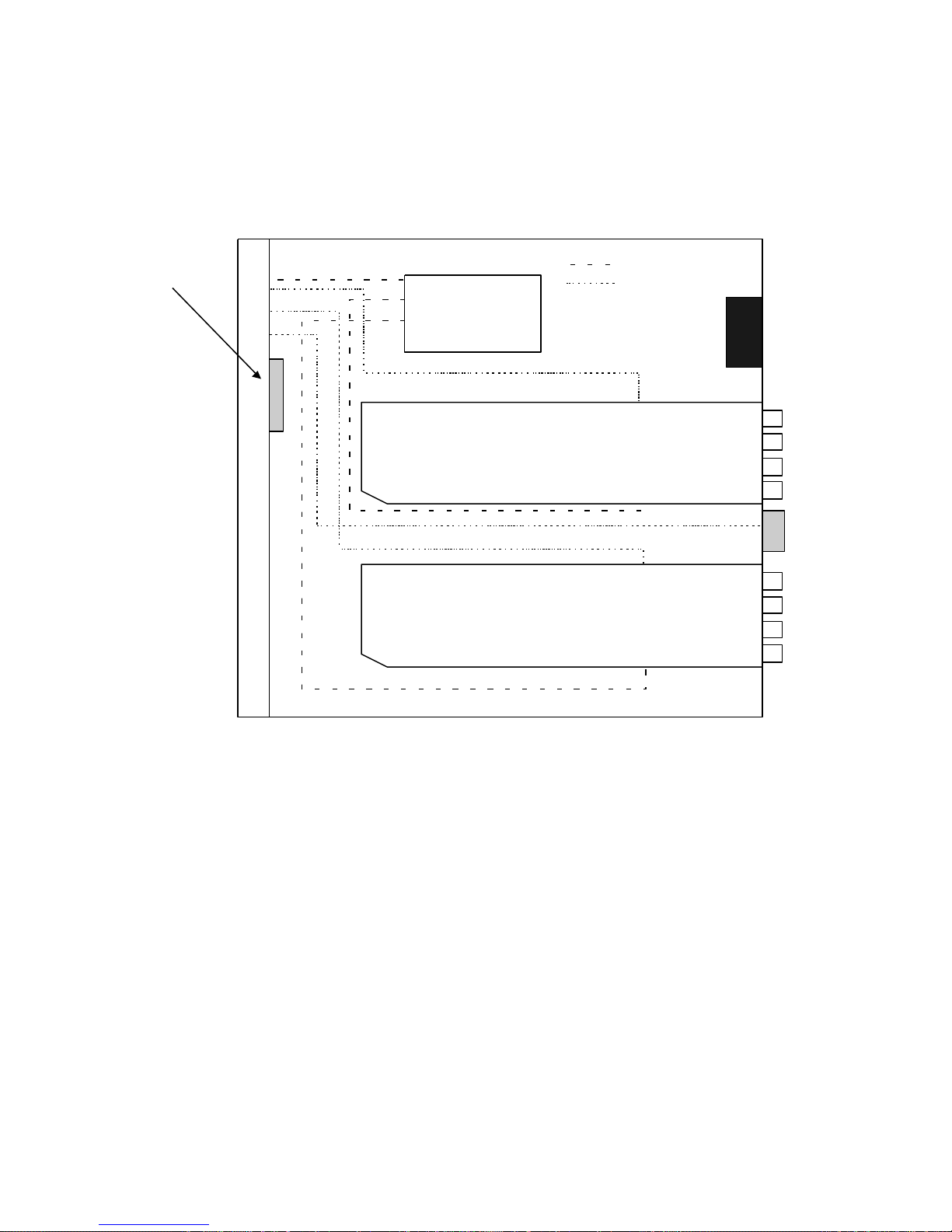
Figure 1-1: ES-2200 Top View 7
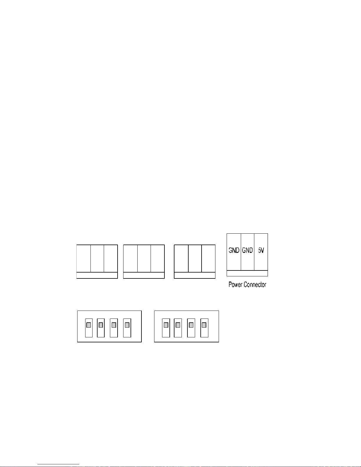
Figure 1-2: ES-2200 Front Panel DIP Switch Assignments 8
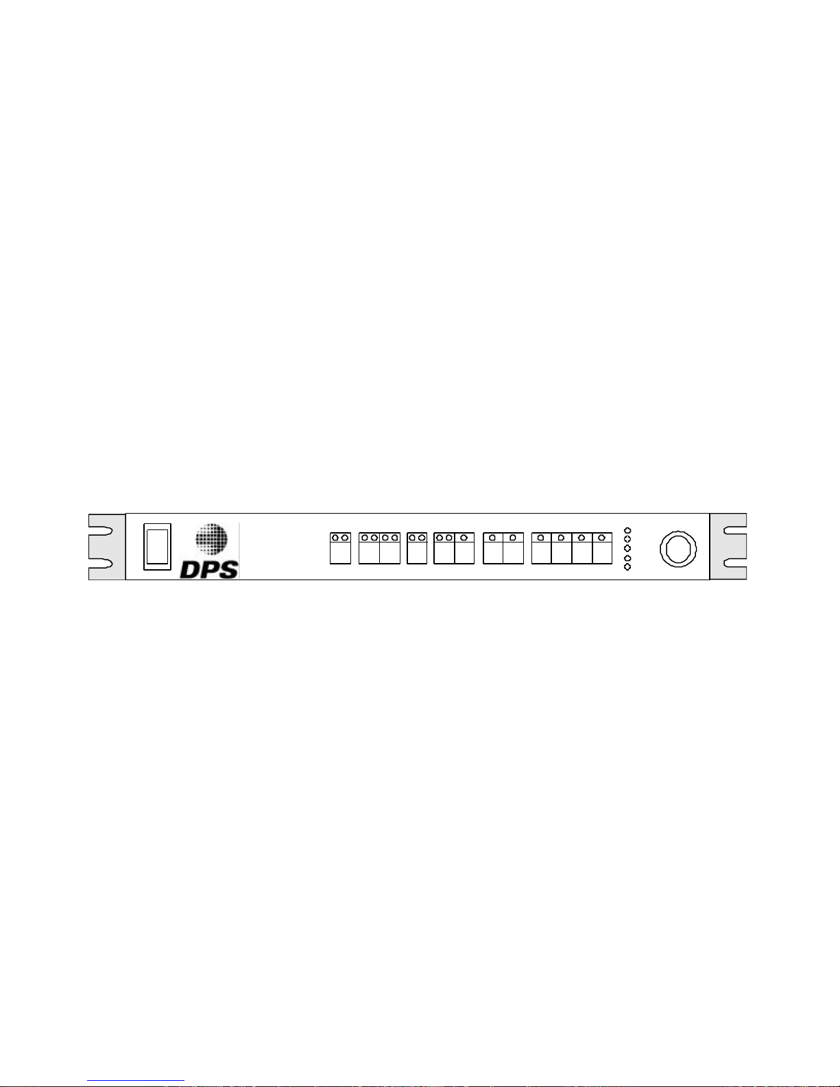
Figure 2-1: ES-2200T Front Panel 13
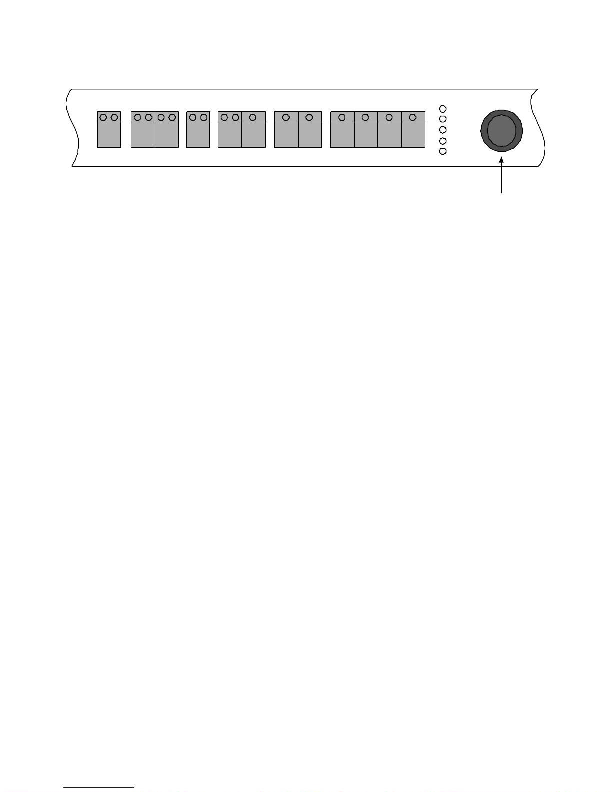
Figure 2-2: ES-2200T Controls 14
Figure 2-3: MicroSYNC Controls in the ES-2200T Chassis 23
Figure 3-1: ES-2200S Front Panel 24
Figure 3-2: ES-2200S Controls 25
Figure 4-1: Personal TBC III I/O Connectors 33
Figure 4-2: Personal TBC III Card 34
Figure 4-3: Personal TBC IV I/O Connectors 35
Figure 4-4: Personal TBC IV Card 36
Figure 4-5: DPS MicroSYNC I/O Connectors 37
Figure 4-6: DPS MicroSYNC Card 38
Figure 4-7: DPS MicroSYNC-X I/O Connectors 39
Figure 4-8: DPS MicroSYNC Card 42
Figure 4-9: Personal V-Scope I/O Connections 41
Figure 4-10: Personal V-Scope Card 42
Figure 4-11: Personal Routing Switcher I/O Connections 43
Figure 4-12: Personal Routing Switcher Card 44
Figure 4-13: Personal VDA I/O Connectors 45
Figure 4-14: Personal VDA Card 46
Figure 5-1: Computer Serial Port to ES-2200 Cable Assembly 50
Figure 5-2: RC-2000 to ES-2200 Cable Assembly 52
Figure 5-3: Controlling Two ES-2200 Units 53
Figure 5-4: Controlling Three ES-2200 Units 54
3
Page 5

Introduction
DPS ES-2200 General Description
The DPS ES-2200 is a 2-slot expansion system intended to accommodate any combination of up to two DPS Personal
Series or MicroSYNC plug-in cards. The functions of the DPS Personal Series cards installed in the system can be
operated by the front panel control or by software using the rear panel RS-232 connector.
There are two versions of the ES-2200. The ES-2200T is intended for TBC cards. Its front panel is marked according
to operations specific to TBCs. The ES-2200S is intended for DPS MicroSYNC cards. Its front panel is marked
according to operations specific to MicroSYNC cards. It is possible to install a MicroSYNC and a TBC card into the
ES-2200T. However, the front panel will not be marked for operations specific to the card that was not intended for the
unit.
With the exception of MicroSYNC and TBC cards, any of the cards listed on the following page may be installed into
either the ES-2200S or the ES-2200T. If you are installing the cards yourself follow the procedure that begins on page
8, paying careful attention to DIP Switch positions.
The Operations section of this manual is divided into two sections. Chapter 3 is the ES-2200T operations section. If
you have purchased the ES-2200T, you should only read Chapter 2. Similarly, Chapter 3 is the ES-2200S operations
section. You should read this chapter if you have purchased the ES-2200S.
4
Page 6

Compatible DPS Products
DPS PERSONAL TBC CARDS
The DPS Personal TBC is a full frame TBC which enables virtually any VCR, Camcorder, Laser Disk player
or Video Camera to be interfaced with other video sources in a video production environment. A TBC is a necessary
piece of video production hardware because time base errors are inherent in mechanical video storage devices such as
VTRs. Up to two DPS Personal TBC cards can be installed in the DPS ES-2200T Expansion System.
DPS MICROSYNC
The DPS MicroSYNC is a four-field composite transparent video synchronizer that can be used to lock a nonsynchronous direct color composite video signal to a video system. The MicroSYNC utilizes four field composite
processing to achieve transparent performance without the need for low pass or comb filter Y/C separator circuits.
There are two types of DPS MicroSYNC: the DPS 8-bit MicroSYNC and the DPS MicroSYNC-X. Up to two DPS
MicroSYNC cards can be installed in the DPS ES-2200S Expansion System. An 8-bit MicroSYNC can be installed by
itself or with another card in the ES-2200T chassis.
DPS PERSONAL V-SCOPE
The DPS Personal V-Scope is a combination waveform monitor and vectorscope that provides real time monitoring of
video signals. The V-Scope produces a digitally synthesized waveform/vector display, including graticules, which can
be displayed on any video monitor. The V-Scope features a variety of display modes including simultaneous waveform
and vector displays in either overlay or split modes. One DPS Personal V-Scope is recommended for installation in the
DPS ES-2200 Expansion System.
DPS PERSONAL VIDEO ROUTING SWITCHER
The DPS Personal Video Routing Switcher is a composite video switcher containing a 4x1 and an 8x1
switching matrix. The 4x1 matrix is connected to BNC connectors located on the back of the card. The inputs to the
8x1 matrix originate from the card edge. The inputs to the 8x1 input matrix originate from the card edge and cannot be
used in an ES-2200 chassis. Up to two DPS Personal Video Routing Switchers can be installed in the DPS ES-2200
Expansion System.
DPS PERSONAL VDA
The DPS Personal VDA is a video distribution amplifier capable of driving four 75? terminated loads from
one video input. Install up to two DPS Personal VDA cards into the DPS ES-2200 Expansion System.
5
Page 7

Chapter 1:
Installation
and Configuration
Unpacking & Inspection
This unit has been thoroughly calibrated and inspected, both electrically and mechanically, to ensure that it meets the
published specifications. The following items are included with each DPS ES-2200 Expansion System:
QTY DESCRIPTION
1 DPS ES-2200 Expansion System
1 DPS ES-2200 Operator’s Manual
1 Standard AC Line Cord
We suggest that you retain all original packing materials. This will facilitate reshipment should it ever become
necessary.
Mounting
The size of the ES-2200 allows it to fit into most standard consoles or 19-inch racks. If the unit is to be mounted in a
rack, then rack slides or trays must be used for support. Care must be taken to select a dry, well-ventilated location
with a minimum of dust and vibration. Also, leave sufficient clearance from the unit’s rear panel to allow for proper air
circulation.
After unpacking the unit and before installing cards in it or installing it in a console or rack, allow at least 30 minutes
for temperatures to equalize and to eliminate any condensation that may have developed.
6
Page 8
Power Supply
RS-232 “Input”
DC Power Input
RS-232 “Input”
DC Power Input
Front Panel
DIP Switch
DC Power Cables
DB-9 Port
ES-2200 Front Panel
Settings
RS-232 Cables
Fan
Unit 1
Remote
RS-232
Unit 2
Figure 1-1: ES-2200 Top View
7
Page 9
ES-2200 System Configuration
Unit 1 Connector
1 2 3 4 5 6 7 8
This section shows how to set cards and install them to be operated from the front panel of the ES-2200 unit.
Remember:
All DIP Switches must be configured with the power off.
Static electricity from your body can damage the cards. To prevent this type of damage, you should handle them
carefully:
• Do not take them out of their conductive bags until you are ready to install them.
• Do not carry them around the room unless they are in their conductive bags.
• Before touching them, discharge any static electricity from your body by first touching the grounded metal chassis.
TX GND RX
Remote Connector
TX GND RX
Unit 2 Connector
TX GND RX
Up Position
Down Position
Figure 1-2: ES-2200 Front Panel DIP Switch Assignments
8
Page 10

ES-2200T Configuration Options
It is possible to install a single card – TBC, MicroSYNC, V-Scope or Routing Switcher in the ES-2200T chassis. In
such a case, the card should be installed in the Unit 1 position unless it is a V-Scope. If it is a V-Scope, it should
always go in the Unit 2 position. Two cards can be installed in the ES-2200T chassis. The possible configurations are
as follows:
Unit 1 Unit 2
TBC TBC
TBC V-Scope
TBC Routing Switcher
TBC 8-Bit MicroSYNC
8-Bit MicroSYNC TBC
8-Bit MicroSYNC V-Scope
V-Scope V-Scope
Routing Switcher Routing Switcher
If you put only one card in the ES-2200T chassis, unless it is a V-Scope, place it in Unit 1 position. If you are putting
one of the above cards in the ES-2200T chassis as well as a VDA card, put the VDA card in the Unit 2 position.
The DPS Personal V-Scope should always go in the Unit 2 position. Before installing two V-Scope cards in the
ES-2200T, the second V-Scope requires a custom microprocessor. If you require this custom microprocessor, contact
DPS customer service.
It is possible to install a TBC card and a MicroSYNC card together into the ES-2200T Expansion System. Some
MicroSYNC operations are not reflected on the front panel, but can still be selected. Please contact DPS for more
information.
9
Page 11

ES-2200T Card Installation
1. Remove the carrier plates from the backs of the cards. Save the screws to mount the cards in the chassis.
2. With the power off, remove the top cover of the chassis.
3. If the card to be installed in the unit 1 position is a Personal V-Scope, place DIP Switch 1 in the DOWN position,
and all others UP. For all other card types, place DIP Switch 2 on the card intended for unit 1 in the DOWN
position and all others UP.
4. If a Personal V-Scope is to be installed in the Unit 2 position, place DIP Switch 1 on the V-Scope in the DOWN
position, and all others UP. If any other type of card is intended for the unit 2 position, place DIP Switches 2, 3, 4,
5, 6 and 7 on that card in the DOWN position and all others UP.
5. On the ES-2200 front panel, place DIP Switches 1, 2, 3, 4 and 5 in the UP position. DIP Switches 6, 7 and 8 are
placed in the following positions, depending on what combination of cards you are installing:
Unit 1 Unit 2 Switch 6 Switch 7 Switch 8
TBC TBC DOWN DOWN DOWN
TBC V-Scope DOWN DOWN UP
TBC Routing Switcher DOWN UP DOWN
TBC 8-Bit MicroSYNC DOWN UP UP
8-Bit MicroSYNC TBC UP DOWN DOWN
8-Bit MicroSYNC V-Scope UP DOWN UP
V-Scope V-Scope UP UP DOWN
Routing Switcher Routing Switcher UP UP UP
If you are installing a single card in the ES-2200T, it should be placed in the unit 1 position unless it is a V-Scope.
The Personal V-Scope should always be in the Unit 2 position except if the ES-2200T chassis is intended to hold
two Personal V-Scopes. If a single V-Scope is to be the only card in the ES-2200T chassis, DIP Switch settings
option #7 (UP, UP, DOWN) should be chosen.
If there is no card intended for the unit 2 position, select a DIP Switch setting to indicate what is in the Unit 1
position. For example, if you put a lone MicroSYNC card in the Unit 1 position, the DIP Switches could be set to
UP, DOWN, DOWN (MicroSYNC and TBC) or UP, DOWN, UP (MicroSYNC and V-Scope). If a VDA is
intended for the unit 2 position, set the DIP Switches as if the position was empty.
6. Install the 3 wire RS-232 cable for unit 1 (figure 2-1) to the 3 pin header labeled INPUT at the top of the first card
near the BNC connectors near the fan.
7. Press the power supply's edge connector for unit 1 onto the first card as far as it will go.
8. Mount the first card in the unit 1 position using the five screws provided and install the supplied hardware for the
rear panel support bracket.
9. Install the 3 wire RS-232 cable for unit 2 (figure 2-1) to the 3 pin header labeled INPUT at the top of the second
card near the BNC connectors.
10. Press the power supply's edge connector for unit 2 onto the second card as far as it will go.
11. Mount the second card in the unit 2 position using the five screws provided and install the supplied hardware for
the rear panel support bracket and install the top cover.
NOTE: While baud rates the individual cards installed in the ES-2200T chassis are capable of being set to DOWN
(9600 BPS) or UP (31,250 BPS), the ES-2200T chassis defaults to 9600 BPS. Therefore, DIP Switch 2 should always
be in the DOWN position on cards that are to be installed in the ES-2200T Expansion System.
10
Page 12

ES-2200S Configuration options
The ES-2200S chassis is designed to accept DPS 8-bit MicroSYNC cards and 10-bit MicroSYNC-X cards, as well as
Personal V-Scopes, VDAs and Routing Switchers. The possible combinations are:
Unit 1 Unit 2
VS-2400
VS-2410
VS-2400 VS-2400
VS-2410 VS-2410
VS-2400 V-Scope
VS-2410 V-Scope
VS-2400 Routing Switcher
VS-2410 Routing Switcher
VS-2400 VDA
VS-2410 VDA
ES-2200S Card Installation
1. Before installation, remove the carrier plates from the backs of the cards and save the screws to mount the cards in
the chassis.
2. With the power off, remove the top cover of the chassis.
3. Place DIP Switch 2 on the card intended for unit 1 in the down position and all others up.
4. If a Personal V-Scope is intended for the unit 2 position, place the DIP Switch on the V-Scope 1 in the down
position, and all others up. If any other type of card is intended for the unit 2 positon, place DIP Switches 2, 3, 4,
5, 6 and 7on the intended card in the down position and all others up.
5. On the ES-2200 front panel, place DIP Switches 1, 2, 3, 4, 5 and 6 in the up position. DIP Switches 7 and 8 are
placed in the following positions, depending on what cards you are installing:
Unit 1 Unit 2 Switch 7 Switch 8
VS-2400 DOWN DOWN
VS-2410 UP UP
VS-2400 VS-2400 DOWN DOWN
VS-2410 VS-2410 UP UP
VS-2400 V-Scope UP DOWN
VS-2410 V-Scope DOWN UP
VS-2400 Routing Switcher UP DOWN
VS-2410 Routing Switcher DOWN UP
VS-2400 VDA DOWN DOWN
VS-2410 VDA UP UP
6. Install the 3 wire RS-232 cable for unit 1 (figure 2-1) to the 3 pin header labeled INPUT at the top of the first card
near the BNC connectors near the fan.
7. Press the power supply's edge connector for unit 1 onto the first card as far as it will go.
8. Mount the first card in the unit 1 position using the five screws provided and install the supplied hardware for the
rear panel support bracket.
11
Page 13

9. Install the 3 wire RS-232 cable for unit 2 (figure 2-1) to the 3 pin header labeled INPUT at the top of the second
card near the BNC connectors.
10. If there is a card intended for the unit 2 position, press the power supply's edge connector for unit 2 onto the second
card as far as it will go.
11. Mount the second card in the unit 2 position using the five screws provided and install the supplied hardware for
the rear panel support bracket and install the top cover.
Note: DIP Switch 1 on both the ES-2200S chassis and the cards installed therein controls baud rate.
UP 9600 B/s
DOWN 31.25 kB/s
There is no advantage to either setting, but the baud rate must be set to the same rate for both the installed cards and the
ES-2200S chassis.
12
Page 14
Chapter 2:
SELECT TIMING INPUT FREEZE BALANCE PROC AMP
ES-2200T Operation
POWER
ON
1
0
ES-2200T
DUAL TBC
EXPANSION SYSTEM
V-SCOPE CONTROLS
TBC CONFIGURATION
UNIT UNIT H-POS C F NTSC SVHS FRM/FLD TAKE RED BLUE VIDEO BLACK CHROMA HUE
1 2 FLAT LOW 1H 2H PK/VAR FREEZE NRM SUPER WAVFRM VECTOR OVERLAY SPLIT
REMOTE CONFIGURE STROBE FILM MD STORE RECALL PREVIOUS UNITY
VRT BLKG MONO GEN MD BURST BLK OUT GEN TERM CMB FLTR HOT SW
5 MAX
4 +
3 UNITY
2 -
1 MIN
Figure 2-1: ES-2200T Front Panel
This section describes the front panel controls and indicators for the ES-2200T dual channel expansion system. The ES2200T is designed to operate any two DPS PC cards, including the Personal TBC III/IV, V-Scope and Routing
Switcher.
The SELECT button is used to address the individual cards installed in the UNIT 1 and UNIT 2 positions. After
selecting a desired unit, the front panel indicators will display the selected card parameters. The momentary push
button switches on the ES-2200T front panel are used to select the various operating modes. Pressing the appropriate
button (e.g., Video) and then rotating the shaft encoder knob performs changes to a mode setting (e.g., Video Level).
The bar graph display, located to the left of the shaft encoder, provides a relative measure of the selected setting.
The labels in red located directly above the ES-2200 front panel buttons represent V-Scope functions. The labels
located above the V-Scope labels in black represent the TBC card functions. The actual operation of the controls
depends on the combination of cards installed in the ES-2200 chassis. For example, if a TBC card was installed in
UNIT 1 and a V-Scope in UNIT 2, the labels in black would refer to UNIT 1 (TBC) functions and the red labels would
refer to UNIT 2 (V-Scope) functions.
If the ES-2200T you are operating has an 8-bit MicroSYNC installed in it, the front of the chassis will not reflect all the
MicroSYNC commands. Please refer to Figure 2-3 to see how those controls relate to the
ES-2200T’s controls.
13
Page 15
SELECT TIMING INPUT FREEZE BALANCE PROC AMP
Shaft Encoder
UNIT UNIT H-POS C F NTSC SVHS FRM/FLD TAKE RED BLUE VIDEO BLACK CHROMA HUE
1 2 FLAT LOW 1H 2H PK/VAR FREEZE NRM SUPER WAVFRM VECTOR OVERLAY SPLIT
REMOTE CONFIGURE STROBE FILM MD STORE RECALL PREVIOUS UNITY
VRT BLKG MONO GEN MD BURST BLK OUT GEN TERM CMB FLTR HOT SW
5 MAX
4 +
3 UNITY
2 -
1 MIN
Figure 2-2: ES-2200T Controls
Unit Select
The UNIT select button is used to address the selected installed card. Whenever UNIT 1 is selected, all of the front
panel controls and indicators display the current parameters of the card installed in the UNIT 1 slot. When UNIT 2 is
selected the front panel controls and indicators display the current parameters of the card that is installed in the UNIT 2
slot. This button is also used to select remote/local operation.
UNIT 1
When this button is selected, the ES-2200T will recall and display the current status of the card that is connected in the
UNIT 1 slot. A flashing UNIT 1 LED indicates that the installed card is not responding to the ES-2200T commands. If
this happens then make sure that the Baud rate of both the front panel and the installed card are the same and that the
serial interface cable is connected. Note that this LED will not flash if the installed unit is a V-Scope or a Personal
Routing Switcher card because the ES-2200T does not poll these cards.
UNIT 2
When this button is selected, the ES-2200T will recall and display the current status of the card that is connected in the
UNIT 2 slot. A flashing UNIT 2 LED indicates that the installed card is not responding to the ES-2200T commands. If
this happens then make sure that the Baud rate of both the front panel and the installed card are the same and that the
serial interface cable is connected. Note that this LED will not flash if the installed unit is a V-Scope or a Personal
Routing Switcher card.
REMOTE
The remote function causes the ES-2200T to go into remote mode. The installed Personal series cards can then accept
commands from a remote source such as a computer or a remote control module. The commands are accepted via the
rear panel's DB-9 female connector, and are processed by the front panel and echoed to the selected UNIT. Holding in
the SELECT button for approximately one second activates this function. When this function is active, the front panel
UNIT 1 and UNIT 2 LEDs both light up. To select local mode simply press the UNIT 1/ UNIT 2 button once.
14
Page 16

TBC Card Controls
Push buttons on the ES-2200T unit can have up to three control functions associated with them. Primary functions are
in Black. Secondary functions are in Blue. Shift functions are in Italic.
Proc Amp
Proc Amp controls are applicable to TBC cards. The Proc Amp controls are VIDEO LEVEL, BLACK LEVEL,
CHROMA LEVEL, and HUE LEVEL.
VIDEO
The VIDEO LEVEL button selects video level control for the shaft encoder. Changing the video level effects the
overall amplitude of the processed video signal, resulting in a change in the displayed picture contrast.
BLACK
The BLACK LEVEL button selects black level control for the shaft encoder. Changing the black level effects the DC
level of the processed video signal, resulting in a change in the displayed picture brightness.
CHROMA
The CHROMA LEVEL button selects chroma level control for the shaft encoder. The chroma level control changes the
color saturation of the processed video signal.
HUE
The HUE LEVEL button selects hue level control for the shaft encoder. The hue control changes the phase of the
processed color subcarrier, which effects the tint of the displayed picture.
15
Page 17

Memory Functions
These functions are shift functions in italics below the Proc Amp controls.
The ES-2200T stores all current settings, such as Proc-amp levels and system timing in its own non-volatile memory.
The memory is automatically updated once every three seconds. These settings are automatically recalled and
transferred to the resident TBC cards on power up, so that system timing and Proc-amp levels are not lost. System
timing information is stored separately for each resident card. Proc-amp levels are stored with respect to each TBC.
STORE
Holding in the VIDEO button for about a second activates this function. The memory store function causes the current
proc amp settings, including color balance and horizontal position, to be saved in non-volatile memory in the ES2200T. These settings may later be recalled using the recall function. When this function occurs, the front panel proc
amp LEDs flash.
RECALL
Holding in the BLACK button for about a second activates this function. The memory recall function is used to recall
settings previously stored using the store function. When this function occurs, the front panel proc amp LEDs flash for
one second.
PREVIOUS
Holding in the CHROMA button for approximately one second activates this function. The memory previous function
is used to return the proc amp settings to those present before a memory recall or unity function. When this function
occurs, the front panel proc amp LEDs flash for one second.
UNITY
Holding in the HUE button for approximately one second activates this function. The memory unity function returns all
proc amp and color balance settings to their factory-preset values. When this function occurs, the front panel proc amp
LEDs flash for one second.
16
Page 18

Balance
The Color Balance controls are labeled BALANCE on the front panel. RED and BLUE are primary functions. FILM
MD is a shift function below BLUE in italics. These controls are used to change the white balance of the processed
video signal on an installed TBC card. They can be used to correct for footage shot with improper white balance, or
used to add a color wash as a special effect.
RED
This button selects R-Y color balance control for the shaft encoder. Changing the R-Y color balance has the effect of
adding/subtracting red to the processed video signal. This adjustment is only valid for a TBC card.
BLUE
This button selects B-Y color balance control for the shaft encoder. Changing the B-Y color balance has the effect of
adding/subtracting blue to the processed video signal. This adjustment is only valid for a TBC card.
FILM MODE
This feature simulates the 3-2 pull down conversion technique from a 24 frame per second film standard to a 30 frame
per second video standard. This function is available for TBC IV cards only and is activated by holding in the BLUE
button for approximately one second. When this function is engaged, RED balance and Proc Amp functions are
available for adjustment. While in this mode, the BLUE and TAKE LEDs flash. To exit this mode, press the BLUE
button again.
Freeze Controls
TAKE and FRM/FLD are primary functions. STROBE is a shift function marked in italics under FRM/FLD.
TAKE
The TAKE button used to toggle between FREEZE and LIVE modes. Note that when the unit is in the FREEZE
FIELD mode and the freeze function is activated, the shaft encoder may be used to select one of the three fields
captured when the freeze function was actuated.
FRM/FLD
This button is used to select between FRAME (FRM) and FIELD (FLD) FREEZE modes. The FRAME mode is
normally used for static scenes (i.e. no motion) because it provides better vertical resolution. The FIELD mode is used
to freeze scenes that contain motion. When a TBC card is installed, the shaft encoder can be used to select field 1, field
2, or field 3.
STROBE FUNCTION
The strobe function is engaged by pressing and holding the freeze FRM/FLD button until the FRM LED begins to
flash. STROBE mode is then entered when the FREEZE TAKE button is selected. When the unit is in STROBE mode,
the shaft encoder may be used to select the desired strobe rate.
17
Page 19

Timing
The SYSTEM TIMING or GENLOCK controls are used to modify the timing of the video outputs from the installed
TBC cards so that correct system timing is maintained when the unit is used in conjunction with other video processing
equipment. When a reference video signal is connected to the selected (installed) TBC card reference video input, the
outputs from that card would nominally be co-timed with this signal. Using the GENLOCK controls, the installed card
output video may be shifted with respect to the reference video input.
C – F (GENLOCK TIMING)
This button enables the horizontal genlock timing to be changed via the shaft encoder. Press the button once and the F
(fine) LED comes on. Press the button again and the C (coarse) LED lights up. When in COARSE mode, the shaft
encoder enables the video output signal to be moved in steps of 270 nsec, or 360 degrees. A flashing C LED indicates
that the selected unit is not genlocked.
When the F (fine) LED is lit, the fine genlock timing can be changed via the shaft encoder. Fine genlock timing moves
the output video in steps of 0.55 nsec or 0.70 degrees. A flashing subcarrier F LED indicates that the selected unit is not
genlocked.
To disable accidental genlock timing adjustments or to terminate the input reference signal, see CONFIGURATION
OPTIONS later in this chapter. If genlock adjust is disabled, no timing adjustments can be made until it is re-enabled.
This button can be used to adjust the Y/C Horizontal Delay. To do so, press and hold the C-F button down until both its
LEDs flash. Then rotate the shaft encoder to adjust the Y/C delay. This function affects only the TBC IV card.
H-POS
This button enables the horizontal position of the video signal to be adjusted +/- 1 us by using the shaft encoder.
This button can be used to adjust the Y/C Vertical Delay. To do so, press and hold the H POS button down until its
LEDs flash. Then rotate the shaft encoder and set the Bar graph LED to one of four positions. This function affects
only the TBC IV card.
Input
When the ES-2200 is configured for a TBC IV (or TBC III) card, the INPUT SELECT button functions as an
NTSC/S-VID select button as described below.
NTSC
If the installed card is a TBC card, then this button selects COMPOSITE input mode. If there is no video input at the
selected TBC card, the NTSC LED will flash.
S-VHS
If the installed card is a TBC card, this button selects S-Video input mode for use with S-VHS or HI-8 VCRs. If there is
no input at the selected TBC card, the SVHS LED will flash.
18
Page 20

TBC Configuration
The TBC card can be configured with a number of setup modes. In order to change a se tup mode, you must
perform the following steps:
1. Choose the ES-2200 channel containing the TBC card using the UNIT 1/ UNIT 2 SELECT button.
2. Place the TBC card into CONFIGURATION SELECT mode by pressing the NTSC/S-VHS INPUT button so that
the NTSC and S-VID LEDs are flashing
3. In CONFIGURATION mode, each button takes on a new function. Select the desired CONFIGURATION
function by pressing the appropriate button. CONFIGURATION functions are located below the buttons and are
labeled in blue.
4. Choose a mode for the selected CONFIGURATION function by turning the rotary shaft encoder knob. Modes are
indicated by the number (1 to 5) legends located to the left of the LED level display. The default value for each
setup mode is 1. The following table details the various CONFIGURATION function choices.
Remember, after changing one or more of these TBC configure modes, the unit will remain in CONFIGURATION
mode until you press the CONFIGURE button to return the TBC to normal operation. Once the CONFIGURE LEDs
are extinguished, the buttons return to their primary functions which are denoted by the black legends located above
each button.
19
Page 21

TBC Configuration Functions
Button Function/ Mode
VRT BLKG Vertical Blanking Width
1. Narrow
2. Wide
MONO Monochrome Mode
1. Normal
2. Forced Monochrome
GEN MD Genlock Adjust
1.Genlock Adjust Enable
2. Genlock Adjust Disable
BURST Output Burst Mode
1. On
2. Off
BLK OUT TBC Function
1. Normal
2. Super Black Out
GEN TER M Genlock Termination
1. High Impedance
2. 75O terminated
CMB FLTR TBC IV Chroma Filter/Option Card Comb Filter
1. TBC IV Chroma On/Comb Filter Off
2. TBC IV Chroma Off/Comb Filter Off
3. TBC IV Chroma Off/Comb Filter On
HOT SW Hot Switch Mode
1. Disable
2. Enable
Note: Mode 1 is the default factory setting for all functions.
TBC IV Option Card Controls
If your TBC IV is not equipped with an option card then skip this section. If the TBC IV is equipped with an option
card, Betacam and MII outputs will be added to the TBC IVs Mini DIN-9 connector. Luminance and chrominance
noise reduction will also be available. To operate the TBC IV option card functions, follow the procedure outlined
under TBC CONFIGURATION earlier in this chapter. (Refer to the TBC IV/Option card manual for more
information.)
20
Page 22

V-Scope Controls
V-Scope commands appear in red directly above the front panel buttons. They are valid when the selected unit
is a V-Scope, as determined by the DIP Switch settings outlined in the installation section of this manual.
WAVFRM
Places the V-Scope in FULL SCREEN WAVEFORM DISPLAY mode.
VECTOR
Places the V-Scope in FULL SCREEN VECTOR DISPLAY SCOPE mode.
OVRLAY
Places the V-Scope in FULL SCREEN WAVEFORM + VECTOR SCOPE OVERLAY mode. This produces a display
with both full screen waveform monitor and full screen vector scope simultaneously displayed.
SPLIT
Places the V-Scope in WAVEFORM AND VECTOR SCOPE SCREEN mode. This produces a display in which the
top half of the screen shows live video and the bottom half consists of quarter-sized waveform monitor and vector
scope displays placed side by side.
NRM
Places the V-Scope in the NORMAL DISPLAY mode. The V-Scope display is updated every two frames.
SUPER
Enables the superimpose output from the V-Scope, which contains the synthesized waveform/vector display as
determined by the other selections (i.e., waveform, vector mode).
PK/VAR
Selects between PEAK-HOLD and VARIABLE DISPLAY modes. When PEAK-HOLD is selected, old data is not
erased. A cumulative display showing all peak video excursions results. When VARIABLE is selected, rotate the shaft
encoder to select a display rate and change the display update rate. Increasing the rate produces a more fully colored
display.
FREEZE
Freezes the V-Scope trace, providing an instantaneous snap shot of the current waveform/vectors display.
1H/ 2H
Selects between 1-H (single video line) and 2-H (dual video line) display modes. 1-H mode provides the best display
resolution. Use the 2-H mode to view the horizontal blanking interval of the video signal.
LOW
Sets the V-Scope in the low pass frequency response mode. This is normally used when setting white or black levels
while viewing the V-Scope waveform monitor display.
FLAT
Sets the V-Scope in the flat frequency response mode.
Note: The NORMAL display command is sent to the V-Scope upon selection of any of the above modes except
FREEZE, PEAK HOLD, and VARIABLE modes.
21
Page 23
RS-2800 Personal Routing Switcher
PROC AMP
IN-1 IN-2 IN-3 IN-4
CMB FLTR HOT SW
Routing Switcher commands are not on the ES-2200T front panel. A stick-on label is provided with each switcher card.
This label should be applied to the front panel underneath the proc-amp controls.
The ES-2200T can be configured to control one or two switcher cards. The Routing Switcher card has a four by one
(4x1) switching matrix accessible through the four input BNC connectors at the rear of the card. The Routing switcher
card also has an eight by one (8x1) switching matrix accessible through the Edge connector. When the Personal
Routing Switcher card is used in the ES-2200T, the 8x1 matrix can't be accessed and therefore is not used. The front
panel can control the 4x1 matrix as indicated on the label.
Place Sticker Here
STORE RECALL PREVIOUS UNITY
IN-1
When selected, the Personal Routing Switcher routes the video source on input #1 to the output BNC.
IN-2
When selected, the Personal Routing Switcher routes the video source on input #2 to the output BNC.
IN-3
When selected, the Personal Routing Switcher routes the video source on input #3 to the output BNC.
IN-4
When selected, the Personal Routing Switcher routes the video source on input #4 to the output BNC.
22
Page 24
Controlling an 8-bit MicroSYNC
SELECT TIMING INPUT FREEZE BALANCE PROC AMP
Shaft Encoder
BYPASS PROCESS
SYNC MD CLAMP IN LOCK BLK CLP
in the ES-2200T Chassis
UNIT UNIT H-POS C F NTSC SVHS FRM/FLD TAKE RED BLUE VIDEO BLACK CHROMA HUE
1 2 FLAT LOW 1H 2H PK/VAR FREEZE NRM SUPER WAVFRM VECTOR OVERLAY SPLIT
REMOTE CONFIGURE STROBE FILM MD STORE RECALL PREVIOUS UNITY
VRT BLKG MONO GEN MD BURST BLK OUT GEN TERM CMB FLTR HOT SW
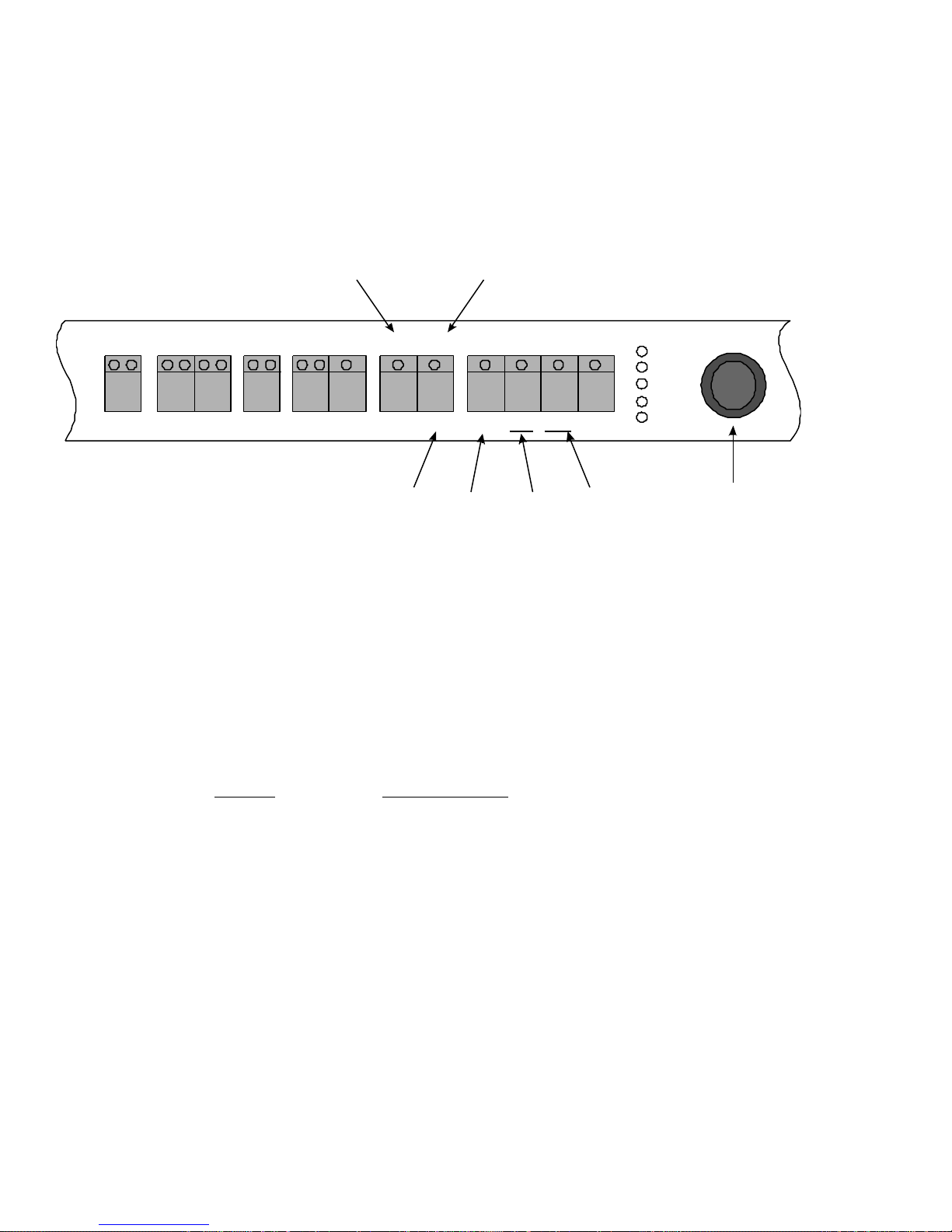
Figure 2-3: MicroSYNC controls in the ES-2200T Chassis
If your ES-2200T contains a MicroSYNC card, some of the MicroSYNC controls will not be reflected on the
ES-2200T front panel. Figure 2-3 shows the buttons that have MicroSYNC functions associated with them that are not
listed on the ES-2200T chassis. In BALANCE, instead of RED, the button pressed once activates BYPASS. BLUE
activates PROCESS. In the configuration functions, instead of the TBC function GEN TERM, when this button is
pressed while controlling a MicroSYNC, SYNC MD is activated. Instead of the TBC configuration function CMB
FLTR, when controlling a MicroSYNC, CLAMP is adjusted. The MicroSYNC has two functions for which there is no
TBC marking: IN LOCK and BLK CLP are both MicroSYNC configuration functions. MicroSYNC functions are
described fully in Chapter 3: ES-2200S Operation.
5 MAX
4 +
3 UNITY
2 -
1 MIN
Two controls are not listed under the MicroSYNC configuration Functions. These are:
BUTTON FUNCTION/MODE
BLK OUT MicroSYNC function.
1. NORMAL
2. Force Black Out
BLK CLIP Black Clip Select
1. On
2. Off
Please refer to Chapter 3: ES-2200S Operation for more information on MicroSYNC configuration options.
23
Page 25
Chapter 3:
ES-2200S Operation
Figure 3-1: ES-2200S Front Panel
ON
POWER
ES-2200S
DUAL MicroSYNC
1
EXPANSION SYSTEM
0
V-SCOPE CONTROLS
MicroSYNC CONFIGURATION
SELECT TIMING FREEZE FUNCTION PROC AMP
UNIT UNIT H-POS C F FRM/FLD TAKE BYPASS PROCESS VIDEO BLACK CHROMA HUE
1 2 FLAT LOW 1H 2H PK/VAR FREEZE NRM SUPER WAVFRM VECTOR OVERLAY SPLIT
REMOTE CONFIGURE STROBE STORE RECALL PREVIOUS UNITY
VRT BLKG MONO GEN MD BURST BLK OUT SYNC MD CLAMP IN LOCK BLK CLP HOT SW
5 MAX
4 +
3 UNITY
2 -
1 MIN
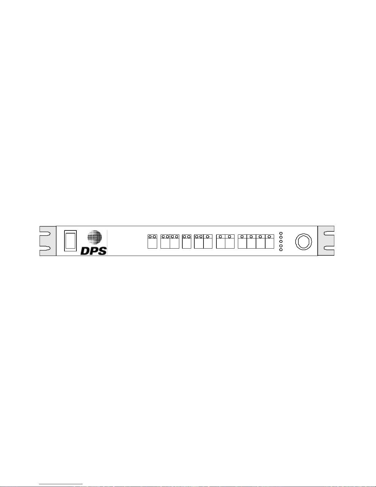
This section describes the front panel controls and indicators for the ES-2200S dual channel expansion system. The ES2200S is designed to operate any two DPS PC cards, including the DPS MicroSYNC, Personal V-Scope, and Personal
Routing Switcher.
The SELECT button is used to address the individual cards installed in the UNIT 1 and UNIT 2 positions. After
selecting a desired unit, the front panel indicators will display the selected card parameters. The momentary push
button switches on the ES-2200S front panel are used to select the various operating modes. Pressing the appropriate
button (e.g., Video) and then rotating the shaft encoder knob performs changes to a mode setting (e.g., Video Level).
The bar graph display, located to the left of the shaft encoder, provides a relative measure of the selected setting.
The labels in red located directly above the ES-2200 front panel buttons represent V-Scope functions. The labels in
black located above the V-Scope labels represent the MicroSYNC functions. The labels in blue located at the bottom of
the front panel represent special MicroSYNC functions. The actual operation of the controls depends on the
combination of cards installed in the ES-2200S chassis. For example, if a MicroSYNC was installed in UNIT 1 and a
V-Scope in UNIT 2, the upper labels in black would refer to UNIT 1 (MicroSYNC) functions and the red labels below
them would refer to UNIT 2 (V-Scope) functions.
Certain front panel controls can perform additional functions when they are held for more than one second. These
controls are designated by italic legends printed below the respective controls. All proc amp LEDs flash when one of
the Proc Amp shift functions is initiated.
24
Page 26
SELECT TIMING FREEZE FUNCTION PROC AMP
Shaft Encoder
UNIT UNIT H-POS C F FRM/FLD TAKE BYPASS PROCESS VIDEO BLACK CHROMA HUE
1 2 FLAT LOW 1H 2H PK/VAR FREEZE NRM SUPER WAVFRM VECTOR OVERLAY SPLIT
REMOTE CONFIGURE STROBE STORE RECALL PREVIOUS UNITY
VRT BLKG MONO GEN MD BURST BLK OUT SYNC MD CLAMP IN LOCK BLK CLP HOT SW
5 MAX
4 +
3 UNITY
2 -
1 MIN
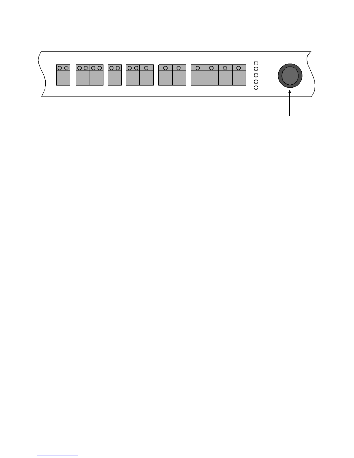
Figure 3-2: ES-2200S Controls
Unit Select
The UNIT select button is used to address the selected installed card. Whenever UNIT 1 is selected, all of the front
panel controls and indicators display the current parameters of the card installed in the UNIT 1 slot. When UNIT 2 is
selected the front panel controls and indicators display the current parameters of the card that is installed in the UNIT 2
slot. This button is also used to select remote/local operation.
UNIT 1
When this button is selected, the ES-2200S recalls and displays the current status of the card that is connected in the
UNIT 1 slot. A flashing UNIT 1 LED indicates that the installed card is not responding to the ES-2200S commands. If
this happens, make sure that the baud rate of both the front panel and the installed card are the same and that the serial
interface cable is connected. Note that this LED will not flash if the installed unit is a V-Scope or a Personal Routing
Switcher card.
UNIT 2
When this button is selected, the ES-2200S recalls and displays the current status of the card that is connected in the
UNIT 2 slot. A flashing UNIT 2 LED indicates that the installed card is not responding to the ES-2200S commands. If
this happens, make sure that the Baud rate of both the front panel and the installed card are the same and that the serial
interface cable is connected. Note that this LED will not flash if the installed unit is a V-Scope or a Personal Routing
Switcher card.
REMOTE
The remote function causes the ES-2200S to go into REMOTE mode. The installed Personal series cards and the
MicroSYNC can now accept commands from a remote source such as a computer or a remote control module. The
commands are accepted via the rear panel's DB-9 female connector, and are processed by the front panel then passed on
to the selected unit. Holding in the SELECT button for approximately one second activates this function. When this
function is active, the front panel UNIT 1 and UNIT 2 LEDs both light up. To select local mode simply press the UNIT
1/UNIT 2 button once.
25
Page 27

MicroSYNC Controls
The MicroSYNC controls are shown in bold black text on the front panel. The section below explains the effect each
control has on the installed MicroSYNC card.
Proc Amp Controls
The proc amp controls are applicable to MicroSYNC cards. The proc Amp controls are VIDEO LEVEL, BLACK
LEVEL, CHROMA LEVEL, and HUE LEVEL.
VIDEO
The VIDEO CONTROL button selects video level control for the shaft encoder. Changing the video level effects the
overall amplitude of the processed video signal, resulting in a change in the displayed picture contrast.
BLACK LEVEL
The BLACK LEVEL button selects black level control for the shaft encoder. Changing the black level effects the DC
level of the processed video signal, resulting in a change in the displayed picture brightness.
CHROMA LEVEL
The CHROMA LEVEL button selects chroma level control for the shaft encoder. The chroma level control changes the
color saturation of the processed video signal.
HUE
The HUE button selects hue control for the shaft encoder. The hue control changes the phase of the processed color
subcarrier, which effects the tint of the displayed picture.
Freeze Controls
TAKE and FRM/FLD are primary functions. STROBE is a shift function marked in italics under FRM/FLD.
TAKE
The TAKE button is used to toggle between FREEZE and LIVE modes. Note that when the unit is in the FREEZE
FIELD mode, and the FREEZE function is activated, the shaft encoder may be used to select one of the five
MicroSYNC fields captured when the FREEZE function was actuated.
FRM/FLD
This button is used to select between FRAME (FRM) and FIELD (FLD) FREEZE modes. The FRAME mode is
normally used for static scenes (i.e. no motion) because it provides better vertical resolution. The FIELD mode is used
to freeze scenes that contain motion. The shaft encoder can be used to select fields one through five. Also for the
MicroSYNC card, the freeze frame range is frame 1, frame 2 or 4-field freeze.
STROBE
The STROBE function is engaged by pressing and holding the freeze FRM/FLD button until the FRM LED begins to
flash. The STROBE mode is then entered when the FREEZE TAKE button is selected. When the unit is in strobe
mode, the shaft encoder may be used to select the desired strobe rate.
26
Page 28

Memory
These functions are shift functions below the Proc Amp controls.
The ES-2200S stores all current settings, such as Proc-amp levels and system timing, in its own non-volatile memory.
The memory is automatically updated once every three seconds. These settings are automatically recalled and
transferred to the resident MicroSYNC card on power up, so that system timing and Proc-amp levels are not lost.
System timing information is stored separately for each resident card. Proc-amp levels are stored with respect to each
MicroSYNC. Memory functions all appear as shift functions on the Proc Amp buttons.
STORE
The MEMORY STORE function causes the current proc amp settings to be saved in non-volatile memory in the ES2200S. These settings may later be recalled using the recall function. Holding in the Video button for approximately
one second activates this function. When this function occurs, the front panel proc amp LEDs will flash for one second.
RECALL
The MEMORY RECALL function is used to recall settings previously stored using the store function. Holding in the
BLACK button for approximately one second activates this function. When this function is occurs, the front panel proc
amp LEDs will flash for one second.
PREVIOUS
The MEMORY PREVIOUS function is used to return the proc amp settings to those present before a memory recall or
unity function. Holding in the CHROMA button for approximately one second activates this function. When this
function occurs, the front panel proc amp LEDs will flash for one second.
MEMORY UNITY
The MEMORY UNITY function returns all proc amp, and color balance settings to the factory preset values. Holding
in the HUE button for approximately one second activates this function. When this function occurs, the front panel proc
amp LEDs will flash for one second.
Function
PROCESS and BYPASS are primary functions.
PROCESS
When this button is selected, the MicroSYNC is in its normal operating mode.
BYPASS
When this button is pressed until the LED begins to flash, the MicroSYNC will route its video input directly to its
video output connector. While the MicroSYNC is in bypass mode, all front panel functions are disabled except for the
unit select button. Also the BYPASS LED and the CONFIGURE red LED will continuously flash.
Both PROCESS and BYPASS LEDs are distinguished when the MicroSYNC is configured for force black out.
27
Page 29

Timing
The SYSTEM TIMING controls (or GENLOCK controls) are used to modify the timing of the video outputs from the
installed MicroSYNC cards, so that correct system timing is maintained when the unit is used in conjunction with other
video processing equipment. When a reference video signal is connected to the selected (installed) MicroSYNC
reference video input, the outputs from that card will nominally be co-timed with this signal. Using the GENLOCK
controls, the installed card output video may be shifted with respect to the reference video input.
H-POS
This button enables the horizontal position of the video signal to be adjusted +/- 1 us by using the shaft encoder. The
MicroSYNC horizontal position may be adjusted only when the MicroSYNC is configured for Line Lock mode (See
the MicroSYNC user's manual).
C – F (GENLOCK TIMING)
This button enables the horizontal genlock timing to be changed via the shaft encoder. When the Coarse C genlock
timing LED is lit, the shaft encoder moves the output video signal in steps of 270 nsec, or 360 degrees. A flashing C
LED indicates that the selected unit is not genlocked.
The F (fine) button enables the fine genlock timing to be changed via the shaft encoder. The fine genlock timing moves
the output video in steps of 0.55 nsec or 0.70 degrees. A flashing subcarrier F LED indicates that the selected unit is not
genlocked.
To disable accidental genlock timing adjustments to the input reference signal, see CONFIGURATION OPTIONS later
in this chapter. If genlock adjust is disabled, no timing adjustments can be made until it is re-enabled.
WHITE CLIP (VS-2410 Only)
This feature must be enabled from the CONFIGURATION menu before any adjustment is possible. The following
page describes how to enable the WHITE CLIP feature from the CONFIGURATION menu.
Press and hold the GENLOCK TIMING button until both LEDs begin to flash. Use the shaft encoder to adjust the
WHITE CLIP level. The usable range is +/- 20 IRE where each detent, while moving the shaft encoder, represents a
change of 1 IRE.
BLACK CLIP (VS-2410 Only)
This feature must be enabled from the CONFIGURATION menu before any adjustment is possible. The following
page describes how to enable the BLACK CLIP feature from the CONFIGURATION menu.
Press and hold the H-POS button until both LEDs begin to flash. Use the shaft encoder to adjust the BLACK CLIP
level. The usable range is +/- 20 IRE where each detent, while moving the shaft encoder, represents a change of one
IRE.
28
Page 30

MicroSYNC CONFIGURE Select
The MicroSYNC card (VS-2400) can be configured with a number of CONFIGURATION functions. To change a
CONFIGURATION function, perform the following steps:
1. Choose the ES-2200 channel containing the MicroSYNC card using the UNIT 1/ UNIT 2 SELECT button.
2. Place the MicroSYNC card into CONFIGURATION mode by pressing the CONFIGURE button for one second so
that the CONFIGURE LEDs are both flashing. (Red and Green LEDs)
3. There are ten set-up options. Select the setup option by pressing the appropriate button. Setup functions are labeled
in blue, located below the push buttons.
4. Choose a mode for the selected configuration function by turning the rotary shaft encoder knob. Modes are
indicated by the number (1-5) legends located to the left of the LED level display. The default value for each setup
option is 1. The following table details the various configuration function choices.
Remember, after changing one or more of these MicroSYNC configure modes, the unit will remain in
CONFIGURATION mode until you press the CONFIGURE button to return the synchronizer to normal operation.
Once the CONFIGURE LEDs are extinguished, the buttons return to their primary functions, denoted by the black
legend located above each button.
NOTE: In normal mode, If the red LED on the CONFIGURE button flashes, this indicates that there is no valid NTSC
signal feeding the synchronizer or that the MicroSYNC is in BYPASS mode.
29
Page 31

MicroSYNC Configuration Functions
Button Function/ Mode
VRT BLKG Vertical Blanking Width
1. Narrow
2. Wide
MONO Monochrome Mode
1. Normal
2. Forced Monochrome
GEN MD Genlock Adjust
1. Auto
2. External Reference
3. Internal Reference
4. Ext. Ref. and Genlock Adjust Disable
5. Auto and Genlock adjust Disable
BURST Output Burst Mode
1. Auto
2. On
3. Off
VID ADV Video Advance
(VS-2410 only) 1. Normal
2. Advance Video 1 line
3. Advance Video 2 lines
SYNC MD Synchronizer Mode
1. 4-Field
2. Frame (2-Fields)
3. Hot Frame
CLAMP Clamp Speed Select
1. Normal
2. Fast
IN LOCK Input Lock Mode
1. Auto
2. Burst
3. Line
CLIP MD Clip Mode Select
1. Clipping Off (Default
* 2. Black & White Clip On
3. Black Clip On, White Off
* 4. Black Clip Off, White On
HOT SW Hot Switch Mode
1. Off
2. Freeze Frame
3. Black
* VS-2410 Only
Note: Mode 1 is the default factory setting for all functions.
30
Page 32

V-Scope Controls
V-Scope commands appear in red directly above the front panel buttons. They are valid when the selected unit
is a V-Scope, as determined by the DIP Switch settings outlined in the installation section of this manual.
WAVFRM
Places the V-Scope in FULL SCREEN WAVEFORM DISPLAY mode.
VECTOR
Places the V-Scope in FULL SCREEN VECTOR DISPLAY SCOPE mode.
OVRLAY
Places the V-Scope in FULL SCREEN WAVEFORM + VECTOR SCOPE OVERLAY mode. This produces a display
with both full screen waveform monitor and full screen vector scope simultaneously displayed.
SPLIT
Places the V-Scope in WAVEFORM AND VECTOR SCOPE SCREEN mode. This produces a display in which the
top half of the screen shows live video and the bottom half consists of quarter-sized waveform monitor and vector
scope displays placed side by side.
NRM
Places the V-Scope in the NORMAL DISPLAY mode. The V-Scope display is updated every two frames.
SUPER
Enables the superimpose output from the V-Scope, which contains the synthesized waveform/vector display as
determined by the other selections (i.e., waveform, vector mode).
PK/VAR
Selects between PEAK-HOLD and VARIABLE DISPLAY modes. When PEAK-HOLD is selected, old data is not
erased. A cumulative display showing all peak video excursions results. When VARIABLE is selected, rotate the shaft
encoder to select a display rate and change the display update rate. Increasing the rate produces a more fully colored
display.
FREEZE
Freezes the V-Scope trace, providing an instantaneous snap shot of the current waveform/vectors display.
1H/ 2H
Selects between 1-H (single video line) and 2-H (dual video line) display modes. 1-H mode provides the best display
resolution. Use the 2-H mode to view the horizontal blanking interval of the video signal.
LOW
Sets the V-Scope in the low pass frequency response mode. This is normally used when setting white or black levels
while viewing the V-Scope waveform monitor display.
FLAT
Sets the V-Scope in the flat frequency response mode.
Note: The NORMAL display command is sent to the V-Scope upon selection of any of the above modes except
FREEZE, PEAK HOLD, and VARIABLE modes.
31
Page 33
RS-2800 Personal Routing Switcher
PROC AMP
IN-1 IN-2 IN-3 IN-4
CLAMP IN LOCK BLK CLP HOT SW
Routing Switcher commands are not on the ES-2200T front panel. A stick-on label is provided with each switcher card.
This label should be applied to the front panel underneath the proc amp controls.
The ES-2200S can be configured to control one or two switcher cards. The Routing Switcher card has a four by one
(4x1) switching matrix accessible through the four input BNC connectors at the rear of the card. The Routing switcher
card also has an eight by one (8x1) switching matrix accessible through the Edge connector. When the Personal
Routing Switcher card is used in the ES-2200S, the 8x1 matrix can’t be accessed and therefore can’t be used. The 4x1
matrix can be controlled by the front panel as indicated by the label.
Place Sticker Here
STORE RECALL PREVIOUS UNITY
IN-1
When selected, the Personal Routing Switcher routes the video source on input #1 to the output BNC.
IN-2
When selected, the Personal Routing Switcher routes the video source on input #2 to the output BNC.
IN-3
When selected, the Personal Routing Switcher routes the video source on input #3 to the output BNC.
IN-4
When selected, the Personal Routing Switcher routes the video source on input #4 to the output BNC.
32
Page 34
Chapter 4:
GENLOCK TIMING
REMOTE INPUT (RJ-14)
Video Connections
This section describes the inputs and outputs of the various cards that can be installed in the ES-2000 Expansion
system.
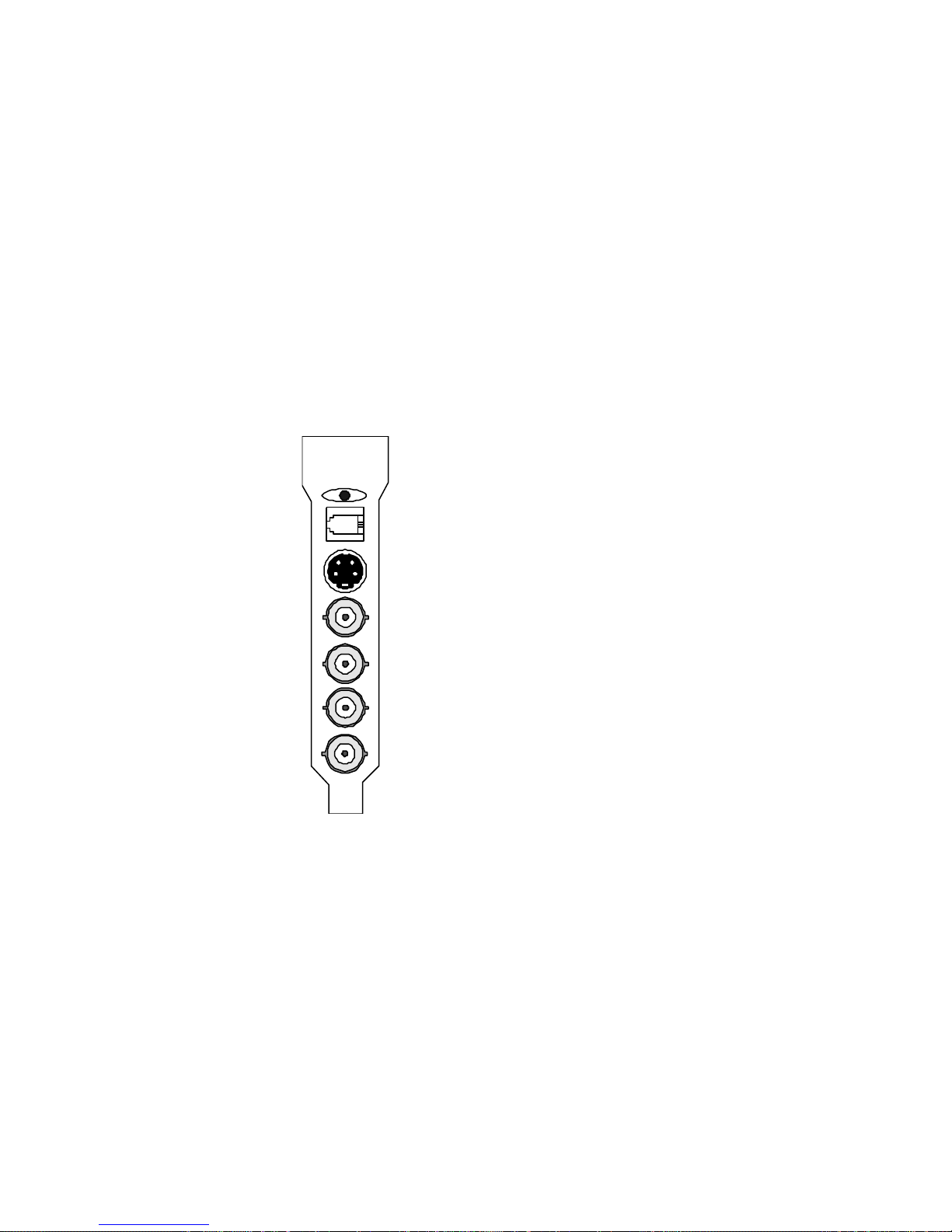
Personal TBC III Connectors
S-VIDEO INPUT
NTSC VIDEO INPUT
NTSC VIDEO OUTPUT
MULTI I/O OUTPUT
GENLOCK INPUT
FIGURE 4-1: Personal TBC III I/O Connectors
SERIAL DATA INPUT (RJ-14)
This connector is not used when the TBC III card is used in the ES-2200 Expansion System.
S-VIDEO INPUT
This 4-pin connector is used to input S-Video (SVHS or Hi8) to the TBC card. It is normally connected to the S-Video
output of a playback VCR using a standard 4-pin to 4-pin S-Video cable. Some JVC industrial S-VHS players use a 7pin connector for their S-Video output. To interface with such machines, a 7-pin to 4-pin adapter cable is required.
NTSC VIDEO INPUT
This BNC connector feeds composite NTSC video to the TBC card. It can be connected to the video output of a
playback VCR or any composite NTSC source such as a TV tuner, laser disk player, camera, etc.
33
Page 35
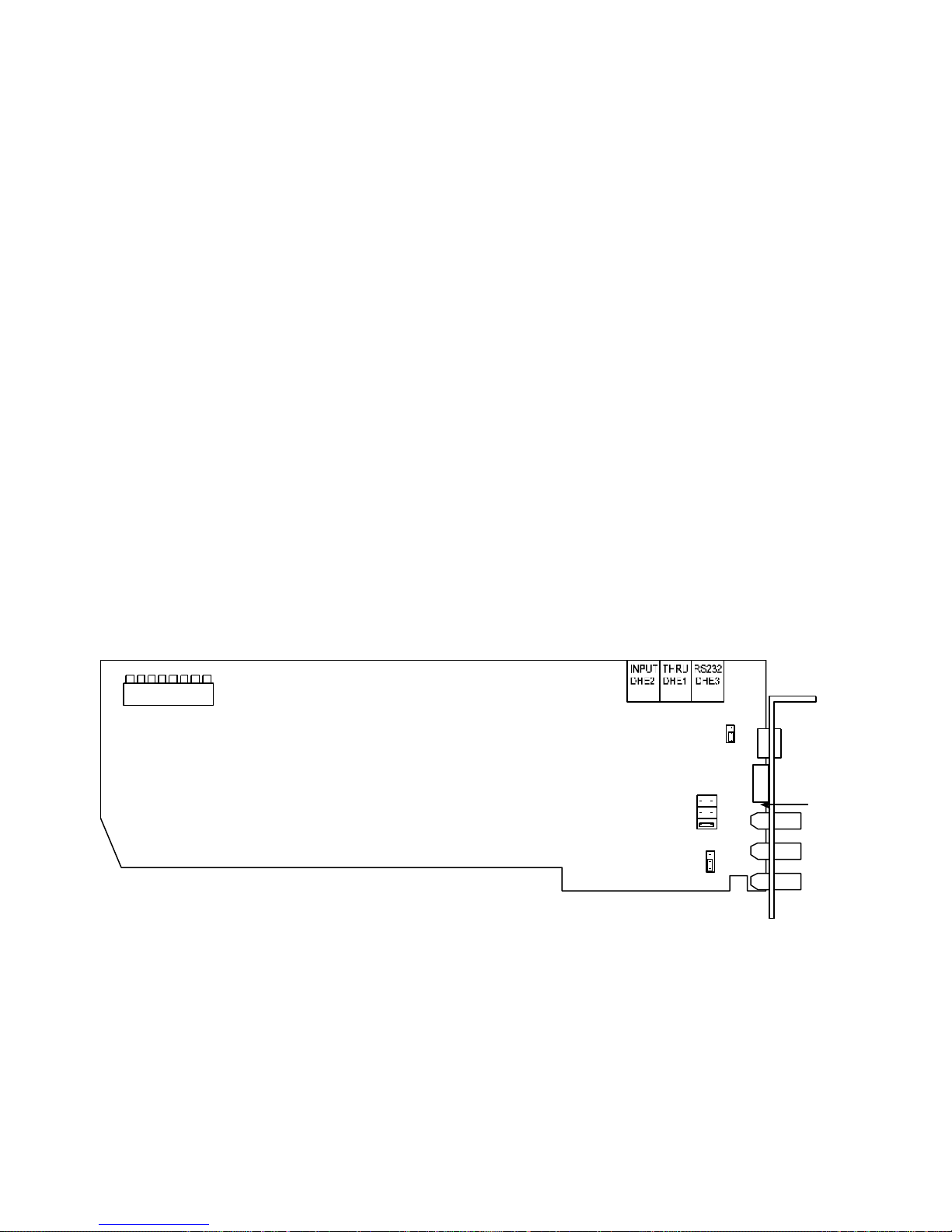
NTSC VIDEO OUTPUT
DHE 4
Multi-I/O
Serial Data
Transmit Control
TERM
OPEN
Video Out
Genlock Termination
This BNC type connector outputs the time-base corrected version of the video input signal.
GENLOCK OK LED
This LED will light when a valid genlock video signal is connected to the TBC card genlock video input.
MULTI INPUT/OUTPUT (I/O) CONNECTOR
TBC card jumper CHE1 controls the use of this connector. Normally, this connector is used as a loop through for the
genlock video signal. This allows the same genlock signal to be looped to a number of destinations. It may also be used
for an advanced sync output by moving CHE1 to the SYNC position. You can connect the advanced sync output from
this connector to the EXT SYNC input on the playback VCR (if the VCR has this feature). For more information on the
advanced sync see Appendix A of the TBC III manual. The final mode for the multi I/O connector provides a second
time base corrected video output that is identical to the main video output. It is obtained by moving CHE1 to the
VIDEO position.
GENLOCK VIDEO INPUT
The TBC card uses the genlock video input to establish the timing for its video output signal. The signal connected to
this input must always be stable, such as the output from a black burst or color bar generator. DO NOT attempt to use a
non-timebase corrected VCR for your genlock reference. When a valid signal is connected to this input, the video
output of the TBC card will be co-timed (genlocked) to this signal and the rear panel genlock OK will light. When no
external reference is supplied to the genlock input, the TBC card operates using its internal sync generator.
GENLOCK TIMING ADJUSTMENT
The rear panel genlock timing adjustment is only used when the TBC card is installed in an application where it will
not be under serial control. When installing TBC cards into the ES-2200 chassis, the genlock timing is controlled by the
front panel or with the appropriate software via the rear panel DB-9 RS-232 interface.
8 7 6 5 4 3 2 1
BSW1
DIP Switches
Figure 4-2: TBC III Card
INTERNAL SERIAL DATA
CONNECTORS
Adv Sync
Genlock Loop
CHE2
CHE1
TX
MT
Function
34
Page 36
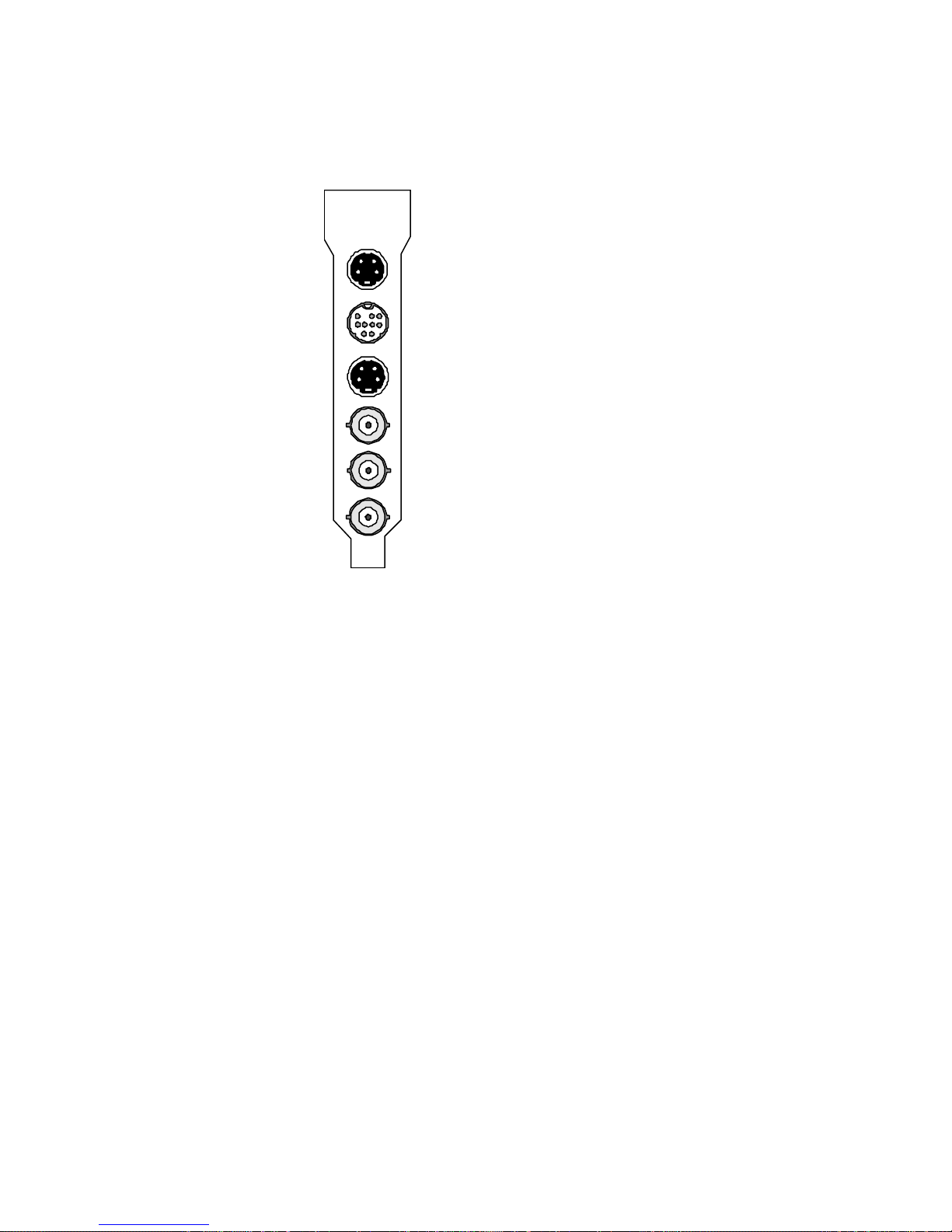
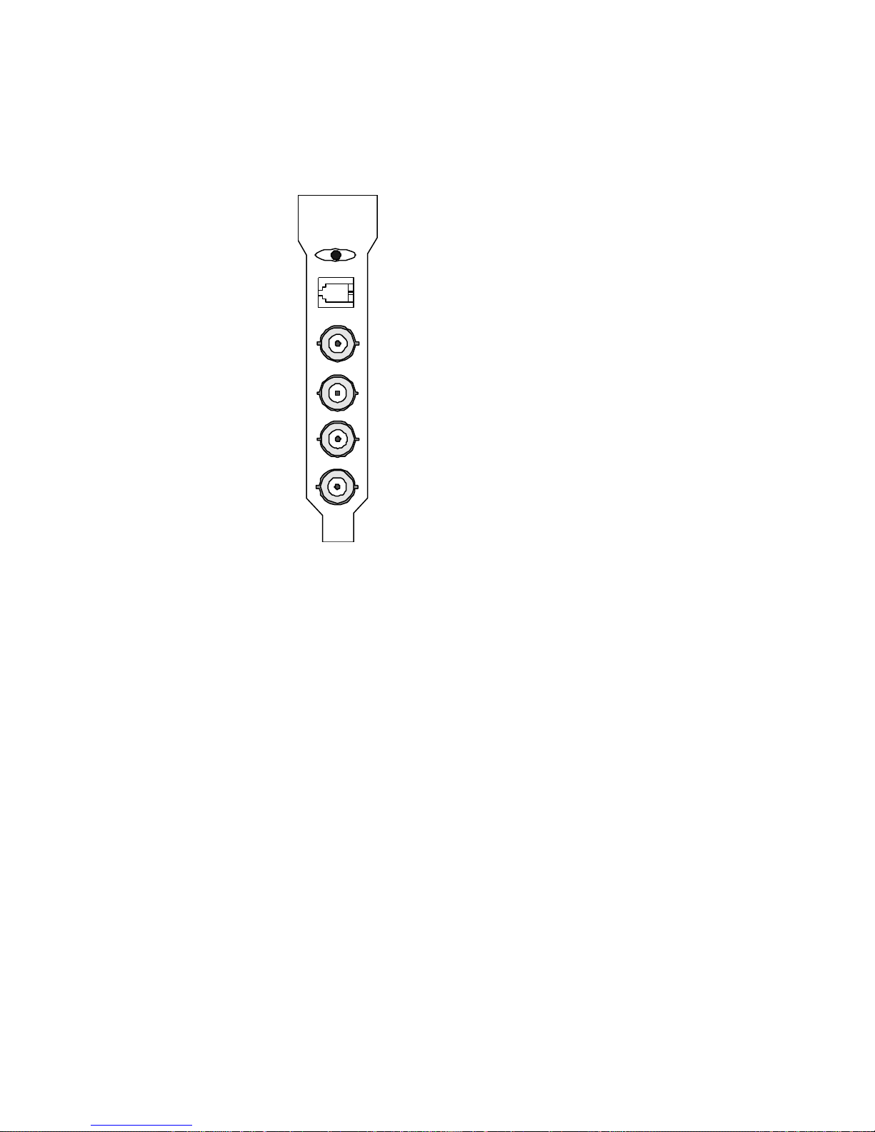
Personal TBC IV Connectors
S-VIDEO IN
MULTI DIN-9
S-VIDEO OUT
NTSC VIDEO IN
NTSC VIDEO OUT
GENLOCK IN
FIGURE 4-3: Personal TBC IV I/O Connectors
S-VIDEO INPUT
Use this 4-pin connector to input S-Video (S-VHS or Hi8) to the TBC card. It is normally connected to the
S-Video output of a playback VCR using a standard 4-pin to 4-pin S-Video cable. Some JVC industrial type
S-VHS players use a 7-pin connector for their S-Video output. To interface with such machines, a 7-pin to
4-pin adapter cable is required.
MULTI FUNCTION I/O (DIN-9)
This jack connects the Personal TBC IV card to an available computer RS-232 serial port using the supplied DIN-9-M
to DB-25 cable. This feature is not used when the TBC IV is installed in an ES-2200T Expansion System.
The multi-function DIN-9 connector may be used as an advanced sync output by connecting the DPS 774-519 multifunction cable (not included), and using the advanced sync BNC. The advanced sync signal can be fed to the EXT
SYNC input of a suitably equipped playback VCR. For more information on advanced sync, refer to Appendix C in
your TBC IV manual.
S-VIDEO OUTPUT
This 4-pin connector provides a time base corrected S-Video (S-VHS or Hi8) version of the video input signal.
NTSC VIDEO INPUT
This BNC connector is used to feed composite NTSC video to the TBC card. It is normally connected to the video
output of a playback VCR. It can also be connected to any composite NTSC source such as a TV tuner, laser disc
player, camera, etc.
35
Page 37
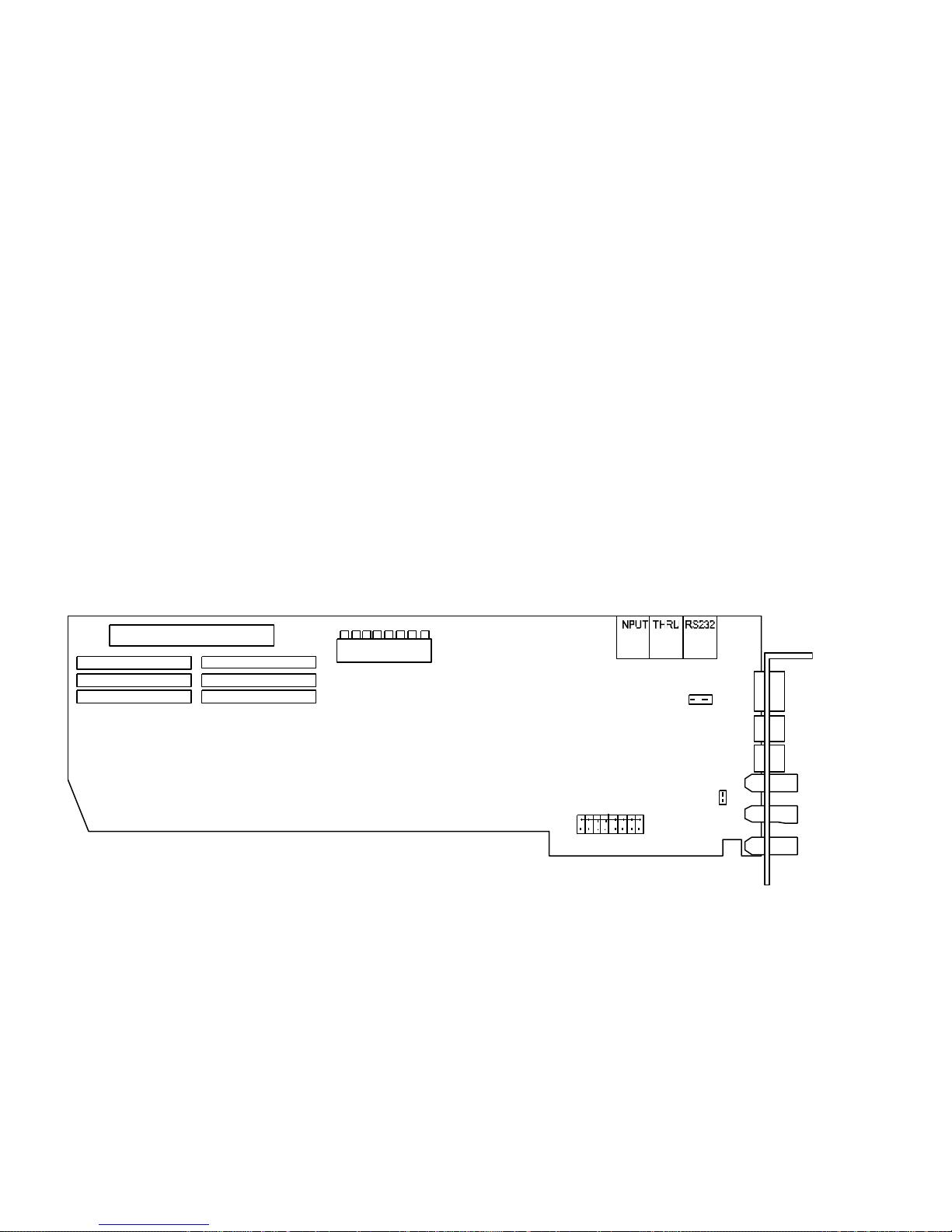
NTSC VIDEO OUTPUT
CHE6
8 7 6 5 4 3 2 1
AHE5
This BNC connector provides a timebase corrected version of the video input signal.
GENLOCK OK LED
This LED will light when a valid genlock video signal is connected to the TBC genlock video input.
GENLOCK VIDEO INPUT
The TBC card uses genlock video input to establish timing for its video output signal. The signal connected to this
input must always be stable, such as the output from a black burst or color bar generator. DO NOT attempt to use a
non-time base corrected VCR for your genlock reference. With a valid signal connected to this input, the video output
of the TBC card will be co-timed (genlocked) to this signal. The rear panel genlock OK LED will light. When no
external reference is supplied to the genlock input, the TBC IV uses its internal sync generator. To loop the genlock
reference to another device, use the provided BNC Y cable DPS part #774-517.
Figure 4-4: TBC IV Card
8 7 6 5 4 3 2 1
BSW1
DIP Switches
DHE2 DHE1 DHE3
INTERNAL SERIAL DATA
CONNECTORS
-----------P1-B12
-----------P1-B14
-----------P1-B16
-----------P1-B18
-----------P1-B20
-----------P1-B22
-----------P1-B24
-----------P1-B26
CHE4
36
Page 38
DPS 8-Bit MicroSYNC Connectors
GENLOCK TIMING
NTSC VIDEO INPUT
NTSC VIDEO OUTPUT
GENLOCK LOOP THROUGH
REMOTE IN
GENLOCK VIDEO INPUT
FIGURE 4-5: DPS MicroSYNC I/0 Connectors
SERIAL DATA INPUT (RJ-14)
This connector is not used when the MicroSYNC is installed in an ES-2200 Expansion System.
NTSC VIDEO INPUT
NTSC video can be connected to the MicroSYNC card in two ways: through the BNC connector as shown in Figure 45 or from the card edge connector as shown in Figure 4-6. The two position jumper CHE2 is used to select the video
input to the MicroSYNC card. Jumper CHE2 is labeled BNC and BUS and is factory set to BNC. The BUS video input
can only be used when both a MicroSYNC and a DPS RS-2800 Personal Video Routing Switcher are installed in an
ES-2000 expansion chassis.
The input to the MicroSYNC card should be 1 V p-p NTSC video signal. It is terminated with 75O at the card. This
signal may be direct color or monochrome. The MicroSYNC cannot be used directly with non-timebase corrected
heterodyne VCRs such as U-Matic and VHS recorders, since it is not a TBC. Typical input sources include satellite,
network, mobile and other remote video feeds. This MicroSYNCs video input is automatically looped to the output
BNC whenever power is off or BYPASS mode is selected.
NTSC VIDEO OUTPUT
This connector, as shown in Figure2-5, supplies a nominal 1 V p-p, 75O composite NTSC output. The video output
contains a synchronized version of the video input signal except when the MicroSYNC is in Bypass or Black mode.
37
Page 39
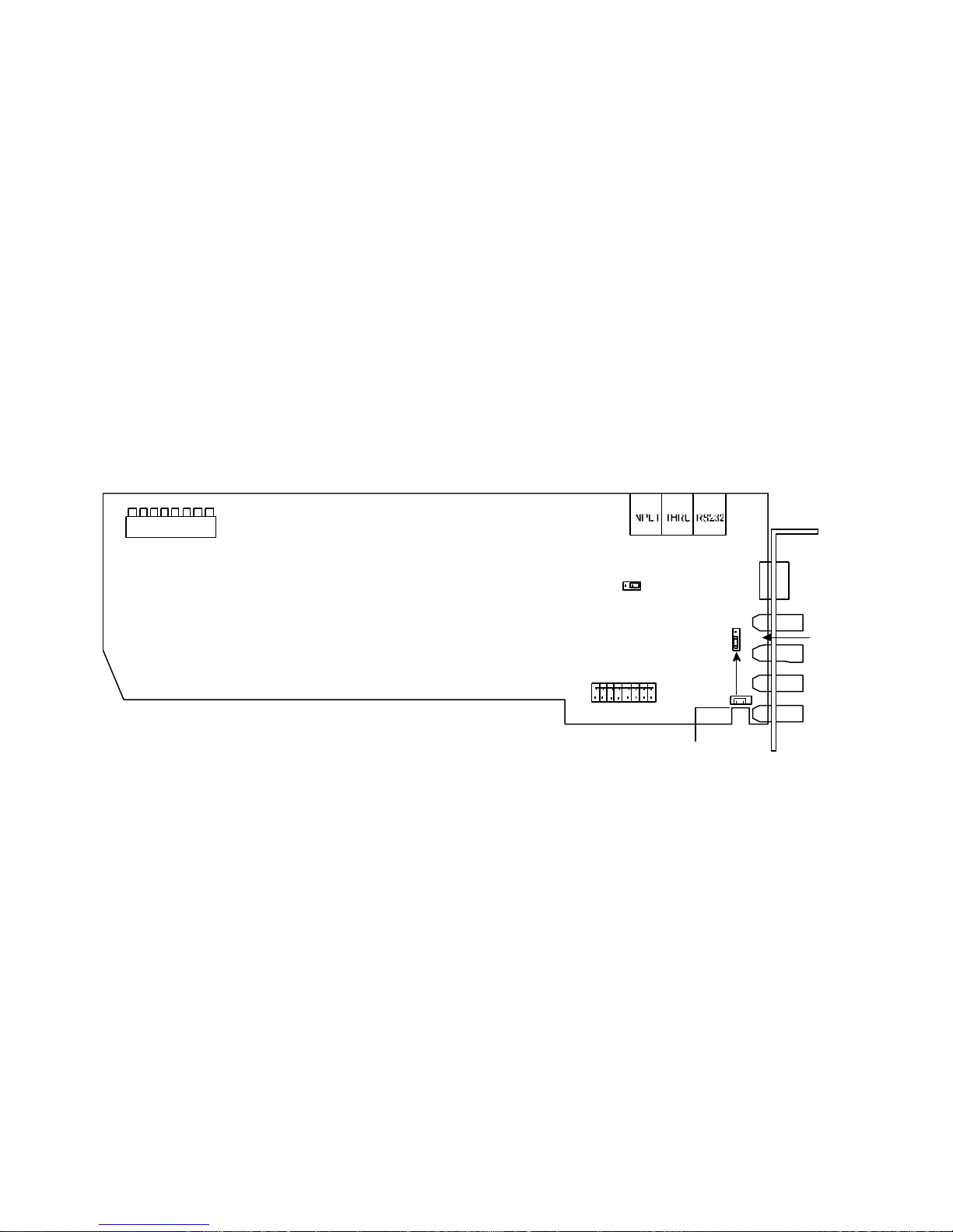
GENLOCK OK LED
DHE 4
8 7 6 5 4 3 2 1
MicroSYNC
BNC Input
P1-B5
MicroSYNC
-----------P1-B12
-----------P1-B14
-----------P1-B16
-----------P1-B18
-----------P1-B20
-----------P1-B22
-----------P1-B24
-----------P1-B26
Do not install jumper CHE3 unless is being fed by a single
RS-2800 Routing Switcher.
This LED will light when a valid genlock video signal is connected to the MicroSYNC genlock video input.
REFERENCE VIDEO INPUT
These two BNC connectors provide a loop-through (bridging) connection for the genlock reference input. Composite
color black or another stable composite video signal such as color bars should be used as a genlock reference. The
signal loop should always be terminated in 75O. If the MicroSYNC card represents the end of the reference loop, a
precision 75O BNC terminating plug should be installed on the unused jack.
When stand-alone operation is desired, the MicroSYNCs genlock external/internal option should be set to internal. This
option can be set via software or from the front panel of an ES-2200 series expansion chassis.
GENLOCK TIMING ADJUSTMENT
The rear panel genlock timing adjustment can only be used when the MicroSYNC remote control capability is disabled
(DIP Switch 8 DOWN). Do not adjust this switch if you are operating the MicroSYNC by the RC-2000 control panel.
8 7 6 5 4 3 2 1
BSW1
DIP Switches
INTERNAL SERIAL DATA
CONNECTORS
MUTE
TRANSMIT
Serial Data
Transmit Control
DHE5
MicroSYNC Video
BUS Output
Note:
Figure 4-6: DPS 8-Bit MicroSYNC Card
CHE2
BUS Input
CHE3
BNC
BUS
38
Page 40
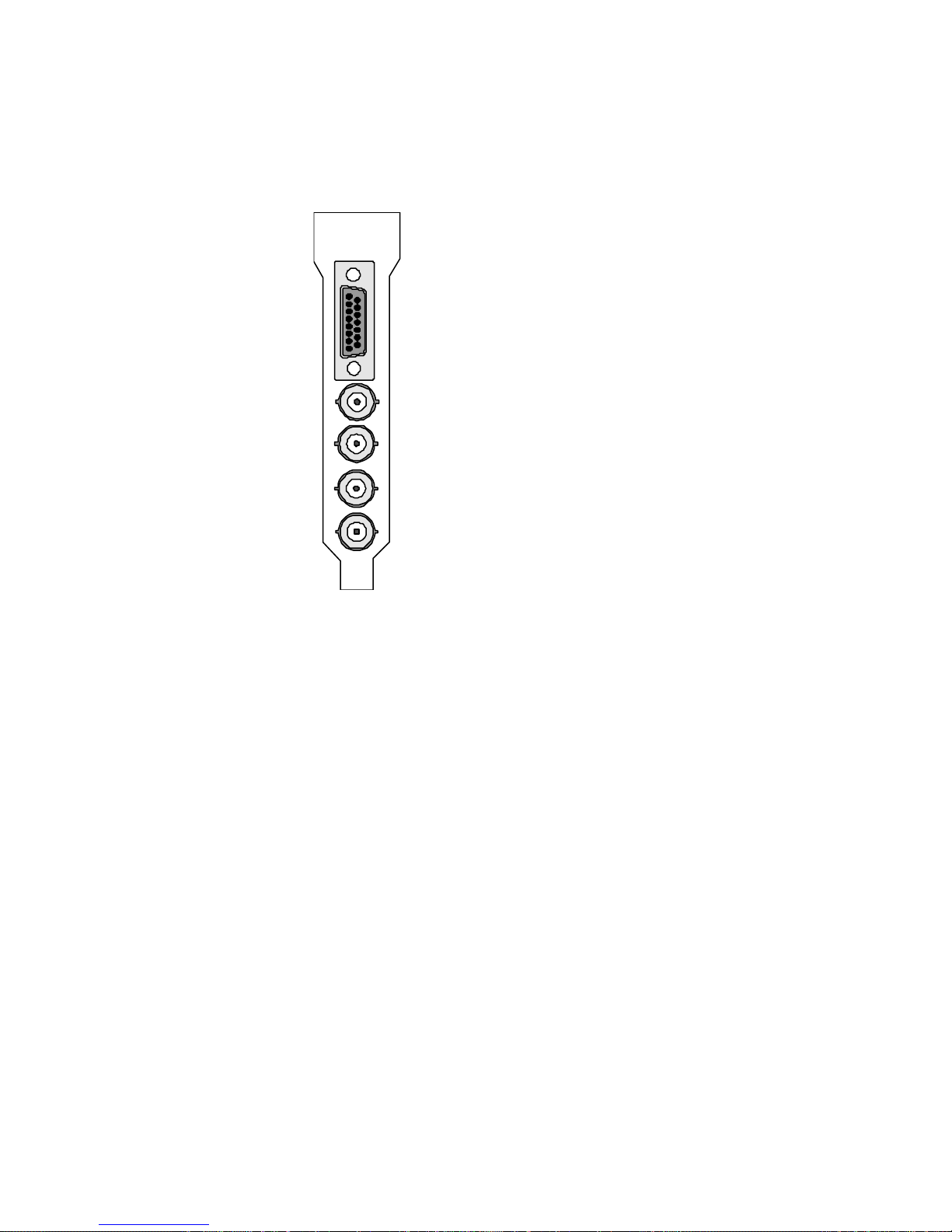
DPS MicroSYNC-X Connectors
MULTI I/O (DB-9)
NTSC VIDEO INPUT
NTSC VIDEO OUTPUT
GENLOCK LOOP THROUGH
GENLOCK VIDEO INPUT
Figure 4-7: DPS MicroSYNC-X I/O Connectors
MULTI I/O (DB-9)
This jack is used to provide RS-232 control, video monitor output, audio delay TTL pulse, RC-2000 remote control
power (+12VDC) and GND freeze input. This jack is generally used when the MicroSYNC-X card is installed in a PC
and not used when the card is installed in an ES-2000 Expansion System.
NTSC VIDEO INPUT
NTSC video can be connected to the MicroSYNC card in two ways: through the BNC connector as shown in Figure 23 or from the card edge connector as shown in Figure 4-8. The two-position jumper CHE2 is used to select the video
input to the MicroSYNC card. Jumper CHE2 is labeled BNC and BUS and is factory set to BNC. The BUS video
input can only be used when both a MicroSYNC and a DPS RS-2800 Personal Video Routing Switcher are installed in
an ES-2000 expansion chassis.
The input to the MicroSYNC card should be 1 V p-p NTSC video signal. It is terminated with 75? at the card. This
signal may be direct color or monochrome. The MicroSYNC cannot be used directly with non-timebase corrected
heterodyne VCRs such as U-Matic and VHS recorders, since it is not a TBC. Typical input sources include satellite,
network, mobile and other remote video feeds. This MicroSYNC’s video input is automatically looped to the output
BNC whenever power is OFF or BYPASS mode is selected.
39
Page 41
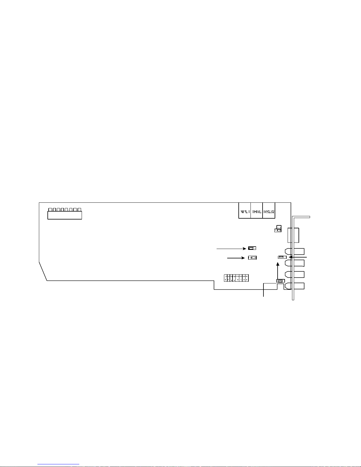
NTSC BNC VIDEO OUTPUT
GND 4
DHE 4
TRANSMIT
Transmit Control)
Video Monitor
8 7 6 5 4 3 2 1
MicroSYNC
BNC Input
P1-B5
MicroSYNC
-----------P1-B12
-----------P1-B14
-----------P1-B16
-----------P1-B18
-----------P1-B20
-----------P1-B22
-----------P1-B24
-----------P1-B26
DHE6 should remain in the off position unless MicroSYNC-X
is to be externally controlled using an RC-2000
This connector supplies a nominal 1 V p-p, 75? composite NTSC output. The video output contains a synchronized
version of the video input signal except when the MicroSYNC is in BYPASS or BLACK mode.
NTSC BUS VIDEO OUTPUT
A second video output is routed to the eight-position jumper field DHE5. This enables the user to route the
MicroSYNC video output to any one of eight different card edge connector pins. The BUS output can be used to feed
the 8x1 input matrix of one or more DPS RS-2800 routing switcher cards when they are installed together in a DPS ES2000 expansion chassis.
GENLOCK OK LED
This LED will light when a valid genlock video signal is connected to the MicroSYNC genlock video input.
REFERENCE VIDEO INPUT
These two BNC connectors provide a loop-through (bridging) connection for the genlock reference input. Composite
color black or another stable composite video signal such as color bars should be used as a genlock reference. The
signal loop should always be terminated in 75 ?. If the MicroSYNC card represents the end of the reference loop, a
precision 75 ? BNC terminating plug should be installed on the unused jack.
8 7 6 5 4 3 2 1
BSW1
DIP Switches
RC-2000 Power
(+12 VDC)
INTERNAL SERIAL DATA
CONNECTORS
(Serial Data
ON
OFF
DHE6
DHE7
DHE5
CHE2
BUS Input
CHE4
MUTE
BUS
BNC
Figure 4-8: DPS MicroSYNC-X Card
Note:
40
Page 42
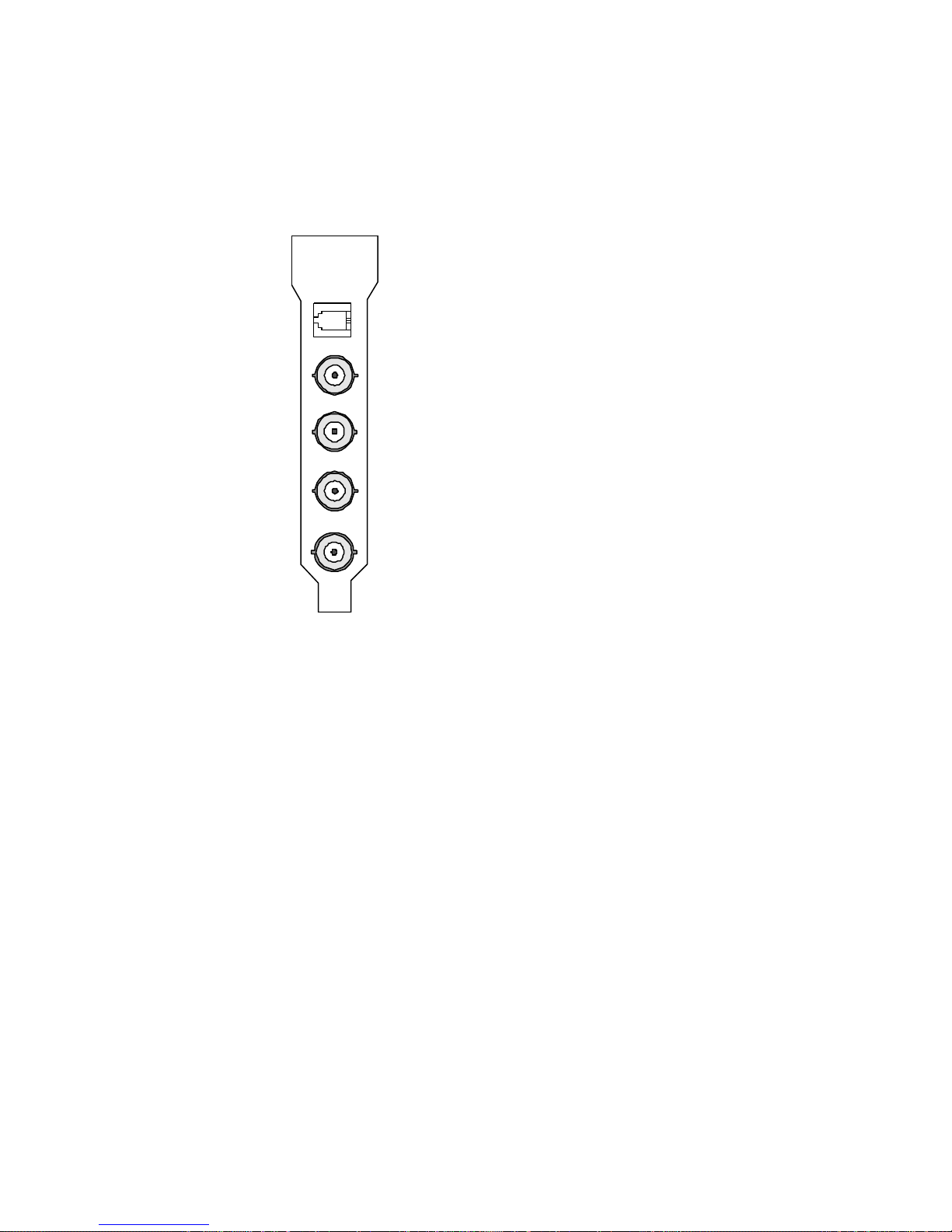
Personal V-Scope Connectors
BUFFERED VIDEO OUTPUT
REMOTE IN (RJ-14)
NTSC VIDEO INPUT
SUPERIMPOSE OUTPUT
FULL-TIME OUTPUT
Figure 4-9: Personal V-Scope I/O Connections
SERIAL DATA INPUT (RJ-14)
This connector is not used when the V-Scope card is installed in an ES-2200 Expansion System.
NTSC VIDEO INPUT
This BNC connector is used to feed composite NTSC video to the V-Scope card. It is normally connected to the
program output of your video switcher. The video signal input on this connector will appear at the buffered video
output and in the background on both the superimpose and full-time outputs.
VIDEO OK LED
This LED lights when a valid NTSC signal is applied to the video input connector.
41
Page 43
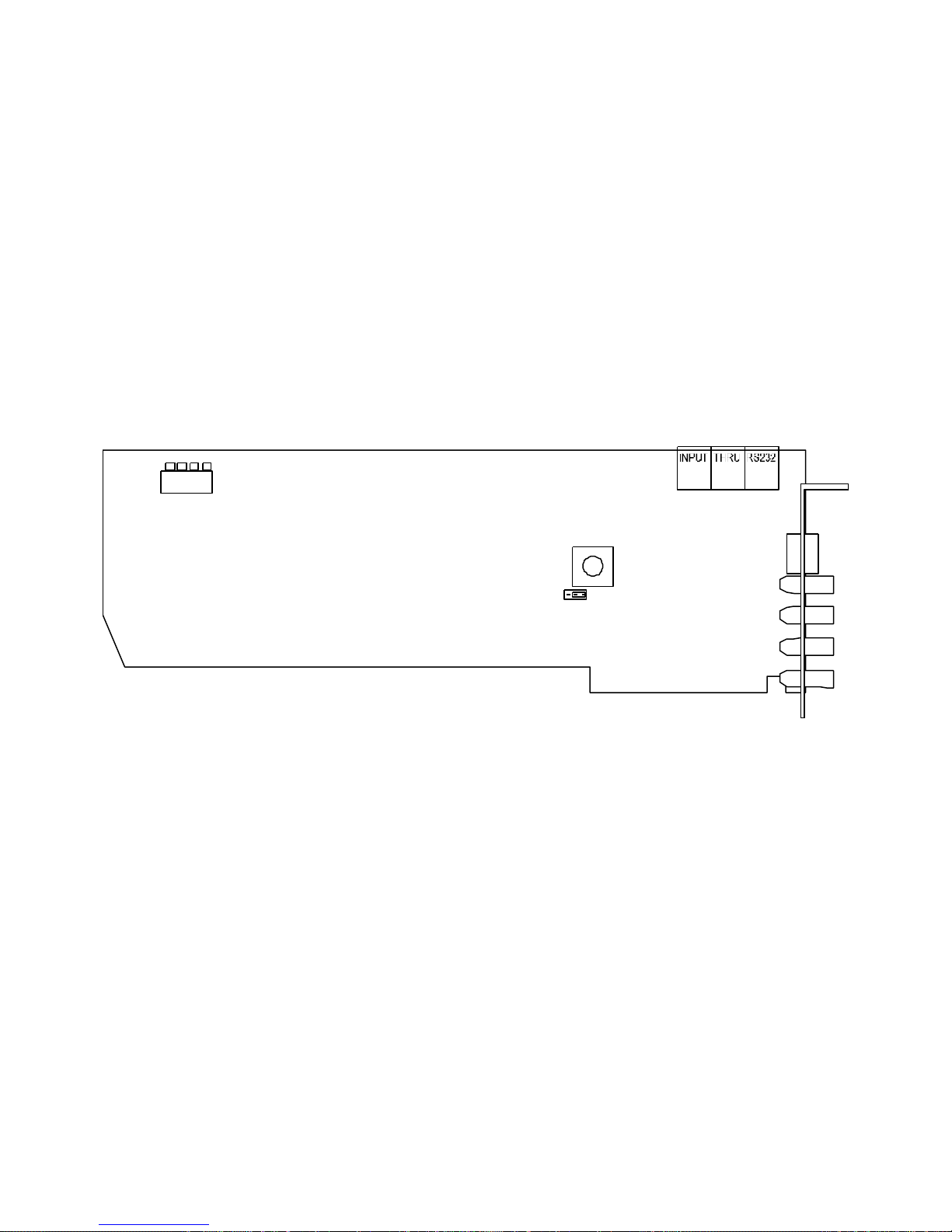
BUFFERED VIDEO OUTPUT
DHE2 DHE1 DHE3
B&W COLOR
This BNC type connector provides a buffered video output signal, which is a copy of the video signal applied to the
input connector. It is normally connected to your record VCR.
SUPERIMPOSE OUTPUT
The ES-2000 front panel V-Scope control selection determines this BNC type connector output. When the
SUPERIMPOSE mode is selected, this output will contain the synthesized waveform/vector display superimposed on
the video input signal. When the SUPERIMPOSE mode is not selected, this output will be a copy of the video input
signal.
FULL TIME OUTPUT
This BNC type connector output contains the synthesized waveform/vector display superimposed on the input video
signal at all times. This output is normally connected to a video monitor (if one is available) which is dedicated to
displaying the V-Scope waveform/vector information.
4 3 2 1
DIP Switches
INTERNAL SERIAL DATA
CONNECTORS
CHE1
W/F Output
Figure 4-10: DPS Personal V-Scope Card
42
Page 44
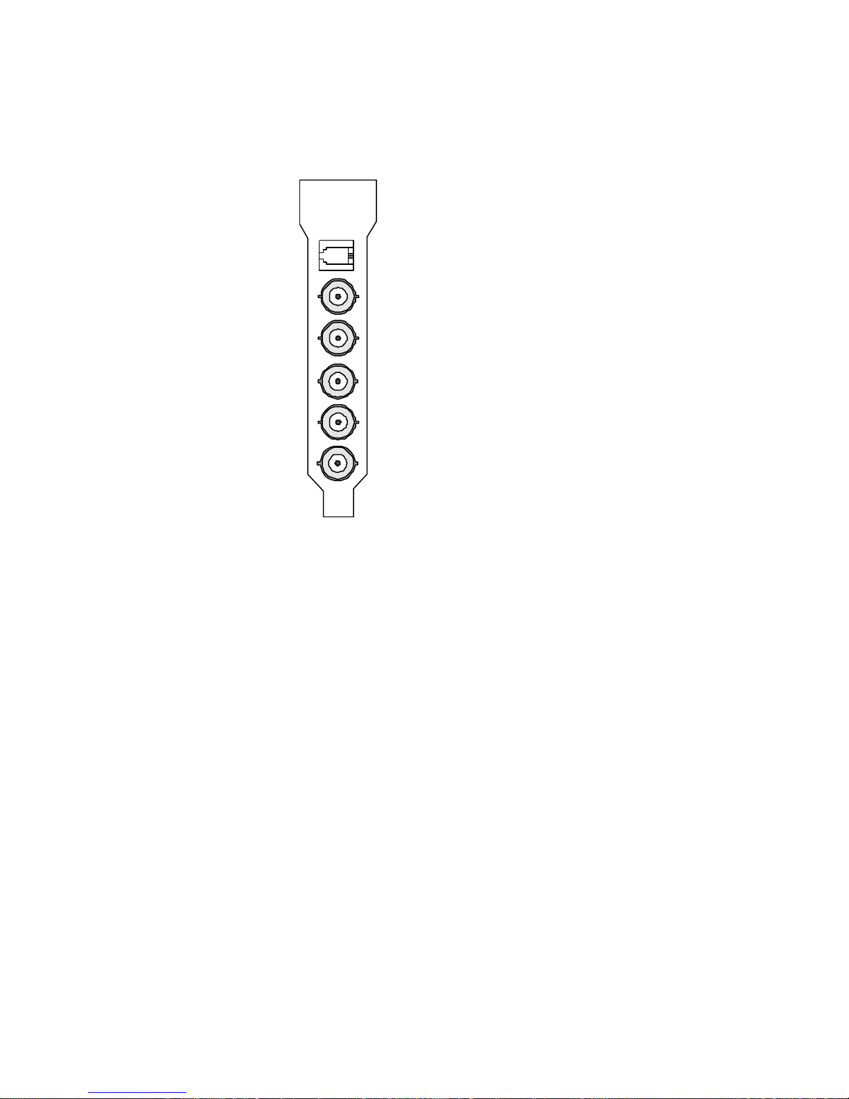
Personal Video Routing Switcher
REMOTE INPUT (RJ-14)
4x1 VIDEO INPUT #1
4x1 VIDEO INPUT #2
4x1 VIDEO INPUT #3
4x1 VIDEO INPUT #4
BNC VIDEO OUTPUT
Connectors
FIGURE 4-11: Personal Video Routing Switcher I/O
Connections
INPUTS
4X1 SWITCHING MATRIX INPUTS
The inputs to the 4x1 switching matrix come from the four BNC inputs (Figure 4-11) and are AC coupled into
the board. A jumper header is provided at each input to allow for clamping of the input video signal (DC restorer). If
clamping is desired for any of the BNC video inputs, install a jumper in the desired header location (AHE5, AHE6,
AHE7, and AHE8). (Figure 4-12)
8X1 SWITCHING MATRIX INPUTS
The inputs to the 8x1 switching matrix come from the card edge connector (Figure 4-12). They cannot be used
when the RS-2800 is installed in an ES-2200 Expansion System.
43
Page 45
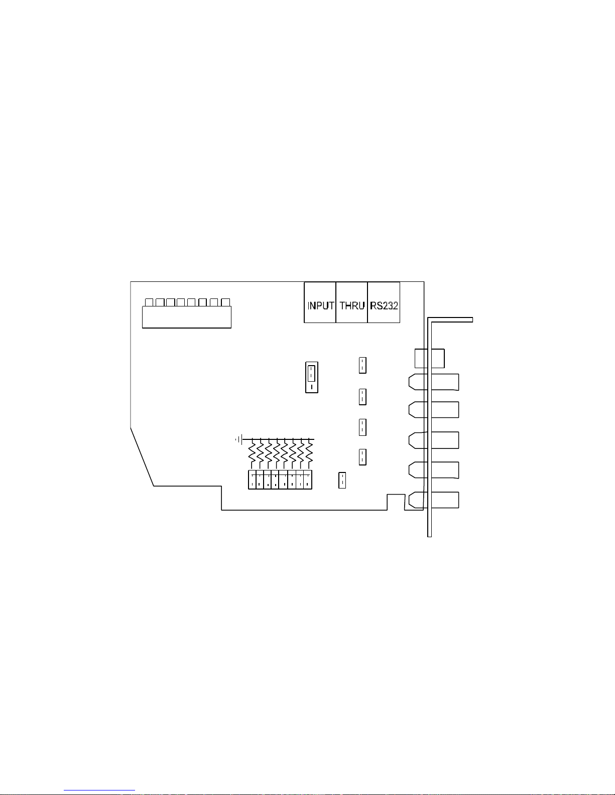
Outputs
AHE5
AHE6
AHE7
AHE8
IN 3
IN 2
IN 4
IN 1
110R
110R
110R
110R
110R
110R
110R
Vertical Blanking Interval
BNC OUTPUT
The BNC output is shown in Figure 4-11. This BNC connector contains the selected RS-2800 4x1 or 8x1
video output.
BNC CONTROL
The outputs of the 4x1 and 8x1 switching matrices are connected to the input of the BNC multiplexer (MUX).
This MUX routes the selected 4x1 or the 8x1 matrix outputs to the RS-2800s BNC video output connector under
control of the microprocessor. Unless the RS-2800 is installed in a DPS ES-2000 expansion chassis and configured to
utilize the 8x1 matrix, the BNC control MUX should be set to the 4x1 switching matrix position.
8 7 6 5 4 3 2 1
BSW1
INTERNAL SERIAL DATA
DIP Switches
AHE10
SOURCE: 4x1
SOURCE: 8x1
8 7 6 5 4 3 2 1
---------P1-B20
---------P1-B22
---------P1-B24
---------P1-B26
---------P1-B18
AHE9
Switching Jumper
110R
Video BUS Output
---------P1-B12
---------P1-B14
---------P1-B16
CONNECTORS
4x1
UP
DOWN
4x1
4x1
4x1
AHE4 PI-B5
Figure 4-12: DPS Personal Routing Switcher Card
44
Page 46
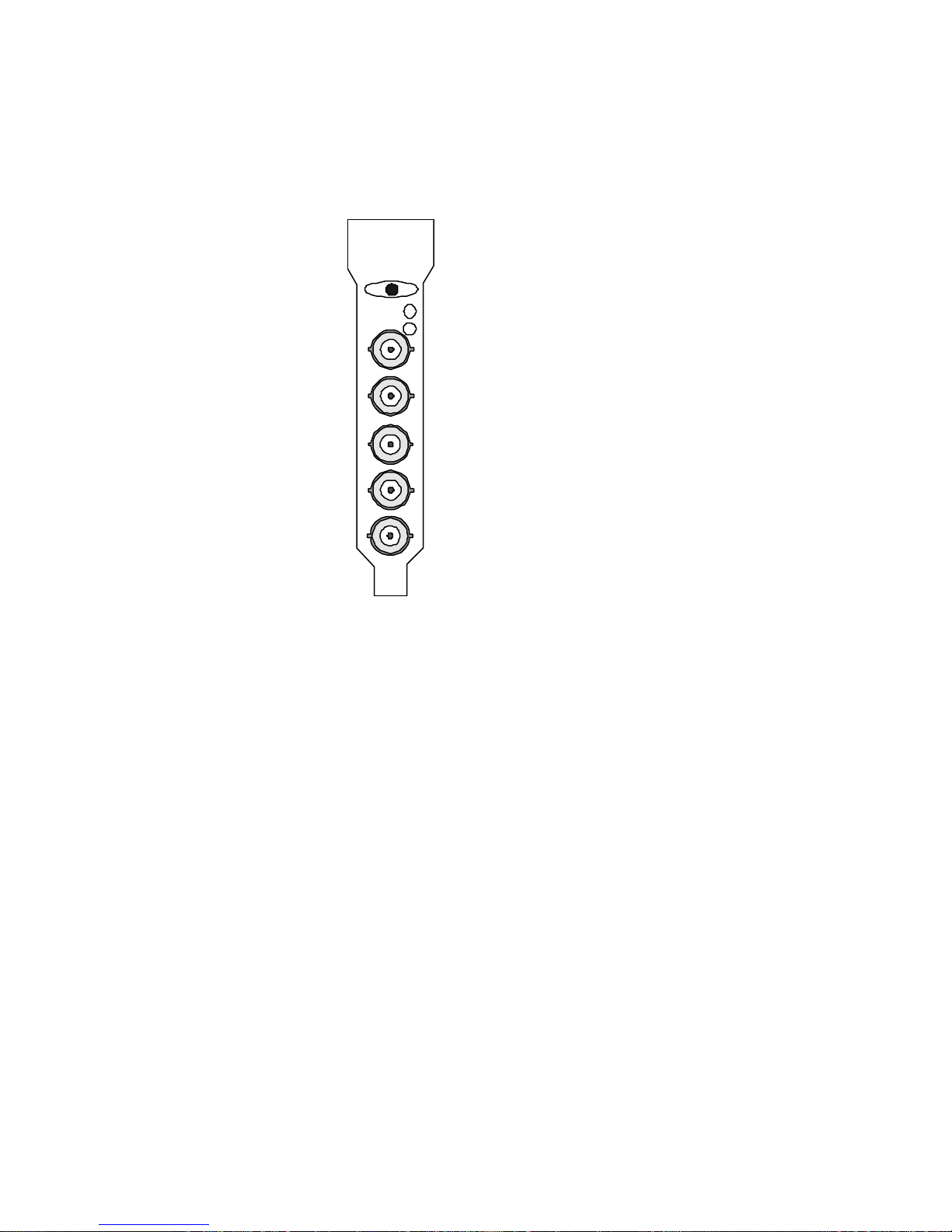
Personal VDA Connectors
TERMINATION SWITCH LEFT 75-OHM/RIGHT BRIDGE
ARV1 GAIN POT
ARV2 GAIN POT
VIDEO INPUT
VIDEO OUTPUT 1
VIDEO OUTPUT 2
VIDEO OUTPUT 3
VIDEO OUTPUT 4
FIGURE 4-13: Personal VDA I/O Connectors
VIDEO INPUT
This connector is used to input composite NTSC video to the VDA card. This signal is AC coupled and fed to the VDA
video amplifiers.
VIDEO OUTPUT 1
This is output 1 of the VDA card, its output impedance is 75O. The output gain can be adjusted +/- 2dB using
potentiometer ARV1.
VIDEO OUTPUT 2
This is output 2 of the VDA card. Its output impedance is 75O. The output gain can be adjusted +/- 2dB using
potentiometer ARV1.
VIDEO OUTPUT 3
This is output 3 of the VDA card. Its output impedance is 75O. The output gain can be adjusted +/- 22dB using
potentiometer ARV2.
VIDEO OUTPUT 4
This is output 4 of the VDA card. Its output impedance is 75O. The output gain can be adjusted +/- 2dB using
potentiometer ARV2.
45
Page 47
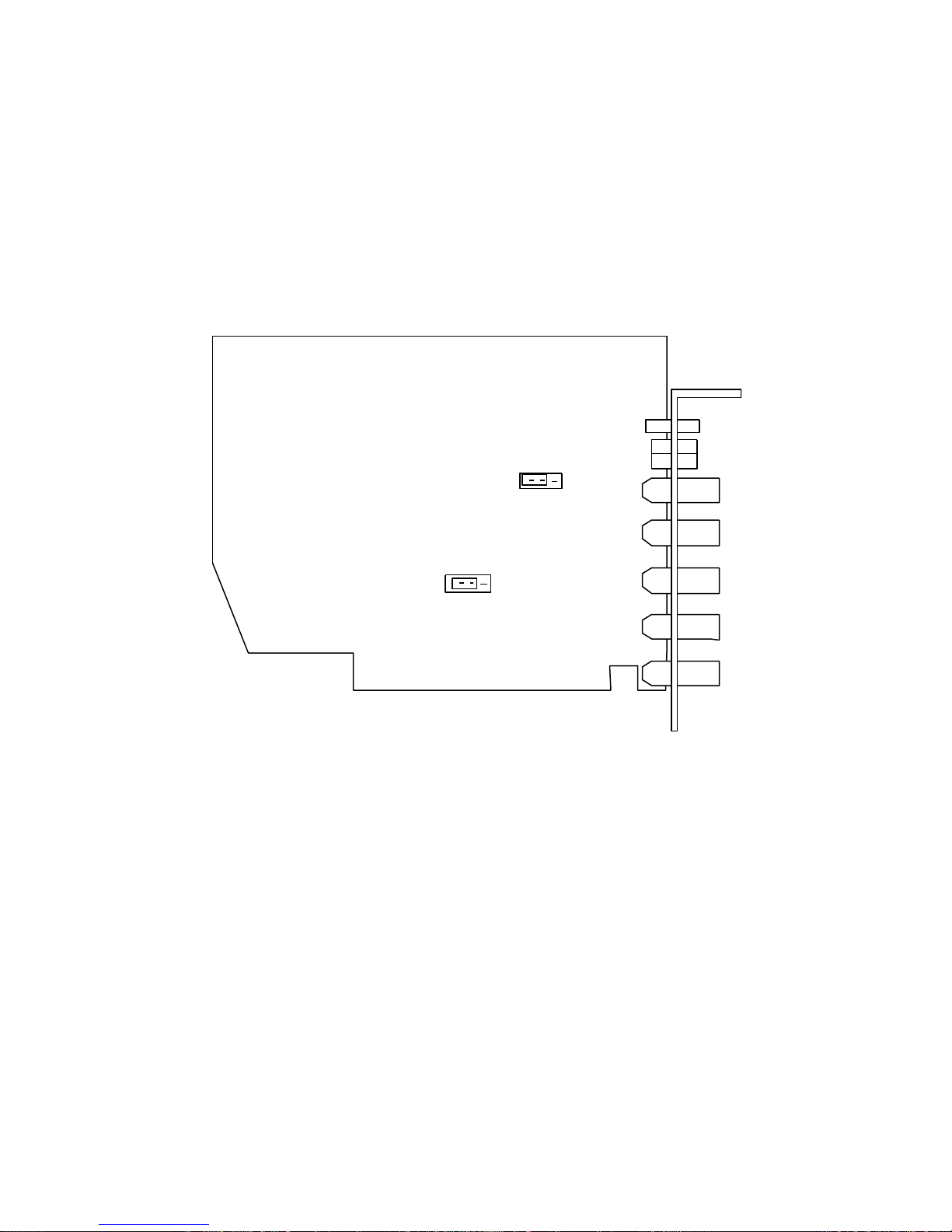
TERMINATION SWITCH
AHE2
DC Offset
Set this switch to the left (away from the PC board) to terminate the input of the VDA into 75O. Set the switch to the
right for a high impedance (bridging) input. A BNC T connector can be used to provide a loop-through connection.
OFF
-12v
ON
AHE1
-5v
Negative Volts
Select
Figure 4-14: VDA Card
46
Page 48

Chapter 5:
Remote Control
Note: This section applies to the ES-2200T and the ES-2200S
There are three possible methods of remote controlling the cards installed inside an ES-2200 (or multiple ES-2200
units). The first method is to use DPS developed computer software and to remote control the ES-2200 from a Personal
computer or an Amiga computer. The second is to use DPS's desktop remote control, the RC-2000. The third method
would require that the user develop custom remote software based on the protocol provided in Appendix B.
DPS Computer Software
Computer Software is included with every purchase of individual TBC, V-Scope, Switcher, and MicroSYNC cards.
This computer software is available in two versions, one for AMIGA computers and the other for IBM compatible PCs.
Traditionally this software is used to remotely control the TBC IV, TBC III, V-Scope, and MicroSYNC cards that are
installed inside an IBM PC or an AMIGA computer. This software can also be used to remote control the cards
installed inside the ES-2200. ES-2200 owners can obtain this software at no charge by contacting DPS.
The user must set the ES-2200 remote address to same address of the card installed in the UNIT 1 slot. If you wish to
control more than one ES-2200, then the cable that connects the computers serial port to the first ES-2200 must also
connect all other ES-2200s to the computer's transmit and ground lines. In other words, the computers transmit and
ground line must be daisy chained to all of the ES-2200s in a system. Figure 5-3 shows multiple ES-2200s connected
together. The use of flat ribbon cable and insulation displacement DB-9 connectors can facilitate a multi-unit
installation.
After installing the TBC IV, TBC III or MicroSYNC software in the computer, set the computer’s Baud rate to 9600
BPS. (In the case of a PC the remote software automatically configures the PC to 9600 Baud), then connect the
computer’s serial port to the ES-2200. The user must provide the connecting cable. The ES-2200 has a DB-9 female
connector that accepts RS-232 levels, which can be connected to the computer’s serial port directly. Figure 5-1 shows
the pin-out of the ES-2200 remote port. Before attempting to remote control the ES-2200, make sure that the front
panel of the ES-2200 has full control of the cards installed inside it. This will assure that the communication between
the ES-2200 and its resident cards is correct.
If you have only one ES-2200, then the factory preset is the correct address (DIP Switches 1, 2, 3, 4 and 5 UP on the
ES-2200T and 2, 3, 4, 5 and 6 UP on the ES-2200S). If you have more than one ES-2200 to be remoted, always set the
address of the ES-2200 to the same address as the card in the UNIT 1 slot. Each card inside the ES-2200 must have a
unique address (except for V-Scope cards). It is important that every ES-2200 has the same address as the card installed
in its unit 1 position.
To Place the ES-2200 in remote mode, press and hold the REMOTE button down for one second. Both UNIT 1 and
UNIT 2 LEDs will light up. The ES-2200 is now ready to be remoted. Always remember to set the baud rate of the
computer, ES-2200, and the cards inside the ES-2200 to the same baud rate.
Run the software on the computer. The manuals provided with the cards will assist you in this. The DPS software
screen should appear on the computer screen (IBM or AMIGA). The software will now allow the user to send
commands to the cards that are installed inside the ES-2200. The ES-2200 will echo all of the received commands to
47
Page 49

the resident TBC, MicroSYNC and V-Scope cards. The AMIGA can control a maximum number of eight TBC and
MicroSYNC cards. The IBM PC can control a maxiumum of thirty-two TBC and MicroSYNC cards. Any V-SCOPE
command sent by the computer will affect all of the V-Scopes installed in all of the ES-2200s that are linked together.
There are three rules that must be followed when setting a card address inside an ES-2200:
The Address of the ES-2200 must be set to the same address as the card installed in the UNIT 1 slot. Set DIP Switches
5, 4, 3, 2 and 1on the ES-2200T front panel or DIP Switches 6, 5, 4, 3 and 2 on the
ES-2200S in same direction as DIP Switches 3, 4, 5, 6 and 7 respectively on the card installed in the UNIT 1 slot
(except V-Scopes). For example, if the card in the UNIT 1 slot had its DIP Switches set to:
3 UP
4 DOWN
5 DOWN
6 DOWN
7 DOWN
Then the switches inside the front of the ES-2200T chassis should be set to:
1 DOWN
2 DOWN
3 DOWN
4 DOWN
5 UP
Or the switches inside the front of the ES-2200S chassis should be set to:
2 DOWN
3 DOWN
4 DOWN
5 DOWN
6 UP
The address of the card installed in the UNIT 2 slot must be one address greater than that of the card installed in the
UNIT 1 slot. (Except V-Scopes)
The Baud rate of the all the cards and of the ES-2200 front panel should be the same. The Default factory setting is
9600 BPS.
Unlike the TBC IV/ MicroSYNC cards, all V-SCOPES respond to address byte 10 Hex. Therefore all V-SCOPES in a
system will respond to any V-SCOPE command regardless of the ES-2200 address. V-Scopes should be installed in the
UNIT 2 slot only. (See figures 5-3 and 5-4.)
48
Page 50

Card Addressing
When installing multiple cards in a system, you must establish a unique address for each card. The software control
program uses this address to direct commands to individual cards. The table below indicates how the switch settings
correspond to buttons on the control screen. If you have only one addressable card in the system, leave these five
switches in the UP position.
Unit number Switch 3 Switch 4 Switch 5 Switch 6 Switch 7
Unit #1 UP UP UP UP UP
Unit #2 DOWN DOWN DOWN DOWN DOWN
Unit #3 DOWN DOWN DOWN DOWN UP
Unit #4 DOWN DOWN DOWN UP DOWN
Unit #5 DOWN DOWN DOWN UP UP
Unit #6 DOWN DOWN UP DOWN DOWN
Unit #7 DOWN DOWN UP DOWN UP
Unit #8 DOWN DOWN UP UP DOWN
Unit #9 DOWN DOWN UP UP UP
Unit #10 DOWN UP DOWN DOWN DOWN
Unit #11 DOWN UP DOWN DOWN UP
Unit #12 DOWN UP DOWN UP DOWN
Unit #13 DOWN UP DOWN UP UP
Unit #14 DOWN UP UP DOWN DOWN
Unit #15 DOWN UP UP DOWN UP
Unit #16 DOWN UP UP UP DOWN
Unit #17 DOWN UP UP UP UP
Unit #18 UP DOWN DOWN DOWN DOWN
Unit #19 UP DOWN DOWN DOWN UP
Unit #20 UP DOWN DOWN UP DOWN
Unit #21 UP DOWN DOWN UP UP
Unit #22 UP DOWN UP DOWN DOWN
Unit #23 UP DOWN UP DOWN UP
Unit #24 UP DOWN UP UP DOWN
Unit #25 UP DOWN UP UP UP
Unit #26 UP UP DOWN DOWN DOWN
Unit #27 UP UP DOWN DOWN UP
Unit #28 UP UP DOWN UP DOWN
Unit #29 UP UP DOWN UP UP
Unit #30 UP UP UP DOWN DOWN
Unit #31 UP UP UP DOWN UP
Unit #32 UP UP UP UP DOWN
49
Page 51
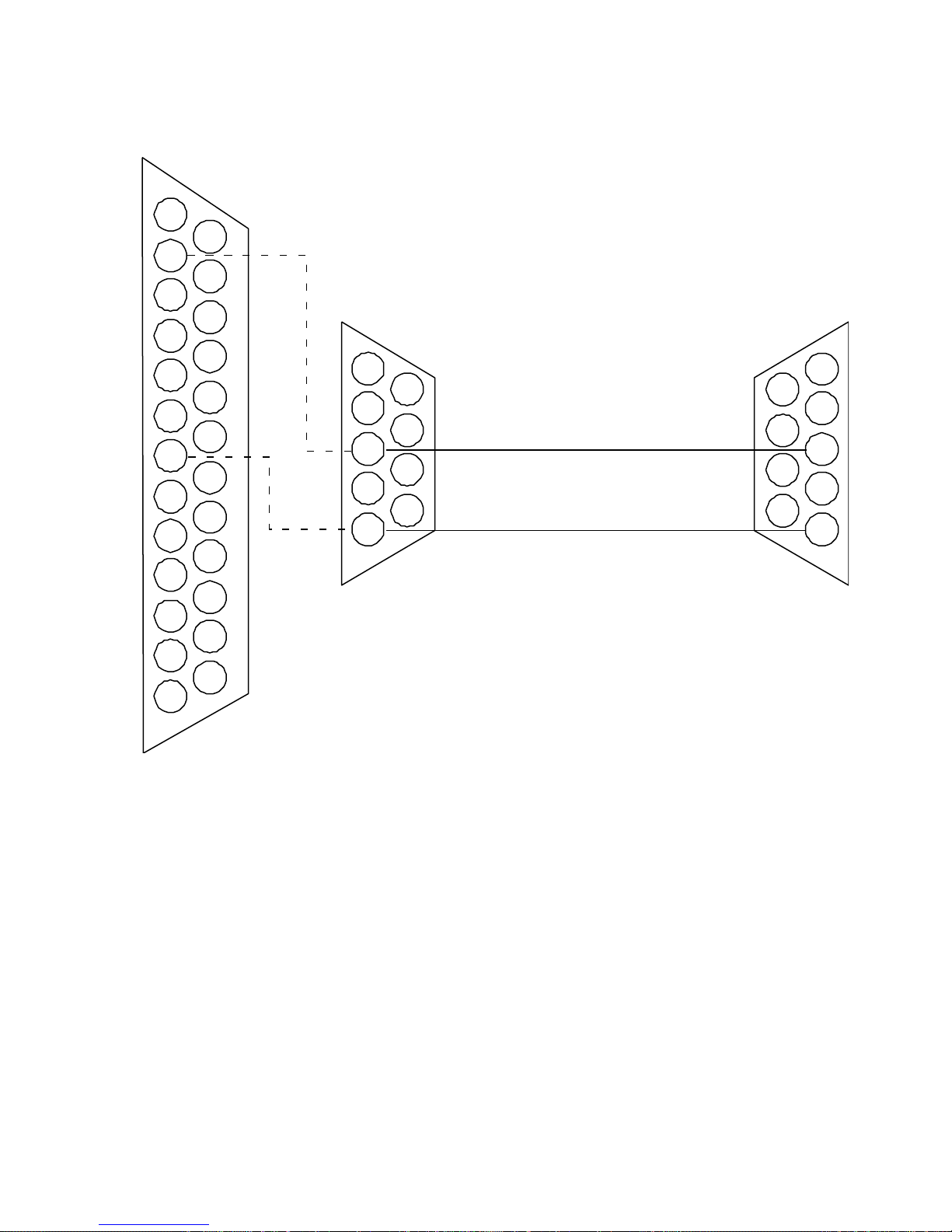
COMPATIBLE COMPUTERS’
(ALTERNATE)
DB-25F CONNECTOR
1
14
2
15
3
16
4
17
5
18
6
19
7
20
8
21
9
22
10
23
11
24
12
25
13
DB-9-F
CONNECTOR
1
6
2
7
3
8
4
9
5
CONNECT TO IBM PC
DB-9-M
CONNECTOR
1
6
2
7
3
8
4
9
5
CONNECT TO ES-2200
RS-232 REMOTE
INPUT CABLE
RS-232 PORT
Figure 5-1: Computer Serial Port to ES-2200 Cable Assembly
RC-2000 Remote Control
The DPS RC-2000 desktop remote is capable of controlling up to thirty-two DPS Personal TBC IV, TBC III, TBC II,
MicroSYNC, and RS-2800 Personal Switcher card as well as a DPS Personal V-Scope. The RC-2000 takes the place of
the host computer’s serial port and connects directly to the DB-9 connector at the ES-2200 rear panel. An external AC
adapter provides power for the RC-2000.
All video proc amp, timing functions, and setup memories can be accessed via the RC-2000’s front panel controls.
When using an RC-2000, set the ES-2200 into remote control mode and ensure that the RC-2000 and the ES-2200 are
set to the same baud rate. Please refer to the RC-2000 instruction manual for specific instructions regarding its use. The
user must provide their own remote cable to connect the RC-2000 RS-232 port to the ES-2200 RS-232 remote control
port as shown in Figure 5-4.
50
Page 52

RC-2001 Remote Control
The DPS RC-2001 desktop remote is capable of controlling up to thirty-two DPS Personal TBC IV, TBC III, TBC II,
MicroSYNC, and RS-2800 Personal Switcher card as well as a DPS Personal V-Scope. The RC-2001 takes the place of
the host computer’s serial port and connects directly to the DB-9 connector at the ES-2200 rear panel. An external AC
adapter provides power for the RC-2001.
All video proc amp, timing functions, and setup memories can be accessed via the RC-2001’s controls. When using an
RC-2001, set the ES-2200 into remote control mode and ensure that the RC-2001 and the ES-2200 are set to the same
baud rate. Please refer to the RC-2001 instruction manual for specific instructions regarding its use. The user must
provide their own remote cable to connect the RC-2001 RS-232 port to the ES-2200 RS-232 remote control port as
shown in Figure 5-4.
Each device to be controlled must have a unique hexadecimal address assigned to it. See chart page 7 for specific Unit
addresses. When a Personal Series product is connected to the RC-2001, any settings changes must be made from the
RC-2001, not locally from the unit under control. The RC-2001 must know what addresses have been assigned.
If you are using multiple RC-2001 units, refer to the RC-2001 manual for instructions on connecting them together.
System Addressing
All DPS products to be controlled using the RC-2001 must have a unique address assigned to them using the
procedures outlined for that specific device. As the ES-2200 is no longer controlling the cards once the cable from the
RC-2001 is installed, you must set an individual address for each card installed in the ES-2200 unit that is to be
controlled by the RC-2001. The RC-2001 does not recognize the ES-2200 chassis, but just the cards therein. Refer to
the instruction manuals for the cards to be controlled for information on how to address each card.
In addition, the RC-2001 must know what device is to be controlled and what address in hexadecimal it is located at.
Each card inside the ES-2200 chassis must have an individual hexadecimal address.
Hexadecimal Addresses for DPS MicroSYNC, TBC and RS-2800 cards.
40h Unit 1
00h Unit 2
01h Unit 3
02h Unit 4
03h Unit 5
04h Unit 6
05h Unit 7
06h Unit 8
Hexadecimal Addresses for DPS V-SCOPE cards.
10h Unit 1
11h Unit 2
For information on setting devices and addresses for the units to be controlled, refer to your RC-2001 operator’s
manual.
51
Page 53
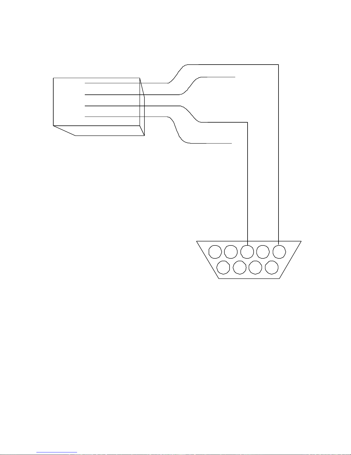
BLACK
GREEN
YELLOW
RECEIVE GROUND
INPUT PORT
TAB DOWN, 4-PIN MODULAR
TELCO HANDSET PLUG
CONNECT TO RC-2000
RS-232 REMOTE PORT
(TYPE RJ-14)
RED
1 2 3 4 5
6 7 8 9
NOTE:
RC-2000 MUST BE
POWERED BY AN EXTERNAL
9 VDC ADAPTOR
DB-9-M CONNECTOR
CONNECT TO ES-2200
RS-232 REMOTE
Figure 5-2: RC-2000 to ES-2200 Cable Assembly
52
Page 54
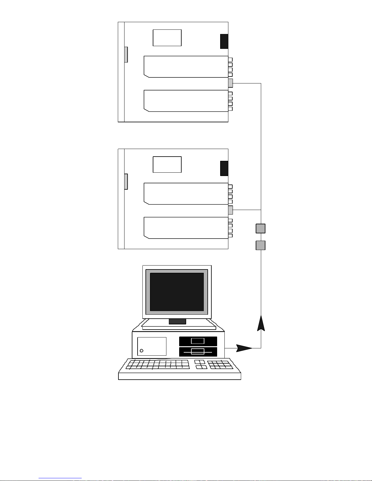
ES-2200 #1
ES-2200 #2
Ribbon Cable Daisy Chain
DB-9-F
DB-9-M
Computer Control
ES-2200S
DIP Switches
2 UP
3 UP
4 UP
5 UP
6 UP
ES-2200T
DIP Switches
1 UP
2 UP
3 UP
4 UP
5 UP
Power Supply
Unit 1
TBC Card
Unit 2
TBC Card
DIPSwitches
3 UP
4 UP
5 UP
6 UP
7 UP
DIP Switches
3 DOWN
4 DOWN
5 DOWN
6 DOWN
7 DOWN
DB-9-M
ES-2200S
DIP Switches
2 UP
3 DOWN
4 DOWN
5 DOWN
6 DOWN
ES-2200T
DIP Switches
1 UP
2 DOWN
3 DOWN
4 DOWN
5 DOWN
Power Supply
Unit 3
TBC Card
Unit 4
V-Scope
DIP Switches
3 DOWN
4 DOWN
5 DOWN
6 DOWN
7 UP
(User Supplied)
DB-9-M
RS-232 Daisy Chain
Figure 5-3: Controlling Two ES-2200 Units
53
Page 55
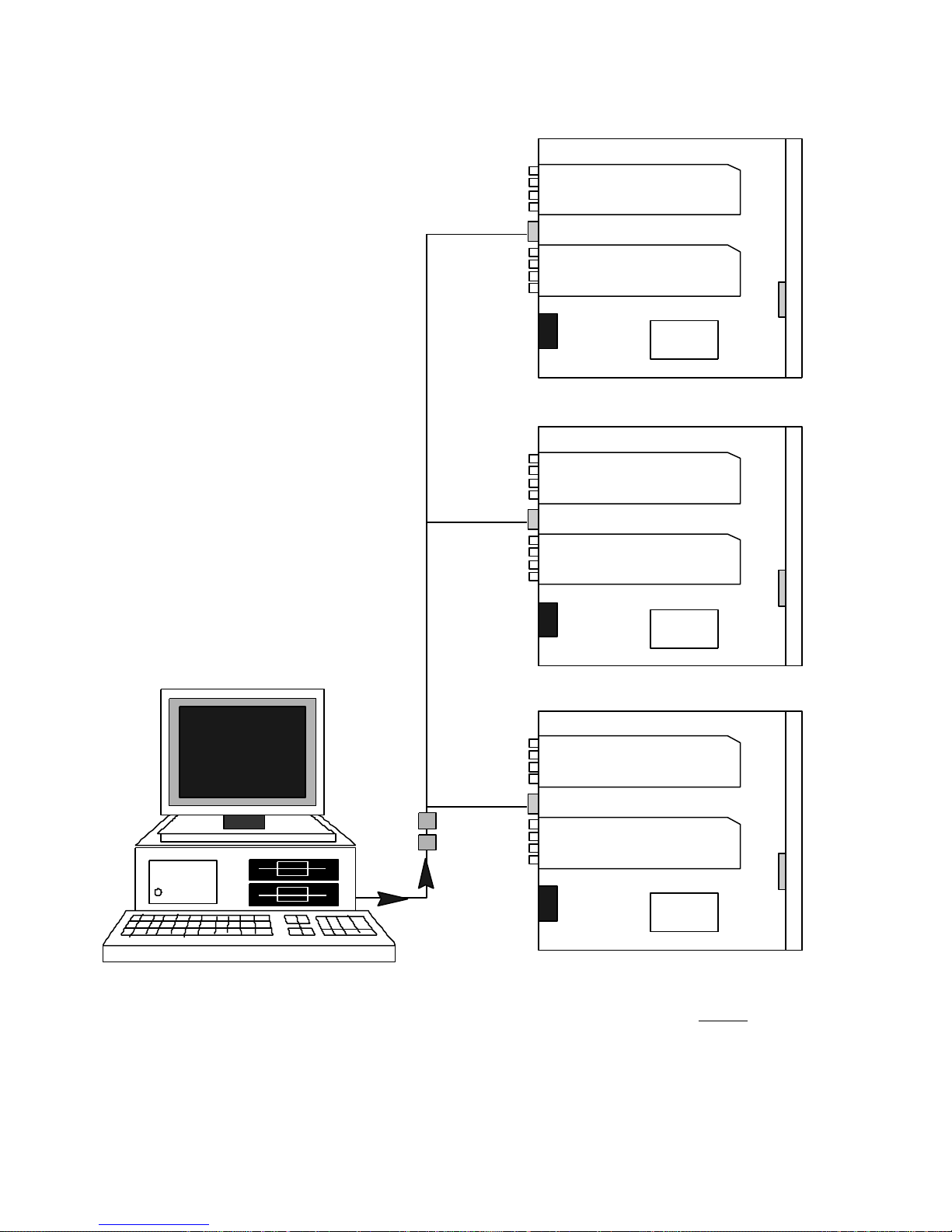
Unit 2
MicroSYNC
MicroSYNC
Routing Switcher
DB-9-M
Ribbon Cable Daisy Chain (User Supplied)
DIP Switches
DIP Switches
DB-9-M
DIP Switches
3 DOWN
4 DOWN
5 DOWN
6 DOWN
7 DOWN
DIP Switches
3 UP
4 UP
5 UP
6 UP
7 UP
DIP Switches
3 DOWN
4 DOWN
5 DOWN
6 UP
7 DOWN
DIP Switches
3 DOWN
4 DOWN
5 DOWN
6 DOWN
7 UP
Unit 1
Power Supply
Unit 4
Unit 3
MicroSYNC
Power Supply
ES-2200T
DIP Switches
1 UP
2 UP
3 UP
4 UP
5 UP
ES-22OOT
DIP Switches
1 UP
2 DOWN
3 DOWN
4 DOWN
5 DOWN
ES-2200 #1 ES-2200 #2 ES-2200 #3
ES-2200S
2 UP
3 UP
4 UP
5 UP
6 UP
ES-2200S
DIP Switches
2 UP
3 DOWN
4 DOWN
5 DOWN
6 DOWN
Unit 6
V-Scope
DB-9-M
DB-9-F
DB-9-F
RS-232 Cable
DIP Switches
3 DOWN
4 DOWN
5 DOWN
6 UP
7 UP
Unit 5
MicroSYNC
Power Supply
(Customer Supplied)
Computer Control
Figure 5-4: Controlling Three ES-2200 Units
ES-2200T
DIP Switches
1 UP
2 UP
3 DOWN
4 DOWN
5 DOWN
ES-2200S
2 UP
3 UP
4 DOWN
5 DOWN
6 DOWN
54
Page 56

Appendices
55
Page 57

Appendix A: Specifications
Serial Data Input
Level RS-232
Baud Rate defaults to 9600 BPS
Interface DB-9 Female
Receive Pin 3
Ground Pin 5
Power Requirements
Input Voltage 100-240 VAC 50/60 Hz
Input Power 5.0 Watts (Basic ES-2200 chassis)
40 Watts (Maximum with two cards installed)
WARNING
This unit must be connected to earth ground in order to ensure compliance with EMI and safety regulations. Also, this
unit contains voltages dangerous to life and must only be serviced by qualified personnel.
Physical Characteristics
Dimensions 17" (43.2 cm) wide by
1-3/4" (4.4 cm) high by
20" (50.8 cm) deep.
Weight 7 lbs. (15.4 Kg)
Operating Environment 0 to 40 ° C.
Spec Temperature 10 to 40 ° C.
Storage Temperature -40 to 75° C.
56
Page 58

Appendix B: Serial Protocol
This section describes the serial data interface to the ES-2200. The information presented here is intended for
users/programmers who want to develop their own custom driver software for the ES-2200. DPS has developed DOS
and AMIGA software that is normally included with every purchase of a Personal TBC IV/ TBC III card or a Personal
V-SCOPE card. Also, PC software is available for the MicroSYNC and the Personal Routing Switcher card. The same
software can be used to remote control the ES-2200. If the ES-2200 was purchased with any of the above cards
installed (i.e. TBC IV or V-Scope etc.) then a copy of the software along with software manuals will be included with
the unit. This software can be used to remote control the ES-2200 the same way it controls an individual card.
Electrical Interface
The electrical interface is RS-232. The bit rate will be 31,250 BPS or 9,600 BPS (DIP Switch selectable), with 8 data
bits, 1 stop bit, no parity. The pin-out for the remote data input on the ES-2200 is explained below:
Connector Type: DB 9 Female
PIN 3 RS-232 In
PIN 5 Ground
Protocol
The software protocol is a MIDI compatible format, using the system exclusive feature of the MIDI interface.
Communication with the ES-2200 is initiated when the system exclusive command byte (F0 Hex) is received, followed
by the unit ID code (67 Hex). The unit ID is 67 Hex for all DPS products.
The next byte sent is the unit address byte (TBC/ MicroSYNC/ Switcher) or the V-SCOPE address byte, which
determines which DPS card is being addressed by the command. This is followed by a unit function byte, and 1 or
more data bytes. The Data byte(s) is send in ASCII for all the cards except for the V-Scope it should be sent in binary.
The communications is completed when the MIDI end system exclusive byte is sent (F7 Hex). The following table
summarizes the protocol:
HOST: System Exclusive Byte (=F0 Hex)
UNIT ID Byte (=67 Hex)
UNIT Address Byte (=40 Hex, 00-0F Hex - or =10 Hex for a V-Scope)
Function Select Byte (= 00-7F Hex)
Data Byte 1 (ASCII..Binary if V-Scope)
Data Byte 2 (ASCII..Binary if V-Scope)
End System Exclusive (= F7 Hex)
System Exclusive Byte
This byte is used in the MIDI protocol to allow manufacturers of MIDI equipment to define messages specific to their
own equipment. The system exclusive mode remains in effect until the end system exclusive command is sent.
57
Page 59

TBC/MicroSYNC/V-Scope ID Byte
This byte is the unique code that precedes the exclusive data that identifies DPS products.
Unit Address Byte
This Byte determines which card the following command is directed to. Every TBC IV, Switcher and MicroSYNC card
has five DIP Switches that are normally used to determine the card address. Refer to the installed cards' operator's
manuals on how to set the cards’ addresses. Cards installed in different ES-2200s must each have a unique address.
There are thirty-two possible addresses that could be assigned to each TBC IV or MicroSYNC card. It is up to the user
to assign a unique address to each TBC, Switcher or MicroSYNC installed inside an ES-2200. There are three rules that
must be followed when setting a card address inside an ES-2200:
The Address of the ES-2200 must be set to the same address as the card installed in the UNIT 1 slot. Set DIP Switches
5, 4, 3, 2 and 1on the ES-2200T front panel or DIP Switches 6, 5, 4, 3 and 2 on the
ES-2200S in same direction as DIP Switches 3, 4, 5, 6 and 7 respectively on the card installed in the UNIT 1 slot
(except V-Scopes). For example, if the card in the UNIT 1 slot had its DIP Switches set to:
3 UP
4 DOWN
5 DOWN
6 DOWN
7 DOWN
Then the switches inside the front of the ES-2200T chassis should be set to:
1 DOWN
2 DOWN
3 DOWN
4 DOWN
5 UP
Or the switches inside the front of the ES-2200S chassis should be set to:
2 DOWN
3 DOWN
4 DOWN
5 DOWN
6 UP
The address of the card installed in the UNIT 2 slot must be one address greater than that of the card installed in the
UNIT 1 slot.
The Baud rate of the all the cards and of the ES-2200 front panel should be the same. The Default factory setting is
9600 BPS.
Unlike the TBC, Switcher or MicroSYNC cards, all V-SCOPES respond to address byte 10 Hex. Therefore all
V-SCOPES in a system will respond to any V-SCOPE command regardless of the ES-2200 address. Only one
V-SCOPE can be installed in the ES-2200. V-Scopes should be installed in the UNIT 2 slot only. Contact DPS if you
require two V-Scopes with independent addresses in one ES-2200.
58
Page 60

TBC/MicroSYNC Function Select/Data
Byte(s)
The function byte determines which function on the addressed TBC card will be effected by the command. Most
commands follow this byte with two characters that represent the new Hex value for the selected function. The table
below lists each function, and the associated data bytes:
Function ByteData Byte(s) Description
01 hex 2 (0,0-F,F) Set video level command
00= Minimum video level
FF= Maximum video level
02 hex 2 (0,0-F,F) Set black level command
00 = Minimum black level
FF = Maximum black level
03 hex 2 (0,0-F,F) Set chroma level command
00 = Minimum chroma level
FF = Maximum chroma level
04 hex 2 (0,0-F,F) Set hue command
00 = Maximum counter clockwise
FF = Minimum clockwise
05 hex 2 (0,0-F,F) Set Genlock timing fine (0.55 ns/increment)
00 = Most Retarded setting
FF = Most Advanced setting
06 hex 2 (0,0-3,F) Set Genlock timing coarse (140nsec/increment)
00 = Most retarded setting
3F = M ost Advanced setting
07 hex 2 (0,0-F,F) Set Horizontal position
00 = Most retarded setting
FF = Most Advanced setting
08 hex 1 (0-1) Input mode Select
0 = NTSC input mode
1 = SVHS input mode
0C hex 1 (0-1) Freeze/Live mode select
0 = LIVE mode
1 = FREEZE mode
10 hex 2 (0,0-F,F) Set Blue color correction
00 = Most Neg Blue correction
80 = No Blue correction
FF = Most Pos Blue correction
11 hex 2 (0,0-F,F) Set Red color correction
00 = Most Neg Red correction
80 = No Red correction
FF = Most Pos Red correction
59
Page 61

12 hex 2 (0,0-F,F) Set Strobe Rate (in Frames)
00 = Full Motion
01 = Fastest Strobe
7F = Slowest Strobe
13 hex 1 (0-2) Select Freeze Mode
0 = Frame Mode
1 = Field Mode
2 = Strobe Mode
(Valid for MicroSYNC cards only) 3= 4-Field Mode
(Valid for TBC IV cards only) 4= Film Mode
14 hex 1 (0-2) Freeze Field Select
0 = Select Field 1
1 = Select Field 2
2 = Select Field 3
3 = Select Field 4 ...MicroSYNC only
4 = Select Field 5 ...MicroSYNC only
16hex 1 (0-F) Y/C Delay horizontal
0 = +570nS
8 = 0
F = -490nS
24hex 1 (0-3) Y/C Delay vertical
0 = +1 line
1 = 0
2 = -1 line
3 = -2 lines
25 hex 1 (0-1) Set Monochrome Mode
0 = Monochrome Mode Off
1 = Monochrome Mode On (Chroma OFF)
32 hex 2 (0,0-F,F) Set MicroSYNC Options BYTE #1
See Section below for MicroSYNC Configuration
33 hex 2 (0,0-F,F) Set MicroSYNC Options BYTE #2
See Section below for MicroSYNC Configuration
34 hex 1 (0-1) Set Frame freeze
0 = Select Frame 1
(Command valid for MicroSYNC only) 1 = Select Frame 2
35 hex 2 (0,0-F,F) Set TBC IV Configuration BYTE #1
See Section below for TBC IV Configuration.
36 hex 2 (0,0-F,F) Set TBC IV Configuration BYTE #2
See Section below for TBC IV Configuration.
60
Page 62

MicroSYNC Configuration Bytes
There are two bytes that carry all of the MicroSYNC Configuration information.
Configuration Byte #1 Configuration Byte #2
Bit 0 Vertical Blanking Bit 0 Genlock Mode
0 = Narrow 0 = Auto
1 = Wide 1 = Manual
Bit 1 Synchronizer Mode Bit 1 Manual Genlock Mode
0 = 4-Field 0 = Exte rnal
1 = Frame 1 = Internal
Bit 2 Output Burst Bit 2 Comb Filter Mode
0 = Burst ON 0 = Normal
1 = Burst Off 1 = Monochrome
Bit 3 Manual Burst Bit 3 Input Lock Mode
0 = ON 0 = Auto Lock
1 = OFF 1 = Manual Lock
Bit 4 Process Bit 4 Manual Input Lock
0 = Process 0 = Burst Lock
1 = Bypass 1 = Manual Lock
Bit 5 Hot Switch Bit 5 Clamp Speed
0 = Enable 0 = Normal
1 = Disable 1 = Fast
Bit 6 Hot switch Mode Bit 6 Forced Black Mode
0 = Frame 0 = Normal
1 = Black 1 = Black
Bit 7 Black Clip Bit 7 Hot Frame Mode
0 = Enable 0 = Off
1 = Disable 1 = On
61
Page 63

TBC IV Configuration Bytes
There are two bytes that carry all of the MicroSYNC Configuration information.
Configuration Byte #1 Configuration Byte #2
Bit 0 Input Mode Bit 0 Force Black
0 = NTSC 0 = Normal
1 = SVHS 1 = Force Black
Bit 1 Monochrome Mode
0 = Chroma ON
1 = Chroma Off
Bit 2 Comb Filter
0 = ON
1 = Off
Bit 3 Reference Termination
0 = Open
1 = 75 Ohm
Bit 4 Vertical Blanking
0 = Narrow
1 = Wide
Bit 5 Genlock Mode
0 = Int
1 = Auto
Bit 6 Hot Switch
0 = Disable
1 = Enable
Bit 7 Burst Enable
0 = Enable
1 = Disable
62
Page 64

V-SCOPE Function Select Byte/Data
Byte(s)
The function byte determines which function on the addressed V-SCOPE card will be effected by the command. Most
commands follow this byte with one data byte, which represents the new binary value for the selected function. The
table below lists each function, and the associated data byte:
Function ByteData Byte(s) Description
01 hex 1 (0-2) Set V-SCOPE mode.
00 = Vector Scope mode.
01 = Waveform Display mode.
02 = Overlay Vector/Waveform mode.
03 = Split Screen Vector/Waveform mode.
02 hex 1 (0-1) Superimpose Output control.
00 = Superimpose mode OFF.
01 = Superimpose mode ON.
03 hex 1 (0-1) 1-H/2-H Waveform mode default select.
00 = 1-H Waveform mode.
01 = 2-H Waveform mode.
04 hex 2 (0-3,02-127) First Byte: Trace Update mode select.
Second Byte: Trace rate (used in mode 3)
0 = Normal.
1 = Freeze Trace.
2 = Peak Hold mode.
3 = Variable rate select.
05 hex 1 (0-1) Frequency response select.
0 = Flat response.
1 = Low Pall (Luma) response.
For command 04, (Trace mode select) the second byte is used to select the trace update rate (in frames), and will be
used whenever mode 3 is selected via the first byte. However, the second byte must always be transmitted no matter
which mode is being selected. Selecting a slower update rate (by increasing the value) will cause the display to fill in
more fully. The default update rate (used in normal mode) is 2 frames.
63
Page 65

Appendix C: Important Addresses
and Phone Numbers
INTERNET
ftp://ftp.dps.com
http://www.dps.com
Support E-mail:
Canada/International [email protected]
U.S [email protected]
Europe [email protected]
Asia-Pacific [email protected]
Suggestions: [email protected]
CANADA/INTERNATIONAL
Digital Processing Systems, Inc.
70 Valleywood Drive
Markham, Ontario L3R 4T5
Toll Free: 800-775-3314
Voice: 905-944-4000
Fax: 905-944-4200
Customer Service Voice Mail: 905-944-4100
USA
Digital Processing Systems, Inc.
11 Spiral Drive, Suite 10
Florence, KY 41042
Toll Free: 800-775-3314
Voice: 859-371-5533
Fax: 859-371-3729
64
Page 66

EUROPE
Digital Processing Systems, Ltd.
Romans Business Park, Unit 9
East Street, Farnham
Surrey, GU9 7SX
U.K.
Phone numbers are preceded by +44 1252 if calling from outside the U.K. and by 01252 if calling from inside the U.K.:
Voice: 718300
Fax: 718400
BBS: 723790
ASIA AND THE PACIFIC RIM
DPS Asia Pacific
858 King Goerges Road
South Hurstville, Sydney
N.S.W., 2221
Australia
Voice: 61-2-9547-0088
Fax: 61-2-9547-0988
65
Page 67

Appendix D: A Brief History of DPS
We were originally founded in 1975 as Digital Video Systems. DVS was a pioneer in the development of time base
correctors (TBCs) and synchronizers. The company’s first product, the DVS1 Time Base Corrector, was sufficiently
ahead of its time that many of them are still being used today.
DVS was acquired by Scientific Atlanta in 1982 and the focus of the division shifted to satellite encryption
technologies. In 1988, the studio video product line was spun off into a new employee-owned company called Digital
Processing Systems (DPS). In 1996 DPS went public, with a very successful initial public offering (IPO) of over three
million shares.
Today, while DPS continues to innovate and expand its line of traditional broadcast products, the company experiences
significant growth in the computer video marketplace. DPS entered the computer video field in 1991 with the
introduction of the DPS Personal TBC, the first infinite window TBC on a PC card. The DPS Personal TBCs
combination of features, performance and price was unique, and competed with units selling for three times its cost.
After the success of this TBC card, DPS followed with the Personal TBC II, III and IV, each of which provided
increased features and performance. Another innovation was the DPS Personal V-Scope, the world’s first combination
waveform monitor/vector scope on a PC card.
The DPS Personal Animation Recorder (PAR), a plug-in card which functions as a single-frame recording deck, was
introduced soon after the first Personal TBC and quickly became one of our most popular products. Still selling in both
PC and Amiga versions — a testament to how far ahead of the rest of the industry it was — the PAR provides
component analog video (Betacam, MII), composite and S-Video (Hi-8/SVHS) outputs.
The DPS Perception Video Recorder (PVR) is a significant advancement beyond the PAR. First shipped in 1995, the
multiple-award-winning PVR is a PCI-bus digital video disk recorder which features 10-bit video encoding with 2X
oversampling, CCIR 601 4:2:2 processing and an integrated SCSI-2 hard drive controller. The PVR is also designed to
integrate with third-party non-linear editing software.
Fulfilling the promise of the PVR to be “the heart of an advanced digital video workstation,” DPS has built a family of
products that work with the PVR to create a complete video-audio editing solution. These products include the AD2500/3500 Component Video Capture daughter card; the SD-2500/3500 Serial Digital Video I/O card; the Perception
F/X transition effects accelerator card; and the Perception Audio for Video (A4V) board.
A key contributor to the quality and remarkable capabilities of DPS’s computer video products has been our lengthy
experience in the broadcast studio field, and our traditional broadcast product line is still going strong. In the last yearand-a-half alone we introduced the DPS MicroSYNC-X 10-bit four-field video synchronizer card; the DPS
MicroSYNC-AVX stereo audio/video synchronizer system; and the DPS-465 Serial Digital Video Synchronizer.
Digital Processing Systems’ corporate headquarters and manufacturing facilities are in Toronto, Canada. Sales, service
and distribution facilities for the United States are located in Florence, KY, adjacent to the Greater Cincinnati/Northern
Kentucky Airport. A United Kingdom office oversees European operations from London, and Asia and Pacific Rim
countries are serviced by our office in Sydney, Australia.
66
Page 68

Appendix E: Warranty
Warranty Statement
Digital Processing Systems, Inc., warrants the original purchaser that this product is in good working condition for a
period of two years from the date of purchase. Should this product, in Digital Processing System’s opinion, malfunction
within the warranty period, Digital Processing Systems, Inc., will repair or replace this product without charge. This
warranty does not apply to those products that have been damaged due to accident, unauthorized alterations, repairs or
modifications.
Warranty Limitations
All warranties for this product, expressed or implied, are limited to two years from the date of purchase and no
warranties, expressed or implied, will apply after that period.
The distributor, its dealers and customers agree that Digital Processing Systems, Inc., shall not be liable for any loss of
use, revenue or profit.
Digital Processing Systems, Inc., makes no other representations of warranty as to fitness for purpose of
merchantability or otherwise in respect to any of the products sold to the distributor pursuant to this agreement.
The liability of Digital Processing Systems, Inc., in respect of any defective products will be limited to the repair or
replacement of such products.
In no event shall Digital Processing Systems, Inc., be responsible or liable for any damages arising from the use of such
defective products whether such damages be direct, indirect, consequential or otherwise and whether such damages are
incurred by the distributor or third party.
67
Page 69

Warranty Service
Units requiring repair under warranty may be sent directly to Digital Processing Systems, Inc. To obtain service under
this warranty, first contact the Digital Processing Systems Customer Service Department to request a Return Material
Authorization (RMA) Number.
• Canada and International (Country code) 905.944.4000
• USA (Country code) 859.371.5533
• Europe +44 1252 (outside the UK) or 01252 (inside the UK) followed by 718300
• Asia - Pacific Rim 61.2.9547.0088
The RMA number must be clearly displayed on the unit’s external packaging. Units shipped without this number will
not be accepted. Include proof of purchase (including date of purchase), a note outlining the problem and the RMA
number.
IMPORTANT: When shipping your unit, pack it securely and ship prepaid and insured. Digital
Processing Systems, Inc., will not be held liable for damage or loss to the product in shipment.
Repaired items will be returned to the purchaser prepaid via a surface freight carrier of DPS’ choice
(within the continental United States). If another method of shipping is desired, it must be clearly
specified in writing and all priority return freight charges are the responsibility of the purchaser.
68
Page 70

Appendix F: Compliance
FCC Compliance Statement
This device complies with Part 15 of the FCC rules.
Operation is subject to the following two conditions:
(1) This device may not cause harmful interference, and
(2) This device must accept any interference received,
including interference that may cause undesired operation.
NOTE: This equipment has been tested and found to comply with the limits
for a Class A digital device pursuant to Part 15 of FCC Rules. These limits
are designed to provide reasonable protection against harmful interference
when this equipment is operated in a commercial environment. This
equipment generates, uses, and can radiate radio frequency energy and, if not
installed and used in accordance with the instruction manual, may cause
harmful interference to radio communications. Operation of this equipment
in a residential area is likely to cause harmful interference, in which case the
user will be required to correct the interference at his or her own expense.
69
 Loading...