

Broadata Communications LBC-PSW84 User Manual
LBC-PSW84
LINK BRIDGETM MULTI-FORMAT
PRESENTATION SWITCH
BCI reserves the right to make changes to the products described herein without prior
notice or consent. No liability is assumed as a result of their use or application. All
©2013 Broadata Communications, Inc.
rights reserved.

LBC-PSW84 User’s Manual
Link Bridge
TM
Multi-format Presentation Switch
SAFETY INSTRUCTIONS AND
COMPLIANCE DECLARA TIONS
PLEASE OBSERVE THE FOLLOWING SAFETY
PRECAUTIONS
SURGE PROTECTION DEVICE RECOMMENDED
This product contains sensitive electrical components that may be
damaged by electrical spikes, surges, electric shock, lightning strikes,
etc. Use of surge protection systems is highly recommended in order
to protect and extend the life of your equipment.
Broadata Technical Support, Sales@Broadatacom.com
3

LBC-PSW84 User’s Manual
Link Bridge
TM
Multi-format Presentation Switch
TABLE OF CONTENTS
1.0 PRODUCT DESCRIPTION ..............................................5
2.0 OPERATION CONTROLS AND FUNCTIONS .................7
2.1 FRONT PANEL .................................................................7
2.2 REAR P ANEL ...................................................................8
2.3 REMOTE CONTROL......................................................10
3.0 ON SCREEN DISPLAY...................................................11
3.1 MAIN MENU SELECTION ..............................................11
3.2 COLOR ...........................................................................12
3.3 AUDIO .............................................................................13
3.4 SETUP............................................................................14
3.5 INFORMA TION................................................................15
4.0 CONNECTOR PIN ASSIGNMENT.................................16
4.1 IR PIN ASSIGNMENT .....................................................16
4.2 RS-232 PIN ASSIGNMENT.............................................17
5.0 DC POWER CONNECTION...........................................18
6.0 MAINTENANCE AND TROUBLESHOOTING ...............2 0
6.1 MAINTENANCE ..............................................................20
6.2 TROUBLESHOOTING ................................................... 20
7.0 SPECIFICA TIONS...........................................................22
8.0 SERVICE PROCEDURE ................................................23
8.1 REPLACEMENT POLICY ..............................................23
8.2 RETURN AND REPAIR SERVICE .................................23
9.0 LIMITED WARRANTY ....................................................24
10.0 APPENDIX A .................................................................25
11.0 APPENDIX B..................................................................28
4
Broadata Technical Support, (800) 214-0222

LBC-PSW84 User’s Manual
Link Bridge
TM
Multi-format Presentation Switch
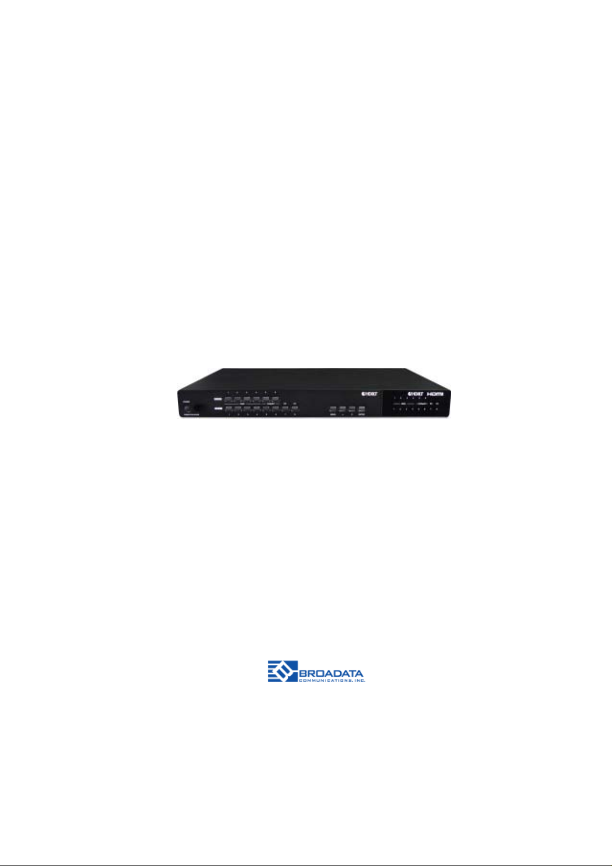
1.0 PRODUCT DESCRIPTION
The LBC-PSW84 is an HDBaseT™ capable 8 by 4 Digital Presentation
Scaler that can switch and scale HDMI/HDBaseT/PC/Composite Video
signals from any one of its eight inputs and simultaneously display it on
any of its HMDI or HDBaseT outputs. The unit supports four (4) HDMI
input, one (1) VGA input, one (1) composite input and two (2) HDBaseT
inputs. The unit has an HDMI bypass output, allowing local monitoring
of any of the HDMI or HDBaseT inputs, VGA and composite are not
supported by the bypass output.
It has the added benefit of control via IR remote control, RS-232, IP/T elnet
and WebGUI, with all information including system status presented on
its comprehensive OSD (On Screen Display).
The LBC-PSW84 features full 5play™ compliance for easy integration
with compatible transmitters and receivers. The LBC-PSW84 is
compatible with our Designer and St andard (LBH & LBC model) Series
transmitters and receivers. This makes both CAT-5e/6 transmission
and HDMI/DVI/VGA/YPbPrI conversion in one single system setup.
The units are easily monitored by a power/ link LED indicators.
Figures 1-1, and 1-2 below illustrate the front and rear panels of the
LBC-PSW84 unit and Figure 1-3 shows the remote control.
Features
• HDMI, HDCP and DVI compliant
• Full 5Play™ compliant: Video, Audio, LAN, and Control (IR &
RS-232 bypass)
• Supports Power over HDBaseT (PoH) on the CAT5e/6/7
output to a compatible Receiver. HDBaseT inputs do not
support PoH
• Supports High-definition Audio: LPCM 7.1CH, Dolby TrueHD,
Dolby Digital Plus and DTS-HD Master Audio transmission
(32-192kHz sample rate)
• Supports distances of up to 100 meters on the output and
100m on the input over industry standard CA T5e/6/7 cable
• Supports scaling of any input signals to a wide range of HDTV
and PC output resolutions up to 1080p and WUXGA (RB)
Broadata Technical Support, Sales@Broadatacom.com
5

LBC-PSW84 User’s Manual
Link Bridge
TM
Multi-format Presentation Switch
• Simultaneous video output of the selected source through the
HDBaseT and HDMI outputs and audio output through the
digital coaxial and analog L/R outputs
• Features four HDMI inputs with corresponding L/R audio
inputs (3.5mm mini-jack), two HDBaseT CAT5e/6/7 inputs, PC
(15-pin D-Sub) with L/R audio (3.5mm mini-jack) and
Composite Video and L/R audio (3 RCA)
• Features two HDMI outputs, one HDBaseT CAT5e/6/7 output,
one Digital Coaxial audio output and one L/R audio 3.5mm
mini-jack output
• Supports a switchable HDMI scaler bypass output, allowing
local monitoring of any of the HDMI or HDBaseT inputs, VGA
and composite inputs are not supported by this output.
• Supports control via IR, Remote control, local RS-232,
T elnet WebGUI and on-p anel controls
• Supports HDBaseT LAN pass-through function to compatible
Receivers
Package Contents
• 1 x 8 by 4 Presentation Switch w/ Scaler
• 1 x IR Extender cable
• 1 x IR Receiver cable
• 1 x Remote Control w/ battery
• 1 x 24v/2.7A DC Power Adapter
• 1 x Power Cord
• User’s Manual
6
Broadata Technical Support, (800) 214-0222

LBC-PSW84 User’s Manual
Link Bridge
TM
Multi-format Presentation Switch
2.0 OPERA TION CONTROLS AND FUNCTIONS
2.1 Front Panel
4
1
2
3
5
7
6
9
8
10
4
3
5
1. POWER: Press this button to turn ON the device and the LED
will illuminate.
2. IR Window: This IR receiver receives only the remote control
signal from the packaged remote control.
3. INPUT HDMI 1~4 & LED: Press the IN buttons to select an
input source signal from the 4 HDMI input sources to be
display for output ports. The LED will illuminate according to
the selection.
4. BYP ASS & LED: Press these buttons to select an input
source signal from the 6 input sources to be displayed for
BYP ASS output port. The LED will illuminate according to the
selection.
5. INPUT CAT5e/6/7 5~6 & LED: Press the IN buttons to select
an input source signal from the 2 CA T5e/6/7 input sources to
be display for output ports. The LED will illuminate according
to the selection.
6. INPUT VGA & LED: Press this button to select VGA input
source signal to be display for VGA output port. The LED will
illuminate according to the selection.
7. INPUT CV & LED: Press this button to select CV input
source signal s to be display for CV output port. The LED
will illuminate according to the selection.
8. MENU: Press this wheel to enter into the menu and press it
again to confirm the selection.
7
6
Broadata Technical Support, Sales@Broadatacom.com
7
LBC-PSW84 User’s Manual
Link Bridge
TM
Multi-format Presentation Switch
9. +/-: Press these buttons to move up/down under menu
selection or under volume control to adjust audio volume up/
down.
ENTER: Press this button to confirm menu selection
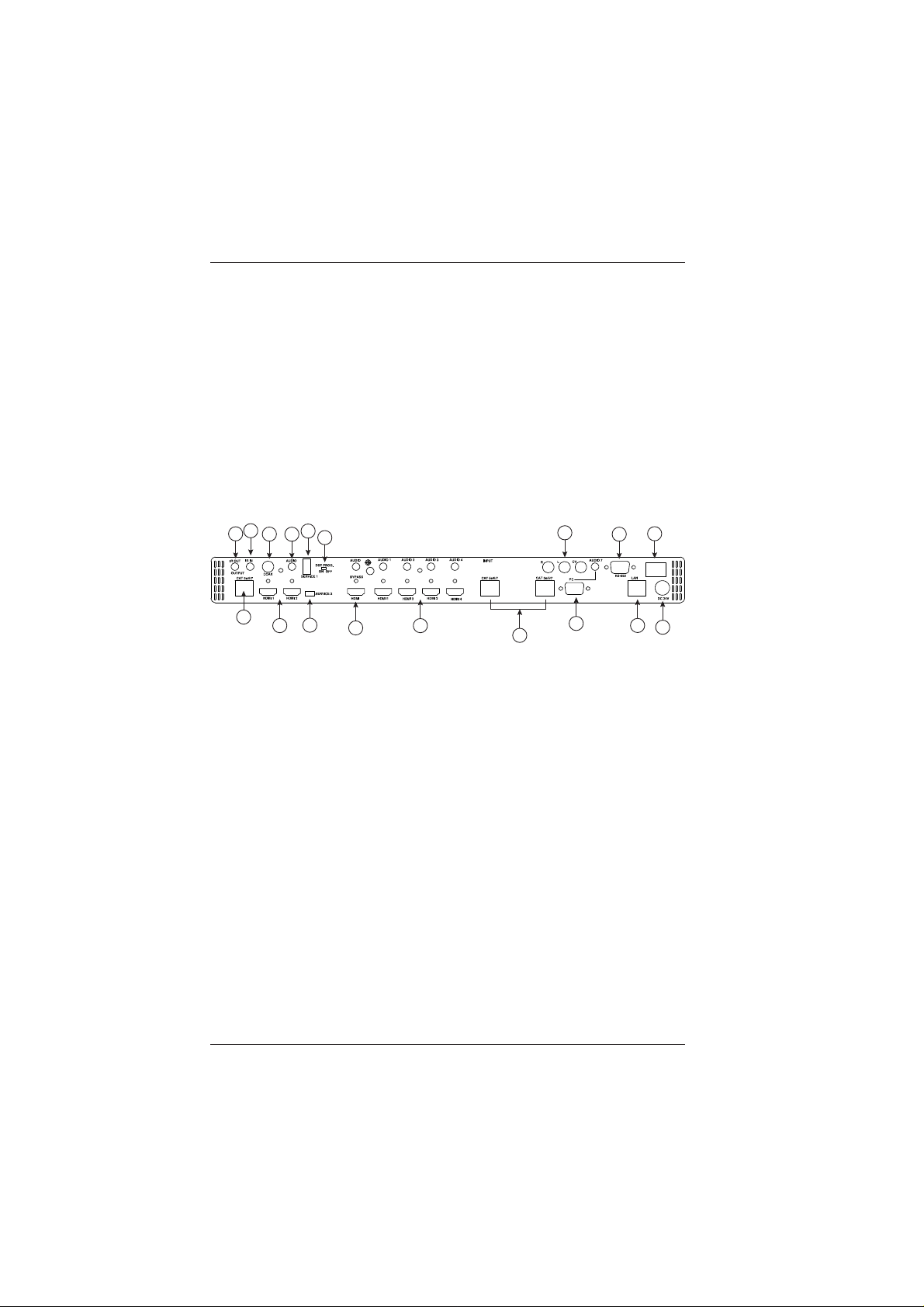
2.2 Rear Panel
2
1
3
7
5
6
8
7
4
9
10
13
11
12
16
14
15
1. IR OUT: Connect to the supplied IR Blaster cable for IR signal
transmission. Place the IR Blaster in direct line-of-sight of the
equipment to be controlled.
2. IR IN: Connect to the supplied IR Extender cable for IR signal
reception. Ensure that remote being used is within the direct
line-of-sight of the IR Extender.
3. OUTPUT CA T5e/6/7: Connect to the Receiver unit with a Single
CA T5e/6/7 cable for transmission of all data signals.
4. OUTPUT HDMI: Connect to a HDMI equipped TV/monitor for
display of the HDMI input source signal.
5. OUTPUT COAX: Connect to audio sound equipment such as
speaker or amplifier for audio sound output.
6. OUTPUT AUDIO: Connect to audio sound equipment such as
speaker or amplifier for audio sound output. This audio is
extracted from the video output. The source for this audio is
dependent upon the selected mode from the OSD. If in ‘Auto’
mode then the source audio is derived from the input HDMI
embedded audio. If in ‘EXT’ mode the audio is sourced from
the external input audio.
17
8
Broadata Technical Support, (800) 214-0222

LBC-PSW84 User’s Manual
Link Bridge
TM
Multi-format Presentation Switch
7. SERVICE 1& 2: These slots are reserved for firmware update
use only.
8. DSP PROG Switch: This switch is reserved for firmware update
use only.
9. BYPASS OUTPUT: Connect to a HDMI equipped TV/monitor
or DVI equipped monitor with audio sound equipment such as
speaker for both video and audio output display. This output
bypasses the output scalar and directly follows the resolution
of the selected input. The Bypass audio connector does not
extract or de-embed audio from the HDMI video. The Bypass
audio is only sourced from the external audio inputs. The
embedded audio on the Bypass HDMI video is only sourced
from the embedded audio on the HDMI video inputs.
10. INPUT HDMI 1~4 & AUDIO 1~4: Connect to HDMI source
equipment such as DVD or Blu-ray player along or to DVI source
equipment along with audio source signal.
11. INPUT CAT5e/6/7: Connect this port to HDMI to CAT5e/6/7
Transmitter with CAT5e/6/7 cable to extend the signal up to
100m.
12. INPUT PC & AUDIO: Connect this port to PC/Laptop with audio
signal for input signal selecting. . The PC (VGA) input does not
support YPbPr video format
13. INPUT CV: Connect this port to source equipment such as video
player or Set-Top-Box for input signal selecting.
14. RS-232: Connect from PC/Laptop for RS-232 command sending
to control the device.
15.LAN: Connect from PC/Laptop with active internet service for
Web
16.POWER Toggle: Switch this toggle to turn ON and OFF the
device’s power
17.DC 24V: Connect the adaptor with power cord included in the
package and connect to AC wall outlet for power supply.
Broadata Technical Support, Sales@Broadatacom.com
9
LBC-PSW84 User’s Manual
Link Bridge
TM
Multi-format Presentation Switch
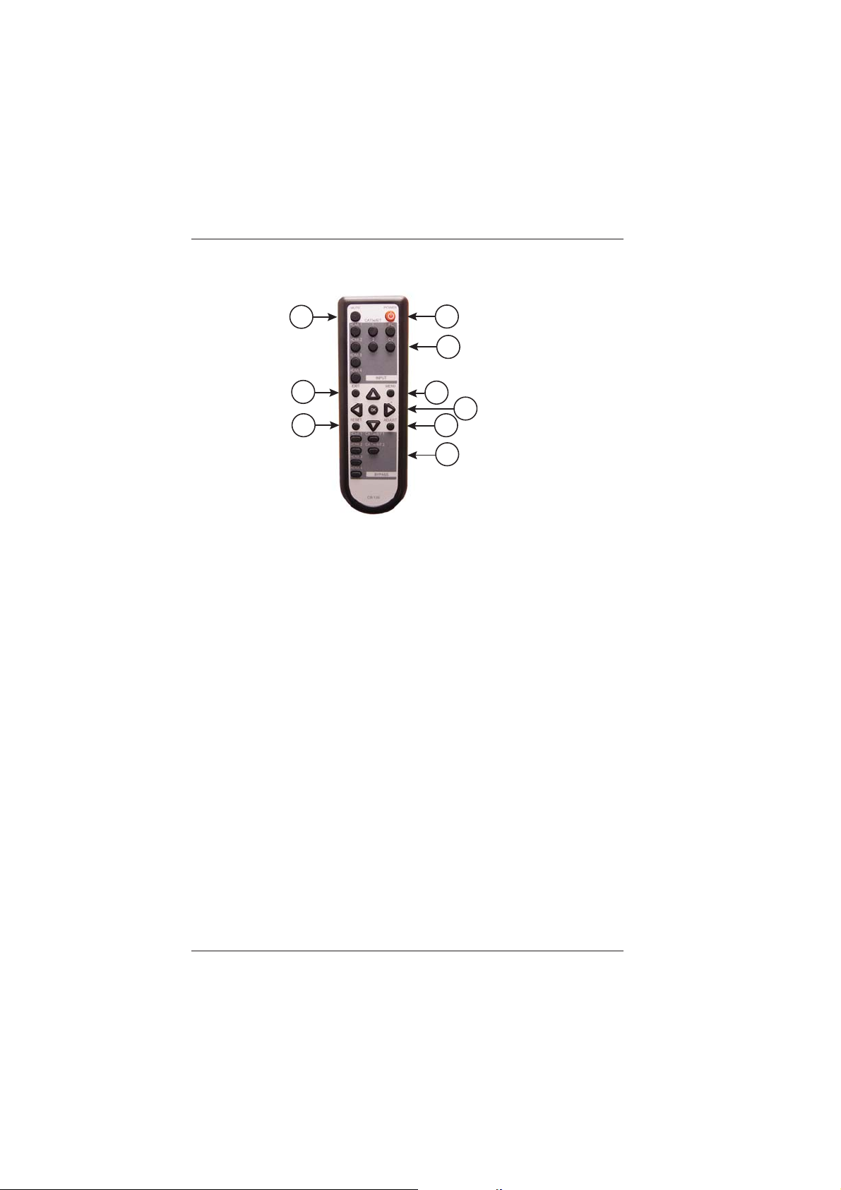
2.3 Remote Control
2
5
8
1
3
4
6
7
9
1. POWER: Press this button to switch the device ON or to put
the device into St andby mode.
2. MUTE: Press this button to mute output audio sound.
3. INPUT: Press these buttons one time each to select input
source for outputs display.
4. MENU: Press this button to enter into the OnScreen Menu.
5. EXIT: Press this button to exit menu selection.
6.
& OK: Press OK to confirm the selection or use the
directional buttons to navigate the On-Screen-Menu.
7. ADJUST : Press this button when output image is not fitting the
display’s screen perfectly . The device will auto adjust the image
to full screen.
8. RESET : Press this button to set the device back into the factory
default setting.
9. BYPASS: Press these buttons to select an input source for
Bypass output port to display.
10
Broadata Technical Support, (800) 214-0222
 Loading...