

Broadata Communications LBC-H-V-T-WP User Manual
LBC-H/V-T-WP
LINK BRIDGETM HDMI/VGA
WALL PLATE TRANSMITTER SYSTEM
BCI reserves the right to make changes to the products described herein without prior
notice or consent. No liability is assumed as a result of their use or application. All
©2013 Broadata Communications, Inc.
rights reserved.

Link Bridge
TM
HDMI/VGA W all Plate Transmitter System
LBC-H/V-T -WP User’s Manual
SAFETY INSTRUCTIONS AND
COMPLIANCE DECLARA TIONS
PLEASE OBSERVE THE FOLLOWING SAFETY
PRECAUTIONS
SURGE PROTECTION DEVICE RECOMMENDED
This product contains sensitive electrical components that may be
damaged by electrical spikes, surges, electric shock, lightning strikes,
etc. Use of surge protection systems is highly recommended in order
to protect and extend the life of your equipment.
Broadata Technical Support, Sales@Broadatacom.com
3

LBC-H/V-T -WP User’s Manual
Link Bridge
TM
HDMI/VGA W all Plate Transmitter System
TABLE OF CONTENTS
1.0 PRODUCT DESCRIPTION ..............................................5
2.0 OPERATION CONTROLS AND FUNCTIONS .................6
2.1 FRONT PANEL .................................................................6
2.2 REAR P ANEL ...................................................................7
3.0 SET UP.............................................................................8
3.1 MOUNTING.......................................................................8
3.2 CABLING AND CONNECTORS.......................................8
3.3 VGA/YPBPR VIDEO INTERFACE ...................................9
3.4 HDMI VIDEO INTERFACE..............................................10
3.5 AUDIO INTERF ACE........................................................1 1
3.6 SERIAL DATA INTERF ACE............................................1 2
3.7 CA T-5E/6 TRANSMISSION CONNECTION ...................13
4.0 DC POWER CONNECTION...........................................14
4.1 IN-WALL POWER/CAT-5E/6 WIRING INSTRUCTION ..15
5.0 MAINTENANCE AND TROUBLESHOOTING ...............18
5.1 MAINTENANCE ..............................................................18
5.2 TROUBLESHOOTING ...................................................18
6.0 SPECIFICA TIONS...........................................................20
7.0 SERVICE PROCEDURE ................................................21
7.1 REPLACEMENT POLICY ..............................................21
7.2 RETURN AND REPAIR SERVICE .................................21
8.0 LIMITED WARRANTY ....................................................22
4
Broadata Technical Support, (800) 214-0222

Link Bridge
TM
HDMI/VGA W all Plate Transmitter System
LBC-H/V-T -WP User’s Manual
1.0 PRODUCT DESCRIPTION
The LBC-H/V-T-WP transmitter is a high performance, low cost,
miniature, Link BridgeTM HDBaseT VGA/HDMI T ransmission System
that embeds the source audio into the VGA video signal. It carries one
(1) unidirectional HDMI video or one VGA/YPbPr signal with one (1) unidirectional embedded stereo audio, and one (1) RS-232 data channel.
This unique CAT 5e/6 transmission system lets your digital flat panel
display extend up to 70m (230 ft) at 4K2K and WUXGA (1920x1200 @
60Hz) or 720p/1080i/1080p HDTV video resolution.
LBC-H/V-T -WP is a 2 gang multi-input wall plate transmitter . When either
the VGA or HDMI with active signal is connected, the signal will be sent
to the compatible HDBaseT receiver automatically. The ‘VGA/HDMI’
button on the wall plate is available for manual signal selection if both
VGA and HDMI with active signal inputs are connected at the same time.
The Wall plate is also capable of being controlled via RS-232 commands
sent by a local RS-232 connection or via a remote HDBaseT receiver . In
addition, the LBC-H/V-T -WP supports PoH (Power over HDBaseT) where
it can be powered by a remote Matrix, a compatible receiver or local DC
adapter.
In addition, the LBC-H/V-T-WP transmitter is compatible with our LBH
and LBC Series receivers. This makes both CA T 5e/6 transmission and
HDMI/DVI/VGA/YPbPrI conversion in one single system setup. The units
are easily monitored by power and link LED indicators. Figures 2-1, and
2-2 illustrate the front and rear panels of the LBC-H/V-T-WP unit.
Broadata Technical Support, Sales@Broadatacom.com
5
LBC-H/V-T -WP User’s Manual
Link Bridge
TM
HDMI/VGA W all Plate Transmitter System
2.0 OPERA TION CONTROLS AND FUNCTIONS
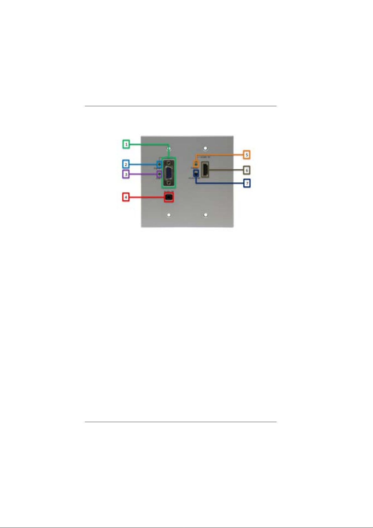
Figure 2-1
LBC-H/V-T-WP Front Panel
1. VGA Input: Connect to VGA source.
2. LED for VGA: LED blinking means there is VGA signal input;
LED always on means current output is VGA.
3. LINK LED for HDBT connection: LED blinking means
CAT-5e/6 cable connection available; LED always on means
there is videosignal input and output.
4. Analog Audio Input: Connect to audio source.
5. LED for HDMI: LED blinking means there is HDMI signal input;
LED always on means current output is HDMI.
6. HDMI Input: Connect to HDMI source.
7. Signal Switch Button: Manual selection of the input signal.
6
Broadata Technical Support, (800) 214-0222
Link Bridge
TM
HDMI/VGA W all Plate Transmitter System
LBC-H/V-T -WP User’s Manual
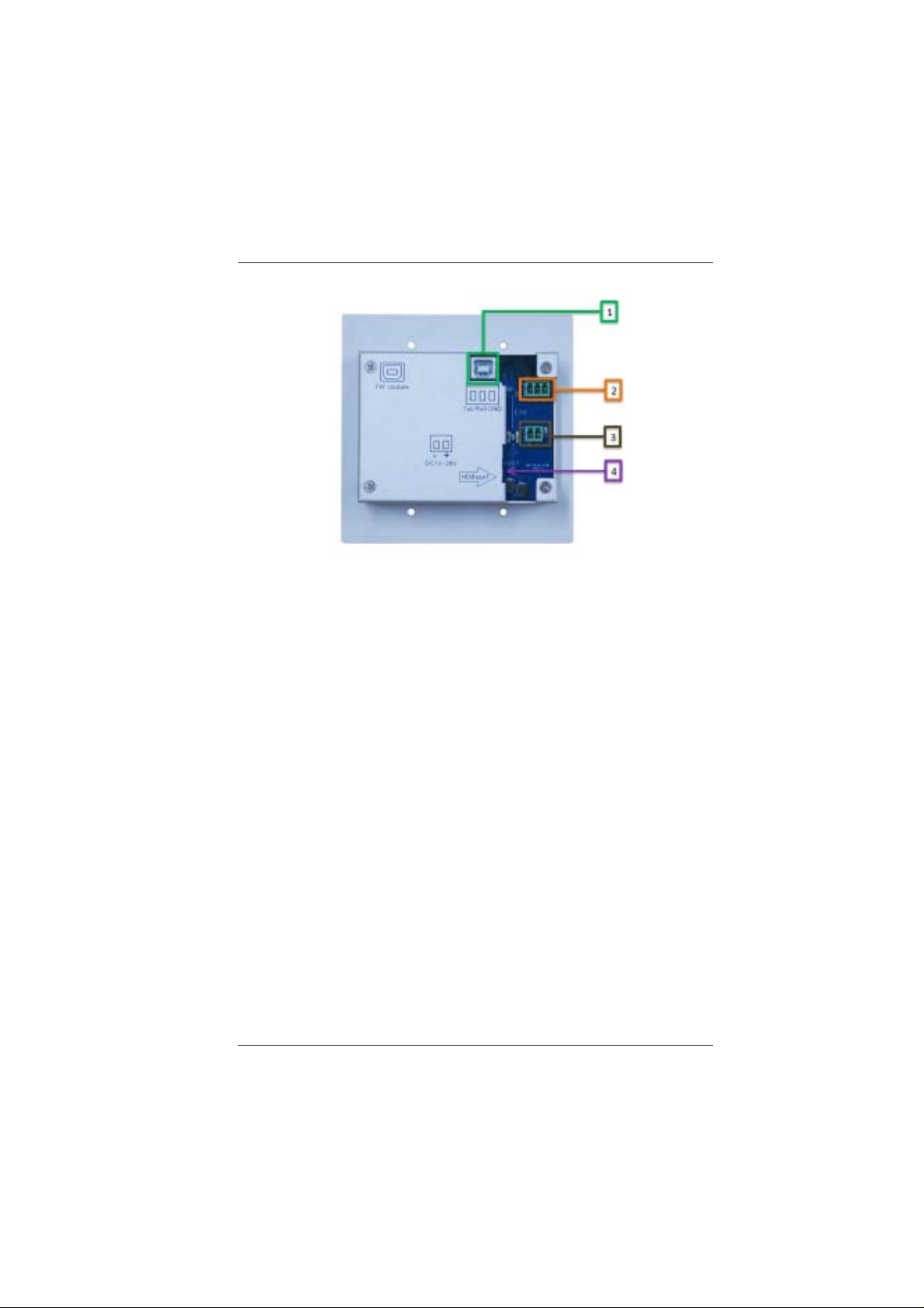
Figure 2-2
LBC-H/V-T-WP Rear Panel
1. Firmware Update USB port
2. RS-232 control port (refer to RS232 protocol on pg 17)
3. Power input
4. HDBaseT CA TX connection
Broadata Technical Support, Sales@Broadatacom.com
7

LBC-H/V-T -WP User’s Manual
Link Bridge
TM
HDMI/VGA W all Plate Transmitter System
3.0 SETUP
The BCI LBC HDBaseT Extender Series units are used in pairs. One
LBC-H/V-T -WP transmitter unit is located at the near-end (source) and
connected through a single category cable, to one of the LBC or LBH
receivers like the LBC-HDBT-R receiver shown below and located at
the far-end (sink) of the link. Figure 3-1 depicts a typical installation for
the LBC-H/V-T -WP and LBC-HDBT -R.
Figure 3-1
LBC-H/V-T-WP with LBC-HDBT-R Transmission Pair
3.1 Mounting
Before installing the units into your housing, make sure there is
enough space to pull and connect both the electrical and category
cables without stressing them beyond the manufacturer’s
limitations (also known as the minimum bend radius).
3.2 Cabling and Connectors
In order to setup the LBC-H/V-T-WP properly, make sure to
observe the following instructions when installing the proper
cables. The LBC-H/V-T-WP requires two parts to the cabling
setup, the video signal and the transmission connections.
8
Broadata Technical Support, (800) 214-0222

Link Bridge
TM
HDMI/VGA W all Plate Transmitter System
LBC-H/V-T -WP User’s Manual
3.3 VGA/YPbPr Video Interface
The RGB/YPbPr video connection is the VGA (HD-15) plug
connectors for video input port. Use the following instructions
to properly connect your component video as illustrated in
Figure 3-2. Connect the LBC-H/V-T-WP (Transmitter) unit’s
RGB/YPbPr video input port to the user’s RGB/YPbPr video
source with the appropriate VGA (HD-15) cables.
Figure 3-2
Connect User’s VGA or YPbPr Video Source
Broadata Technical Support, Sales@Broadatacom.com
9
 Loading...