

Broadata Communications 730E-T User Manual

730E-T Series
FIBER OPTIC
CA TV TRANSMITTER
BCI reserves the right to make changes to the products described herein without
prior notice or consent. No liability is assumed as a result of their use or
application. All rights reserved.
©2008 Broadata Communications, Inc.
BCI 730E User’s Manual
Fiber Optic CATV Transmitter
SAFETY INSTRUCTIONS AND
COMPLIANCE DECLARATIONS
PLEASE OBSERVE THE FOLLOWING SAFETY
PRECAUTIONS AS OUR PRODUCTS CONT AIN
CLASS I LASER PRODUCTS
WARNING
Do not disconnect the fiber optic connector while the unit is powered
up. Exposure to laser radiation is possible when the laser fiber optic
connector is disconnected while the unit is powered up.
Although the fiber optic connectors in this product emit only Class 1
energy that is below the levels considered to be hazardous, one should
never stare directly into a fiber optic connector or an unconnected fiber
end unless one can be certain that no exposure to laser energy could
occur.
CAUTION
This manual is intended for use by trained service personnel. The use
of controls, making adjustments, or performing operations other than
those specified may result in hazardous radiation exposure.
The following label or equivalent is located on the surface of laser products.
This label indicates that the product is classified as a CLASS 1 LASER
PRODUCT.
SURGE PROTECTION DEVICE RECOMMENDED
This product contains sensitive electrical components that may be
damaged by electrical spikes, surges, electric shock, lightning strikes,
etc. Use of surge protection systems is highly recommended in order
to protect and extend the life of your equipment.
Broadata Technical Support, CustomerService@Broadatacom.com
3

BCI 730E User’s Manual
Fiber Optic CATV Transmitter
TABLE OF CONTENTS
1.0 PRODUCT DESCRIPTION ..........................................5
2.0 BLOCK DIAGRAM ........................................................6
2.1 ATC LOOPS .................................................................. 6
2.2 APC LOOPS .................................................................. 7
2.3 RF LOOPS .....................................................................7
2.4 DATA COLLECTION, CONTROL & INTERNET ......... 7
3.0 SPECIFICATIONS .........................................................8
4.0 PANEL ILLUSTRATION ................................................ 9
5.0 INSTALLATION............................................................11
5.1 FIBER CONNECTION ................................................11
5.2 POWER........................................................................11
5.3 LCD DISPLAY.............................................................. 12
6.0 SERVICE PROCEDURE .............................................13
6.1 REPLACEMENT POLICY ...........................................13
6.2 RETURN AND REPAIR SERVICE ..............................13
7.0 LIMITED WARRANTY .................................................14
4
Broadata Technical Support, (800) 214-0222
BCI 730E User’s Manual
Fiber Optic CATV Transmitter
1.0 PRODUCT DESCRIPTION
730E-T is a full-feature direct modulation transmitter for a variety of
architectures, including narrowcast and broadband applications. This
versatile and compact state-of-the-art transmitter has highest quality
cooling DFB laser with isolator, together with APC providing excellent
performance.
Additional features include RF pre-distortion circuitry , a 2-line front panel
user interface provides system status and telemetry and status LED.
LCD shows working status. When working status is abnormal, the display
stops on the wrong item and alarm starts. The Laser power is switched
on/off on the back of the unit. When the laser is off, the AC power can
still be fed into the unit.The system offers maximum value with element
flexibility , as well as front panel RF test point. RS-232 is installed for the
monitor and adjustment by central computer.
High channel capacity , low RF input level, a wide range of output power
and flexible design, coupled with Rayvert ‘s commitment to quality , make
the 730E DFB Laser Transmitter System the ideal solution for your
communications needs.
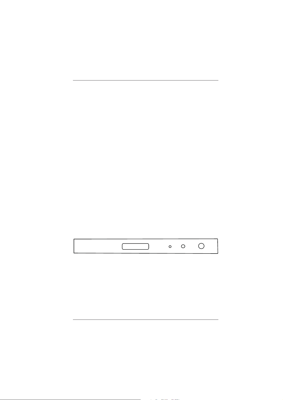
RF TEST
1310nm
AM Laser Transmitter
LASER
SELECT
Figure 1-1
730E-T Front Panel
Broadata Technical Support, CustomerService@Broadatacom.com
5

BCI 730E User’s Manual
Fiber Optic CATV Transmitter
2.0 BLOCK DIAGRAM
The transmitter is based on 4 functional blocks. Optical laser temperature
controlled (ATC), Optical power control electronics (APC), Data
Collection, Controller, Communication Circuit, RF Circuit, and so on.
Predistoration
circuitry
Cooling/Heating
Controller
Laser
Bias
Control
Output
RF
Input
RF test point
Front Panel
Control
AMP
LED
Microcontroller
LCD
Display
Stable
Power
Power
Figure 2-1
730E-T Block Diagram
2.1 ATC Loops
There is one loop for operating the laser diode at constant optical
output power, as well as at const ant temperature by means of
an Auto Temperature Control Loops (A TC). The optical power
and the life-span would be influenced by the temperature of the
heat optical laser. The feasible temperature of the chip is 250C.
The semi conductor laser is sealed in the parts, a temperature
detector resistance is stored in this part.
6
Broadata Technical Support, (800) 214-0222
 Loading...