

Broadata Communications 520E User Manual

520E Series
FIBER OPTIC
8/16 CHANNEL RS-422/RS-232 DATA
TRANSMISSION SYSTEM
BCI reserves the right to make changes to the products described herein without
prior notice or consent. No liability is assumed as a result of their use or
application. All rights reserved.
©2005 Broadata Communications, Inc.
Fiber Optic 8/16 Channel RS-422/RS-232 Data Transmission System
BCI 520E User’s Manual
SAFETY INSTRUCTIONS AND
COMPLIANCE DECLARATIONS
PLEASE OBSERVE THE FOLLOWING SAFETY
PRECAUTIONS AS OUR PRODUCTS CONT AIN
CLASS I LASER PRODUCTS
WARNING
Do not disconnect the fiber optic connector while the unit is powered
up. Exposure to laser radiation is possible when the laser fiber optic
connector is disconnected while the unit is powered up.
Although the fiber optic connectors in this product emit only Class 1
energy that is below the levels considered to be hazardous, one should
never stare directly into a fiber optic connector or an unconnected fiber
end unless one can be certain that no exposure to laser energy could
occur.
CAUTION
This manual is intended for use by trained service personnel. The use
of controls, making adjustments, or performing operations other than
those specified may result in hazardous radiation exposure.
The following label or equivalent is located on the surface of laser products.
This label indicates that the product is classified as a CLASS 1 LASER
PRODUCT.
CLASS 1 LASER PRODUCT
SURGE PROTECTION DEVICE RECOMMENDED
This product contains sensitive electrical components that may be
damaged by electrical spikes, surges, electric shock, lightning strikes,
etc. Use of surge protection systems is highly recommended in order
to protect and extend the life of your equipment.
Broadata Technical Support, CustomerService@Broadatacom.com
3

BCI 520E User’s Manual
Fiber Optic 8/16 Channel RS-422/RS-232 Data Transmission System
TABLE OF CONTENTS
1.0 PRODUCT DESCRIPTION .............................................5
2.0 SETUP..............................................................................7
2.1 MOUNTING ...................................................................... 7
2.2 CABLING AND CONNECTORS ..................................... 7
2.3 ELECTRICAL CABLE CONNECTION ...........................8
2.3.1 DATA CHANNEL CONNECTION ................................. 8
2.3.2 OPTICAL FIBER CONNECTION ............................... 10
2.4 DC POWER CONNECTION.......................................... 12
3.0 OPERATION...................................................................13
4.0 MAINTENANCE AND TROUBLESHOOTING .............. 13
4.1 MAINTENANCE .............................................................13
4.2 TROUBLESHOOTING ..................................................14
5.0 SPECIFICATIONS ..........................................................16
6.0 SERVICE PROCEDURE ............................................... 18
6.1 REPLACEMENT POLICY .............................................18
6.2 RETURN AND REPAIR SERVICE.................................18
7.0 LIMITED WARRANTY....................................................19
4
Broadata Technical Support, (800) 214-0222

Fiber Optic 8/16 Channel RS-422/RS-232 Data Transmission System
BCI 520E User’s Manual
1.0 PRODUCT DESCRIPTION
The BCI 520E Series is a low-cost, high performance Digital Fiber Optic
Multiple RS-232 or RS-422 Channel Data Transmission System, providing
simultaneous transmission of multiple serial data channels, and offering
a high channel density solution for low-bandwidth applications.
The standard 520E system is designed to transport sixteen asynchronous
RS-232 data channels, or eight asynchronous RS-422 data channels,
over long distances with a single or pair of singlemode or multimode
fiber. Data rates for the 520E are up to 128 kbp s for each RS-232 channel,
or up to 750 kbps to 1 Mbps for each RS-422 channel. Lastly, the
520E’s can be configured for various distances depending on the
application.
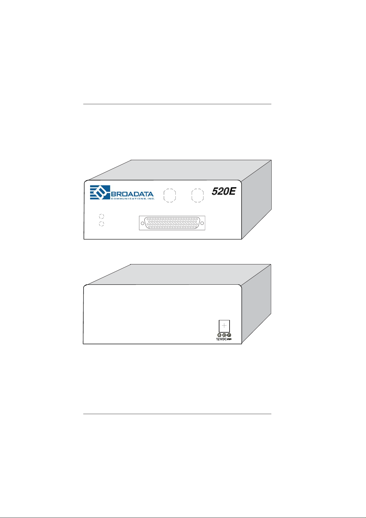
The 520E provides front panel LED indicators for power and optical link
status.
The 520E is available in a standalone or card cage format, thereby
accommodating multiple configurations, depending on the application.
Broadata Technical Support, CustomerService@Broadatacom.com
5
BCI 520E User’s Manual
Fiber Optic 8/16 Channel RS-422/RS-232 Data Transmission System
LINK
PWR
TX
RX
Figure 1-1
520E Front/Rear Panels
6
Broadata Technical Support, (800) 214-0222
Fiber Optic 8/16 Channel RS-422/RS-232 Data Transmission System
BCI 520E User’s Manual
2.0 SETUP
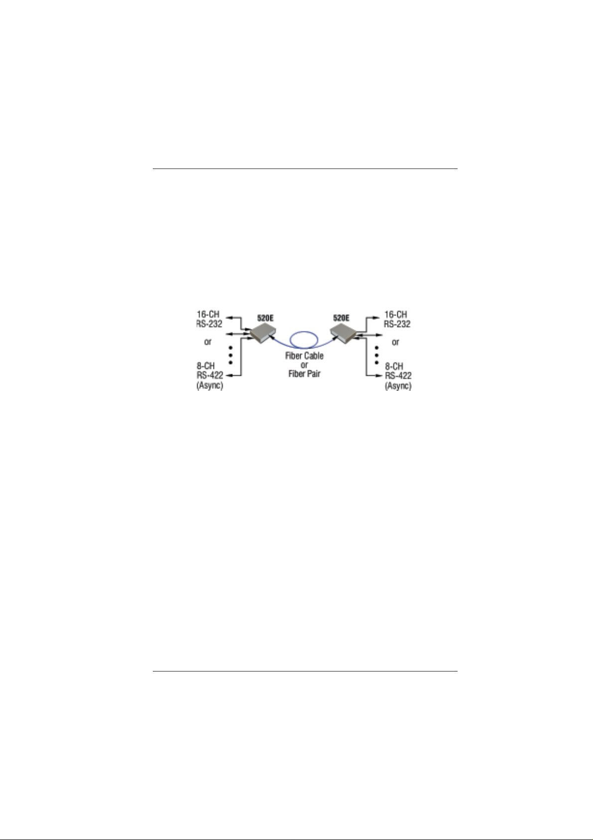
The BCI 520E Series units are used in pairs. One 520E transceiver unit
is located at the near end and connected through two optical fibers to
an identical 520E transceiver located at the far end of the link. Each
unit provides an electrical interface connector for the RS-232 or RS-422
data signals. Connections are one to one between both units. Figure 2-1
depicts a typical installation.
Figure 2-1
520E Setup
2.1 Mounting
Before installing the units into your housing, make sure there is
enough space to pull and connect both the electrical and optical
cables without stressing them beyond the manufacturer’s
limitations (also known as the bend radius minimum). Rack
mount kits are available for half-size versions only , with internal
power supplies.
2.2 Cabling and Connectors
In order to setup the BCI 520E properly , make sure to observe
the following instructions when installing the proper cables. The
520E requires two parts to the cabling setup: the electrical and
the optical.
Broadata Technical Support, CustomerService@Broadatacom.com
7

BCI 520E User’s Manual
Fiber Optic 8/16 Channel RS-422/RS-232 Data Transmission System
2.3 Electrical Cable Connection
The only available cable connections on the electrical side is
for the RS-232 or RS-422 connections.
2.3.1 Data Channel Connection
Use the following steps to connect to your data equipment.
1. Before connecting your user supplied equipment, wire
up the proper cabling to connect from the 520E to the
end-user’s equipment, observing T able 2-1 pinout s for
the various RS-232 or RS-422 applications. Note: The
520E units require a cable with a 78-pin interface in
order to convert the pinouts over to their respective
RS-232 or RS-422 equivalent. The pinouts for the 78-pin
connector is illustrated in Figure 2-2.
2. At the local end, connect one end of a serial computer
data cable to the user’s data device and the other end
to the 520E unit’s 78-pin connection. Repeat this step
for each RS-232 or RS-422 channel.
3. Repeat steps 1 and 2 for the far end observing the pinouts
for the 78-pin with their respective connector.
4. The following parts and tools are used for this 78-pin
connector.
a. D-Sub 78-pin, Mfg. P/N 180-078-172-000 or BCI
P/N 30304-0878.
b. Male Crimp pin, Mfg. P/N 180-001-170-001 or BCI
P/N 30060-0085.
c. Crimp tool from Paldin 1600 Series.
d. Metalized backshell for DB 78-pin, Mfg. P/N
979-050-020-121 or BCI P/N 30060-0979.
e. D-Sub 78-pin with solder cup pins, Mfg. P/N
180-078-102-01 1 or BCI P/N 30060-4878.
8
Broadata Technical Support, (800) 214-0222
 Loading...