

Broadata Communications 4800 User Manual
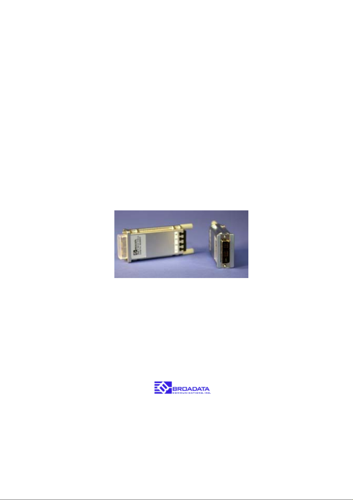
4800 Series
FIBER OPTIC
DVI EXTENSION SYSTEM
BCI reserves the right to make changes to the products described herein without
prior notice or consent. No liability is assumed as a result of their use or
application. All rights reserved.
©2006 Broadata Communications, Inc.
Fiber Optic DVI Extension System
BCI 4800 User’s Manual
SAFETY INSTRUCTIONS AND
COMPLIANCE DECLARATIONS
PLEASE OBSERVE THE FOLLOWING SAFETY
PRECAUTIONS AS OUR PRODUCTS CONT AIN
CLASS I LASER PRODUCTS
WARNING
Do not disconnect the fiber optic connector while the unit is powered
up. Exposure to laser radiation is possible when the laser fiber optic
connector is disconnected while the unit is powered up.
Although the fiber optic connectors in this product emit only Class 1
energy that is below the levels considered to be hazardous, one should
never stare directly into a fiber optic connector or an unconnected fiber
end unless one can be certain that no exposure to laser energy could
occur.
CAUTION
This manual is intended for use by trained service personnel. The use
of controls, making adjustments, or performing operations other than
those specified may result in hazardous radiation exposure.
The following label or equivalent is located on the surface of laser products.
This label indicates that the product is classified as a CLASS 1 LASER
PRODUCT.
CLASS 1 LASER PRODUCT
SURGE PROTECTION DEVICE RECOMMENDED
This product contains sensitive electrical components that may be
damaged by electrical spikes, surges, electric shock, lightning strikes,
etc. Use of surge protection systems is highly recommended in order
to protect and extend the life of your equipment.
Broadata Technical Support, CustomerService@Broadatacom.com
3

BCI 4800 User’s Manual
Fiber Optic DVI Extension System
TABLE OF CONTENTS
1.0 PRODUCT DESCRIPTION .............................................5
2.0 SETUP.............................................................................. 6
2.1 HARDWARE REQUIREMENTS ......................................6
2.2 SOFTWARE REQUIREMENTS ....................................... 9
2.3 AC/DC POWER ADAPTER TECHNICAL ADVISORY ....6
3.0 INSTALLATION ................................................................7
4.0 MAINTENANCE AND TROUBLESHOOTING ................ 9
4.1 MAINTENANCE ...............................................................9
4.2 TROUBLESHOOTING ....................................................9
5.0 SPECIFICATIONS..........................................................10
6.0 SERVICE PROCEDURE ............................................... 11
6.1 REPLACEMENT POLICY ............................................. 11
6.2 RETURN AND REPAIR SERVICE.................................11
7.0 LIMITED WARRANTY....................................................12
4
Broadata Technical Support, (800) 214-0222
Fiber Optic DVI Extension System
BCI 4800 User’s Manual
1.0 PRODUCT DESCRIPTION
The 4800 Series is a high performance, yet affordable, Fiber Optic DVI
Extension System that is designed to carry one (1) DVI channel, over
long distances through four (4) multimode fibers.
No user adjustments are required in the 4800 system due to the use of
advanced digital fiber optic transmission technology . This allows for a
quick and easy setup, offering trouble-free operation for many years to
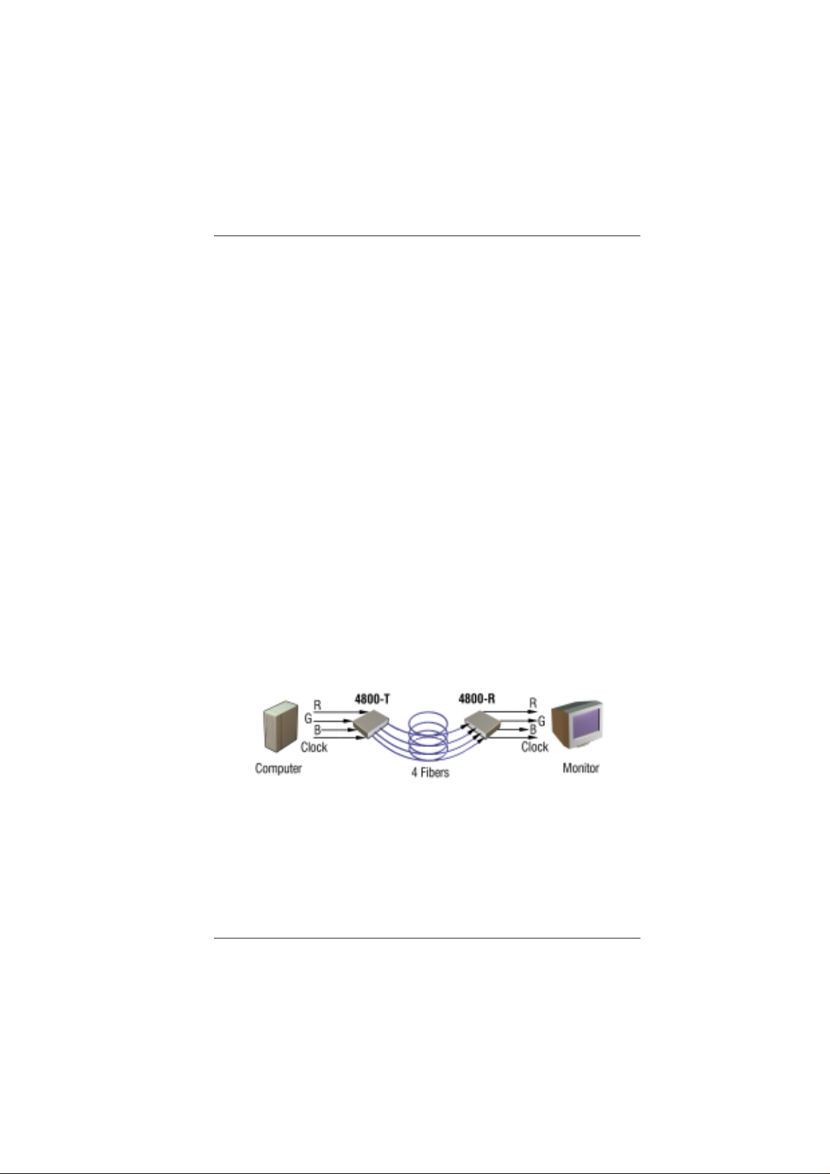
come. The 4800 system transmits R, G, B, clock signals separately
through one individual fiber and can support video resolution up to UXGA
(1600 x 1200).
The 4800 modules transmit 4 channels (R,G,B,Clk) of graphic data over
fiber. The DVI Digital Display Channel (DDC2B) interface is simulated
by programming EDID (Extended Display Identification Data) parameters
into a non-volatile memory device (EEPROM) located in the TX
(transmitter) module of the 4800 instead of directly from the display
peripheral. This saves the deployment of additional external lines. The
EEPROM is factory programmed to match the peripheral’s display mode.
Broadata defines it as “virtual DDC” or vDDC.
Figure 1-1
4800 Setup
Broadata Technical Support, CustomerService@Broadatacom.com
5

BCI 4800 User’s Manual
Fiber Optic DVI Extension System
2.0 SETUP
2.1 Hardware Requirements
1. Y ou have a graphic controller card or main board with a
DVI port in your PC, SUN, or Mac system. It should
support the maximum graphic resolution feature of the
display to be connected.
2. No special memory size, CPU speed and chipsets is
required.
3. Proper initial bring-up of the entire platform with its OS
and application using a short length cooper cable is
recommended prior to bring-up with the optical link.
2.2 Software Requirements
No special needs, if the DVI graphic controller and display
peripheral are operational with the platform’s OS and
application.
2.3 AC/DC Power Adapter Technical Advisory
The transmitter (TX) module of the 4800 is designed with a
power protection circuit to prevent power conflict between
the external DC power adapter and the power supply pin on
the DVI graphic card if both are present. The AC/DC power
adapter is included in case the graphic card does not have
a +5V pin.
Generally , the Receiver (RX) module will require the AC/DC
power adapter, as most DVI peripherals do not provide +5V .
Some projectors do have the hot pin; hence a good idea to
check availability to save having to deploy it.
BE SURE to attach the TX module upstream to the
computer video card and the RX module downstream to
the peripheral.
In general, most notebook PCs require using an AC/DC
power adaptor for the TX module.
6
Broadata Technical Support, (800) 214-0222

Fiber Optic DVI Extension System
BCI 4800 User’s Manual
3.0 INST ALLATION
Important: Please use the installation procedure below. Improper ,
or no operation may result if the start-up sequence is not correctly
followed.
1. Carefully unpack the contents of the shipping group.
2. With system power turned off, connect the upstream TX module
to the DVI receptacle of the computer.
3. Connect an AC/DC power adapter to the TX module of the 4800.
4. Connect the downstream RX module into the DVI receptacle of
the display.
5. Connect another AC/DC power adapter to the RX module of the
4800.
Note: Y ou might not have to use the AC/DC adapters if power
is supplied from the DVI pin from the graphic card or the
peripherals. After successfully completing the installation
instructions, unplug the adapters one at a time. If the system
doesn’t work properly, the AC/DC power adapter can be
reconnected while the system is on and the video should be
restored. Y ou can then remove one or both power adapters if
not required.
6. Remove the module dust covers and connect each duplex LC
fiber cable one by one as shown in Figure 2-1. Plug 1 to 1, 2 to
2, 3 to 3 and 4 to 4. Carefully recheck polarities and ensure the
duplex connectors are fully engaged.
Broadata Technical Support, CustomerService@Broadatacom.com
7
 Loading...