

Broadata Communications 300E User Manual
300E Series
MULTIPLE CHANNEL DIGITAL FIBER OPTIC
VIDEO/AUDIO/DATA
TRANSPORT SYSTEM
BCI reserves the right to make changes to the products described herein without
prior notice or consent. No liability is assumed as a result of their use or
application. All rights reserved.
©2006 Broadata Communications, Inc.
Multiple Channel Video/Audio/Data Transmission System
BCI 300E User’s Manual
SAFETY INSTRUCTIONS AND
COMPLIANCE DECLARATIONS
PLEASE OBSERVE THE FOLLOWING SAFETY
PRECAUTIONS AS OUR PRODUCTS CONT AIN
CLASS I LASER PRODUCTS
WARNING
Do not disconnect the fiber optic connector while the unit is powered
up. Exposure to laser radiation is possible when the laser fiber optic
connector is disconnected while the unit is powered up.
Although the fiber optic connectors in this product emit only Class 1
energy that is below the levels considered to be hazardous, one should
never stare directly into a fiber optic connector or an unconnected fiber
end unless one can be certain that no exposure to laser energy could
occur.
CAUTION
This manual is intended for use by trained service personnel. The use
of controls, making adjustments, or performing operations other than
those specified may result in hazardous radiation exposure.
The following label or equivalent is located on the surface of laser products.
This label indicates that the product is classified as a CLASS 1 LASER
PRODUCT.
CLASS 1 LASER PRODUCT
SURGE PROTECTION DEVICE RECOMMENDED
This product contains sensitive electrical components that may be
damaged by electrical spikes, surges, electric shock, lightning strikes,
etc. Use of surge protection systems is highly recommended in order
to protect and extend the life of your equipment.
Broadata Technical Support, CustomerService@Broadatacom.com
3

BCI 300E User’s Manual
Multiple Channel Video/Audio/Data Transmission System
TABLE OF CONTENTS
1.0 PRODUCT DESCRIPTION .............................................5
2.0 SETUP..............................................................................7
2.1 MOUNTING ...................................................................... 8
2.2 CABLING AND CONNECTORS ..................................... 8
2.2.1 ELECTRICAL CABLE CONNECTION .........................8
2.2.2 OPTICAL FIBER CONNECTION.................................8
2.2.1.1 AUDIO CONNECTION .............................................10
2.2.1.2 VIDEO CONNECTION............................................. 11
2.2.1.3 SERIAL DA TA INTERFACE......................................12
2.3 AC POWER CONNECTION .......................................... 15
3.0 OPERATION...................................................................16
4.0 MAINTENANCE AND TROUBLESHOOTING .............. 16
4.1 MAINTENANCE .............................................................16
4.2 TROUBLESHOOTING ..................................................17
5.0 SPECIFICATIONS..........................................................19
6.0 SERVICE PROCEDURE ............................................... 21
6.1 REPLACEMENT POLICY .............................................21
6.2 RETURN AND REPAIR SERVICE.................................21
7.0 LIMITED WARRANTY....................................................22
4
Broadata Technical Support, (800) 214-0222

Multiple Channel Video/Audio/Data Transmission System
BCI 300E User’s Manual
1.0 PRODUCT DESCRIPTION
The 310E/320E systems provide simultaneous transmission of multiple
channels of digitized stereo audio, video and/or data over one or one pair
of fiber. The standard 310E system transmits these video/audio/data
channels in one direction. The 320E system transmits and receives these
video/audio/data channels in both directions. The standard 310E/320E
system comes with 4- and 8-channel versions with each channel
containing one (1) NTSC/P AL/SECAM video, two (2) audios, and one (1)
serial data (RS-232/RS-422). Versions up to 16-channel video/audio/
data are also available for unidirectional links. In addition, the 310E/320E
has an option for S-video, and up to 8-channels of S-video can be
accommodated. The 310E/320E system is also capable of adding/
dropping video/audio/data channels in a ring or bus network configuration.
Please consult us for your custom design.
The 310E/320E features a digital fiber optic transmission technology,
capable of providing sharper video and crisp audio, little or no maintenance,
high functionality reliability , and low operating cost. The quality of video,
audio and data transmission in BCI's digital designs is much superior to
the analog transmission (based on amplitude or frequency modulation)
designs used by other manufacturers. No user adjustments are required
in the 310E/320E system, enabling quick setup and trouble-free operation.
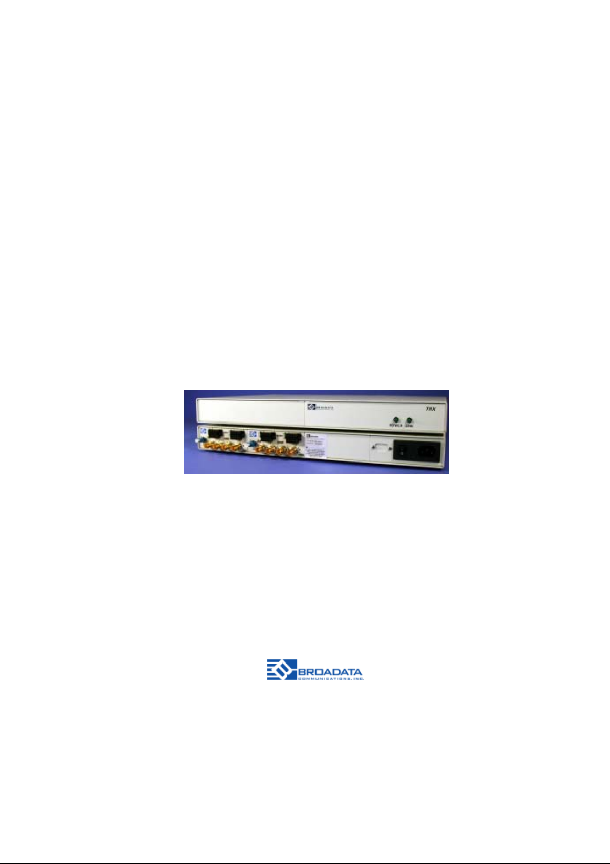
The 310E/320E comes in a rugged, standalone, and compact unit. Panel
connectors are provided for video (BNC), audio (terminal block), and data
(terminal block), and fiber connection (FC-type for singlemode fiber or
ST-type for multimode fiber). They are also easily monitored by separate
LED indicators for power, optical link, and channel activity .
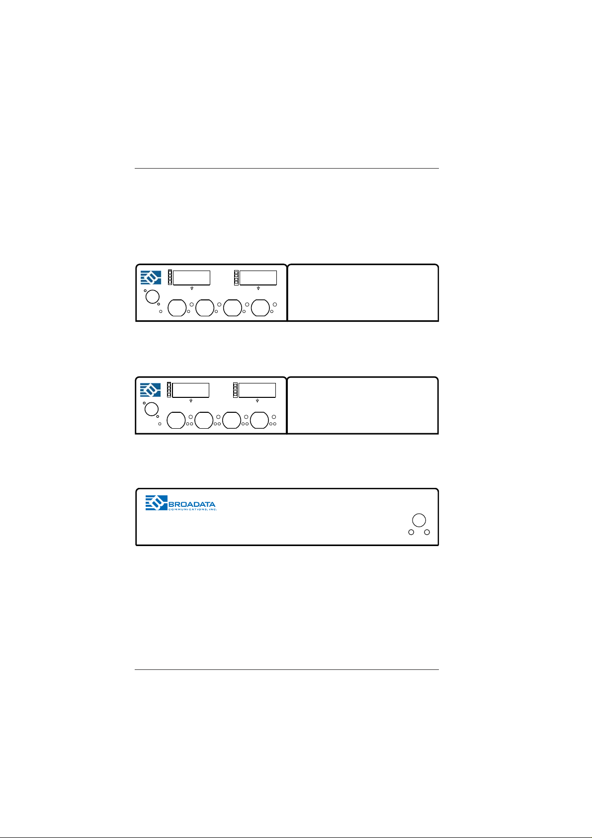
Due to its digital transmission design, the 310E/320E is capable of
addressing a variety of non-standard configurations. Figure 1-1 shows
the front and rear panels of the 300E Series.
Broadata Technical Support, CustomerService@Broadatacom.com
5
BCI 300E User’s Manual
Multiple Channel Video/Audio/Data Transmission System
3
1
2
3
4
1
RX
PWR
3
1
2
3
4
1
TX
PWR
_
_
_
_
+
+
1 2 34
_
_
_
_
+
+
1 2 34
4
2
300E
4
AUDIO
2
300E
AUDIO
7
5
6
7
8
5
+
7
5
6
7
8
5
+
8
_
_
_
_
6
+
VIDEO
8
_
_
_
_
6
+
VIDEO
12VDC
Figure 1-1
300E Front/Rear Panels
6
Broadata Technical Support, (800) 214-0222
Multiple Channel Video/Audio/Data Transmission System
BCI 300E User’s Manual
2.0 SETUP
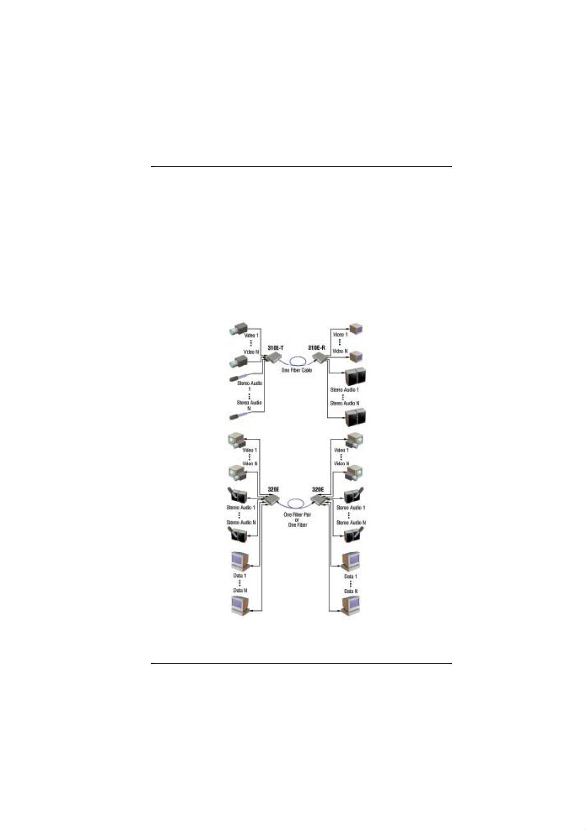
The BCI 300E Series units are used in pairs. In a unidirectional system,
one 310E transmitter is located at the near-end and connected to a
310E receiver located at the far-end, through a single fiber. In a
bi-directional system, one 300E transceiver unit is located at the near-end
and connected through two optical fibers to an identical 300E transceiver
located at the far-end of the link. Each unit provides a separate electrical
interface connector for the various audio, video and data signals.
Connections are one to one between the two units. Figure 2-1 depicts
two typical installations.
Figure 2-1
310E/320E Setup
Broadata Technical Support, CustomerService@Broadatacom.com
7

BCI 300E User’s Manual
Multiple Channel Video/Audio/Data Transmission System
2.1 Mounting
Before installing the units into your housing, make sure there is
enough space to pull and connect both the electrical and optical
cables without stressing them beyond the manufacturer’s
limitations (also known as the bend radius minimum). Rack
Mount kits are available through special order.
2.2 Cabling and Connectors
In order to setup the BCI 300E properly, make sure to observe
the following instructions when installing the proper cables. The
300E requires two parts to the cabling setup: the electrical and
the optical. For the optical part, observe the following
procedures, as there are various types of optical connectors as
illustrated on the following page.
2.2.1 Electrical Cable Connection
On the electrical side, it is required that the following steps be
observed when connecting the various audio, video and data
terminal devices, as they all require special attention, and are
the only available electrical connections. They are described
in the following steps.
2.2.2 Optical Fiber Connection
Most cable manufacturers identify individual fibers in the fiber
cable. Select an appropriate terminated fiber. Each unit’ s optical
ports in the system are specified for use with Multimode (62.5/
125 micron) fiber, or Singlemode (9/125 micron) fiber. Follow
the ensuing instructions for installing and connecting the fiber
optic links:
1. Ensure the power is off before proceeding with the fiber
optic cable installation.
8
Broadata Technical Support, (800) 214-0222
 Loading...