

Broadata Communications 1700 User Manual
1700 Series
FIBER OPTIC DIGIT A L
VIDEO/AUDIO TRANSPORT SYSTEM
BCI reserves the right to make changes to the products described herein without
prior notice or consent. No liability is assumed as a result of their use or
application. All rights reserved.
©2005 Broadata Communications, Inc.
Fiber Optic Digital Video/Audio Transport System
BCI 1700 User’s Manual
SAFETY INSTRUCTIONS AND
COMPLIANCE DECLARATIONS
PLEASE OBSERVE THE FOLLOWING SAFETY
PRECAUTIONS AS OUR PRODUCTS CONT AIN
CLASS I LASER PRODUCTS
WARNING
Do not disconnect the fiber optic connector while the unit is powered
up. Exposure to laser radiation is possible when the laser fiber optic
connector is disconnected while the unit is powered up.
Although the fiber optic connectors in this product emit only Class 1
energy that is below the levels considered to be hazardous, one should
never stare directly into a fiber optic connector or an unconnected fiber
end unless one can be certain that no exposure to laser energy could
occur.
CAUTION
This manual is intended for use by trained service personnel. The use
of controls, making adjustments, or performing operations other than
those specified may result in hazardous radiation exposure.
The following label or equivalent is located on the surface of laser products.
This label indicates that the product is classified as a CLASS 1 LASER
PRODUCT.
CLASS 1 LASER PRODUCT
SURGE PROTECTION DEVICE RECOMMENDED
This product contains sensitive electrical components that may be
damaged by electrical spikes, surges, electric shock, lightning strikes,
etc. Use of surge protection systems is highly recommended in order
to protect and extend the life of your equipment.
Broadata Technical Support, CustomerService@Broadatacom.com
3

BCI 1700 User’s Manual
Fiber Optic Digital Video/Audio Transport System
TABLE OF CONTENTS
1.0 PRODUCT DESCRIPTION .............................................5
2.0 SETUP.............................................................................. 7
2.1 MOUNTING ...................................................................... 8
2.2 CABLING AND CONNECTORS ..................................... 8
2.2.1 ELECTRICAL CABLE CONNECTION ........................8
2.2.2 DIGITAL VIDEO CONNECTION ..................................8
2.2.3 DIGITAL AUDIO CONNECTION ............................... 10
2.2.4 OPTICAL FIBER CONNECTION...............................11
2.4 POWER CONNECTION ................................................ 13
3.0 OPERATION................................................................... 14
4.0 MAINTENANCE AND TROUBLESHOOTING .............. 14
4.1 MAINTENANCE .............................................................14
4.2 TROUBLESHOOTING ..................................................15
5.0 SPECIFICATIONS..........................................................17
6.0 SERVICE PROCEDURE ............................................... 19
6.1 REPLACEMENT POLICY .............................................19
6.2 RETURN AND REPAIR SERVICE.................................19
7.0 LIMITED WARRANTY....................................................20
4
Broadata Technical Support, (800) 214-0222

Fiber Optic Digital Video/Audio Transport System
BCI 1700 User’s Manual
1.0 PRODUCT DESCRIPTION
The 1700 system provides simultaneous transmission of digital audio,
digital video and/or data over one or one pair of fibers. The 1700
unidirectional system transmits two (2) AES audios and one (1) SDI
video channel in one direction. The 1700 bi-directional system transmits
and receives two (2) AES audios and one (1) SDI video channel in both
directions. The video quality in the 1700 system meets SMPTE-259M
specifications and its audio specifications exceed AES3 standards. In
addition, the 2 AES audio channels can be optionally replaced by 2
stereo analog audio channels. Many versions of optical transmitter and
receiver combinations are available to address different distance
requirements.
The 1700 features a digital time-multiplexing fiber optic transmission
technology , capable of providing sharp video and crisp audio, with little
or no maintenance, high functionality reliability , and low operating cost.
In addition, the audio and video streams are totally independent. Thus
the break of one stream (video or audio) will not cause the break of the
other stream (audio or video). The quality of video, audio and data
transmission in BCI's digital designs is much superior to the embedded
video/audio transmission designs used by other manufacturers. No
user adjustments are required in the 1700 system, enabling quick setup
and trouble-free operation.
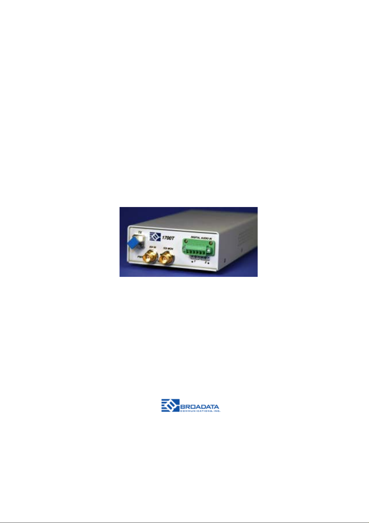
The 1700 comes with two packaging options: a rugged, standalone, and
compact unit, or a plug-in card for a card cage system. Panel connectors
are provided for video (BNC), audio (terminal block), and fiber connection
(FC-type for singlemode fiber or ST-type for multimode fiber). They are
also easily monitored by separate LED indicators for power, optical link,
and channel activity .
Broadata Technical Support, CustomerService@Broadatacom.com
5
BCI 1700 User’s Manual
+ --+--
-+---+
Fiber Optic Digital Video/Audio Transport System
PWR
TX
PWR
RX
LINK
SDI IN
1
SDI
SDI OUT
SDI
1700T
SDI MON
1700R
2
DIGITAL AUDIO IN
1 2
DIGITAL AUDIO OUT
1
-
2
12VDC
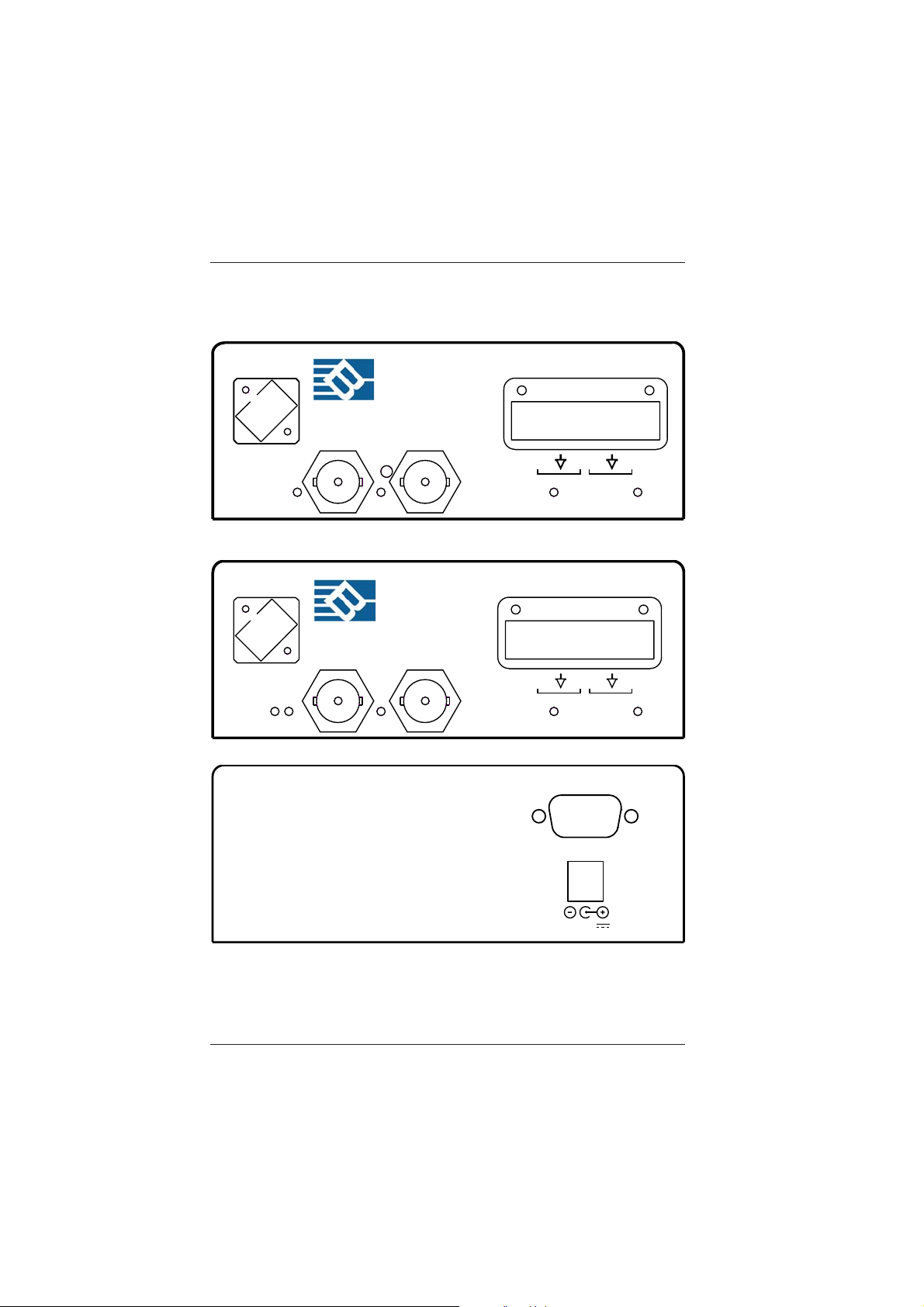
Figure 1-1
1700 Front/Rear Panels
6
Broadata Technical Support, (800) 214-0222
Fiber Optic Digital Video/Audio Transport System
BCI 1700 User’s Manual
2.0 SETUP
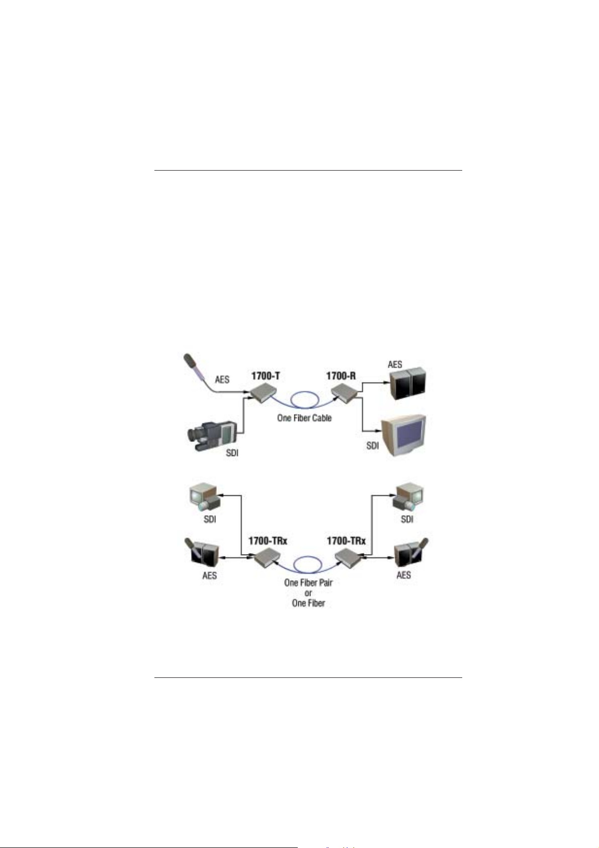
The BCI 1700 Series units are used in pairs. In a unidirectional
application, a 1700 transmitter (1700-T) is located at the near-end and
connected through one fiber to a 1700 receiver (1700-R) located at the
far-end. In a bi-directional application, one 1700 transceiver unit is located
at the near end and connected through two optical fibers to identical
1700 transceiver located at the far end of the link. Each unit provides a
separate electrical interface connector for the Serial Digital Video data
signals. Connections are one to one between both units. Figure 2-1
depicts a typical installation.
Figure 2-1
1700 Setup
Broadata Technical Support, CustomerService@Broadatacom.com
7

BCI 1700 User’s Manual
Fiber Optic Digital Video/Audio Transport System
2.1 Mounting
Before installing the units into your housing, make sure there is
enough space to pull and connect both the electrical and optical
cables without stressing them beyond the manufacturer’s
limitations (also known as the bend radius minimum). Rack
Mount kits are available through special order.
2.2 Cabling and Connectors
In order to set up the BCI 1700 properly , make sure to observe
the following instructions when installing the proper cables. The
1700 requires two parts to the cabling setup: the electrical and
the optical. For the optical part, observe the following
procedures, as there are various types of optical connectors as
illustrated on the following page.
2.2.1 Electrical Cable Connection
The only available cable connections on the electrical side are
for video sources.
Proceed with the following instructions when connecting the
various electrical devices.
2.2.2 Digital Video Connection
The 1700 unit provides 75 Ohm BNC connectors for digital video
input and output ports. Use the following procedure for
connections.
1. On the near end, connect the user’s digital video sources to
the 1700-T (transmitter) unit’s digital video input ports, using
a coaxial cable (i.e., Belden 8281 or better).
8
Broadata Technical Support, (800) 214-0222
 Loading...